Embed Size (px)
Citation preview
Valor® ODB++ Inside for Cadence Allegro
Software Version 9.3.1
February 2013
© 1996—2013 Mentor Graphics CorporationAll rights reserved.
This document contains information that is proprietary to Mentor Graphics Corporation. The original recipient of thisdocument may duplicate this document in whole or in part for internal business purposes only, provided that this entirenotice appears in all copies. In duplicating any part of this document, the recipient agrees to make every reasonableeffort to prevent the unauthorized use and distribution of the proprietary information.

This document is for information and instruction purposes. Mentor Graphics reserves the right to make changes in specifications and other information contained in this publication without prior notice, and the reader should, in all cases, consult Mentor Graphics to determine whether any changes have been made.
The terms and conditions governing the sale and licensing of Mentor Graphics products are set forth in written agreements between Mentor Graphics and its customers. No representation or other affirmation of fact contained in this publication shall be deemed to be a warranty or give rise to any liability of Mentor Graphics whatsoever.
MENTOR GRAPHICS MAKES NO WARRANTY OF ANY KIND WITH REGARD TO THIS MATERIAL INCLUDING, BUT NOT LIMITED TO, THE IMPLIED WARRANTIES OF MERCHANTABILITY AND FITNESS FOR A PARTICULAR PURPOSE.
MENTOR GRAPHICS SHALL NOT BE LIABLE FOR ANY INCIDENTAL, INDIRECT, SPECIAL, OR CONSEQUENTIAL DAMAGES WHATSOEVER (INCLUDING BUT NOT LIMITED TO LOST PROFITS) ARISING OUT OF OR RELATED TO THIS PUBLICATION OR THE INFORMATION CONTAINED IN IT, EVEN IF MENTOR GRAPHICS HAS BEEN ADVISED OF THE POSSIBILITY OF SUCH DAMAGES.
U.S. GOVERNMENT LICENSE RIGHTS: The software and documentation were developed entirely at private expense and are commercial computer software and commercial computer software documentation within the meaning of the applicable acquisition regulations. Accordingly, pursuant to FAR 48 CFR 12.212 and DFARS 48 CFR 227.7202, use, duplication and disclosure by or for the U.S. Government or a U.S. Government subcontractor is subject solely to the terms and conditions set forth in the license agreement provided with the software, except for provisions which are contrary to applicable mandatory federal laws.
TRADEMARKS: The trademarks, logos and service marks ("Marks") used herein are the property of Mentor Graphics Corporation or other parties. No one is permitted to use these Marks without the prior written consent of Mentor Graphics or the owner of the Mark, as applicable. The use herein of a third-party Mark is not an attempt to indicate Mentor Graphics as a source of a product, but is intended to indicate a product from, or associated with, a particular third party. A current list of Mentor Graphics’ trademarks may be viewed at: www.mentor.com/trademarks.
Mentor Graphics Corporation8005 S.W. Boeckman Road, Wilsonville, Oregon 97070-7777
Telephone: 503.685.7000Toll-Free Telephone: 800.592.2210
Website: www.mentor.comSupportNet: supportnet.mentor.com/
Send Feedback on Documentation: supportnet.mentor.com/doc_feedback_form
ODB++ Inside for Cadence Allegro, V9.3.1 3February 2013
Table of Contents
Chapter 1ODB++ Inside for Cadence Allegro . . . . . . . . . . . . . . . . . . . . . . . . . . . . . . . . . . . . . . . . . . . 5
Translation Workflow . . . . . . . . . . . . . . . . . . . . . . . . . . . . . . . . . . . . . . . . . . . . . . . . . . . . . . 5System Requirements . . . . . . . . . . . . . . . . . . . . . . . . . . . . . . . . . . . . . . . . . . . . . . . . . . . . . . 6
Chapter 2Exporting to ODB++. . . . . . . . . . . . . . . . . . . . . . . . . . . . . . . . . . . . . . . . . . . . . . . . . . . . . . . . 7
Using the Translator. . . . . . . . . . . . . . . . . . . . . . . . . . . . . . . . . . . . . . . . . . . . . . . . . . . . . . . . 7Specifying File Options and Output Options. . . . . . . . . . . . . . . . . . . . . . . . . . . . . . . . . . . . . 8Specifying Parameters Specific to Cadence Allegro . . . . . . . . . . . . . . . . . . . . . . . . . . . . . . . 10Saving the Configuration . . . . . . . . . . . . . . . . . . . . . . . . . . . . . . . . . . . . . . . . . . . . . . . . . . . . 17Editing the Matrix File. . . . . . . . . . . . . . . . . . . . . . . . . . . . . . . . . . . . . . . . . . . . . . . . . . . . . . 18
Chapter 3Viewing the Product Model in ODB++ Viewer . . . . . . . . . . . . . . . . . . . . . . . . . . . . . . . . . . 21
Opening ODB++ Viewer . . . . . . . . . . . . . . . . . . . . . . . . . . . . . . . . . . . . . . . . . . . . . . . . . . . . 21File Menu Options . . . . . . . . . . . . . . . . . . . . . . . . . . . . . . . . . . . . . . . . . . . . . . . . . . . . . . . 23Actions Menu Options . . . . . . . . . . . . . . . . . . . . . . . . . . . . . . . . . . . . . . . . . . . . . . . . . . . . 24View Menu Options . . . . . . . . . . . . . . . . . . . . . . . . . . . . . . . . . . . . . . . . . . . . . . . . . . . . . . 24Help Menu Options. . . . . . . . . . . . . . . . . . . . . . . . . . . . . . . . . . . . . . . . . . . . . . . . . . . . . . . 25Board Viewer Right-Click Menu Options . . . . . . . . . . . . . . . . . . . . . . . . . . . . . . . . . . . . . 25Board Viewer Shortcuts . . . . . . . . . . . . . . . . . . . . . . . . . . . . . . . . . . . . . . . . . . . . . . . . . . . 26
Viewing Component or Feature Properties . . . . . . . . . . . . . . . . . . . . . . . . . . . . . . . . . . . . . . 27Setting Display Colors . . . . . . . . . . . . . . . . . . . . . . . . . . . . . . . . . . . . . . . . . . . . . . . . . . . . . . 30
Chapter 4System Administrator Notes . . . . . . . . . . . . . . . . . . . . . . . . . . . . . . . . . . . . . . . . . . . . . . . . . 33
Running the Translator from Design Workbench . . . . . . . . . . . . . . . . . . . . . . . . . . . . . . . . . 33Setting Configuration Parameters . . . . . . . . . . . . . . . . . . . . . . . . . . . . . . . . . . . . . . . . . . . . . 34
Using the config file to set Configuration Parameters . . . . . . . . . . . . . . . . . . . . . . . . . . . . 34Configuration Parameters . . . . . . . . . . . . . . . . . . . . . . . . . . . . . . . . . . . . . . . . . . . . . . . . . . 34
Setting Environment Variables . . . . . . . . . . . . . . . . . . . . . . . . . . . . . . . . . . . . . . . . . . . . . . . 39Configuring a Thermal Model . . . . . . . . . . . . . . . . . . . . . . . . . . . . . . . . . . . . . . . . . . . . . . . . 39
Structure of a Thermal Model File . . . . . . . . . . . . . . . . . . . . . . . . . . . . . . . . . . . . . . . . . . . 40BNF (Backus-Naur Form) of Rules . . . . . . . . . . . . . . . . . . . . . . . . . . . . . . . . . . . . . . . . . . 40Sample Thermal Model File . . . . . . . . . . . . . . . . . . . . . . . . . . . . . . . . . . . . . . . . . . . . . . . . 42
Generating the Extraction Files . . . . . . . . . . . . . . . . . . . . . . . . . . . . . . . . . . . . . . . . . . . . . . . 42comps_<product_model>.out . . . . . . . . . . . . . . . . . . . . . . . . . . . . . . . . . . . . . . . . . . . . . . . 43films_<product_model>.out . . . . . . . . . . . . . . . . . . . . . . . . . . . . . . . . . . . . . . . . . . . . . . . . 43geoms_<product_model>.out . . . . . . . . . . . . . . . . . . . . . . . . . . . . . . . . . . . . . . . . . . . . . . . 44layers_<product_model>.out . . . . . . . . . . . . . . . . . . . . . . . . . . . . . . . . . . . . . . . . . . . . . . . 44nets_<product_model>.out . . . . . . . . . . . . . . . . . . . . . . . . . . . . . . . . . . . . . . . . . . . . . . . . . 44
Table of Contents
4February 2013
ODB++ Inside for Cadence Allegro, V9.3.1
pads_<product_model>.out . . . . . . . . . . . . . . . . . . . . . . . . . . . . . . . . . . . . . . . . . . . . . . . . 45pins_<product_model>.out . . . . . . . . . . . . . . . . . . . . . . . . . . . . . . . . . . . . . . . . . . . . . . . . . 45props_<product_model>.out. . . . . . . . . . . . . . . . . . . . . . . . . . . . . . . . . . . . . . . . . . . . . . . . 45tech_<product_model>.out . . . . . . . . . . . . . . . . . . . . . . . . . . . . . . . . . . . . . . . . . . . . . . . . . 45
Using Command Line Parameters . . . . . . . . . . . . . . . . . . . . . . . . . . . . . . . . . . . . . . . . . . . . . 46Supported Features . . . . . . . . . . . . . . . . . . . . . . . . . . . . . . . . . . . . . . . . . . . . . . . . . . . . . . . . 49
Skipping Extraction of Net Impedance Average . . . . . . . . . . . . . . . . . . . . . . . . . . . . . . . . 49Placing Components Underneath Raised Components . . . . . . . . . . . . . . . . . . . . . . . . . . . 50Using Height Parameters for Keepout Areas . . . . . . . . . . . . . . . . . . . . . . . . . . . . . . . . . . . 51Back-Drill Information is Translated . . . . . . . . . . . . . . . . . . . . . . . . . . . . . . . . . . . . . . . . . 52Support for Mirrored Padstacks . . . . . . . . . . . . . . . . . . . . . . . . . . . . . . . . . . . . . . . . . . . . . 52Support for the COMPONENT KEEPOUT Class . . . . . . . . . . . . . . . . . . . . . . . . . . . . . . . 52
Release Notes. . . . . . . . . . . . . . . . . . . . . . . . . . . . . . . . . . . . . . . . . . . . . . . . . . . . . . . . . . . . . 53Version 9.0 Features and Resolved Issues . . . . . . . . . . . . . . . . . . . . . . . . . . . . . . . . . . . . . 53Version 9.1 Features and Resolved Issues . . . . . . . . . . . . . . . . . . . . . . . . . . . . . . . . . . . . . 54Version 9.2 Features and Resolved Issues . . . . . . . . . . . . . . . . . . . . . . . . . . . . . . . . . . . . . 55Version 9.3 Features and Resolved Issues . . . . . . . . . . . . . . . . . . . . . . . . . . . . . . . . . . . . . 55
End-User License Agreement
ODB++ Inside for Cadence Allegro, V9.3.1 5February 2013
Chapter 1ODB++ Inside for Cadence Allegro
ODB++ is a format designed to capture all CAD or EDA assembly and PCB fabrication information in a single, unified database.
ODB++ Inside for Cadence Allegro contains the BRD2ODB translator and the ODB++ Viewer.
• The translator converts Cadence Allegro board files to ODB++ V7.
• The translator supports Cadence Allegro version 11 - 16.5, and OrCAD Designer V16 and up.
• ODB++ Viewer displays the resulting ODB++ information, graphically. See “Viewing the Product Model in ODB++ Viewer” on page 21.
When Allegro is to be launched from the Allegro Design Workbench, environment variable PCBDW_USER_PATH must be set when ODB++ Inside is installed, as described in “Running the Translator from Design Workbench” on page 33.
The Cadence Allegro V1.6 APD family of products includes Cadence SiP. The translator can read sip files in addition to brd files and mcm files.
This version of the translator does not include the option to save as the earlier ODB++ V6. This functionality was removed so that there is no confusion over what should be sent to manufacturing. Manufacturers must use a software version capable of reading ODB++ V7 format. Mentor/Frontline applications such as Genesis work with a variation of the ODB++ format, but they can import and use the ODB++ V7 format.
Translation Workflow . . . . . . . . . . . . . . . . . . . . . . . . . . . . . . . . . . . . . . . . . . . . . . . . . . . . . 5
System Requirements . . . . . . . . . . . . . . . . . . . . . . . . . . . . . . . . . . . . . . . . . . . . . . . . . . . . . 6
Translation WorkflowTo translate a Mentor Graphics Board Station design to ODB++, perform the following tasks:
Task Information
Check that the system meets the requirements
“System Requirements” on page 6
Set up the Environment “System Administrator Notes” on page 33
Export the design to ODB++ “Exporting to ODB++” on page 7
ODB++ Inside for Cadence Allegro, V9.3.16
ODB++ Inside for Cadence AllegroSystem Requirements
February 2013
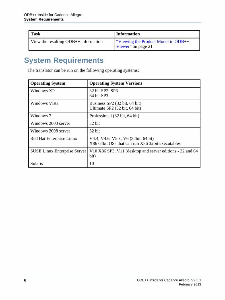
System RequirementsThe translator can be run on the following operating systems:
View the resulting ODB++ information “Viewing the Product Model in ODB++ Viewer” on page 21
Operating System Operating System Versions
Windows XP 32 bit SP2, SP364 bit SP3
Windows Vista Business SP2 (32 bit, 64 bit)Ultimate SP2 (32 bit, 64 bit)
Windows 7 Professional (32 bit, 64 bit)
Windows 2003 server 32 bit
Windows 2008 server 32 bit
Red Hat Enterprise Linux V4.4, V4.6, V5.x, V6 (32bit, 64bit)X86 64bit OSs that can run X86 32bit executables
SUSE Linux Enterprise Server V10 X86 SP3, V11 (desktop and server editions - 32 and 64 bit)
Solaris 10
Task Information
ODB++ Inside for Cadence Allegro, V9.3.1 7February 2013
Chapter 2Exporting to ODB++
Using the Translator . . . . . . . . . . . . . . . . . . . . . . . . . . . . . . . . . . . . . . . . . . . . . . . . . . . . . . 7
Specifying File Options and Output Options . . . . . . . . . . . . . . . . . . . . . . . . . . . . . . . . . . 8
Specifying Parameters Specific to Cadence Allegro . . . . . . . . . . . . . . . . . . . . . . . . . . . . . 10
Saving the Configuration . . . . . . . . . . . . . . . . . . . . . . . . . . . . . . . . . . . . . . . . . . . . . . . . . . 17
Editing the Matrix File . . . . . . . . . . . . . . . . . . . . . . . . . . . . . . . . . . . . . . . . . . . . . . . . . . . . 18
Using the TranslatorYou use the ODB++ Inside for Cadence Allegro translator to specify parameters and to run the translation to export a Cadence Allegro design to ODB++.
Procedure
1. Perform the following tasks as necessary:
o “Setting Configuration Parameters” on page 34.
o “Setting Environment Variables” on page 39.
o “Configuring a Thermal Model” on page 39.
o “Generating the Extraction Files” on page 42.
2. Open ODB++ Inside in one of these ways. See “Using Command Line Parameters” on page 46.
o From within Cadence Allegro, using the menu option.
o In Windows, the translator can be activated from a line mode command:
Command line: “%ALLEGRO_BRD2ODB%/brd2odb.exe” -gui
o In UNIX, type the following command: $ALLEGRO_BRD2ODB/brd2odb -gui
3. Specify the information described in “Specifying File Options and Output Options” on page 8.
4. If necessary, perform the following tasks:
o “Specifying Parameters Specific to Cadence Allegro” on page 10
o “Editing the Matrix File” on page 18
ODB++ Inside for Cadence Allegro, V9.3.18
Exporting to ODB++Specifying File Options and Output Options
February 2013
5. If you will be using these parameters for subsequent translations, see “Saving the Configuration” on page 17.
6. Click Run to perform the translation.
Specifying File Options and Output OptionsYou must provide input and output paths and output options needed by the translator.
If you will be using these parameters for subsequent translations, see “Saving the Configuration” on page 17.
Procedure
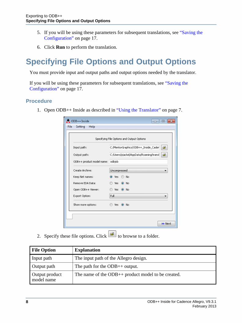
1. Open ODB++ Inside as described in “Using the Translator” on page 7.
2. Specify these file options. Click to browse to a folder.
File Option Explanation
Input path The input path of the Allegro design.
Output path The path for the ODB++ output.
Output product model name
The name of the ODB++ product model to be created.
Exporting to ODB++Specifying File Options and Output Options
ODB++ Inside for Cadence Allegro, V9.3.1 9February 2013
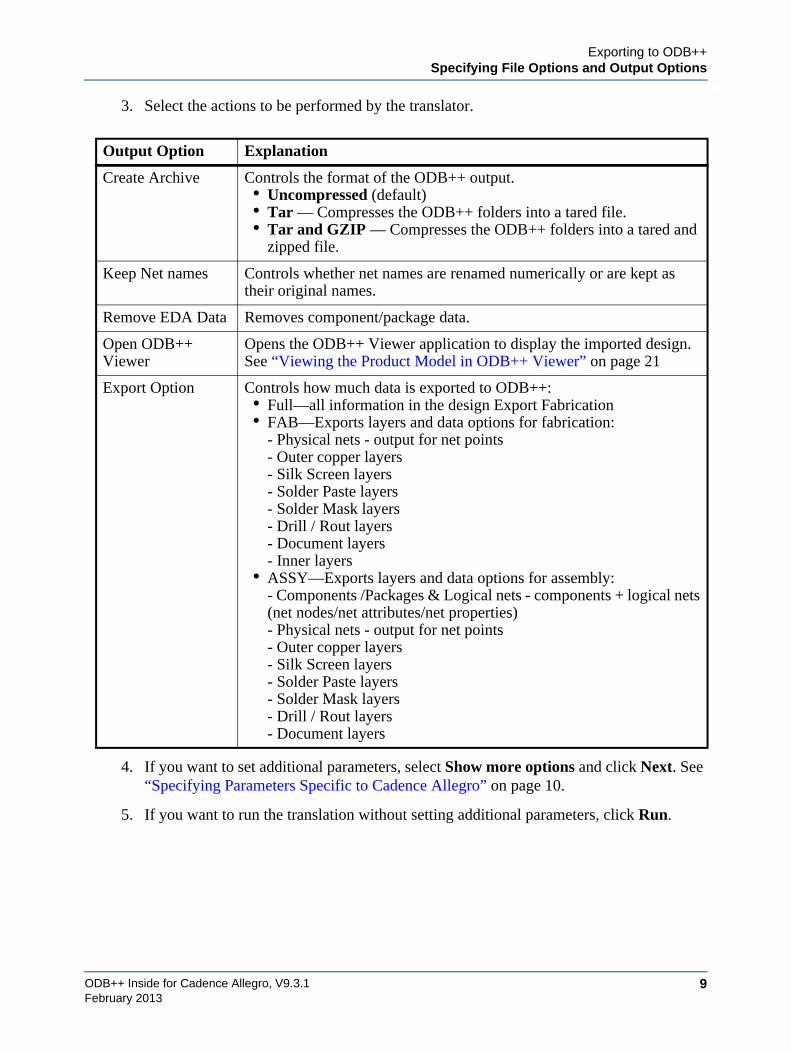
3. Select the actions to be performed by the translator.
4. If you want to set additional parameters, select Show more options and click Next. See “Specifying Parameters Specific to Cadence Allegro” on page 10.
5. If you want to run the translation without setting additional parameters, click Run.
Output Option Explanation
Create Archive Controls the format of the ODB++ output.• Uncompressed (default)• Tar — Compresses the ODB++ folders into a tared file. • Tar and GZIP — Compresses the ODB++ folders into a tared and
zipped file.
Keep Net names Controls whether net names are renamed numerically or are kept as their original names.
Remove EDA Data Removes component/package data.
Open ODB++ Viewer
Opens the ODB++ Viewer application to display the imported design. See “Viewing the Product Model in ODB++ Viewer” on page 21
Export Option Controls how much data is exported to ODB++:• Full—all information in the design Export Fabrication• FAB—Exports layers and data options for fabrication:
- Physical nets - output for net points- Outer copper layers- Silk Screen layers- Solder Paste layers- Solder Mask layers- Drill / Rout layers- Document layers- Inner layers
• ASSY—Exports layers and data options for assembly:- Components /Packages & Logical nets - components + logical nets (net nodes/net attributes/net properties)- Physical nets - output for net points- Outer copper layers- Silk Screen layers- Solder Paste layers- Solder Mask layers- Drill / Rout layers- Document layers
ODB++ Inside for Cadence Allegro, V9.3.110
Exporting to ODB++Specifying Parameters Specific to Cadence Allegro
February 2013
Specifying Parameters Specific to Cadence Allegro
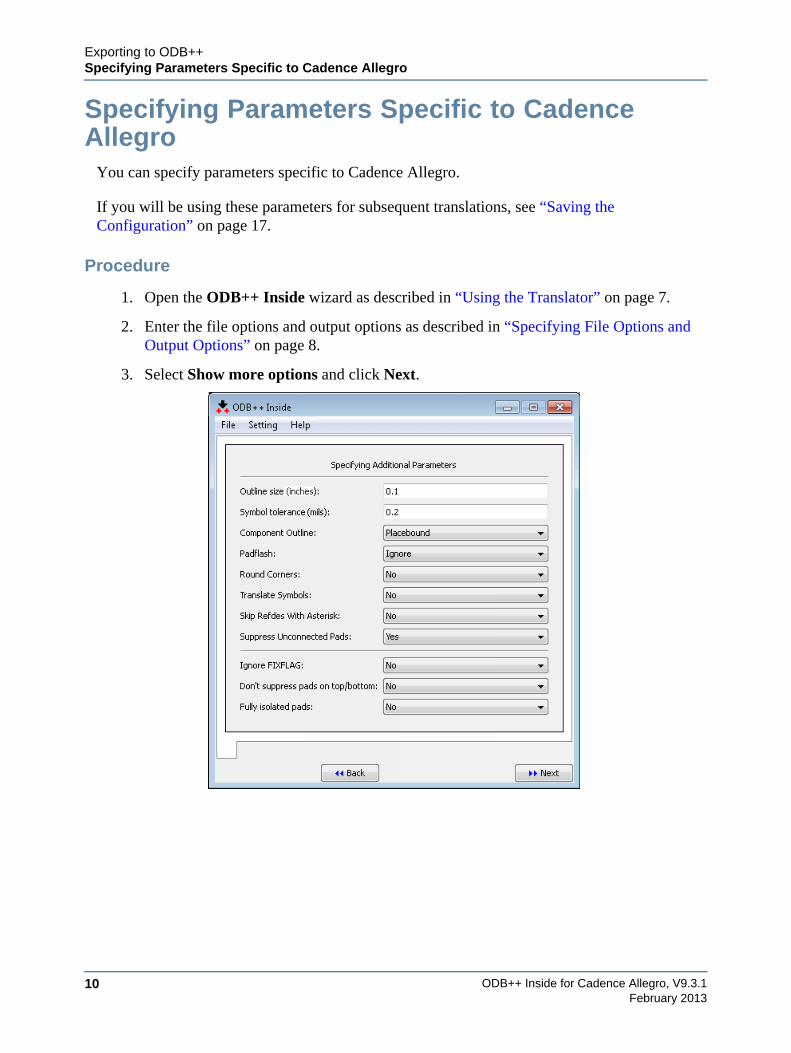
You can specify parameters specific to Cadence Allegro.
If you will be using these parameters for subsequent translations, see “Saving the Configuration” on page 17.
Procedure
1. Open the ODB++ Inside wizard as described in “Using the Translator” on page 7.
2. Enter the file options and output options as described in “Specifying File Options and Output Options” on page 8.
3. Select Show more options and click Next.
Exporting to ODB++Specifying Parameters Specific to Cadence Allegro
ODB++ Inside for Cadence Allegro, V9.3.1 11February 2013
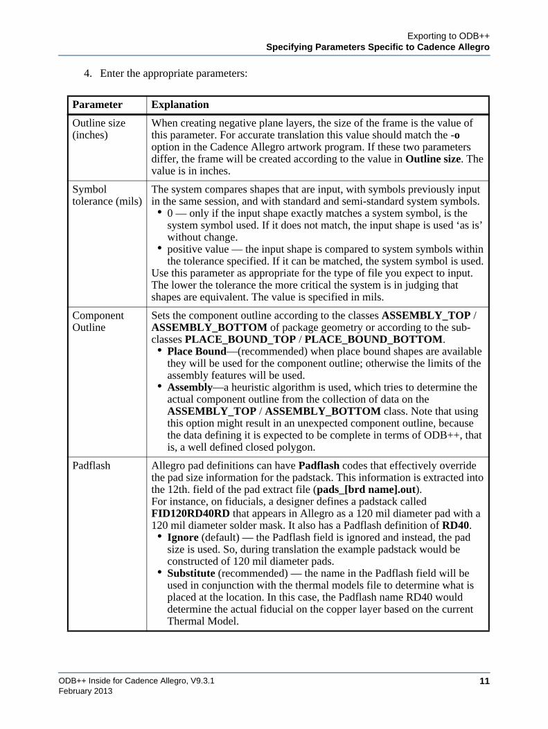
4. Enter the appropriate parameters:
Parameter Explanation
Outline size (inches)
When creating negative plane layers, the size of the frame is the value of this parameter. For accurate translation this value should match the -o option in the Cadence Allegro artwork program. If these two parameters differ, the frame will be created according to the value in Outline size. The value is in inches.
Symbol tolerance (mils)
The system compares shapes that are input, with symbols previously input in the same session, and with standard and semi-standard system symbols. • 0 — only if the input shape exactly matches a system symbol, is the
system symbol used. If it does not match, the input shape is used ‘as is’ without change.
• positive value — the input shape is compared to system symbols within the tolerance specified. If it can be matched, the system symbol is used.
Use this parameter as appropriate for the type of file you expect to input. The lower the tolerance the more critical the system is in judging that shapes are equivalent. The value is specified in mils.
Component Outline
Sets the component outline according to the classes ASSEMBLY_TOP / ASSEMBLY_BOTTOM of package geometry or according to the sub-classes PLACE_BOUND_TOP / PLACE_BOUND_BOTTOM.• Place Bound—(recommended) when place bound shapes are available
they will be used for the component outline; otherwise the limits of the assembly features will be used.
• Assembly—a heuristic algorithm is used, which tries to determine the actual component outline from the collection of data on the ASSEMBLY_TOP / ASSEMBLY_BOTTOM class. Note that using this option might result in an unexpected component outline, because the data defining it is expected to be complete in terms of ODB++, that is, a well defined closed polygon.
Padflash Allegro pad definitions can have Padflash codes that effectively override the pad size information for the padstack. This information is extracted into the 12th. field of the pad extract file (pads_[brd name].out).For instance, on fiducials, a designer defines a padstack called FID120RD40RD that appears in Allegro as a 120 mil diameter pad with a 120 mil diameter solder mask. It also has a Padflash definition of RD40.• Ignore (default) — the Padflash field is ignored and instead, the pad
size is used. So, during translation the example padstack would be constructed of 120 mil diameter pads.
• Substitute (recommended) — the name in the Padflash field will be used in conjunction with the thermal models file to determine what is placed at the location. In this case, the Padflash name RD40 would determine the actual fiducial on the copper layer based on the current Thermal Model.
ODB++ Inside for Cadence Allegro, V9.3.112
Exporting to ODB++Specifying Parameters Specific to Cadence Allegro
February 2013
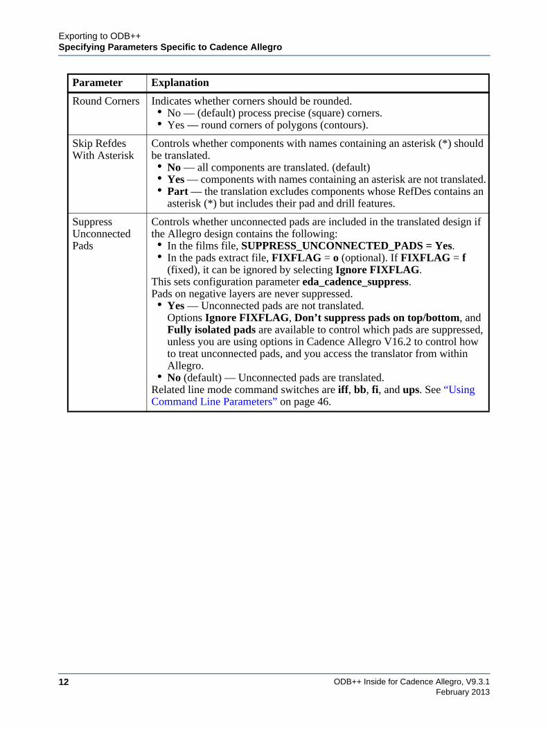
Round Corners Indicates whether corners should be rounded.• No — (default) process precise (square) corners.• Yes — round corners of polygons (contours).
Skip Refdes With Asterisk
Controls whether components with names containing an asterisk (*) should be translated.• No — all components are translated. (default)• Yes — components with names containing an asterisk are not translated.• Part — the translation excludes components whose RefDes contains an
asterisk (*) but includes their pad and drill features.
Suppress Unconnected Pads
Controls whether unconnected pads are included in the translated design if the Allegro design contains the following:• In the films file, SUPPRESS_UNCONNECTED_PADS = Yes.• In the pads extract file, FIXFLAG = o (optional). If FIXFLAG = f
(fixed), it can be ignored by selecting Ignore FIXFLAG.This sets configuration parameter eda_cadence_suppress.Pads on negative layers are never suppressed.• Yes — Unconnected pads are not translated.
Options Ignore FIXFLAG, Don’t suppress pads on top/bottom, and Fully isolated pads are available to control which pads are suppressed, unless you are using options in Cadence Allegro V16.2 to control how to treat unconnected pads, and you access the translator from within Allegro.
• No (default) — Unconnected pads are translated.Related line mode command switches are iff, bb, fi, and ups. See “Using Command Line Parameters” on page 46.
Parameter Explanation
Exporting to ODB++Specifying Parameters Specific to Cadence Allegro
ODB++ Inside for Cadence Allegro, V9.3.1 13February 2013
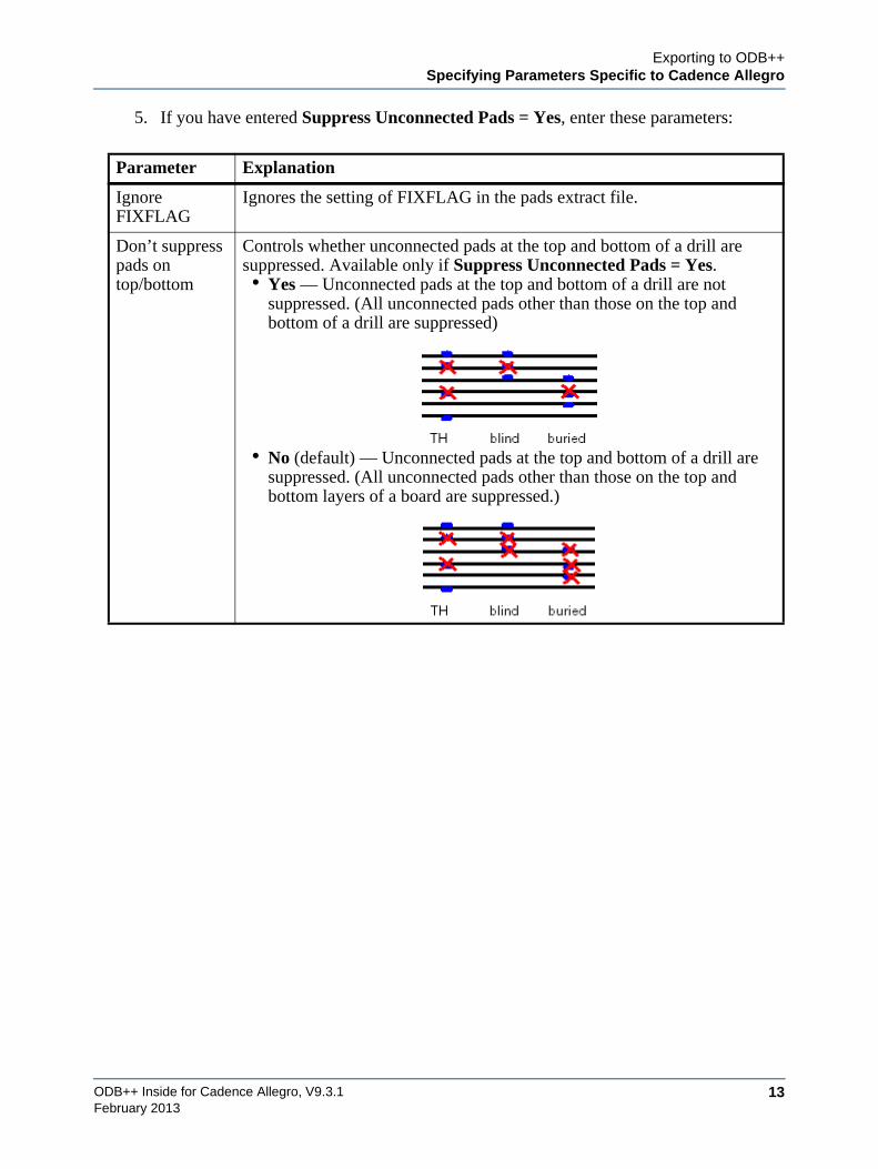
5. If you have entered Suppress Unconnected Pads = Yes, enter these parameters:
Parameter Explanation
Ignore FIXFLAG
Ignores the setting of FIXFLAG in the pads extract file.
Don’t suppress pads on top/bottom
Controls whether unconnected pads at the top and bottom of a drill are suppressed. Available only if Suppress Unconnected Pads = Yes.• Yes — Unconnected pads at the top and bottom of a drill are not
suppressed. (All unconnected pads other than those on the top and bottom of a drill are suppressed)
• No (default) — Unconnected pads at the top and bottom of a drill are suppressed. (All unconnected pads other than those on the top and bottom layers of a board are suppressed.)
ODB++ Inside for Cadence Allegro, V9.3.114
Exporting to ODB++Specifying Parameters Specific to Cadence Allegro
February 2013
6. Click Next.
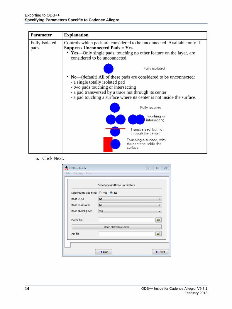
Fully isolated pads
Controls which pads are considered to be unconnected. Available only if Suppress Unconnected Pads = Yes.• Yes—Only single pads, touching no other feature on the layer, are
considered to be unconnected.
• No—(default) All of these pads are considered to be unconnected:- a single totally isolated pad- two pads touching or intersecting- a pad transversed by a trace not through its center- a pad touching a surface where its center is not inside the surface.
Parameter Explanation
Exporting to ODB++Specifying Parameters Specific to Cadence Allegro
ODB++ Inside for Cadence Allegro, V9.3.1 15February 2013
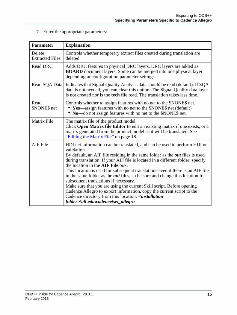
7. Enter the appropriate parameters:
Parameter Explanation
Delete Extracted Files
Controls whether temporary extract files created during translation are deleted.
Read DRC Adds DRC features to physical DRC layers. DRC layers are added as BOARD document layers. Some can be merged into one physical layer depending on configuration parameter settings.
Read SQA Data Indicates that Signal Quality Analysis data should be read (default). If SQA data is not needed, you can clear this option. The Signal Quality data layer is not created nor is the tech file read. The translation takes less time.
Read $NONE$ net
Controls whether to assign features with no net to the $NONE$ net.• Yes—assign features with no net to the $NONE$ net (default)• No—do not assign features with no net to the $NONE$ net.
Matrix File The matrix file of the product model.Click Open Matrix file Editor to edit an existing matrix if one exists, or a matrix generated from the product model as it will be translated. See “Editing the Matrix File” on page 18.
AIF File HDI net information can be translated, and can be used to perform HDI net validation.By default, an AIF file residing in the same folder as the out files is used during translation. If your AIF file is located in a different folder, specify the location in the AIF File box.This location is used for subsequent translations even if there is an AIF file in the same folder as the out files, so be sure and change this location for subsequent translations if necessary.Make sure that you are using the current Skill script. Before opening Cadence Allegro to export information, copy the current script to the Cadence directory from this location: <installation folder>\all\eda\cadence\set_allegro
ODB++ Inside for Cadence Allegro, V9.3.116
Exporting to ODB++Specifying Parameters Specific to Cadence Allegro
February 2013
8. Click Next.
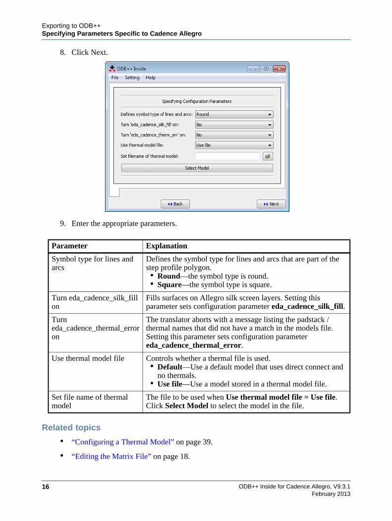
9. Enter the appropriate parameters.
Related topics
• “Configuring a Thermal Model” on page 39.
• “Editing the Matrix File” on page 18.
Parameter Explanation
Symbol type for lines and arcs
Defines the symbol type for lines and arcs that are part of the step profile polygon.• Round—the symbol type is round.• Square—the symbol type is square.
Turn eda_cadence_silk_fill on
Fills surfaces on Allegro silk screen layers. Setting this parameter sets configuration parameter eda_cadence_silk_fill.
Turn eda_cadence_thermal_error on
The translator aborts with a message listing the padstack / thermal names that did not have a match in the models file. Setting this parameter sets configuration parameter eda_cadence_thermal_error.
Use thermal model file Controls whether a thermal file is used.• Default—Use a default model that uses direct connect and
no thermals.• Use file—Use a model stored in a thermal model file.
Set file name of thermal model
The file to be used when Use thermal model file = Use file.Click Select Model to select the model in the file.
Exporting to ODB++Saving the Configuration
ODB++ Inside for Cadence Allegro, V9.3.1 17February 2013
Saving the ConfigurationIf you will be using the same parameters for several translations, you can save the configuration to a file.
You can save the configuration to the standard system location, to the standard user location, or to another location. The user-level configuration, if it exists, is loaded when ODB++ Inside starts. Otherwise, the system-level configuration is used.
Procedure
1. Run the ODB++ Inside wizard as described in “Using the Translator” on page 7.
2. Enter parameters as described in “Specifying File Options and Output Options” on page 8.
3. Enter parameters as described in “Specifying Parameters Specific to Cadence Allegro” on page 10.
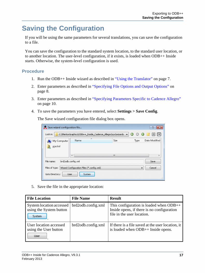
4. To save the parameters you have entered, select Settings > Save Config.
The Save wizard configuration file dialog box opens.
5. Save the file in the appropriate location:
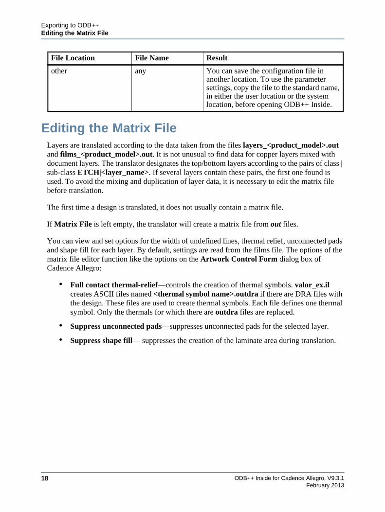
File Location File Name Result
System location accessed using the System button
.
brd2odb.config.xml This configuration is loaded when ODB++ Inside opens, if there is no configuration file in the user location.
User location accessed using the User button
.
brd2odb.config.xml If there is a file saved at the user location, it is loaded when ODB++ Inside opens.
ODB++ Inside for Cadence Allegro, V9.3.118
Exporting to ODB++Editing the Matrix File
February 2013
Editing the Matrix FileLayers are translated according to the data taken from the files layers_<product_model>.out and films_<product_model>.out. It is not unusual to find data for copper layers mixed with document layers. The translator designates the top/bottom layers according to the pairs of class | sub-class ETCH|<layer_name>. If several layers contain these pairs, the first one found is used. To avoid the mixing and duplication of layer data, it is necessary to edit the matrix file before translation.
The first time a design is translated, it does not usually contain a matrix file.
If Matrix File is left empty, the translator will create a matrix file from out files.
You can view and set options for the width of undefined lines, thermal relief, unconnected pads and shape fill for each layer. By default, settings are read from the films file. The options of the matrix file editor function like the options on the Artwork Control Form dialog box of Cadence Allegro:
• Full contact thermal-relief—controls the creation of thermal symbols. valor_ex.il creates ASCII files named <thermal symbol name>.outdra if there are DRA files with the design. These files are used to create thermal symbols. Each file defines one thermal symbol. Only the thermals for which there are outdra files are replaced.
• Suppress unconnected pads—suppresses unconnected pads for the selected layer.
• Suppress shape fill— suppresses the creation of the laminate area during translation.
other any You can save the configuration file in another location. To use the parameter settings, copy the file to the standard name, in either the user location or the system location, before opening ODB++ Inside.
File Location File Name Result
Exporting to ODB++Editing the Matrix File
ODB++ Inside for Cadence Allegro, V9.3.1 19February 2013
Procedure
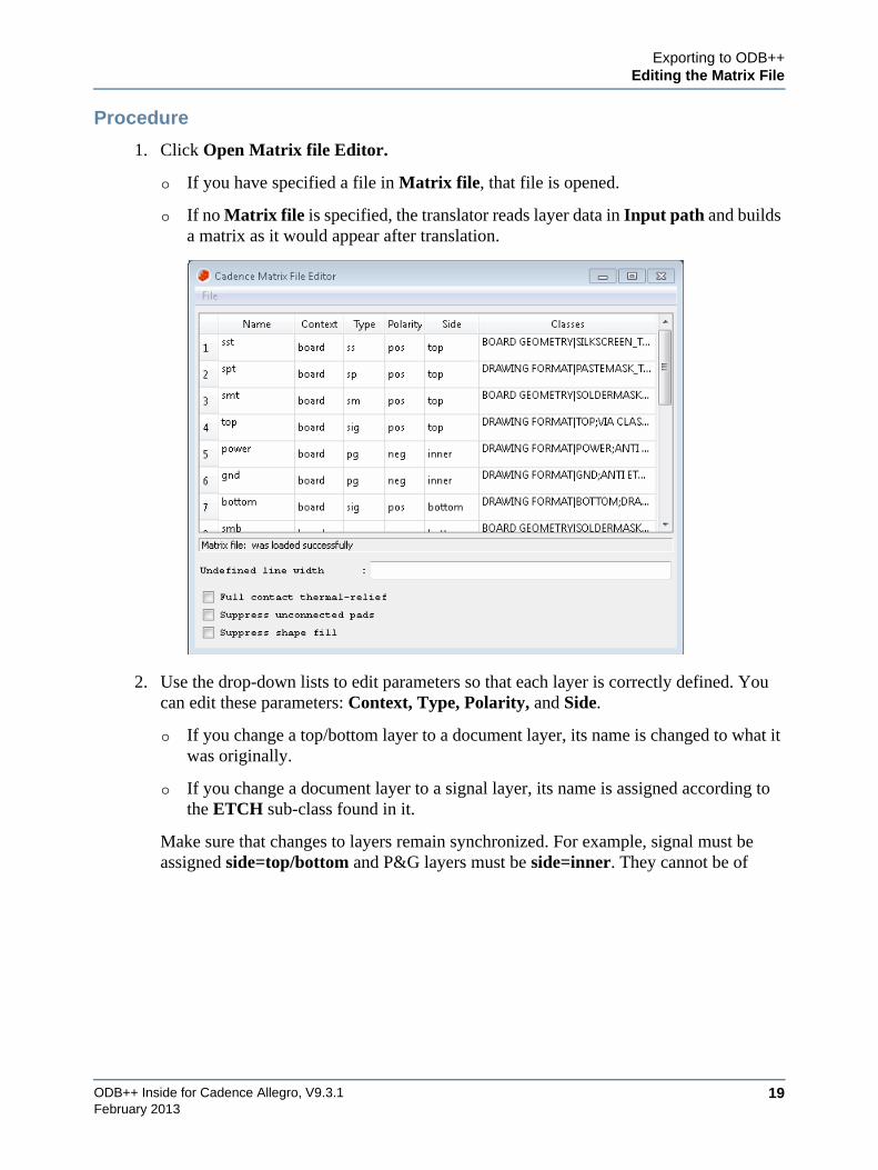
1. Click Open Matrix file Editor.
o If you have specified a file in Matrix file, that file is opened.
o If no Matrix file is specified, the translator reads layer data in Input path and builds a matrix as it would appear after translation.
2. Use the drop-down lists to edit parameters so that each layer is correctly defined. You can edit these parameters: Context, Type, Polarity, and Side.
o If you change a top/bottom layer to a document layer, its name is changed to what it was originally.
o If you change a document layer to a signal layer, its name is assigned according to the ETCH sub-class found in it.
Make sure that changes to layers remain synchronized. For example, signal must be assigned side=top/bottom and P&G layers must be side=inner. They cannot be of
ODB++ Inside for Cadence Allegro, V9.3.120
Exporting to ODB++Editing the Matrix File
February 2013
context misc. Document layers must be assigned side=auto and polarity=pos. Unsynchronized data causes incorrect translation.
3. Select File > Save to save the corrections. You can specify the edited matrix file in Matrix file so that the translation creates layers according to the file.
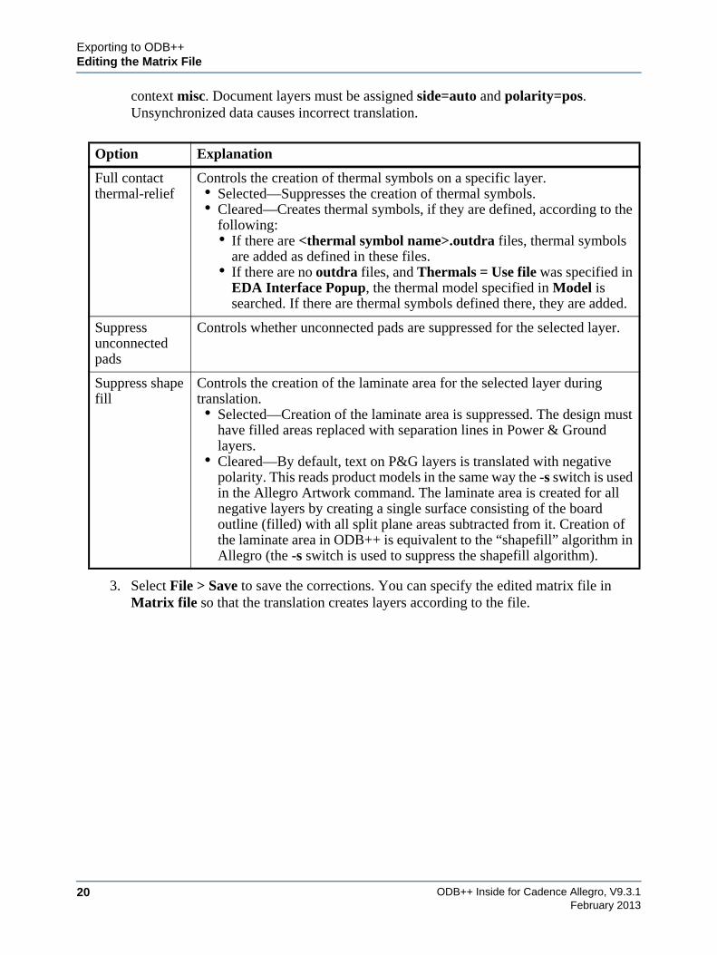
Option Explanation
Full contact thermal-relief
Controls the creation of thermal symbols on a specific layer.• Selected—Suppresses the creation of thermal symbols.• Cleared—Creates thermal symbols, if they are defined, according to the
following:• If there are <thermal symbol name>.outdra files, thermal symbols
are added as defined in these files.• If there are no outdra files, and Thermals = Use file was specified in
EDA Interface Popup, the thermal model specified in Model is searched. If there are thermal symbols defined there, they are added.
Suppress unconnected pads
Controls whether unconnected pads are suppressed for the selected layer.
Suppress shape fill
Controls the creation of the laminate area for the selected layer during translation.• Selected—Creation of the laminate area is suppressed. The design must
have filled areas replaced with separation lines in Power & Ground layers.
• Cleared—By default, text on P&G layers is translated with negative polarity. This reads product models in the same way the -s switch is used in the Allegro Artwork command. The laminate area is created for all negative layers by creating a single surface consisting of the board outline (filled) with all split plane areas subtracted from it. Creation of the laminate area in ODB++ is equivalent to the “shapefill” algorithm in Allegro (the -s switch is used to suppress the shapefill algorithm).
ODB++ Inside for Cadence Allegro, V9.3.1 21February 2013
Chapter 3Viewing the Product Model in ODB++ Viewer
You can use ODB++ Viewer to view the ODB++ product model. You can view the graphic of a step and information about each layer of the step.
Opening ODB++ Viewer . . . . . . . . . . . . . . . . . . . . . . . . . . . . . . . . . . . . . . . . . . . . . . . . . . . 21
Viewing Component or Feature Properties. . . . . . . . . . . . . . . . . . . . . . . . . . . . . . . . . . . . 27
Setting Display Colors . . . . . . . . . . . . . . . . . . . . . . . . . . . . . . . . . . . . . . . . . . . . . . . . . . . . . 30
Opening ODB++ ViewerWhen you run the translator, you can specify that the ODB++ Viewer be opened when the translation completes.
Procedure
1. Start the ODB++ translator.
2. In the Specifying File Options and Output Options page of the wizard, set Open ODB++ viewer = Yes.
3. Perform the translation.
ODB++ Inside for Cadence Allegro, V9.3.122
Viewing the Product Model in ODB++ ViewerOpening ODB++ Viewer
February 2013
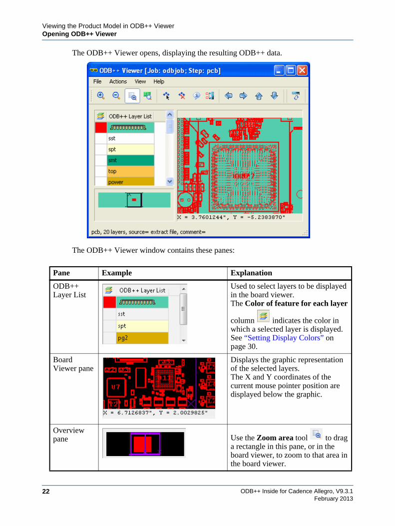
The ODB++ Viewer opens, displaying the resulting ODB++ data.
The ODB++ Viewer window contains these panes:
Pane Example Explanation
ODB++ Layer List
Used to select layers to be displayed in the board viewer.The Color of feature for each layer
column indicates the color in which a selected layer is displayed. See “Setting Display Colors” on page 30.
Board Viewer pane
Displays the graphic representation of the selected layers.The X and Y coordinates of the current mouse pointer position are displayed below the graphic.
Overview pane Use the Zoom area tool to drag
a rectangle in this pane, or in the board viewer, to zoom to that area in the board viewer.
Viewing the Product Model in ODB++ ViewerOpening ODB++ Viewer
ODB++ Inside for Cadence Allegro, V9.3.1 23February 2013
4. Click the Toggle Units tool on the toolbar to toggle the measurement units displayed in the X and Y coordinates under the board viewer, and for the Measure tool, between inches and mm.
5. Select one or more layers in the ODB++ Layer List to display them in the board viewer.
6. Use the menu options and shortcuts to view the step:
o “File Menu Options” on page 23
o “Actions Menu Options” on page 24
o “View Menu Options” on page 24
o “Help Menu Options” on page 25
o “Board Viewer Right-Click Menu Options” on page 25
o “Board Viewer Shortcuts” on page 26
Related topics
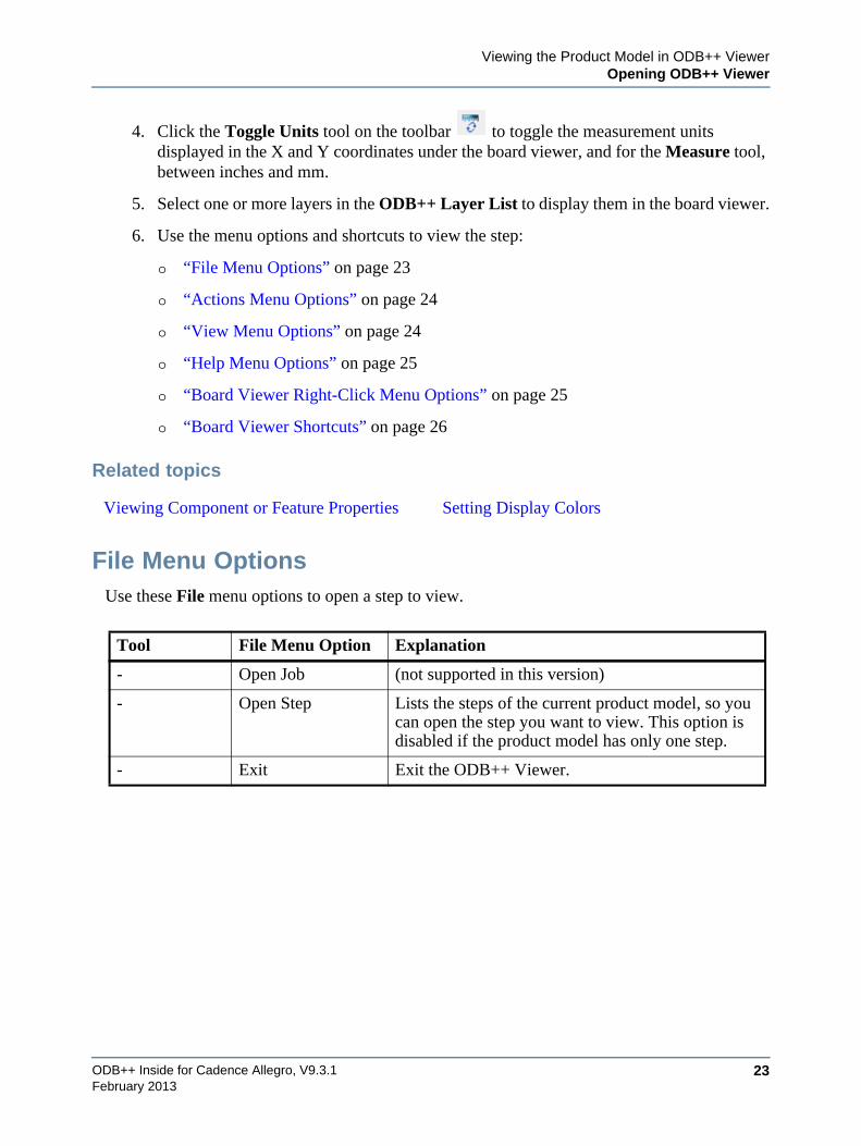
File Menu OptionsUse these File menu options to open a step to view.
Viewing Component or Feature Properties Setting Display Colors
Tool File Menu Option Explanation
- Open Job (not supported in this version)
- Open Step Lists the steps of the current product model, so you can open the step you want to view. This option is disabled if the product model has only one step.
- Exit Exit the ODB++ Viewer.
ODB++ Inside for Cadence Allegro, V9.3.124
Viewing the Product Model in ODB++ ViewerOpening ODB++ Viewer
February 2013
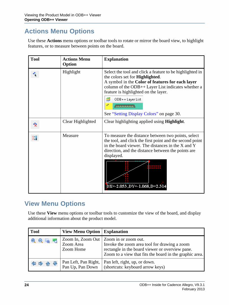
Actions Menu OptionsUse these Actions menu options or toolbar tools to rotate or mirror the board view, to highlight features, or to measure between points on the board.
View Menu OptionsUse these View menu options or toolbar tools to customize the view of the board, and display additional information about the product model.
Tool Actions Menu Option
Explanation
Highlight Select the tool and click a feature to be highlighted in the colors set for Highlighted.A symbol in the Color of features for each layer column of the ODB++ Layer List indicates whether a feature is highlighted on the layer.
See “Setting Display Colors” on page 30.
Clear Highlighted Clear highlighting applied using Highlight.
Measure To measure the distance between two points, select the tool, and click the first point and the second point in the board viewer. The distances in the X and Y direction, and the distance between the points are displayed.
Tool View Menu Option Explanation
Zoom In, Zoom OutZoom AreaZoom Home
Zoom in or zoom out.Invoke the zoom area tool for drawing a zoom rectangle in the board viewer or overview pane.Zoom to a view that fits the board in the graphic area.
Pan Left, Pan Right, Pan Up, Pan Down
Pan left, right, up, or down.(shortcuts: keyboard arrow keys)
Viewing the Product Model in ODB++ ViewerOpening ODB++ Viewer
ODB++ Inside for Cadence Allegro, V9.3.1 25February 2013
Help Menu OptionsUse these Help menu options to view information about ODB++ Viewer.
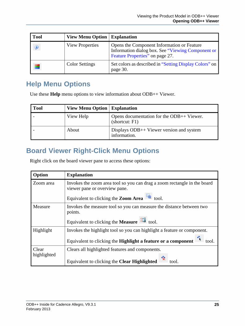
Board Viewer Right-Click Menu OptionsRight click on the board viewer pane to access these options:
View Properties Opens the Component Information or Feature Information dialog box. See “Viewing Component or Feature Properties” on page 27.
Color Settings Set colors as described in “Setting Display Colors” on page 30.
Tool View Menu Option Explanation
- View Help Opens documentation for the ODB++ Viewer. (shortcut: F1)
- About Displays ODB++ Viewer version and system information.
Option Explanation
Zoom area Invokes the zoom area tool so you can drag a zoom rectangle in the board viewer pane or overview pane.
Equivalent to clicking the Zoom Area tool.
Measure Invokes the measure tool so you can measure the distance between two points.
Equivalent to clicking the Measure tool.
Highlight Invokes the highlight tool so you can highlight a feature or component.
Equivalent to clicking the Highlight a feature or a component tool.
Clear highlighted
Clears all highlighted features and components.
Equivalent to clicking the Clear Highlighted tool.
Tool View Menu Option Explanation
ODB++ Inside for Cadence Allegro, V9.3.126
Viewing the Product Model in ODB++ ViewerOpening ODB++ Viewer
February 2013
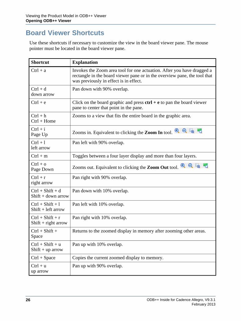
Board Viewer ShortcutsUse these shortcuts if necessary to customize the view in the board viewer pane. The mouse pointer must be located in the board viewer pane.
Shortcut Explanation
Ctrl + a Invokes the Zoom area tool for one actuation. After you have dragged a rectangle in the board viewer pane or in the overview pane, the tool that was previously in effect is in effect.
Ctrl + ddown arrow
Pan down with 90% overlap.
Ctrl + e Click on the board graphic and press ctrl + e to pan the board viewer pane to center that point in the pane.
Ctrl + hCtrl + Home
Zooms to a view that fits the entire board in the graphic area.
Ctrl + iPage Up Zooms in. Equivalent to clicking the Zoom In tool.
Ctrl + lleft arrow
Pan left with 90% overlap.
Ctrl + m Toggles between a four layer display and more than four layers.
Ctrl + oPage Down Zooms out. Equivalent to clicking the Zoom Out tool.
Ctrl + rright arrow
Pan right with 90% overlap.
Ctrl + Shift + dShift + down arrow
Pan down with 10% overlap.
Ctrl + Shift + lShift + left arrow
Pan left with 10% overlap.
Ctrl + Shift + rShift + right arrow
Pan right with 10% overlap.
Ctrl + Shift + Space
Returns to the zoomed display in memory after zooming other areas.
Ctrl + Shift + uShift + up arrow
Pan up with 10% overlap.
Ctrl + Space Copies the current zoomed display to memory.
Ctrl + uup arrow
Pan up with 90% overlap.
Viewing the Product Model in ODB++ ViewerViewing Component or Feature Properties
ODB++ Inside for Cadence Allegro, V9.3.1 27February 2013
Viewing Component or Feature PropertiesYou can view properties of a component or feature that is highlighted in the graphic.
Procedure
1. Open ODB++ Viewer as described in “Opening ODB++ Viewer” on page 21.
2. In the ODB++ Layers List, display the layer containing the components or features you want to view.
3. To view properties of a feature, highlight a feature in the graphic and click View
Properties .
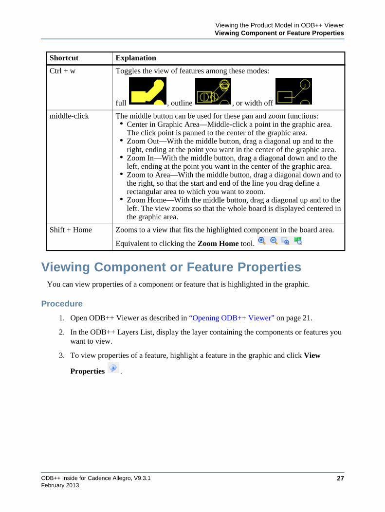
Ctrl + w Toggles the view of features among these modes:
full , outline , or width off
middle-click The middle button can be used for these pan and zoom functions:• Center in Graphic Area—Middle-click a point in the graphic area.
The click point is panned to the center of the graphic area.• Zoom Out—With the middle button, drag a diagonal up and to the
right, ending at the point you want in the center of the graphic area.• Zoom In—With the middle button, drag a diagonal down and to the
left, ending at the point you want in the center of the graphic area.• Zoom to Area—With the middle button, drag a diagonal down and to
the right, so that the start and end of the line you drag define a rectangular area to which you want to zoom.
• Zoom Home—With the middle button, drag a diagonal up and to the left. The view zooms so that the whole board is displayed centered in the graphic area.
Shift + Home Zooms to a view that fits the highlighted component in the board area.
Equivalent to clicking the Zoom Home tool.
Shortcut Explanation
ODB++ Inside for Cadence Allegro, V9.3.128
Viewing the Product Model in ODB++ ViewerViewing Component or Feature Properties
February 2013
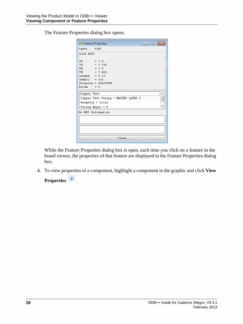
The Feature Properties dialog box opens.
While the Feature Properties dialog box is open, each time you click on a feature in the board viewer, the properties of that feature are displayed in the Feature Properties dialog box.
4. To view properties of a component, highlight a component in the graphic and click View
Properties .
Viewing the Product Model in ODB++ ViewerViewing Component or Feature Properties
ODB++ Inside for Cadence Allegro, V9.3.1 29February 2013
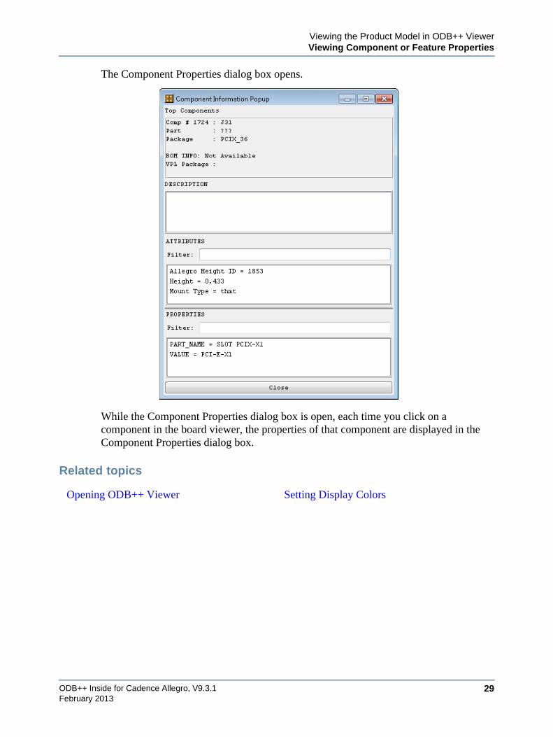
The Component Properties dialog box opens.
While the Component Properties dialog box is open, each time you click on a component in the board viewer, the properties of that component are displayed in the Component Properties dialog box.
Related topics
Opening ODB++ Viewer Setting Display Colors
ODB++ Inside for Cadence Allegro, V9.3.130
Viewing the Product Model in ODB++ ViewerSetting Display Colors
February 2013
Setting Display ColorsYou can set the colors that uses to display items in the board viewer. You can save color specifications in a file. Where colors overlap, they are mixed.
Procedure
1. Open ODB++ Viewer as described in “Opening ODB++ Viewer” on page 21.
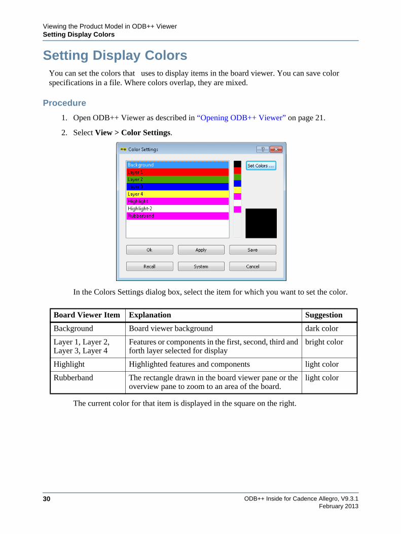
2. Select View > Color Settings.
In the Colors Settings dialog box, select the item for which you want to set the color.
The current color for that item is displayed in the square on the right.
Board Viewer Item Explanation Suggestion
Background Board viewer background dark color
Layer 1, Layer 2, Layer 3, Layer 4
Features or components in the first, second, third and forth layer selected for display
bright color
Highlight Highlighted features and components light color
Rubberband The rectangle drawn in the board viewer pane or the overview pane to zoom to an area of the board.
light color
Viewing the Product Model in ODB++ ViewerSetting Display Colors
ODB++ Inside for Cadence Allegro, V9.3.1 31February 2013
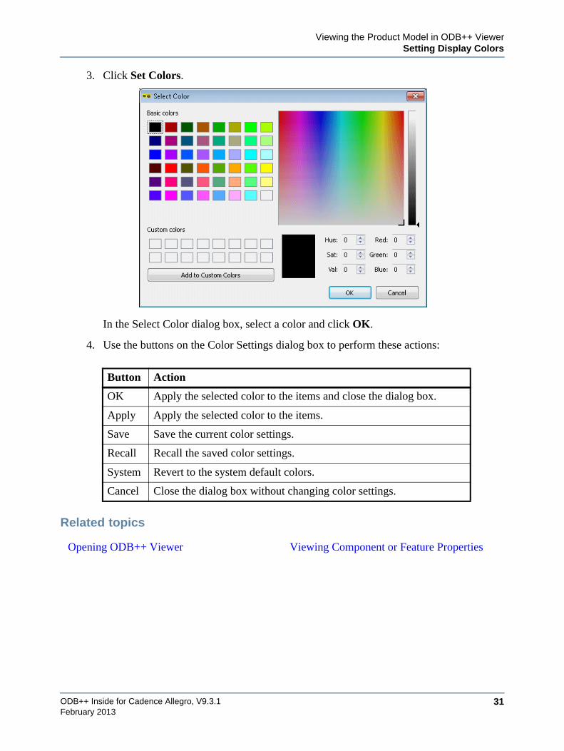
3. Click Set Colors.
In the Select Color dialog box, select a color and click OK.
4. Use the buttons on the Color Settings dialog box to perform these actions:
Related topics
Button Action
OK Apply the selected color to the items and close the dialog box.
Apply Apply the selected color to the items.
Save Save the current color settings.
Recall Recall the saved color settings.
System Revert to the system default colors.
Cancel Close the dialog box without changing color settings.
Opening ODB++ Viewer Viewing Component or Feature Properties
ODB++ Inside for Cadence Allegro, V9.3.132
Viewing the Product Model in ODB++ ViewerSetting Display Colors
February 2013
ODB++ Inside for Cadence Allegro, V9.3.1 33February 2013
Chapter 4System Administrator Notes
Running the Translator from Design Workbench . . . . . . . . . . . . . . . . . . . . . . . . . . . . . . 33
Setting Configuration Parameters . . . . . . . . . . . . . . . . . . . . . . . . . . . . . . . . . . . . . . . . . . . 34
Setting Environment Variables . . . . . . . . . . . . . . . . . . . . . . . . . . . . . . . . . . . . . . . . . . . . . 39
Configuring a Thermal Model . . . . . . . . . . . . . . . . . . . . . . . . . . . . . . . . . . . . . . . . . . . . . . 39
Generating the Extraction Files . . . . . . . . . . . . . . . . . . . . . . . . . . . . . . . . . . . . . . . . . . . . . 42
Using Command Line Parameters . . . . . . . . . . . . . . . . . . . . . . . . . . . . . . . . . . . . . . . . . . . 46
Supported Features . . . . . . . . . . . . . . . . . . . . . . . . . . . . . . . . . . . . . . . . . . . . . . . . . . . . . . . 49
Release Notes . . . . . . . . . . . . . . . . . . . . . . . . . . . . . . . . . . . . . . . . . . . . . . . . . . . . . . . . . . . . 53
Running the Translator from Design WorkbenchWhen Allegro is to be launched from the Allegro Design Workbench, environment variable PCBDW_USER_PATH must be set when ODB++ Inside is installed.
Procedure
1. Locate the Allegro Design Workbench launch wrapper file adwstart.bat. This file is typically located under the install tree.
2. Edit adwstart.bat to include this line:
set PCBDW_USER_PATH=<path to ODB++ Inside>\nv\bin
where <path to ODB++ Inside> is the path to the ODB++ Inside module, typically C:\MentorGraphics\Allegro Export ODB++.
ODB++ Inside for Cadence Allegro, V9.3.134
System Administrator NotesSetting Configuration Parameters
February 2013
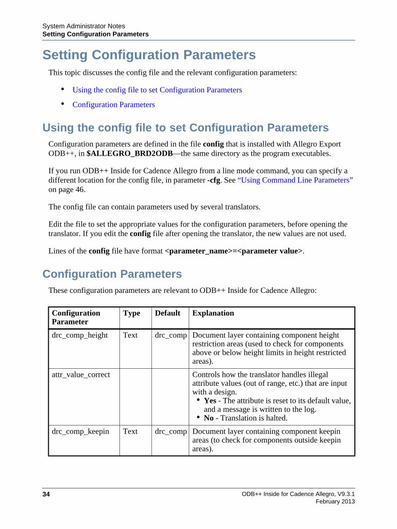
Setting Configuration ParametersThis topic discusses the config file and the relevant configuration parameters:
• Using the config file to set Configuration Parameters
• Configuration Parameters
Using the config file to set Configuration ParametersConfiguration parameters are defined in the file config that is installed with Allegro Export ODB++, in $ALLEGRO_BRD2ODB—the same directory as the program executables.
If you run ODB++ Inside for Cadence Allegro from a line mode command, you can specify a different location for the config file, in parameter -cfg. See “Using Command Line Parameters” on page 46.
The config file can contain parameters used by several translators.
Edit the file to set the appropriate values for the configuration parameters, before opening the translator. If you edit the config file after opening the translator, the new values are not used.
Lines of the config file have format <parameter_name>=<parameter value>.
Configuration ParametersThese configuration parameters are relevant to ODB++ Inside for Cadence Allegro:
Configuration Parameter
Type Default Explanation
drc_comp_height Text drc_comp Document layer containing component height restriction areas (used to check for components above or below height limits in height restricted areas).
attr_value_correct Controls how the translator handles illegal attribute values (out of range, etc.) that are input with a design.• Yes - The attribute is reset to its default value,
and a message is written to the log.• No - Translation is halted.
drc_comp_keepin Text drc_comp Document layer containing component keepin areas (to check for components outside keepin areas).
System Administrator NotesSetting Configuration Parameters
ODB++ Inside for Cadence Allegro, V9.3.1 35February 2013
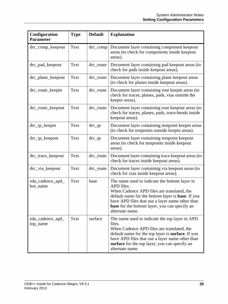
drc_comp_keepout Text drc_comp Document layer containing component keepout areas (to check for components inside keepout areas).
drc_pad_keepout Text drc_route Document layer containing pad keepout areas (to check for pads inside keepout areas).
drc_plane_keepout Text drc_route Document layer containing plane keepout areas (to check for planes inside keepout areas).
drc_route_keepin Text drc_route Document layer containing rout keepin areas (to check for traces, planes, pads, vias outside the keepin areas).
drc_route_keepout Text drc_route Document layer containing rout keepout areas (to check for traces, planes, pads, trace-bends inside keepout areas).
drc_tp_keepin Text drc_tp Document layer containing testpoint keepin areas (to check for testpoints outside keepin areas).
drc_tp_keepout Text drc_tp Document layer containing testpoint keepout areas (to check for testpoints inside keepout areas).
drc_trace_keepout Text drc_route Document layer containing trace keepout areas (to check for traces inside keepout areas).
drc_via_keepout Text drc_route Document layer containing via keepout areas (to check for vias inside keepout areas).
eda_cadence_apd_bot_name
Text base The name used to indicate the bottom layer in APD files.When Cadence APD files are translated, the default name for the bottom layer is base. If you have APD files that use a layer name other than base for the bottom layer, you can specify an alternate name.
eda_cadence_apd_top_name
Text surface The name used to indicate the top layer in APD files.When Cadence APD files are translated, the default name for the top layer is surface. If you have APD files that use a layer name other than surface for the top layer, you can specify an alternate name.
Configuration Parameter
Type Default Explanation
ODB++ Inside for Cadence Allegro, V9.3.136
System Administrator NotesSetting Configuration Parameters
February 2013
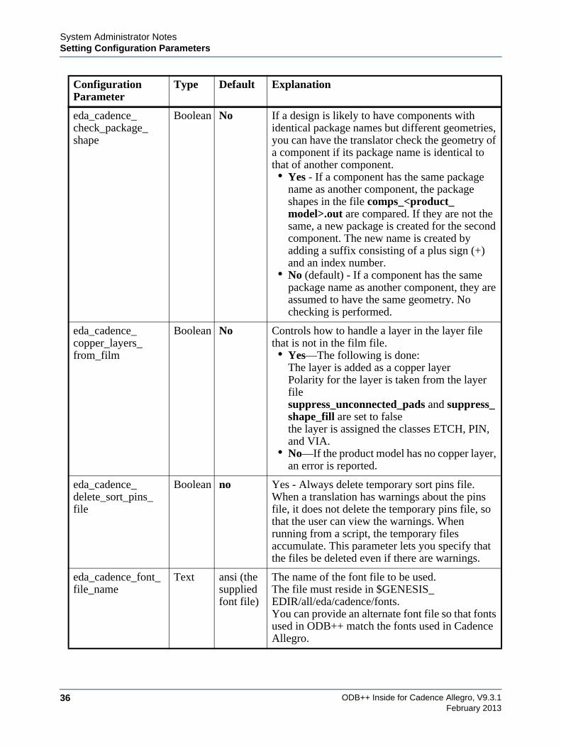
eda_cadence_check_package_shape
Boolean No If a design is likely to have components with identical package names but different geometries, you can have the translator check the geometry of a component if its package name is identical to that of another component. • Yes - If a component has the same package
name as another component, the package shapes in the file comps_<product_model>.out are compared. If they are not the same, a new package is created for the second component. The new name is created by adding a suffix consisting of a plus sign (+) and an index number.
• No (default) - If a component has the same package name as another component, they are assumed to have the same geometry. No checking is performed.
eda_cadence_copper_layers_from_film
Boolean No Controls how to handle a layer in the layer file that is not in the film file.• Yes—The following is done:
The layer is added as a copper layerPolarity for the layer is taken from the layer filesuppress_unconnected_pads and suppress_shape_fill are set to falsethe layer is assigned the classes ETCH, PIN, and VIA.
• No—If the product model has no copper layer, an error is reported.
eda_cadence_delete_sort_pins_file
Boolean no Yes - Always delete temporary sort pins file.When a translation has warnings about the pins file, it does not delete the temporary pins file, so that the user can view the warnings. When running from a script, the temporary files accumulate. This parameter lets you specify that the files be deleted even if there are warnings.
eda_cadence_font_file_name
Text ansi (the supplied font file)
The name of the font file to be used. The file must reside in $GENESIS_EDIR/all/eda/cadence/fonts.You can provide an alternate font file so that fonts used in ODB++ match the fonts used in Cadence Allegro.
Configuration Parameter
Type Default Explanation
System Administrator NotesSetting Configuration Parameters
ODB++ Inside for Cadence Allegro, V9.3.1 37February 2013
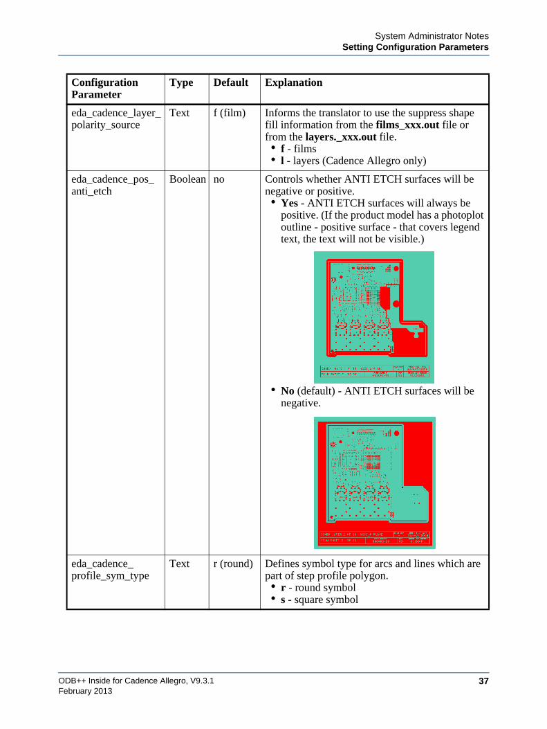
eda_cadence_layer_polarity_source
Text f (film) Informs the translator to use the suppress shape fill information from the films_xxx.out file or from the layers._xxx.out file.• f - films• l - layers (Cadence Allegro only)
eda_cadence_pos_anti_etch
Boolean no Controls whether ANTI ETCH surfaces will be negative or positive.• Yes - ANTI ETCH surfaces will always be
positive. (If the product model has a photoplot outline - positive surface - that covers legend text, the text will not be visible.)
• No (default) - ANTI ETCH surfaces will be negative.
eda_cadence_profile_sym_type
Text r (round) Defines symbol type for arcs and lines which are part of step profile polygon.• r - round symbol• s - square symbol
Configuration Parameter
Type Default Explanation
ODB++ Inside for Cadence Allegro, V9.3.138
System Administrator NotesSetting Configuration Parameters
February 2013
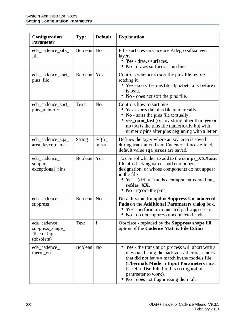
eda_cadence_silk_fill
Boolean No Fills surfaces on Cadence Allegro silkscreen layers.• Yes - draws surfaces.• No - draws surfaces as outlines.
eda_cadence_sort_pins_file
Boolean Yes Controls whether to sort the pins file before reading it.• Yes - sorts the pins file alphabetically before it
is read.• No - does not sort the pins file.
eda_cadence_sort_pins_numeric
Text No Controls how to sort pins.• Yes - sorts the pins file numerically.• No - sorts the pins file textually.• yes_num_last (or any string other than yes or
no) sorts the pins file numerically but with numeric pins after pins beginning with a letter.
eda_cadence_sqa_area_layer_name
String SQA_areas
Defines the layer where an sqa area is saved during translation from Cadence. If not defined, default value sqa_areas are saved.
eda_cadence_support_exceptional_pins
Boolean Yes To control whether to add to the comps_XXX.out file pins lacking names and component designation, or whose components do not appear in the file.• Yes - (default) adds a component named no_
refdes+XX.• No - ignore the pins.
eda_cadence_suppress
Boolean No Default value for option Suppress Unconnected Pads on the Additional Parameters dialog box.• Yes - perform unconnected pad suppression.• No - do not suppress unconnected pads.
eda_cadence_suppress_shape_fill_setting (obsolete)
Text f Obsolete - replaced by the Suppress shape fill option of the Cadence Matrix File Editor.
eda_cadence_therm_err
Boolean No • Yes - the translation process will abort with a message listing the padstack / thermal names that did not have a match in the models file. (Thermals Mode in Input Parameters must be set to Use File for this configuration parameter to work).
• No - does not flag missing thermals.
Configuration Parameter
Type Default Explanation
System Administrator NotesSetting Environment Variables
ODB++ Inside for Cadence Allegro, V9.3.1 39February 2013
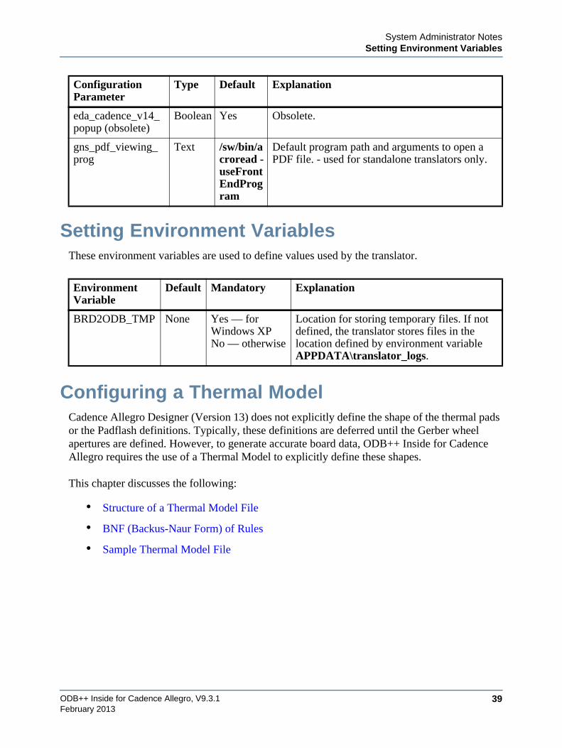
Setting Environment VariablesThese environment variables are used to define values used by the translator.
Configuring a Thermal ModelCadence Allegro Designer (Version 13) does not explicitly define the shape of the thermal pads or the Padflash definitions. Typically, these definitions are deferred until the Gerber wheel apertures are defined. However, to generate accurate board data, ODB++ Inside for Cadence Allegro requires the use of a Thermal Model to explicitly define these shapes.
This chapter discusses the following:
• Structure of a Thermal Model File
• BNF (Backus-Naur Form) of Rules
• Sample Thermal Model File
eda_cadence_v14_popup (obsolete)
Boolean Yes Obsolete.
gns_pdf_viewing_prog
Text /sw/bin/acroread -useFrontEndProgram
Default program path and arguments to open a PDF file. - used for standalone translators only.
Environment Variable
Default Mandatory Explanation
BRD2ODB_TMP None Yes — for Windows XPNo — otherwise
Location for storing temporary files. If not defined, the translator stores files in the location defined by environment variable APPDATA\translator_logs.
Configuration Parameter
Type Default Explanation
ODB++ Inside for Cadence Allegro, V9.3.140
System Administrator NotesConfiguring a Thermal Model
February 2013
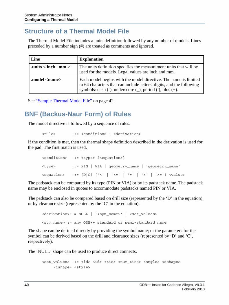
Structure of a Thermal Model FileThe Thermal Model File includes a units definition followed by any number of models. Lines preceded by a number sign (#) are treated as comments and ignored.
See “Sample Thermal Model File” on page 42.
BNF (Backus-Naur Form) of RulesThe model directive is followed by a sequence of rules.
<rule> ::= <condition> : <derivation>
If the condition is met, then the thermal shape definition described in the derivation is used for the pad. The first match is used.
<condition> ::= <type> {<equation>}
<type> ::= PIN | VIA | geometry_name | 'geometry_name'
<equation> ::= [D|C] ['<' | '<=' | '=' | '>' | '>='] <value>
The padstack can be compared by its type (PIN or VIA) or by its padstack name. The padstack name may be enclosed in quotes to accommodate padstacks named PIN or VIA.
The padstack can also be compared based on drill size (represented by the ‘D’ in the equation), or by clearance size (represented by the ‘C’ in the equation).
<derivation>::= NULL | '<sym_name>' | <set_values>
<sym_name>::= any ODB++ standard or semi-standard name
The shape can be defined directly by providing the symbol name; or the parameters for the symbol can be derived based on the drill and clearance sizes (represented by ‘D’ and ‘C’, respectively).
The ‘NULL’ shape can be used to produce direct connects.
<set_values> ::= <id> <id> <tie> <num_ties> <angle> <oshape>
<ishape> <style>
Line Explanation
.units < inch | mm > The units definition specifies the measurement units that will be used for the models. Legal values are inch and mm.
.model <name> Each model begins with the model directive. The name is limited to 64 characters that can include letters, digits, and the following symbols: dash (-), underscore (_), period (.), plus (+).
System Administrator NotesConfiguring a Thermal Model
ODB++ Inside for Cadence Allegro, V9.3.1 41February 2013
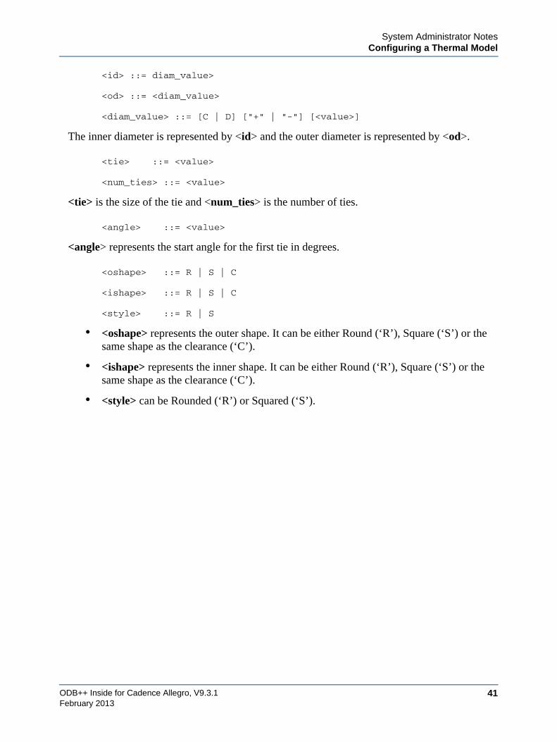
<id> ::= diam_value>
<od> ::= <diam_value>
<diam_value> ::= [C | D] ["+" | "-"] [<value>]
The inner diameter is represented by <id> and the outer diameter is represented by <od>.
<tie> ::= <value>
<num_ties> ::= <value>
<tie> is the size of the tie and <num_ties> is the number of ties.
<angle> ::= <value>
<angle> represents the start angle for the first tie in degrees.
<oshape> ::= R | S | C
<ishape> ::= R | S | C
<style> ::= R | S
• <oshape> represents the outer shape. It can be either Round (‘R’), Square (‘S’) or the same shape as the clearance (‘C’).
• <ishape> represents the inner shape. It can be either Round (‘R’), Square (‘S’) or the same shape as the clearance (‘C’).
• <style> can be Rounded (‘R’) or Squared (‘S’).
ODB++ Inside for Cadence Allegro, V9.3.142
System Administrator NotesGenerating the Extraction Files
February 2013
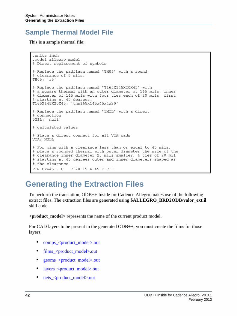
Sample Thermal Model FileThis is a sample thermal file:
Generating the Extraction FilesTo perform the translation, ODB++ Inside for Cadence Allegro makes use of the following extract files. The extraction files are generated using $ALLEGRO_BRD2ODB/valor_ext.il skill code.
<product_model> represents the name of the current product model.
For CAD layers to be present in the generated ODB++, you must create the films for those layers.
• comps_<product_model>.out
• films_<product_model>.out
• geoms_<product_model>.out
• layers_<product_model>.out
• nets_<product_model>.out
.units inch
.model allegro_model# Direct replacement of symbols
# Replace the padflash named "TH05" with a round# clearance of 5 mils. TH05: 'r5'
# Replace the padflash named "T165X145X20X45" with# a square thermal with an outer diameter of 165 mils, inner# diameter of 145 mils with four ties each of 20 mils, first# starting at 45 degrees.T165X145X20X45: 'ths165x145x45x4x20'
# Replace the padflash named "5MIL" with a direct# connection5MIL: 'null'
# calculated values
# Place a direct connect for all VIA padsVIA: NULL
# For pins with a clearance less than or equal to 45 mils,# place a rounded thermal with outer diameter the size of the# clearance inner diameter 20 mils smaller, 4 ties of 20 mil# starting at 45 degrees outer and inner diameters shaped as# the clearancePIN C<=45 : C C-20 15 4 45 C C R
System Administrator NotesGenerating the Extraction Files
ODB++ Inside for Cadence Allegro, V9.3.1 43February 2013
• pads_<product_model>.out
• pins_<product_model>.out
• props_<product_model>.out
• tech_<product_model>.out
comps_<product_model>.outContains the outline shape of the components. In ODB++, components must each be defined as a single closed shape, therefore the PLACE_BOUND outlines are typically used.
Pins lacking names and component designations, or whose components are not found in the comp_<product_model>.out file, might be either mechanical pins or testpoints, and should not be ignored. The eda_cadence_support_exceptional_pins configuration parameter handles such pins.
If a design is likely to have components with identical package names but different geometries, you can have the translator check the geometry of a component if its package name is identical to that of another component. If configuration parameter eda_cadence_check_package_shape is set to yes, the package shapes in the file comps_<product_model>.out are compared for components having identical package names. If a component is found to have a different geometry from a component with the same package name, a new package name is created for the component. The name is generated from the existing package name by adding a suffix consisting of a plus sign (+) and a number. See “Setting Configuration Parameters” on page 34.
films_<product_model>.outContains the artwork information from Allegro.
The following rules are used to determine which film to apply to a layer. If these rules do not produce the desired results, you can create a matrix file to define the layers. See “Editing the Matrix File” on page 18.
• If there is only one film in the file with class = ETCH and subclass = <layer name>, this film is used.
• Otherwise, if there are multiple films with ETCH!<layer name>, and one of the films has the same name as the layer, this film is used. (A warning is issued if there are multiple films with ETCH!<layer name>.)
• Otherwise, if only one of the films has only one ETCH!<layer name> class, this film is used.
• Otherwise, the following films are rejected, and the first remaining film in the file having ETCH!<layer name> is used:
ODB++ Inside for Cadence Allegro, V9.3.144
System Administrator NotesGenerating the Extraction Files
February 2013
o a film with more than ten classes
o a film with keepin / keepout classes
o a film with silkscreen / soldermask / solderpaste classes
See “layers_<product_model>.out” on page 44.
If there is a layer in the layer file that is not listed in the film file, you can use configuration parameter eda_cadence_copper_layers_from_films to translate the layer. If eda_cadence_copper_layers_from_films = yes, and there is a layer in the layer file but not in the film file, the following is done:
• The layer is added as a copper layer
• Polarity for the layer is taken from the layer file
• suppress_unconnected_pads and suppress_shape_fill are set to false
• the layer is assigned the classes ETCH, PIN, and VIA.
Because an empty films file causes the translation to fail, the valor_ext.il import script checks whether films_<product_model>.out is empty and prompts the user to check the artworks file and extract again.
geoms_<product_model>.outThe graphical data describing feature placement.
The extraction program valor.ext.il adds the field FILLET in the geoms file. The attribute .tear_drop is added to components having CLASS = ETCH and FILLET = yes.
layers_<product_model>.outProvides information on the order of the physical layers.
For an explanation of how films listed in the film file are added to the appropriate layers, see “films_<product_model>.out” on page 43.
nets_<product_model>.outThis file is optional and is not required for translation. It contains two types of information on nets: classes and properties. Allegro declares three types of class: spacing, physical, and electrical. Every net may connect/have any combination of triplet of spacing, physical, and electrical classes, if any. The classes are defined in the technology file. It also contains some net properties, such as impedance.
System Administrator NotesGenerating the Extraction Files
ODB++ Inside for Cadence Allegro, V9.3.1 45February 2013
The property NO_TEST was added to the nets_<product_model>.out file. A net with a value of Yes for this property will have the attribute .testpoint_count set to 0.
pads_<product_model>.outContains information on the padstacks in the product model.
The Allegro BRD file currently does not contain information on the Padshapes. Therefore, the names that appear in the Padflash field, must be defined with the Thermal Model. (See “Configuring a Thermal Model” on page 39.)
pins_<product_model>.outContains information on pins and vias.
The translator reads the pins in order of appearance. Therefore, the extract pins file must be sorted in ascending order according to pin number. This is performed automatically when invoked from Cadence Allegro.
Two fields added to pins_<product_model>.out during translation support the V15.2 drill tolerances of Cadence Allegro. They are DRILL_HOLE_POSTOL and DRILL_HOLE_NEGTOL. They enable reading maximum and minimum drill tolerance values.
props_<product_model>.outContains additional component property information. This file is optional. This was originally added so that users could read additional component properties directly into ODB++. Users requiring the extraction of additional properties can manually add them to the view file.
tech_<product_model>.outThis file is an optional ASCII file that contains Allegro/APD parameter and constraint data. By using the tech file, a user can apply a uniform set of design rules and constraints to designs that share the same set of design rules and constraints.
• User Units
• Drawing Parameters
• Layout Cross Section Parameters
• Spacing Constraints (Part of the spacing constraints are the clearances rules.)
• Physical Constraints
• Electrical Constraints
ODB++ Inside for Cadence Allegro, V9.3.146
System Administrator NotesUsing Command Line Parameters
February 2013
• User Property Definitions
From Cadence Allegro version 16.0, tech files are generated in XML format. ODB++ Inside for Cadence Allegro can identify whether the technology file is of the new XML-based format or of the old format, and can read the file in either format.
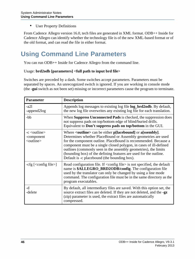
Using Command Line ParametersYou can run ODB++ Inside for Cadence Allegro from the command line.
Usage: brd2odb [parameters] <full path to input brd file>
Switches are preceded by a dash. Some switches accept parameters. Parameters must be separated by spaces. An unrecognized switch is ignored. If you are working in console mode (the -gui switch as not been set) missing or incorrect parameters cause the program to terminate.
Parameter Description
-a2l-append2log
Appends log messages to existing log file log_brd2odb. By default, the new log file overwrites any existing log file for each translation.
-bb When Suppress Unconnected Pads is checked, the suppression does not suppress pads on top/bottom edge of blind/buried drills.Equivalent to Don’t suppress pads on top/bottom in the GUI.
-c <outline>-component <outline>
Where <outline> can be either p[lacebound] or a[ssembly]. Determines whether PlaceBound or Assembly geometries are used for the component outline. PlaceBound is recommended. Because a component must be a single closed polygon, in cases of ill-defined outlines (commonly seen in the assembly geometries), the limits (bounding box) of the defining features are used for the outline. Default is -c placebound (the bounding box).
-cfg [<config file>] Read configuration file. If <config file> is not specified, the default name is $ALLEGRO_BRD2ODB/config. The configuration file used by the translator can only be changed by using a line mode command. The configuration file must be in the same directory as the program executables.
-d-delete
By default, all intermediary files are saved. With this option set, the source extract files are deleted. If they are not deleted, and the -gz (zip) parameter is used, the extract files are automatically compressed.
System Administrator NotesUsing Command Line Parameters
ODB++ Inside for Cadence Allegro, V9.3.1 47February 2013
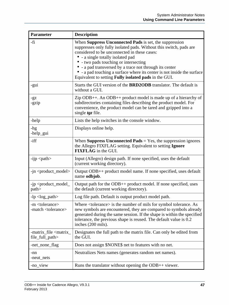
-fi When Suppress Unconnected Pads is set, the suppression suppresses only fully isolated pads. Without this switch, pads are considered to be unconnected in these cases:• - a single totally isolated pad• - two pads touching or intersecting• - a pad transversed by a trace not through its center• - a pad touching a surface where its center is not inside the surface
Equivalent to setting Fully isolated pads in the GUI.
-gui Starts the GUI version of the BRD2ODB translator. The default is without a GUI.
-gz-gzip
Zip ODB++. An ODB++ product model is made up of a hierarchy of subdirectories containing files describing the product model. For convenience, the product model can be tared and gzipped into a single tgz file.
-help Lists the help switches in the console window.
-hg-help_gui
Displays online help.
-iff When Suppress Unconnected Pads = Yes, the suppression ignores the Allegro FIXFLAG setting. Equivalent to setting Ignore FIXFLAG in the GUI.
-ijp <path> Input (Allegro) design path. If none specified, uses the default (current working directory).
-jn <product_model> Output ODB++ product model name. If none specified, uses default name odbjob.
-jp <product_model_path>
Output path for the ODB++ product model. If none specified, uses the default (current working directory).
-lp <log_path> Log file path. Default is output product model path.
-m <tolerance>-match <tolerance>
Where <tolerance> is the number of mils for symbol tolerance. As new symbols are encountered, they are compared to symbols already generated during the same session. If the shape is within the specified tolerance, the previous shape is reused. The default value is 0.2 inches (200 mils).
-matrix_file <matrix_file_full_path>
Designates the full path to the matrix file. Can only be edited from the GUI.
-net_none_flag Does not assign $NONE$ net to features with no net.
-nn-neut_nets
Neutralizes Nets names (generates random net names).
-no_view Runs the translator without opening the ODB++ viewer.
Parameter Description
ODB++ Inside for Cadence Allegro, V9.3.148
System Administrator NotesUsing Command Line Parameters
February 2013
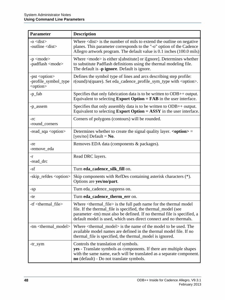
-o <dist>-outline <dist>
Where <dist> is the number of mils to extend the outline on negative planes. This parameter corresponds to the "-o" option of the Cadence Allegro artwork program. The default value is 0.1 inches (100.0 mils)
-p <mode>-padflash <mode>
Where <mode> is either s[ubstitute] or i[gnore]. Determines whether to substitute Padflash definitions using the thermal modeling file. The default is -p ignore. Default is ignore.
-pst <option>-profile_symbol_type <option>
Defines the symbol type of lines and arcs describing step profile: r(ound)/s(quare). Set eda_cadence_profile_sym_type with <option>.
-p_fab Specifies that only fabrication data is to be written to ODB++ output. Equivalent to selecting Export Option = FAB in the user interface.
-p_assem Specifies that only assembly data is to be written to ODB++ output. Equivalent to selecting Export Option = ASSY in the user interface.
-rc-round_corners
Corners of polygons (contours) will be rounded.
-read_sqa <option> Determines whether to create the signal quality layer. <option> = [yes/no] Default = No.
-re-remove_eda
Removes EDA data (components & packages).
-r-read_drc
Read DRC layers.
-sf Turn eda_cadence_silk_fill on.
-skip_refdes <option> Skip components with RefDes containing asterisk characters (*). Options are yes/no/part.
-sp Turn eda_cadence_suppress on.
-te Turn eda_cadence_therm_err on.
-tf <thermal_file> Where <thermal_file> is the full path name for the thermal model file. If the thermal_file is specified, the thermal_model (see parameter -tm) must also be defined. If no thermal file is specified, a default model is used, which uses direct connect and no thermals.
-tm <thermal_model> Where <thermal_model> is the name of the model to be used. The available model names are defined in the thermal model file. If no thermal_file is specified, the thermal_model is ignored.
-tr_sym Controls the translation of symbols.yes - Translate symbols as components. If there are multiple shapes with the same name, each will be translated as a separate component.no (default) - Do not translate symbols.
Parameter Description
System Administrator NotesSupported Features
ODB++ Inside for Cadence Allegro, V9.3.1 49February 2013
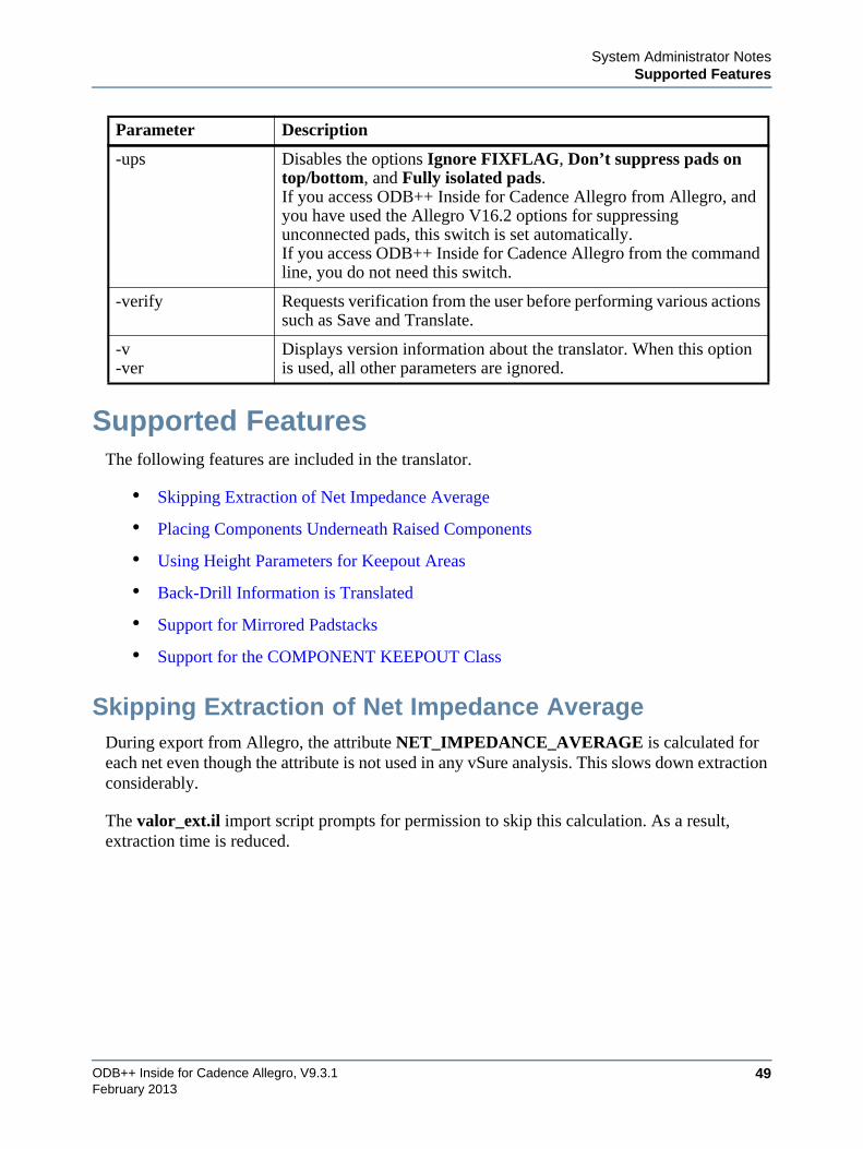
Supported FeaturesThe following features are included in the translator.
• Skipping Extraction of Net Impedance Average
• Placing Components Underneath Raised Components
• Using Height Parameters for Keepout Areas
• Back-Drill Information is Translated
• Support for Mirrored Padstacks
• Support for the COMPONENT KEEPOUT Class
Skipping Extraction of Net Impedance AverageDuring export from Allegro, the attribute NET_IMPEDANCE_AVERAGE is calculated for each net even though the attribute is not used in any vSure analysis. This slows down extraction considerably.
The valor_ext.il import script prompts for permission to skip this calculation. As a result, extraction time is reduced.
-ups Disables the options Ignore FIXFLAG, Don’t suppress pads on top/bottom, and Fully isolated pads.If you access ODB++ Inside for Cadence Allegro from Allegro, and you have used the Allegro V16.2 options for suppressing unconnected pads, this switch is set automatically.If you access ODB++ Inside for Cadence Allegro from the command line, you do not need this switch.
-verify Requests verification from the user before performing various actions such as Save and Translate.
-v-ver
Displays version information about the translator. When this option is used, all other parameters are ignored.
Parameter Description
ODB++ Inside for Cadence Allegro, V9.3.150
System Administrator NotesSupported Features
February 2013
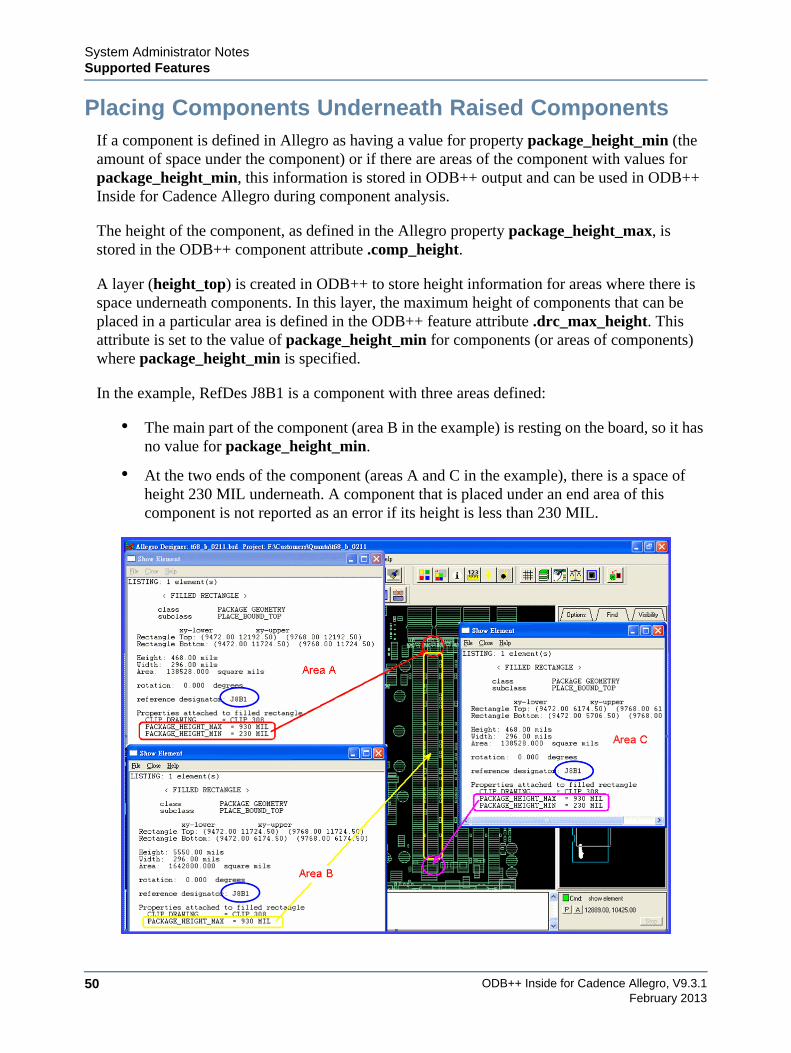
Placing Components Underneath Raised ComponentsIf a component is defined in Allegro as having a value for property package_height_min (the amount of space under the component) or if there are areas of the component with values for package_height_min, this information is stored in ODB++ output and can be used in ODB++ Inside for Cadence Allegro during component analysis.
The height of the component, as defined in the Allegro property package_height_max, is stored in the ODB++ component attribute .comp_height.
A layer (height_top) is created in ODB++ to store height information for areas where there is space underneath components. In this layer, the maximum height of components that can be placed in a particular area is defined in the ODB++ feature attribute .drc_max_height. This attribute is set to the value of package_height_min for components (or areas of components) where package_height_min is specified.
In the example, RefDes J8B1 is a component with three areas defined:
• The main part of the component (area B in the example) is resting on the board, so it has no value for package_height_min.
• At the two ends of the component (areas A and C in the example), there is a space of height 230 MIL underneath. A component that is placed under an end area of this component is not reported as an error if its height is less than 230 MIL.
System Administrator NotesSupported Features
ODB++ Inside for Cadence Allegro, V9.3.1 51February 2013
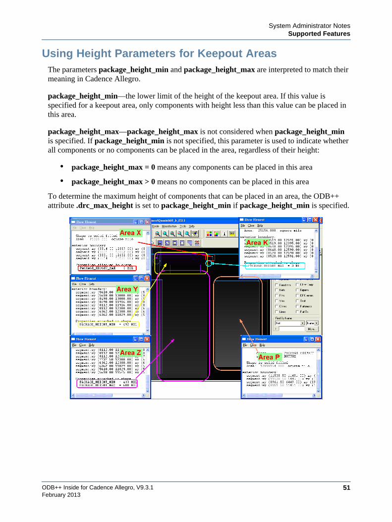
Using Height Parameters for Keepout AreasThe parameters package_height_min and package_height_max are interpreted to match their meaning in Cadence Allegro.
package_height_min—the lower limit of the height of the keepout area. If this value is specified for a keepout area, only components with height less than this value can be placed in this area.
package_height_max—package_height_max is not considered when package_height_min is specified. If package_height_min is not specified, this parameter is used to indicate whether all components or no components can be placed in the area, regardless of their height:
• package_height_max = 0 means any components can be placed in this area
• package_height_max > 0 means no components can be placed in this area
To determine the maximum height of components that can be placed in an area, the ODB++ attribute .drc_max_height is set to package_height_min if package_height_min is specified.
ODB++ Inside for Cadence Allegro, V9.3.152
System Administrator NotesSupported Features
February 2013
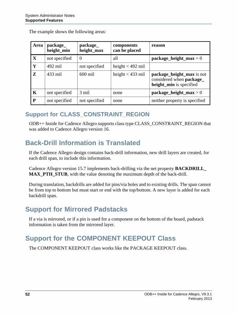
The example shows the following areas:
Support for CLASS_CONSTRAINT_REGIONODB++ Inside for Cadence Allegro supports class type CLASS_CONSTRAINT_REGION that was added to Cadence Allegro version 16.
Back-Drill Information is TranslatedIf the Cadence Allegro design contains back-drill information, new drill layers are created, for each drill span, to include this information.
Cadence Allegro version 15.7 implements back-drilling via the net property BACKDRILL_MAX_PTH_STUB, with the value denoting the maximum depth of the back-drill.
During translation, backdrills are added for pins/via holes and to existing drills. The span cannot be from top to bottom but must start or end with the top/bottom. A new layer is added for each backdrill span.
Support for Mirrored PadstacksIf a via is mirrored, or if a pin is used for a component on the bottom of the board, padstack information is taken from the mirrored layer.
Support for the COMPONENT KEEPOUT ClassThe COMPONENT KEEPOUT class works like the PACKAGE KEEPOUT class.
Area package_height_min
package_height_max
componentscan be placed
reason
X not specified 0 all package_height_max = 0
Y 492 mil not specified height < 492 mil
Z 433 mil 600 mil height < 433 mil package_height_max is not considered when package_height_min is specified
K not specified 3 mil none package_height_max > 0
P not specified not specified none neither property is specified
System Administrator NotesRelease Notes
ODB++ Inside for Cadence Allegro, V9.3.1 53February 2013
Release NotesFeatures and resolved issues are listed for these versions:
• Version 9.0 Features and Resolved Issues
• Version 9.1 Features and Resolved Issues
• Version 9.2 Features and Resolved Issues
• Version 9.3 Features and Resolved Issues
Version 9.0 Features and Resolved IssuesThese issues were resolved in this version.
ID Issue
9419 There was no way to specify that component outlines should be taken from user-defined classes. See the Component Outline parameter in “Specifying Parameters Specific to Cadence Allegro” on page 10.
14875 Translation failed if the net properties file was very large.
16797 The COMPONENT KEEPOUT class was not recognized as defining a keepout area.
16855 The dimensions of the profile were incorrect.
16878 FILLETS from Cadence Allegro V16.2 were not assigned the .tear_drop attribute during translation.
16342SF 8413, SF 8665
Features were missing when they were defined in a mirrored padstack.See “Support for Mirrored Padstacks” on page 52.
16900 - SF 8715 Translation failed during profile creation.
SF 11342 Application crashed during translation.
SF 11541 If there are components with both ASSEMBLY_TOP and ASSEMBLY_BOTTOM, or PLACE_BOUND_TOP and PLACE_BOUND_BOTTOM, how does the translator decide on the placement side?
SF 8032 Slot figures were missing from the translation.
SF 8664 If a drill is OBLONG_Y and its size in the pins file does not match its size in the padstack, the drill slot was sometimes rotated incorrectly relative to the copper layer pads.
SF 8758 ODB++ Inside for Cadence Allegro could not be run on Linux RH5.
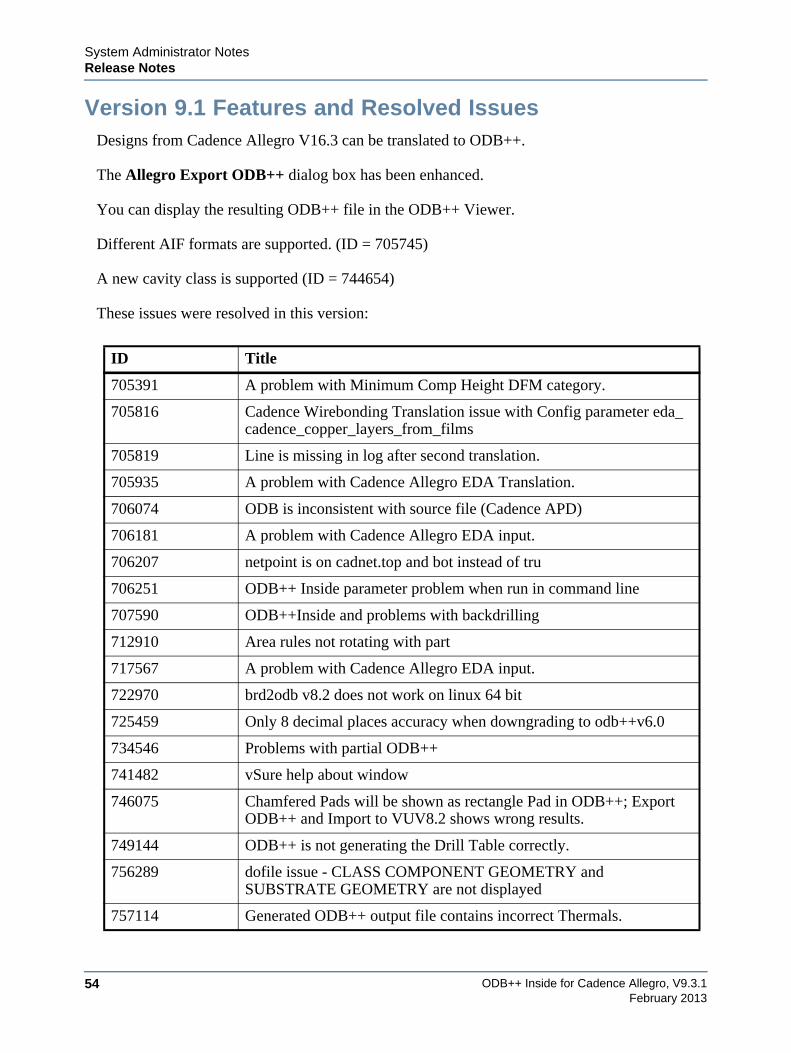
ODB++ Inside for Cadence Allegro, V9.3.154
System Administrator NotesRelease Notes
February 2013
Version 9.1 Features and Resolved IssuesDesigns from Cadence Allegro V16.3 can be translated to ODB++.
The Allegro Export ODB++ dialog box has been enhanced.
You can display the resulting ODB++ file in the ODB++ Viewer.
Different AIF formats are supported. (ID = 705745)
A new cavity class is supported (ID = 744654)
These issues were resolved in this version:
ID Title
705391 A problem with Minimum Comp Height DFM category.
705816 Cadence Wirebonding Translation issue with Config parameter eda_cadence_copper_layers_from_films
705819 Line is missing in log after second translation.
705935 A problem with Cadence Allegro EDA Translation.
706074 ODB is inconsistent with source file (Cadence APD)
706181 A problem with Cadence Allegro EDA input.
706207 netpoint is on cadnet.top and bot instead of tru
706251 ODB++ Inside parameter problem when run in command line
707590 ODB++Inside and problems with backdrilling
712910 Area rules not rotating with part
717567 A problem with Cadence Allegro EDA input.
722970 brd2odb v8.2 does not work on linux 64 bit
725459 Only 8 decimal places accuracy when downgrading to odb++v6.0
734546 Problems with partial ODB++
741482 vSure help about window
746075 Chamfered Pads will be shown as rectangle Pad in ODB++; Export ODB++ and Import to VUV8.2 shows wrong results.
749144 ODB++ is not generating the Drill Table correctly.
756289 dofile issue - CLASS COMPONENT GEOMETRY and SUBSTRATE GEOMETRY are not displayed
757114 Generated ODB++ output file contains incorrect Thermals.
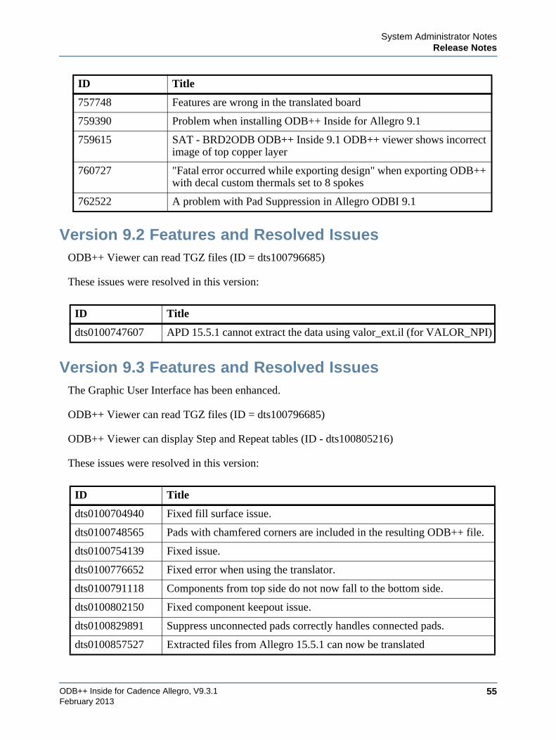
System Administrator NotesRelease Notes
ODB++ Inside for Cadence Allegro, V9.3.1 55February 2013
Version 9.2 Features and Resolved IssuesODB++ Viewer can read TGZ files (ID = dts100796685)
These issues were resolved in this version:
Version 9.3 Features and Resolved IssuesThe Graphic User Interface has been enhanced.
ODB++ Viewer can read TGZ files (ID = dts100796685)
ODB++ Viewer can display Step and Repeat tables (ID - dts100805216)
These issues were resolved in this version:
757748 Features are wrong in the translated board
759390 Problem when installing ODB++ Inside for Allegro 9.1
759615 SAT - BRD2ODB ODB++ Inside 9.1 ODB++ viewer shows incorrect image of top copper layer
760727 "Fatal error occurred while exporting design" when exporting ODB++ with decal custom thermals set to 8 spokes
762522 A problem with Pad Suppression in Allegro ODBI 9.1
ID Title
dts0100747607 APD 15.5.1 cannot extract the data using valor_ext.il (for VALOR_NPI)
ID Title
dts0100704940 Fixed fill surface issue.
dts0100748565 Pads with chamfered corners are included in the resulting ODB++ file.
dts0100754139 Fixed issue.
dts0100776652 Fixed error when using the translator.
dts0100791118 Components from top side do not now fall to the bottom side.
dts0100802150 Fixed component keepout issue.
dts0100829891 Suppress unconnected pads correctly handles connected pads.
dts0100857527 Extracted files from Allegro 15.5.1 can now be translated
ID Title
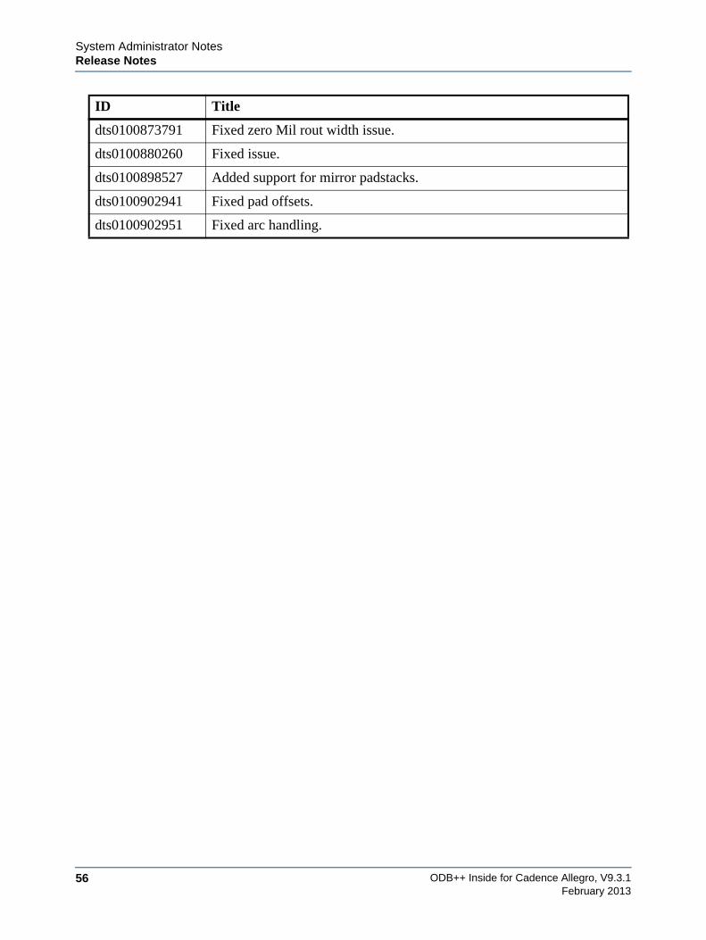
ODB++ Inside for Cadence Allegro, V9.3.156
System Administrator NotesRelease Notes
February 2013
dts0100873791 Fixed zero Mil rout width issue.
dts0100880260 Fixed issue.
dts0100898527 Added support for mirror padstacks.
dts0100902941 Fixed pad offsets.
dts0100902951 Fixed arc handling.
ID Title
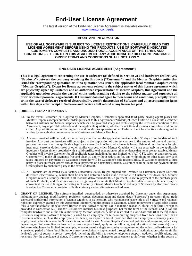
End-User License AgreementThe latest version of the End-User License Agreement is available on-line at:
www.mentor.com/eula
END-USER LICENSE AGREEMENT (“Agreement”)
This is a legal agreement concerning the use of Software (as defined in Section 2) and hardware (collectively“Products”) between the company acquiring the Products (“Customer”), and the Mentor Graphics entity thatissued the corresponding quotation or, if no quotation was issued, the applicable local Mentor Graphics entity(“Mentor Graphics”). Except for license agreements related to the subject matter of this license agreement whichare physically signed by Customer and an authorized representative of Mentor Graphics, this Agreement and theapplicable quotation contain the parties' entire understanding relating to the subject matter and supersede allprior or contemporaneous agreements. If Customer does not agree to these terms and conditions, promptly returnor, in the case of Software received electronically, certify destruction of Software and all accompanying itemswithin five days after receipt of Software and receive a full refund of any license fee paid.
1. ORDERS, FEES AND PAYMENT.
1.1. To the extent Customer (or if agreed by Mentor Graphics, Customer’s appointed third party buying agent) places andMentor Graphics accepts purchase orders pursuant to this Agreement (“Order(s)”), each Order will constitute a contractbetween Customer and Mentor Graphics, which shall be governed solely and exclusively by the terms and conditions of thisAgreement, any applicable addenda and the applicable quotation, whether or not these documents are referenced on theOrder. Any additional or conflicting terms and conditions appearing on an Order will not be effective unless agreed inwriting by an authorized representative of Customer and Mentor Graphics.
1.2. Amounts invoiced will be paid, in the currency specified on the applicable invoice, within 30 days from the date of suchinvoice. Any past due invoices will be subject to the imposition of interest charges in the amount of one and one-halfpercent per month or the applicable legal rate currently in effect, whichever is lower. Prices do not include freight,insurance, customs duties, taxes or other similar charges, which Mentor Graphics will state separately in the applicableinvoice(s). Unless timely provided with a valid certificate of exemption or other evidence that items are not taxable, MentorGraphics will invoice Customer for all applicable taxes including, but not limited to, VAT, GST, sales tax and service tax.Customer will make all payments free and clear of, and without reduction for, any withholding or other taxes; any suchtaxes imposed on payments by Customer hereunder will be Customer’s sole responsibility. If Customer appoints a thirdparty to place purchase orders and/or make payments on Customer’s behalf, Customer shall be liable for payment underOrders placed by such third party in the event of default.
1.3. All Products are delivered FCA factory (Incoterms 2000), freight prepaid and invoiced to Customer, except Softwaredelivered electronically, which shall be deemed delivered when made available to Customer for download. MentorGraphics retains a security interest in all Products delivered under this Agreement, to secure payment of the purchase priceof such Products, and Customer agrees to sign any documents that Mentor Graphics determines to be necessary orconvenient for use in filing or perfecting such security interest. Mentor Graphics’ delivery of Software by electronic meansis subject to Customer’s provision of both a primary and an alternate e-mail address.
2. GRANT OF LICENSE. The software installed, downloaded, or otherwise acquired by Customer under this Agreement,including any updates, modifications, revisions, copies, documentation and design data (“Software”) are copyrighted, tradesecret and confidential information of Mentor Graphics or its licensors, who maintain exclusive title to all Software and retain allrights not expressly granted by this Agreement. Mentor Graphics grants to Customer, subject to payment of applicable licensefees, a nontransferable, nonexclusive license to use Software solely: (a) in machine-readable, object-code form (except asprovided in Subsection 5.2); (b) for Customer’s internal business purposes; (c) for the term of the license; and (d) on thecomputer hardware and at the site authorized by Mentor Graphics. A site is restricted to a one-half mile (800 meter) radius.Customer may have Software temporarily used by an employee for telecommuting purposes from locations other than aCustomer office, such as the employee's residence, an airport or hotel, provided that such employee's primary place ofemployment is the site where the Software is authorized for use. Mentor Graphics’ standard policies and programs, which varydepending on Software, license fees paid or services purchased, apply to the following: (a) relocation of Software; (b) use ofSoftware, which may be limited, for example, to execution of a single session by a single user on the authorized hardware or fora restricted period of time (such limitations may be technically implemented through the use of authorization codes or similardevices); and (c) support services provided, including eligibility to receive telephone support, updates, modifications, andrevisions. For the avoidance of doubt, if Customer requests any change or enhancement to Software, whether in the course of
IMPORTANT INFORMATION
USE OF ALL SOFTWARE IS SUBJECT TO LICENSE RESTRICTIONS. CAREFULLY READ THIS LICENSE AGREEMENT BEFORE USING THE PRODUCTS. USE OF SOFTWARE INDICATES
CUSTOMER’S COMPLETE AND UNCONDITIONAL ACCEPTANCE OF THE TERMS AND CONDITIONS SET FORTH IN THIS AGREEMENT. ANY ADDITIONAL OR DIFFERENT PURCHASE
ORDER TERMS AND CONDITIONS SHALL NOT APPLY.
receiving support or consulting services, evaluating Software, performing beta testing or otherwise, any inventions, productimprovements, modifications or developments made by Mentor Graphics (at Mentor Graphics’ sole discretion) will be theexclusive property of Mentor Graphics.
3. ESC SOFTWARE. If Customer purchases a license to use development or prototyping tools of Mentor Graphics’ EmbeddedSoftware Channel (“ESC”), Mentor Graphics grants to Customer a nontransferable, nonexclusive license to reproduce anddistribute executable files created using ESC compilers, including the ESC run-time libraries distributed with ESC C and C++compiler Software that are linked into a composite program as an integral part of Customer’s compiled computer program,provided that Customer distributes these files only in conjunction with Customer’s compiled computer program. MentorGraphics does NOT grant Customer any right to duplicate, incorporate or embed copies of Mentor Graphics’ real-time operatingsystems or other embedded software products into Customer’s products or applications without first signing or otherwiseagreeing to a separate agreement with Mentor Graphics for such purpose.
4. BETA CODE.
4.1. Portions or all of certain Software may contain code for experimental testing and evaluation (“Beta Code”), which may notbe used without Mentor Graphics’ explicit authorization. Upon Mentor Graphics’ authorization, Mentor Graphics grants toCustomer a temporary, nontransferable, nonexclusive license for experimental use to test and evaluate the Beta Codewithout charge for a limited period of time specified by Mentor Graphics. This grant and Customer’s use of the Beta Codeshall not be construed as marketing or offering to sell a license to the Beta Code, which Mentor Graphics may choose not torelease commercially in any form.
4.2. If Mentor Graphics authorizes Customer to use the Beta Code, Customer agrees to evaluate and test the Beta Code undernormal conditions as directed by Mentor Graphics. Customer will contact Mentor Graphics periodically during Customer’suse of the Beta Code to discuss any malfunctions or suggested improvements. Upon completion of Customer’s evaluationand testing, Customer will send to Mentor Graphics a written evaluation of the Beta Code, including its strengths,weaknesses and recommended improvements.
4.3. Customer agrees to maintain Beta Code in confidence and shall restrict access to the Beta Code, including the methods andconcepts utilized therein, solely to those employees and Customer location(s) authorized by Mentor Graphics to performbeta testing. Customer agrees that any written evaluations and all inventions, product improvements, modifications ordevelopments that Mentor Graphics conceived or made during or subsequent to this Agreement, including those basedpartly or wholly on Customer’s feedback, will be the exclusive property of Mentor Graphics. Mentor Graphics will haveexclusive rights, title and interest in all such property. The provisions of this Subsection 4.3 shall survive termination of thisAgreement.
5. RESTRICTIONS ON USE.
5.1. Customer may copy Software only as reasonably necessary to support the authorized use. Each copy must include allnotices and legends embedded in Software and affixed to its medium and container as received from Mentor Graphics. Allcopies shall remain the property of Mentor Graphics or its licensors. Customer shall maintain a record of the number andprimary location of all copies of Software, including copies merged with other software, and shall make those recordsavailable to Mentor Graphics upon request. Customer shall not make Products available in any form to any person otherthan Customer’s employees and on-site contractors, excluding Mentor Graphics competitors, whose job performancerequires access and who are under obligations of confidentiality. Customer shall take appropriate action to protect theconfidentiality of Products and ensure that any person permitted access does not disclose or use it except as permitted bythis Agreement. Customer shall give Mentor Graphics written notice of any unauthorized disclosure or use of the Productsas soon as Customer learns or becomes aware of such unauthorized disclosure or use. Except as otherwise permitted forpurposes of interoperability as specified by applicable and mandatory local law, Customer shall not reverse-assemble,reverse-compile, reverse-engineer or in any way derive any source code from Software. Log files, data files, rule files andscript files generated by or for the Software (collectively “Files”), including without limitation files containing StandardVerification Rule Format (“SVRF”) and Tcl Verification Format (“TVF”) which are Mentor Graphics’ proprietary syntaxesfor expressing process rules, constitute or include confidential information of Mentor Graphics. Customer may share Fileswith third parties, excluding Mentor Graphics competitors, provided that the confidentiality of such Files is protected bywritten agreement at least as well as Customer protects other information of a similar nature or importance, but in any casewith at least reasonable care. Customer may use Files containing SVRF or TVF only with Mentor Graphics products. Underno circumstances shall Customer use Software or Files or allow their use for the purpose of developing, enhancing ormarketing any product that is in any way competitive with Software, or disclose to any third party the results of, orinformation pertaining to, any benchmark.
5.2. If any Software or portions thereof are provided in source code form, Customer will use the source code only to correctsoftware errors and enhance or modify the Software for the authorized use. Customer shall not disclose or permit disclosureof source code, in whole or in part, including any of its methods or concepts, to anyone except Customer’s employees orcontractors, excluding Mentor Graphics competitors, with a need to know. Customer shall not copy or compile source codein any manner except to support this authorized use.
5.3. Customer may not assign this Agreement or the rights and duties under it, or relocate, sublicense or otherwise transfer theProducts, whether by operation of law or otherwise (“Attempted Transfer”), without Mentor Graphics’ prior written consentand payment of Mentor Graphics’ then-current applicable relocation and/or transfer fees. Any Attempted Transfer withoutMentor Graphics’ prior written consent shall be a material breach of this Agreement and may, at Mentor Graphics’ option,result in the immediate termination of the Agreement and/or the licenses granted under this Agreement. The terms of this
Agreement, including without limitation the licensing and assignment provisions, shall be binding upon Customer’spermitted successors in interest and assigns.
5.4. The provisions of this Section 5 shall survive the termination of this Agreement.
6. SUPPORT SERVICES. To the extent Customer purchases support services, Mentor Graphics will provide Customer updatesand technical support for the Products, at the Customer site(s) for which support is purchased, in accordance with MentorGraphics’ then current End-User Support Terms located at http://supportnet.mentor.com/about/legal/.
7. AUTOMATIC CHECK FOR UPDATES; PRIVACY. Technological measures in Software may communicate with serversof Mentor Graphics or its contractors for the purpose of checking for and notifying the user of updates and to ensure that theSoftware in use is licensed in compliance with this Agreement. Mentor Graphics will not collect any personally identifiable datain this process and will not disclose any data collected to any third party without the prior written consent of Customer, except toMentor Graphics’ outside attorneys or as may be required by a court of competent jurisdiction.
8. LIMITED WARRANTY.
8.1. Mentor Graphics warrants that during the warranty period its standard, generally supported Products, when properlyinstalled, will substantially conform to the functional specifications set forth in the applicable user manual. MentorGraphics does not warrant that Products will meet Customer’s requirements or that operation of Products will beuninterrupted or error free. The warranty period is 90 days starting on the 15th day after delivery or upon installation,whichever first occurs. Customer must notify Mentor Graphics in writing of any nonconformity within the warranty period.For the avoidance of doubt, this warranty applies only to the initial shipment of Software under an Order and does notrenew or reset, for example, with the delivery of (a) Software updates or (b) authorization codes or alternate Software undera transaction involving Software re-mix. This warranty shall not be valid if Products have been subject to misuse,unauthorized modification or improper installation. MENTOR GRAPHICS’ ENTIRE LIABILITY AND CUSTOMER’SEXCLUSIVE REMEDY SHALL BE, AT MENTOR GRAPHICS’ OPTION, EITHER (A) REFUND OF THE PRICEPAID UPON RETURN OF THE PRODUCTS TO MENTOR GRAPHICS OR (B) MODIFICATION ORREPLACEMENT OF THE PRODUCTS THAT DO NOT MEET THIS LIMITED WARRANTY, PROVIDEDCUSTOMER HAS OTHERWISE COMPLIED WITH THIS AGREEMENT. MENTOR GRAPHICS MAKES NOWARRANTIES WITH RESPECT TO: (A) SERVICES; (B) PRODUCTS PROVIDED AT NO CHARGE; OR (C) BETACODE; ALL OF WHICH ARE PROVIDED “AS IS.”
8.2. THE WARRANTIES SET FORTH IN THIS SECTION 8 ARE EXCLUSIVE. NEITHER MENTOR GRAPHICS NORITS LICENSORS MAKE ANY OTHER WARRANTIES EXPRESS, IMPLIED OR STATUTORY, WITH RESPECT TOPRODUCTS PROVIDED UNDER THIS AGREEMENT. MENTOR GRAPHICS AND ITS LICENSORSSPECIFICALLY DISCLAIM ALL IMPLIED WARRANTIES OF MERCHANTABILITY, FITNESS FOR APARTICULAR PURPOSE AND NON-INFRINGEMENT OF INTELLECTUAL PROPERTY.
9. LIMITATION OF LIABILITY. EXCEPT WHERE THIS EXCLUSION OR RESTRICTION OF LIABILITY WOULD BEVOID OR INEFFECTIVE UNDER APPLICABLE LAW, IN NO EVENT SHALL MENTOR GRAPHICS OR ITSLICENSORS BE LIABLE FOR INDIRECT, SPECIAL, INCIDENTAL, OR CONSEQUENTIAL DAMAGES (INCLUDINGLOST PROFITS OR SAVINGS) WHETHER BASED ON CONTRACT, TORT OR ANY OTHER LEGAL THEORY, EVENIF MENTOR GRAPHICS OR ITS LICENSORS HAVE BEEN ADVISED OF THE POSSIBILITY OF SUCH DAMAGES. INNO EVENT SHALL MENTOR GRAPHICS’ OR ITS LICENSORS’ LIABILITY UNDER THIS AGREEMENT EXCEEDTHE AMOUNT RECEIVED FROM CUSTOMER FOR THE HARDWARE, SOFTWARE LICENSE OR SERVICE GIVINGRISE TO THE CLAIM. IN THE CASE WHERE NO AMOUNT WAS PAID, MENTOR GRAPHICS AND ITS LICENSORSSHALL HAVE NO LIABILITY FOR ANY DAMAGES WHATSOEVER. THE PROVISIONS OF THIS SECTION 9 SHALLSURVIVE THE TERMINATION OF THIS AGREEMENT.
10. HAZARDOUS APPLICATIONS. CUSTOMER ACKNOWLEDGES IT IS SOLELY RESPONSIBLE FOR TESTING ITSPRODUCTS USED IN APPLICATIONS WHERE THE FAILURE OR INACCURACY OF ITS PRODUCTS MIGHTRESULT IN DEATH OR PERSONAL INJURY (“HAZARDOUS APPLICATIONS”). NEITHER MENTOR GRAPHICSNOR ITS LICENSORS SHALL BE LIABLE FOR ANY DAMAGES RESULTING FROM OR IN CONNECTION WITHTHE USE OF MENTOR GRAPHICS PRODUCTS IN OR FOR HAZARDOUS APPLICATIONS. THE PROVISIONS OFTHIS SECTION 10 SHALL SURVIVE THE TERMINATION OF THIS AGREEMENT.
11. INDEMNIFICATION. CUSTOMER AGREES TO INDEMNIFY AND HOLD HARMLESS MENTOR GRAPHICS ANDITS LICENSORS FROM ANY CLAIMS, LOSS, COST, DAMAGE, EXPENSE OR LIABILITY, INCLUDINGATTORNEYS’ FEES, ARISING OUT OF OR IN CONNECTION WITH THE USE OF PRODUCTS AS DESCRIBED INSECTION 10. THE PROVISIONS OF THIS SECTION 11 SHALL SURVIVE THE TERMINATION OF THISAGREEMENT.
12. INFRINGEMENT.
12.1. Mentor Graphics will defend or settle, at its option and expense, any action brought against Customer in the United States,Canada, Japan, or member state of the European Union which alleges that any standard, generally supported Productacquired by Customer hereunder infringes a patent or copyright or misappropriates a trade secret in such jurisdiction.Mentor Graphics will pay costs and damages finally awarded against Customer that are attributable to the action. Customerunderstands and agrees that as conditions to Mentor Graphics’ obligations under this section Customer must: (a) notifyMentor Graphics promptly in writing of the action; (b) provide Mentor Graphics all reasonable information and assistance
to settle or defend the action; and (c) grant Mentor Graphics sole authority and control of the defense or settlement of theaction.
12.2. If a claim is made under Subsection 12.1 Mentor Graphics may, at its option and expense, (a) replace or modify the Productso that it becomes noninfringing; (b) procure for Customer the right to continue using the Product; or (c) require the returnof the Product and refund to Customer any purchase price or license fee paid, less a reasonable allowance for use.
12.3. Mentor Graphics has no liability to Customer if the action is based upon: (a) the combination of Software or hardware withany product not furnished by Mentor Graphics; (b) the modification of the Product other than by Mentor Graphics; (c) theuse of other than a current unaltered release of Software; (d) the use of the Product as part of an infringing process; (e) aproduct that Customer makes, uses, or sells; (f) any Beta Code or Product provided at no charge; (g) any software providedby Mentor Graphics’ licensors who do not provide such indemnification to Mentor Graphics’ customers; or(h) infringement by Customer that is deemed willful. In the case of (h), Customer shall reimburse Mentor Graphics for itsreasonable attorney fees and other costs related to the action.
12.4. THIS SECTION 12 IS SUBJECT TO SECTION 9 ABOVE AND STATES THE ENTIRE LIABILITY OF MENTORGRAPHICS AND ITS LICENSORS FOR DEFENSE, SETTLEMENT AND DAMAGES, AND CUSTOMER’S SOLEAND EXCLUSIVE REMEDY, WITH RESPECT TO ANY ALLEGED PATENT OR COPYRIGHT INFRINGEMENTOR TRADE SECRET MISAPPROPRIATION BY ANY PRODUCT PROVIDED UNDER THIS AGREEMENT.
13. TERMINATION AND EFFECT OF TERMINATION. If a Software license was provided for limited term use, such licensewill automatically terminate at the end of the authorized term.
13.1. Mentor Graphics may terminate this Agreement and/or any license granted under this Agreement immediately upon writtennotice if Customer: (a) exceeds the scope of the license or otherwise fails to comply with the licensing or confidentialityprovisions of this Agreement, or (b) becomes insolvent, files a bankruptcy petition, institutes proceedings for liquidation orwinding up or enters into an agreement to assign its assets for the benefit of creditors. For any other material breach of anyprovision of this Agreement, Mentor Graphics may terminate this Agreement and/or any license granted under thisAgreement upon 30 days written notice if Customer fails to cure the breach within the 30 day notice period. Termination ofthis Agreement or any license granted hereunder will not affect Customer’s obligation to pay for Products shipped orlicenses granted prior to the termination, which amounts shall be payable immediately upon the date of termination.
13.2. Upon termination of this Agreement, the rights and obligations of the parties shall cease except as expressly set forth in thisAgreement. Upon termination, Customer shall ensure that all use of the affected Products ceases, and shall return hardwareand either return to Mentor Graphics or destroy Software in Customer’s possession, including all copies anddocumentation, and certify in writing to Mentor Graphics within ten business days of the termination date that Customer nolonger possesses any of the affected Products or copies of Software in any form.
14. EXPORT. The Products provided hereunder are subject to regulation by local laws and United States government agencies,which prohibit export or diversion of certain products and information about the products to certain countries and certainpersons. Customer agrees that it will not export Products in any manner without first obtaining all necessary approval fromappropriate local and United States government agencies.
15. U.S. GOVERNMENT LICENSE RIGHTS. Software was developed entirely at private expense. All Software is commercialcomputer software within the meaning of the applicable acquisition regulations. Accordingly, pursuant to US FAR 48 CFR12.212 and DFAR 48 CFR 227.7202, use, duplication and disclosure of the Software by or for the U.S. Government or a U.S.Government subcontractor is subject solely to the terms and conditions set forth in this Agreement, except for provisions whichare contrary to applicable mandatory federal laws.
16. THIRD PARTY BENEFICIARY. Mentor Graphics Corporation, Mentor Graphics (Ireland) Limited, Microsoft Corporationand other licensors may be third party beneficiaries of this Agreement with the right to enforce the obligations set forth herein.
17. REVIEW OF LICENSE USAGE. Customer will monitor the access to and use of Software. With prior written notice andduring Customer’s normal business hours, Mentor Graphics may engage an internationally recognized accounting firm to reviewCustomer’s software monitoring system and records deemed relevant by the internationally recognized accounting firm toconfirm Customer’s compliance with the terms of this Agreement or U.S. or other local export laws. Such review may includeFLEXlm or FLEXnet (or successor product) report log files that Customer shall capture and provide at Mentor Graphics’request. Customer shall make records available in electronic format and shall fully cooperate with data gathering to support thelicense review. Mentor Graphics shall bear the expense of any such review unless a material non-compliance is revealed. MentorGraphics shall treat as confidential information all information gained as a result of any request or review and shall only use ordisclose such information as required by law or to enforce its rights under this Agreement. The provisions of this Section 17shall survive the termination of this Agreement.
18. CONTROLLING LAW, JURISDICTION AND DISPUTE RESOLUTION. The owners of certain Mentor Graphicsintellectual property licensed under this Agreement are located in Ireland and the United States. To promote consistency aroundthe world, disputes shall be resolved as follows: excluding conflict of laws rules, this Agreement shall be governed by andconstrued under the laws of the State of Oregon, USA, if Customer is located in North or South America, and the laws of Irelandif Customer is located outside of North or South America. All disputes arising out of or in relation to this Agreement shall besubmitted to the exclusive jurisdiction of the courts of Portland, Oregon when the laws of Oregon apply, or Dublin, Ireland whenthe laws of Ireland apply. Notwithstanding the foregoing, all disputes in Asia arising out of or in relation to this Agreement shallbe resolved by arbitration in Singapore before a single arbitrator to be appointed by the chairman of the Singapore International
Arbitration Centre (“SIAC”) to be conducted in the English language, in accordance with the Arbitration Rules of the SIAC ineffect at the time of the dispute, which rules are deemed to be incorporated by reference in this section. This section shall notrestrict Mentor Graphics’ right to bring an action against Customer in the jurisdiction where Customer’s place of business islocated. The United Nations Convention on Contracts for the International Sale of Goods does not apply to this Agreement.
19. SEVERABILITY. If any provision of this Agreement is held by a court of competent jurisdiction to be void, invalid,unenforceable or illegal, such provision shall be severed from this Agreement and the remaining provisions will remain in fullforce and effect.
20. MISCELLANEOUS. This Agreement contains the parties’ entire understanding relating to its subject matter and supersedes allprior or contemporaneous agreements, including but not limited to any purchase order terms and conditions. Some Softwaremay contain code distributed under a third party license agreement that may provide additional rights to Customer. Please seethe applicable Software documentation for details. This Agreement may only be modified in writing by authorizedrepresentatives of the parties. Waiver of terms or excuse of breach must be in writing and shall not constitute subsequentconsent, waiver or excuse.
Rev. 100615, Part No. 246066