Embed Size (px)
Citation preview

VALUE YELLOW PAGES SYSTEM
A Group Project for COMP 6471 – Software Design Methodologies
Done by
Tahira Hasan 6198856 Meenakshi Venkat 4531159
Rajbir Kaur 6004628 Tanvir Khan 6019285 Yulong Chen 5795281
Submitted on July 27th, 2007

TABLE OF CONTENTS
1 Vision Document..........................................................................................................................5
2 Software Requirement Specification..............................................................................13
3 Software Architecture Document.....................................................................................38
Glossary ....................................................................................................................................................61
References ..............................................................................................................................................63
2

Vision Document
For Value YPS
3

VALUE YPS VISION DOCUMENT
TABLE OF CONTENTS
Introduction ..............................................................................................................................................5
1.1 Positioning ..................................................................................................................................5
1.1.1 Problem Statement .....................................................................................................5
1.1.2 Product Position Statement...................................................................................5
1.2 Stakeholder and User Descriptions ...............................................................................6
1.2.1 Stakeholder Summary ...............................................................................................6
1.2.2 User Summary ...............................................................................................................6
1.3 Product Overview ....................................................................................................................7
1.3.1 Product Perspective...................................................................................................7
1.3.2 Assumptions And Dependencies .........................................................................8
1.3.3 Needs And Features ...................................................................................................8
4

VALUE YPS VISION DOCUMENT
Vision Document
Introduction We envision a state-of-the-art online directory of Yellow Pages, Value Yellow Pages
System (YPS), which provides its consumers with quick access to information on
virtually every business entity through integration with multiple third-party supporting
systems.
1.1 Positioning
1.1.1 Problem Statement
The problem of online Yellow Pages directories being out-of-date, providing vague information and difficult to use.
Affects Searchers, Businesses and Corporate Management The impact of which is
misleading or incomplete search results. This leads to a drop in the use of Yellow Pages and a subsequent drop in the sales of business entities.
A successful solution would be
a web application that helps millions of searchers in finding up-to-date business information and a process whereby only the concerned parties can update their entries
1.1.2 Product Position Statement
For • Searchers • Businesses
Who • want to find information and profiles of businesses • want to advertise their businesses
The Value YPS will be an enterprise application That will provide easy search, reliable results and effective
advertising opportunities Our product will have attractive, user friendly and secure interfaces,
advanced search option, dynamic maps, and the most extensive, complete and current information on small, medium and large business organizations.
5

VALUE YPS VISION DOCUMENT
1.2 Stakeholder and User Descriptions
1.2.1 Stakeholder Summary
Name Description Responsibilities Administrators ValueYPS employee Monitors the system to ensure proper
operation Developer ValueYPS employee Builds/maintains the system Value Group Owners of the
Application Provides resources, and handles legal issues
Google Inc. Search Engine Provides maps and driving directions
Government Business Registration system (GBRS)
Business regulatory body which maintains information of all running businesses
Data Provider; Provides current information of businesses listed
Payment System
Online payment method
Accepts payment of businesses which want to advertise at Value YPS. Sends payment records to Manager. Transfers payment to Value YPS's account.
1.2.2 User Summary
Name Description Responsibilities Searcher Consumer of the
information. Searches for the Business Listings, Maps and Driving Directions
Manager YP employee • Creates, deletes and updates business listings
• Processes the enhancement requests of the business representatives
Business Representative (BR)
Employee of the business listed in ValueYPS
Requests for enhanced business listings
6

VALUE YPS SOFTWARE REQUIREMENT DOCUMENT
1.3 Product Overview Value YPS will be the business information expert, a top online resource for finding
information and contact details of businesses. It will provide a basic business listing for
every business that registers with the GBRS. It will also allow its users to access maps
and directions for the search results through the use of Google Maps. The use of reliable
third party systems is to ensure consistency of information at Value YPS. It also provides
Value YPS a competitive edge over the other systems that allow business organizations
to list themselves, which results in not only incomplete information but also a risk of
erroneous or false information. However, Paid enhancements service would be available,
which can be requested by a BR. These enhancements can include additional details
about their business such as hours of operation, accepted payment methods, a link to a
company web site, display company logo and other information that is valuable to the
user. This information will be evaluated by the Manager to ensure it correct and conforms
to the standards of Value YPS. The searchers will be able to search for business listings
in an interactive environment where the user interface will provide them with search tips
and help them refine their search criteria. The system will provide each user with
multiple search results that best match the search criteria.
1.3.1 Product Perspective
Figure 1.1 Value YPS context Diagram
7

VALUE YPS SOFTWARE REQUIREMENT DOCUMENT
1.3.2 Assumptions and Dependencies
Need Priority Features
M Provides Searching Tips
H Retrieves multiple search results that match whole/part
of search criteria
L Provides Driving Directions and Maps
Search
Business
Listings
L Supports advanced search options
H Verifies the identity of the BR Advertise
Business H Secure payment Mechanisms
H Regular updates of the business listings
M Business Listing enhancements conform to Value YPS
Policies
Manage
Business
Listings
H Regularly backup Business Listing data
1.3.3 Needs and Features
Assumptions Dependencies
Concurrent search requests Value YPS will deploy capacity web
server
Huge memory capacity Value YPS will deploy high capacity
Database Server
Accurate and up-to-date business
information
Value YPS will have access to GBRS
Users are not skilled • User-friendly interface
• Online searching tips will be provided
Maps and Driving Directions are
provided to searchers.
Value YPS will have access to Google
Maps
Business Representatives can enhance
their listings
Their business should be listed in Value
YPS
8

VALUE YPS SOFTWARE REQUIREMENT DOCUMENT
Software Requirement
Document
For Value YPS
9

VALUE YPS SOFTWARE REQUIREMENT DOCUMENT
TABLE OF CONTENTS
Introduction ........................................................................................................................................... 13
2.1 Goals And Objectives ......................................................................................................... 13
2.2 Usage Scenarios ................................................................................................................... 13
2.2.1 User Profiles................................................................................................................ 13
2.2.2 Use Case Model......................................................................................................... 14
2.2.3 System Sequence Diagrams ............................................................................... 18
2.3 Domain Model And Description ..................................................................................... 21
2.3.1 Businesslisting........................................................................................................... 21
2.3.2 Catagory ........................................................................................................................ 21
2.3.3 Enhancementrequest ............................................................................................. 21
2.4 Supplementary Specifications ...................................................................................... 23
2.4.1Usability.......................................................................................................................... 23
2.4.1.1 Understandability........................................................................................ 23
2.4.1.2 Time For Specific Tasks.......................................................................... 23
2.4.1.3 Multilingual Interface................................................................................ 23
2.4.1.4 Input Forms .................................................................................................... 23
2.4.2 Reliability ...................................................................................................................... 24
2.4.2.1 Availability ...................................................................................................... 24
2.4.2.2 Mean-Time-To-Repair ................................................................................ 24
2.4.2.3 Back-Up Storage.......................................................................................... 24
2.4.2.4 System Administration ............................................................................. 24
2.4.3 Performance ................................................................................................................ 24
2.4.3.1 Number Of Maximum Users At The Same Time.......................... 24
2.4.3.2 Database Response Time ....................................................................... 24
2.4.4 Functionality ............................................................................................................... 25
2.4.4.1 Authentication .............................................................................................. 25
2.4.4.2 Security ............................................................................................................ 25
2.4.4.3 List Of Updates............................................................................................. 25
2.4.4.4 Privileges Of The Manager ..................................................................... 25
2.4.4.5 Printing ............................................................................................................. 25
10

VALUE YPS SOFTWARE REQUIREMENT DOCUMENT
2.4.5 Implementation Constraints ............................................................................... 26
2.4.6 User Interface ............................................................................................................ 26
2.4.6.1 Searcher Interface ..................................................................................... 26
2.4.6.2 Business Representative Interface ................................................... 30
2.4.6.3 Manager Interface ...................................................................................... 32
11

VALUE YPS SOFTWARE REQUIREMENT DOCUMENT
LIST OF FIGURES
Figure 2.1 High level Use Case Diagram 14
Figure: 2.2 Detailed USE CASE Diagram 18
Figure 2.3 SSD for Searcher Scenario 19
Figure 2.4 SSD for Manager Scenario 20
Figure 2.5 SSD for Make Request Scenario 20
Figure 2.6 Domain Model for Value YPS 22
Figure 2.7 Home page of Value YPS 27
Figure 2.8 Interface displaying results based on search criteria 28
Figure 2.9 Interface showing location map & departure address form 29
Figure 2.10 Interface showing driving directions 30
Figure 2.11 Screen shot of BR’s enhancement request page 31
Figure 2.12 Manager’s main interface 32
Figure 2.13 Interface showing the updates made to the systems 33
Figure 2.14 Interface showing the enhancement requests 34
12

VALUE YPS SOFTWARE REQUIREMENT DOCUMENT
Software Requirements Document
Introduction The subsequent sections describe all data, functional and behavioral requirements for
Value YPS. The requirements have been gathered through brainstorming sessions of
developers, stakeholder meetings and user interviews.
2.1 Goals and Objectives The main purpose of Value YPS is to provide an online Yellow Pages directory which
gives its users with up-to-date and ‘more than the typical phone directory type’ results. The goals of Value YPS are:
To have up-to-date and complete set of information on Businesses
Provide enhanced business listings offering more useful information such as business
descriptions and business hours, email addresses, maps and directions, and links to
business web sites.
Provide the general public a convenient access to the information about businesses, as
compared to conventional Yellow Pages directories.
2.2 Usage Scenarios
2.2.1 User Profiles
There will be four levels of users:
Full Control (Administrator)
Read/Write/Modify All (Manager)
Read/Write/Modify Own (BR)
Read Only (General Public (Searcher))
13

VALUE YPS SOFTWARE REQUIREMENT DOCUMENT
2.2.2 Use Case Model
Business Representative
Manager
Value YPS
Searches for
Make Request
Manages
SearcherGoogle
Payment System
GBRS
Figure 2.1 High level Use Case Diagram
USE CASE: Search for Business Listing
Primary Actor: Searcher
Goal: Searcher searches for a specific business listing
Level: User-level
Pre-condition: The website is up and running
Main Success Scenario:
1. Searcher opens the website
2. System displays search criteria input form
3. Searcher inputs the search criteria
4. System displays all the Business Listings matching the Searcher's criteria
5. Searcher leaves with the desired address
6. Use case ends successfully
14

VALUE YPS SOFTWARE REQUIREMENT DOCUMENT
Extensions(or Alternative Flows):
*a. At any time, Searcher indicates that he/she wishes to conduct another search
1. Use case resumes at step 2
3(a) Searcher missed a mandatory field or entered incorrect data type
1. System displays error message
2. Use case resumes at step 2
4(a) Searcher selects maps and directions for a displayed result
1. System interacts with the Google map to get map information.
2. System displays the maps and input form asking for the departure address
3. Searchers enters the departure address
3(a) Departure address is not found
1. The system asks for the departure address again
2. Use case resumes at step 3(a).2
3(b) System displays the driving directions
1. Use case resumes at step 5
4(b) The desired address is not found in the system’s database
1. System displays that result is not found
2. Use case ends unsuccessfully
USE CASE: Manage Business Listing
Primary Actor: Manager
Goal: Manager ensures the business listings are up-to-date
Level: User-level
Pre condition: Manager is logged in the Value YPS
Main Success Scenario:
1. Manager chooses to update the Business Listings
2. System connects to the GBRS and retrieves the log file since the last update.
3. System creates, modifies and deletes the business listings based on the retrieved
records
4. System sends the confirmation to the manager
15

VALUE YPS SOFTWARE REQUIREMENT DOCUMENT
5. System saves the current date for the last update.
6. Manager chooses to process requests
7. System displays the list of pending requests
8. Manager processes a request
9. Manager does one of the following:
9.1 Sends confirmation to the business representative
9.1.1 Manager accepts Payment
9.1.2 Manager updates the Business Listing
OR
9.2 Sends a refusal to the business representative
Manager repeats step 8-9 until all the requests have been processed
10. Use case ends successfully
Extensions(or Alternative Flows):
2(a) System cannot connect to the GBRS
1. System reports error to manager
2. Use case resumes at step 6
5(a) No requests are displayed by the system:
1. Use case continues at step 10
7(a) Manager cannot contact the business representative
1. Manager puts the request in a pending list
2. Use case continues at step 8
USE CASE: Make Request
Primary Actor: Business representative
Goal: Business representative requests for additional information to be listed with
his/her business listing
Level: User-level
Pre-condition: The BR is logged in
16

VALUE YPS SOFTWARE REQUIREMENT DOCUMENT
Main Success Scenario:
1. BR chooses the enhancement request option from the webpage.
2. System displays the enhancement request form.
3. BR fills up the form.
4. BR submits the form.
5. System directs BR to the Payment System Website.
6. BR fills the payment form
7. System receives a confirmation from the Payment System
8. System confirms the request submission to the BR
9. Use case ends successfully.
Extensions(or Alternative Flows):
*a. At any time, representative wishes to abort the request
1. Use case ends unsuccessfully.
*b. Connection lost
1. Use case ends unsuccessfully.
4(a) Invalid business Id (not in the database)
1. System signals error and rejects the request.
2. Use case resumes at step 2.
8(a) Invalid payment information
1. System signals error and rejects the request.
2. Use case resumes at step 2.
A more elaborative Use Case Diagram is shown in Figure 2.2 on next page. It shows the
<<extends>> and <<uses>> associations among the use cases.
17

VALUE YPS SOFTWARE REQUIREMENT DOCUMENT
Figure: 2.2 Detailed USE CASE Diagram
2.2.3 System Sequence Diagrams
The diagrams in this section show the input and output events related to Value YPS. An
SSD is made for each of the use cases discussed in the previous section.
18

VALUE YPS SOFTWARE REQUIREMENT DOCUMENT
USE CASE: Searches For
: Searcher : SearcherValue YPSValue YPS
1: makesearchrequest(n,l)
2: entercriteria(n,l)
3: searchresults
4: getmap
5: Showmap
6: getdrivingdirection(departure,destination)
7: displaydirection
Figure 2.3 SSD for Searcher Scenario
19

VALUE YPS SOFTWARE REQUIREMENT DOCUMENT
USE CASE: Manages Business Listings
: Manager : Manager
: Value YPS: Value YPS
1: logIn(name,password)
2: New, Updated, Deleted Business Listings
3: updateBussLis()
4: getRequests()
5: enhancement request
6: changeReqStatus(status)
loop [more requests]
Figure 2.4 SSD for Manager Scenario
USE CASE: Makes Request
: BusinessRep : BusinessRep
: Value YPS: Value YPS
1: Logs in
2: Request Form
3: Send Request
4: Confirm Request Submission
Figure 2.5 SSD for Make Request Scenario
20

VALUE YPS SOFTWARE REQUIREMENT DOCUMENT
21
4. Date: It is the date on which the request is submitted.
3. Details: It is the additional information that needs to be added in the listing. It could
include website address, email address, business overview, etc.
2. Status: It is a character to indicate the status of the request, like S for submited, P for
pending, F for finalized.
1. TrackingNumber: It is a serial number generated by system to identify each
enhancement request
2.3.3 EnhancementRequest
2. CName: It is a short description of the business type
1. CID: It is a number uniquely identify an business type description
2.3.2 Catagory
5. BusinessCategory: It contains category ID as foreign key which identify the business
type like hotel, restaurant etc.
4. BusinessLocation: It is the full business address which contains premise, street
number and name, city, region, country, and zip-code.
3. BusinessPhone: It is the business phone number which contain country code, area
code, phone number and extension
2. BusinessName: It is the full official name of the business registered with GBRS
1. BusinessId: It is the unique identity number for every registered business unit. It is
used to associate records in Value YPS and GBRS
2.3.1 BusinessListing
The Domain Model is shown in Figure 2.6. The significant conceptual classes are
described below:
2.3 Domain Model and Description

VALUE YPS SOFTWARE REQUIREMENT DOCUMENT
22
Figure 2.6 Domain Model for Value YPS

VALUE YPS SOFTWARE REQUIREMENT DOCUMENT
2.4 Supplementary Specifications The purpose of the subsequent sections is to capture non-functional requirements of the
systems which are not mentioned in the use-case models.
2.4.1 Usability
2.4.1.1 Understandability
General users should be able to use the YPS without any formal training/briefing
There should be help links to make the users familiar with the working
2.4.1.2 Time for specific tasks
The business representative’s enhancement request will not be processed at the time of
recording. He/She will receive a confirmation at a later date through email once the
request is processed by the manager at Value YPS.
2.4.1.3 Multilingual interface
The user interface has the option to select English or French and service is provided
in both the languages
The driving directions and payment will be provided only in English since they are
available through external systems.
2.4.1.4 Input forms
The input forms will be a combination of text-boxes, drop-down menus, check-boxes
and radio-buttons
The mandatory fields of the form will be marked with a star
The expiry date of the credit card should have drop-down calendars with it to avoid
confusion between (m/d/y) and (d/m/y) formats
There should be a message for the business representative if enhancement request is
accepted/rejected upon submission of the details
‘Submit’ and ‘Clear’ – these two buttons should be placed on the opposite sides of the
input page so that the user doesn’t click on the wrong button unmindfully
User should not be required to fill an entire form again if he/she makes a mistake in a
few fields; only the missed/incorrect fields should need to be entered.
Text boxes should have hints indicating how to fill them.
23

VALUE YPS SOFTWARE REQUIREMENT DOCUMENT
2.4.2 Reliability
2.4.2.1 Availability
Value YPS should be available 24/7. It should have a minimum of 95% uptime
during the whole year (measured on the percentage of total hours of the whole year);
the 5% slack being kept for maintenance issues.
All the maintenance works should be schedules after the week-days midnights. It
should strictly avoid weekend nights because it’s expected that more users are
looking for listings and directions during the holidays
If the maintenance crew know beforehand that a maintenance-work needs to be
scheduled, they should include a message at the front page that YPS site will go for
maintenance for (x-y) hours and will be down for that period
2.4.2.2 Mean-Time-To-Repair
If YPS fails unexpectedly, it should be fixed within 5 business hours.
2.4.2.3 Back-up storage
The YPS system should have backup of the data to recover it later following a
hardware/software disaster.
It will have weekly, monthly and yearly backup data storage. Every week the data
should go to monthly backup and monthly backup should go to yearly backup.
2.4.2.4 System Administration
Value YPS should have a system administrator who is responsible for configuring and
administering the infrastructure. A system administrator is also responsible for
overseeing the runtime well-being of the deployed applications.
2.4.3 Performance
2.4.3.1 Number of Maximum Users at the Same Time
YPS should be able to handle 10,000 users at a single time during rush hours (Monday to
Friday 9-5 and holidays) and 5,000 during off pick hours. These users include total
number of searchers for business listings and business representatives.
2.4.3.2 Database response time
There should not be more than 30 seconds latency to have access to the database.
24

VALUE YPS SOFTWARE REQUIREMENT DOCUMENT
2.4.4 Functionality
2.4.4.1 Authentication
YPS should be able to authenticate the BR and Manager by the login information they
will provide
YPS should terminate a login session after 20 minutes of idle time. After that, if the
BR or manager wants to use the features which are only for the authenticated users,
they have to provide the login information which will be matched again
There is no login information required for searchers
2.4.4.2 Security
If the business representative fails to provide login information within three
consecutive attempts, his account will be temporarily closed and an email will be sent
to his alternative address guiding him as to how to reactivate his account.
If the credit card validation system (external system) is not working properly or YPS
can’t communicate with that system for any reason, YPS should send an emergency
error message to the manager
2.4.4.3 List of Updates
The manager should be able to see the list of updates associated with a business listing
2.4.4.4 Privileges of the Manager
The manager should be able to see all the transaction records and payment history
Manager should be able to request transfer accumulated money from credit card
companies to Value YPS business account
Manager should be able to delete a business account (even if they are paid members)
if they are involved into fraudulent activities
2.4.4.5 Printing
The business listing page should be printer-friendly.
After the payment is done, a receipt of payment should be generated in pdf format so
that payee can have a printout for official purposes
25

VALUE YPS SOFTWARE REQUIREMENT DOCUMENT
2.4.5 Implementation Constraints
Value YPS will be implemented using Java technologies. The unanimous decision was
based on the fact that Java is arguably the language of choice for network programming.
While Perl, PHP, and Python were strong contenders, Java was preferred because of its
string, solidified position in the enterprise application space. The language is certainly
more web oriented. The development will be based on the Java 2 Enterprise Edition
(J2EE) which will be used as guideline.
2.4.6 User Interface
The user interface is designed using Microsoft Publisher 2003. The pages displayed are in
English but the user has an option to view this page in French also. As it is a high-traffic
page, it will contain a few paid advertisements at the bottom of some of the pages which
will not exceed 30 % of the page size. As YPS has three types of users, our interface is
designed to facilitate the activities these users perform.
2.4.6.1 Searcher Interface
This is the basic interface of the Value YPS and is the page displayed when the URL for
the Value YPS is typed on the address bar of a standard web browser. Since Value YPS
does not request searchers to register with the system there is no login interface. The user
can type the search criteria in text fields for business name and location and select the
category from the drop-down menu. While the business name field and category selection
are optional, it is mandatory to provide the location. Once done, the user submits the
search criteria through the search button.
The home page has a link called ‘Request Enhancement’ which is used by business
representatives for requesting enhancements to their business listing. More on this will be
explained in Section 2.4.6.2. These interfaces are shown in Figures 2.7-2.10.
26

VALUE YPS SOFTWARE REQUIREMENT DOCUMENT
Figure 2.7 Home page of Value YPS
27

VALUE YPS SOFTWARE REQUIREMENT DOCUMENT
Figure 2.8 Interface displaying the results based on the search criteria
28

VALUE YPS SOFTWARE REQUIREMENT DOCUMENT
Figure 2.9 Interface showing the location map and departure address form
29

VALUE YPS SOFTWARE REQUIREMENT DOCUMENT
Figure 2.10 Interface showing driving directions (redirected to GoogleMaps)
2.4.6.2 Business Representative Interface
By selecting the Request Enhancement option in the home page, the user can arrive to
this interface. The purpose of this page is that the BR can request for a detailed business
listing or have an advertisement with YPS. The user will also be asked to authenticate
themselves which is not shown in this interface. The user will enter the required
information in the form along payment information and submit it to the YPS. The user
will have the choice of making the payment through various credit cards and Paypal. If
the user wants to submit a logo for his/her company to be displayed on his/her business
listing, he/she will have to upload the file in one of the specified formats(PNG/JPG/GIF)
and the file size will have to be within 2MB. The interface can be seen in Figure 2.11.
30

VALUE YPS SOFTWARE REQUIREMENT DOCUMENT
Figure 2.11 Screen shot of BR’s enhancement request page
31

VALUE YPS SOFTWARE REQUIREMENT DOCUMENT
2.4.6.3 Manager Interface
The Manager’s interface is only available through the company intranet through a secure
authentication system. The main interface gives the manager two options, one to update
the YPS with the GBRS and the other to process enhancement requests.
When the manager chooses the ‘Update the YPS with GBRS’ option, various methods
are run that get the information of the new, deleted and updated business listings on the
GBRS to the manager. The manager sees the result of these operations in the next page,
which displays the status for every business listing changed along with details. If the
status shows an error, the manager can look at the details of the business listing and
update that business listing manually.
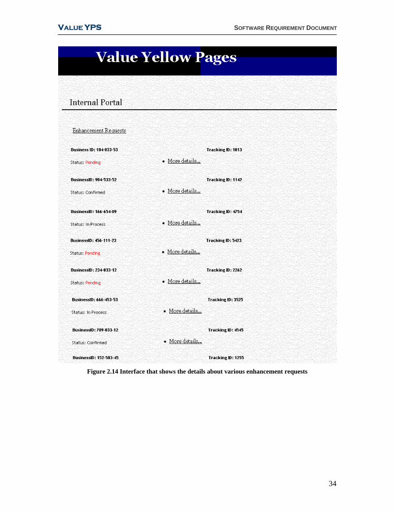
When the manager chooses the ‘View Enhancement Request’, the list of all the requests
stored in the system along with their status is showed in the interface. As soon as a
request is submitted by the BR, it goes to the pending status until the manager processes
the request and changes the status to Confirmed. The manager interfaces are shown in
Figures 2.12-2.14.
Figure 2.12 Manager’s main interface
32

VALUE YPS SOFTWARE REQUIREMENT DOCUMENT
Figure 2.13 Interface showing the details of the updates made to ValueYPS
33
VALUE YPS SOFTWARE REQUIREMENT DOCUMENT
Figure 2.14 Interface that shows the details about various enhancement requests
34

VALUE YPS SOFTWARE ARCHITECTURE DOCUMENT
Software Architecture
document
For Value YPS
35

VALUE YPS SOFTWARE ARCHITECTURE DOCUMENT
TABLE OF CONTENTS
3.1 Architecture Overview .................................................................................................... 38
3.2 Architectural Model ........................................................................................................... 39
3.2.1 The Layered Architecture .................................................................................... 39
3.2.2 Number Of Tiers ........................................................................................................ 39
3.2.2.1 The Client Tier.......................................................................................... 39
3.2.2.2 The Web Server........................................................................................ 41
3.2.2.3 Web Tier ...................................................................................................... 43
3.2.2.4 Domain Tier ............................................................................................... 43
3.2.2.5 Data Access Tier .................................................................................... 44
3.2.2.6 Data Source Tier ..................................................................................... 44
3.3 Underlying Architectural View: Rup 4+1 ....................................................... 45
3.4 Use Case View: High Risk Factors ...................................................................... 45
3.4.1 Functional High Risk Requirements ............................................................... 45
3.4.2 Non-Functional High Risks................................................................................... 46
3.5 Logical View ............................................................................................................................. 47
3.5.1 Web Tier Responsibility List ............................................................................... 50
3.5.2 Class Diagram: Domain And Technical ......................................................... 51
3.6 Process View ................................................................................................................................ 53
3.6.1 Interaction Diagrams .............................................................................................. 53
3.6.2 Transfer Objects........................................................................................................ 57
3.7 Deployment View .................................................................................................................. 57
3.8 Implementation View ........................................................................................................ 60
36

VALUE YPS SOFTWARE ARCHITECTURE DOCUMENT
LIST OF FIGURES
Figure 3.1 High-level view of the YPS 38
Figure: 3.2 Layer-architectural representation of the YPS 40
Figure 3.3 The model, view and controller in MVC architecture 42
Figure 3.4 Representation of the functions of the Web Server using MVC
pattern 43
Figure 3.5 RUP 4+1 Architectural Views 45
Figure 3.6 Risk Intensity shown in the Use-Case perspective 46
Figure 3.7 Logical View of Value YPS 49
Figure 3.8 Class Diagram for Value YPS 52
Figure 3.9 Process View for Value YPS 54
Figure 3.10 Interaction Diagram for SearchRequest Thread 55
Figure 3.11 Interaction Diagram for UpdateDBRequest Thread 56
Figure 3.12 Deployment View for Value YPS 59
Figure 3.13 Implementation view of Value YPS 60
37

VALUE YPS SOFTWARE ARCHITECTURE DOCUMENT
SOFTWARE ARCHITECTURE DOCUMENT
Introduction This document provides a high level overview of the technical architecture for the Value
YPS. The Value YPS is explained using the n-Tier layer architectural pattern, n being
five here. While the Client-Tier and the Data-Tier are explained by relating them to the
client side and the database respectively, the intermediate layers Web-Tier, Domain-Tier
and the Data Access-Tier are explained using the MVC model.
3.1 Architecture Overview The Value YPS enterprise application has a Website through which it presents an
interface to Searchers and BRs. Managers use internal system portal to maintain business
listings and perform other managerial tasks. Each class of users has access to specific
categories of functionality, and each interacts with the application through a specific user
interface mechanism. Figure 3.1 provides a high-level view of the business or real-world
problem that the application is intended to solve.
Figure 3.1: High-level view of the YPS
38

VALUE YPS SOFTWARE ARCHITECTURE DOCUMENT
3.2 Architectural Model As with any software projects, the objective of our development team is to create a
flexible and scalable application composed of a number of functionally independent
modules based on a framework of reusable components.
3.2.1 The Layered Architecture
In order to ensure the application's portability and ability to scale up if needed, the overall
architecture would need to be layered i.e. split into two or more tiers that would reduce
the risk of rewriting the whole application if some of the underlying technologies become
obsolete or inadequate to our needs.
Layering has proved itself in the operating system domain; however, the same benefits
are available when applied to e-commerce or to thin client–oriented applications. Layered
architectures have become essential in supporting the iterative development process by
promoting reusability, scalability, and maintainability.
3.2.2 Number of Tiers
After much thought, we made the decision in favor of a custom n-tier architecture that
took into consideration Value YPS requirements and organization specifics, as opposed
to a more conventional two- or three-tier approach. Figure 3.2 shows the layer
architecture and the order of the layers for Value YPS. The following sections describe
Client Tier, Web Tier, Domain Tier, Data Access Tier and Data Tier.
3.2.2.1 The Client Tier
This is the Presentation layer, and is represented as the Client Tier in our architecture. At
this layer we deploy a thin client architecture for personal computers and Voice-enabled
architecture for mobiles and other hand-held devices. Browser clients (thin) are attractive
for a couple of reasons.
1. They require minimal updating. When an application changes, server-side code has to
change, but browsers are almost always unaffected.
2. They are ubiquitous. Almost every computer has a Web browser.
39

VALUE YPS SOFTWARE ARCHITECTURE DOCUMENT
Voice-enabled wireless handheld clients are useful for the following reasons:
1. They give an alternative means of using the YPS, especially in mobile devices and
PDAs where using a browser on a small screen might be frustrating.
2. They also provide a convenient way to access enterprise resources from the field in
real time.
Web Server
Figure 3.2: Layer-architectural representation of the YPS
40

VALUE YPS SOFTWARE ARCHITECTURE DOCUMENT
3.2.2.2 The Web Server
The Web Tier, Domain Tier and Data Access Tier all reside in the Web server. These
three layers will be implemented using the Model View Controller (MVC) pattern. The
reasons for choosing the MVC architecture to implement the Web Server are:
1. Our development team is more familiar with the MVC model which will make it easy
to implement and maintain.
2. The MVC allows changes in any one layer without affecting any of the other two
layers.
MVC architecture introduces a controller servlet between the client browsers and the JSP
pages/servlet content being delivered. The controller centralizes the logic for dispatching
requests to the next view based on the request URL, input parameters, and application
state. Although the Data Access Tier in our layered architecture does not correspond to
the database of Value YPS, it acts as an intermediate structure to read/write data from/to
the database and therefore we will be consider its functionality to the model in the MVC
pattern.
Motivation for Using MVC
Value YPS’s Web site is a complex application. It has numerous views and pages
displayed to the customer in potentially two different languages, plus content may be
personalized. Customers can make different requests, each of which the application
interprets and services, with data coming from dynamic data sources. The application
dynamically determines the sequence of views to display to the customer.
Applying the Model-View-Controller architecture to Value YPS reduces its complexity
and makes it more manageable. The architecture enhances the degree to which the
application can be maintained and extended. By separating business and control logic
from data presentation, the architecture provides the flexibility to handle such
complexity.
41

VALUE YPS SOFTWARE ARCHITECTURE DOCUMENT
Working Of the Web Server
Figure 3.3 provides the customized MVC architecture for Value YPS. In Value YPS’
Web site, the nature of HTTP requires the client view to use a request-response paradigm
to interact with the model comprising of the layers subsequent to the Web Tier. The
controller section of the MVC architecture controls the flow of the application and serves
as the glue between the model and view—it executes business logic in the model in
response to user requests and helps select the next view to display and forwards it to the
view layer. The view or the client layer will use JSP pages for presentations where the
presentation data changes rather than the structure of the presentation itself. Figure 3.4 is
another perspective of the functionality of the Web-Tier using the MVC pattern.
MODEL
* BussinessListing DB* DB Operations* Concurrency Control* Access Control* Writing Logs* Search Optimization* Data synchronization (between sources)
CONTROLLER
* Get Request* Validate and extract Data from View* Interpret data into DB commands* Send commands to DB* Reorganise data and form HTML* Send HTML to View
VIEW
* Search Request * Display Search Results* Maps and Directions* Enhancement Request Form* Payment Redirection* Manager’s Interface
Model-View-Controller Architecture
State Query
Change Notification
State Change
View Selection
User Gestures
Method Invocations
Events
Figure 3.3 The model, view and controller in MVC architecture
42

VALUE YPS SOFTWARE ARCHITECTURE DOCUMENT
Figure 3.4 Representation of the functions of the Web Server using MVC pattern
3.2.2.3 Web Tier
The Web Tier acts as a controller and view of the MVC model. The controller is basically
a servlet (a Java class) in the web-tier that extends a server, and produces dynamic
content in response to requests from the client. The web-tier also contains the VoiceXML
interpreter to translate the requests coming through WAP.
3.2.2.4 Domain Tier
We have adopted the object oriented approach to decompose each functional
requirement of the business into a set of components or elements called business
(domain) object. Domain objects will be implemented as standard Java classes. Some
examples of domain objects are manager class, business listing class and searcher class.
43

VALUE YPS SOFTWARE ARCHITECTURE DOCUMENT
3.2.2.5 Data Access Tier
One of the most common concerns for Value YPS development is how to extract data
from or update data in a database. Rather than making this behavior part of the domain
object, a second set of objects will be deployed to perform this function. Separating the
behavior out in this way has a number of benefits, including making it possible to change
implementation details, such as database vendor or database schema, without changing
the domain implementation.
3.2.2.6 Data Source Tier
The Data source tier represents the physical database. Value YPS will use a relational
database for storing information about business listings. The primary database will be
backed-up periodically to a backup database. We will also make use of a Directory
Server for maintaining user credentials of managers and BRs. Using two different
databases for storing user credentials and the system data is more efficient as opposed to
using a single database to store everything because the time to authenticate users from a
directory server takes much less time.
Connection Pooling
It is important that application servers and components manage connections efficiently.
Connections are expensive to create and remove. If an application server creates a new
connection for each component’s request, and then destroys the connection when the
component completes its work, it is virtually impossible to support large numbers of
users. To avoid this problem, our servers will support connection pooling. Since Value
YPS has to support thousands of users it is not possible to allow for independent
Database connections to each of them. Therefore the application server will manage a
pool of connections (threads) which will be asynchronously associated with multiple
clients at the same time.
44

VALUE YPS SOFTWARE ARCHITECTURE DOCUMENT
3.3 Underlying Architectural View: RUP 4+1 The underlying architecture of the Value YPS is described using the RUP 4+1[Kruchten
1995] views which are shown in Figure 3.5.
Figure 3.5 RUP 4+1 Architectural Views
RUP view model facilitates an iterative design process with a view to reduce risk. We
have emphasized a lot on stakeholder input and feedback which is the core practice of
RUP. The RUP comprises of the logical, process, physical and development view along
with the use-cases. Each view of RUP is driven by architecturally significant use cases,
nonfunctional requirements in the supplementary specification, and risks. The subsequent
chapters discuss each of these views one by one.
3.4 Use Case View: High Risk Factors Figure 3.6 shows the detailed use case diagram for the sample application. It shows the
potential system actors and their actions along with the risk factor associated with each.
3.4.1 Functional High Risk Requirements
The high risk use cases for Value YPS are:
1. Searches for Business Listing
2. Updates business Listing
This decision has been taken in context of the high priority requirements of allowing the
general public for an easy access to up-to-date business information.
45

VALUE YPS SOFTWARE ARCHITECTURE DOCUMENT
Figure 3.6: Risk Intensity shown in the Use-Case perspective
3.4.2 Non-Functional High Risks
The following are some of the non-functional high risks considered for the Value YPS.
These high-risks are classified by the use-cases which are shown in the use-case diagram
in Figure 3.6.
46

VALUE YPS SOFTWARE ARCHITECTURE DOCUMENT
Use-Case 1: Search for Business Listing
1. All of the searcher's input should be used to do the search (no part data)
2. User's input should not be ill-formatted during normalization
Information should be correctly handed over to and retrieved from Google map
Use-Case 2: Manage Business Listing
1. There should be a disaster recovery plan for the manager due to administrative
purposes
2. Manager login procedure should be encrypted to avoid any password theft.
3. Manager interface should be able to interact with third party systems all the time
4. All the updates relating to BR’s input and payments should be available to the
manager in real time
5. Manager should be able to communicate back and forth with the BRs in order to
respond their feedback
3.5 Logical View The logical view comprises of three components, presentation, domain and the technical
services. The logical view is shown in Figure 3.7. The following table describes each of
the major components of the view along with the motivational factor for including them
in the architecture of Value YPS:
Component Description Motivation for Use 1. Container When the web server application gets a
request for dynamic content (e.g. search results), it will direct the request to the container which will contain the front controller and invoke it according to the request.
Deploying the container allows us to focus our efforts on the business logic instead of worrying about coding for threading, security, JSP processing, and networking.
2. Request Intercepting Filter
Java components used to intercept and process requests before they are sent to the servlet or to process responses before they go back to the client.
Filters perform security checks which allow us to authenticate the clients, and ensure that the clients are accessing the website from a trusted network. Moreover it performs compatibility checks with the browsers of clients as well as their encoding mechanisms.
47

VALUE YPS SOFTWARE ARCHITECTURE DOCUMENT
48
3. Controller The Front Controller architectural design pattern centralizes an application’s request processing and view selection in a single component.
Centralizing control in the controller and reducing business logic in the view promotes code reuse across requests. It is a preferable approach to the alternative-embedding code in multiple views-because that approach may lead to a more error-prone, reuse-by-copy- and-paste environment.
4. Actions The Action objects invoke model operations. They are contained in a hash map maintained by the front controller. The service() method of the controller, using the client request looks up the appropriate Action object in the hash map and invokes its perform method. The Action returns a result object that the servlet uses, along with other data, to decide which view to display next.
An action object simplifies the request fulfilling task by determining the action to perform.
6. Manager The manager classes allow domain objects to invoke database requests without knowledge of the underlying schema.
The separation of concerns allows for reusability and helps in bridging the object-relational gap.
7. Data Access The DAO class provides an abstract API for manipulating a data source.
The DAO manages the connection with the data source to obtain and store data. It provides flexibility to change an application's persistence mechanism over time without the need to re-engineer application logic that interacts with the Data Access Object tier. Moreover, mixing SQL in application logic can cause severe problems. A DAO holds all the SQL for accessing a single table or view: selects, inserts, updates, and deletes. The manager classes call its methods for all interaction with the database.

VALUE YPS SOFTWARE ARCHITECTURE DOCUMENT
49
Figure 3.7: Logical
View of Value YPS

VALUE YPS SOFTWARE ARCHITECTURE DOCUMENT
3.5.1 Web Tier Responsibility List
The following table provides a checklist of responsibilities that the major components of
the web tier will perform:
Task Web Server Container Front Controller
Creates the request and
response objects
Just before starting
The thread.
Calls the
service()method.
The service()method
calls doget() or
doPost
Starts a new thread to
handle requests
Starts a servlet
thread
Converts a response
object to an HTTP
response.
Generates the HTTP
Response stream
from the data in
response object.
Knows HTTP Uses it to talk to
the client
browser.
Adds HTML to the
response object
The dynamic
content for the
client.
Has a reference to the
response objects
Container gives it
the servlet
Uses it to print a
response
Deletes the request and
response objects
Once the servlet is
finished
Coordinates making
dynamic content
Knows how to
forward to the
container
Knows who to call
50

VALUE YPS SOFTWARE ARCHITECTURE DOCUMENT
51
The class diagrams in Figure 3.8 shows the interaction between the business logic and
data access layer objects. Every domain object has a data access object associated with it
which performs the necessary SQL actions on its behalf. Domain objects communicate
with Data Access Objects through the Managing classes called Searcher, Manager, and
Business Representative.
3.5.2 Class Diagram: Domain and Technical

VALUE YPS SOFTWARE ARCHITECTURE DOCUMENT
52
Figure 3.8: Class Diagram for Value YPS

VALUE YPS SOFTWARE ARCHITECTURE DOCUMENT
53
Figure 3.10 and Figure 3.11 show the interaction diagrams for the two most important
threads in the process diagram i.e. the searchrequest and the updateDBrequest thread.
3.6.1 Interaction Diagrams
Figure 3.9 shows the process view of Value YPS. The following steps illustrate the
collaboration among the logical elements that comprise the system:
3.6 Process View
9. The thread completes , and returns to a container managed thread pool, the
container converts the response object into a HTTP response, sends it back to the
client , then deletes the request and response objects.
8. The controller selects the view, adds the request object into it and sends it over the
response object to the container.
7. The domain objects connects to the database and returns the answer, which the
controller adds to the request object.
6. The Front Controller’s job is to pull out data from the request form and create an
action object with that data. It uses a hash map to create the right type of action
and then invokes the perform method. The action object invokes the Get() or Set()
methods of the domain objects based on the request criteria.
5. Depending on the type of request, the service() method calls either the doget() or
doPost() method.
4. The container calls the controller’s service() method.
3. The container allocates a thread for that request, and passes the request, and
response objects to the front controller thread.
2. The container sees that request is for a controller , so the container creates two
objects :
1. The user clicks a link that has a URL to the front controller instead of static page
• HttpServeletRequest
• HttpServletResponse

VALUE YPS SOFTWARE ARCHITECTURE DOCUMENT
54
Figure 3.9: Process View for Value YPS

VALUE YPS SOFTWARE ARCHITECTURE DOCUMENT
55
Figure 3.10: Interaction Diagram for SearchRequest Thread
1: create
:SearchAction:SearchAction
:BusinessListingTO:BusinessListingTO :DataSource
:DataSource
:Searcher:Searcher
:CatagoryDAO:CatagoryDAO
DataSetDataSet
:CatagoryNameTO(String)
:CatagoryNameTO(String)
BusinessListingDA
BusinessListingDA
The method will make a connection to the DB and return a BusinessListingTO containing a set of BusinessListings that match search crieteria
2: get(name,loc,cat)
3: create
4: findCatagoryID(cat)
5: create
6: open connection
7: selectCatID(cat)
8: create
9: execute query
11:
10: create
12: getData()
13: setData()
14: close connection
15:
16: getValue()
17:
18: retrieveBusinessListing(name,loc,catid)
19: create
20: selectBussLis(name,loc,catid)
21: getData() from BussLisTO
22: setData(BusslisTO)
23:

VALUE YPS SOFTWARE ARCHITECTURE DOCUMENT
56
Figure 3.11: Interaction Diagram for UpdateDBRequest Thread
Here GBRS will transfer all records which have been modified, created, deleted after the lastModDate. It will also specify their status. BusinessListingDAO will create a BusinessListingTO and will return it to the Manager Object
:UpdateAction:UpdateAction
:BusinessListingTO:BusinessListingTO
:Manager:Manager
:BusinessListingDAO
:BusinessListingDAO
:Value YPS DataSource:Value YPS DataSource
:GBRS DataSOurce
:GBRS DataSOurce
2: get()
1: create
3: create
4: retrieveUpdatedBussLis()
5: create
7: selectLastModDate()
6: open connection
8: execute query
9:
10: close connection
11:
12: selectBusLis(lastModDate)
13: open connection
14: execute query
16: close connection
15:
17:
18: set()
The retrieved results are shown to the manager on login. As he hits the Update Button, the set() command would be invoked for BusinessListing object so that the changes are permanently saved in the value YPS database
19:

VALUE YPS SOFTWARE ARCHITECTURE DOCUMENT
3.6.2 Transfer Objects
Communication between peer layers (web-domain layers and domain-data access layers)
is carried out through the transfer objects that act as data carriers. For example, a
BusinessListingTO is used as a carrier of user search criteria in the Figure 3.10. The use
of such Transfer Objects allows the client to pass/receive multiple attribute values in a
single remote method invocation. The receiving layer to the enterprise bean to request the
Transfer Object instead of numerous remote method calls to get individual attribute
values.
3.7 Deployment View We are using Linux as Operating System and Apache as web server because they are
suitable to have secure communication and are comparatively low-cost. Linux also
provides the advantage of longer uptime. This reflects one of the significant requirements
of having the website up and running 24/7. The clients are expected to send client
requests as a form of HTTP or WAP requests. The request is then transmitted to TomCat
servlet container which implements the servlets and the JSP specifications. It provides an
environment to run Java code with Apache. We are using TomCat6 which implements
the Servlet 2.5 and JSP 2.1 specifications.
All our servers and back up servers are designed with Dell PowerEdge 6xxx series
because it works well with second generation dual-core 64-bit Intel Xeon 7100 series
processors MP with 800MHz FSB, DDR-2 memory. It also interacts well with Oracle
Database 10g and has Linux OS installed in it by default. As YPS has to keep all the
business listings and corresponding details, internal memory is a big issue. Dell
PowerEdge 6800 is designed to manage up to 3.6 TB (tera byte) of internal memory.
Another attraction of PowerEdge 6800 is that it comes with free Dell OpenManager
software which is a good tool for monitoring, installing and easy management of Value
YPS server.
Though it’s widely believed that Oracle is expensive and too complex, we decided to use
it for Value YPS because it’s robust and flexible. For optimal load balancing, Oracle’s
automated storage management enables a single storage pool to be shared by multiple
57

VALUE YPS SOFTWARE ARCHITECTURE DOCUMENT
58
databases. As BRs are giving credit card information over our site, it’s our responsibility
to ensure security and Oracle is the best choice for that because we can configure system
security parameters to prevent misuse and data-theft. Oracle’s advanced security option
provides network encryption technique which allows to have encrypted data passing
between clients and databases, between databases and middle-tier and among the
databases. It also gives the option for the managers to get restricted use SSL license for
protecting administrative data.
As a directory server, we are using Netscape IPlanet primarily because it’s integrated
with Red Hat Enterprise Server product. All our authentication information from BRs and
managers are stored in this directory server. Using a directory server for authentication
was a decision made for performance reasons. There is also a back up server and
connected database because we need to keep the monthly and yearly backups into this
backup server from the main server. The backup database server reflects on the
requirement of data reliability. It is an important issue and thus this level of redundancy
needs to be built into your application, especially at the data level.
The deployment view is shown in Figure 3.12.

VALUE YPS SOFTWARE ARCHITECTURE DOCUMENT
59Figure 3.12: Deployment View for Value YPS

VALUE YPS SOFTWARE ARCHITECTURE DOCUMENT
3.8 Implementation View The directory structure for Yellow YPS is shown in Figure 3.13.
tomcat
webapps
YPSRoot
WEB-INF
lib classes
Tomcat-specific
Application-specific
This is TomCat home directory
-------------------------------------------------------------------------------------------------------------------------------------------------
-------------------------------------------------------------------------------------------------------------------------------------------------
This must be directly inside the TomCat home directory It is the name of
the web application. This directory name also represents the 'context root' which TomCat uses when resolving URLs
Front Controller Specific
Few of the classes are shown here.
These are the same classes that appear in
the class diagram,
implemented in java.
Figure 3.13 Implementation view of Value YPS
60

VALUE YPS GLOSSARY
Glossary YPS Yellow Pages system
BR Business Representative
Thin client A client presenting only views
PDA Personal digital assistant
GBRS Government Business Registration System
DAO Data Access Object
DTO/TO Data Transfer object/Transfer Object
ISO International Organization for Standardization
Stakeholder People who are involved with and care about the YPS project
MTTR Measure of maintainability; average time required to perform
corrective maintenance on all of the removable items in a system
Latency Delay between the moment something is initiated and the moment
its first effect begins
Authentication Validation of the user credentials while logging in
Enhancement
request
A request to add additional information such as the
website, email, logo of the business, etc to the business listing in the
YPS
Business
listing
A listing on the Value YPS website that comprises of
at-least the company name, phone number and address
Pending
Request list
List of enhancement requests to be processed by the manager
Basic search
criteria
Search for businesses using business names and/or
location of the businesses
Encryption Process of transforming information to make it unreadable to anyone
except those possessing special knowledge
State of the art Highest level of development, as of a technique, or scientific field,
achieved at a particular time
61

VALUE YPS GLOSSARY
Enterprise Process by which new companies are formed and new products and
services are created and brought to market
Third Party GBRS, Google-Maps and payment systems
62

VALUE YPS REFERENCES
References [1] Craig Larman, Applying UML and Patterns: An Introduction to Object-Oriented
Analysis and Design and Iterative Development, Prentice Hall PTR, 2005
[2] Brett McLaughlin, Building Java Enterprise Applications, O’Reilly & Associates,
Inc., 2002
[3] Bryan Basham, Head First Servlets & JSP, O’Reilly & Associates, Inc., 2004
[4] Philippe Kruchten. Architectural Blueprints—The “4+1” View Model of Software
Architecture. IEEE Software. , IEEE Computer Society, Nov 1995, pp. 42 - 50
[5] Martin Fowler, Patterns of Enterprise Application Architecture, Addison-Wesley,
2003
[6] Deepak Alur, John Crupi and Dan Malks, Core J2EE Patterns: Best Practices and
Design Strategies, Prentice Hall / Sun Microsystems Press, First Edition, 2001.
[7] Inderjeet Singh Beth Stearns Mark Johnson, Designing Enterprise Applications
with the J2EETM Platform, Second Edition, Addison-Wesley, 2002
63