Embed Size (px)
Citation preview
Valve bank type BAto allow combination of various different directional valves with connection hole pattern NG 6 conforming DIN 24 340-A6
D 7788Valve bank type BA
November 2009-05© 1999 by HAWE Hydraulik
HAWE HydrAulik SESTREITFELDSTR. 25 • 81673 MÜNCHEN
2.1
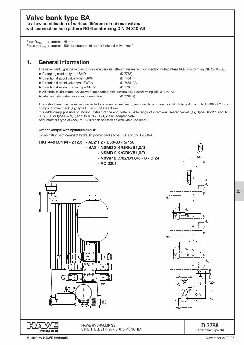
Flow Qmax = approx. 25 lpmPressure pmax = approx. 400 bar (dependent on the installed valve types)
1. General informationThe valve bank type BA serves to combine various different valves with connection hole pattern NG 6 conforming DIN 24340-A6o Clamping module type NSMD (D 7787)o Directional spool valve type NSWP (D 7451 N)o Directional spool valve type SWPN (D 7451 PA)o Directional seated valves type NBVP (D 7765 N)o All kinds of directional valves with connection hole pattern NG 6 conforming DIN 24340-A6o Intermediate plates for series connection (D 7788 Z)
This valve bank may be either connected via pipes or be directly mounted to a connection block type A... acc. to D 6905 A/1 of a compact power pack (e.g. type HK acc. to D 7600 ++).It is additionally possible to mount, instead of the end plate, a wide range of directional seated valves (e.g. type BVZP 1 acc. to D 7785 B or type BWN(H) acc. to D 7470 B/1) via an adapter plate.Accumulators type AC acc. to D 7969 can be fitted as well when required.
Order example with hydraulic circuit:
Combination with compact hydraulic power packs type HKF acc. to D 7600-4.
HKF 449 D/1 M - Z12,3 - AL21F2 - E50/60 - 5/150 - BA2 - NSMD 2 K/GRK/B1,0/0 - NSMD 2 K/GRK/B1,0/0 - NSWP 2 G/02/B1,0/0 - 8 - G 24 - AC 2001

D 7788 page 2
2. Available versions2.1 Connection block and end plate
BA2 A5 - NBVP 16 G /3 - NSWP 2 D03/MP/NZP 16 Q33 /1 - CZ 5R/180/5R - NBVP 16 G/ABR0,8 BBR1,0/M /0 - 1 - G 24
Table 1: Basic type and connection block
Basic type
BA2
BA2 A5
BA2 A8
BA2 A9
Connection block (version)
Suited for direct mounting to con-nection blocks type A (D 6905 A/1) for combination with compact hydraulic power packstype HK D 7600 ++ HC(G) D 7900, D 7900 G MP D 7200 H
Version for pipe connection
Like version BA2 A5 but with additional check valve at R
Blanking plate, when P and R connection takes place via an intermediate or an end plate.
Symbol
(without)
Table 3 End plates(page 3)
Table 4 Directional valves(page 4)
Table 5 Sub-plates(page 5)
Table 2: Solenoid voltage (applies to all solenoids of the valve bank!)
With plug
G 12
G 24
WG 110 1)
WG 230 1)
Without plug
X 12
X 24
X 98 1)
X 205 1)
Plug with LED
L 12
L 24, L5K 24 2), L10K 24 2)
---
---
Nom. voltage
12 V DC
24 V DC
110 V AC 50/60 Hz
230 V AC 50/60 Hz
1) Solenoids 98 V DC or 205 V DC, as a rectifier circuit is usually integrated in the plug
2) Version L5 K24 and L10 K24 come with cable length 5 or 10 m, see also D 7163
Order example:
Order example with hydraulic circuit: (Combination with intermediate plates acc. to D 7788 Z)
BA2 A5 - NBVP 16 G/AB1,0-M /NZP 16 PDM 2-44/24 /3 - NBVP 16 Z/2-M /NZP 16 Q10 /3 - CZ 2H/180/5 - NSWP 2 G 12/MP/R/20 /1 - NSWP 2 W/M/R/80/S /0 - 48/7 - G 24
D 7788 page 3
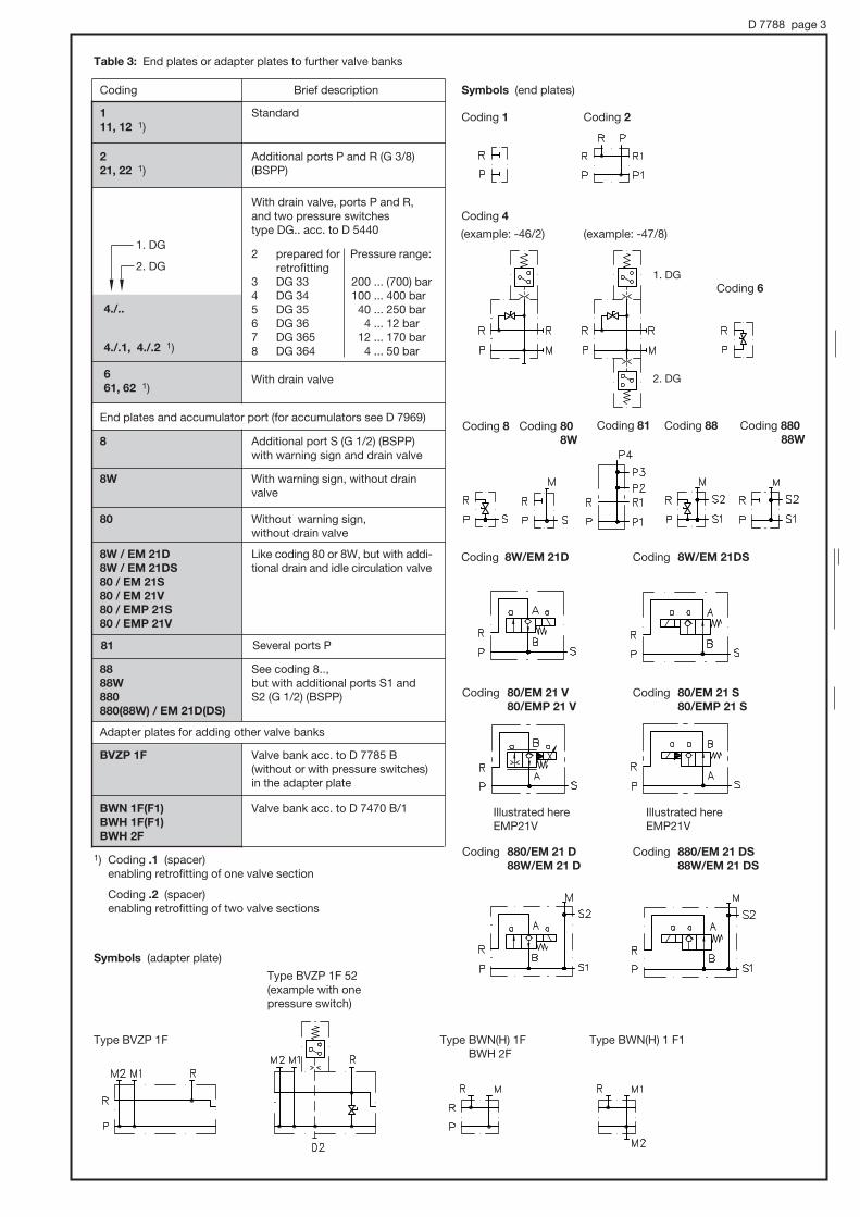
Table 3: End plates or adapter plates to further valve banks
Coding Brief description Symbols (end plates)
111, 12 1)
4./.1, 4./.2 1)
221, 22 1)
8
8W
80
8W / EM 21D8W / EM 21DS80 / EM 21S80 / EM 21V80 / EMP 21S80 / EMP 21V
8888W880880(88W) / EM 21D(DS)
BVZP 1F
BWN 1F(F1)BWH 1F(F1)BWH 2F
End plates and accumulator port (for accumulators see D 7969)
Adapter plates for adding other valve banks
Standard
With drain valve
Additional ports P and R (G 3/8)(BSPP)
Additional port S (G 1/2) (BSPP) with warning sign and drain valve
With warning sign, without drain valve
Without warning sign, without drain valve
Like coding 80 or 8W, but with addi-tional drain and idle circulation valve
See coding 8.., but with additional ports S1 and S2 (G 1/2) (BSPP)
Valve bank acc. to D 7785 B (without or with pressure switches)in the adapter plate
Valve bank acc. to D 7470 B/1
1) Coding .1 (spacer) enabling retrofitting of one valve section
Coding .2 (spacer) enabling retrofitting of two valve sections
2. DG
1. DG
4./..
2 prepared for retrofitting
3 DG 334 DG 345 DG 356 DG 367 DG 3658 DG 364
With drain valve, ports P and R, and two pressure switches type DG.. acc. to D 5440
661, 62 1)
Pressure range:
200 ... (700) bar 100 ... 400 bar 40 ... 250 bar 4 ... 12 bar 12 ... 170 bar 4 ... 50 bar
Coding 1
Coding 4
Coding 80/EM 21 V80/EMP 21 V
Coding 80/EM 21 S80/EMP 21 S
Coding 8W/EM 21D Coding 8W/EM 21DS
Coding 2
Coding 6
Type BVZP 1F Type BWN(H) 1FBWH 2F
Type BWN(H) 1 F1
Type BVZP 1F 52 (example with one pressure switch)
Coding 880/EM 21 D88W/EM 21 D
Coding 880/EM 21 DS88W/EM 21 DS
1. DG
2. DG
(example: -46/2) (example: -47/8)
Symbols (adapter plate)
Illustrated here EMP21V
Illustrated here EMP21V
Coding 8 Coding 88Coding 81Coding 80 8W
Coding 880 88W
81 Several ports P
D 7788 page 4
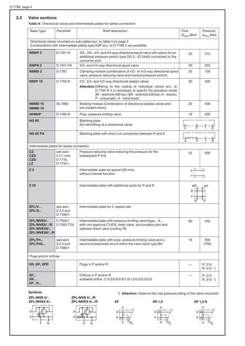
Table 4: Directional valves and intermediate plates for series connection
Basic type Pamphlet Brief description Flow Qmax (lpm)
Pressure pmax (bar)
25 315
16 500
CZCZACZDLZ
see sect. 2.2.1 and D 7745,D 7745 L
Pressure reducing valve reducing the pressure for the subsequent P-line
22 500
Directional valves mounted on sub-plates acc. to table 5 on page 5 (combinations with intermediate plates type NZP acc. to D 7788 Z are possible)
Intermediate plates for series connection
Intermediate plate as spacer (50 mm), without internal function
Z 5
Z 52 Intermediate plate with additional ports for P and R
Plugs and/or orifices
D 7000/1D 7000 TÜV
ZPL/MVE6/..ZPL/MVE6/../RZPL/MVEX6/..ZPL/MVEX6/../R
Intermediate plate with pressure limiting valve (type ...X..: with unit approval (TUEV), drain valve, accumulator port and optional check valve (coding /R)
60 450
see sect. 2.2.3 and D 7485/1
ZPL/P4...ZPL/P45...
Intermediate plate with prop. pressure limiting valve and a second pressurized circuit within the valve bank type BA
16 500(700)
see sect. 2.2.2 and D 7490/1
ZPL/V... ZPL/S...
Intermediate plate for 2. speed rate
XR, XP, XPR Plugs in P and/or R --- P: 315R: 315 1)
--- P: 315 R: 315 1)
XP...XR...XP...R...
Orifices in P and/or Ravailable orifice # 0.5/0.6/0.8/1.0/1.5/2.0/2.5/3.0
Blanking plate (for retrofitting of a directional valve)
Prop. pressure limiting valve
3/2-, 3/3-, 4/2- and 4/3-way directional spool valve with option for an additional pressure switch type DG 3.. (D 5440) connected to the consumer port
Blanking plate with short-cut connection between P and A
NG 6X
NBMD 16
NPMVP
NSWP 2
NG 6X PA
20 400Braking module (Combination of directional seated valves and pre-loaded return)
NBMD 16 Sk 7983
D 7485 N
20 4002/2- 3/2- and 4/3-way directional seated valves
Attention: Differing to the coding of individual valves acc. to D 7765 N it is necessary to specify the actuation mode (M - solenoid 400 bar; GM - solenoid 250 bar; H - draulic; P - pneumatic; A - hand lever)
NBVP 16 D 7765 N
25 100Clamping module (combination of 4/2- or 4/3-way directional spool valve, pressure reducing valve and tracked pressure switch)
NSMD 2 D 7787
50 3503/3- and 4/3-way directional spool valve SWPN 2 D 7451 PA
D 7451 N
2.2 Valve sections
ZPL/MVE 6/../RZPL/MVEX 6/../R
ZPL/MVE 6/..ZPL/MVEX 6/.. XP XR 1,0 XP 1,5 R
Symbols 1) Attention: Observe the max pressure rating of the valve mounted!

D 7788 page 5
Table 5: Sub-plates
Coding Brief description Symbols
/0/01
/1 With additional, releasable check valve at A (type CRH 1 acc. to D 7712)
Standard
1) Port M for pressure gauge required when a clamping module type NSMD acc. to D 7787 or an intermediate plate type NZP acc. to D 7788 Z is mounted, not with version /01
/5 Releasable double check valve
Symbols of directional valves with sub-plate (examples)
NSWP 2 G/M/R/ABV1,0 BBV1,5/70/S/0NBVP 16 G/R/A9/400/B9/700-M/0
NBMD 16 Z/EMP 21S/10/0 NSMD 2 K/GRK/M/0
NBVP 16 Z/R/AB1,5/4/S-M/0
NSWP 2 D06/MP/20/0
1)
/2
/3
With additional throttle at T (type Q 30 acc. to D 7730)
With additional pressure gauge ports MA and MB
1)
/6Arbitrary blockage of gallery P, only available in combination with 2/2-way directional valves, e.g. NBVP 16 S/2-M
NPMVP 4-41/G 24/0
NBVP 16S/2-M/6

D 7788 page 6
2.2.1 Pressure reducing valve at P
Order example: BA2 A5 - ...
- CZ 5 R / 120 / 5R - ...
Basic type
Adjustability
- CZ
- CZA
- CZD
- LZ
Pressure reducing valve; for differences, see dimensional drawings sect. 4.
5
5R
Without check valve in P
With check valve in P(not avail. with type CZD)
Coding
without
R
H 1)
Brief description
Tool adjustable
Manually adjustable
With lock
Pressure setting in bar
Pressure range
Coding
08 1)
1
2
5
25
55
X
Pressure range (bar)
50 ... (400)
30 ... 300
20 ... 200
15 ... 130
8 ... 130
30 ... 130
Prepared for retrofitting
Coding
081 1)
11
21
51
251
551
--
Pressure range (bar)
50 ... (500)
30 ... (380)
20 ... (250)
15 ... 165
8 ... 165
30 ... 165
Flow max. (lpm)
15
15
15
15
6
22
Manually With Tool adjustable lock adjustable
Coding -CZ..
Coding -CZD.. Coding -CZX... -CZAX... -CZDX... -LZX...
(illustrated here type CZX)
Coding -CZA..
Coding -LZ
Check valve at P Coding R
Check valve at P Coding R
Drain valve
Drain valve
Check valve at P Coding R
Drain valve
Pressure reducing valve wi-th safety valve functionality
Pressure reducing valve with direct accumulator port (G 3/8)
1) Not available with type LZ
D 7788 page 7
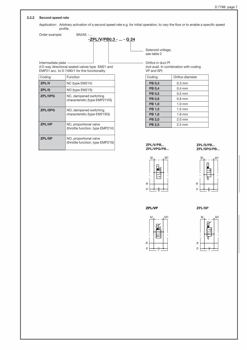
2.2.2 Second speed rate
Application: Arbitrary activation of a second speed rate e.g. for initial operation, to vary the flow or to enable a specific speed profile.
BA2A5 -...
-ZPL/V/PB0.3 - ... - G 24Order example:
Solenoid voltage, see table 2
Orifice in duct Pl(not avail. In combination with coding VP and SP)
Intermediate plate 2/2-way directional seated valves type EM21 and EMP21 acc. to D 7490/1 for this functionality
Coding Function Coding Orifice diameter
PB 0,3
PB 0,4
PB 0,5
PB 0,8
PB 1,0
PB 1,5
PB 1,8
PB 2,0
PB 2,5
0.3 mm
0.4 mm
0.5 mm
0.8 mm
1.0 mm
1.5 mm
1.8 mm
2.0 mm
2.5 mm
ZPL/V/PB...ZPL/VPG/PB...
ZPL/S/PB...ZPL/SPG/PB...
ZPL/V NC (type EM21V)
ZPL/S NO (type EM21S)
ZPL/VPG NC, dampened switching characteristic (type EMP21VG)
ZPL/SPG NO, dampened switching characteristic (type EM21SG)
ZPL/VP NC, proportional valve(throttle function, type EMP21V)
ZPL/SP NO, proportional valve (throttle function, type EMP21S)
ZPL/VP ZPL/SPZPL/VP
D 7788 page 8
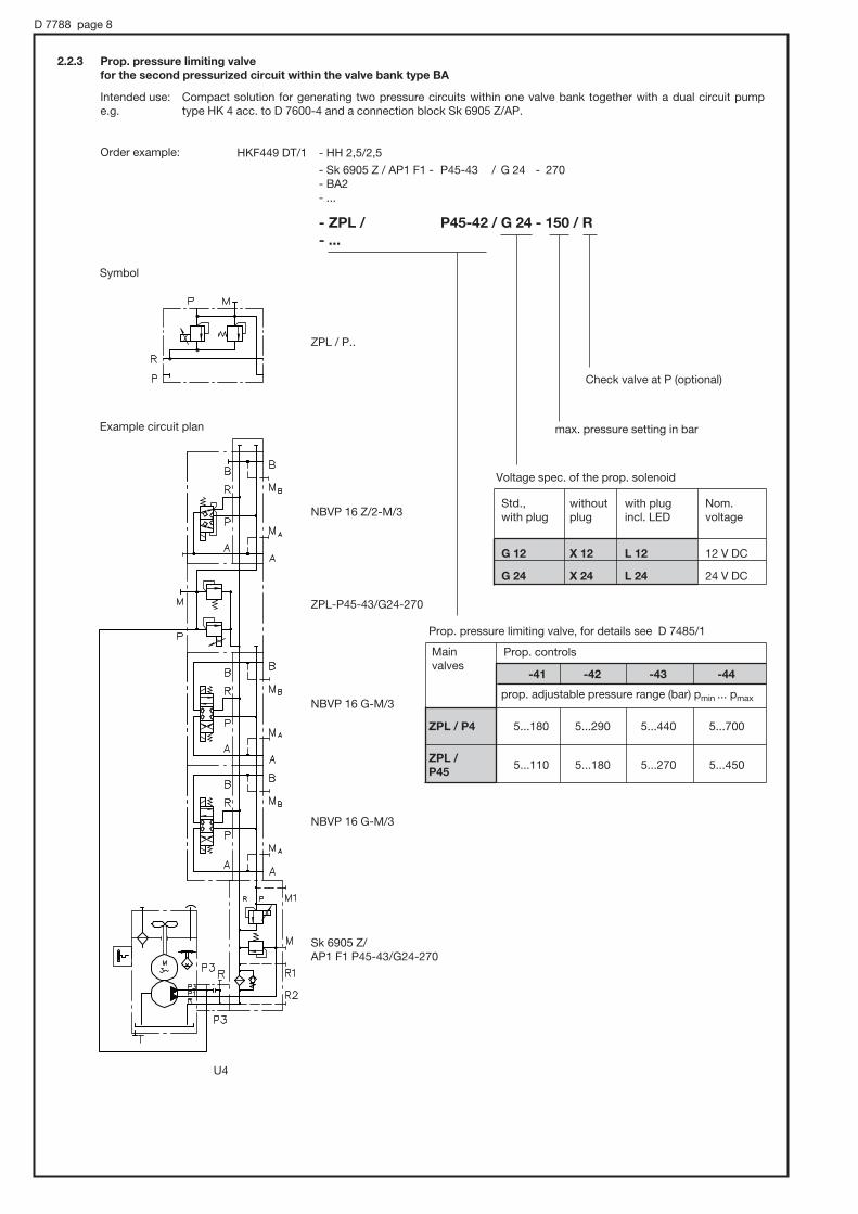
2.2.3 Prop. pressure limiting valve for the second pressurized circuit within the valve bank type BA
Order example:
Intended use: Compact solution for generating two pressure circuits within one valve bank together with a dual circuit pump e.g. type HK 4 acc. to D 7600-4 and a connection block Sk 6905 Z/AP.
Std., without with plug Nom. with plug plug incl. LED voltage
G 12 X 12 L 12 12 V DC
G 24 X 24 L 24 24 V DC
Prop. pressure limiting valve, for details see D 7485/1
Prop. controls
prop. adjustable pressure range (bar) pmin ... pmax
ZPL / P4 5...180 5...290 5...440 5...700
ZPL / P45
5...110 5...180 5...270 5...450
Main valves
-41 -42 -43 -44
Check valve at P (optional)
max. pressure setting in bar
Voltage spec. of the prop. solenoid
NBVP 16 Z/2-M/3
ZPL / P..
ZPL-P45-43/G24-270
NBVP 16 G-M/3
NBVP 16 G-M/3
U4
Sk 6905 Z/AP1 F1 P45-43/G24-270
Symbol
Example circuit plan
HKF449 DT/1 - HH 2,5/2,5
- Sk 6905 Z / AP1 F1 - P45-43 / G 24 - 270 - BA2 - ...
- ZPL / P45-42 / G 24 - 150 / R - ...

D 7788 page 9
3. Additional dataType coding acc. to type coding key
Max. number of valve sections 10
Installed position any
Fastening Thread M8, see dimensional drawings
Ports P, R, A, B = G 3/8 (G 1/4) (BSPP) P = Pump S = G 1/2 (BSPP) R = Return M = G 1/4 (BSPP) A, B = Consumers S = Accumulator M = Pressure gauge
The specifications of the mounted directional valves and/or hydraulic power pack are binding and must not be exceeded
Pressure, flow, pressure fluid, and temperature
Mass (weight) Connection blocks BA 2 A5 (A8) = 0.8 kg A9 = 0.3 kg
End plates 1 = 0.3 kg 2 = 0.8 kg 4 = 1.2 kg 6 = 0.4 kg 8, 80, 8W = 1.0 kg 80(8W) / EM 21D(DS) = 1.3 kg
81 = 0.8 kg 88, 880, 88W = 3.5 kg 880(88W) / EM 21D(DS) = 3.8 kg
Sub-plates /0, /1, /2, /3, /6 = 0.8 kg /5 = 1.4 kg /01 = 0.6 kg
Intermediate plates Z 5 = 0.8 kg Z 52 = 0.9 kg
ZPL/MVE(X)6 = 2.3 kg ZPL/V, ZPL/S = 1.1 kg ZPL/P4, ZPL/P45 = 2.0 kg
CZ, CZA, CZD, LZ = 2.3 kg CZX, CZAX = 1.6 kg
Blanking plate NG 6X = 0.3 kg NG 6X PA = 0.4 kg
Directional valves dep. on type, see resp. pamphlet

D 7788 page 10
4. Unit dimensions All dimensions in mm, subject to change without notice!
4.1 Connection blocks and end plates
Connection blocks Type BA2 A5
BA2 A8
Type BA 2 (without own connection block)
Direct mounting onto connec-tion blocks for compact hydraulic power packs acc. to D 6905 A/1
End plate Coding 1
M8, 12 deep
Valve sections(sect. 4.2)
Type BA2 A9
Spacers
l = 50 with coding 1; Sufficient space for retrofitting of one valve section
l = 100 with coding 2; Sufficient space for retrofitting of two valve sections
Ports conf. ISO 228/1 (BSPP):P, R, A, and B = G 3/8
a/f 10 torque 9.5 Nma/f 10
M8, 12 deep
approx. 11.5
approx. 7

D 7788 page 11
Coding 2 Coding 6Coding 4
End plates
Ports conf. ISO 228/1 (BSPP):P, R, P1, R1 = G 3/8
M8, 12 deep
Drain valve a/f 5
Coding 2 (prepared for retrofitting of a second pressure switch)
Coding 8 Coding 80 8W
Ports conf. ISO 228/1 (BSPP):S = G 1/2
Drain valve a/f 5
Coding 80 / EM 21V(S)8W / EM 21D(DS)80 / EMP 21V(S)
Coding 81
Ports P, M = G 1/4 (BSPP)
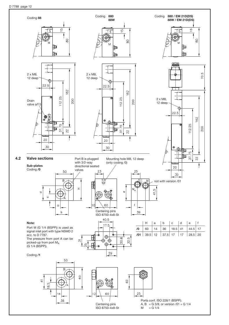
D 7788 page 12
Coding 88 Coding 880 88W
Coding 880 / EM 21D(DS) 88W / EM 21D(DS)
Drain valve a/f 5
2 x M8,12 deep
2 x M8,12 deep
2 x M8,12 deep
Port B is plugged with 3/2-way directional seated valves
not with version /01
Note:
Port M (G 1/4 (BSPP)) is used as signal inlet port with type NSMD 2 acc. to D 7787.The pressure from port A can be picked-up from port MA (G 1/4 (BSPP)).
H a b c d e f
/0 60 14 36 18.5 41 44.5 17
/01 39.5 12 37.5 17 17 28.5 20
4.2 Valve sections
Sub-plates Coding /0
Coding /1
Centering pins ISO 8750-4x8-St
Centering pins ISO 8750-4x8-St
Ports conf. ISO 228/1 (BSPP):A, B = G 3/8, or version /01 = G 1/4M = G 1/4
Mounting hole M8, 12 deep (only coding /0)
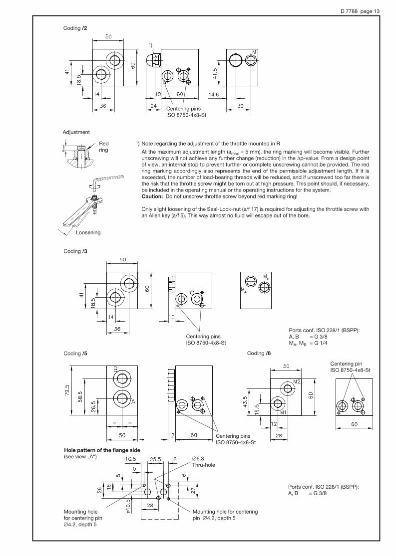
D 7788 page 13
Coding /2
Centering pins ISO 8750-4x8-St
1) Note regarding the adjustment of the throttle mounted in R
At the maximum adjustment length (amax = 5 mm), the ring marking will become visible. Further unscrewing will not achieve any further change (reduction) in the |p-value. From a design point of view, an internal stop to prevent further or complete unscrewing cannot be provided. The red ring marking accordingly also represents the end of the permissible adjustment length. If it is exceeded, the number of load-bearing threads will be reduced, and if unscrewed too far there is the risk that the throttle screw might be torn out at high pressure. This point should, if necessary, be included in the operating manual or the operating instructions for the system.
Caution: Do not unscrew throttle screw beyond red marking ring!
Only slight loosening of the Seal-Lock-nut (a/f 17) is required for adjusting the throttle screw with an Allen key (a/f 5). This way almost no fluid will escape out of the bore.
Adjustment
Red ring
Loosening
1)
Mounting hole for centering pin #4.2, depth 5
Mounting hole for centering pin #4.2, depth 5
Hole pattern of the flange side (see view „A“)
Coding /3
Coding /5
Centering pins ISO 8750-4x8-St
Ports conf. ISO 228/1 (BSPP):A, B = G 3/8MA, MB = G 1/4
Ports conf. ISO 228/1 (BSPP):A, B = G 3/8
#6.3 Thru-hole
Coding /6
Centering pinISO 8750-4x8-St
14.6
Centering pins ISO 8750-4x8-St

D 7788 page 14
Centering pins ISO 8750-4x8-St
Hole pattern of the flange side see page 12!
Intermediate plates for series connection
Coding Z 5
Coding Z 52
Ports conf. ISO 228/1 (BSPP): P, R = G 3/8MP, MR = G 1/4
Blanking plate coding NG 6 X and NG 6 X PA (for connection hole pattern NG 6, DIN 24340-A6)
Max. torque 5 Nm
Sealing of ports via O-rings NBR 90 Sh:A, B, P, R 9.25x1.78 M 2.9x1.78
Centering pins ISO 8750-4x8-St
Coding H (with lock)
Ports conf. ISO 228/1 (BSPP):M4, M5, and M6 = G 1/4
Drain valve a/f 5
Blocked with tapped plug at type CZAX
Tool adjustable
Coding R (Manually adjustable)
Type a
NG 6 X 15
NG 6 X PA 20
app
rox.
23.
5
Pressure reducing valve
Type CZA
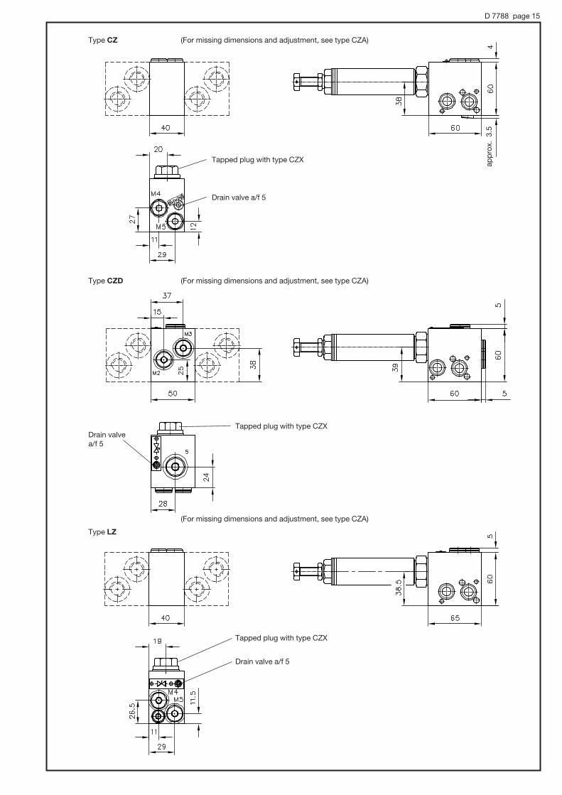
D 7788 page 15
Type CZD
(For missing dimensions and adjustment, see type CZA)
(For missing dimensions and adjustment, see type CZA)
Drain valve a/f 5
Tapped plug with type CZX
(For missing dimensions and adjustment, see type CZA)
Tapped plug with type CZX
Drain valve a/f 5
Drain valve a/f 5
Tapped plug with type CZX
Type LZ
Type CZ
app
rox.
3.5

D 7788 page 16
Type Nomenclature Order coding
XP, XR Blanking shim 6905 018
XP 0.5, XR 0.5 Orifice 6905 018-0.5XP 0.6, XR 0.6 Orifice 6905 018-0.6XP 0.8, XR 0.8 Orifice 6905 018-0.8XP 1.0, XR 1.0 Orifice 6905 018-1.0XP 1.5, XR 1.5 Orifice 6905 018-1.5XP 2.0, XR 2.0 Orifice 6905 018-2.0XP 2.5, XR 2.5 Orifice 6905 018-2.5XP 3.0, XR 3.0 Orifice 6905 018-3.0
Pressure limiting valves Type ZPL/MVE 6 ZPL/MVEX 6
Second speed rate Type ZPL/V... ZPL/S...
Pressure limiting valves are lead sealed with type MVEX
Drain valve a/f 5
Blanking shims and orifices
Order coding
Prop. pressure limiting valve Type ZPL / P4... ZPL / P45...
approx. 72.5
approx. 94
app
rox.
99.
5