Embed Size (px)
Citation preview
Shut-off and Control Valves - Series 8000 Valve 10- 30.3 - 5E - i - 9/08
Valve Model Number Description
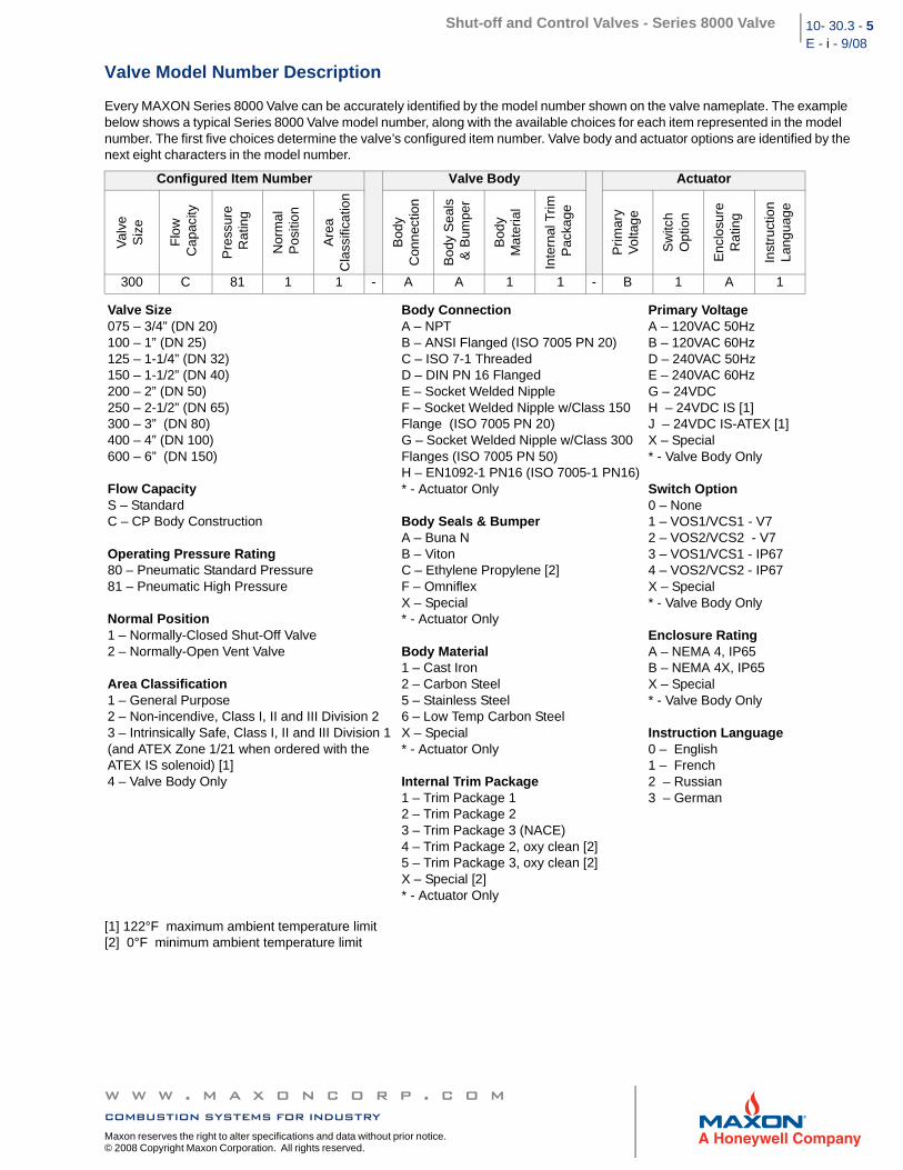
Every MAXON Series 8000 Valve can be accurately identified by the model number shown on the valve nameplate. The example below shows a typical Series 8000 Valve model number, along with the available choices for each item represented in the model number. The first five choices determine the valve’s configured item number. Valve body and actuator options are identified by the next eight characters in the model number.
[1] 122°F maximum ambient temperature limit[2] 0°F minimum ambient temperature limit
Configured Item Number Valve Body Actuator
Val
ve
Siz
e
Flo
w C
apac
ity
Pre
ssur
e R
atin
g
Nor
mal
Pos
ition
Are
a C
lass
ifica
tion
Bod
yC
onne
ctio
n
Bod
y S
eals
& B
umpe
r
Bod
yM
ater
ial
Inte
rnal
Trim
Pac
kage
Prim
ary
Vol
tage
Sw
itch
Opt
ion
Enc
losu
reR
atin
g
Inst
ruct
ion
Lang
uage
300 C 81 1 1 - A A 1 1 - B 1 A 1
Valve Size 075 – 3/4” (DN 20) 100 – 1” (DN 25)125 – 1-1/4” (DN 32) 150 – 1-1/2” (DN 40) 200 – 2” (DN 50) 250 – 2-1/2” (DN 65)300 – 3” (DN 80)400 – 4” (DN 100) 600 – 6” (DN 150)
Flow Capacity S – Standard C – CP Body Construction
Operating Pressure Rating80 – Pneumatic Standard Pressure 81 – Pneumatic High Pressure
Normal Position 1 – Normally-Closed Shut-Off Valve 2 – Normally-Open Vent Valve
Area Classification1 – General Purpose 2 – Non-incendive, Class I, II and III Division 2 3 – Intrinsically Safe, Class I, II and III Division 1 (and ATEX Zone 1/21 when ordered with the ATEX IS solenoid) [1] 4 – Valve Body Only
Body Connection A – NPT B – ANSI Flanged (ISO 7005 PN 20) C – ISO 7-1 Threaded D – DIN PN 16 Flanged E – Socket Welded Nipple F – Socket Welded Nipple w/Class 150 Flange (ISO 7005 PN 20)G – Socket Welded Nipple w/Class 300 Flanges (ISO 7005 PN 50) H – EN1092-1 PN16 (ISO 7005-1 PN16)* - Actuator Only
Body Seals & Bumper A – Buna N B – Viton C – Ethylene Propylene [2]F – OmniflexX – Special * - Actuator Only
Body Material 1 – Cast Iron 2 – Carbon Steel 5 – Stainless Steel 6 – Low Temp Carbon SteelX – Special * - Actuator Only
Internal Trim Package 1 – Trim Package 1 2 – Trim Package 2 3 – Trim Package 3 (NACE)4 – Trim Package 2, oxy clean [2]5 – Trim Package 3, oxy clean [2]X – Special [2]* - Actuator Only
Primary Voltage A – 120VAC 50Hz B – 120VAC 60Hz D – 240VAC 50Hz E – 240VAC 60Hz G – 24VDC H – 24VDC IS [1]J – 24VDC IS-ATEX [1]X – Special * - Valve Body Only
Switch Option 0 – None 1 – VOS1/VCS1 - V7 2 – VOS2/VCS2 - V73 – VOS1/VCS1 - IP674 – VOS2/VCS2 - IP67X – Special * - Valve Body Only
Enclosure Rating A – NEMA 4, IP65 B – NEMA 4X, IP65X – Special * - Valve Body Only
Instruction Language 0 – English1 – French 2 – Russian3 – German
w w w . m a x o n c o r p . c o mcombustion systems for industry
Maxon reserves the right to alter specifications and data without prior notice. © 2008 Copyright Maxon Corporation. All rights reserved.
Shut-off and Control Valves - Series 8000 Valve10-30.3-6E -i - 9/08
Valve Body Assembly Options & Specifications
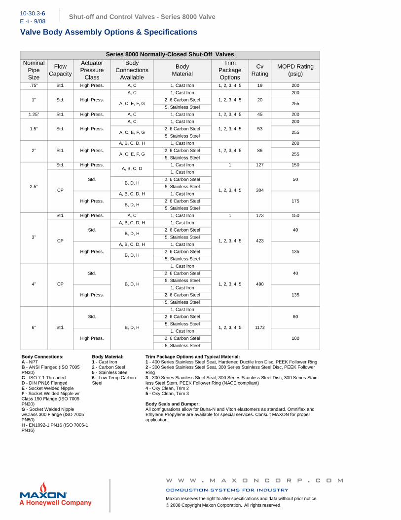
Series 8000 Normally-Closed Shut-Off ValvesNominal
Pipe Size
FlowCapacity
ActuatorPressure
Class
Body Connections
Available
BodyMaterial
Trim Package Options
CvRating
MOPD Rating (psig)
.75” Std. High Press. A, C 1, Cast Iron 1, 2, 3, 4, 5 19 200
1” Std. High Press.
A, C 1, Cast Iron
1, 2, 3, 4, 5 20
200
A, C, E, F, G2, 6 Carbon Steel
255 5, Stainless Steel
1.25” Std. High Press. A, C 1, Cast Iron 1, 2, 3, 4, 5 45 200
1.5” Std. High Press.
A, C 1, Cast Iron
1, 2, 3, 4, 5 53
200
A, C, E, F, G2, 6 Carbon Steel
255 5, Stainless Steel
2” Std. High Press.
A, B, C, D, H 1, Cast Iron
1, 2, 3, 4, 5 86
200
A, C, E, F, G2, 6 Carbon Steel
255 5, Stainless Steel
2.5”
Std. High Press.A, B, C, D
1, Cast Iron 1 127 150
CP
Std.
1, Cast Iron
1, 2, 3, 4, 5 304
50 B, D, H
2, 6 Carbon Steel
5, Stainless Steel
High Press.
A, B, C, D, H 1, Cast Iron
175 B, D, H
2, 6 Carbon Steel
5, Stainless Steel
3”
Std. High Press. A, C 1, Cast Iron 1 173 150
CP
Std.
A, B, C, D, H 1, Cast Iron
1, 2, 3, 4, 5 423
40 B, D, H
2, 6 Carbon Steel
5, Stainless Steel
High Press.
A, B, C, D, H 1, Cast Iron
135 B, D, H
2, 6 Carbon Steel
5, Stainless Steel
4” CP
Std.
B, D, H
1, Cast Iron
1, 2, 3, 4, 5 490
40 2, 6 Carbon Steel
5, Stainless Steel
High Press.
1, Cast Iron
135 2, 6 Carbon Steel
5, Stainless Steel
6” Std.
Std.
B, D, H
1, Cast Iron
1, 2, 3, 4, 5 1172
60 2, 6 Carbon Steel
5, Stainless Steel
High Press.
1, Cast Iron
100 2, 6 Carbon Steel
5, Stainless Steel
Body Connections:A - NPTB - ANSI Flanged (ISO 7005 PN20)C - ISO 7-1 ThreadedD - DIN PN16 FlangedE - Socket Welded NippleF - Socket Welded Nipple w/Class 150 Flange (ISO 7005 PN20)G - Socket Welded Nipplew/Class 300 Flange (ISO 7005 PN50)H - EN1092-1 PN16 (ISO 7005-1 PN16)
Body Material:1 - Cast Iron2 - Carbon Steel5 - Stainless Steel6 - Low Temp Carbon Steel
Trim Package Options and Typical Material:1 - 400 Series Stainless Steel Seat, Hardened Ductile Iron Disc, PEEK Follower Ring2 - 300 Series Stainless Steel Seat, 300 Series Stainless Steel Disc, PEEK Follower Ring3 - 300 Series Stainless Steel Seat, 300 Series Stainless Steel Disc, 300 Series Stain-less Steel Stem, PEEK Follower Ring (NACE compliant)4 - Oxy Clean, Trim 25 - Oxy Clean, Trim 3
Body Seals and Bumper:All configurations allow for Buna-N and Viton elastomers as standard. Omniflex andEthylene Propylene are available for special services. Consult MAXON for proper application.
w w w . m a x o n c o r p . c o mcombustion systems for industryMaxon reserves the right to alter specifications and data without prior notice.
© 2008 Copyright Maxon Corporation. All rights reserved.
Shut-off and Control Valves - Series 8000 Valve 10- 30.3 - 7E - i - 9/08
Valve Body Assembly Options & Accessories
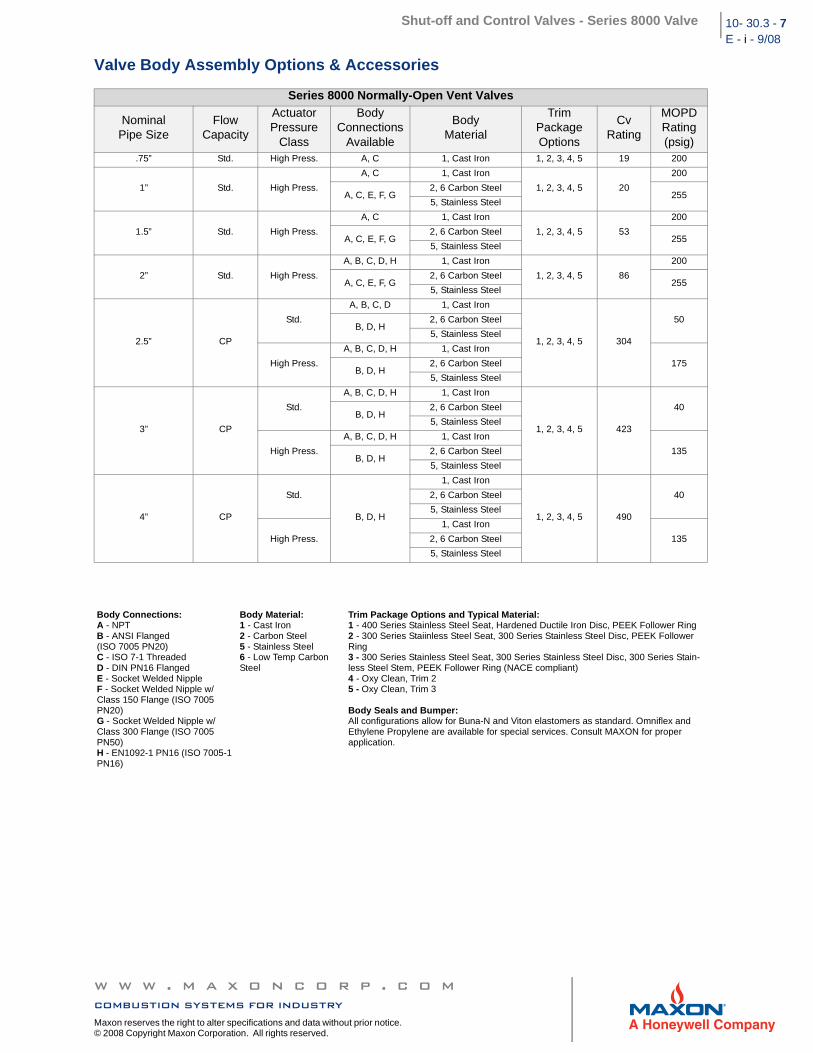
Series 8000 Normally-Open Vent Valves
NominalPipe Size
FlowCapacity
ActuatorPressure
Class
BodyConnections
Available
BodyMaterial
TrimPackageOptions
CvRating
MOPDRating(psig)
.75” Std. High Press. A, C 1, Cast Iron 1, 2, 3, 4, 5 19 200
1” Std. High Press.
A, C 1, Cast Iron
1, 2, 3, 4, 5 20
200
A, C, E, F, G2, 6 Carbon Steel
255 5, Stainless Steel
1.5” Std. High Press.
A, C 1, Cast Iron
1, 2, 3, 4, 5 53
200
A, C, E, F, G2, 6 Carbon Steel
255 5, Stainless Steel
2” Std. High Press.
A, B, C, D, H 1, Cast Iron
1, 2, 3, 4, 5 86
200
A, C, E, F, G2, 6 Carbon Steel
255 5, Stainless Steel
2.5” CP
Std.
A, B, C, D 1, Cast Iron
1, 2, 3, 4, 5 304
50 B, D, H
2, 6 Carbon Steel
5, Stainless Steel
High Press.
A, B, C, D, H 1, Cast Iron
175 B, D, H
2, 6 Carbon Steel
5, Stainless Steel
3” CP
Std.
A, B, C, D, H 1, Cast Iron
1, 2, 3, 4, 5 423
40 B, D, H
2, 6 Carbon Steel
5, Stainless Steel
High Press.
A, B, C, D, H 1, Cast Iron
135 B, D, H
2, 6 Carbon Steel
5, Stainless Steel
4” CP
Std.
B, D, H
1, Cast Iron
1, 2, 3, 4, 5 490
40 2, 6 Carbon Steel
5, Stainless Steel
High Press.
1, Cast Iron
135 2, 6 Carbon Steel
5, Stainless Steel
Body Connections:A - NPTB - ANSI Flanged (ISO 7005 PN20)C - ISO 7-1 ThreadedD - DIN PN16 FlangedE - Socket Welded NippleF - Socket Welded Nipple w/Class 150 Flange (ISO 7005 PN20)G - Socket Welded Nipple w/Class 300 Flange (ISO 7005 PN50)H - EN1092-1 PN16 (ISO 7005-1 PN16)
Body Material:1 - Cast Iron2 - Carbon Steel5 - Stainless Steel6 - Low Temp Carbon Steel
Trim Package Options and Typical Material:1 - 400 Series Stainless Steel Seat, Hardened Ductile Iron Disc, PEEK Follower Ring2 - 300 Series Staiinless Steel Seat, 300 Series Stainless Steel Disc, PEEK Follower Ring3 - 300 Series Stainless Steel Seat, 300 Series Stainless Steel Disc, 300 Series Stain-less Steel Stem, PEEK Follower Ring (NACE compliant)4 - Oxy Clean, Trim 25 - Oxy Clean, Trim 3
Body Seals and Bumper:All configurations allow for Buna-N and Viton elastomers as standard. Omniflex andEthylene Propylene are available for special services. Consult MAXON for proper application.
w w w . m a x o n c o r p . c o mcombustion systems for industry
Maxon reserves the right to alter specifications and data without prior notice. © 2008 Copyright Maxon Corporation. All rights reserved.
Shut-off and Control Valves - Series 8000 Valve10-30.3-8E -i - 9/08
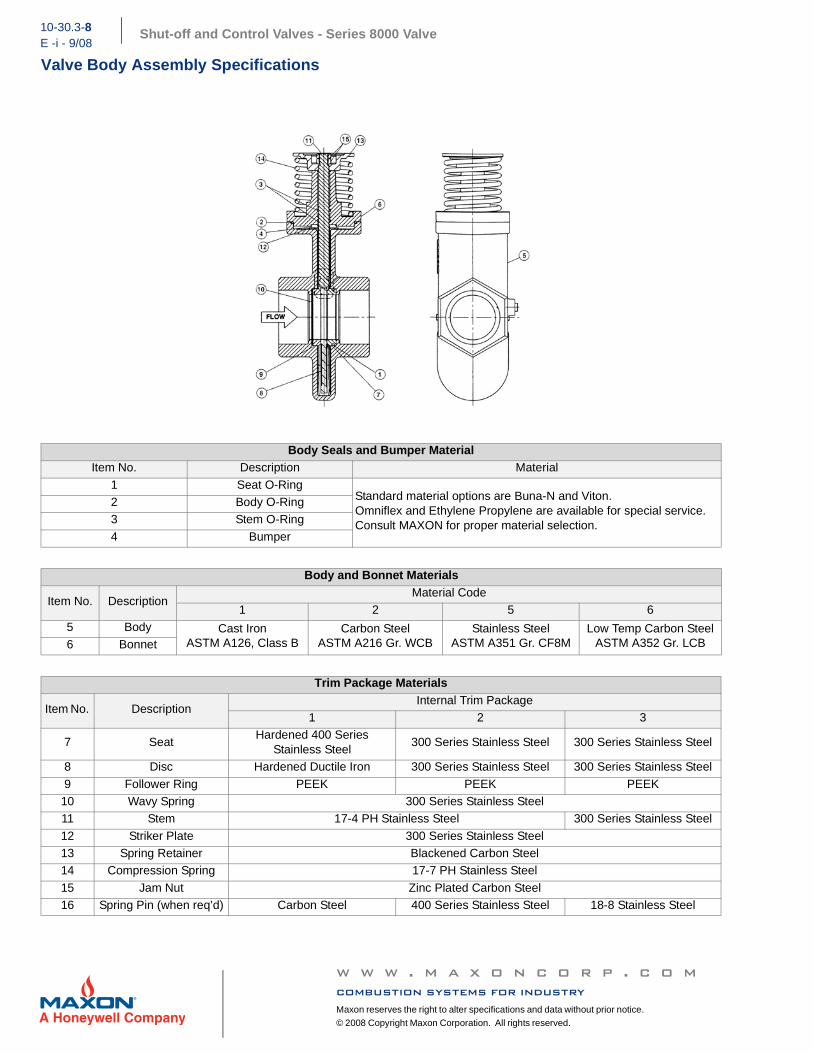
Valve Body Assembly Specifications
Body Seals and Bumper MaterialItem No. Description Material
1 Seat O-RingStandard material options are Buna-N and Viton.Omniflex and Ethylene Propylene are available for special service.Consult MAXON for proper material selection.
2 Body O-Ring3 Stem O-Ring
4 Bumper
Body and Bonnet Materials
Item No. DescriptionMaterial Code
1 2 5 65 Body Cast Iron
ASTM A126, Class B Carbon Steel
ASTM A216 Gr. WCBStainless Steel
ASTM A351 Gr. CF8MLow Temp Carbon Steel
ASTM A352 Gr. LCB6 Bonnet
Trim Package Materials
Item No. DescriptionInternal Trim Package
1 2 3
7 SeatHardened 400 Series
Stainless Steel300 Series Stainless Steel 300 Series Stainless Steel
8 Disc Hardened Ductile Iron 300 Series Stainless Steel 300 Series Stainless Steel
9 Follower Ring PEEK PEEK PEEK10 Wavy Spring 300 Series Stainless Steel11 Stem 17-4 PH Stainless Steel 300 Series Stainless Steel
12 Striker Plate 300 Series Stainless Steel13 Spring Retainer Blackened Carbon Steel14 Compression Spring 17-7 PH Stainless Steel
15 Jam Nut Zinc Plated Carbon Steel16 Spring Pin (when req’d) Carbon Steel 400 Series Stainless Steel 18-8 Stainless Steel
w w w . m a x o n c o r p . c o mcombustion systems for industryMaxon reserves the right to alter specifications and data without prior notice.
© 2008 Copyright Maxon Corporation. All rights reserved.
Shut-off and Control Valves - Series 8000 Valve 10- 30.3 - 9E - i - 9/08
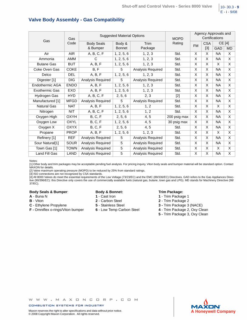
Valve Body Assembly - Gas Compatibility
GasGas
Code
Suggested Material OptionsMOPDRating
Agency Approvals and Certifications
Body Seals& Bumper
Body &Bonnet
Trim Package
FMCSA [3]
CE [4]GAD MD
Air AIR A, B, C, F 1, 2, 5, 6 1, 2, 3 Std. X X NA XAmmonia AMM C 1, 2, 5, 6 1, 2, 3 Std. X X NA X
Butane Gas BUT A, B, F 1, 2, 5, 6 1, 2, 3 Std. X X X X
Coke Oven Gas COKE B, F 5 Analysis Required Std. X X NA XDelco DEL A, B, F 1, 2, 5, 6 1, 2, 3 Std. X X NA X
Digester [1] DIG Analysis Required 5 Analysis Required Std. X X NA X
Endothermic AGA ENDO A, B, F 1, 2, 5, 6 1, 2, 3 Std. X X NA XExothermic Gas EXO A, B, F 1, 2, 5, 6 1, 2, 3 Std. X X NA X
Hydrogen Gas HYD A, B, C, F 2, 5, 6 2, 3 [2] X X NA XManufactured [1] MFGD Analysis Required 5 Analysis Required Std. X X NA X
Natural Gas NAT A, B, F 1, 2, 5, 6 1, 2 Std. X X X X
Nitrogen NIT A, B, C, F 1, 2, 5, 6 1, 2 Std. X X NA XOxygen High OXYH B, C, F 2, 5, 6 4, 5 200 psig max X X NA XOxygen Low OXYL B, C, F 1, 2, 5, 6 4, 5 30 psig max X X NA X
Oxygen X OXYX B, C, F 2, 5, 6 4, 5 Std. X X NA XPropane PROP A, B, F 1, 2, 5, 6 1, 2, 3 Std. X X X X
Refinery [1] REF Analysis Required 5 Analysis Required Std. X X NA X
Sour Natural[1] SOUR Analysis Required 5 Analysis Required Std. X X NA XTown Gas [1] TOWN Analysis Required 5 Analysis Required Std. X X X XLand Fill Gas LAND Analysis Required 5 Analysis Required Std. X X NA X
Notes:[1] Other body and trim packages may be acceptable pending fuel analysis. For pricing inquiry, Viton body seals and bumper material will be standard option. Contact MAXON for details.[2] Valve maximum operating pressure (MOPD) to be reduced by 25% from standard ratings.[3] ISO connections are not recognized by CSA standards.[4] All 8000 Valves do meet the essential requirements of the Low Voltage (73/23/EC) and the EMC (89/336/EC) Directives. GAD refers to the Gas Appliances Direc-tive (90/396/EC): this Directive only covers the use of commercially available fuels (natural gas, butane, town gas and LPG). MD stands for Machinery Directive (98/37/EC).
Body Seals & Bumper:A - Buna NB - VitonC - Ethylene PropyleneF - Omniflex o-rings/Viton bumper
Body & Bonnet:1 - Cast Iron2 - Carbon Steel5 - Stainless Steel6 - Low Temp Carbon Steel
Trim Package:1 - Trim Package 12 - Trim Package 23 - Trim Package 3 (NACE)4 - Trim Package 2, Oxy Clean5 - Trim Package 3, Oxy Clean
w w w . m a x o n c o r p . c o mcombustion systems for industry
Maxon reserves the right to alter specifications and data without prior notice. © 2008 Copyright Maxon Corporation. All rights reserved.
Shut-off and Control Valves - Series 8000 Valve10-30.3-10E -i - 9/08
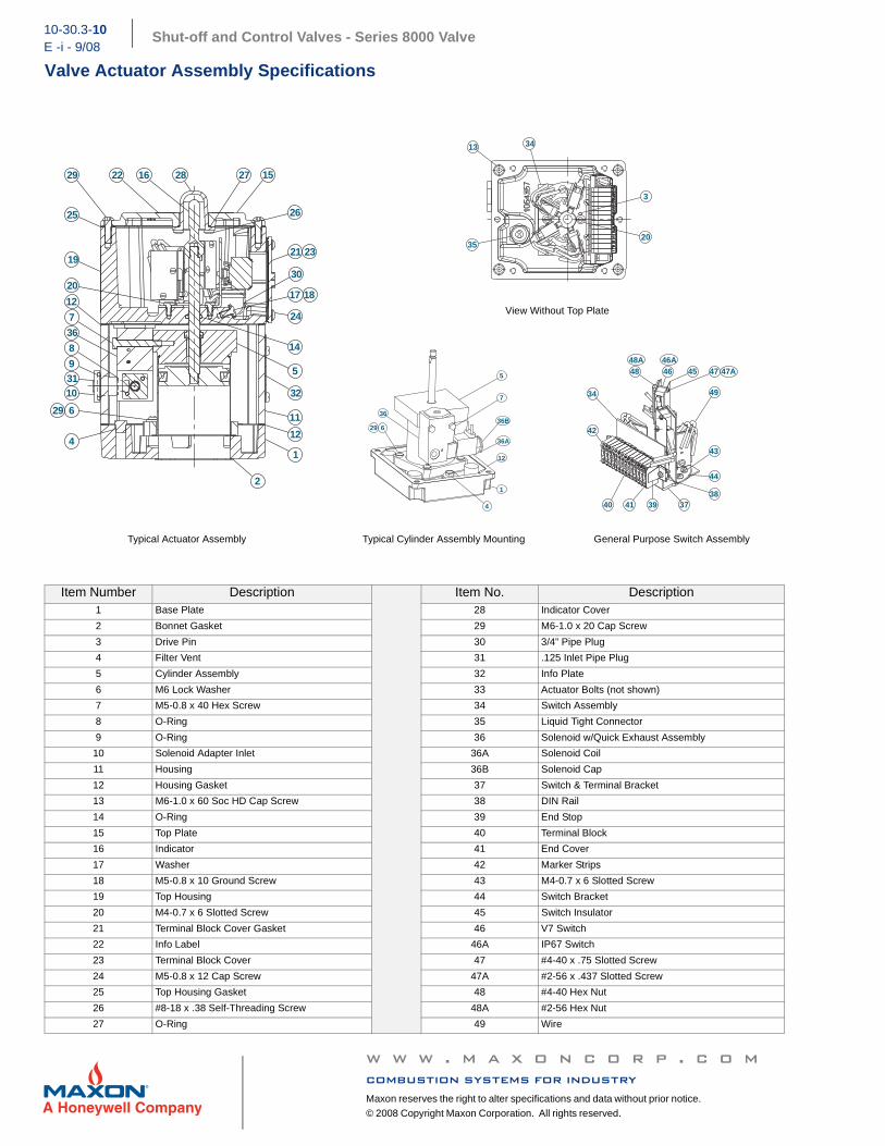
Valve Actuator Assembly Specifications
View Without Top Plate
Typical Actuator Assembly Typical Cylinder Assembly Mounting General Purpose Switch Assembly
Item Number Description Item No. Description1 Base Plate 28 Indicator Cover
2 Bonnet Gasket 29 M6-1.0 x 20 Cap Screw
3 Drive Pin 30 3/4” Pipe Plug
4 Filter Vent 31 .125 Inlet Pipe Plug
5 Cylinder Assembly 32 Info Plate
6 M6 Lock Washer 33 Actuator Bolts (not shown)
7 M5-0.8 x 40 Hex Screw 34 Switch Assembly
8 O-Ring 35 Liquid Tight Connector
9 O-Ring 36 Solenoid w/Quick Exhaust Assembly
10 Solenoid Adapter Inlet 36A Solenoid Coil
11 Housing 36B Solenoid Cap
12 Housing Gasket 37 Switch & Terminal Bracket
13 M6-1.0 x 60 Soc HD Cap Screw 38 DIN Rail
14 O-Ring 39 End Stop
15 Top Plate 40 Terminal Block
16 Indicator 41 End Cover
17 Washer 42 Marker Strips
18 M5-0.8 x 10 Ground Screw 43 M4-0.7 x 6 Slotted Screw
19 Top Housing 44 Switch Bracket
20 M4-0.7 x 6 Slotted Screw 45 Switch Insulator
21 Terminal Block Cover Gasket 46 V7 Switch
22 Info Label 46A IP67 Switch
23 Terminal Block Cover 47 #4-40 x .75 Slotted Screw
24 M5-0.8 x 12 Cap Screw 47A #2-56 x .437 Slotted Screw
25 Top Housing Gasket 48 #4-40 Hex Nut
26 #8-18 x .38 Self-Threading Screw 48A #2-56 Hex Nut
27 O-Ring 49 Wire
19
20
7
9
10
8
629
4
2
1
5
14
17 18
26
2716 282229
21 23
24
11
12
31
12
25
36
15
30
32
35
13
20
34
3
629
1
4
36B
5
7
12
36A
36
48 46 45 47
49
43
34
44
3837394140
42
46A47A
48A
w w w . m a x o n c o r p . c o mcombustion systems for industryMaxon reserves the right to alter specifications and data without prior notice.
© 2008 Copyright Maxon Corporation. All rights reserved.
Shut-off and Control Valves - Series 8000 Valve 10- 30.3 - 11
E - i - 9/08Electrical Data
General
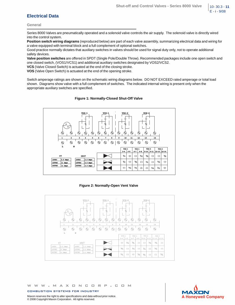
Series 8000 Valves are pneumatically operated and a solenoid valve controls the air supply. The solenoid valve is directly wired into the control system. Position switch wiring diagrams (reproduced below) are part of each valve assembly, summarizing electrical data and wiring for a valve equipped with terminal block and a full complement of optional switches. Good practice normally dictates that auxiliary switches in valves should be used for signal duty only, not to operate additional safety devices. Valve position switches are offered in SPDT (Single Pole/Double Throw). Recommended packages include one open switch and one closed switch, (VOS1/VCS1) and additional auxiliary switches designated by VOS2/VCS2.VCS (Valve Closed Switch) is actuated at the end of the closing stroke. VOS (Valve Open Switch) is actuated at the end of the opening stroke.
Switch amperage ratings are shown on the schematic wiring diagrams below. DO NOT EXCEED rated amperage or total load shown. Diagrams show valve with a full complement of switches. The indicated internal wiring is present only when the appropriate auxiliary switches are specified.
Figure 1: Normally-Closed Shut-Off Valve
Figure 2: Normally-Open Vent Valve
1 2 3 4 5 6 7 8 9 10 11 12 13 141 2 3 4 5 6 7 8 9 10 11 12 13 14
VOS-1 VCS-1 VOS-2 VCS-2VOS-1 VCS-1 VOS-2 VCS-2
IP67IP67
VOS-1VOS-1 VCS-1VCS-1 VOS-2VOS-2 VCS-2VCS-2
3-43-4 3-53-5 6-76-7 6-86-8 9-109-10 9-119-11 12-1312-13 12-1412-14
24VDC24VDC 2.0 Amps2.0 Amps
120VAC120VAC
240VAC240VAC
2.0 Amps2.0 Amps
2.0 Amps2.0 Amps
24VDC24VDC 0.5 Amps0.5 Amps
120VAC120VAC
240VAC240VAC
11 Amps11 Amps
11 Amps11 Amps
L NL N
V7V7
1 2 3 4 5 6 7 8 9 10 11 12 13 14
VCS-1 VOS-1 VCS-2 VOS-2
L N
IP67
VCS-1 VOS-1 VCS-2 VOS-2
3-4 3-5 6-7 6-8 9-10 9-11 12-13 12-14
24VDC 2.0 Amps
120VAC
240VAC
2.0 Amps
2.0 Amps
24VDC 0.5 Amps
120VAC
240VAC
11 Amps
11 Amps
V7
w w w . m a x o n c o r p . c o mcombustion systems for industry
Maxon reserves the right to alter specifications and data without prior notice. © 2008 Copyright Maxon Corporation. All rights reserved.
Shut-off and Control Valves - Series 8000 Valve10-30.3-12E -i - 9/08
Electrical Data
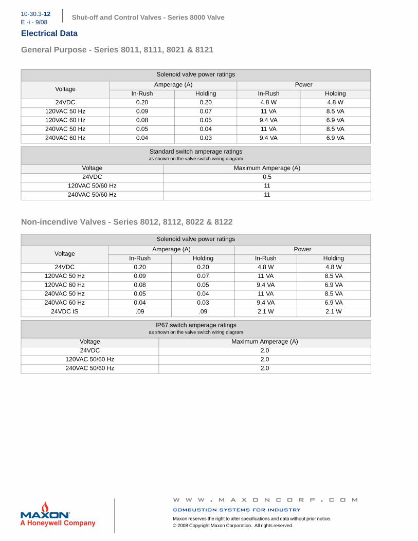
General Purpose - Series 8011, 8111, 8021 & 8121
Non-incendive Valves - Series 8012, 8112, 8022 & 8122
Solenoid valve power ratings
VoltageAmperage (A) Power
In-Rush Holding In-Rush Holding24VDC 0.20 0.20 4.8 W 4.8 W
120VAC 50 Hz 0.09 0.07 11 VA 8.5 VA120VAC 60 Hz 0.08 0.05 9.4 VA 6.9 VA240VAC 50 Hz 0.05 0.04 11 VA 8.5 VA
240VAC 60 Hz 0.04 0.03 9.4 VA 6.9 VA
Standard switch amperage ratingsas shown on the valve switch wiring diagram
Voltage Maximum Amperage (A)24VDC 0.5
120VAC 50/60 Hz 11
240VAC 50/60 Hz 11
Solenoid valve power ratings
VoltageAmperage (A) Power
In-Rush Holding In-Rush Holding24VDC 0.20 0.20 4.8 W 4.8 W
120VAC 50 Hz 0.09 0.07 11 VA 8.5 VA
120VAC 60 Hz 0.08 0.05 9.4 VA 6.9 VA240VAC 50 Hz 0.05 0.04 11 VA 8.5 VA240VAC 60 Hz 0.04 0.03 9.4 VA 6.9 VA
24VDC IS .09 .09 2.1 W 2.1 W
IP67 switch amperage ratingsas shown on the valve switch wiring diagram
Voltage Maximum Amperage (A)
24VDC 2.0120VAC 50/60 Hz 2.0240VAC 50/60 Hz 2.0
w w w . m a x o n c o r p . c o mcombustion systems for industryMaxon reserves the right to alter specifications and data without prior notice.
© 2008 Copyright Maxon Corporation. All rights reserved.
Shut-off and Control Valves - Series 8000 Valve 10- 30.3 - 13E - i - 9/08
Intrinsically Safe Valves - Series 8033 & 8133
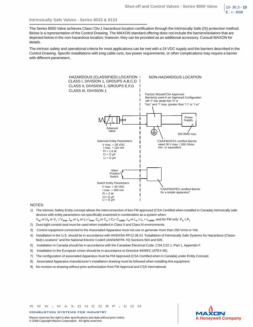
The Series 8000 Valve achieves Class I Div.1 hazardous location certification through the Intrinsically Safe (IS) protection method. Below is a representation of the Control Drawing. The MAXON standard offering does not include the barriers/isolators that are depicted below in the non-hazardous location; however, they can be provided as an additional accessory. Consult MAXON for details.
The intrinsic safety and operational criteria for most applications can be met with a 24 VDC supply and the barriers described in the Control Drawing. Specific installations with long cable runs, low power requirements, or other complications may require a barrier with different parameters.
NOTES:1) The Intrinsic Safety Entity concept allows the interconnection of two FM approved (CSA Certified when installed in Canada) Intrinsically safe
devices with entity parameters not specifically examined in combination as a system when:Voc or Uo or Vt ≤ Vmax, Isc or Io or It ≤ Imax, Ca or Co ≥ Ci+ Ccable, La or Lo ≥ Li + Lcable, and for FM only: Po ≤ Pi.
2) Dust-tight conduit seal must be used when installed in Class II and Class III environments.
3) Control equipment connected to the Associated Apparatus must not use or generate more than 250 Vrms or Vdc.
4) Installation in the U.S. should be in accordance with ANSI/ISA RP12.06.01 “Installation of Intrinsically Safe Systems for Hazardous (Classi-fied) Locations” and the National Electric Code® (ANSI/NFPA 70) Sections 504 and 505.
5) Installation in Canada should be in accordance with the Canadian Electrical Code, CSA C22.1, Part 1, Appendix F.
6) Installation in the European Union should be in accordance to Directive 94/9/EC (ATEX 95).
7) The configuration of associated Apparatus must be FM Approved (CSA Certified when in Canada) under Entity Concept.
8) Associated Apparatus manufacturer’s installation drawing must be followed when installing this equipment.
9) No revision to drawing without prior authorization from FM Approval and CSA International.
HAZARDOUS (CLASSIFIED) LOCATIONCLASS I, DIVISION 1, GROUPS A,B,C,DCLASS II, DIVISION 1, GROUPS E,F,GCLASS III, DIVISION 1
NON-HAZARDOUS LOCATION
Factory Mutual/CSA ApprovedBarrier(s) used in an Approved Configuratonwith “V” max. greater than “VI” or
“Voc” and “I” max. greater than “I t” or “I sc”
PowerSupply
250 RMS max.
CSA/FM/ATEX certified Barrier
min. or equivalentrated 28 V max. / 300 Ohms
“CSA/FM/ATEX certified Barrierfor a simple apparatus”
SolenoidValve
Solenoid Entity ParametersV max. = 28 VDCI max. = 115 mAPi = 1.6 WCi = O µFLi = O µH
ValvePositionSwitch
Switch Entity ParametersV max. = 30 VDCI max. = 500 mAPi = 2 WCi= O µFLi = O µH
w w w . m a x o n c o r p . c o mcombustion systems for industry
Maxon reserves the right to alter specifications and data without prior notice. © 2008 Copyright Maxon Corporation. All rights reserved.
Shut-off and Control Valves - Series 8000 Valve10-30.3-14E -i - 9/08
To select a different safety barrier, choose a design that limits voltage, current, and power under worst-case fault conditions to values less than the IS entity parameters, while still meeting the minimum operational requirements under worst-case non-fault conditions. The IS entity parameters and operational requirements are listed in the following tables.
The barrier will specify a maximum voltage peak Voc 1, a maximum short-circuit current, Isc
2 and maximum power output Po 3. These barrier ratings must be less than or equal to the IS entity parameters of the field device, i.e., Voc ≤ Vmax, Isc ≤ Imax, and Po ≤ Pi.The barrier will also specify a maximum allowed capacitance Ca and inductance La, which must be greater than or equal to the sum of those of the load device and field wiring, i.e., Ca ≥ Ci + Ccable and La ≥ Li + Lcable.
The solenoid requires a minimum current (Imin) to operate properly. The nominal barrier input voltage (Vworking, as specified by the barrier) must be adequate to provide Imin through the maximum barrier resistance, the maximum wiring resistance, the resistance of any fuses, and the maximum solenoid resistance (Ri).
NOTE: Vworking will always be less than Vmax or Voc. Never intentionally supply Voc to the barrier, as this could blow an internal fuse and ruin the barrier.
w w w . m a x o n c o r p . c o mcombustion systems for industryMaxon reserves the right to alter specifications and data without prior notice.
© 2008 Copyright Maxon Corporation. All rights reserved.
Shut-off and Control Valves - Series 8000 Valve 10- 30.3 - 15E - i - 9/08
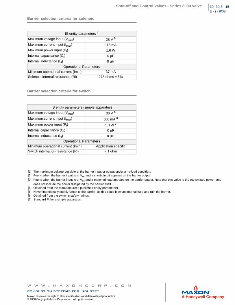
Barrier selection criteria for solenoid
Barrier selection criteria for switch
IS entity parameters 4
Maximum voltage input (Vmax) 28 V 5
Maximum current input (Imax) 115 mA
Maximum power input (Pi) 1.6 W
Internal capacitance (Ci) 0 µF
Internal inductance (Li) 0 µH
Operational Parameters
Minimum operational current (Imin) 37 mASolenoid internal resistance (Ri) 275 ohms ± 8%
IS entity parameters (simple apparatus)
Maximum voltage input (Vmax) 30 V 6
Maximum current input (Imax) 500 mA 6
Maximum power input (Pi) 1.3 W 7
Internal capacitance (Ci) 0 µF
Internal inductance (Li) 0 µH
Operational ParametersMinimum operational current (Imin) Application specific
Switch internal on-resistance (Ri) < 1 ohm
[1] The maximum voltage possible at the barrier input or output under a no-load condition.[2] Found when the barrier input is at Voc and a short-circuit appears on the barrier output.[3] Found when the barrier input is at Voc and a matched load appears on the barrier output. Note that this value is the transmitted power, and
does not include the power dissipated by the barrier itself.[4] Obtained from the manufacturer’s published entity parameters.[5] Never intentionally supply Vmax to the barrier, as this could blow an internal fuse and ruin the barrier.[6] Obtained from the switch’s safety ratings.[7] Standard Pi for a simple apparatus.
w w w . m a x o n c o r p . c o mcombustion systems for industry
Maxon reserves the right to alter specifications and data without prior notice. © 2008 Copyright Maxon Corporation. All rights reserved.
Shut-off and Control Valves - Series 8000 Valve10-30.3-16
E -i - 9/08Dimensions & Weights
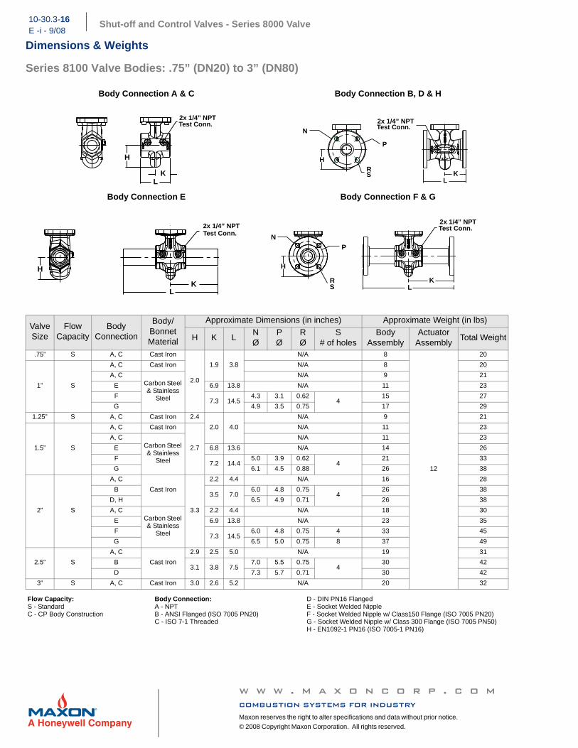
Series 8100 Valve Bodies: .75” (DN20) to 3” (DN80)
Body Connection A & C Body Connection B, D & H
Body Connection E Body Connection F & G
Valve Size
FlowCapacity
BodyConnection
Body/BonnetMaterial
Approximate Dimensions (in inches) Approximate Weight (in lbs)
H K LNØ
PØ
RØ
S# of holes
BodyAssembly
ActuatorAssembly
Total Weight
.75” S A, C Cast Iron
2.0
1.9 3.8
N/A 8
12
20
1” S
A, C Cast Iron N/A 8 20
A, CCarbon Steel & Stainless
Steel
N/A 9 21
E 6.9 13.8 N/A 11 23
F7.3 14.5
4.3 3.1 0.62 4
15 27
G 4.9 3.5 0.75 17 29
1.25” S A, C Cast Iron 2.4
2.0 4.0
N/A 9 21
1.5” S
A, C Cast Iron
2.7
N/A 11 23
A, CCarbon Steel & Stainless
Steel
N/A 11 23
E 6.8 13.6 N/A 14 26
F7.2 14.4
5.0 3.9 0.62 4
21 33
G 6.1 4.5 0.88 26 38
2” S
A, C
Cast Iron
3.3
2.2 4.4 N/A 16 28
B3.5 7.0
6.0 4.8 0.75 4
26 38
D, H 6.5 4.9 0.71 26 38
A, CCarbon Steel & Stainless
Steel
2.2 4.4 N/A 18 30
E 6.9 13.8 N/A 23 35
F7.3 14.5
6.0 4.8 0.75 4 33 45
G 6.5 5.0 0.75 8 37 49
2.5” S
A, C
Cast Iron
2.9 2.5 5.0 N/A 19 31
B3.1 3.8 7.5
7.0 5.5 0.75 4
30 42
D 7.3 5.7 0.71 30 42
3” S A, C Cast Iron 3.0 2.6 5.2 N/A 20 32
Flow Capacity:S - StandardC - CP Body Construction
Body Connection:A - NPTB - ANSI Flanged (ISO 7005 PN20)C - ISO 7-1 Threaded
D - DIN PN16 FlangedE - Socket Welded NippleF - Socket Welded Nipple w/ Class150 Flange (ISO 7005 PN20)G - Socket Welded Nipple w/ Class 300 Flange (ISO 7005 PN50)H - EN1092-1 PN16 (ISO 7005-1 PN16)
L K
H
2x 1/4” NPTTest Conn.
R S
N
H
K L
P
2x 1/4” NPTTest Conn.
L K
H
2x 1/4” NPTTest Conn.
R S L
N
K
H
P
2x 1/4” NPTTest Conn.
w w w . m a x o n c o r p . c o mcombustion systems for industryMaxon reserves the right to alter specifications and data without prior notice.
© 2008 Copyright Maxon Corporation. All rights reserved.
Shut-off and Control Valves - Series 8000 Valve 10- 30.3 - 17E - i - 9/08
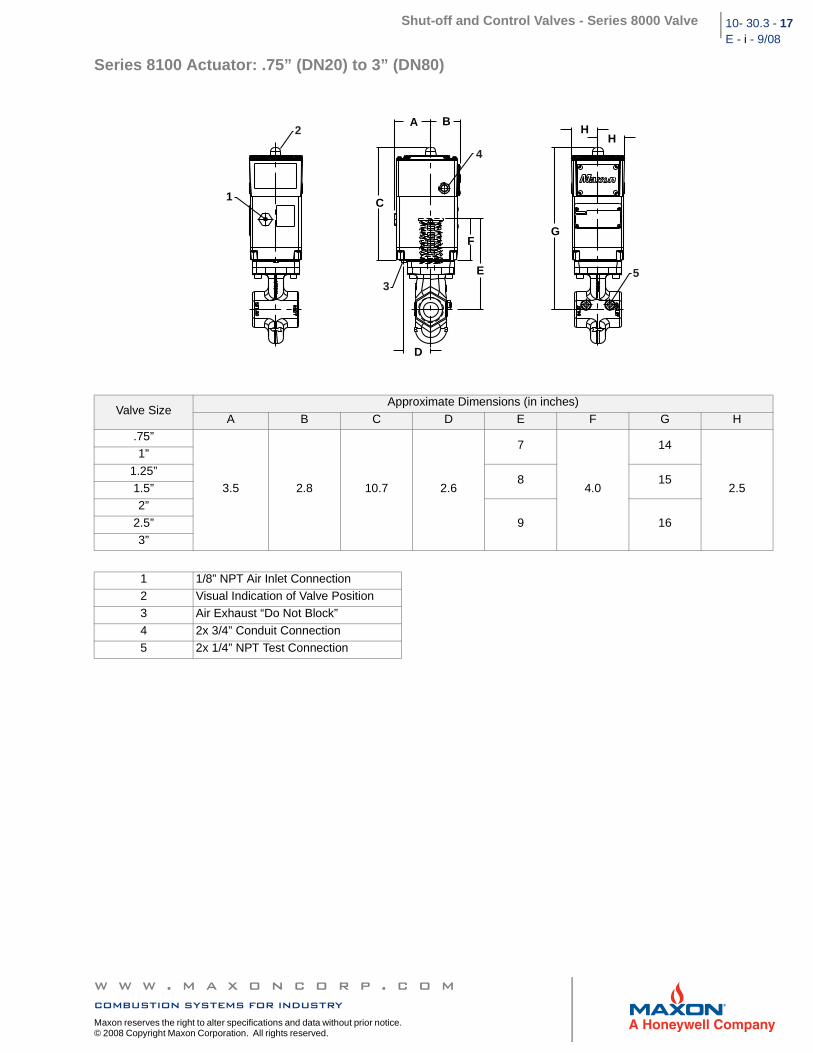
Series 8100 Actuator: .75” (DN20) to 3” (DN80)
Valve SizeApproximate Dimensions (in inches)
A B C D E F G H.75”
3.5 2.8 10.7 2.6
7
4.0
14
2.5
1”
1.25”8 15
1.5”2”
9 16 2.5”3”
1 1/8” NPT Air Inlet Connection2 Visual Indication of Valve Position3 Air Exhaust “Do Not Block”
4 2x 3/4” Conduit Connection5 2x 1/4” NPT Test Connection
1
G
HH
E
A B
C
F
D
2
3
4
5
w w w . m a x o n c o r p . c o mcombustion systems for industry
Maxon reserves the right to alter specifications and data without prior notice. © 2008 Copyright Maxon Corporation. All rights reserved.
Shut-off and Control Valves - Series 8000 Valve10-30.3-18E -i - 9/08
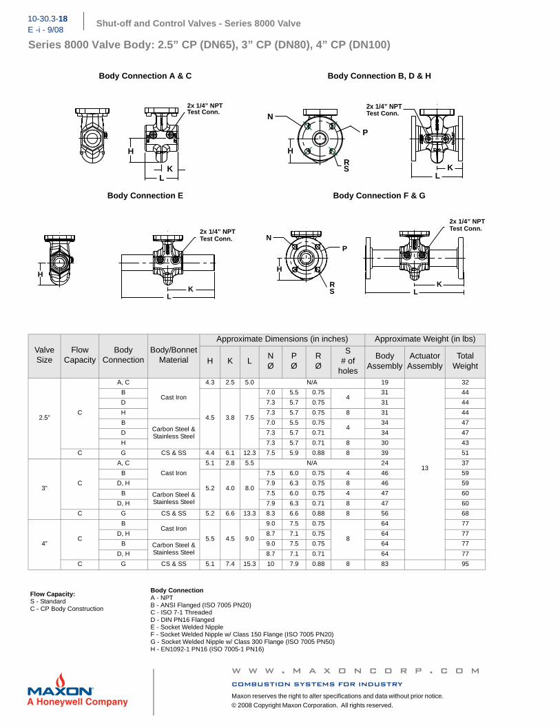
Series 8000 Valve Body: 2.5” CP (DN65), 3” CP (DN80), 4” CP (DN100)
Body Connection A & C Body Connection B, D & H
Body Connection E Body Connection F & G
ValveSize
FlowCapacity
BodyConnection
Body/BonnetMaterial
Approximate Dimensions (in inches) Approximate Weight (in lbs)
H K LNØ
PØ
RØ
S# of
holes
BodyAssembly
ActuatorAssembly
Total Weight
2.5”C
A, C
Cast Iron
4.3 2.5 5.0 N/A 19
13
32
B
4.5 3.8 7.5
7.0 5.5 0.75 4
31 44
D 7.3 5.7 0.75 31 44
H 7.3 5.7 0.75 8 31 44
BCarbon Steel & Stainless Steel
7.0 5.5 0.75 4
34 47
D 7.3 5.7 0.71 34 47
H 7.3 5.7 0.71 8 30 43
C G CS & SS 4.4 6.1 12.3 7.5 5.9 0.88 8 39 51
3”C
A, C
Cast Iron
5.1 2.8 5.5 N/A 24 37
B
5.2 4.0 8.0
7.5 6.0 0.75 4 46 59
D, H 7.9 6.3 0.75 8 46 59
B Carbon Steel & Stainless Steel
7.5 6.0 0.75 4 47 60
D, H 7.9 6.3 0.71 8 47 60
C G CS & SS 5.2 6.6 13.3 8.3 6.6 0.88 8 56 68
4”C
BCast Iron
5.5 4.5 9.0
9.0 7.5 0.75
8
64 77
D, H 8.7 7.1 0.75 64 77
B Carbon Steel & Stainless Steel
9.0 7.5 0.75 64 77
D, H 8.7 7.1 0.71 64 77
C G CS & SS 5.1 7.4 15.3 10 7.9 0.88 8 83 95
Flow Capacity:S - StandardC - CP Body Construction
Body ConnectionA - NPTB - ANSI Flanged (ISO 7005 PN20)C - ISO 7-1 ThreadedD - DIN PN16 FlangedE - Socket Welded NippleF - Socket Welded Nipple w/ Class 150 Flange (ISO 7005 PN20)G - Socket Welded Nipple w/ Class 300 Flange (ISO 7005 PN50)H - EN1092-1 PN16 (ISO 7005-1 PN16)
L K
H
2x 1/4” NPTTest Conn.
R S
N
H
K L
P
2x 1/4” NPTTest Conn.
L K
H
2x 1/4” NPTTest Conn.
R S L
N
K
H
P
2x 1/4” NPTTest Conn.
w w w . m a x o n c o r p . c o mcombustion systems for industryMaxon reserves the right to alter specifications and data without prior notice.
© 2008 Copyright Maxon Corporation. All rights reserved.
Shut-off and Control Valves - Series 8000 Valve 10- 30.3 - 19E - i - 9/08
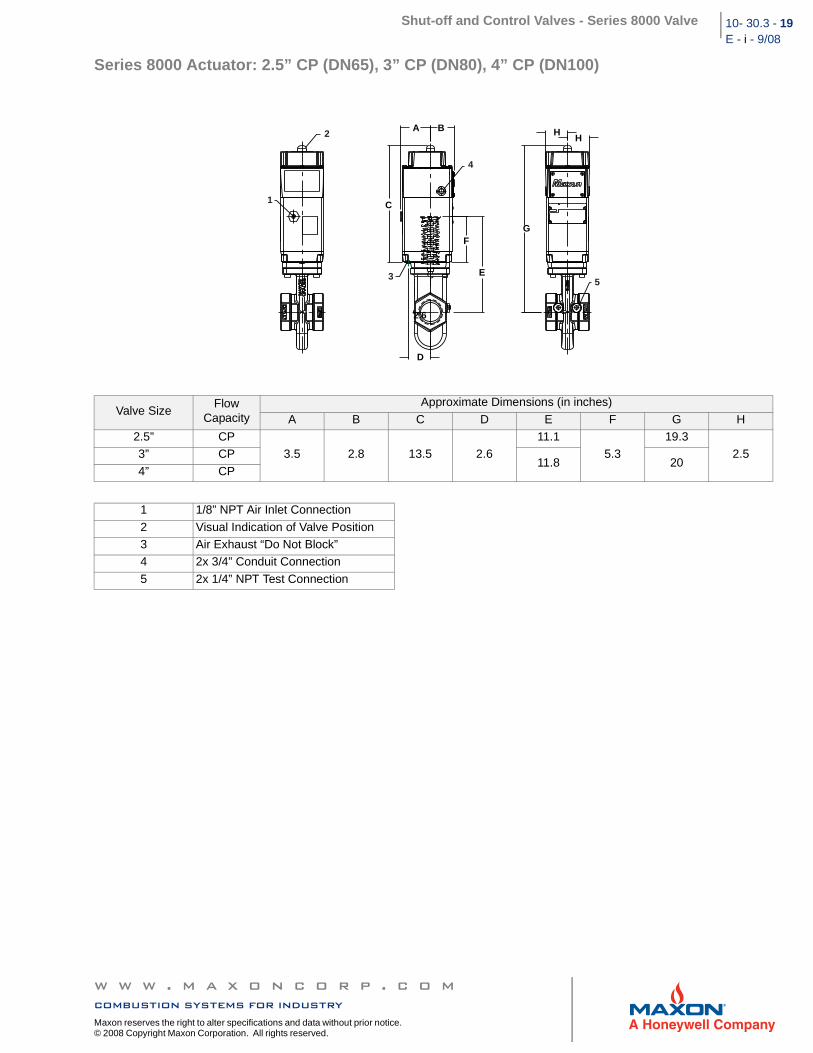
Series 8000 Actuator: 2.5” CP (DN65), 3” CP (DN80), 4” CP (DN100)
Valve SizeFlow
CapacityApproximate Dimensions (in inches)
A B C D E F G H2.5” CP
3.5 2.8 13.5 2.6 11.1
5.3 19.3
2.5 3” CP11.8 20
4” CP
1 1/8” NPT Air Inlet Connection
2 Visual Indication of Valve Position3 Air Exhaust “Do Not Block”4 2x 3/4” Conduit Connection
5 2x 1/4” NPT Test Connection
G
HH
E
A B
C
F
2.6
D
1
2
3
4
5
w w w . m a x o n c o r p . c o mcombustion systems for industry
Maxon reserves the right to alter specifications and data without prior notice. © 2008 Copyright Maxon Corporation. All rights reserved.
Shut-off and Control Valves - Series 8000 Valve10-30.3-20E -i - 9/08
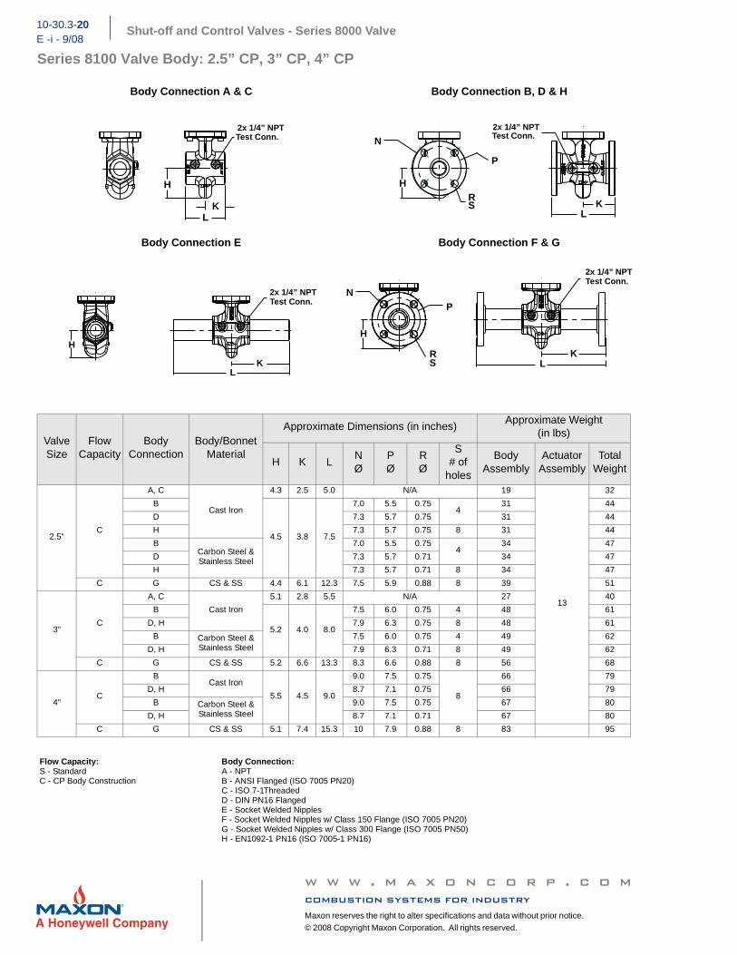
Series 8100 Valve Body: 2.5” CP, 3” CP, 4” CP
Body Connection A & C Body Connection B, D & H
Body Connection E Body Connection F & G
Valve Size
FlowCapacity
BodyConnection
Body/BonnetMaterial
Approximate Dimensions (in inches) Approximate Weight
(in lbs)
H K LNØ
PØ
RØ
S# of
holes
BodyAssembly
ActuatorAssembly
TotalWeight
2.5”C
A, C
Cast Iron
4.3 2.5 5.0 N/A 19
13
32
B
4.5 3.8 7.5
7.0 5.5 0.75 4
31 44
D 7.3 5.7 0.75 31 44
H 7.3 5.7 0.75 8 31 44
BCarbon Steel & Stainless Steel
7.0 5.5 0.75 4
34 47
D 7.3 5.7 0.71 34 47
H 7.3 5.7 0.71 8 34 47
C G CS & SS 4.4 6.1 12.3 7.5 5.9 0.88 8 39 51
3”C
A, C
Cast Iron
5.1 2.8 5.5 N/A 27 40
B
5.2 4.0 8.0
7.5 6.0 0.75 4 48 61
D, H 7.9 6.3 0.75 8 48 61
B Carbon Steel & Stainless Steel
7.5 6.0 0.75 4 49 62
D, H 7.9 6.3 0.71 8 49 62
C G CS & SS 5.2 6.6 13.3 8.3 6.6 0.88 8 56 68
4”C
BCast Iron
5.5 4.5 9.0
9.0 7.5 0.75
8
66 79
D, H 8.7 7.1 0.75 66 79
B Carbon Steel & Stainless Steel
9.0 7.5 0.75 67 80
D, H 8.7 7.1 0.71 67 80
C G CS & SS 5.1 7.4 15.3 10 7.9 0.88 8 83 95
Flow Capacity:S - StandardC - CP Body Construction
Body Connection:A - NPTB - ANSI Flanged (ISO 7005 PN20)C - ISO 7-1ThreadedD - DIN PN16 FlangedE - Socket Welded NipplesF - Socket Welded Nipples w/ Class 150 Flange (ISO 7005 PN20)G - Socket Welded Nipples w/ Class 300 Flange (ISO 7005 PN50)H - EN1092-1 PN16 (ISO 7005-1 PN16)
L K
H
2x 1/4” NPTTest Conn.
R S
N
H
K L
P
2x 1/4” NPTTest Conn.
L K
H
2x 1/4” NPTTest Conn.
R S L
N
K
H
P
2x 1/4” NPTTest Conn.
w w w . m a x o n c o r p . c o mcombustion systems for industryMaxon reserves the right to alter specifications and data without prior notice.
© 2008 Copyright Maxon Corporation. All rights reserved.
Shut-off and Control Valves - Series 8000 Valve 10- 30.3 - 21E - i - 9/08
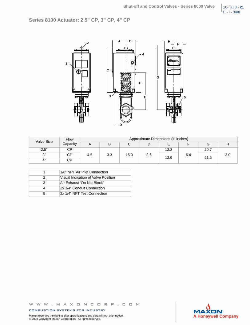
Series 8100 Actuator: 2.5” CP, 3” CP, 4” CP
Valve SizeFlow
CapacityApproximate Dimensions (in inches)
A B C D E F G H2.5” CP
4.5 3.3 15.0 3.6 12.2
6.4 20.7
3.0 3” CP12.9 21.5
4” CP
1 1/8” NPT Air Inlet Connection
2 Visual Indication of Valve Position3 Air Exhaust “Do Not Block”4 2x 3/4” Conduit Connection
5 2x 1/4” NPT Test Connection
G
HH
E
A B
C
F
D
1
2
3
4
5
w w w . m a x o n c o r p . c o mcombustion systems for industry
Maxon reserves the right to alter specifications and data without prior notice. © 2008 Copyright Maxon Corporation. All rights reserved.
Shut-off and Control Valves - Series 8000 Valve10-30.3-22E -i - 9/08
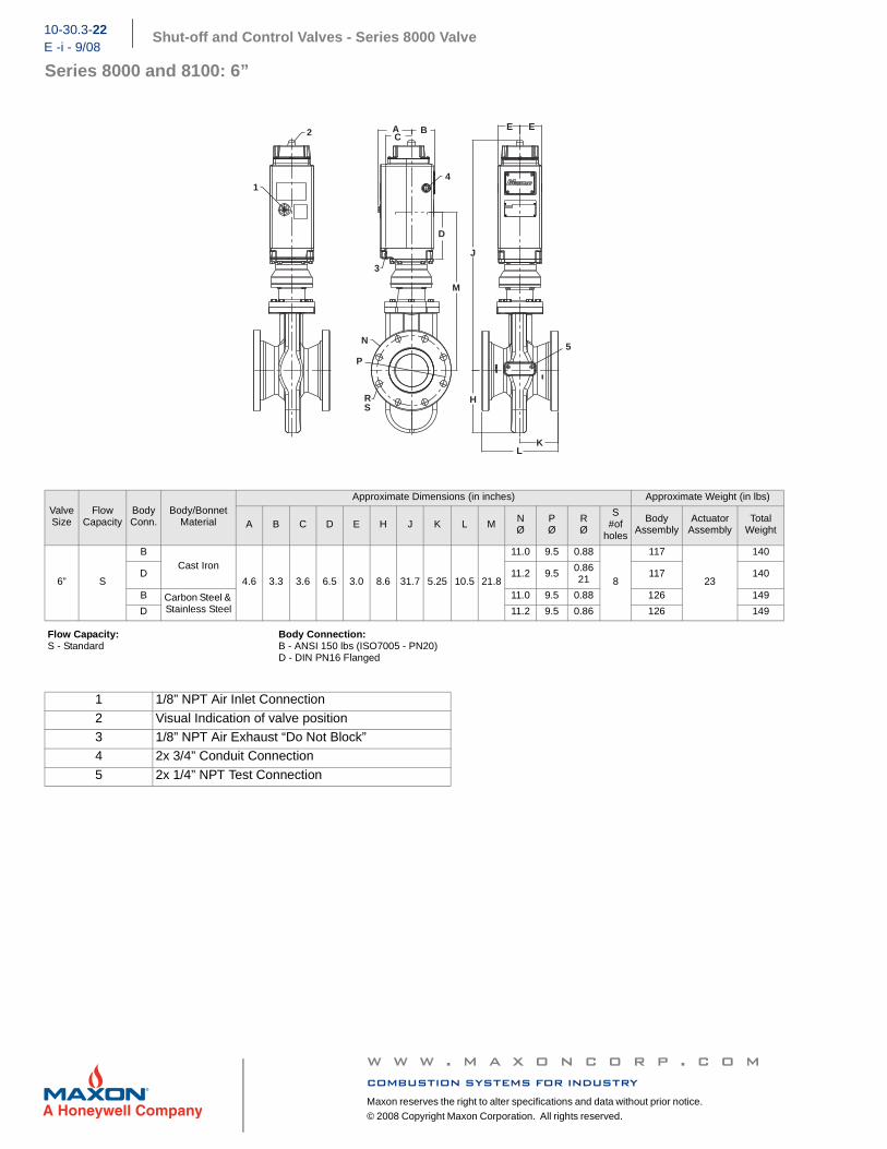
Series 8000 and 8100: 6”
Valve Size
FlowCapacity
Body Conn.
Body/BonnetMaterial
Approximate Dimensions (in inches) Approximate Weight (in lbs)
A B C D E H J K L M NØ
PØ
RØ
S#of
holes
BodyAssembly
ActuatorAssembly
TotalWeight
6” S
BCast Iron
4.6 3.3 3.6 6.5 3.0 8.6 31.7 5.25 10.5 21.8
11.0 9.5 0.88
8
117
23
140
D 11.2 9.5 0.86 21
117 140
B Carbon Steel & Stainless Steel
11.0 9.5 0.88 126 149
D 11.2 9.5 0.86 126 149
Flow Capacity:S - Standard
Body Connection:B - ANSI 150 lbs (ISO7005 - PN20)D - DIN PN16 Flanged
1 1/8” NPT Air Inlet Connection
2 Visual Indication of valve position3 1/8” NPT Air Exhaust “Do Not Block”4 2x 3/4” Conduit Connection
5 2x 1/4” NPT Test Connection
INLET
INLET
OUTLET
OUTLET
A BC
D
M
N
P
R S
H
LK
J
E E
1
2
3
4
5
w w w . m a x o n c o r p . c o mcombustion systems for industryMaxon reserves the right to alter specifications and data without prior notice.
© 2008 Copyright Maxon Corporation. All rights reserved.
Shut-off and Control Valves - Series 8000 Valve 10- 30.3 - 23E - i - 9/08
Accessories
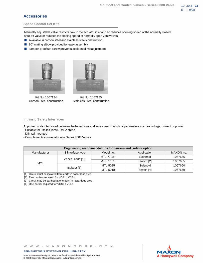
Speed Control Set Kits
Intrinsic Safety Interfaces
Approved units interposed between the hazardous and safe area circuits limit parameters such as voltage, current or power. - Suitable for use in Class I, Div. 2 areas- DIN rail mounted- Complements intrinsically safe Series 8000 Valves
Manually adjustable valve restricts flow to the actuator inlet and so reduces opening speed of the normally closed shut-off valve or reduces the closing speed of normally open vent valves.
Available in carbon steel and stainless steel construction
90° mating elbow provided for easy assemblyTamper-proof set screw prevents accidental misadjustment
Kit No. 1067124Carbon Steel construction
Kit No. 1067125Stainless Steel construction
Engineering recommendations for barriers and isolator optionManufacturer IS interface type Model no. Application MAXON no.
MTLZener Diode [1]
MTL 7728+ Solenoid 1067656
MTL 7787+ Switch [2] 1067655
Isolator [3]MTL 5025 Solenoid 1067660MTL 5018 Switch [4] 1067659
[1] Circuit must be isolated from earth in hazardous area[2] Two barriers required for VOS1 / VCS1[3] Circuit may be earthed at one point in hazardous area[4] One barrier required for VOS1 / VCS1
w w w . m a x o n c o r p . c o mcombustion systems for industry
Maxon reserves the right to alter specifications and data without prior notice. © 2008 Copyright Maxon Corporation. All rights reserved.
Shut-off and Control Valves - Series 8000 Valve10-30.3-24E -i - 9/08
w w w . m a x o n c o r p . c o mcombustion systems for industryMaxon reserves the right to alter specifications and data without prior notice.
© 2008 Copyright Maxon Corporation. All rights reserved.