Embed Size (px)
DESCRIPTION
Valve selection
Citation preview
Note: The source of the technical material in this volume is the Professional Engineering Development Program (PEDP) of Engineering Services.
Warning: The material contained in this document was developed for Saudi Aramco and is intended for the exclusive use of Saudi Aramco’s employees. Any material contained in this document which is not already in the public domain may not be copied, reproduced, sold, given, or disclosed to third parties, or otherwise used in whole, or in part, without the written permission of the Vice President, Engineering Services, Saudi Aramco.
Chapter : Mechanical For additional information on this subject, contact File Reference: MEX-101.06 PEDD Coordinator on 874-6556
Engineering Encyclopedia Saudi Aramco DeskTop Standards
VALVE SELECTION: TYPES AND CLASSES
Engineering Encyclopedia Piping, Pipelines & Valves
Valve Selection: Types and Classes
Saudi Aramco DeskTop Standards i
Section .....................................................................................................................Page
INFORMATION ............................................................................................................... 5 INTRODUCTION............................................................................................................. 5 DESCRIBING VALVES IN TERMS OF THEIR FUNCTIONS, TYPES, AND COMPONENTS............................................................................................................... 6
Gate Valves.......................................................................................................... 7 Function................................................................................................................ 7 Major Gate Valve Components............................................................................. 9 Body Pattern......................................................................................................... 9 Gates.................................................................................................................. 10 Bonnets .............................................................................................................. 11 Trim .................................................................................................................... 13 Stems ................................................................................................................. 13 Stem Packing System ........................................................................................ 15 End Connections ................................................................................................ 16 Seats .................................................................................................................. 17 Ball Valve............................................................................................................ 18 Function.............................................................................................................. 20 Major Ball Valve Types and Components........................................................... 20 Types.................................................................................................................. 20 Body ................................................................................................................... 21 Ball ..................................................................................................................... 22 Seats .................................................................................................................. 23 Ball Supports ...................................................................................................... 24 Plug Valve .......................................................................................................... 24 Function.............................................................................................................. 25 Major Plug Valve Types and Components ......................................................... 26 Types.................................................................................................................. 26 Body ................................................................................................................... 27 Plug Styles and Seating Mechanisms ................................................................ 27 Plug Support....................................................................................................... 28 Seats .................................................................................................................. 28
SELECTING THE TYPE AND SIZE OF A VALVE THAT IS SUITABLE FOR PROCESS APPLICATIONS .......................................................................................... 30
Engineering Encyclopedia Piping, Pipelines & Valves
Valve Selection: Types and Classes
Saudi Aramco DeskTop Standards ii
Step 1: List the Data Required........................................................................... 31 Valve Sizing........................................................................................................ 31 Step 2: Identify Suitable Valve-Types and Components.................................... 32 Step 3: Determine Valve-Type Limitations for Suitable Valves through Saudi Aramco Engineering Standard SAES-L-008, Selection of Valve ............ 33 Step 4: Finalize Valve Selection by Considering Other Factors......................... 39 Standardization................................................................................................... 39 Inventory............................................................................................................. 39 Experience.......................................................................................................... 39 Cost .................................................................................................................... 40 Delivery Time...................................................................................................... 40 Materials ............................................................................................................. 40 Dimensions......................................................................................................... 40 Step 5: Provide a Full Description...................................................................... 40 Sample Problem 1: Part A. ................................................................................ 45 Solution: Part A.................................................................................................. 46 Sample Problem 1: Part B ................................................................................. 48 Solution: Part B.................................................................................................. 49 Locations "A" and "B" ......................................................................................... 49 Location "C"........................................................................................................ 49 Location "D"........................................................................................................ 50 Location "D"........................................................................................................ 50 Location "E" ........................................................................................................ 50 Determining the Required Valve Class and Associated MAOP.......................... 51 Pressure/Temperature Ratings........................................................................... 56
IDENTIFYING VALVE INSPECTION AND TESTING REQUIREMENTS ..................... 57 Minimum Inspection Requirements for New Valves ........................................... 58 Surface Examination .......................................................................................... 58 Dimensional and Component Checks ................................................................ 59 Shell Test............................................................................................................ 60 Back Seat Test ................................................................................................... 60 Low-pressure Closure Test................................................................................. 61 High-pressure Closure Test................................................................................ 61 Fire safe Test...................................................................................................... 62 Other Inspection Considerations ........................................................................ 63
Engineering Encyclopedia Piping, Pipelines & Valves
Valve Selection: Types and Classes
Saudi Aramco DeskTop Standards iii
SUMMARY.................................................................................................................... 64 WORK AIDS.................................................................................................................. 65 WORK AID 1: STEPS FOR SELECTING VALVES AND VALVE COMPONENTS ...... 65
WORK AID 2: Procedure for Determining Valve Class, MAOP, and Appropriate Test Type ........................................................................................ 69
Engineering Encyclopedia Piping, Pipelines & Valves
Valve Selection: Types and Classes
Saudi Aramco DeskTop Standards iv
LIST OF FIGURES
Figure 1. Full-Port Gate Valve......................................................................................... 8
Figure 2. Solid-Wedge Gate.......................................................................................... 10
Figure 3. Flexible-Wedge Gate ..................................................................................... 11
Figure 4. Bolted Bonnet................................................................................................. 12
Figure 5. Screwed Bonnet............................................................................................. 13
Figure 6. Rising Stem with Outside Screw (OS&Y)....................................................... 14
Figure 8. Stem Packing System with Lantern Ring ....................................................... 16
Figure 9. Integral Seat................................................................................................... 18
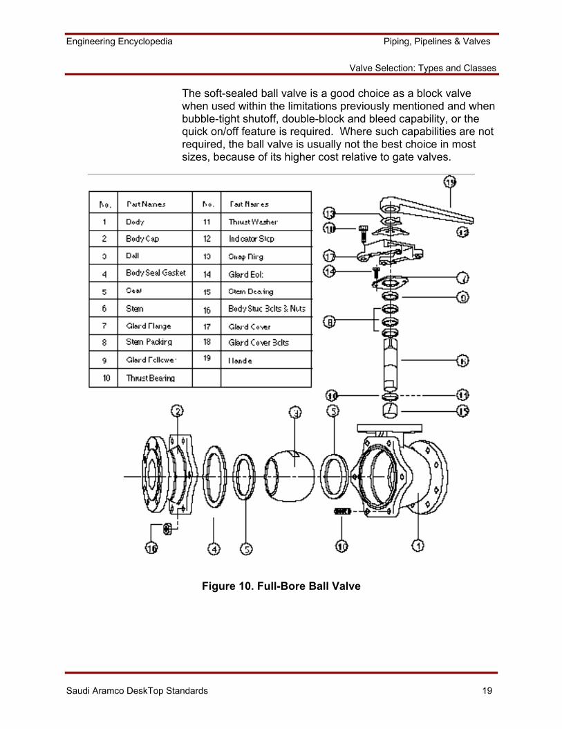
Figure 10. Full-Bore Ball Valve...................................................................................... 19
Figure 11. Seat Rings................................................................................................... 22
Figure 12. Multi-Segment Plug Valve ........................................................................... 25
Figure 13. Pump Rising System................................................................................... 45
Figure 14. List of Material Specifications...................................................................... 53
Figure 15. Typical Pressure/Temperature Limits for Gate and Ball Valves ................. 56
Figure 17. Mandatory Tests for Valve Types (Based on API 598 and 04-SAMSS-048).................................................................................... 70
LIST OF TABLES
Table 1. Information on Valve Sizes, Ratings and Standards ...................................... 43
Table 2. Standard Class Ratings for Group 1.1 Materials ............................................ 54
Table 3. Special Class, Working Pressure by Classes, psi .......................................... 54
55
Engineering Encyclopedia Piping, Pipelines & Valves
Valve Selection: Types and Classes
Saudi Aramco DeskTop Standards 5
INFORMATION
INTRODUCTION
An engineer will often be asked to participate in the design of a piping system by evaluating a contractor's technical proposal, auditing a contractor's work, performing a screening study for cost estimating purposes, or actually designing and managing pieces of the project.
The previous module discussed branch connections where two sections of pipe come together. This module discusses another step in designing a piping system, valve selection.
Valves are necessary for the basic function of a piping system. This module reviews how to specify the appropriate type of valve for a particular application, and how to determine the appropriate pressure rating. When a plant is designed, the types of valves and their location within a piping system are selected. After the type of valve is determined, the engineer and/or contractor must refer to Saudi Aramco Engineering Standards for valve engineering requirements. He must also refer to the Saudi Aramco Materials System Specifications, (SAMSS's), for design requirements for specific valve-types in order to complete the purchase order. MEX 101.02 discussed piping system material selection, which included valve material requirements. Valve material selection will not be discussed in this module.
Over 95% of the valves that are used in process plant and pipeline applications will be one of the types that are discussed in this module. A number of other specialty-type valves are also used in specific applications. These include clamp or pinch valves, diaphragm valves, needle valves, and ram-type sampling valves. Specialty-type valves will not be discussed.
Engineering Encyclopedia Piping, Pipelines & Valves
Valve Selection: Types and Classes
Saudi Aramco DeskTop Standards 6
DESCRIBING VALVES IN TERMS OF THEIR FUNCTIONS, TYPES, AND COMPONENTS
The engineer must know the possible functions of a valve before being able to select the appropriate valve for a particular application. Fluid flows through a pipe, and valves are used to control the flow. A valve may be used to block flow, throttle flow, or prevent flow reversal. The following describes the basic valve functions.
The block-flow function provides completely on or completely off flow control of a fluid in a piping system, generally without throttling or variable control capability. It might be necessary to block flow in order to take a piece of equipment out of service for maintenance, while the rest of the unit remains in operation, or to separate two portions of a single system to accommodate various operating scenarios.
To throttle flow in a piping system may increase or decrease the amount of fluid flowing in the system and can also help control pressure at points within the system. It might be necessary to throttle flow in order to regulate the filling rate of a pressure vessel, or to control unit operating pressure levels.
In some cases, it might be necessary to automatically prevent the reversal of flow beyond the valve location and not allow fluid to reverse its direction during sudden pressure changes or system upsets. Preventing reverse flow might be necessary to avoid damage to a pump or a compressor, or to automatically prevent backflow into the upstream part of the system due to process reasons.
Various types of valves may be used for each function. The gate valve is the type that is most commonly used to block flow in a process plant. The ball-, plug-, butterfly-, diaphragm-, and globe-type valves are used to block flow to a lesser extent. The globe valve is the type most commonly used to throttle flow in a refinery. Butterfly and diaphragm valves are also used to throttle flow. The check valve is the only valve-type that is used to prevent flow reversal. There are three kinds of check valves: swing, ball, and lift.
Engineering Encyclopedia Piping, Pipelines & Valves
Valve Selection: Types and Classes
Saudi Aramco DeskTop Standards 7
The engineer must know the various types of valves because some valves have advantages over others in particular applications. For example, numerous valve-types will block flow. The gate valve is most commonly used; however, the ball valve may be a better choice based on the particular application. This section discusses types of valves and their major components, and their suitability for the various functions.
Saudi Aramco Engineering Standard, SAES-L-008, Selection of Valves, and the 04-SAMSS-series of Saudi Aramco Material System Specifications provide specific design and service limitations for valve-types and components. These will be discussed further in subsequent sections of this module.
Gate Valves
About 75 percent of all valves in process plants are gate valves. Most valves in process plants function as block valves. Block valves are required only to fully shut off or fully turn on flow. The gate valve is an optimum engineering and economic choice for this on or off service. The gate valve is available in the full range of pipe sizes, ASME/ANSI B16.34 pressure/temperature ratings, and materials that are encountered in process plant applications. The gate valve is not suitable to throttle flow because it will pass the maximum possible flow while it is only partially open, and the valve seating surfaces can erode rapidly from fluid flow when the valve is not in the fully open or fully closed position.
Function
The off/on flow control of a gate valve is achieved by moving a gate into or out of the fluid-flow stream. When the full-port gate valve is in the open (on) position, it provides a full line size, unobstructed, straight through flow passage, and thus results in a minimum-flow pressure drop. In reduced-port and Type-type gate valves, the flow area is smaller than the line size, causing slightly higher-pressure drops than a full-port valve. The gate valve shuts off flow by forcing the gate against the valve body seating surfaces, which creates a pressure-tight seal in both directions.
Engineering Encyclopedia Piping, Pipelines & Valves
Valve Selection: Types and Classes
Saudi Aramco DeskTop Standards 8
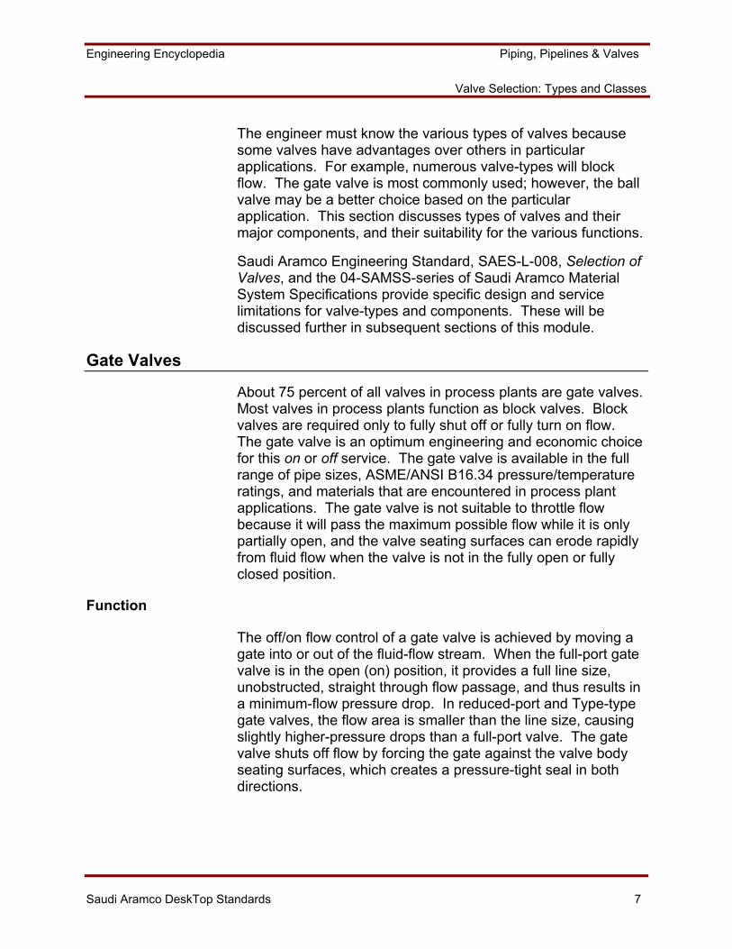
Figure 1. Full-Port Gate Valve
Engineering Encyclopedia Piping, Pipelines & Valves
Valve Selection: Types and Classes
Saudi Aramco DeskTop Standards 9
Major Gate Valve Components
The typical process plant gate valve consists of 20 or more components, as shown in Figure 1. The design of most of these components is standardized, but can vary in detail according to purchaser preference. Seven of these components (the body, gate, bonnet, stem, stem packing system, end connections, and seats) are especially significant and can be obtained in a variety of designs. The selection of a particular component design and/or material depends on both the service conditions and the economics for the application.
Body Pattern
Most standard gate valves are available in either cast or forged steel body construction up to about 100 mm (4 in.) NPS. Body castings are usually supplied for larger gate valves because of the cost and difficulty associated with forging the relatively complex shapes of gate valves in the larger sizes. There are three types of body patterns: full-port, venturi-port, reduced-port.
Full Port –The line size flow area and resulting minimum pressure drop of the full-port valve, shown in Figure 1, make it suitable for all process plant applications where a gate valve is required. Its use is mandatory for systems where pipe scrapers must be employed. However, a full-port valve is usually not the most economical selection, since reduced-port- and venturi-type valves are less expensive. Per API 600, Steel Gate Valves - Flanged and Butt-Welding Ends, full-port is specified for all flanged valves.
Venturi- or Reduced-Port – In the venturi- or reduced-port valve, the seat opening is one or more pipe sizes less than the valve size. This reduces the valve cost due to the overall smaller valve casting size. However, the reduced seat size increases valve pressure drop, reduces its strength to absorb loads from the piping system, and does not permit use of pipe scrapers. Reduced-port valves are available only up to 100 mm (4 in.) in size and are the normal choice in small diameters. A reduced-port is specified for valves that are specified to meet API 602, Compact Steel Gate Valves.
Engineering Encyclopedia Piping, Pipelines & Valves
Valve Selection: Types and Classes
Saudi Aramco DeskTop Standards 10
Gates
There are several different gate designs. The solid- and flexible-wedge gate are the most common. 04-SAMSS-001 defines gate-type requirements for different valve sizes and ratings. For example, a flexible wedge is required for valves 100 mm (4 in.) NPS and larger in ASME/ANSI classes 150 through 600.
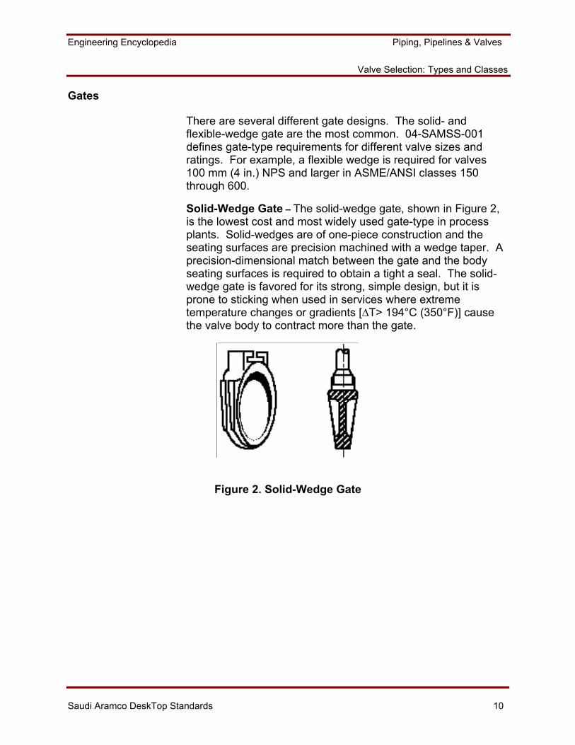
Solid-Wedge Gate – The solid-wedge gate, shown in Figure 2, is the lowest cost and most widely used gate-type in process plants. Solid-wedges are of one-piece construction and the seating surfaces are precision machined with a wedge taper. A precision-dimensional match between the gate and the body seating surfaces is required to obtain a tight a seal. The solid-wedge gate is favored for its strong, simple design, but it is prone to sticking when used in services where extreme temperature changes or gradients [∆T> 194°C (350°F)] cause the valve body to contract more than the gate.
Figure 2. Solid-Wedge Gate
Engineering Encyclopedia Piping, Pipelines & Valves
Valve Selection: Types and Classes
Saudi Aramco DeskTop Standards 11
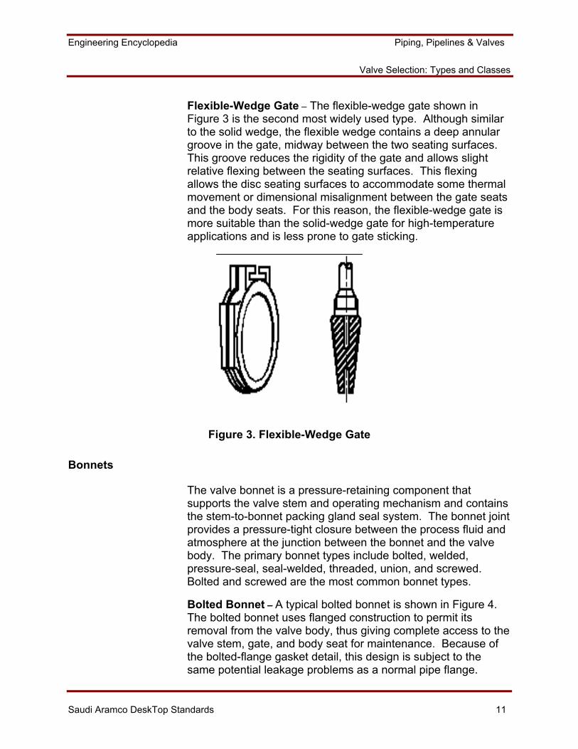
Flexible-Wedge Gate – The flexible-wedge gate shown in Figure 3 is the second most widely used type. Although similar to the solid wedge, the flexible wedge contains a deep annular groove in the gate, midway between the two seating surfaces. This groove reduces the rigidity of the gate and allows slight relative flexing between the seating surfaces. This flexing allows the disc seating surfaces to accommodate some thermal movement or dimensional misalignment between the gate seats and the body seats. For this reason, the flexible-wedge gate is more suitable than the solid-wedge gate for high-temperature applications and is less prone to gate sticking.
Figure 3. Flexible-Wedge Gate
Bonnets
The valve bonnet is a pressure-retaining component that supports the valve stem and operating mechanism and contains the stem-to-bonnet packing gland seal system. The bonnet joint provides a pressure-tight closure between the process fluid and atmosphere at the junction between the bonnet and the valve body. The primary bonnet types include bolted, welded, pressure-seal, seal-welded, threaded, union, and screwed. Bolted and screwed are the most common bonnet types.
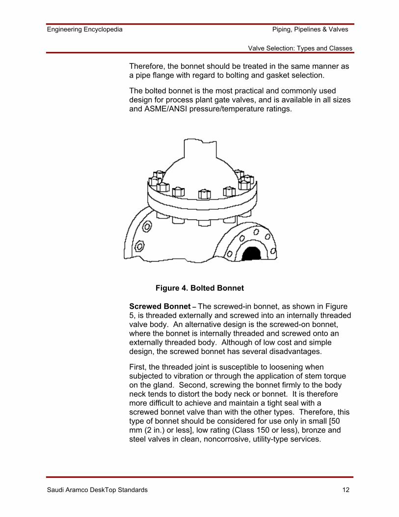
Bolted Bonnet – A typical bolted bonnet is shown in Figure 4. The bolted bonnet uses flanged construction to permit its removal from the valve body, thus giving complete access to the valve stem, gate, and body seat for maintenance. Because of the bolted-flange gasket detail, this design is subject to the same potential leakage problems as a normal pipe flange.
Engineering Encyclopedia Piping, Pipelines & Valves
Valve Selection: Types and Classes
Saudi Aramco DeskTop Standards 12
Therefore, the bonnet should be treated in the same manner as a pipe flange with regard to bolting and gasket selection.
The bolted bonnet is the most practical and commonly used design for process plant gate valves, and is available in all sizes and ASME/ANSI pressure/temperature ratings.
Figure 4. Bolted Bonnet
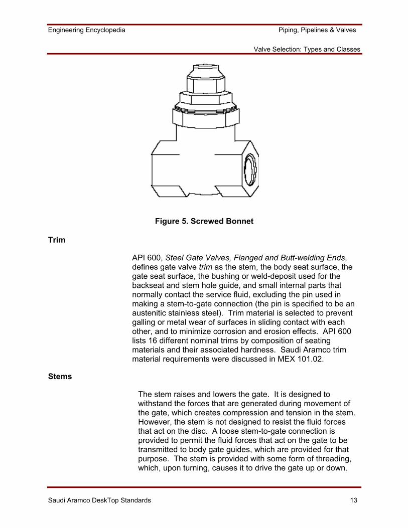
Screwed Bonnet – The screwed-in bonnet, as shown in Figure 5, is threaded externally and screwed into an internally threaded valve body. An alternative design is the screwed-on bonnet, where the bonnet is internally threaded and screwed onto an externally threaded body. Although of low cost and simple design, the screwed bonnet has several disadvantages.
First, the threaded joint is susceptible to loosening when subjected to vibration or through the application of stem torque on the gland. Second, screwing the bonnet firmly to the body neck tends to distort the body neck or bonnet. It is therefore more difficult to achieve and maintain a tight seal with a screwed bonnet valve than with the other types. Therefore, this type of bonnet should be considered for use only in small [50 mm (2 in.) or less], low rating (Class 150 or less), bronze and steel valves in clean, noncorrosive, utility-type services.
Engineering Encyclopedia Piping, Pipelines & Valves
Valve Selection: Types and Classes
Saudi Aramco DeskTop Standards 13
Figure 5. Screwed Bonnet
Trim
API 600, Steel Gate Valves, Flanged and Butt-welding Ends, defines gate valve trim as the stem, the body seat surface, the gate seat surface, the bushing or weld-deposit used for the backseat and stem hole guide, and small internal parts that normally contact the service fluid, excluding the pin used in making a stem-to-gate connection (the pin is specified to be an austenitic stainless steel). Trim material is selected to prevent galling or metal wear of surfaces in sliding contact with each other, and to minimize corrosion and erosion effects. API 600 lists 16 different nominal trims by composition of seating materials and their associated hardness. Saudi Aramco trim material requirements were discussed in MEX 101.02.
Stems
The stem raises and lowers the gate. It is designed to withstand the forces that are generated during movement of the gate, which creates compression and tension in the stem. However, the stem is not designed to resist the fluid forces that act on the disc. A loose stem-to-gate connection is provided to permit the fluid forces that act on the gate to be transmitted to body gate guides, which are provided for that purpose. The stem is provided with some form of threading, which, upon turning, causes it to drive the gate up or down.
Engineering Encyclopedia Piping, Pipelines & Valves
Valve Selection: Types and Classes
Saudi Aramco DeskTop Standards 14
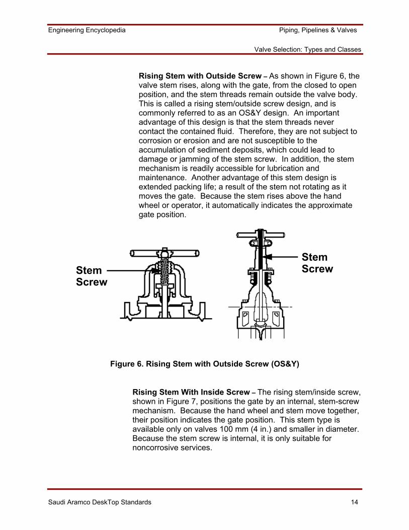
Rising Stem with Outside Screw – As shown in Figure 6, the valve stem rises, along with the gate, from the closed to open position, and the stem threads remain outside the valve body. This is called a rising stem/outside screw design, and is commonly referred to as an OS&Y design. An important advantage of this design is that the stem threads never contact the contained fluid. Therefore, they are not subject to corrosion or erosion and are not susceptible to the accumulation of sediment deposits, which could lead to damage or jamming of the stem screw. In addition, the stem mechanism is readily accessible for lubrication and maintenance. Another advantage of this stem design is extended packing life; a result of the stem not rotating as it moves the gate. Because the stem rises above the hand wheel or operator, it automatically indicates the approximate gate position.
StemScrew
StemScrew
Figure 6. Rising Stem with Outside Screw (OS&Y)
Rising Stem With Inside Screw – The rising stem/inside screw, shown in Figure 7, positions the gate by an internal, stem-screw mechanism. Because the hand wheel and stem move together, their position indicates the gate position. This stem type is available only on valves 100 mm (4 in.) and smaller in diameter. Because the stem screw is internal, it is only suitable for noncorrosive services.
Engineering Encyclopedia Piping, Pipelines & Valves
Valve Selection: Types and Classes
Saudi Aramco DeskTop Standards 15
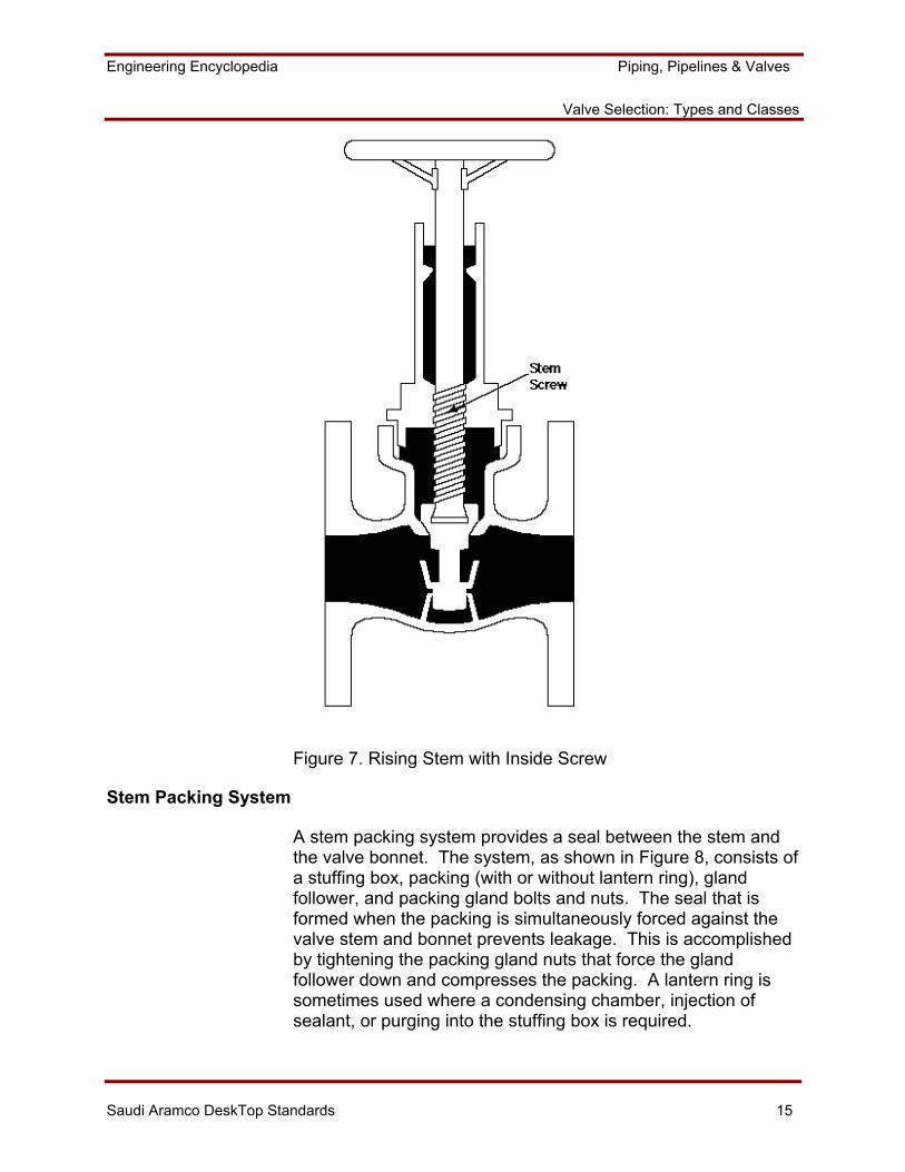
Figure 7. Rising Stem with Inside Screw
Stem Packing System
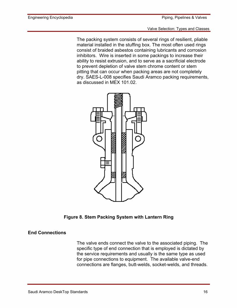
A stem packing system provides a seal between the stem and the valve bonnet. The system, as shown in Figure 8, consists of a stuffing box, packing (with or without lantern ring), gland follower, and packing gland bolts and nuts. The seal that is formed when the packing is simultaneously forced against the valve stem and bonnet prevents leakage. This is accomplished by tightening the packing gland nuts that force the gland follower down and compresses the packing. A lantern ring is sometimes used where a condensing chamber, injection of sealant, or purging into the stuffing box is required.
Engineering Encyclopedia Piping, Pipelines & Valves
Valve Selection: Types and Classes
Saudi Aramco DeskTop Standards 16
The packing system consists of several rings of resilient, pliable material installed in the stuffing box. The most often used rings consist of braided asbestos containing lubricants and corrosion inhibitors. Wire is inserted in some packings to increase their ability to resist extrusion, and to serve as a sacrificial electrode to prevent depletion of valve stem chrome content or stem pitting that can occur when packing areas are not completely dry. SAES-L-008 specifies Saudi Aramco packing requirements, as discussed in MEX 101.02.
Figure 8. Stem Packing System with Lantern Ring
End Connections
The valve ends connect the valve to the associated piping. The specific type of end connection that is employed is dictated by the service requirements and usually is the same type as used for pipe connections to equipment. The available valve-end connections are flanges, butt-welds, socket-welds, and threads.
Engineering Encyclopedia Piping, Pipelines & Valves
Valve Selection: Types and Classes
Saudi Aramco DeskTop Standards 17
Seats
The extent to which tight shutoff is accomplished depends directly on the sealing ability of the seating surfaces, consisting of body seats and gate seats. The ability of two contacting surfaces to form a seal is a function of the degree of surface conformability between them. Perfect contact, (i.e., no voids), gives zero leakage, but this cannot be achieved in practice since an absolutely smooth surface with 100% conformability cannot be attained. The problem therefore is to achieve sufficient conformability to keep the leakage rate within acceptable limits.
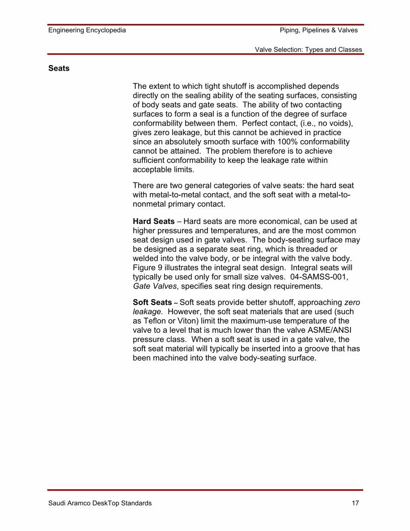
There are two general categories of valve seats: the hard seat with metal-to-metal contact, and the soft seat with a metal-to-nonmetal primary contact. Hard Seats – Hard seats are more economical, can be used at higher pressures and temperatures, and are the most common seat design used in gate valves. The body-seating surface may be designed as a separate seat ring, which is threaded or welded into the valve body, or be integral with the valve body. Figure 9 illustrates the integral seat design. Integral seats will typically be used only for small size valves. 04-SAMSS-001, Gate Valves, specifies seat ring design requirements.
Soft Seats – Soft seats provide better shutoff, approaching zero leakage. However, the soft seat materials that are used (such as Teflon or Viton) limit the maximum-use temperature of the valve to a level that is much lower than the valve ASME/ANSI pressure class. When a soft seat is used in a gate valve, the soft seat material will typically be inserted into a groove that has been machined into the valve body-seating surface.
Engineering Encyclopedia Piping, Pipelines & Valves
Valve Selection: Types and Classes
Saudi Aramco DeskTop Standards 18
Body-to-GateSeat Interface
IntegralSeat
Figure 9. Integral Seat
Ball Valve
Ball valves usually function as block valves to fully shut off or fully open flow. Ball valves are well suited for conditions where quick on/off and/or bubble-tight service are required. The ball valve is available in the full range of pipe sizes and materials that are needed in process plant applications, and most soft-sealed models are suitable for double-block and bleed applications. However, it is important to note that pressure/temperature ratings for ball valve soft seats, above ambient temperatures, are usually lower than the ASME/ANSI ratings for steel valves. This is because of the lower physical properties of the soft-seat materials. Soft-sealed ball valves are not normally used for throttling service because the valve soft-seats are subject to erosion or distortion/displacement caused by fluid flow when the valve is not in the fully open or fully closed position.
Engineering Encyclopedia Piping, Pipelines & Valves
Valve Selection: Types and Classes
Saudi Aramco DeskTop Standards 19
The soft-sealed ball valve is a good choice as a block valve when used within the limitations previously mentioned and when bubble-tight shutoff, double-block and bleed capability, or the quick on/off feature is required. Where such capabilities are not required, the ball valve is usually not the best choice in most sizes, because of its higher cost relative to gate valves.
Figure 10. Full-Bore Ball Valve
Engineering Encyclopedia Piping, Pipelines & Valves
Valve Selection: Types and Classes
Saudi Aramco DeskTop Standards 20
Function
The ball valve is quick-opening and requires only a quarter-turn from full open to full closed. A ball is used to permit or block flow. A hole, provided through one axis of the ball, connects with the inlet and outlet ports of the valve body. With the ball in the open position, straight-through flow is accomplished. When the ball is turned 90°, flow is blocked. In the closed position, tight shutoff is obtained by resilient, seat-to-metal ball-sealing contact, and to a lesser degree, by metal-to-metal contact in metal-seated models.
Major Ball Valve Types and Components
The following describes some major ball valve types and components that directly influence function or differentiate ball valves from other valves. Refer to Figure 10.
Types
Most ball valve models have soft-sealed body seat designs, but are frequently of a non-fire safe-type that is generally unsuitable for process service. There are two basic seating types for process service applications: the nonresilient, seated- (metal, carbon-graphite, etc.) and the soft-sealed, fire safe-type. Only the soft-sealed, fire safe design will be discussed, since that is the type that is required most often.
Fire safe ball valves utilize a narrow-band primary-seal ring of a soft, resilient material (such as Teflon) in the body seats to prevent leakage through the annulus between the ball and body cavity. Fire safe ball valves also include a secondary, metal-to-metal seal (see Figure 11) to assure a positive shutoff capability in the event of fire or other damage to the soft seals. They also require high-temperature stem packings, cover gaskets, and external bolting materials to minimize external leakage in a fire situation.
Engineering Encyclopedia Piping, Pipelines & Valves
Valve Selection: Types and Classes
Saudi Aramco DeskTop Standards 21
Body
The body of a ball valve contains and supports the ball, stem, and operating mechanism. There are several body designs available, but all fall into the two basic categories of one-piece or multi-piece designs.
Multi-piece Body – In the multi-piece body design, the valve body is circumferentially divided into pieces, thereby permitting the ball and seats to be installed or removed by disassembling the body. This is illustrated in Figure 10. The body segments are fastened together by flanging, screwing, or with long through-bolts. However, the exposed through-bolt arrangement is not recommended for fire safe valve applications, as direct-flame impingement can cause bolt relaxation and substantial external joint leakage.
The multi-piece body is acceptable for use in all utility services, but must be certified fire safe for use in hydrocarbon services. The vendor should certify that the body joint(s) are capable of withstanding full-pipe stresses with no resultant joint leakage.
One-piece Body – There are three basic one-piece body designs: the end-entry, top-entry and sealed (welded) designs.
In the end-entry-type, the ball and seats are installed axially and retained by an axial retaining ring. One desirable feature of this design is the ability to eliminate one external leakage path by eliminating one body joint, usually required on other types for ball and seat installation. However, this configuration has a safety hazard in that faulty retention of the ball could result in blowout when the downstream flange of the valve is disconnected under pressure, unless the retaining ring design can be locked in.
In the top-entry body-type, the ball and seats are fit into the top of the valve and retained by a cover or bonnet. This body construction permits inline maintenance of the valve to the extent of replacing the ball or seats. This is a particular advantage for valves that are butt-welded, seal-welded, or socket-welded into the line.
Engineering Encyclopedia Piping, Pipelines & Valves
Valve Selection: Types and Classes
Saudi Aramco DeskTop Standards 22
The sealed-body design uses welded construction. The ball and seats are positioned in the body before welding the body seams. While sealing a valve by welding eliminates external leakage, it restricts inspection and maintenance of the valve internals, in that cutting and re-welding of the valve body would be required to provide internal access.
Ball
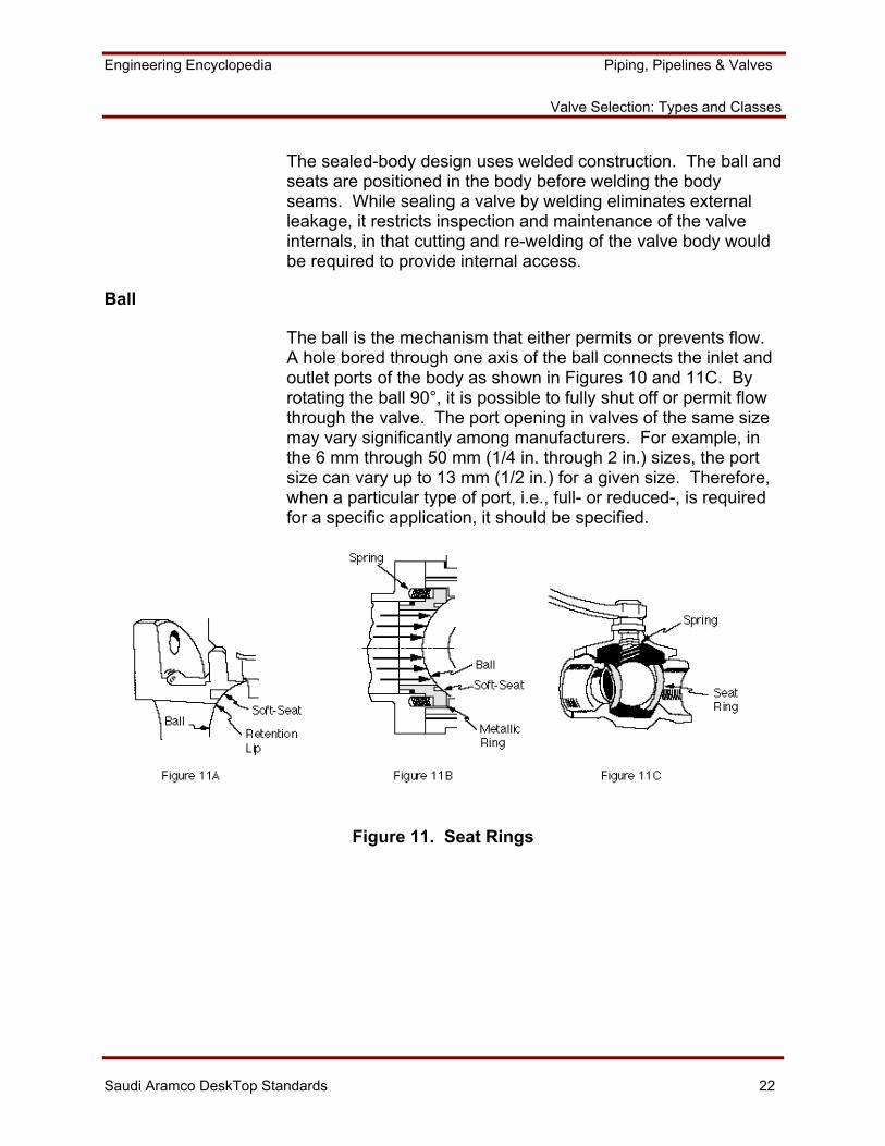
The ball is the mechanism that either permits or prevents flow. A hole bored through one axis of the ball connects the inlet and outlet ports of the body as shown in Figures 10 and 11C. By rotating the ball 90°, it is possible to fully shut off or permit flow through the valve. The port opening in valves of the same size may vary significantly among manufacturers. For example, in the 6 mm through 50 mm (1/4 in. through 2 in.) sizes, the port size can vary up to 13 mm (1/2 in.) for a given size. Therefore, when a particular type of port, i.e., full- or reduced-, is required for a specific application, it should be specified.
Figure 11. Seat Rings
Engineering Encyclopedia Piping, Pipelines & Valves
Valve Selection: Types and Classes
Saudi Aramco DeskTop Standards 23
Seats
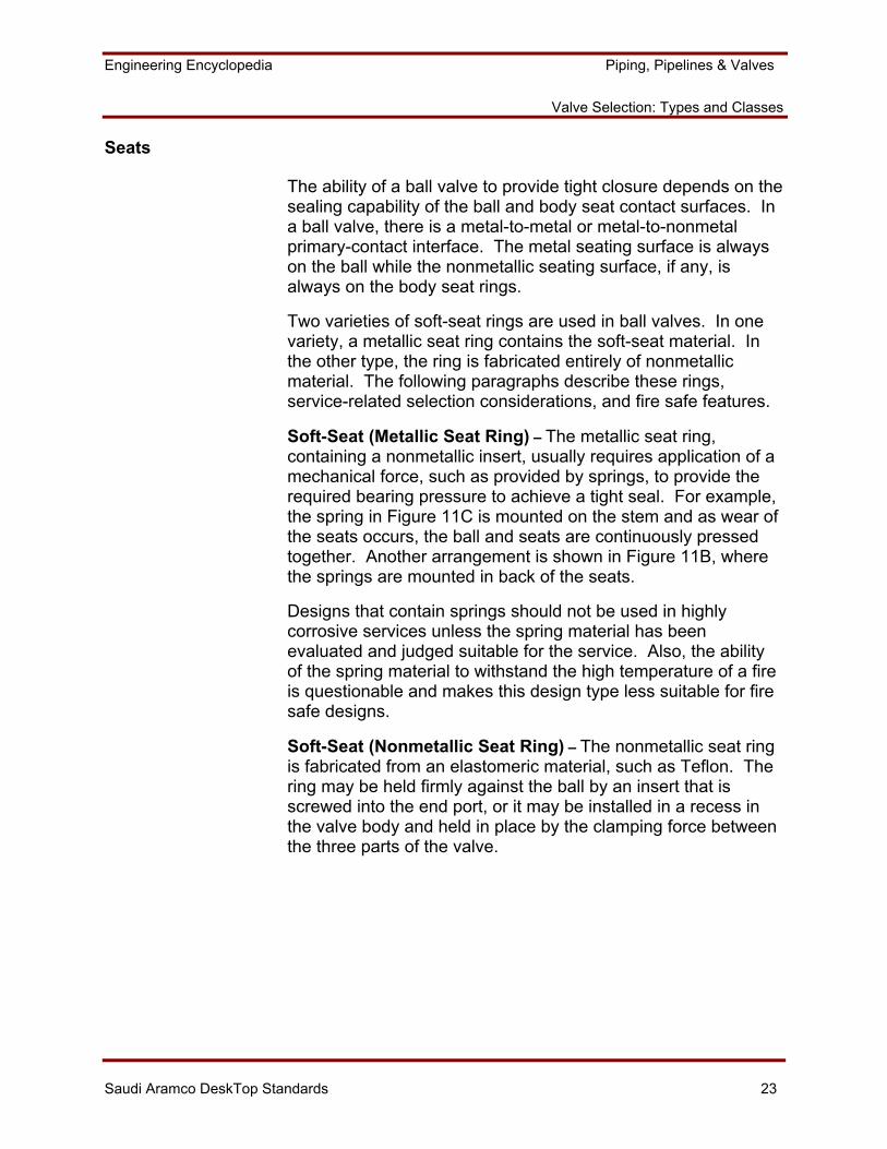
The ability of a ball valve to provide tight closure depends on the sealing capability of the ball and body seat contact surfaces. In a ball valve, there is a metal-to-metal or metal-to-nonmetal primary-contact interface. The metal seating surface is always on the ball while the nonmetallic seating surface, if any, is always on the body seat rings.
Two varieties of soft-seat rings are used in ball valves. In one variety, a metallic seat ring contains the soft-seat material. In the other type, the ring is fabricated entirely of nonmetallic material. The following paragraphs describe these rings, service-related selection considerations, and fire safe features.
Soft-Seat (Metallic Seat Ring) – The metallic seat ring, containing a nonmetallic insert, usually requires application of a mechanical force, such as provided by springs, to provide the required bearing pressure to achieve a tight seal. For example, the spring in Figure 11C is mounted on the stem and as wear of the seats occurs, the ball and seats are continuously pressed together. Another arrangement is shown in Figure 11B, where the springs are mounted in back of the seats.
Designs that contain springs should not be used in highly corrosive services unless the spring material has been evaluated and judged suitable for the service. Also, the ability of the spring material to withstand the high temperature of a fire is questionable and makes this design type less suitable for fire safe designs.
Soft-Seat (Nonmetallic Seat Ring) – The nonmetallic seat ring is fabricated from an elastomeric material, such as Teflon. The ring may be held firmly against the ball by an insert that is screwed into the end port, or it may be installed in a recess in the valve body and held in place by the clamping force between the three parts of the valve.
Engineering Encyclopedia Piping, Pipelines & Valves
Valve Selection: Types and Classes
Saudi Aramco DeskTop Standards 24
Any of these designs are acceptable for use in utility services. However, for a fire safe design, a secondary metal-to-metal seating arrangement is required to limit leakage in the event that the soft-seat material is lost during a fire. This is accomplished by including a metal retention lip on the valve body or insert as shown in Figures 11A. Upon loss of the soft seat, the line pressure forces the ball against this metal retention lip (secondary seat) to effect a tight closure.
Ball Supports
There are two basic designs for supporting the ball within the valve body: the seat-supported, and the trunnion-supported designs.
In the seat-supported design, the ball is supported by the seat rings. In the trunnion design, the ball is supported by a trunnion that is attached to the bottom of the ball. The trunnion fits into a recess in the bottom of the valve body where it is supported and guided when the ball is rotated.
Plug Valve
Plug valves usually function as block valves to fully shut off or fully open flow. They are well suited for conditions where quick on/off and/or bubble-tight shutoff are required. Most plug valve styles are available in the full range of pipe sizes and materials that are needed in process plant applications. Soft-sealed styles with full cylindrical plugs are suitable for double-block and bleed applications. The soft-seal-types, however, may have lower temperature/pressure ratings than those given in ASME/ANSI B16.34 for steel valves, because of the lesser physical properties of the soft-seat materials. Soft-seal plug valves are not normally used for throttling service, since the soft seals are subject to erosion or distortion/displacement caused by fluid flow when the valve is not in the fully open or closed position.
A plug valve is a good choice as a block valve when used within the limitations noted above, and when bubble-tight shutoff or quick on/off operation is required.
Engineering Encyclopedia Piping, Pipelines & Valves
Valve Selection: Types and Classes
Saudi Aramco DeskTop Standards 25
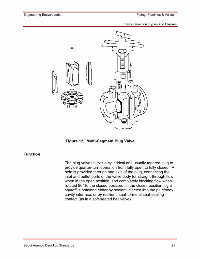
Figure 12. Multi-Segment Plug Valve
Function
The plug valve utilizes a cylindrical and usually tapered plug to provide quarter-turn operation from fully open to fully closed. A hole is provided through one axis of the plug, connecting the inlet and outlet ports of the valve body for straight-through flow when in the open position, and completely blocking flow when rotated 90° to the closed position. In the closed position, tight shutoff is obtained either by sealant injected into the plug/body cavity interface, or by resilient, seat-to-metal seat-sealing contact (as in a soft-seated ball valve).
Engineering Encyclopedia Piping, Pipelines & Valves
Valve Selection: Types and Classes
Saudi Aramco DeskTop Standards 26
Major Plug Valve Types and Components
The following describes some major plug valve components and types that directly influence function or differentiate plug valves from other valves. Refer to Figure 12.
Types
There are three basic plug valve-types: the lubricated, nonlubricated, and soft-sealed fire safe. Nonlubricated, nonfire safe plug valves have few applications in process plants and will not be discussed.
Lubricated Plug Valve – A lubricated plug valve depends on injection of a sealant to prevent leakage around the plug through the interface between the plug and the body cavity. The sealant is injected through a pressure fitting into the body cavity and distributed across all seating surfaces via grooves in the plug. The sealant material must be compatible with the process fluid, resist breakdown at maximum design temperature, and retain its fluidity and lubricating properties at minimum design temperature.
Lubricated plug valves can provide good long-term performance if adequate maintenance attention can be ensured. With its substantial secondary metal-to-metal seating and capacity for restoring tight shutoff by sealant injection, this valve-type is inherently fire safe with respect to through-leakage. However, appropriate high-temperature stem packings, gaskets, and supplementary seals must be provided to ensure fire safe integrity against external leakage.
Soft-Sealed, Fire safe Plug Valve – Fire safe plug valves use a narrow-band primary-seal ring of a soft, resilient material (such as Teflon) in the annulus between the plug and body cavity to prevent leakage. A fire safe soft-sealed plug valve also has a secondary metal-to-metal backup seal. This assures positive shutoff capability if the soft seal is damaged by fire. The maximum temperature limit of the valve is limited by the soft-seal material.
Engineering Encyclopedia Piping, Pipelines & Valves
Valve Selection: Types and Classes
Saudi Aramco DeskTop Standards 27
Body
Plug valves are typically of the one-piece body design, with top or bottom entry. Body styles include the short pattern, regular (reduced-port) pattern, venturi pattern, and the round-port full-bore pattern.
The short pattern design has the same face-to-face dimensions as Classes 150 and 300 flanged steel gate valves. This pattern is advantageous when replacing existing gate valves or when there are space restrictions.
Regular pattern (reduced-port) designs have a smaller plug-port area than do full-bore valves, are less expensive, and represent the most commonly available style. They may be used in cases where pressure drop is not critical and the service application does not require scraping or rodding.
Venturi-pattern designs provide maximum weight and cost savings, because they have the smallest port area for a given nominal valve size. Their use restrictions are the same as for regular pattern valves.
The round-port full-bore pattern is the most expensive for a given nominal size, but is required where pressure drop is critical or where scraping or rodding will be required.
Plug Styles and Seating Mechanisms
The plug opens or closes the flow path through the valve. A full- or reduced-bore hole through one axis of the plug permits straight-through flow when aligned with the longitudinal valve axis and flow is blocked when the plug is rotated 90° to the closed position. Common plug configurations are the full cylindrical (usually tapered), and eccentric-cylindrical segment styles.
The most common style is the full-cylindrical tapered plug, with sealant grooves for the lubricated-type valve or resilient-seat inserts for the soft-seal-type valve. This configuration is best suited to the constant wedge- seating mechanism used with lubricated plugs and to the lift-off, turn and reseat design used for some nonlubricated types.
Engineering Encyclopedia Piping, Pipelines & Valves
Valve Selection: Types and Classes
Saudi Aramco DeskTop Standards 28
In the lift-off turn and reseat plug design, as the hand wheel is rotated from the fully open or fully closed position, the stem guide arrangement causes the plug to rise slightly out of the body seat taper, rotate 90°, then reseat with a final downward thrust. This feature minimizes operating torque and seat wear, since there is no contact with the body seats during plug rotation, and the plug/body seating surfaces are shielded from the process fluid for both the open and closed positions.
Another plug style is the eccentric-mounted cylindrical segment. The metal plug is equipped with resilient-seat inserts or a full resilient facing for bubble-tight shutoff, or is all metal faced for high-temperature applications where tight shutoff is not required. The eccentric mounting of the plug causes a radial thrust into the seats when the plug is rotated to the closed position. This affords tight shutoff by seat compression but avoids the frictional seat wear that accompanies plug rotation when plugs and body seats are mounted concentrically. This plug style may not be used in double block and bleed applications, since there is only a single (downstream) sealing face.
Plug Support
There are two basic methods of plug support: floating (or seat) support, and trunnion support. These are analogous to the support designs that are used in ball valves.
Seats
The degree of closure afforded by a plug valve depends on the sealing capability of the plug and body seats. Where tight closure is required, lubricated or soft-seal fire safe plug valves may be used within the temperature limits of the lubricant or soft-seal material.
For lubricated plug valves, the sealant provides the seal. The second style uses metal seats with resilient inserts, required for fire safe applications.
Sealant Seating (Lubricated Plugs) – For lubricated plug valves, the sealant is the sealing mechanism as well as the lubricant for the metal-to-metal seating interfaces. Bubble-tight shutoff can be obtained when sealant is initially injected. However, sealant pressure will dissipate with time via slow
Engineering Encyclopedia Piping, Pipelines & Valves
Valve Selection: Types and Classes
Saudi Aramco DeskTop Standards 29
leakage through the seating interface and periodic sealant injection is required to maintain tight shutoff, particularly at higher temperatures. The sealant must be chemically compatible with the process fluid and have appropriate viscosity for the intended operating temperature.
Combined Soft-Seal and Metal-to-Metal Seating, Fire safe Design – The usual configuration for this seal-type is the inclusion of a resilient material, such as Teflon or Viton, in a retaining groove that is machined in the valve plug. The soft-seal material must be chemically compatible with the process fluid and adequate for the maximum design temperature. Teflon is inert to most process fluids and has a maximum temperature limit of 232°C (450°F). Viton is more resilient than Teflon, but is less resistant to some process fluids and has a 204°C (400°F) temperature limit. Other resilient seals are available, but their temperature limits are generally lower. This seal-type is suitable for fire safe service applications, due to its back-up metal-to-metal seating in the case of fire damage to the soft seals. However, a fire safe design must also incorporate appropriate stem seals, cover gaskets, and cover bolting materials to minimize external leakage, as well.
Engineering Encyclopedia Piping, Pipelines & Valves
Valve Selection: Types and Classes
Saudi Aramco DeskTop Standards 30
SELECTING THE TYPE AND SIZE OF A VALVE THAT IS SUITABLE FOR PROCESS APPLICATIONS
Selecting the appropriate valve depends on the fluid in a piping system, the system's design conditions, the service application, the functions and types of valves (as discussed earlier in this module), and the applicable SAES and SAMSS requirements. Other considerations for selecting valves are discussed in further detail in this section.
SAES-L-008 and the 04-SAMSS-series provide requirements and limitations for valve selection. The valve selection procedure, as described below and summarized in Work Aid 1, is a guide for selecting the appropriate valve for the three primary functions discussed earlier. However, it is important to understand that selecting valves may simply be a matter of duplicating valves from a system that has provided good performance. Similarly, good experience with a particular valve model in one service often justifies using the same model elsewhere in an essentially identical service.
Engineering Encyclopedia Piping, Pipelines & Valves
Valve Selection: Types and Classes
Saudi Aramco DeskTop Standards 31
Step 1: List the Data Required
Basic piping system design and valve application data are required before a valve can be selected.
Data Required Where to Find Data
1. Fluid service. (Such as steam, crude oil)
Design Specifications.
Refer to service categories summarized in SAES-L-008.
2. Valve function. (Block, throttling) By knowledge of function desired.
3. Design temperature and pressure. Design Specifications.
4. Material and corrosion allowance. Design Specifications, SAES-L-008.
5. Application. (Such as isolation, product segregation)
By knowledge of function desired.
6. Special features desired. (Such as quick on/off, bubble-tight shutoff).
Design Specifications; process engineer, operating experience.
7. Size. Design Specifications.
Review of the data that is collected will begin to narrow the choices of potentially suitable valves. For example, if a block valve is needed, all the check valve-types are immediately eliminated from consideration.
Valve Sizing
In most cases, valve size is identical to pipe size. In some cases, a valve must be larger than the pipe in order to pass the required flow-rate due to pressure drop across the particular valve-type being used. In other cases, it might be advantageous for a valve to be smaller for economic reasons.
When fluid is flowing steadily in a long, straight pipe of uniform diameter, the flow pattern assumes a certain characteristic form. Any disruption, such as due to friction, will cause a drop in pressure. Valves also disrupt the flow pattern and, therefore,
Engineering Encyclopedia Piping, Pipelines & Valves
Valve Selection: Types and Classes
Saudi Aramco DeskTop Standards 32
cause a pressure drop in the piping system. The loss of pressure produced by a valve consists of:
• The pressure drop within the valve itself.
• The pressure drop in the upstream and downstream piping that exceeds what would normally occur if there was no valve in the line.
Equations are used to calculate the pressure drop across a valve, based on the flow characteristics of the particular valve-type. It must be determined whether the pressure drop is acceptable for the process design requirements. Since the pressure drop caused by valves can affect the size of the valve, it can also influence the selection of one valve-type over another, since different valve-types have different pressure-drop characteristics. It is also normally the process design engineer who determines whether the system pressure drop is acceptable. Further discussion of pressure drop across valves is beyond the scope of this course.
Step 2: Identify Suitable Valve-Types and Components
Based on the required valve function and other applicable data, numerous valve-types may be suitable for a particular service. The previous section on valve-types discussed the suitability of valve-types for particular functions. A chart included in Work Aid 1 matches valve functions with suitable types. This information is then combined to develop a list of the valve types suitable for the application. At this point in the process, there may still be multiple candidates, in which case the following should be considered:
• A gate valve will be used for most block valve applications.
• A globe valve will be used for most throttling applications.
• A swing check valve will be used for most flow-reversal prevention applications.
Engineering Encyclopedia Piping, Pipelines & Valves
Valve Selection: Types and Classes
Saudi Aramco DeskTop Standards 33
Step 3: Determine Valve-Type Limitations for Suitable Valves through Saudi Aramco Engineering Standard SAES-L-008, Selection of Valves
Saudi Aramco Engineering Standard SAES-L-008, Selection of Valves, provides limitations on the use of specific valve-types for particular applications. It also contains materials requirements for the valve body, trim and packing.
SAES-L-008 discusses:
• The limitations on the selection of all valves normally classified under the 04-SAMSS-series. Where applicable, this standard supplements the requirements of the ASME/ANSI B31 Codes for pressure piping.
• General design limitations for major valve components. These include:
Bonnets
− Pressure-seal bonnets shall only be used in steam or other clean, noncorrosive services. A pressure-seal bonnet valve relies on a metal-to-metal seal to prevent external leakage at the bonnet. Corrosive- or high-fouling-type services could affect the long-term reliability of this metal-to-metal seal.
− Welded bonnet valves are limited to a 50 mm (2 in.) maximum size. They are generally also not permitted in wet, sour service except where severe vibration is expected. A welded bonnet valve does not permit easy internal access. Therefore, their use is limited to low-cost valves (i.e., small size) where they will be discarded rather than maintained. They are generally not used in wet, sour service since a higher degree of maintenance could be expected.
− Screwed bonnet or body valves must have a locking pin or be tack-welded to the valve body for all hydrocarbon or hazardous services. The concern here is that the threaded joint may become loose and leak during operation.
Engineering Encyclopedia Piping, Pipelines & Valves
Valve Selection: Types and Classes
Saudi Aramco DeskTop Standards 34
− Union bonnet valves are not permitted in any hydrocarbon or hazardous services. Here again, the concern is that the connection may loosen and leak during operation.
End Connections − Valve end connection requirements and limitations are
generally identical to those of other pipe and fittings, as specified in SAES-L-010.
− If valves have soft seats, and have either threaded ends with seal welds or are socket-welded, the soft seats must be removed before welding or the valves supplied with factory-installed nipples. The concern here is that if field welding is done too close to the valve seats, the welding heat will damage the seats.
Ratings − The ratings for soft-seated valves must be suitable for the
design conditions and consider any limitations of the soft-seat material. The maximum permitted temperature for a soft-seat-type valve is typically in the range 93-232°C (200-450°F), depending on the soft-seat material used.
− In hydrocarbon services, the minimum rating for threaded- and socket-welded-type valves 50 mm (2 in.) NPS and smaller in size must be Class 800 per API 602. This ensures a basic strength in these small valves to withstand mechanical or physical abuse, not just the design pressure/temperature.
Stem Packing − Isolation valves 75 mm (3 in.) NPS and larger in
hydrocarbon services shall not have stem packing or seals that are pure polymer or elastomer, unless the valves are qualified as being firesafe. The concern here is that in the event of a fire in the vicinity, these packing materials would be destroyed and significant leakage from the packing gland would make the fire worse.
Stems − Inside screw/rising stem (ISRS) and nonrising-stem
(NRS) valves 38 mm (1 1/2 in.) NPS and smaller shall not be used in corrosive hydrocarbon services. The
Engineering Encyclopedia Piping, Pipelines & Valves
Valve Selection: Types and Classes
Saudi Aramco DeskTop Standards 35
concern here is that the stem threads could corrode and thus hinder valve movement.
• Specific valve-type limitations. These include:
Ball Valves − Stems must be blowout-proof. This is required to permit
loosening the packing gland and repacking the valve while the system is under pressure.
− Welded-body-type ball valves cannot be used in services where damage to the soft seats during commissioning and/or operation cannot be avoided and must be anticipated. Internal maintenance on this valve-type is difficult, since the valve body must be cut open for access. Therefore, it should not be used where seat damage can be anticipated.
Butterfly Valves − Concentric butterfly valves are permitted only in
nonhydrocarbon, noncritical applications. Such a valve design cannot have firesafe capability, so it could not be used as a block valve for other than these services.
− High-performance butterfly valves in hydrocarbon service are limited to ASME/ANSI Class 300. They must meet API 609, Lug- And Wafer-Type Butterfly Valves, and have an offset-seat construction, be firesafe, generally have a full-lug design, and not have a preferred flow direction. These requirements permit using this potentially lower-cost valve option for the lower ANSI Classes, while ensuring a high-quality valve is obtained (API 609 and firesafe), and that it will seal against flow from either direction.
Check Valves − Dual- and single-plate wafer check valves shall not be
used in pulsating services, such as in reciprocating pump or compressor systems. The concern here is that the pressure pulsations will cause the valve discs to continually open and shut, and lead to eventual fatigue failure of the closure springs or plates.
− Nonslam-type check valves must be installed in the discharge lines of pumps or compressors that are installed in parallel. In such an arrangement, the
Engineering Encyclopedia Piping, Pipelines & Valves
Valve Selection: Types and Classes
Saudi Aramco DeskTop Standards 36
equipment is spared and will be periodically switched in operation. This will lead to a flow-reversal situation which is part of normal operation, rather than being an upset. Thus a nonslam-type check valve (i.e., one without spring-assisted closure) would be less prone to disk failure resulting from repeated operation.
• Specific service limitations. These include:
Low-temperature Service − The requirements of Saudi Aramco Material System
Specification 04-SAMSS-003, Additional Requirements for Low-Temperature Valves, must be met for services between -45 and 0°C (-50 and 32°F). These requirements are meant to prevent brittle fracture of the valve body.
− Valves for services less than -45°C (-50°F) must be austenitic stainless steel and meet 04-SAMSS-003. Again, this is for brittle fracture prevention.
− All valves in services below -100°C (-150°F) must have extended bonnets. An extended bonnet valve is equipped with bonnet/stem extensions, with the packing gland located at the top. This provides an insulating gas column to moderate the temperature in the packing gland region. This avoids excessive packing shrinkage and ice-up around the stem, which can cause external leakage or valve cycling problems, respectively.
Underwater Valves − Isolation valves must be ball-type per 04-SAMSS-051,
Ball Valves, and have a minimum rating of ASME/ANSI Class 300. The quick-shutoff capability of a ball valve is desirable in underwater applications. The Class 300 provides a minimum degree of mechanical strength for use in underwater applications, even if Class 150 would be sufficient based on pressure/temperature considerations alone.
Isolation Services − Only gate, ball, or plug valves may be used as isolation
valves in pressure-relief valve inlet and discharge piping, flare systems, or for emergency isolation. These are critical, plant safety-related applications, and these valve-types are felt to be the most reliable.
Engineering Encyclopedia Piping, Pipelines & Valves
Valve Selection: Types and Classes
Saudi Aramco DeskTop Standards 37
− Gate valves used around pressure-relief valves or in flare systems must be installed with the stem installed either horizontal or sloping down, away from the valve. These valves will normally be full-open when the unit is in operation to permit unimpeded flow through the safety systems. It is essential from a safety standpoint that these lines remain unobstructed. Mounting gate valves as specified ensures that the flow passage will remain open if the stem fails. If gate valves are mounted otherwise, a stem failure could permit the gate to fall shut, thus blocking the safety-relief path. This concern does not exist for either ball or plug valves, since a stem failure would not cause movement of their closure components.
− Soft-seated emergency isolation valves are to be certified firesafe in accordance with specified industry standards. Isolation valves are often needed to segregate sections of a plant during a fire, so they must be able to perform this function even if the soft seat is damaged.
− Emergency shutdown (ESD) valves must be ball valves with a suitable power actuator. These valves must fully close in the shortest possible time, thus leading to the use of ball valves.
− Flangeless valves shall not be used as the first block valve against storage tanks or vessels that contain hazardous materials. A flangeless valve is mounted between two pipe flanges, with gaskets on each side of the valve and long studs that span the flanges and valve. This results in two, gasketed joints being held tight by one set of studs. The concern with such a valve in the stated applications is in a fire situation. Thermal expansion of the long studs due to the heat of a fire could cause the gasketed joints to loosen and significant external leakage to occur. Thus the closed block valve would be ineffective in keeping the large volume of hazardous material from adding to the emergency.
• Materials limitations. These include: − Valves with bodies of cast or ductile iron, or low melting-
point alloys such as brass or bronze, shall not be used in hydrocarbon services. In the event of a fire in the vicinity, valves made of these relatively low-strength materials could easily fail and add more fuel to the fire.
Engineering Encyclopedia Piping, Pipelines & Valves
Valve Selection: Types and Classes
Saudi Aramco DeskTop Standards 38
− Valves with either steel or ductile iron bodies must be used in several specified applications. However ductile iron still cannot be used in hydrocarbon services, as previously stated. The specified applications are:
+ The first valve on all tanks and vessels if valve failure could result in personnel or fire hazard, or a large monetary loss.
+ Isolation valves on main utility lines entering a plant area, where the operating and shut-off valves are cast iron or nonferrous construction.
+ In hazardous areas where it is essential that the valve do not fail in a fire, as in aboveground firewater-system block valves.
The valve applications identified are critical from a safety standpoint. Therefore, these requirements ensure that low-strength body materials are not permitted.
− Minimum valve material requirements are specified based on fluid service. Asbestos gaskets and packing are not to be used whenever there is a technically acceptable nonasbestos product available.
SAES-L-008 also provides tables that provide service and application requirements.
• Table I, Service and Application Requirements, Valve Body and Trim Material, must be referred to for all valve applications. It specifies acceptable valve body and trim materials based on the fluid environment, concentration, and design temperature. The main focus of this table is gate valves, but its requirements are also to be applied to other valve-types as applicable.
• Table II, Alternate Stem and Spring Materials, provides acceptable alternatives for situations in which a different material from the trim specified in Table I is desirable for a valve stem or spring. This might be necessary for fabrication, availability, or cost reasons.
• Table III, Service & Application Requirements, Plastic/Elastomeric Components, must be referred to for soft-seated-type valves. It specifies acceptable materials for nonmetallic valve components based on the fluid environment.
Engineering Encyclopedia Piping, Pipelines & Valves
Valve Selection: Types and Classes
Saudi Aramco DeskTop Standards 39
• Table IV, Metallic Materials Designations, defines the abbreviations that are used in the standard.
• Table V, Packings, must be used to specify packing material based on fluid service and design temperature.
• Table VI, Gaskets, must be used to specify valve-bonnet gaskets. This table is used in conjunction with Tables I, III, and V, and the gasket-type being used for piping.
Step 4: Finalize Valve Selection by Considering Other Factors
When two or more valves are found to be suitable for a specific service, several additional factors must be evaluated before making the final selection.
Standardization
There may be strong preferences for certain valve types for particular applications or at certain sites. This information can be found in the piping specifications, material inventory, maintenance department office, or purchasing department notes.
Inventory
Certain valves may be available, avoiding the need for new purchases.
Experience
Good or bad experience with certain valve-types in similar situations may influence the final selection. Data may be available from operations or maintenance departments.
Engineering Encyclopedia Piping, Pipelines & Valves
Valve Selection: Types and Classes
Saudi Aramco DeskTop Standards 40
Cost
Sometimes two valves can be suitable, but one may be less expensive. Data should be obtained from a cost estimating manual, vendors, or the purchasing department.
Delivery Time
Valves of large size, alloy, or high-pressure class may have a delivery time of six months to two years. This should be checked if there is a possibility of hampering project completion.
Materials
Substitution of a different but acceptable material may permit cost or delivery time credits. SAES-L-008 and the 04-SAMSS-series provide material requirements.
Dimensions
Replacement valves should have the same face-to-face dimensions as the original valves.
After evaluating all the criteria, it may be found that none of the valve types being considered is ideal. At this point, consideration must be given to using less stringent criteria. For example, can a higher cost be justified to gain greater service reliability?
Step 5: Provide a Full Description
A full description of a valve-type requires the engineer to specify additional information, as summarized in Work Aid 1. The 04-SAMSS-series provides additional design requirements for specific valve-types. These include:
• References to appropriate industry standards and other Saudi Aramco requirements.
• Modifications to industry standards to make a valve suitable for Saudi Aramco applications.
• Specific design, materials, testing, inspection, marking, and shipping requirements that are appropriate for Saudi Aramco applications. These typically go beyond what is already
Engineering Encyclopedia Piping, Pipelines & Valves
Valve Selection: Types and Classes
Saudi Aramco DeskTop Standards 41
specified in an industry standard, make selections where options are available, or provide coverage where none is available and Saudi Aramco does not wish to accept the valve manufacturer's standard design.
The following summarizes the SAMSS's that relate to valves:
• 04-SAMSS-001 - Gate Valves.
• 04-SAMSS-002 - Globe Valves.
• 04-SAMSS-003 - Additional Requirements for Low-Temperature Valves.
• 04-SAMSS-005 - Check Valves, Swing-Type.
• 04-SAMSS-035 - General Requirements for Valves.
• 04-SAMSS-041 - Expanding Plug Valve.
• 04-SAMSS-042 - 4-Way Diverter Valve.
• 04-SAMSS-048 - Valve Inspection and Testing Requirements.
• 04-SAMSS-049 - Inspection and Testing Requirements for API 6A 10,000 psi Valves.
• 04-SAMSS-050 - Gate Valves, Through-Conduit-Type, API 6D.
• 04-SAMSS-051 - Ball Valves, API 6D.
• 04-SAMSS-052 - Ball Valves, API 6A.
Note that several of the valve-types that are included in the listed SAMSS's were not discussed. These are beyond the scope of this course. It should also be noted that 04-SAMSS-003 applies to all valves with a minimum design temperature between 0°C and -46°C (32°F and -50°F) regardless of type and 04-SAMSS-035 and 04-SAMSS-048 applies to all valve types. Thus, they should also be included in the valve purchase order.
Engineering Encyclopedia Piping, Pipelines & Valves
Valve Selection: Types and Classes
Saudi Aramco DeskTop Standards 42
Since the requirements of 04-SAMSS-035 apply to all valves, several items contained within it are highlighted below:
• The valve vendor must submit detailed drawings for Saudi Aramco review and approval.
• For drains, vents, and other body fittings:
• Threaded and socket-welded connections are limited to a maximum of 38 mm (1 1/2 in.) NPS. − The minimum body rating is to be Class 800 per API 602.
• Buried double-block and bleed valves are to have their vent and drain connections, and any supplied sealant injection fittings, extended aboveground in accordance with specified requirements.
• Material requirements are specified for carbon steel butt-welding end valves, hard facing material, austenitic stainless steel valves, and bonnet or packing gland bolting.
• Plating requirements are specified.
• Bolting requirements are specified.
• Valve operator and actuator requirements are specified.
• Quality assurance, painting and coating, preparation for shipment, and marking requirements are specified.
The 04-SAMSS-series of valve specifications generally reference industry valve standards to use as base design documents where such standards exist for particular valve-types. There are also industry standards for valve-types for which there are no 04-SAMSS specifications. Table 1 summarizes the currently available industry standards for valves, and the general extent of their coverage.
It should again be noted that Saudi Aramco has computerized the SAMSS’s requirements, as discussed in MEX 101.02. Therefore, once a particular valve-type has been selected, a complete purchase description can be obtained, along with acceptable vendors and a Saudi Aramco stock number.
Engineering Encyclopedia Piping, Pipelines & Valves
Valve Selection: Types and Classes
Saudi Aramco DeskTop Standards 43
Table 1. Information on Valve Sizes, Ratings and Standards
VALVE TYPE
BODY MATERIAL
APPLICABLE VALVE
STANDARD & SIZE (6)
SIZE (1) AVAIL, in.
RECOM SIZE LIMIT
RATING AVAILABLE
Gate Steel API 600,1-24 1-24 ≥2 150-2500
Gate Steel API 602,1/4 -4 1/4-2 <2 800 (BODY)
Gate CRA (4) API 603,1/2-12 1/2 12 150
Gate, Soft-Seat Steel API 600,1 -24 3-24 ≥2 150-2500
Gate, Soft-Seat CRA (4) API 603,1/2-12 (2) 150 (3)
Gate, Venturi Steel 2-24 150-600
Gate, Venturi CRA (4) 150
Gate, Venturi Soft-Seat
Steel 2-24 150-600 (3)
Globe, Type Steel 2-8 150-2500
Ball, Soft-Seat Steel API 608,1/2-12 TO 20 150-600 (3)
Ball, Soft-Seat CRA API 608,1/2-12 (2) 300 (3)
Plug, Nonlubricated
Steel API 599,1-24 1-18 150-2500
Plug, Lubricated Steel API 599,1-24 1-24 150-2500
Plug, Soft-Seat Steel API 599,1-24 2-36 150-600 (3)
Butterfly, Rubber-Lined
Steel 3-24 150 (3)
Butterfly, Rubber-Lined
Cast Iron AWWA C504, 3-72
3-72 25,75,150 (3)
Butterfly, Soft-Seat
Steel 3-72 150-600 (3)
Butterfly, Soft-Seat
CRA 3-72 150-600 (3)
Globe Steel TO 24 150-2500
Globe CRA 1/2-12 150-600
Swing Check Steel ALL 150-2500
Swing Check CRA 1/2-12 150-300 (2)
Lift Check Steel 3/4-3 TO 600
Lift Check CRA 3/4-3 TO 600 (2)
Engineering Encyclopedia Piping, Pipelines & Valves
Valve Selection: Types and Classes
Saudi Aramco DeskTop Standards 44
Table 1. Information on Valve Sizes, Ratings and Standards (continued)
Ball Check Steel 3/4-3 <2 TO 600
Ball Check CRA 1/4-2 <2 TO 600
Dual-Plate Wafer Check
Steel API 594, 2-48 (5) (5)
Dual-Plate Wafer Check, Soft-Seat
Steel API 594, 2-48 (5) (5)
CRA = Corrosion-Resistant Alloy: Type 304, 316, or 347 stainless steel, or Alloy 20
NOTES:
(1) Varies significantly depending on material and rating. Listed size represents maximum regularly manufactured by one or more vendors for Class 150 and 300 carbon steel. Larger sizes always available on special order basis.
(2) Depends on which alloy. Up to six inch size is generally available in all alloys.
(3) Rating limited by pressure/temperature limits of soft-seat material. Refer to manufacturer's standard.
(4) Note that the pressure ratings shown in the API 603 standard are less than those in ASME/ANSI B16.5 for Class 150. Also, the API 603 ratings are only for valves.
(5) Valves in sizes: 2 in. through 12 in. available in all ratings.
14 in. through 24 in. available through Class 900 rating.
20 in. through 48 in. available through Class 300 rating.
(6) ASME/ANSI B16.34 wall thickness’ can be specified for steel or CRA valves with CA <1/8 in. When another standard also applies, both can be referenced, e.g. Class 300 nickel alloy gate valve per API 600 except wall thickness per ASME/ANSI B16.34
Engineering Encyclopedia Piping, Pipelines & Valves
Valve Selection: Types and Classes
Saudi Aramco DeskTop Standards 45
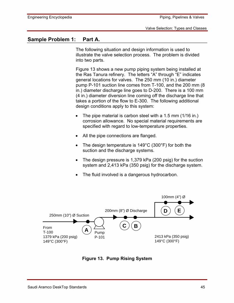
Sample Problem 1: Part A.
The following situation and design information is used to illustrate the valve selection process. The problem is divided into two parts.
Figure 13 shows a new pump piping system being installed at the Ras Tanura refinery. The letters “A” through “E” indicates general locations for valves. The 250 mm (10 in.) diameter pump P-101 suction line comes from T-100, and the 200 mm (8 in.) diameter discharge line goes to D-200. There is a 100 mm (4 in.) diameter diversion line coming off the discharge line that takes a portion of the flow to E-300. The following additional design conditions apply to this system:
• The pipe material is carbon steel with a 1.5 mm (1/16 in.) corrosion allowance. No special material requirements are specified with regard to low-temperature properties.
• All the pipe connections are flanged.
• The design temperature is 149°C (300°F) for both the suction and the discharge systems.
• The design pressure is 1,379 kPa (200 psig) for the suction system and 2,413 kPa (350 psig) for the discharge system.
• The fluid involved is a dangerous hydrocarbon.
AC B
D E
PumpP-101
FromT-1001379 kPa (200 psig)149°C (300°F)
250mm (10") Ø Suction
100mm (4") Ø
200mm (8") Ø Discharge
2413 kPa (350 psig)149°C (300°F)
Figure 13. Pump Rising System
Engineering Encyclopedia Piping, Pipelines & Valves
Valve Selection: Types and Classes
Saudi Aramco DeskTop Standards 46
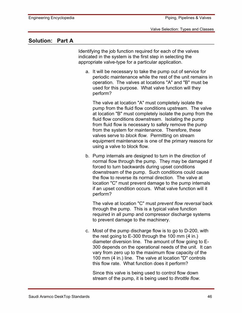
Solution: Part A
Identifying the job function required for each of the valves indicated in the system is the first step in selecting the appropriate valve-type for a particular application.
a. It will be necessary to take the pump out of service for periodic maintenance while the rest of the unit remains in operation. The valves at locations "A" and "B" must be used for this purpose. What valve function will they perform?
The valve at location "A" must completely isolate the pump from the fluid flow conditions upstream. The valve at location "B" must completely isolate the pump from the fluid flow conditions downstream. Isolating the pump from fluid flow is necessary to safely remove the pump from the system for maintenance. Therefore, these valves serve to block flow. Permitting on stream equipment maintenance is one of the primary reasons for using a valve to block flow.
b. Pump internals are designed to turn in the direction of normal flow through the pump. They may be damaged if forced to turn backwards during upset conditions downstream of the pump. Such conditions could cause the flow to reverse its normal direction. The valve at location "C" must prevent damage to the pump internals if an upset condition occurs. What valve function will it perform?
The valve at location "C" must prevent flow reversal back through the pump. This is a typical valve function required in all pump and compressor discharge systems to prevent damage to the machinery.
c. Most of the pump discharge flow is to go to D-200, with
the rest going to E-300 through the 100 mm (4 in.) diameter diversion line. The amount of flow going to E-300 depends on the operational needs of the unit. It can vary from zero up to the maximum flow capacity of the 100 mm (4 in.) line. The valve at location "D" controls this flow rate. What function does it perform?
Since this valve is being used to control flow down stream of the pump, it is being used to throttle flow.
Engineering Encyclopedia Piping, Pipelines & Valves
Valve Selection: Types and Classes
Saudi Aramco DeskTop Standards 47
d. Another valve is in the diversion line at location "E." There are situations when it is necessary to completely isolate the system, in the vicinity of E-300, from the P-101/D-200 system. This need arises when a different fluid is being used in the E-300 system, and it is necessary to prevent mixing of the two fluids. The valve at location "E" serves this purpose. What function does the valve perform?
This is another example of a valve being used to block flow. In this case, equipment is not being taken out of service with the piping being opened to the atmosphere. Instead, a piping system is being divided to perform two separate functions with different fluids. The valve is being used to block the mixing of the two fluids.
Engineering Encyclopedia Piping, Pipelines & Valves
Valve Selection: Types and Classes
Saudi Aramco DeskTop Standards 48
Sample Problem 1: Part B
This problem will now be continued to select appropriate valve-types for the valves at locations "A" through "E." Use Work Aid 1 and the information previously discussed to help solve this problem. The following additional information is provided to aid in this selection process:
• The change in service that requires the block valve at location "E" will sometimes occur very quickly. Thus, separation between the two systems must be accomplished as quickly as possible. In addition, shutoff must be bubble-tight so that the two fluids do not mix.
• The throttling valve at location "D" does not need to have any tight shutoff capability, because the valve at "E" serves that function.
• The block valves at "A" and "B" do not require bubble-tight shutoff or especially quick functioning.
• The maintenance staff at the refinery is very small. Every effort is made to use low-maintenance equipment when available.
• The total pump piping system consists of two pumps in parallel, P-101A and P-101B. Only one of the two pumps is in operation at any one time, thus providing a spare to permit maintenance on the other.
What valve types should be used at locations "A" through "E?"
Engineering Encyclopedia Piping, Pipelines & Valves
Valve Selection: Types and Classes
Saudi Aramco DeskTop Standards 49
Solution: Part B
Locations "A" and "B"
Referring to Work Aid 1, most of the possible block valve-types can be eliminated from consideration.
• All of the soft-seat and quarter-turn valves can be immediately eliminated because these locations do not require those features.
• The through-conduit gate valve is eliminated because this is not a pipeline service.
• The globe valve is eliminated because no throttling is required.
• The nonlubricated plug valve is eliminated because it should be considered for inherently safe services only.
With the above elimination’s, the selection has been narrowed down to a wedge-gate and a lubricated plug valve. Since a lubricated plug valve requires more maintenance to function properly (i.e., periodic addition of lubricant), a wedge-gate valve should be used.
Location "C"
Referring to Work Aid 1, both lift and ball check valves can be eliminated because they are typically available only in sizes of up to 50 mm (2 in.) in diameter. This leaves the swing check and dual-plate wafer check valves to choose from.
SAES-L-008 requires using a non-slam type check valve at the discharge of pumps or compressors that are in a parallel flow arrangement. Because of the spare pump arrangement, this is a parallel flow situation. This eliminates the dual-plate wafer check valve because of its spring-assisted closure. Therefore, a swing check valve should be used.
Engineering Encyclopedia Piping, Pipelines & Valves
Valve Selection: Types and Classes
Saudi Aramco DeskTop Standards 50
Location "D"
Referring to Work Aid 1, the rubber-lined butterfly valve may be eliminated because this is not a water service. That leaves either the soft-seat or metal-seat butterfly valves, or the globe valve as likely candidates.
The soft-seat butterfly valve can be eliminated since bubble-tight shutoff is not a requirement. Therefore, the metal-seat butterfly valve and the globe valve are the only potential candidates. At this point, the choice between the two valves must be based on cost and pressure drop considerations. Further information regarding the flow characteristics of the two valves, pressure drop limitations in the system, and valve cost is required to make the final selection. This information can be obtained from process engineers and the valve vendors. The metal-seated, wafer-type butterfly valve will probably have the lower cost and pressure drop, and will probably be the ultimate choice.
Location "E"
Referring to Work Aid 1, because of the requirements for quick, bubble-tight shutoff, only the quarter-turn valves can be considered for this location.
• The rubber-lined butterfly valve is eliminated because it is not water service.
• The nonlubricated plug valve is eliminated because tight shutoff is not possible with this valve type.
• The lubricated plug valve is eliminated because of maintenance considerations.
These eliminations limit the choice to the soft-seat ball, soft-seat plug, or soft-seat butterfly valves. However, the choice cannot be narrowed to a single selection without additional information. Factors including relative cost, standardization, and availability must be considered before making the final selection.
Engineering Encyclopedia Piping, Pipelines & Valves
Valve Selection: Types and Classes
Saudi Aramco DeskTop Standards 51
Once the particular valve-type is selected, choices among available components and design details must be made as appropriate. Further discussion of this aspect of valve selection is beyond the scope of this course. Participants are referred to the earlier discussions covering valve components, and the checklist contained in Work Aid 1, for additional guidance.
Determining the Required Valve Class and Associated MAOP
After a valve is selected, the rating class and MAOP must be determined. A valve is not completely specified until its class is also specified. The rating class must be supplied to the vendor. As discussed with flanges and fittings in MEX 101.04, pressure/temperature-rating tables will be used to determine valve class. However, in the case of valves, ASME/ANSI B16.34, Valves - Flanged, Threaded, and Welding End, will be used.
This section will discuss the selection of the appropriate pressure/temperature rating class for valves.
Class is based on pressure, temperature, and material, and is determined in accordance with pressure/temperature rating tables, the material group, and design temperature and pressure. The approach is analogous to that used for flanges and flanged fittings, discussed in MEX 101.04. Selecting class sets all the detailed dimensions for valves within the scope of ASME/ANSI B16.34. The objective is to select the lowest class appropriate for the design conditions.
ASME/ANSI B16.34 applies to new valve construction and covers pressure/temperature ratings, dimensions, tolerances, material, nondestructive examination requirements, testing, and marking for cast, forged, and fabricated flanged, threaded, and welding-end, and wafer or flangeless valves of steel, nickel-base alloys, and other alloys.
• ASME/ANSI B16.34 contains eight designated classes: 150, 300, 400, 600, 900, 1500, 2500, and 4500.
• Each class specifies the design pressure and temperature combinations that are acceptable for a valve having that designation.
Engineering Encyclopedia Piping, Pipelines & Valves
Valve Selection: Types and Classes
Saudi Aramco DeskTop Standards 52
• As the number of the class increases, the strength of the valve increases. Therefore, higher valve classes can withstand higher pressure/temperature combinations.
• As the number of the class increases, the cost of the valve
also increases because more material is being used to make the higher class stronger. Therefore, there is an economic incentive to use the lowest class that will meet the design requirements.
• Each of the valve material groups has a table in ASME/ANSI B16.34 that provides the ratings for that group. Figure 14 is a list of material specifications, and Table 2 is for Group 1.1 materials. Note that all pressure classes are in the one table.
• Valve flange-type must match pipe flange-type.
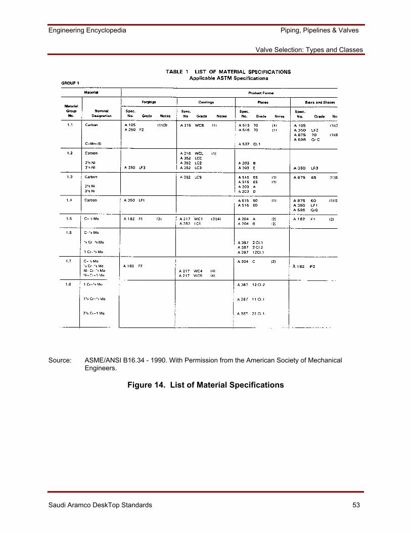
Engineering Encyclopedia Piping, Pipelines & Valves
Valve Selection: Types and Classes
Saudi Aramco DeskTop Standards 53
Source: ASME/ANSI B16.34 - 1990. With Permission from the American Society of Mechanical Engineers.
Figure 14. List of Material Specifications
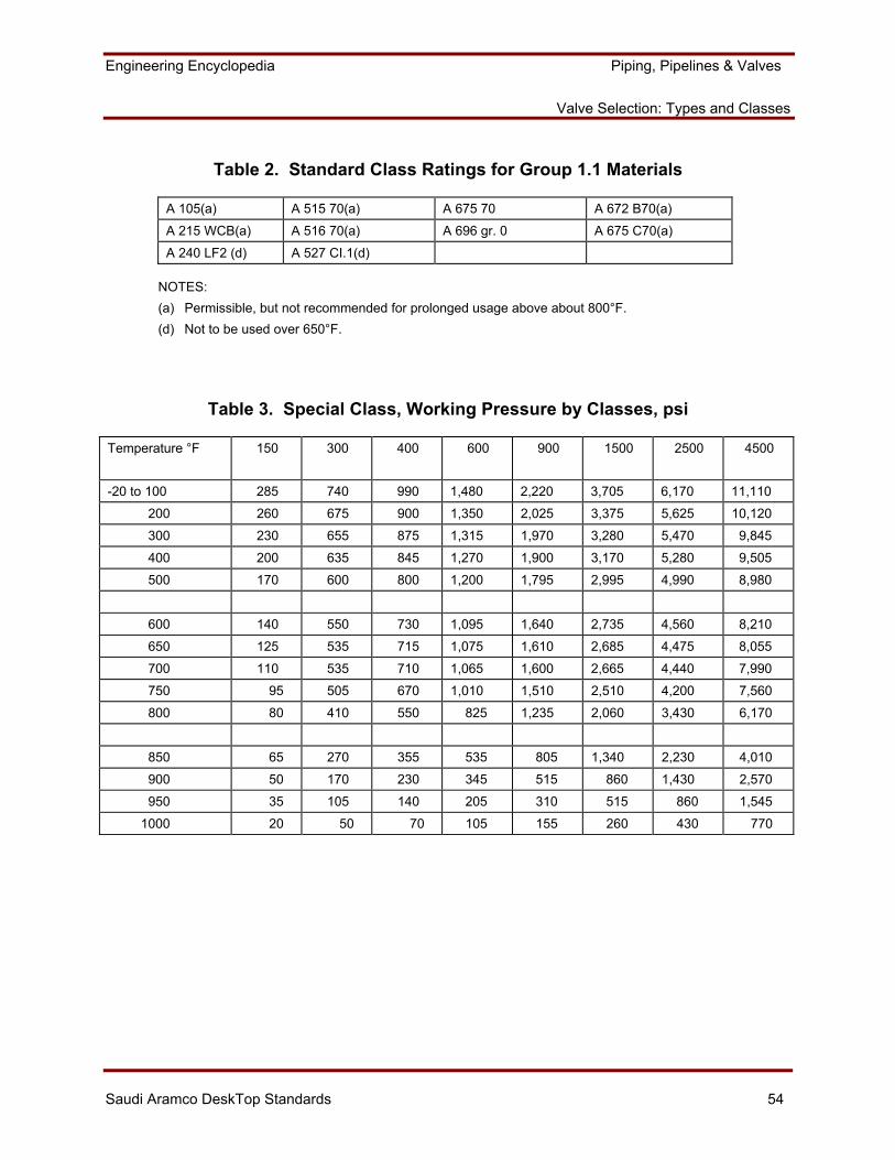
Engineering Encyclopedia Piping, Pipelines & Valves
Valve Selection: Types and Classes
Saudi Aramco DeskTop Standards 54
Table 2. Standard Class Ratings for Group 1.1 Materials
A 105(a) A 515 70(a) A 675 70 A 672 B70(a)
A 215 WCB(a) A 516 70(a) A 696 gr. 0 A 675 C70(a)
A 240 LF2 (d) A 527 CI.1(d)
NOTES: (a) Permissible, but not recommended for prolonged usage above about 800°F. (d) Not to be used over 650°F.
Table 3. Special Class, Working Pressure by Classes, psi
Temperature °F 150 300 400 600 900 1500 2500 4500
-20 to 100 285 740 990 1,480 2,220 3,705 6,170 11,110
200 260 675 900 1,350 2,025 3,375 5,625 10,120
300 230 655 875 1,315 1,970 3,280 5,470 9,845
400 200 635 845 1,270 1,900 3,170 5,280 9,505
500 170 600 800 1,200 1,795 2,995 4,990 8,980
600 140 550 730 1,095 1,640 2,735 4,560 8,210
650 125 535 715 1,075 1,610 2,685 4,475 8,055
700 110 535 710 1,065 1,600 2,665 4,440 7,990
750 95 505 670 1,010 1,510 2,510 4,200 7,560
800 80 410 550 825 1,235 2,060 3,430 6,170
850 65 270 355 535 805 1,340 2,230 4,010
900 50 170 230 345 515 860 1,430 2,570
950 35 105 140 205 310 515 860 1,545
1000 20 50 70 105 155 260 430 770
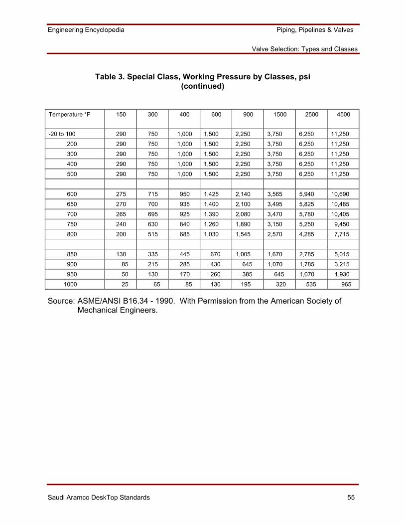
Engineering Encyclopedia Piping, Pipelines & Valves
Valve Selection: Types and Classes
Saudi Aramco DeskTop Standards 55
Table 3. Special Class, Working Pressure by Classes, psi (continued)
Temperature °F 150 300 400 600 900 1500 2500 4500
-20 to 100 290 750 1,000 1,500 2,250 3,750 6,250 11,250
200 290 750 1,000 1,500 2,250 3,750 6,250 11,250
300 290 750 1,000 1,500 2,250 3,750 6,250 11,250
400 290 750 1,000 1,500 2,250 3,750 6,250 11,250
500 290 750 1,000 1,500 2,250 3,750 6,250 11,250
600 275 715 950 1,425 2,140 3,565 5,940 10,690
650 270 700 935 1,400 2,100 3,495 5,825 10,485
700 265 695 925 1,390 2,080 3,470 5,780 10,405
750 240 630 840 1,260 1,890 3,150 5,250 9,450
800 200 515 685 1,030 1,545 2,570 4,285 7,715
850 130 335 445 670 1,005 1,670 2,785 5,015
900 85 215 285 430 645 1,070 1,785 3,215
950 50 130 170 260 385 645 1,070 1,930
1000 25 65 85 130 195 320 535 965
Source: ASME/ANSI B16.34 - 1990. With Permission from the American Society of Mechanical Engineers.
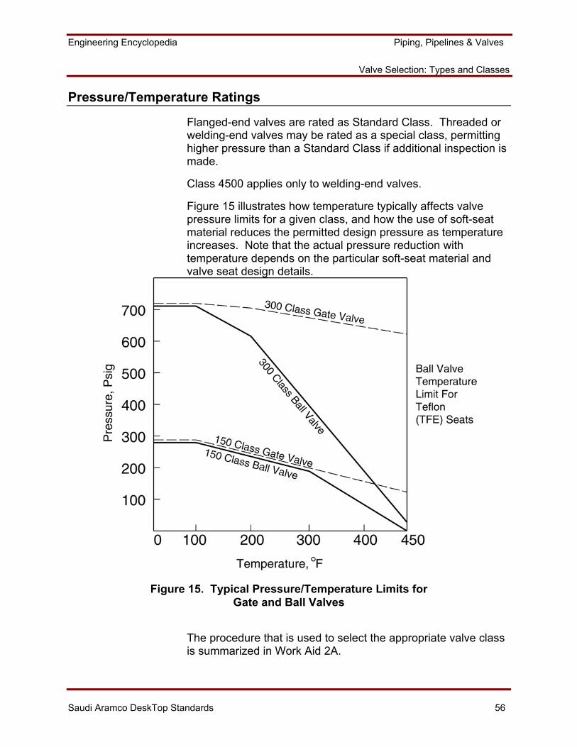
Engineering Encyclopedia Piping, Pipelines & Valves
Valve Selection: Types and Classes
Saudi Aramco DeskTop Standards 56
Pressure/Temperature Ratings
Flanged-end valves are rated as Standard Class. Threaded or welding-end valves may be rated as a special class, permitting higher pressure than a Standard Class if additional inspection is made.
Class 4500 applies only to welding-end valves.
Figure 15 illustrates how temperature typically affects valve pressure limits for a given class, and how the use of soft-seat material reduces the permitted design pressure as temperature increases. Note that the actual pressure reduction with temperature depends on the particular soft-seat material and valve seat design details.
Figure 15. Typical Pressure/Temperature Limits for Gate and Ball Valves
The procedure that is used to select the appropriate valve class is summarized in Work Aid 2A.
Engineering Encyclopedia Piping, Pipelines & Valves
Valve Selection: Types and Classes
Saudi Aramco DeskTop Standards 57
IDENTIFYING VALVE INSPECTION AND TESTING REQUIREMENTS
All valves require a certain degree of inspection and testing before installation and during operation. This is true for both new and reconditioned valves. The engineer generally does not actually perform or witness the tests. He must specify the mandatory tests for vendors to execute. This section reviews the types of inspection and test procedures that are utilized, where they are specified, and when they should be applied.
Requirements for valve inspection and testing are covered in Saudi Aramco Materials System Specification 04-SAMSS-048, Valve Inspection and Testing Requirements. 04-SAMSS-048 references which industry standards apply, plus additional Saudi Aramco requirements.
Several different inspections and testing methods are normally applied to valves. The selection of a particular method is governed by valve material, rating, service conditions, and other considerations. Inspection methods vary from the quick and simple visual inspection of a valve casting and components to more sophisticated radiographic examinations. Test methods may include hydrostatic and/or pneumatic testing of the assembled valve and seats. Impact tests may be required based on the temperature conditions, material, and body thickness.
Material testing ensures that materials that are used in the valve meet material specifications with respect to chemistry, strength, and hardness. Pressure testing ensures the integrity of the valve body and valve seat tightness when closed.
Engineering Encyclopedia Piping, Pipelines & Valves
Valve Selection: Types and Classes
Saudi Aramco DeskTop Standards 58
Minimum Inspection Requirements for New Valves
04-SAMSS-048 requires that, as a minimum, each valve be tested, examined, and qualified per the industry standard referenced in the purchase order and the applicable 04-SAMSS valve specification. Supplementary requirements are contained within 04-SAMSS-048. API 598, Valve Inspection and Testing, is the basic document used for inspection and testing of gate-, globe-, plug-, ball-, check-, and butterfly-type valves. The following highlight requirements that are contained in API 598 and 04-SAMSS-048, plus additional inspection guidelines. Work Aid 2A summarizes overall valve inspection and testing requirements based on 04-SAMSS-048 and API 598.
The minimum inspection required by API 598 is an examination of the valve casting and components. This examination includes a check of all the valve features listed on the purchase order such as size, rating (and wall thickness), end connections material, etc. In addition, when a valve model number has been included in the purchase order, all dimensions should be checked against those shown in the vendor's catalog.
Surface Examination
A visual check of the valve body casting is required to ensure conformance with the minimum casting quality specified by MSS SP-55, Quality Standard for Steel Castings for Valves, Flanges and Fittings and Other Piping Components - Visual Method. The minimum number of available valves of a given style and size to be so inspected at a given time is:
Number Ready Number Examined
10 or less All More than 10 15% (min. of 10) Special All
Special valves are those requiring nondestructive examination of the shell (radiography, magnetic particle, etc.), impact testing of the shell and bolting; motor operators; or of Monel, Hastelloy or aluminum material. If objectionable castings are found, the percent inspected should be doubled. If additional defects are found in these, all the valves should be inspected. This is done to confirm that the valves meet the dimensional requirements of the relevant standards and that the supplied components meet the purchase requirements.
Engineering Encyclopedia Piping, Pipelines & Valves
Valve Selection: Types and Classes
Saudi Aramco DeskTop Standards 59
Dimensional and Component Checks
Dimensional and component checks are conducted at the same time and on about one-half of the valves that are surface examined. Essential dimensions/component features to be checked are:
• The finish on flange faces and ring joints.
• Face-to-face dimension.
• Flange outside diameter, bolt circle diameter, bolt hole diameter, flange thickness.
• Body wall thickness (per applicable standard).
• Bevel preparation on welding-end valves.
• Stem diameter.
• Threaded ends (size and taper, if required).
• Socket-end concentricity and wall thickness (per ANSI B16.11).
• For gate valves, with the gate closed, the position of the gate seat rings relative to the body seat rings to confirm sufficient wear travel position.
• For soft-sealed gate valves, the height of the soft seal above the metal seats, the width of the soft seal, and the total width of the metal seat outside the soft seal.
• Component features as specified in the purchase order (such as stem packing material, bonnet gasket-type, operator-type, soft-seal material, body bleed number, and location).
• Materials identification. Obtain chemical and physical test data on steel and alloy steel castings for all valves inspected. All alloys bolting must be identified by markings required by the specifications on the stud or bolt ends, or on nuts.
• Additional tests conforming to SAMSS requirements, such as hardness or impact testing, may also be required if specified in the purchase order.
Engineering Encyclopedia Piping, Pipelines & Valves
Valve Selection: Types and Classes
Saudi Aramco DeskTop Standards 60
The minimum testing required by API 598 is a pressure test of the shell, back seat (if any), and seats. Test pressures and durations are specified in API 598, based on valve sizes and the type of test. Specific test procedures per API 598 will be discussed.
Shell Test
The Shell Test is conducted first, to assure that any body distortions that result from this high-pressure test will be reflected in subsequent seat tests at lower pressures. This test confirms the basic structural integrity of the valve. Test pressure is to be in accordance with API 598, based on valve material and pressure class. For steel-flanged and butt-welded valves, API 598 requires that test pressures be in accordance with ASME/ANSI B16.34 [1.5 times the 38°C (100°F) rating pressure rounded up to the nearest 172 kPA (25 psig)]. Pressure must be applied across the full bore of the valve, not through a reduced-bore and adapter. The test fluid should preferably be water. While API 598 permits pneumatic testing, this should be allowed only if the inspector has reviewed the test procedures and set-up to be sure that adequate safety precautions are taken. No leakage is permitted during the shell test.
Back Seat Test
The Back Seat Test is conducted after the Shell Test with same test fluid. Test pressure is to be 110% of the pressure rating at 38°C (100°F). The stem is to be fully open (back seated), and the stem packing is to be loose. No leakage is permitted during this test. This test may be conducted in conjunction with the optional high-pressure Closure Test. The purpose of this test is to confirm that the valve stem packing may be removed and reinstalled while the valve is still under system pressure with the stem fully open.
Engineering Encyclopedia Piping, Pipelines & Valves
Valve Selection: Types and Classes
Saudi Aramco DeskTop Standards 61
Low-pressure Closure Test
The low-pressure Closure Test is conducted with air (or inert gas) at 414-690 kPa (60-100 psig). The air discharge is to be slightly below a water surface to facilitate determination of leakage rates. For valves with body bleeds, the test procedure should be per API 598, Paragraph 4.4.2c, and leakage shall be measured through the open bleed. This requires that pressure be applied successively to each side of the closure component, and leakage checked through the open bleed valve. This confirms that each seat seals, which is necessary for block and bleed capability. For valves without body bleeds, the test procedure shall be per API 598, Paragraph 4.4.2a. This requires that pressure be applied successively to each side of the closure components and leakage be checked on the other side. This confirms that leakage across both seats together is acceptable.
For metal-seated valves, allowable leakage rates are as specified in API 598. For soft-sealed valves, no leakage is permitted during this test. The low-pressure Closure Test is mandatory for gate, plug, floating ball, trunnion-mounted metal-seated ball, and metal-seated butterfly valves, per API 598. It may be used as an alternative to the high-pressure Closure Test, described below, for check valves. The low-pressure Closure Test is optional for globe, soft-seated butterfly, and soft-seated trunnion mounted ball valves.
High-pressure Closure Test
The high-pressure Closure Test is conducted after the Shell Test with the same test fluid. The test pressure required depends on the valve-type as follows:
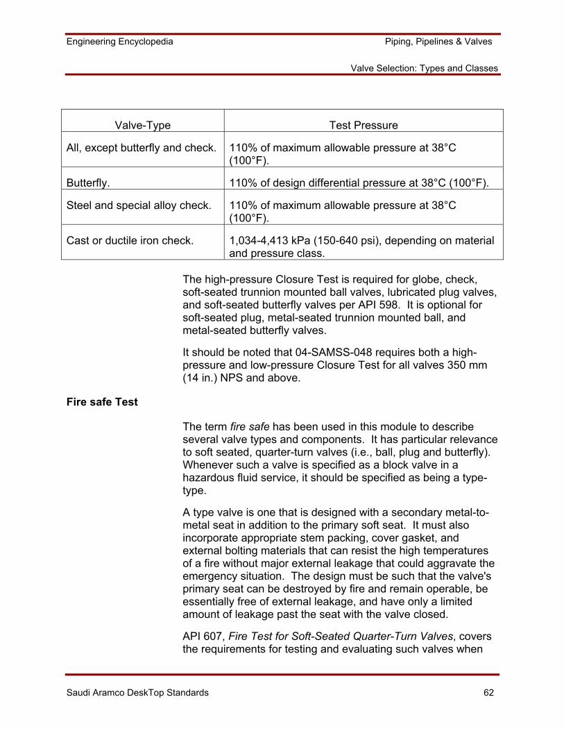
Engineering Encyclopedia Piping, Pipelines & Valves
Valve Selection: Types and Classes
Saudi Aramco DeskTop Standards 62
Valve-Type Test Pressure
All, except butterfly and check. 110% of maximum allowable pressure at 38°C (100°F).
Butterfly. 110% of design differential pressure at 38°C (100°F).
Steel and special alloy check. 110% of maximum allowable pressure at 38°C (100°F).
Cast or ductile iron check. 1,034-4,413 kPa (150-640 psi), depending on material and pressure class.
The high-pressure Closure Test is required for globe, check, soft-seated trunnion mounted ball valves, lubricated plug valves, and soft-seated butterfly valves per API 598. It is optional for soft-seated plug, metal-seated trunnion mounted ball, and metal-seated butterfly valves.
It should be noted that 04-SAMSS-048 requires both a high-pressure and low-pressure Closure Test for all valves 350 mm (14 in.) NPS and above.
Fire safe Test
The term fire safe has been used in this module to describe several valve types and components. It has particular relevance to soft seated, quarter-turn valves (i.e., ball, plug and butterfly). Whenever such a valve is specified as a block valve in a hazardous fluid service, it should be specified as being a type-type.
A type valve is one that is designed with a secondary metal-to-metal seat in addition to the primary soft seat. It must also incorporate appropriate stem packing, cover gasket, and external bolting materials that can resist the high temperatures of a fire without major external leakage that could aggravate the emergency situation. The design must be such that the valve's primary seat can be destroyed by fire and remain operable, be essentially free of external leakage, and have only a limited amount of leakage past the seat with the valve closed.
API 607, Fire Test for Soft-Seated Quarter-Turn Valves, covers the requirements for testing and evaluating such valves when
Engineering Encyclopedia Piping, Pipelines & Valves
Valve Selection: Types and Classes
Saudi Aramco DeskTop Standards 63
exposed to a fire. Its use is specified by SAES-L-008, Selection of Valves. SAES-L008 also permits fire testing in accordance with API RP 6F, Recommended Practice for Fire Test for Valves, or BS 5146, Inspection and Testing for Steel Valves.
API 607 specifies the details of the fire test apparatus and procedure (which involves enveloping the valve in a flame), test pressures during and after the fire, and acceptable seat and external leakage. When a valve design passes the specified testing, it may be certified as fire tested per API 607.
Other Inspection Considerations
When 04-SAMSS-003, Additional Requirements for Low-Temperature Valves, is specified in the purchase order, additional valve material impact testing or other requirements may be necessary. 04-SAMSS-003 covers additional requirements for steel valves in services with minimum design temperatures between 0 and -45°C (32 and -50°F). If the valve materials comply with material specifications noted in 04-SAMSS-003, no additional impact testing is required. If the materials do not comply with those specified, then impact testing per ASME/ANSI B31.3 is required with acceptance criteria as stated in 04-SAMSS-003. Several other requirements with respect to nonmetallic materials, design details and marking are also included.
The ASME/ANSI B16.34 ratings include a Special Class category applicable to threaded and butt-welding end valves only. The Special Class pressure/temperature ratings generally exceed those in the Standard Class for each pressure class rating, but supplementary nondestructive examination (NDE) of valve bodies and bonnets is required to qualify valves for the Special Class category. The supplementary NDE requirements consists of a radiographic examination of critical areas, and 100% magnetic particle or liquid penetrant examination, for each valve body and bonnet of any construction, (i.e., cast, forged, fabricated, etc.). This supplementary inspection confirms the valve body and bonnet to be a higher quality, and thus permits using higher maximum allowable design pressures than for the standard class.
Engineering Encyclopedia Piping, Pipelines & Valves
Valve Selection: Types and Classes
Saudi Aramco DeskTop Standards 64
SUMMARY
Valves are major components of a piping system and require careful attention during the design process. Selecting a valve is based upon the required valve function: to block flow, throttle flow, or prevent flow reversal. There are numerous types of valves. The valve most commonly used (approximately 75% of the time) is the gate valve. SAES-L-008 provides special service limitations and selection requirements for valves. The 04-SAMSS-series of specifications provides additional valve design requirements. Once a valve is selected, its flange rating class must be specified based on its design pressure/temperature and the MAOP of the class. Finally, the valve must be inspected and tested.
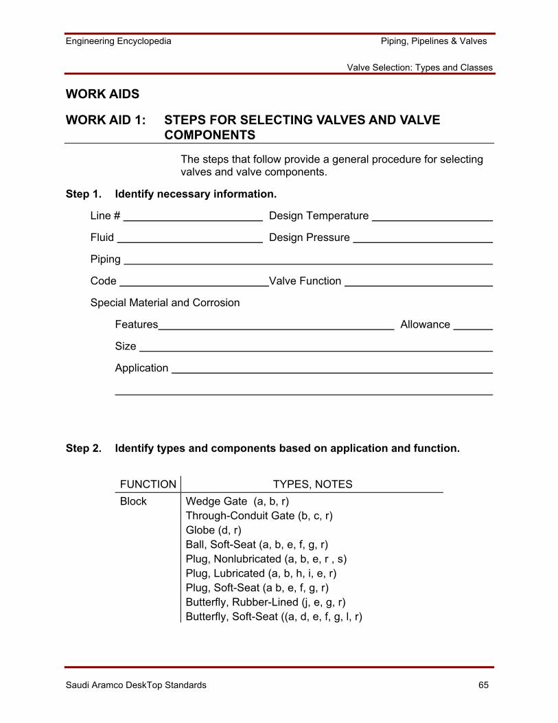
Engineering Encyclopedia Piping, Pipelines & Valves
Valve Selection: Types and Classes
Saudi Aramco DeskTop Standards 65
WORK AIDS
WORK AID 1: STEPS FOR SELECTING VALVES AND VALVE COMPONENTS
The steps that follow provide a general procedure for selecting valves and valve components.
Step 1. Identify necessary information.
Line # Design Temperature
Fluid Design Pressure
Piping
Code Valve Function
Special Material and Corrosion
Features Allowance
Size
Application
Step 2. Identify types and components based on application and function.
FUNCTION TYPES, NOTES Block Wedge Gate (a, b, r)
Through-Conduit Gate (b, c, r) Globe (d, r) Ball, Soft-Seat (a, b, e, f, g, r) Plug, Nonlubricated (a, b, e, r , s) Plug, Lubricated (a, b, h, i, e, r) Plug, Soft-Seat (a b, e, f, g, r) Butterfly, Rubber-Lined (j, e, g, r) Butterfly, Soft-Seat ((a, d, e, f, g, l, r)
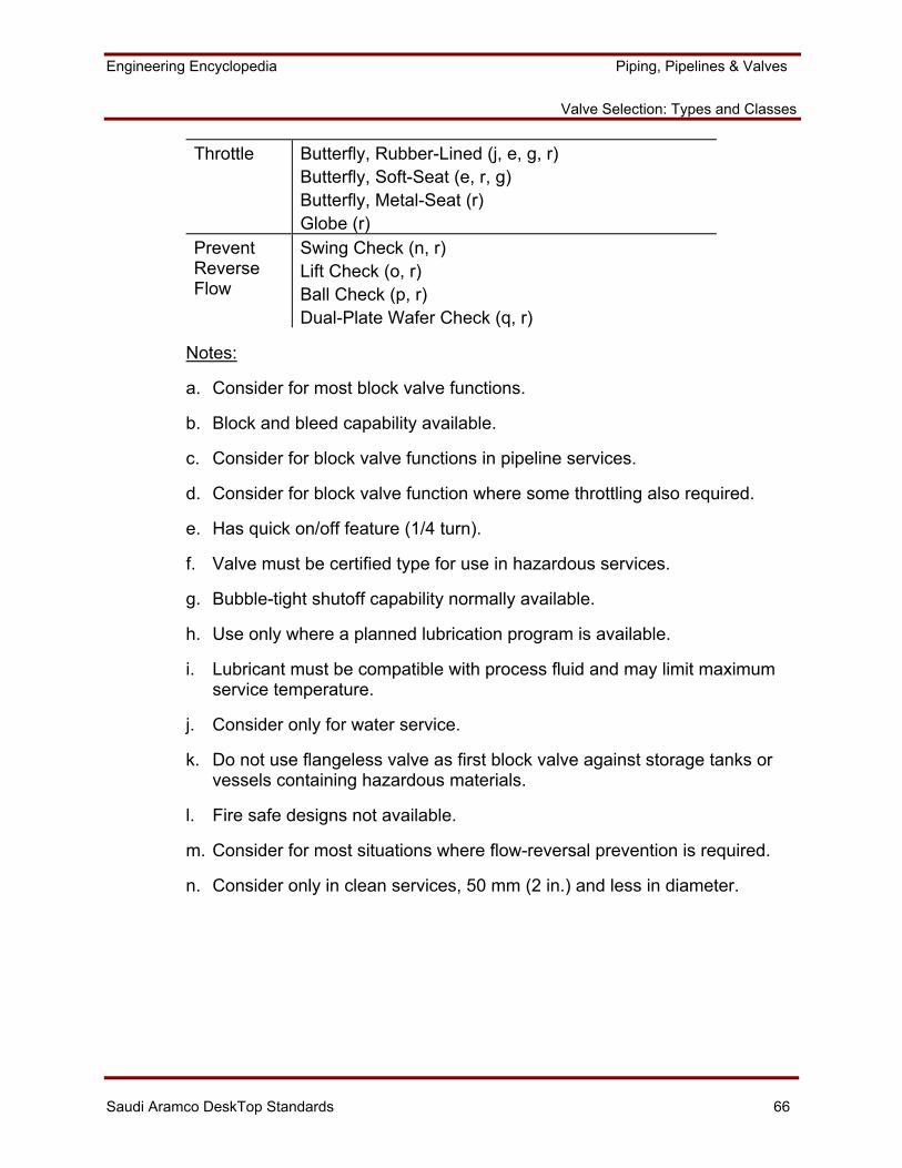
Engineering Encyclopedia Piping, Pipelines & Valves
Valve Selection: Types and Classes
Saudi Aramco DeskTop Standards 66
Throttle Butterfly, Rubber-Lined (j, e, g, r) Butterfly, Soft-Seat (e, r, g) Butterfly, Metal-Seat (r) Globe (r)
Prevent Reverse Flow
Swing Check (n, r) Lift Check (o, r) Ball Check (p, r) Dual-Plate Wafer Check (q, r)
Notes:
a. Consider for most block valve functions.
b. Block and bleed capability available.
c. Consider for block valve functions in pipeline services.
d. Consider for block valve function where some throttling also required.
e. Has quick on/off feature (1/4 turn).
f. Valve must be certified type for use in hazardous services.
g. Bubble-tight shutoff capability normally available.
h. Use only where a planned lubrication program is available.
i. Lubricant must be compatible with process fluid and may limit maximum service temperature.
j. Consider only for water service.
k. Do not use flangeless valve as first block valve against storage tanks or vessels containing hazardous materials.
l. Fire safe designs not available.
m. Consider for most situations where flow-reversal prevention is required.
n. Consider only in clean services, 50 mm (2 in.) and less in diameter.
Engineering Encyclopedia Piping, Pipelines & Valves
Valve Selection: Types and Classes
Saudi Aramco DeskTop Standards 67
o. Consider only where pressure drop is not a concern, 50 mm (2 in.) and less in diameter.
p. Do not use in pulsating services, such as reciprocating pump or compressor systems.
q. See SAES-L-008 for additional limitations.
r. Consider only for inherently safe services, or where tight shutoff is not required.
Possible Type(s)
Step 3. Determine requirements.
Design or service limitations specified in SAES-L-008:
Step 4. Finalize selection.
Check which factors need consideration if two or more valves are suitable.
[ ] Standardization
[ ] Inventory
[ ] Experience
[ ] Cost
[ ] Delivery Time
[ ] Materials
[ ] Dimensions
Engineering Encyclopedia Piping, Pipelines & Valves
Valve Selection: Types and Classes
Saudi Aramco DeskTop Standards 68
Step 5. Provide a full description.
For example, a metal-seat gate valve.
Specify the following:
Type:
Material:
Flange Rating:
Major Components (specify if necessary):
End Connections (flanged, threaded, socket-welded, butt-welded, wafer)
Trim (See SAES-L-008)
Body Pattern (i.e., venturi-, reduced-port, full-port)
Bonnet (i.e., bolted, screwed)
Stem (i.e., OS&Y, rising stem/inside screw)
Seat (i.e., metal, soft, see SAES-L-008)
Stem Packing System (See SAES-L-008)
Bonnet Gasket (See SAES-L-008, and gasket specified for pipe flanges)
Applicable SAMSS's that needs to be attached to purchase order:
04-SAMSS-035 and 04-SAMSS-048 for all valves
04-SAMSS-003 for all valves with a minimum design temperature between 0°C and -46°C (32°F and -50°F)
04-SAMSS’s applicable to specific valve-type, if available
Engineering Encyclopedia Piping, Pipelines & Valves
Valve Selection: Types and Classes
Saudi Aramco DeskTop Standards 69
WORK AID 2: Procedure for Determining Valve Class, MAOP, and Appropriate Test Type
The procedure that follows is used to select the appropriate valve class and MAOP based on ASME/ANSI B16.34.
1. Select generic valve material based on pipe material and SAES-L-008, and refer to Table 1 of ASME/ANSI B31.34 (excerpt in Figure 17). Are any special pipe material characteristics required for the service? For example, is a low-temperature grade of carbon steel being used?
2. From the generic valve material, determine what product form the valve is in: forgings, castings, plates, bars and shapes, tubular products. Typically, valves 50 mm (2 in.) in diameter or less are forgings. Larger valves are castings. Plates and tubular products are used only for fabricated valves.
3. Select the Material Group Number that corresponds to the closest match between the valve and pipe materials for the required valve product form. Material Group 1.1 will typically be appropriate for carbon steel valves that are used by Saudi Aramco.
4. Refer to Table 2 of ASME/ANSI B31.34 for the Material Group Number selected (excerpt in Figure 28).
- Valve Class is read across the top of the table.
- Valve design temperature is read down the left side of the table.
- The numbers in the table are the maximum allowable valve design pressures (MAOP) for a particular combination of valve class and design temperature.
- Use linear interpolation for design temperatures located between the values listed.
5. Ensure that the specified pipe design pressure is encompassed by the acceptable pressure/temperature rating combinations of a given class. Proceed to progressively higher class until the correct one is found for the design conditions.
6. Use Standard Class unless the valves are butt-welded ends and additional inspection corresponding to Special Class requirements has been specified.
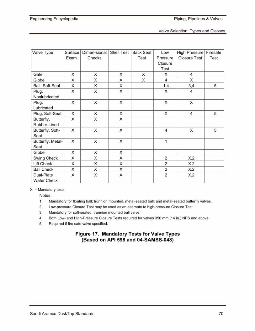
Engineering Encyclopedia Piping, Pipelines & Valves
Valve Selection: Types and Classes
Saudi Aramco DeskTop Standards 70
Valve Type Surface
Exam. Dimen-sional
Checks Shell Test Back Seat
Test Low
Pressure Closure
Test
High Pressure Closure Test
Firesafe Test
Gate X X X X X 4 Globe X X X X 4 X Ball, Soft-Seal X X X 1,4 3,4 5 Plug, Nonlubricated
X X X X 4
Plug, Lubricated
X X X X X
Plug, Soft-Seat X X X X 4 5 Butterfly, Rubber-Lined
X X X
Butterfly, Soft-Seat
X X X 4 X 5
Butterfly, Metal-Seat
X X X 1
Globe X X X Swing Check X X X 2 X,2 Lift Check X X X 2 X.2 Ball Check X X X 2 X.2 Dual-Plate Wafer Check
X X X 2 X.2
X = Mandatory tests. Notes: 1. Mandatory for floating ball; trunnion mounted, metal-seated ball; and metal-seated butterfly valves. 2. Low-pressure Closure Test may be used as an alternate to high-pressure Closure Test. 3. Mandatory for soft-seated, trunnion mounted ball valve. 4. Both Low- and High-Pressure Closure Tests required for valves 350 mm (14 in.) NPS and above. 5. Required if fire safe valve specified.
Figure 17. Mandatory Tests for Valve Types (Based on API 598 and 04-SAMSS-048)