Embed Size (px)
Citation preview
ValvesWahler – Solutions in Partnership.Products for Exhaust Gas and Temperature Management.
2 3
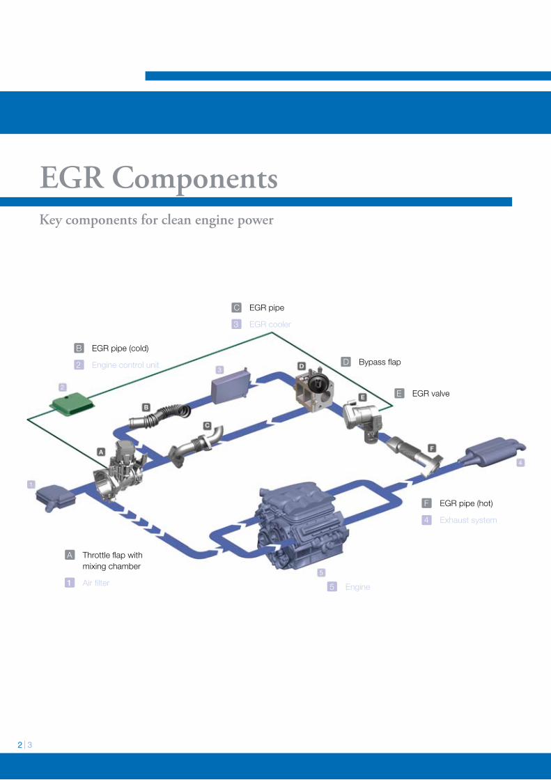
EGR ComponentsKey components for clean engine power
A Throttle flap with mixing chamber
1 Air filter
B EGR pipe (cold)
2 Engine control unit
C EGR pipe
3 EGR cooler
F EGR pipe (hot)
4 Exhaust system
5 Engine
D Bypass flap
E EGR valve
1992 1993 1994 1995 1996 1997 1998 1999 2000 2001 2002 2003 2004 2005 2006 2007 2008 2009 2010
PneumatischesAGR-Ventil
Euro I Euro II Euro III Euro IV Euro V
ElektrischesAGR-Ventil
mit Elektronik
ElektrischesAGR-Ventilohne Elektronik
ElektrischesAGR-Ventilmit DC-Antrieb
ElektrischesAGR-Klappenventilmit Elektronik
ElektrischesAGR-Drehventilmit Elektronik
ElektrischeDrosselklappemit Elektronik
Entwicklung der Euro-Normen und der Wahler-AGR-Komponenten
NOx 1000
180 80 / 100* 50 25
800 500 250
5
180
PM
Werte in mg/km * mit Direkteinspritzung
0
Partikel, ungekühlt
Partikel, gekühlt
NOx, ungekühlt
NOx, gekühlt
10 20 30 40 50 60 70
Emis
sion
AGR-Rate in [%]
0
0
Klappenventil
Hubventil
Drehventil
120
>200
Durchsatzkennlinien
Hubventil
Klappen-/Drehventil
max Hub
90°
s [mm]
ϕ [ ]
Q [kg/h]bei 100 hPa
The demands made on driving comfort
and engine power are constantly
increasing. At the same time a growing
awareness of the environment and more
stringent exhaust gas limit values
world-wide demand reduced emissions
of hazardous substances, particularly of
nitric oxide and particle distributions.
EGR for reducing NOxThe most effective method for reducing
the share of nitric oxides (NOx) is
achieved by exhaust gas return (EGR).
Here, the exhaust gas is mixed with the
sucked-in ambient air. This leads to a
lower oxygen concentration in the air/fuel
mixture for the same load quantity in the
combustion chamber, and thus to slower
combustion. The subsequently achieved
reduction in the peak combustion
temperatures results in the reduced
formation of nitric oxide.
The reduced combustion temperature
leads to an increase in the particle
distribution in diesel engines. Post-oxida-
tion of the particles and their complete
burn-out would only take place at high
temperatures. A conflict of objectives with
the technical term ‘Trade-Off’.
EGR Systems
The combustion under differing operating
conditions of the engine is always kept
within the optimum working range via
respective functions of the engine control
unit and the implementation of EGR
systems.
The EGR valve enables the quantity of the
recirculated exhaust gas to be regulated.
Depending on the engine temperature, the
exhaust gas can be conducted through
the bypass flap via the EGR cooler, or to
the mixing chamber, uncooled. The throttle
flap in the intake channel allows the
differential pressure to rise and thereby
the EGR quantity to increase.
The figure on the left shows all the EGR
components that complement each
other due to Wahler's close collaboration
with the engine manufacturers to form a
perfectly adapted EGR system. The
implementation of EGR systems in the
engines of the future will continue to
increase, in order to adhere to the
emission standards that are continually
becoming more and more stringent.
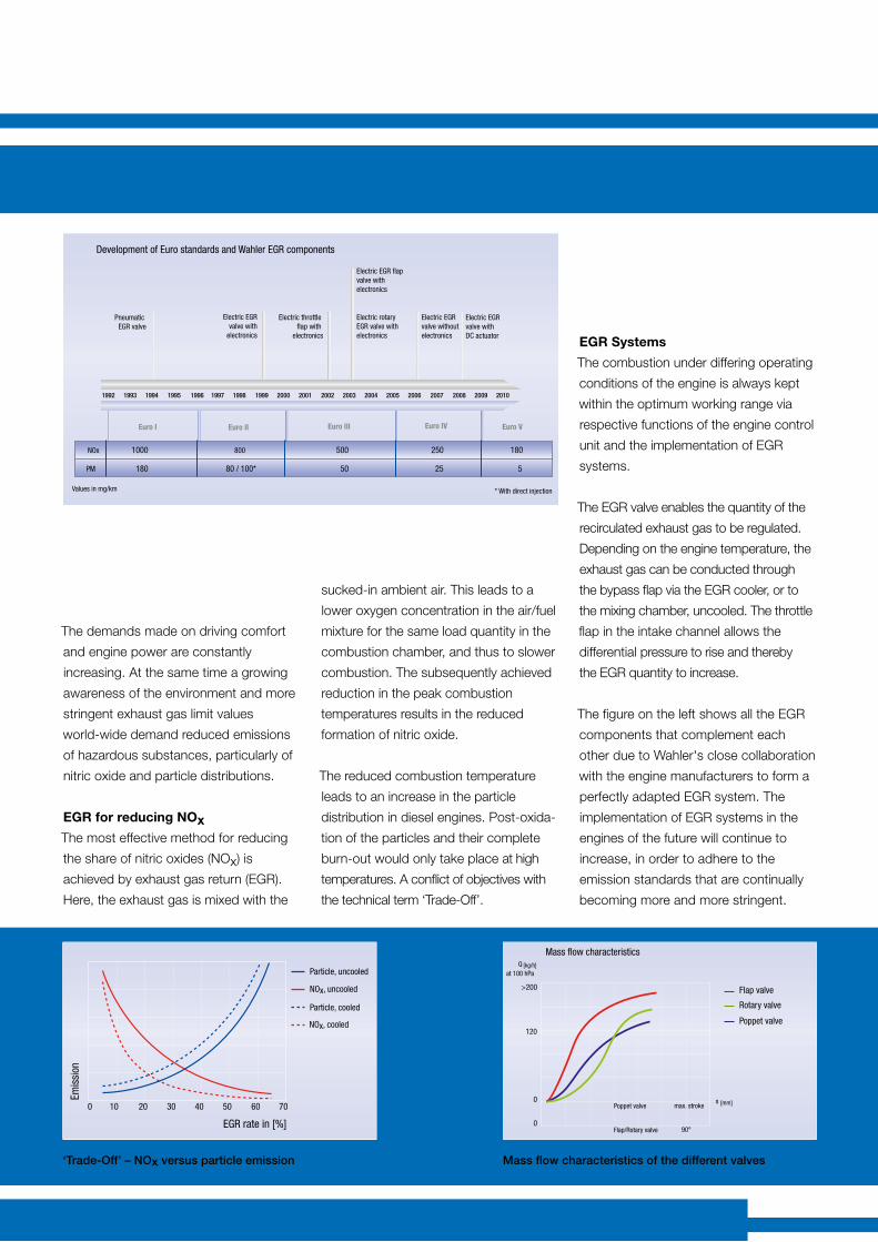
‘Trade-Off’ – NOx versus particle emission Mass flow characteristics of the different valves
1992 1993 1994 1995 1996 1997 1998 1999 2000 2001 2002 2003 2004 2005 2006 2007 2008 2009 2010
Pneumatic EGR valve
Euro I Euro II Euro III Euro IV Euro V
Electric EGRvalve with
electronics
Electric EGR valve without electronics
Electric EGR valve with DC actuator
Electric EGR flap valve with electronics
Electric rotary EGR valve with electronics
Electric throttle flap with
electronics
Development of Euro standards and Wahler EGR components
NOx 1000
180 80 / 100* 50 25
800 500 250
5
180
PM
Values in mg/km * With direct injection
0
Particle, uncooled
Particle, cooled
NOx, uncooled
NOx, cooled
10 20 30 40 50 60 70
Emis
sion
EGR rate in [%]
0
0
Flap valve
Poppet valve
Rotary valve
120
>200
Mass flow characteristics
Poppet valve max. strokes [mm]
Q [kg/h]at 100 hPa
Flap/Rotary valve 90°
4 5
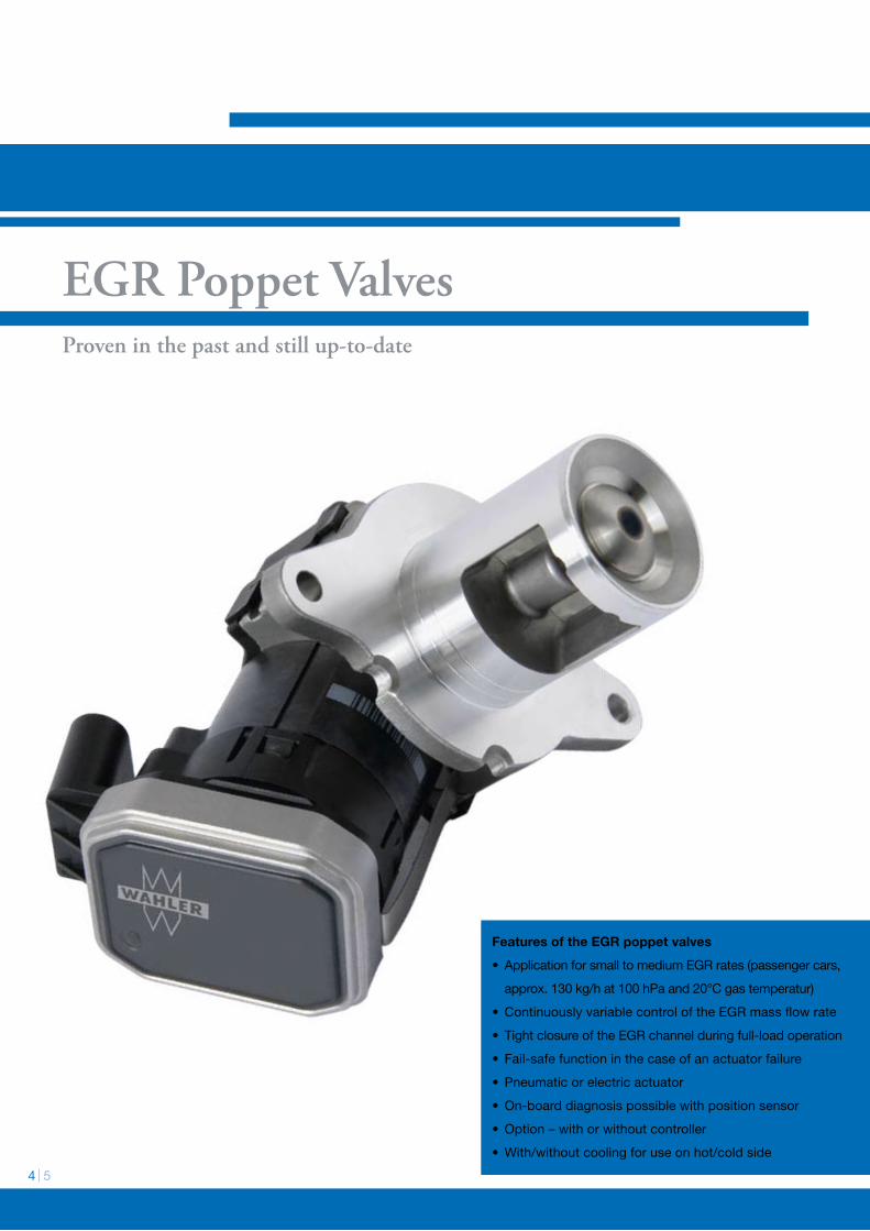
EGR Poppet ValvesProven in the past and still up-to-date
Features of the EGR poppet valves
• ApplicationforsmalltomediumEGRrates(passengercars,
approx.130kg/hat100hPaand20°Cgastemperatur)
• ContinuouslyvariablecontroloftheEGRmassflowrate
• TightclosureoftheEGRchannelduringfull-loadoperation
• Fail-safefunctioninthecaseofanactuatorfailure
• Pneumaticorelectricactuator
•On-boarddiagnosispossiblewithpositionsensor
•Option–withorwithoutcontroller
•With/withoutcoolingforuseonhot/coldside
Vergleich Aktuatortypen
pneumatisch
elektrisch
Wahler was one of the first to realise the
significance of exhaust gas return and
played a decisive role in its development.
Since 1994 we have been producing pneu-
matic EGR valves in series and the figures
speak for themselves. Over 10 million
poppet valves have since been regulating
the flow of exhaust gas in the engines of
the most varying manufacturers.
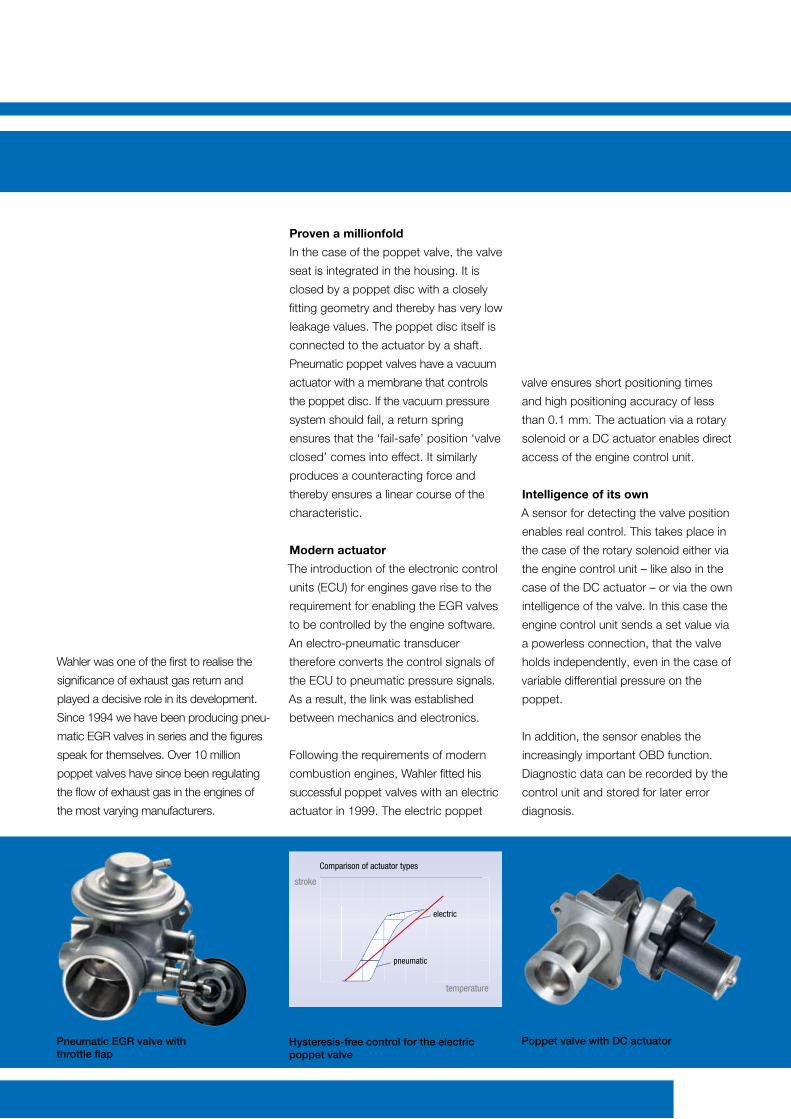
Proven a millionfold
In the case of the poppet valve, the valve
seat is integrated in the housing. It is
closed by a poppet disc with a closely
fitting geometry and thereby has very low
leakage values. The poppet disc itself is
connected to the actuator by a shaft.
Pneumatic poppet valves have a vacuum
actuator with a membrane that controls
the poppet disc. If the vacuum pressure
system should fail, a return spring
ensures that the ‘fail-safe’ position ‘valve
closed’ comes into effect. It similarly
produces a counteracting force and
thereby ensures a linear course of the
characteristic.
Modern actuator
The introduction of the electronic control
units (ECU) for engines gave rise to the
requirement for enabling the EGR valves
to be controlled by the engine software.
An electro-pneumatic transducer
therefore converts the control signals of
the ECU to pneumatic pressure signals.
As a result, the link was established
between mechanics and electronics.
Following the requirements of modern
combustion engines, Wahler fitted his
successful poppet valves with an electric
actuator in 1999. The electric poppet
valve ensures short positioning times
and high positioning accuracy of less
than 0.1 mm. The actuation via a rotary
solenoid or a DC actuator enables direct
access of the engine control unit.
Intelligence of its own
A sensor for detecting the valve position
enables real control. This takes place in
the case of the rotary solenoid either via
the engine control unit – like also in the
case of the DC actuator – or via the own
intelligence of the valve. In this case the
engine control unit sends a set value via
a powerless connection, that the valve
holds independently, even in the case of
variable differential pressure on the
poppet.
In addition, the sensor enables the
increasingly important OBD function.
Diagnostic data can be recorded by the
control unit and stored for later error
diagnosis.
Hysteresis-free control for the electric poppet valve
Poppet valve with DC actuatorPneumatic EGR valve with throttle flap
Comparison of actuator types
pneumatic
electric
stroke
temperature
6 7
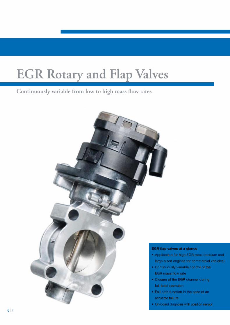
EGR Rotary and Flap ValvesContinuously variable from low to high mass flow rates
EGR flap valves at a glance
• ApplicationforhighEGRrates(mediumand
large-sizedenginesforcommercialvehicles)
• Continuouslyvariablecontrolofthe
EGRmassflowrate
•ClosureoftheEGRchannelduring
full-loadoperation
• Fail-safefunctioninthecaseofan
actuatorfailure
•On-boarddiagnosiswithpositionsensor
EGR Rotary and Flap Valves
With the increasing complexity of modern
combustion engines, the demands made
on EGR components change. Due to the
differing laws on emissions, different
requirements result world-wide. New
valves have been developed as a result
of increasing exhaust counter pressure
and variable differential pressure on the
valve, the demand for continuously
variable control of large flow rates and an
exact control of small quantities of
exhaust gas.
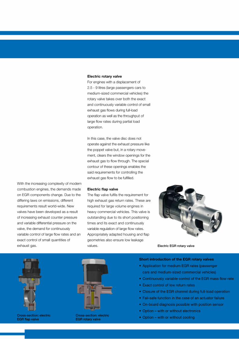
Electric rotary valve
For engines with a displacement of
2.5 - 9 litres (large passengers cars to
medium-sized commercial vehicles) the
rotary valve takes over both the exact
and continuously variable control of small
exhaust gas flows during full-load
oper ation as well as the throughput of
large flow rates during partial load
operation.
In this case, the valve disc does not
operate against the exhaust pressure like
the poppet valve but, in a rotary move-
ment, clears the window openings for the
exhaust gas to flow through. The special
contour of these openings enables the
said requirements for controlling the
exhaust gas flow to be fulfilled.
Electric flap valve
The flap valve fulfils the requirement for
high exhaust gas return rates. These are
required for large volume engines in
heavy commercial vehicles. This valve is
outstanding due to its short positioning
times and its exact and continuously
variable regulation of large flow rates.
Appropriately adapted housing and flap
geometries also ensure low leakage
values.
Cross-section: electric EGR flap valve
Cross-section: electric EGR rotary valve
Short introduction of the EGR rotary valves
• ApplicationformediumEGRrates(passenger
carsandmedium-sizedcommercialvehicles)
• ContinuouslyvariablecontroloftheEGRmassflowrate
• Exactcontroloflowreturnrates
•ClosureoftheEGRchannelduringfull-loadoperation
• Fail-safefunctioninthecaseofanactuatorfailure
•On-boarddiagnosispossiblewithpositionsensor
•Option–withorwithoutelectronics
•Option–withorwithoutcooling
Electric EGR rotary valve
8 9
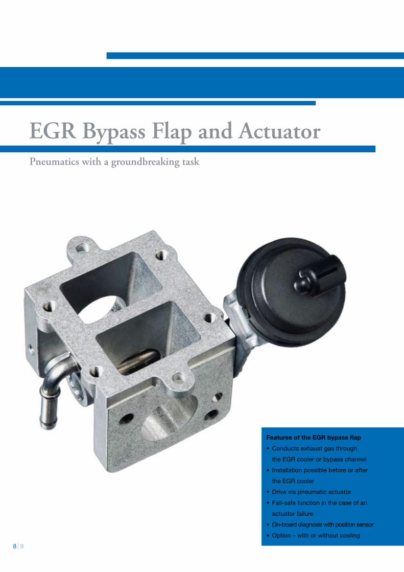
EGR Bypass Flap and ActuatorPneumatics with a groundbreaking task
Features of the EGR bypass flap
•Conductsexhaustgasthrough
theEGRcoolerorbypasschannel
• Installationpossiblebeforeorafter
theEGRcooler
• Driveviapneumaticactuator
• Fail-safefunctioninthecaseofan
actuatorfailure
• On-boarddiagnosiswithpositionsensor
•Option–withorwithoutcooling
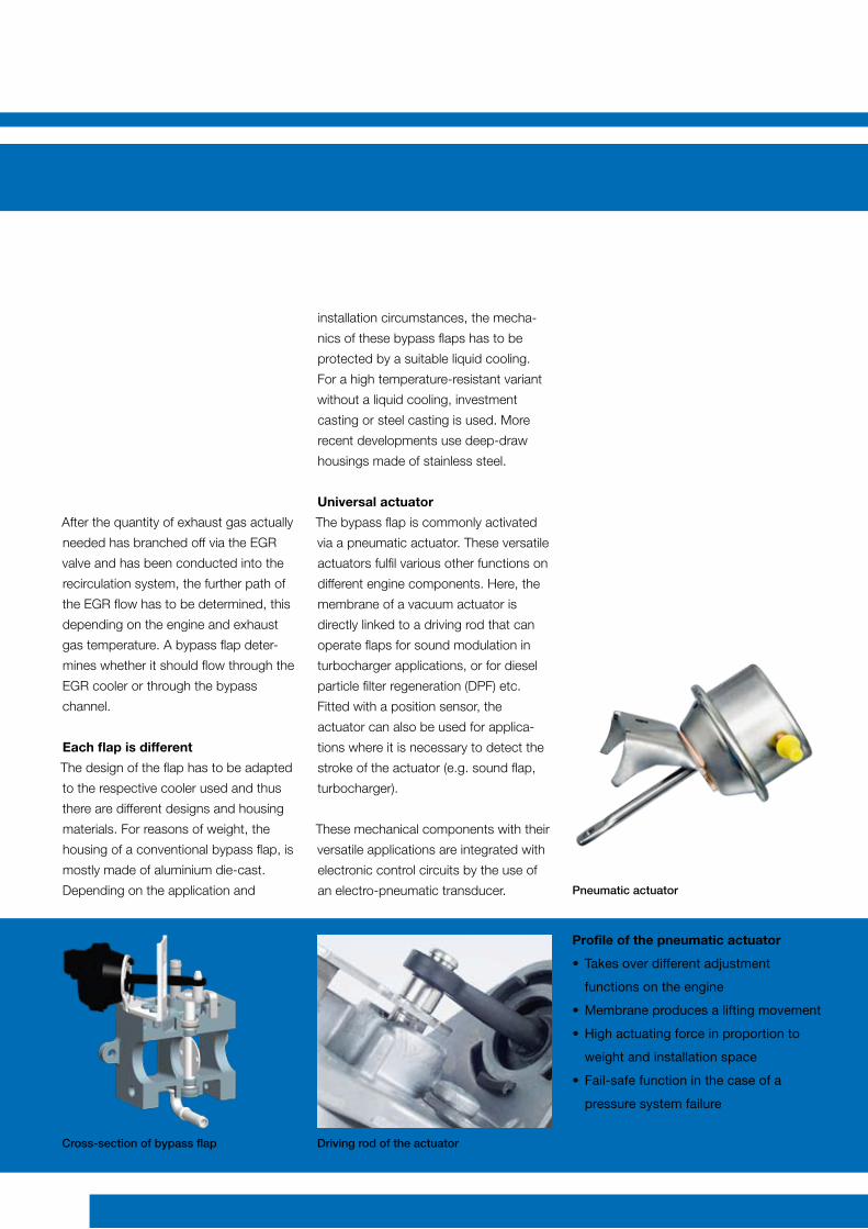
Pneumatic actuator
After the quantity of exhaust gas actually
needed has branched off via the EGR
valve and has been conducted into the
recirculation system, the further path of
the EGR flow has to be determined, this
depending on the engine and exhaust
gas temperature. A bypass flap deter-
mines whether it should flow through the
EGR cooler or through the bypass
channel.
Each flap is different
The design of the flap has to be adapted
to the respective cooler used and thus
there are different designs and housing
materials. For reasons of weight, the
housing of a conventional bypass flap, is
mostly made of aluminium die-cast.
Depending on the application and
installation circumstances, the mecha-
nics of these bypass flaps has to be
protected by a suitable liquid cooling.
For a high temperature-resistant variant
without a liquid cooling, investment
casting or steel casting is used. More
recent developments use deep-draw
housings made of stainless steel.
Universal actuator
The bypass flap is commonly activated
via a pneumatic actuator. These versatile
actuators fulfil various other functions on
different engine components. Here, the
membrane of a vacuum actuator is
directly linked to a driving rod that can
operate flaps for sound modulation in
turbocharger applications, or for diesel
particle filter regeneration (DPF) etc.
Fitted with a position sensor, the
actuator can also be used for applica-
tions where it is necessary to detect the
stroke of the actuator (e.g. sound flap,
turbocharger).
These mechanical components with their
versatile applications are integrated with
electronic control circuits by the use of
an electro-pneumatic transducer.
Driving rod of the actuatorCross-section of bypass flap
Profile of the pneumatic actuator
• Takesoverdifferentadjustment
functionsontheengine
•Membraneproducesaliftingmovement
•Highactuatingforceinproportionto
weightandinstallationspace
• Fail-safefunctioninthecaseofa
pressuresystemfailure
10 11
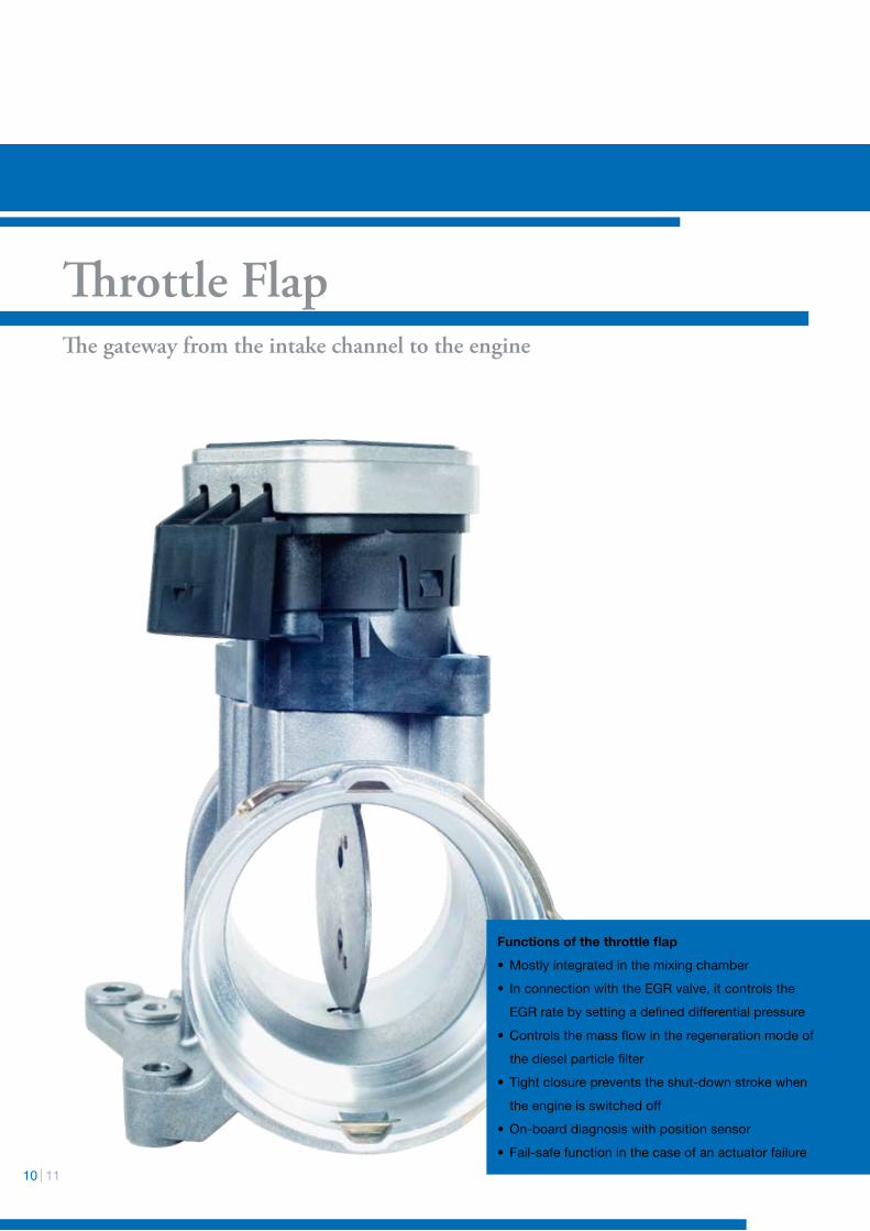
Throttle FlapThe gateway from the intake channel to the engine
Functions of the throttle flap
•Mostlyintegratedinthemixingchamber
• InconnectionwiththeEGRvalve,itcontrolsthe
EGRratebysettingadefineddifferentialpressure
•Controlsthemassflowintheregenerationmodeof
thedieselparticlefilter
• Tightclosurepreventstheshut-downstrokewhen
theengineisswitchedoff
•On-boarddiagnosiswithpositionsensor
• Fail-safefunctioninthecaseofanactuatorfailure
0°
Klappe B bei 10 hPa
Klappe A bei 10 hPa
Endwinkel 75°
Endwinkel 70°
Fris
chlu
ftdur
chsa
tz [k
g/h]
Öffnungswinkel [ °]
10° 20°0
100
200
300
400
500
40°30° 50° 60° 70° 80°
As a rule, the throttle flap is mostly inte-
grated in the mixing chamber. Originally
its scope of application was restricted to
throttling the intake air in diesel engines
and – by increasing the differential pres-
sure – thereby increasing the amount of
the returned exhaust gas. The demands
for control precision and manipulating
speed were comparably low.
Fitting accuracy
Today’s diesel engines however, have to
be operated with a defined air/fuel
mixture, similar to gasoline engines. The
modern throttle flaps take over important
functions, e.g. the control of the inco-
ming amount of air in the mode of the
diesel particle filter regeneration. Com-
plete closure of the throttle flap enables
the temperature in the particle filter to
increase until burn-off. The tight closure
of the throttle flap is also beneficial when
turning off the diesel engine. By inter-
rupting the air-mass flow the engine only
sucks in air at a very low density and
stops without juddering. This contributes
towards improving comfort, especially
where large-volume engines in commer-
cial vehicles are concerned.
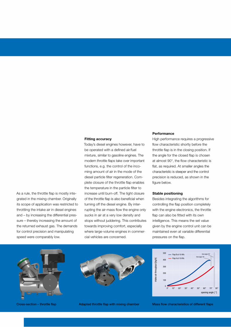
Performance
High performance requires a progressive
flow characteristic shortly before the
throttle flap is in the closing position. If
the angle for the closed flap is chosen
at almost 90°, the flow characteristic is
flat, as required. At smaller angles the
characteristic is steeper and the control
precision is reduced, as shown in the
figure below.
Stable positioning
Besides integrating the algorithms for
controlling the flap position completely
with the engine electronics, the throttle
flap can also be fitted with its own
intelligence. This means the set value
given by the engine control unit can be
maintained even at variable differential
pressures on the flap.
Cross-section – throttle flap Adapted throttle flap with mixing chamber Mass flow characteristics of different flaps
0°
Flap B at 10 hPa
Flap A at 10 hPa
End angle 75°
End angle 70°
inta
ke a
ir th
roug
hput
[kg/
h]
opening angle [ °]
10° 20°0
100
200
300
400
500
40°30° 50° 60° 70° 80°
12 13
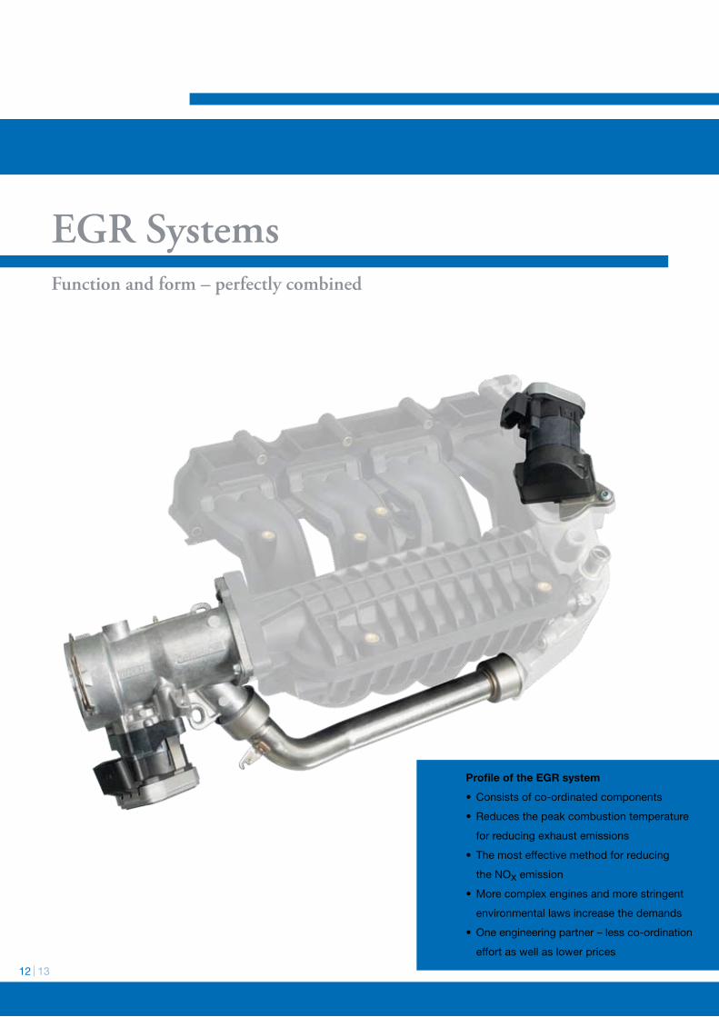
Function and form – perfectly combined
Profile of the EGR system
•Consistsofco-ordinatedcomponents
• Reducesthepeakcombustiontemperature
forreducingexhaustemissions
• Themosteffectivemethodforreducing
theNOxemission
•Morecomplexenginesandmorestringent
environmentallawsincreasethedemands
•Oneengineeringpartner–lessco-ordination
effortaswellaslowerprices
EGR Systems
The engine concepts and thus also the
concepts for exhaust gas return are
undergoing continual further develop-
ment. The individual components have
to be adapted mutually in an optimum
way, in order to fulfil the high demands
for control precision and speed.
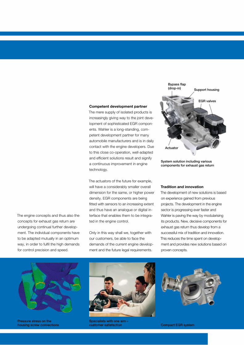
Competent development partner
The mere supply of isolated products is
increasingly giving way to the joint deve-
lopment of sophisticated EGR compon-
ents. Wahler is a long-standing, com-
petent development partner for many
automobile manufacturers and is in daily
contact with the engine developers. Due
to this close co-operation, well-adapted
and efficient solutions result and signify
a continuous improvement in engine
technology.
The actuators of the future for example,
will have a considerably smaller overall
dimension for the same, or higher power
density. EGR components are being
fitted with sensors to an increasing extent
and thus have an analogue or digital in-
terface that enables them to be integra-
ted in the engine control.
Only in this way shall we, together with
our customers, be able to face the
demands of the current engine develop-
ment and the future legal requirements.
Tradition and innovation
The development of new solutions is based
on experience gained from previous
projects. The development in the engine
sector is progressing ever faster and
Wahler is paving the way by modularising
its products. New, decisive components for
exhaust gas return thus develop from a
successful mix of tradition and innovation.
This reduces the time spent on develop-
ment and provides new solutions based on
proven concepts.
Compact EGR system
System solution including various components for exhaust gas return
Pressure stress on the housing screw connections
Specialists with one aim – customer satisfaction
Bypass flap (drop-in) Support housing
Actuator
EGR valves
14 15
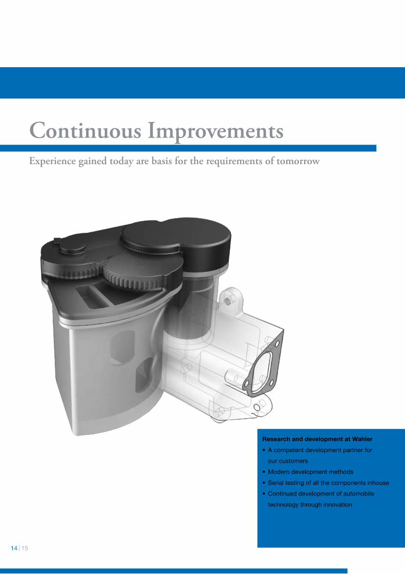
Continuous ImprovementsExperience gained today are basis for the requirements of tomorrow
Research and development at Wahler
• Acompetentdevelopmentpartnerfor
ourcustomers
•Moderndevelopmentmethods
• Serialtestingofallthecomponentsinhouse
•Continueddevelopmentofautomobile
technologythroughinnovation
At Wahler the product engineering
process is determined by the quality
assurance specifications of the automo-
tive industry (VDA standards, QS 9000,
DIN ISO 16949) and based on the
progressive methods of APQP (Advan-
ced Process Quality Planning).
Different aspects
A process-oriented structural organisati-
on accompanies the development
process from the initial idea through to
the readiness for series production.
Specialists from the Development,
Production, Quality Assurance, Purcha-
sing, Sales and Logistics already
contribute their experience at an early
phase in the new product’s develop-
ment.
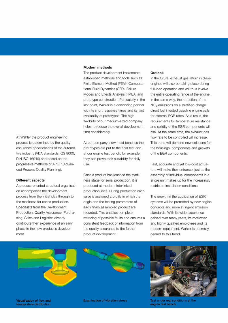
Modern methods
The product development implements
established methods and tools such as
Finite Element Method (FEM), Computa-
tional Fluid Dynamics (CFD), Failure
Modes and Effects Analysis (FMEA) and
prototype construction. Particularly in the
last point, Wahler is a convincing partner
with its short response times and its fast
availability of prototypes. The high
flexibility of our medium-sized company
helps to reduce the overall development
time considerably.
At our company's own test benches the
prototypes are put to the acid test and
at our engine test bench, for example,
they can prove their suitability for daily
use.
Once a product has reached the readi-
ness stage for serial production, it is
produced at modern, interlinked
production lines. During production each
valve is assigned a profile in which the
origin and the testing parameters of
each finally assembled product are
recorded. This enables complete
retracing of possible faults and ensures a
consistent feedback of information from
the quality assurance to the further
product development.
Outlook
In the future, exhaust gas return in diesel
engines will also be taking place during
full-load operation and will thus involve
the entire operating range of the engine.
In the same way, the reduction of the
NOx emissions on a stratified-charge
direct fuel injected gasoline engine calls
for external EGR rates. As a result, the
requirements for temperature resistance
and solidity of the EGR components will
rise. At the same time, the exhaust gas
flow rate to be controlled will increase.
This trend will demand new solutions for
the housings, components and gaskets
of the EGR components.
Fast, accurate and yet low-cost actua-
tors will make their entrance, just as the
assembly of individual components in a
single unit makes up for the increasingly
restricted installation conditions.
The growth in the application of EGR
systems will be promoted by new engine
concepts and more stringent emission
standards. With its wide experience
gained over many years, its motivated
and highly qualified employees and its
modern equipment, Wahler is optimally
geared to this trend.
Visualisation of flow and temperature distribution
Examination of vibration stress Test under real conditions at the engine test bench
Gustav Wahler GmbH u. Co. KG
Hindenburgstrasse 146 73730 Esslingen Germany
Phone: +49 711 3152-0 Fax: +49 711 3152-210 Email: [email protected] Internet: www.wahler.de