Embed Size (px)
Citation preview

IMPORTANT: Fill in pertinent information on page 2 for future reference.
MODEL 3900Service Manual
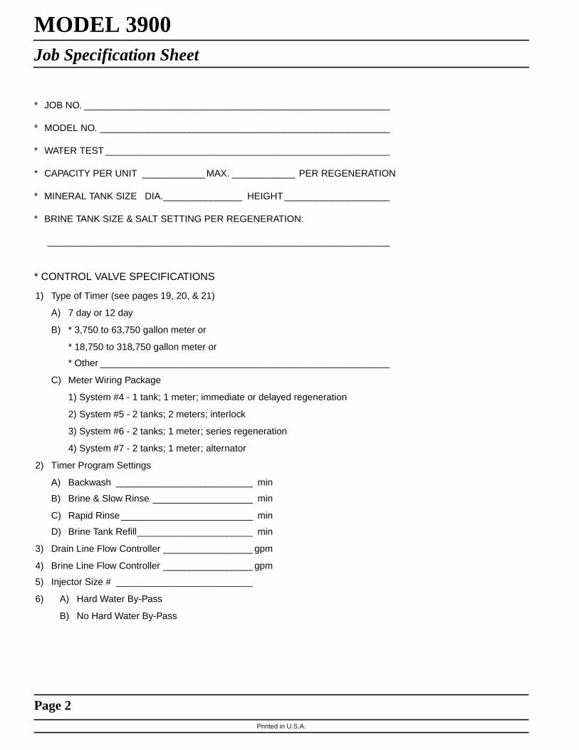
MODEL 3900Job Specification Sheet
Printed in U.S.A.
* JOB NO. __________________________________________________________
* MODEL NO. _______________________________________________________
* WATER TEST ______________________________________________________
* CAPACITY PER UNIT ____________MAX. ____________ PER REGENERATION
* MINERAL TANK SIZE DIA._______________ HEIGHT ____________________
* BRINE TANK SIZE & SALT SETTING PER REGENERATION:
_________________________________________________________________
Page 2
* CONTROL VALVE SPECIFICATIONS
1) Type of Timer (see pages 19, 20, & 21)
A) 7 day or 12 day
B) * 3,750 to 63,750 gallon meter or
* 18,750 to 318,750 gallon meter or
* Other _______________________________________________________
C) Meter Wiring Package
1) System #4 - 1 tank; 1 meter; immediate or delayed regeneration
2) System #5 - 2 tanks; 2 meters; interlock
3) System #6 - 2 tanks; 1 meter; series regeneration
4) System #7 - 2 tanks; 1 meter; alternator
2) Timer Program Settings
A) Backwash __________________________ min
B) Brine & Slow Rinse ___________________ min
C) Rapid Rinse _________________________ min
D) Brine Tank Refill______________________ min
3) Drain Line Flow Controller _________________ gpm
4) Brine Line Flow Controller _________________ gpm
5) Injector Size # __________________________
6) A) Hard Water By-Pass
B) No Hard Water By-Pass

Printed in U.S.A.
Page 3
MODEL 3900General Commercial Pre-Installation Check List
WATER PRESSURE: A minimum of 25 pounds of water pressure is required for regeneration valve to operateeffectively.
ELECTRICAL FACILITIES: A continuous 115 volt, 60 Hertz current supply is required. (Other voltages available.)Make certain the current supply is always hot and cannot be turned off with another switch.
EXISTING PLUMBING: Condition of existing plumbing should be free from lime and iron buildup. Piping that is built upheavily with lime and/or iron should be replaced. If piping is clogged with iron, a separate iron filter unit should beinstalled ahead of the water softener.
LOCATION OF SOFTENER AND DRAIN: The softener should be located close to a drain.
BY-PASS VALVES: Always provide for the installation of a by-pass valve.
CAUTION: Water pressure is not to exceed 120 p.s.i., water temperature is not to exceed 110° F, and the unit cannotbe subjected to freezing conditions.
INSTALLATION INSTRUCTIONS
1. Place the softener tank where you want to install the unit making sure the unit is level and on a firm base.(Maximum 7 feet apart for twin units.) To provide for expansion and contraction of plastic resin tanks and rigidplumbing loads, use FLEXIBLE FITTINGS at the valve.
2. All plumbing should be done in accordance with local plumbing codes. The pipe size for the drain line should be thesame size as the drain line flow control connection. Water meters are to be installed on soft water outlets. Twinunits with (1) one meter shall be installed on common soft water outlet of units.
3. Make sure that the floor is clean beneath the salt storage tank and that it is level.
4. Place approximately 1″ of water above the grid plate (if used) in your salt tank. Salt may be placed in the unit at thistime.
5. Place in by-pass position. Turn on the main water supply. Open a cold soft water tap nearby and let run a fewminutes or until the system is free from foreign material (usually solder) that may have resulted from theinstallation.
6. Place the by-pass in service position.
7. Manually index the softener control into “service” position and let water flow into the mineral tank. When water flowstops, close inlet valve, place control in “backwash” position to relieve head of air, then gradually open inlet valve topurge remaining air in tank. Return control to “service” position.
8. Electrical: All electrical connections must be connected according to codes. Use electrical conduit if applicable.Plug into power supply.

Printed in U.S.A.
Page 4
MODEL 3900Water Conditioner Flow Diagrams
1 SERVICE POSITION
2 BACKWASH POSITION 3 BRINE POSITION
Hard water enters at valve inlet and flows down thru mineral to the bottom distributor. Conditioned waterflows up thru the distributor tube, around the piston and out the outlet.
Hard water enters at valve inlet flows thru service adapterpiston for by-pass, and up thru coupling to regeneration valveinlet. Flow continues thru the regeneration valve piston downthe distributor tube thru the bottom distributor and up thru themineral around the piston and out the drain. If optional nohard water by-pass piston is used, water flow to service outlet isprevented by an extension on the service outlet until the end ofthe rapid rinse cycle or brine tank refill cycle, depending onoptions chosen.
Hard water enters at valve inlet flows thru injector nozzle and throatto draw brine from the brine tank. Brine flows down thru the mineral into the bottom distributor up the distributor tube around thepiston and out the drain.
DRAIN
INLET
REGENERATIONVALVE
SERVICEVALVE
SERVICEOUTLET
INLET
DRAIN
INLET
DRAIN
INLET
NO HARD WATER BY-PASS
SERVICE OUTLET

Printed in U.S.A.
Page 5
MODEL 3900Water Conditioner Flow Diagrams (Cont’d.)
4 SLOW RINSE POSITION
5 RAPID RINSE POSITION 6 BRINE TANK REFILL POSITION
Hard water enters at valve inlet flows thru injector nozzle and throat down thru the mineral into thebottom distributor up the distributor tube around the piston and out the drain..
Hard water enters at valve inlet flows thru the regenerationvalve directly down thru the mineral into the bottom distributor up the distributor tube around the piston and out the drain.
Hard water enters at valve inlet flows thru nozzle and thru throat tobrine valve to refill the brine tank. Inlet flow also continues down thrumineral to the bottom distributor. Conditioned water flows up thru thedistributor tube, around the piston and out the outlet. Note: An optionis available to keep service valve in by-pass position until the end ofbrine tank refill cycle.
DRAIN
INLET
DRAIN
INLET
SERVICEOUTLET
INLET
DRAIN
INLET
Printed in U.S.A.
Page 6
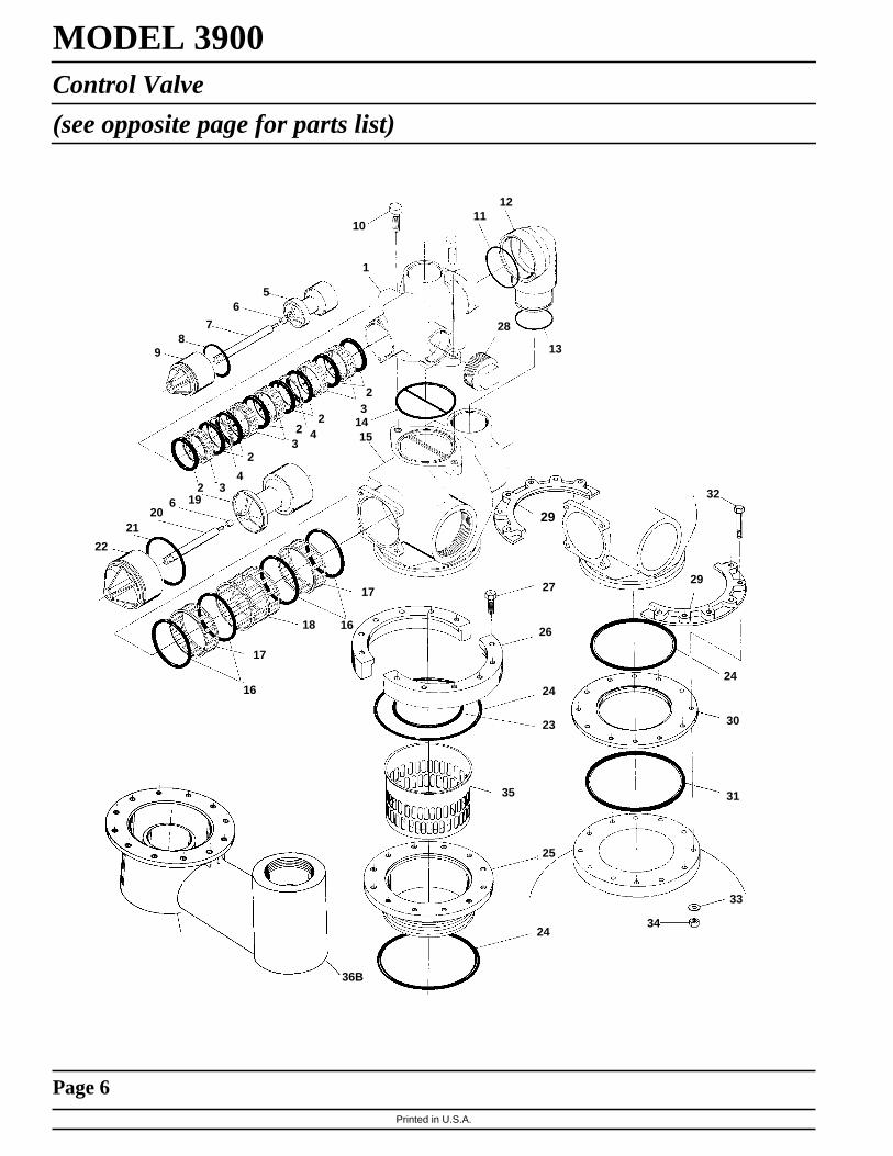
MODEL 3900Control Valve
(see opposite page for parts list)
10
1
1211
56
78
9
2 34
232 4
23
2
22
2120
6 19
17
1618
17
16
15
13
28
32
29
24
30
31
33
34
27
26
24
23
35
25
24
36B
14
29

Printed in U.S.A.
Page 7
MODEL 3900Control Valve
Parts List
Item No. Quantity Part No. Description1. . . . . . . . . . . 1 . . . . . . . . . . . 15114 . . . . . . . . . . . . . . . Valve Body2. . . . . . . . . . . 8 . . . . . . . . . . . 11720 . . . . . . . . . . . . . . . Seal
8 . . . . . . . . . . . 11720-02 . . . . . . . . . . . . . Seal, Silicone3. . . . . . . . . . . 5 . . . . . . . . . . . 10369 . . . . . . . . . . . . . . . Spacer - Port4. . . . . . . . . . . 2 . . . . . . . . . . . 10368 . . . . . . . . . . . . . . . Spacer
10368-01 . . . . . . . . . . . . . Spacer, Hot Water5. . . . . . . . . . . 1 . . . . . . . . . . . 16130 . . . . . . . . . . . . . . . Piston6. . . . . . . . . . . 2 . . . . . . . . . . . 14818 . . . . . . . . . . . . . . . Clip - Piston Rod7. . . . . . . . . . . 1 . . . . . . . . . . . 15125 . . . . . . . . . . . . . . . Piston Rod8. . . . . . . . . . . 1 . . . . . . . . . . . 14922 . . . . . . . . . . . . . . . O-Ring -0359. . . . . . . . . . . 1 . . . . . . . . . . . 16398-01 . . . . . . . . . . . . . End Plug Assembly
10 . . . . . . . . . . 2 . . . . . . . . . . . 40118 . . . . . . . . . . . . . . . Screw - Hex Hd.11 . . . . . . . . . . 1 . . . . . . . . . . . 16078 . . . . . . . . . . . . . . . O-Ring - 14912 . . . . . . . . . . 1 . . . . . . . . . . . 16074 . . . . . . . . . . . . . . . Coupling13 . . . . . . . . . . 1 . . . . . . . . . . . 16077 . . . . . . . . . . . . . . . O-Ring - 14014 . . . . . . . . . . 1 . . . . . . . . . . . 15112 . . . . . . . . . . . . . . . Seal15 . . . . . . . . . . 1 . . . . . . . . . . . 16067-02 . . . . . . . . . . . . . 3″ Adapter Body16 . . . . . . . . . . 4 . . . . . . . . . . . 16068 . . . . . . . . . . . . . . . Seal
4 . . . . . . . . . . . 16068-02 . . . . . . . . . . . . . Seal, Silicone17 . . . . . . . . . . 2 . . . . . . . . . . . 16069 . . . . . . . . . . . . . . . Spacer - Narrow
2 . . . . . . . . . . . 16069-01 . . . . . . . . . . . . . Spacer - Narrow, Hot Water18 . . . . . . . . . . 1 . . . . . . . . . . . 16070 . . . . . . . . . . . . . . . Spacer - Wide
1 . . . . . . . . . . . 16070-01 . . . . . . . . . . . . . Spacer - Wide, Hot Water19 . . . . . . . . . . 1 . . . . . . . . . . . 16071 . . . . . . . . . . . . . . . Piston
1 . . . . . . . . . . . 16082 . . . . . . . . . . . . . . . Piston - No Hard Water By-Pass20 . . . . . . . . . . 1 . . . . . . . . . . . 16072 . . . . . . . . . . . . . . . Piston Rod21 . . . . . . . . . . 1 . . . . . . . . . . . 16076 . . . . . . . . . . . . . . . O-Ring - 04222 . . . . . . . . . . 1 . . . . . . . . . . . 16399-01 . . . . . . . . . . . . . End Plug Assy - White
1 . . . . . . . . . . . 16399-11 . . . . . . . . . . . . . End Plug Assy - Black, NHWB-P1 . . . . . . . . . . . 19901 . . . . . . . . . . . . . . . End Plug Assy - Brass, Hot Water
23 . . . . . . . . . . 1 . . . . . . . . . . . 16800 . . . . . . . . . . . . . . . O-Ring - 23824 . . . . . . . . . . 2 . . . . . . . . . . . 16345 . . . . . . . . . . . . . . . O-Ring - 36225 . . . . . . . . . . 1 . . . . . . . . . . . 16255 . . . . . . . . . . . . . . . Tank Adapter - 6″ -8
1 . . . . . . . . . . . 16256 . . . . . . . . . . . . . . . Welded Flange26 . . . . . . . . . . 2 . . . . . . . . . . . 16257 . . . . . . . . . . . . . . . Flange Segment27 . . . . . . . . . . 12 . . . . . . . . . . 11238 . . . . . . . . . . . . . . . Screw - Hex Hd.28 . . . . . . . . . . 1 . . . . . . . . . . . 16088 . . . . . . . . . . . . . . . Pipe Plug - 2″ NPT35 . . . . . . . . . . 1 . . . . . . . . . . . 16258 . . . . . . . . . . . . . . . Flow Disperser
Options
29 . . . . . . . . . . 2 . . . . . . . . . . . 16482 . . . . . . . . . . . . . . . Flange Segment30 . . . . . . . . . . 1 . . . . . . . . . . . 16483 . . . . . . . . . . . . . . . Flange Ring31 . . . . . . . . . . 1 . . . . . . . . . . . 16484 . . . . . . . . . . . . . . . O-Ring -44232 . . . . . . . . . . 12 . . . . . . . . . . 16517 . . . . . . . . . . . . . . . Screw, Park Tank
12 . . . . . . . . . . 19592 . . . . . . . . . . . . . . . Screw, Structural Tank33 . . . . . . . . . . 12 . . . . . . . . . . 18619 . . . . . . . . . . . . . . . Washer34 . . . . . . . . . . 12 . . . . . . . . . . 16346 . . . . . . . . . . . . . . . Nut35 . . . . . . . . . . 1 . . . . . . . . . . . 19608-20 . . . . . . . . . . . . . Disperser (Upper)36B . . . . . . . . . 1 . . . . . . . . . . . 18584 . . . . . . . . . . . . . . . Adapter, Side Mount

Printed in U.S.A.
Page 8
MODEL 3900Control Drive Assembly
(see opposite page for parts list)
28B26
2524
2322
2120
19
1817
1615
14
13
1110
98
7 6 54 3
2 1
43
42
164140
3938
3736
3534
33
32
31
3029
28A
27

Printed in U.S.A.
Page 9
MODEL 3900Control Drive Assembly
Parts ListItem No. Quantity Part No. Description
1. . . . . . . . . . . . 1 . . . . . . . . . . . . . 19304-00 . . . . . . . . . . . .Back Plate -01, -022. . . . . . . . . . . . 1 . . . . . . . . . . . . . 15120-01 . . . . . . . . . . . .Bracket - Motor Mounting3. . . . . . . . . . . . 2 . . . . . . . . . . . . . 16346 . . . . . . . . . . . . . . .Nut - 5/16 - 184. . . . . . . . . . . . 1 . . . . . . . . . . . . . 16044 . . . . . . . . . . . . . . .Drive Motor - 115 V. 60 Hz.
16500 . . . . . . . . . . . . . . .Drive Motor - 220 V. 50 Hz.16501 . . . . . . . . . . . . . . .Drive Motor - 24 V. 60 Hz.
5 . . . . . . . . . . . . 1 . . . . . . . . . . . . . 17797 . . . . . . . . . . . . . . .Bracket - Switch Mounting6. . . . . . . . . . . . 4 . . . . . . . . . . . . . 10302 . . . . . . . . . . . . . . .Insulator - Switch7. . . . . . . . . . . . 3 . . . . . . . . . . . . . 10218 . . . . . . . . . . . . . . .Switch8. . . . . . . . . . . . 1 . . . . . . . . . . . . . 17845-03 . . . . . . . . . . . .Pin, Hinge9. . . . . . . . . . . . 4 . . . . . . . . . . . . . 11235 . . . . . . . . . . . . . . .Nut, 1/4 - 20
10. . . . . . . . . . . . 2 . . . . . . . . . . . . . 13365 . . . . . . . . . . . . . . .Lockwasher11. . . . . . . . . . . . 2 . . . . . . . . . . . . . 12624 . . . . . . . . . . . . . . .Screw - Pan Hd.13. . . . . . . . . . . . 1 . . . . . . . . . . . . . 16053 . . . . . . . . . . . . . . .Bracket - Brine Side14. . . . . . . . . . . . 2 . . . . . . . . . . . . . 40133 . . . . . . . . . . . . . . .Screw - Round Hd.15. . . . . . . . . . . . 1 . . . . . . . . . . . . . 15226-✽ . . . . . . . . . . . . .Terminal Block16. . . . . . . . . . . . 2 . . . . . . . . . . . . . 16052 . . . . . . . . . . . . . . .Bushing17. . . . . . . . . . . . 1 . . . . . . . . . . . . . 16059 . . . . . . . . . . . . . . .Washer18. . . . . . . . . . . . 1 . . . . . . . . . . . . . 16051 . . . . . . . . . . . . . . .Retaining Ring - Bowed “E”
•19 . . . . . . . . . . . 2 . . . . . . . . . . . . . 10300 . . . . . . . . . . . . . . .Screw - Hex - Hex Hd Thread Cutting•20 . . . . . . . . . . . 1 . . . . . . . . . . . . . 19317 . . . . . . . . . . . . . . .Light Bracket21. . . . . . . . . . . . 4 . . . . . . . . . . . . . 10231 . . . . . . . . . . . . . . .Screw - Hex Hd.22. . . . . . . . . . . . 2 . . . . . . . . . . . . . 17567 . . . . . . . . . . . . . . .Screw - Hex Hd.23. . . . . . . . . . . . 2 . . . . . . . . . . . . . 12288 . . . . . . . . . . . . . . .Washer, Lock, #8 Internal24. . . . . . . . . . . . 1 . . . . . . . . . . . . . 16494-05 . . . . . . . . . . . .Cam Assembly - Service After RR
1 . . . . . . . . . . . . . 16494-03 . . . . . . . . . . . .Cam Assembly - Service After Brine Refill25. . . . . . . . . . . . 4 . . . . . . . . . . . . . 11224 . . . . . . . . . . . . . . .Screw - Hex Hd.
•26 . . . . . . . . . . . 1 . . . . . . . . . . . . . 19319 . . . . . . . . . . . . . . .Lamp Window27. . . . . . . . . . . . 1 . . . . . . . . . . . . . 18744 . . . . . . . . . . . . . . .Screw28A . . . . . . . . . . 1 . . . . . . . . . . . . . 19277-020 . . . . . . . . . . .Cover, Black
•28B . . . . . . . . . . 1 . . . . . . . . . . . . . 19277-021 . . . . . . . . . . .Cover, Lamp Window29. . . . . . . . . . . . 1 . . . . . . . . . . . . . 18615-02 . . . . . . . . . . . .Seal, Window30. . . . . . . . . . . . 1 . . . . . . . . . . . . . 18745 . . . . . . . . . . . . . . .Window31. . . . . . . . . . . . 1 . . . . . . . . . . . . . 18716-03 . . . . . . . . . . . .Seal, Cover32. . . . . . . . . . . . 4 . . . . . . . . . . . . . 19203 . . . . . . . . . . . . . . .Screw33. . . . . . . . . . . . 1 . . . . . . . . . . . . . 16046 . . . . . . . . . . . . . . .Drive Gear34. . . . . . . . . . . . 1 . . . . . . . . . . . . . 16050 . . . . . . . . . . . . . . .Retaining Ring35. . . . . . . . . . . . 1 . . . . . . . . . . . . . 11774 . . . . . . . . . . . . . . .Retaining Ring “E”36. . . . . . . . . . . . 1 . . . . . . . . . . . . . 16047 . . . . . . . . . . . . . . .Drive Link37. . . . . . . . . . . . 1 . . . . . . . . . . . . . 11709 . . . . . . . . . . . . . . .Pin - Drive Link38. . . . . . . . . . . . 1 . . . . . . . . . . . . . 16048 . . . . . . . . . . . . . . .Bearing - Drive Link39. . . . . . . . . . . . 1 . . . . . . . . . . . . . 11898 . . . . . . . . . . . . . . .Clip40. . . . . . . . . . . . 1 . . . . . . . . . . . . . 16045 . . . . . . . . . . . . . . .Drive Pinion41. . . . . . . . . . . . 1 . . . . . . . . . . . . . 11381 . . . . . . . . . . . . . . .Roll Pin42. . . . . . . . . . . . 1 . . . . . . . . . . . . . 11080 . . . . . . . . . . . . . . .Screw - Flat Hd.43. . . . . . . . . . . . 3 . . . . . . . . . . . . . 10872 . . . . . . . . . . . . . . .Screw - Hex Hd.44. . . . . . . . . . . . 1 . . . . . . . . . . . . . . . . . . . . . . . . . . . . . . . . .Timer - (not shown) [3000, 3200, 3210, 3200E, 3200ET]45. . . . . . . . . . . . 1 . . . . . . . . . . . . . 40084-07 . . . . . . . . . . . .Power Cord, 120V, 7 Ft. (not shown)
1 . . . . . . . . . . . . . 40084-12 . . . . . . . . . . . .Power Cord, 120V, 12 Ft. (not shown)1 . . . . . . . . . . . . . 40085-07 . . . . . . . . . . . .Power Cord, 240V, 7 Ft. (not shown)
46. . . . . . . . . . . . 1 . . . . . . . . . . . . . 17967 . . . . . . . . . . . . . . .Strain Relief (not shown)47. . . . . . . . . . . . 1 . . . . . . . . . . . . . 16430 . . . . . . . . . . . . . . .Harness (not shown)48. . . . . . . . . . . . 1 . . . . . . . . . . . . . 19691 . . . . . . . . . . . . . . .Hole Plug - 3/4 Dia. (not shown)49. . . . . . . . . . . . 1 . . . . . . . . . . . . . 19591 . . . . . . . . . . . . . . .Hole Plug - 7/8 Dia. (not shown)50. . . . . . . . . . . . 1 . . . . . . . . . . . . . 16427-04 . . . . . . . . . . . .Motor Lead Wire (not shown)51. . . . . . . . . . . . 1 . . . . . . . . . . . . . 16384 . . . . . . . . . . . . . . .Wire Harness (not shown)52. . . . . . . . . . . . 1 . . . . . . . . . . . . . 14924 . . . . . . . . . . . . . . .Strain Relief (not shown)53. . . . . . . . . . . . 1 . . . . . . . . . . . . . 15513 . . . . . . . . . . . . . . .Meter Cable (not shown)54. . . . . . . . . . . . 2 . . . . . . . . . . . . . 15250 . . . . . . . . . . . . . . .Label - Terminal Strip (not shown)55. . . . . . . . . . . . 1 . . . . . . . . . . . . . 16821 . . . . . . . . . . . . . . .Cable Guide Assembly (not shown)
✽ Specify number of terminals• Optional Parts for Lamp Package

Printed in U.S.A.
Page 10
MODEL 3900Adapter Control Drive
(see opposite page for parts list)
1
1534
4241
4039
3837
3635
3433
3231
3029
28
27
26
25
24
2345678
910
6
11
13
14
1516
17
18
19
2021
22
23
12
Printed in U.S.A.
Page 11
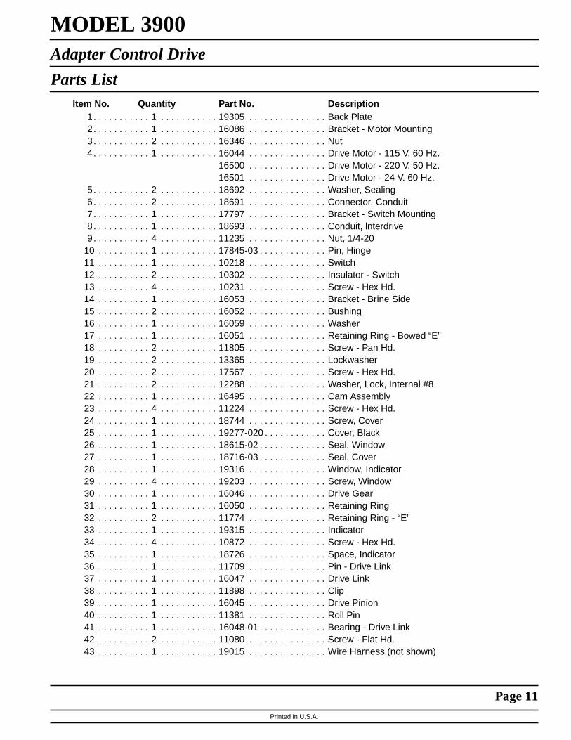
MODEL 3900Adapter Control Drive
Parts ListItem No. Quantity Part No. Description
1. . . . . . . . . . . 1 . . . . . . . . . . . 19305 . . . . . . . . . . . . . . . Back Plate2. . . . . . . . . . . 1 . . . . . . . . . . . 16086 . . . . . . . . . . . . . . . Bracket - Motor Mounting3. . . . . . . . . . . 2 . . . . . . . . . . . 16346 . . . . . . . . . . . . . . . Nut4. . . . . . . . . . . 1 . . . . . . . . . . . 16044 . . . . . . . . . . . . . . . Drive Motor - 115 V. 60 Hz.
16500 . . . . . . . . . . . . . . . Drive Motor - 220 V. 50 Hz.16501 . . . . . . . . . . . . . . . Drive Motor - 24 V. 60 Hz.
5. . . . . . . . . . . 2 . . . . . . . . . . . 18692 . . . . . . . . . . . . . . . Washer, Sealing6. . . . . . . . . . . 2 . . . . . . . . . . . 18691 . . . . . . . . . . . . . . . Connector, Conduit7. . . . . . . . . . . 1 . . . . . . . . . . . 17797 . . . . . . . . . . . . . . . Bracket - Switch Mounting8. . . . . . . . . . . 1 . . . . . . . . . . . 18693 . . . . . . . . . . . . . . . Conduit, lnterdrive9. . . . . . . . . . . 4 . . . . . . . . . . . 11235 . . . . . . . . . . . . . . . Nut, 1/4-20
10 . . . . . . . . . . 1 . . . . . . . . . . . 17845-03 . . . . . . . . . . . . . Pin, Hinge11 . . . . . . . . . . 1 . . . . . . . . . . . 10218 . . . . . . . . . . . . . . . Switch12 . . . . . . . . . . 2 . . . . . . . . . . . 10302 . . . . . . . . . . . . . . . Insulator - Switch13 . . . . . . . . . . 4 . . . . . . . . . . . 10231 . . . . . . . . . . . . . . . Screw - Hex Hd.14 . . . . . . . . . . 1 . . . . . . . . . . . 16053 . . . . . . . . . . . . . . . Bracket - Brine Side15 . . . . . . . . . . 2 . . . . . . . . . . . 16052 . . . . . . . . . . . . . . . Bushing16 . . . . . . . . . . 1 . . . . . . . . . . . 16059 . . . . . . . . . . . . . . . Washer17 . . . . . . . . . . 1 . . . . . . . . . . . 16051 . . . . . . . . . . . . . . . Retaining Ring - Bowed “E”18 . . . . . . . . . . 2 . . . . . . . . . . . 11805 . . . . . . . . . . . . . . . Screw - Pan Hd.19 . . . . . . . . . . 2 . . . . . . . . . . . 13365 . . . . . . . . . . . . . . . Lockwasher20 . . . . . . . . . . 2 . . . . . . . . . . . 17567 . . . . . . . . . . . . . . . Screw - Hex Hd.21 . . . . . . . . . . 2 . . . . . . . . . . . 12288 . . . . . . . . . . . . . . . Washer, Lock, Internal #822 . . . . . . . . . . 1 . . . . . . . . . . . 16495 . . . . . . . . . . . . . . . Cam Assembly23 . . . . . . . . . . 4 . . . . . . . . . . . 11224 . . . . . . . . . . . . . . . Screw - Hex Hd.24 . . . . . . . . . . 1 . . . . . . . . . . . 18744 . . . . . . . . . . . . . . . Screw, Cover25 . . . . . . . . . . 1 . . . . . . . . . . . 19277-020 . . . . . . . . . . . . Cover, Black26 . . . . . . . . . . 1 . . . . . . . . . . . 18615-02 . . . . . . . . . . . . . Seal, Window27 . . . . . . . . . . 1 . . . . . . . . . . . 18716-03 . . . . . . . . . . . . . Seal, Cover28 . . . . . . . . . . 1 . . . . . . . . . . . 19316 . . . . . . . . . . . . . . . Window, Indicator29 . . . . . . . . . . 4 . . . . . . . . . . . 19203 . . . . . . . . . . . . . . . Screw, Window30 . . . . . . . . . . 1 . . . . . . . . . . . 16046 . . . . . . . . . . . . . . . Drive Gear31 . . . . . . . . . . 1 . . . . . . . . . . . 16050 . . . . . . . . . . . . . . . Retaining Ring32 . . . . . . . . . . 2 . . . . . . . . . . . 11774 . . . . . . . . . . . . . . . Retaining Ring - “E”33 . . . . . . . . . . 1 . . . . . . . . . . . 19315 . . . . . . . . . . . . . . . Indicator34 . . . . . . . . . . 4 . . . . . . . . . . . 10872 . . . . . . . . . . . . . . . Screw - Hex Hd.35 . . . . . . . . . . 1 . . . . . . . . . . . 18726 . . . . . . . . . . . . . . . Space, Indicator36 . . . . . . . . . . 1 . . . . . . . . . . . 11709 . . . . . . . . . . . . . . . Pin - Drive Link37 . . . . . . . . . . 1 . . . . . . . . . . . 16047 . . . . . . . . . . . . . . . Drive Link38 . . . . . . . . . . 1 . . . . . . . . . . . 11898 . . . . . . . . . . . . . . . Clip39 . . . . . . . . . . 1 . . . . . . . . . . . 16045 . . . . . . . . . . . . . . . Drive Pinion40 . . . . . . . . . . 1 . . . . . . . . . . . 11381 . . . . . . . . . . . . . . . Roll Pin41 . . . . . . . . . . 1 . . . . . . . . . . . 16048-01 . . . . . . . . . . . . . Bearing - Drive Link42 . . . . . . . . . . 2 . . . . . . . . . . . 11080 . . . . . . . . . . . . . . . Screw - Flat Hd.43 . . . . . . . . . . 1 . . . . . . . . . . . 19015 . . . . . . . . . . . . . . . Wire Harness (not shown)

Printed in U.S.A.
Page 12
MODEL 39001800 Brine System
16
15
14
3
6
1
2
4
56
15
8
7
4
910
611
1213
17
6
17
1
16
3

Printed in U.S.A.
Page 13
MODEL 3900Brine System
Parts ListItem No. Quantity Part No. Description
1 . . . . . . . . . . . .1 . . . . . . . . . . . . 16340 . . . . . . . . . . . . . . . . Injector Body2 . . . . . . . . . . . .1 . . . . . . . . . . . . 15128-✽ . . . . . . . . . . . . . . Injector Nozzle3 . . . . . . . . . . . .1 . . . . . . . . . . . . 15127-✽ . . . . . . . . . . . . . . Injector Throat4 . . . . . . . . . . . .3 . . . . . . . . . . . . 15246 . . . . . . . . . . . . . . . . O-Ring - 1165 . . . . . . . . . . . .1 . . . . . . . . . . . . 16341-01. . . . . . . . . . . . . . Injector Cover6 . . . . . . . . . . . .8 . . . . . . . . . . . . 12473 . . . . . . . . . . . . . . . . Screw - Hex Hd.
8 . . . . . . . . . . . . 19677 . . . . . . . . . . . . . . . . Screw - Hex Hd. (Metric)7 . . . . . . . . . . . .1 . . . . . . . . . . . . 16341-02. . . . . . . . . . . . . . Cover8 . . . . . . . . . . . .1 . . . . . . . . . . . . 18879 . . . . . . . . . . . . . . . . O-Ring - 0219 . . . . . . . . . . . .1 . . . . . . . . . . . . 16497-01. . . . . . . . . . . . . . Brine Stem Assembly
10 . . . . . . . . . . .1 . . . . . . . . . . . . 18713 . . . . . . . . . . . . . . . . Brine Valve Body11 . . . . . . . . . . .1 . . . . . . . . . . . . 11772 . . . . . . . . . . . . . . . . Spring12 . . . . . . . . . . .1 . . . . . . . . . . . . 11774 . . . . . . . . . . . . . . . . Retaining Ring13 . . . . . . . . . . .1 . . . . . . . . . . . . 16498-01. . . . . . . . . . . . . . Stem Guide Assembly14 . . . . . . . . . . .1 . . . . . . . . . . . . 16387 . . . . . . . . . . . . . . . . Pipe Plug - 1/2 NPT15 . . . . . . . . . . .2 . . . . . . . . . . . . 18702 . . . . . . . . . . . . . . . . Tube Fitting - Straight16 . . . . . . . . . . .1 . . . . . . . . . . . . 18703 . . . . . . . . . . . . . . . . Brine Tube17 . . . . . . . . . . .1 . . . . . . . . . . . . 60009 . . . . . . . . . . . . . . . . #900 Commercial Air Check
1 . . . . . . . . . . . . 60009-01. . . . . . . . . . . . . . #900 Commercial Air Check Hot Water18 . . . . . . . . . . .1 . . . . . . . . . . . . . . . . . . . . . . . . . . . . . . . . . . Flow Control - Specify Flow Rate
- Not Shown✽ Specific Size
Option Without Brine Valve
1 . . . . . . . . . . . . 16605 . . . . . . . . . . . . . . . . Retainer Plate1 . . . . . . . . . . . . 16620 . . . . . . . . . . . . . . . . Fitting - Brine Tank1 . . . . . . . . . . . . 18879 . . . . . . . . . . . . . . . . O-Ring, 021
Delete: Items 9 thru 16
Injector Throat
15127-04 . . . . . . . . . . . . . . . . . . . #4 . . . . . . . . . . . . . . . . . . . Green15127-05 . . . . . . . . . . . . . . . . . . . #5 . . . . . . . . . . . . . . . . . . . Red15127-06 . . . . . . . . . . . . . . . . . . . #6 . . . . . . . . . . . . . . . . . . . White15127-07 . . . . . . . . . . . . . . . . . . . #7 . . . . . . . . . . . . . . . . . . . Blue15127-08 . . . . . . . . . . . . . . . . . . . #8 . . . . . . . . . . . . . . . . . . . Yellow15127-09 . . . . . . . . . . . . . . . . . . . #9 . . . . . . . . . . . . . . . . . . . Violet15127-10 . . . . . . . . . . . . . . . . . . . #10 . . . . . . . . . . . . . . . . . . Black
Injector Nozzle
Size Color15128-04 . . . . . . . . . . . . . . . . . . . #4 . . . . . . . . . . . . . . . . . . . Green15128-05 . . . . . . . . . . . . . . . . . . . #5 . . . . . . . . . . . . . . . . . . . Red15128-06 . . . . . . . . . . . . . . . . . . . #6 . . . . . . . . . . . . . . . . . . . White15128-07 . . . . . . . . . . . . . . . . . . . #7 . . . . . . . . . . . . . . . . . . . Blue15128-08 . . . . . . . . . . . . . . . . . . . #8 . . . . . . . . . . . . . . . . . . . Yellow15128-09 . . . . . . . . . . . . . . . . . . . #9 . . . . . . . . . . . . . . . . . . . Violet15128-10 . . . . . . . . . . . . . . . . . . . #10 . . . . . . . . . . . . . . . . . . Black

Printed in U.S.A.
Page 14
MODEL 39003″ Meter Assembly
6
4
5
3
11
2
10
1
5
8
910
9
85
7

Printed in U.S.A.
Page 15
MODEL 39003″ Meter Assembly
Parts ListItem No. Quantity Part No. Description
1. . . . . . . . . . . 1 . . . . . . . . . . . 16254 . . . . . . . . . . . . . . . Meter Body2. . . . . . . . . . . 1 . . . . . . . . . . . 16279 . . . . . . . . . . . . . . . Impeller Shaft3. . . . . . . . . . . 1 . . . . . . . . . . . 16575 . . . . . . . . . . . . . . . Impeller Assembly4. . . . . . . . . . . 1 . . . . . . . . . . . 16400 . . . . . . . . . . . . . . . Meter Cover Assembly - Std.
1 . . . . . . . . . . . 16401 . . . . . . . . . . . . . . . Meter Cover Assembly - Ext. Range5. . . . . . . . . . . 3 . . . . . . . . . . . 15707 . . . . . . . . . . . . . . . O-Ring - 2366. . . . . . . . . . . 6 . . . . . . . . . . . 12112 . . . . . . . . . . . . . . . Screw - Hex Hd.
6 . . . . . . . . . . . 15886 . . . . . . . . . . . . . . . Screw - Hex Hd. (Metric)7. . . . . . . . . . . 1 . . . . . . . . . . . 16280 . . . . . . . . . . . . . . . Flow Straightener8. . . . . . . . . . . 2 . . . . . . . . . . . 16328 . . . . . . . . . . . . . . . Connecting Flange9. . . . . . . . . . . 8 . . . . . . . . . . . 40118 . . . . . . . . . . . . . . . Screw - Hex Hd.
8 . . . . . . . . . . . 17122 . . . . . . . . . . . . . . . Screw - Hex Hd. (Metric)10 . . . . . . . . . . 8 . . . . . . . . . . . 16386 . . . . . . . . . . . . . . . Nut - 1/2-1311 . . . . . . . . . . 1 . . . . . . . . . . . 16574 . . . . . . . . . . . . . . . Stainless Steel Washer

Printed in U.S.A.
Page 16
MODEL 3210 ECONOMINDER™
Timer Assembly
(see opposite page for parts list)
138
2
35
6
7
7
11
1213
1415
16
623
24
25
2129
2827
26
31
3233
34
3536
378
910
1819
20

Printed in U.S.A.
Page 17
MODEL 3900Timer Assembly
Parts ListItem No. Quantity Part No. Description
1. . . . . . . . . . . 1 . . . . . . . . . . . 13870-01 . . . . . . . . . . . . . Timer Housing Assembly2. . . . . . . . . . . 1 . . . . . . . . . . . 13802 . . . . . . . . . . . . . . . Cycle Actuator Gear3. . . . . . . . . . . 1 . . . . . . . . . . . 40096-27 . . . . . . . . . . . . . 24 Hour Gear Assy, 12 Midnight
40096-02 . . . . . . . . . . . . . 24 Hour Gear Assy, 2 AM5. . . . . . . . . . . 1 . . . . . . . . . . . 13886-01 . . . . . . . . . . . . . Knob6. . . . . . . . . . . 4 . . . . . . . . . . . 13296 . . . . . . . . . . . . . . . Screw - Timer Knob & Motor Plate Mtg.7. . . . . . . . . . . 2 . . . . . . . . . . . 11999 . . . . . . . . . . . . . . . Button Decal8. . . . . . . . . . . 1 . . . . . . . . . . . 60405-80 . . . . . . . . . . . . . Program Wheel Assembly - 0-63, 7509. . . . . . . . . . . 1 . . . . . . . . . . . 13806 . . . . . . . . . . . . . . . Program Wheel Retainer
10 . . . . . . . . . . 1 . . . . . . . . . . . 13748 . . . . . . . . . . . . . . . Screw - Program Wheel Mtg.11 . . . . . . . . . . 1 . . . . . . . . . . . 14265 . . . . . . . . . . . . . . . Spring Clip12 . . . . . . . . . . 1 . . . . . . . . . . . 15424 . . . . . . . . . . . . . . . Spring - Detent13 . . . . . . . . . . 1 . . . . . . . . . . . 15066 . . . . . . . . . . . . . . . Ball - 1/4″ Dia.14 . . . . . . . . . . 1 . . . . . . . . . . . 13911 . . . . . . . . . . . . . . . Main Drive Gear15 . . . . . . . . . . 1 . . . . . . . . . . . 19210 . . . . . . . . . . . . . . . Program Wheel16 . . . . . . . . . . 21 . . . . . . . . . . 15493 . . . . . . . . . . . . . . . Roll Pin18 . . . . . . . . . . 1 . . . . . . . . . . . 13018 . . . . . . . . . . . . . . . Idler Shaft19 . . . . . . . . . . 1 . . . . . . . . . . . 13312 . . . . . . . . . . . . . . . Spring - Idler20 . . . . . . . . . . 1 . . . . . . . . . . . 13017 . . . . . . . . . . . . . . . Idler Gear21 . . . . . . . . . . 1 . . . . . . . . . . . 13164 . . . . . . . . . . . . . . . Drive Gear23 . . . . . . . . . . 1 . . . . . . . . . . . 13887 . . . . . . . . . . . . . . . Motor Mounting Plate24 . . . . . . . . . . 1 . . . . . . . . . . . 18743 . . . . . . . . . . . . . . . Motor - 110V., 60 Hz.
19659 . . . . . . . . . . . . . . . Motor - 24V., 60 Hz.25 . . . . . . . . . . 2 . . . . . . . . . . . 13278 . . . . . . . . . . . . . . . Screw - Motor Mounting26 . . . . . . . . . . 1 . . . . . . . . . . . 13830 . . . . . . . . . . . . . . . Drive Pinion - Program Wheel27 . . . . . . . . . . 1 . . . . . . . . . . . 13831 . . . . . . . . . . . . . . . Clutch - Drive Pinion28 . . . . . . . . . . 1 . . . . . . . . . . . 14276 . . . . . . . . . . . . . . . Spring29 . . . . . . . . . . 1 . . . . . . . . . . . 14253 . . . . . . . . . . . . . . . Spring Retainer30 . . . . . . . . . . . . . . . . . . . . . . . . . . . . . . . . . . . . . . . . . . . . Not Assigned31 . . . . . . . . . . 3 . . . . . . . . . . . 11384 . . . . . . . . . . . . . . . Screw - Timer Hinge & Ground Wire32 . . . . . . . . . . 1 . . . . . . . . . . . 13881 . . . . . . . . . . . . . . . Hinge Bracket33 . . . . . . . . . . 3 . . . . . . . . . . . 14087 . . . . . . . . . . . . . . . Insulator34 . . . . . . . . . . 1 . . . . . . . . . . . 10896 . . . . . . . . . . . . . . . Switch35 . . . . . . . . . . 1 . . . . . . . . . . . 15320 . . . . . . . . . . . . . . . Switch36 . . . . . . . . . . 2 . . . . . . . . . . . 11413 . . . . . . . . . . . . . . . Screw - Switch Mounting37 . . . . . . . . . . 1 . . . . . . . . . . . 14007 . . . . . . . . . . . . . . . Decal - Time of Day38 . . . . . . . . . . 1 . . . . . . . . . . . 14045 . . . . . . . . . . . . . . . Decal - Instructions39 . . . . . . . . . . 1 . . . . . . . . . . . 13902 . . . . . . . . . . . . . . . Harness - Not Shown40 . . . . . . . . . . 2 . . . . . . . . . . . 12681 . . . . . . . . . . . . . . . Wire Connector - Not Shown41 . . . . . . . . . . 1 . . . . . . . . . . . 15354-01 . . . . . . . . . . . . . Ground Wire - Not Shown
Printed in U.S.A.
Page 18
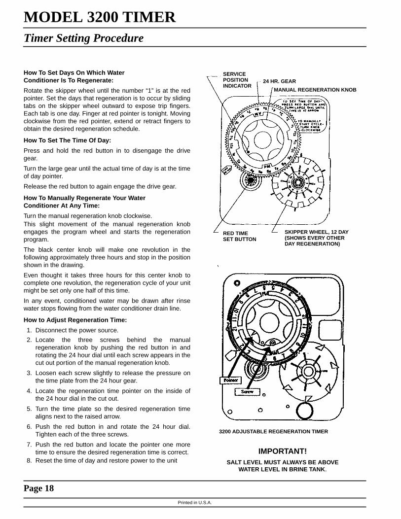
MODEL 3200 TIMERTimer Setting Procedure
How To Set Days On Which WaterConditioner Is To Regenerate:
Rotate the skipper wheel until the number “1” is at the redpointer. Set the days that regeneration is to occur by slidingtabs on the skipper wheel outward to expose trip fingers.Each tab is one day. Finger at red pointer is tonight. Movingclockwise from the red pointer, extend or retract fingers toobtain the desired regeneration schedule.
How To Set The Time Of Day:
Press and hold the red button in to disengage the drivegear.
Turn the large gear until the actual time of day is at the timeof day pointer.
Release the red button to again engage the drive gear.
How To Manually Regenerate Your WaterConditioner At Any Time:
Turn the manual regeneration knob clockwise.This slight movement of the manual regeneration knobengages the program wheel and starts the regenerationprogram.
The black center knob will make one revolution in thefollowing approximately three hours and stop in the positionshown in the drawing.
Even thought it takes three hours for this center knob tocomplete one revolution, the regeneration cycle of your unitmight be set only one half of this time.
In any event, conditioned water may be drawn after rinsewater stops flowing from the water conditioner drain line.
How to Adjust Regeneration Time:
1. Disconnect the power source.
2. Locate the three screws behind the manualregeneration knob by pushing the red button in androtating the 24 hour dial until each screw appears in thecut out portion of the manual regeneration knob.
3. Loosen each screw slightly to release the pressure onthe time plate from the 24 hour gear.
4. Locate the regeneration time pointer on the inside ofthe 24 hour dial in the cut out.
5. Turn the time plate so the desired regeneration timealigns next to the raised arrow.
6. Push the red button in and rotate the 24 hour dial.Tighten each of the three screws.
7. Push the red button and locate the pointer one moretime to ensure the desired regeneration time is correct.
8. Reset the time of day and restore power to the unitIMPORTANT!
SALT LEVEL MUST ALWAYS BE ABOVEWATER LEVEL IN BRINE TANK.
RED TIMESET BUTTON
SKIPPER WHEEL, 12 DAY(SHOWS EVERY OTHERDAY REGENERATION)
MANUAL REGENERATION KNOB
24 HR. GEARSERVICEPOSITIONINDICATOR
3200 ADJUSTABLE REGENERATION TIMER

Printed in U.S.A.
Page 19
MODEL 3200 & 3210 TIMER SERIESRegeneration Cycle Program Setting Procedure
How To Set Regeneration Cycle Program:
The regeneration cycle program on your water conditionerhas been factory preset, however, portions of the cycle orprogram may be lengthened or shortened in time to suitlocal conditions.
3200 & 3210 Series Timers (Figure to Right)
To expose cycle program wheel, grasp timer in upper left-hand corner and pull, releasing snap retainer andswinging timer to the right
To change the regeneration cycle program, the programwheel must be removed. Grasp program wheel andsqueeze protruding lugs toward center, lift program wheeloff timer. (Switch arms may require movement to facilitateremoval.)
Return timer to closed position engaging snap retainer inback plate. Make certain all electrical wires locate abovesnap retainer post
Timer Setting Procedure for 3200 & 3210 Timer
How To Change The Length Of The Backwash Time:
The program wheel as shown in the drawing is in theservice position. As you look at the numbered side of theprogram wheel, the group of pins starting at zerodetermines the length of time your unit will backwash.
FOR EXAMPLE: If there are six pins in this section, thetime of backwash will be 12 min. (2 min. per pin). Tochange the length of backwash time, add or remove pinsas required. The number of pins times two equal thebackwash time in minutes.
How To Change The Length Of Brine And Rinse Time:
The group of holes between the last pin in the backwashsection and the second group of pins determines thelength of time that your unit will brine and rinse (2 min. perhole).
To change the length of brine and rinse time, move therapid rinse group of pins to give more or fewer holes in thebrine and rinse section. Number of holes times twoequals brine and rinse time in minutes.
How To Change The Length Of Rapid Rinse:
The second group of pins on the program wheeldetermines the length of time that your water conditionerwill rapid rinse (2 min. per pin).
To change the length of rapid rinse time, add or removepins at the higher numbered end of this section asrequired. The number of pins times two equals the rapidrinse time in minutes.
How To Change The Length Of Brine Tank Refill Time:
The second group of holes in the program wheeldetermines the length of time that your water conditionerwill refill the brine tank (2 min. per hole).
To change the length of refill time, move the two pins atthe end of the second group of holes as required.
The regeneration cycle is complete when the outermicroswitch is tripped by the two pin set at end of thebrine tank refill section. The program wheel, however, willcontinue to rotate until the inner microswitch drops intothe notch on the program wheel.
BRINE & RINSESECTION(2 MIN. PER HOLE)
PIN STORAGE
BACK WASHSECTION(2 MIN. PER PIN)
BRINETANKREFILLSECTION(2 MIN.PERHOLE)
PROGRAMWHEEL FORCONTROL OFREGENERATIONCYCLE
RAPIDRINSESECTION(2 MIN.PER PIN)

Printed in U.S.A.
Page 20
MODEL 3210 ECONOMINDER™
Commercial Demand Regeneration Control Timer Settings
Typical Programming Procedure
Calculate the gallon capacity of the system, subtract thenecessary reserve requirement and set the gallonsrequired by lifting the gallon dial and rotating it so that thenumber of gallons required is aligned with the white doton program wheel gear. Release and check for firmengagement with gear. Note, drawing shows 8,750 gallonsetting. The capacity (gallons) arrow denotes remaininggallons exclusive of fixed reserve.
Note:
To set meter capacity at initial start-up, either:
1. Rotate manual regeneration knob one full revolution.— or —
2. Rotate program wheel manually clockwise or counterclockwise and align white dot with capacity arrow.
This procedure must be followed any time the programwheel setting is changed.
How To Set The Time Of Day:
Press and hold the red button in to disengage the 24 hourgear.
Turn the 24 hour gear until the actual time of day is at thetime of day pointer.
Release the red button to again engage the 24 hour gear.
How To Manually Regenerate Your Water ConditionerAt Any Time:
Turn the manual regeneration knob clockwise one “click”
This slight movement of the manual regeneration knobengages the program wheel and starts the regenerationprogram.
The black center knob will make one revolution in thefollowing approximately three hours and stop in theposition shown in the drawing.
Even though it takes three hours for this center knob tocomplete one revolution, the regeneration cycle of yourunit might be set for only one half of this time.
In any event, conditioned water may be drawn after rinsewater stops flowing from the water conditioner drain line.
Immediate Regeneration Timers:
These timers do not have a 24 hour gear. Setting thegallons on the program wheel and manual regenerationprocedure are the same as previous instructions.
*24 HOURGEAR
MANUALREGENERATIONKNOB
PROGRAMWHEEL
GALLONS LABELWHITE DOT
RED TIMESET
SERVICEPOSITIONINDICATOR
BUTTON
* Immediate regeneration timers do not have 24 hour gear. No time of day can be set.

Printed in U.S.A.
Page 21
MODEL 3900Service Instructions
PROBLEM CAUSE CORRECTION
1. Softener fails to regenerate. A. Electrical service to unit has beeninterrupted.
B. Timer is defective.
C. Power Failure.
A. Assure permanent electricalservice (check fuse, plug, pullchain or switch).
B. Replace timer.
C. Reset Time of Day.
2. Hard water. A. By-pass valve is open.
B. No salt in brine tank.
C. Insufficient water flowing intobrine tank.
D. Hot water tank hardness.
E. Leak at distributor tube.
F. Internal valve leak.
A. Close by-pass valve.
B. Add Salt to brine tank andmaintain salt level above waterlevel.
C. Check brine tank fill time andclean brine line flow control ifplugged.
D. Repeated flushing of the hot watertank is required.
E. Make sure distributor tube is notcracked. Check O-ring and tubepilot.
F. Replace seals and spacers and/orpiston.
3. Unit used too much salt. A. Improper salt setting.
B. Excessive water in brine tank.
A. Check salt usage and salt setting.
B. See Problem No. 7.
4. Loss of water pressure. A. Iron buildup in line to waterconditioner.
B. Iron buildup in water conditioner.
C. Inlet of control plugged due toforeign material broken loose frompipe by recent work done onplumbing system.
A. Clean line to water conditioner.
B. Clean control and add mineralcleaner to mineral bed. Increasefrequency of regeneration.
C. Remove pistons and cleancontrol.
5. Loss of mineral through drain line. A. Air in water system.
B. Improperly Sized Drain Line FlowControl.
A. Assure that well system hasproper air eliminator control.Check for dry well condition.
B. Check For proper Drain Rate.
6. Iron in conditioned water. A. Fouled mineral bed. A. Check backwash, brine draw andbrine tank fill. Increase frequencyof regeneration. IncreaseBackwash Time.
7. Excessive water in brine tank A. Plugged drain line flow control.
B. Plugged injector system.
C. Timer not cycling.
A. Check flow control.
B. Clean injector and screen.
C. Replace timer.

Printed in U.S.A.
Page 22
MODEL 3900Service Instructions
General Service Hints For Meter Control
Problem: Softener Delivers Hard Water.
Cause could be that. . .Reserve Capacity Has Been Exceeded.
Correction: Check salt dosage requirements and reset program wheel to provide additional reserve.Cause could be that. . .Program Wheel Is Not Rotating With Meter Output.
Correction: Pull cable out of meter cover and rotate manually. Program wheel must move without binding and clutchmust give positive “clicks” when program wheel strikes regeneration stop. If it does not, replace timer. Cause could bethat. . .Meter Is Not Measuring Flow.
Correction: Check meter with meter checker.
D. Foreign material in brine valve.
E. Foreign material in brine line flowcontrol.
D. Replace brine valve seat andclean valve.
E. Clean brine line flow control.
8. Softener fails to draw brine. A. Drain line flow control is plugged.
B. Injector is plugged.
C. Line Pressure Is Too Low.
D. Internal Control Leak.
E. Service Adapter Did Not Cycle.
A. Clean drain line flow control.
B. Clean injector.
C. Increase Line Pressure To 20P.S.I. Minimum.
D. Change Seals, Spacers andpiston Assembly.
E. Check Drive Motor And Switches
9. Control cycles continuously. A. Missadjusted, Broken or shortedSwitch.
A. Determine if switch or timer isfaulty and replace it, or replacecomplete power head.
10. Drain flows continuously. A. Valve is not programmingcorrectly.
B. Foreign material in control.
C. Internal control leak.
A. Check timer program andpositioning of control. Replacepower head assembly if notpositioning properly.
B. Remove power head assemblyand inspect bore, remove foreignmaterial and check control invarious regeneration positions.
C. Replace seals and pistonassembly.
PROBLEM CAUSE CORRECTION

Printed in U.S.A.
Page 23
3900 SYSTEM #4Valve Wiring

Printed in U.S.A.
Page 24
3900 System #4 With Remote MeterValve Wiring

Printed in U.S.A.
Page 25
3900 SYSTEM #5Valve Wiring

Printed in U.S.A.
Page 26
3900 SYSTEM #6Valve Wiring

Printed in U.S.A.
Page 27
3900 SYSTEM #7Valve Wiring

Printed in U.S.A.
Page 28
3900 MULTIVALVE SYSTEM #7Valve Wiring

Printed in U.S.A.
Page 29
MODEL 3900System #4 - Typical Single Tank Installation with Optional Meter
System #5 Interlock - Typical Twin Tank Installationwith Optional Meter Interlock and No Hard Water Bypass
DRAIN
BRINE LINE
BRINETANK
RESINTANK
3 WIREPOWER CORD
MANUALSHUT-OFF
OUT
IN
OPTIONAL3900 METER
DRAIN
BRINE LINE
BRINE TANK
RESIN TANKUNIT 2
BRINE TANK
ELECTRICALINTERLOCKCORD
3 WIREPOWER CORD
MANUALSHUT-OFF
RESIN TANKUNIT 1
OUT
IN
Printed in U.S.A.
Page 30
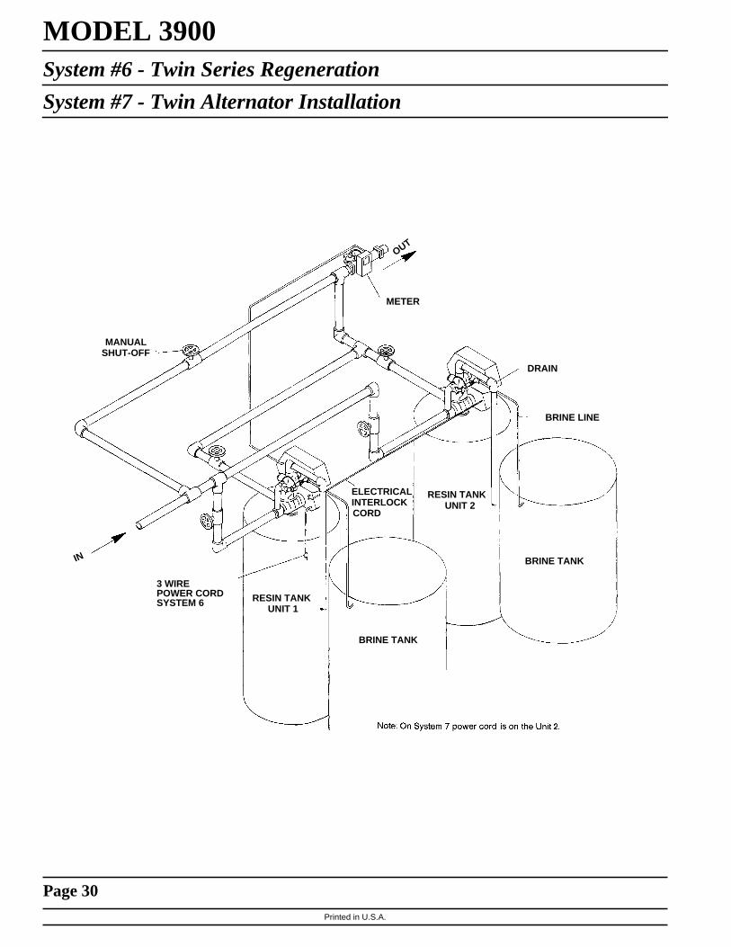
MODEL 3900System #6 - Twin Series Regeneration
System #7 - Twin Alternator Installation
OUT
METER
DRAIN
BRINE LINE
BRINE TANK
RESIN TANKUNIT 2
ELECTRICALINTERLOCKCORD
BRINE TANK
RESIN TANKUNIT 1
3 WIREPOWER CORDSYSTEM 6
MANUALSHUT-OFF
IN

Printed in U.S.A.
Page 31
MODEL 3900Flow Data & Injector Draw Rates

Printed in U.S.A.
Page 32
MODEL 3900*Typical Timer Settings

Printed in U.S.A.
Page 33
MODEL 3900Service Assemblies
60036-02 . . . . . . 1800 Brine ValveSee Illustration Page 12
1 . . . . . 11772 . . . . . . . . . Spring1 . . . . . 11774 . . . . . . . . . Retaining Ring1 . . . . . 18713 . . . . . . . . . Brine Valve Body1 . . . . . 16497-01. . . . . . . Brine Stem Assembly1 . . . . . 16498-01. . . . . . . Stem Guide Assembly
60277. . . . . . . . 1800 Injector AssemblySee Illustration Page 12
4 . . . . . 12473 . . . . . . . . . Screw - Hex Hd.1 . . . . . 15127 . . . . . . . . . Injector Throat1 . . . . . 15128 . . . . . . . . . Injector Nozzle2 . . . . . 15246 . . . . . . . . . O-Ring -1161 . . . . . 16340 . . . . . . . . . Injector Body1 . . . . . 16341-01. . . . . . . Injector Cover
60106-00 . . . . . 3900 Upper Piston AssemblySee Illustration Page 6
1 . . . . . 14818 . . . . . . . . . Clip Piston Rod1 . . . . . 14922 . . . . . . . . . O-Ring - 0351 . . . . . 15125 . . . . . . . . . Piston Rod1 . . . . . 16130 . . . . . . . . . Piston1 . . . . . 16398-0 . . . . . . . . End Plug Assembly
60107-00 . . . . . 3900 Lower Piston - HardWater By-PassSee Illustration Page 6
1 . . . . . 14818 . . . . . . . . . Clip Piston Rod1 . . . . . 16071 . . . . . . . . . Piston1 . . . . . 16072 . . . . . . . . . Piston Rod1 . . . . . 16076 . . . . . . . . . O-Ring - 0421 . . . . . 16399-01 . . . . . . . End Plug Assembly - White
60107-10 . . . . . 3900 Lower Piston - No HardWater By-PassSee Illustration Page 6
1 . . . . . 14818 . . . . . . . . . Clip Piston Rod1 . . . . . 16082 . . . . . . . . . Piston - No Hard Water
By-Pass1 . . . . . 16072 . . . . . . . . . Piston Rod1 . . . . . 16076 . . . . . . . . . O-Ring - 0421 . . . . . 16399-11 . . . . . . . End Plug Assembly - Black
60131 . . . . . . . 3900 Upper Seal KitSee Illustration Page 6
2. . . . . . . 10368 . . . . . . . Spacer5. . . . . . . 10369 . . . . . . . Spacer - Port8. . . . . . . 11720 . . . . . . . Seal
60132. . . . . . . . 3900 Lower Seal KitSee Illustration Page 6
4. . . . . . . 16068. . . . . . . . Seal2. . . . . . . 16069. . . . . . . . Spacer - Narrow1. . . . . . . 16070. . . . . . . . Spacer - Wide
60132-01 . . . . . 3900 Lower Seal Kit, HotWater
4. . . . . . . 16068. . . . . . . . Seal2. . . . . . . 16069-01 . . . . . Spacer, Narrow, Hot Water1. . . . . . . 16070-01 . . . . . Spacer, Wide, Hot Water
60057-01 . . . . . 3900 Upper Drive MotorAssembly - 115 V.See Illustration Page 8
4. . . . . . . 10302. . . . . . . . Insulator - Switch3. . . . . . . 10872. . . . . . . . Screw - Hex Hd.1. . . . . . . 11080. . . . . . . . Screw - Flat Hd.3. . . . . . . 10218. . . . . . . . Switch2. . . . . . . 10300. . . . . . . . Screw - Hex Hd.1. . . . . . . 15120. . . . . . . . Bracket - Motor Mounting1. . . . . . . 16044. . . . . . . . Drive Motor - 115 V.1. . . . . . . 16052. . . . . . . . Bushing1. . . . . . . 17797. . . . . . . . Bracket - Switch Mounting2. . . . . . . 12624. . . . . . . . Screw - Pan Hd.
60058-01 . . . . . 3900 Lower Drive MotorAssembly - 115 V.System #4See Illustration Page 10
2. . . . . . . 10302. . . . . . . . Insulator - Switch3. . . . . . . 10872. . . . . . . . Screw - Hex Hd.1. . . . . . . 11080. . . . . . . . Screw - Flat Hd.1. . . . . . . 10218. . . . . . . . Switch2. . . . . . . 10300. . . . . . . . Screw - Hex Hd.2. . . . . . . 11805. . . . . . . . Screw - Pan Hd.1. . . . . . . 16044. . . . . . . . Drive Motor - 115 V.1. . . . . . . 17797. . . . . . . . Bracket - Switch Mounting1. . . . . . . 16086. . . . . . . . Bracket - Motor Mounting

P/N 16505 Rev. 2 3/00 Printed 3/00