Embed Size (px)
Citation preview
--------------------- - ----------- JICABlf '99 ,-- - - --,
A9,2O n-sit e A C test after installation for long HV and EHV cablesVAN SCHAIK N., DE L1GT c.. PULTRUM E., Kema, Arnhem, The Netherlands
RésuméLe but des tests effectués aprés l'installation denouveaux circuits câblés est de vérifier leur" aptitude à l'emploi ". Les tests sont concentrés surles accessoires. Le câble en soi a déjà été testé enusine. Les tests sur site de circuits câblés qui sont enservice depuis longtemps sont effectués dans le butde vérifier l'état du circuit, câble compris. Ces testsdoivent être efficaces sans toutefo is endommager lecircuit testé. Les tests de tension de C.C. se sontavérés inefficaces et dangereux pour les câblesXLPE. Des tests de tension de C.A. effectués sursile sont actuellement disponibles grâce à l'existenced'équipements de résonnance transportables,montés en série, qui peuvent également s'utiliserpour les câbles à trés haute tens ion. Les originesdes tests de C.A., la configuration des circuits et desexpériences seront abordées .
Introduction and background
The test alter installation of long lengths of mediumvoltage, high voltage and extra high voltage cablesand their accessories serve as a tool to assistnetwork owners to prevent unexpected outages .Less unexpected outages mean less costs and noloss of reputation (for the network owner and for themanufacturer). Purpose of on-site tests alterinstallation is to detect defects in assembledaccessories in new cable circuits and to check thereliability of accessories and of cables in serviceaged circuits. On-site tests should be effective butnot cause any damage to the circuit under test.
Quality assurance is very important both duringproduction as weil installation. However, qualityassurance will not assure detection of ail defectsarising during installation and during assembly of theaccessories [1 , 2]. Such defects have to be detectedby tests and measurements. However one countryrelies completely on quality control on site, incombination with an intensive pre-qualification andtraining programme [20] .
DC voltage tests on oil pressure paper cablesystems are generally accepted. For polymericcables the situation is quite differe nt [3]. "DC tests onXLPE cable systems have been shown to be very
AbstractTests alter installation of new cable systems havethe purpose to check the "fitness for use". The testfocuses on the accessories. The cable itself wasalready tested at the factory. On-site tests on serviceaged cable circuit have the purpose to check thecondition of the circuit, including the cable. On-sitetests should be effective but not harmful to the circuitunder test. DC voltage tests have been shown to beineffective and harmful for XLPE cables. ACwithstand voltage tests on-site has become availablebecause of the existence nowadays of transportableseries resonant equipment, also for extra highvoltages. Background of ac testing, system set-upand experiences will be discussed.
ineffective, far from represen tative and evendangerous for the circuit under test. AC voltagewithstand testing at levels of 2Uo to 3Uo give themost reliable results . The alternative using thesystem voltage Uo during one week apparently is stilltoo weak and olten cannot detect defects which havebeen found by short time ac voltage tests at highervo ltage levels". This is the conclusion of a Cigré1990 report [4]. This conc lusion is still valid [5, 6].
The effectiveness of the ac test method has beendemonstrated by field tests and research [1 , 10, 11].Test requirements are dete rmined by the maximumallowable field stress. The test duration is coupled tothe maximum allowable test voltage . Theeffectiveness of the test can be improved byincluding part ial discharge measurement wheneverposs ible [1, 11, 12, 13, 14].
Nowadays tests alter installation are offered basedon the series resonant principle, for MV, HV andEHV circuits . MV circuits can be tested up to 55 kVtest voltage. HV circuits with a rated voltage up to220 kV and with circuit lengths up to 25 km, can betested with ac voltage up to 254 kV. Systems with ahigher rated voltage can be tested up to 6,5 kmlength (XLPEIGIL) up to 504 kV. Because of the factthat these systems are based on the series resonantprinciple , either the freque ncy or the inductance
291
Close and Return
292
value will depend on the value of the totalcapacitance of the cable circu it. Acceptedfrequencies are of course power frequency andfrequencies in a wider range of 25 Hz (for longlengths) till 300 Hz (for short lengths ).
Experience gained since 1997 with the Dutch testsets applied on HV cables in the Netherlands ,Germany, Belgium and the UK will be reported. Alsoin Switzerl and and in South Africa test sets are inoperation [7, 8, 9].
AC test methods
For long lengths , three methods are available . The0,1 Hz withstand test so far is only applicable for MVcircuits. The Iwo other methods are using the systemvoltage itself or using series resonant test sets. Aseries resonant test set cons ists of a reactor eitherwith an adjustable inductance or a fixed inductance.These Iwo methods are applicable for MV, HV andEHV circu its.
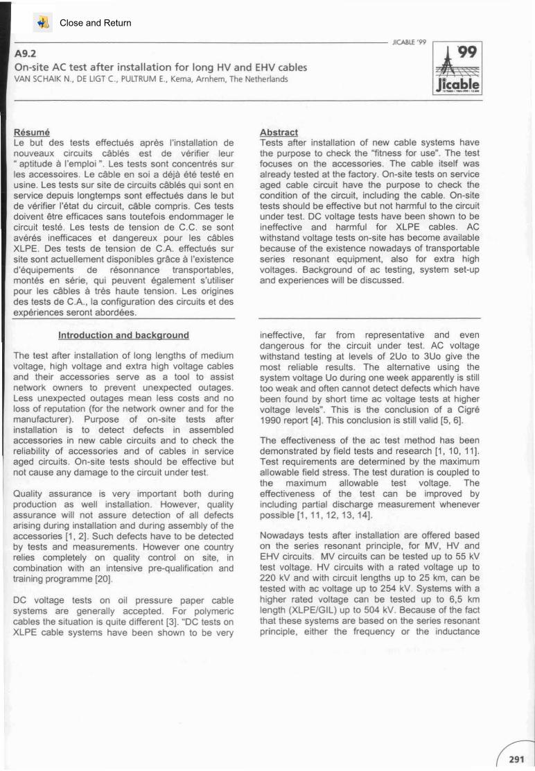
AC test ing using system vol tage ln principle, thenelwork owner can test the cable with its own ACsystem voltage . In the early days this was the onlyac method applicable. One can make use of thephase to neutral voltage (Uo) or of the phase-tcphase voltage (U=l ,7Uo). In case the nelworktransformer has an insulated neutra l, the phase-tophase voltage can be applied by connecting one ofthe phases to ground (one alte r another), seefigure 1 [15].
..-rr.roc
Figure 1 AC voltage test, 50 Hz, making use of thephase-to-phase voltage U = 1,7Uo
The advantage of this method is that the networkowner can do this test at a conven ient time.
Disadvantage is that during breakdown, the nelworkwill be subjected to fast transient voltages, whichmay be harmful. Moreover, the short circuit poweravailable during the test is the short circuit power ofthe nelwork. Th is short circuit power can be limitedsomewhat by feed ing the high-voltage transformerthrough its distribution section. The protection systemhas to be set to the test condit ions in such a way thatthe amount of power during breakdown is Iimited [15,16]. For these reasons this test method has somerisks and is not always preferred .
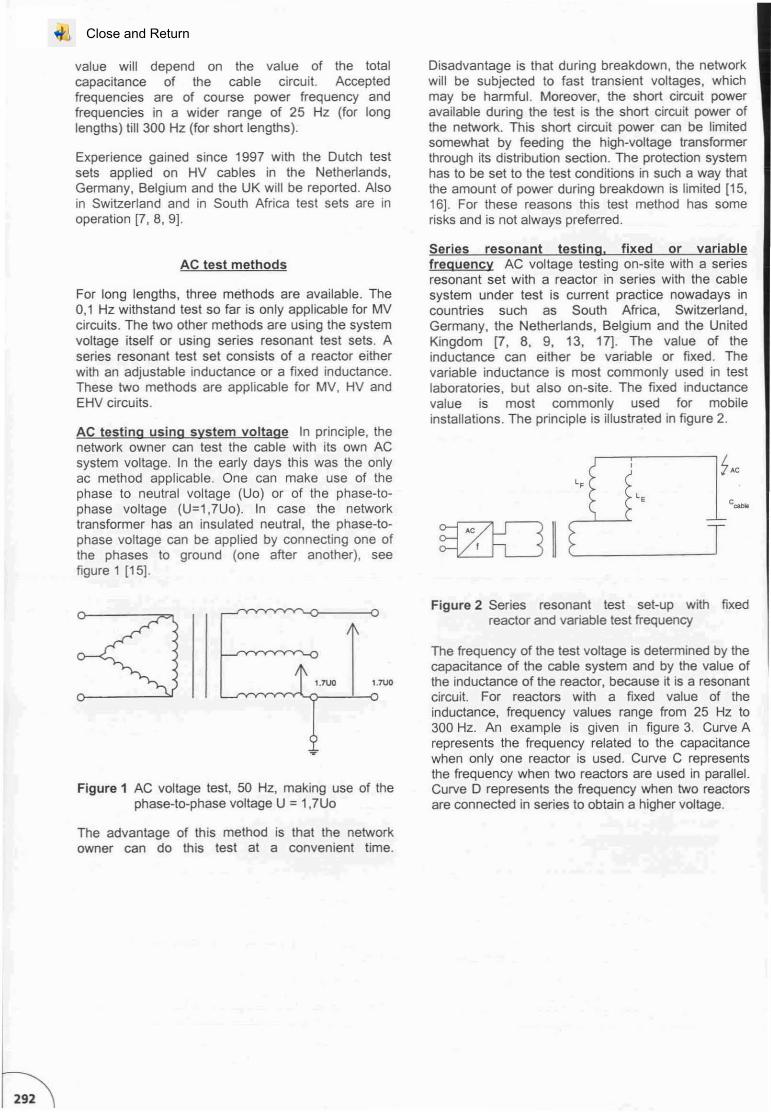
Ser ies resonant testi na. fixed or variablefreguency AC voltage testing on-site with a seriesresonan t set with a reactor in series with the cablesystem under test is current practice nowadays incountr ies such as South Africa, Switzerland,Germany, the Netherlands, Belgium and the UnitedKingdom [7, 8, 9, 13, 17J. The value of theinductance can either be var iable or fixed. Thevariable inductance is most com monly used in testlaboratories, but also on-site. The fixed inductancevalue is most common ly used for mobileinstallations. The principle is illustrated in figure 2.
LE
@QIIFigure 2 Series resonant test set-up with fixed
reactor and variable test frequency
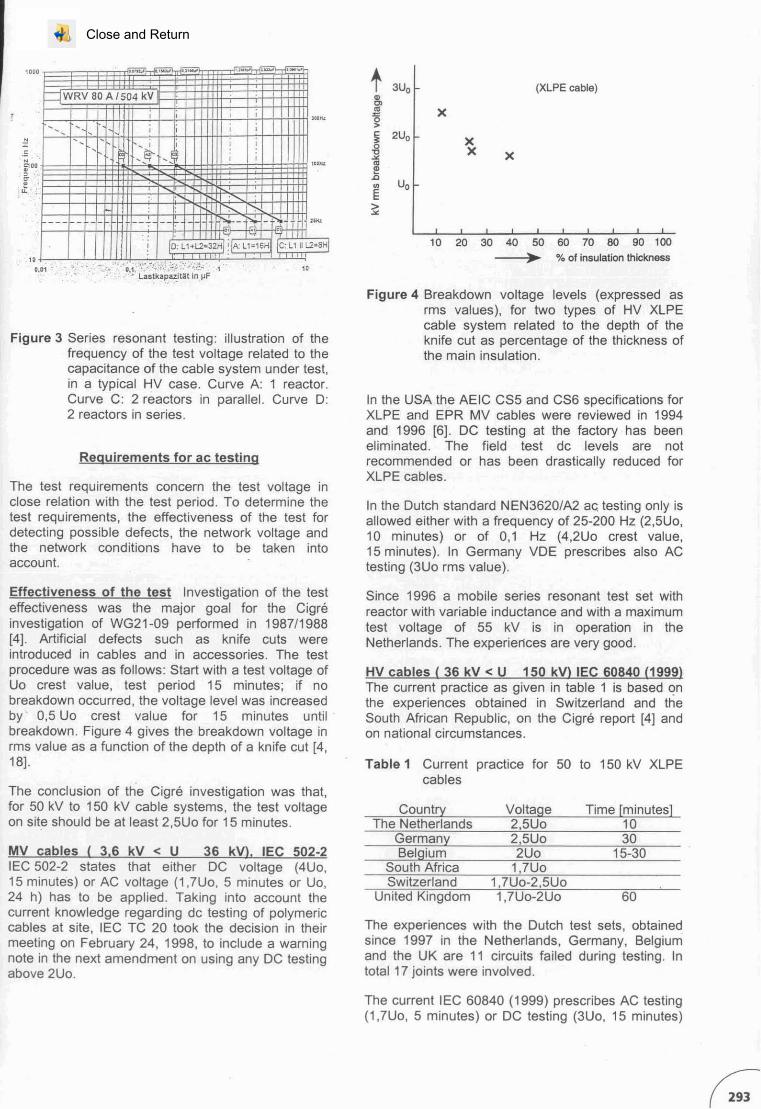
The frequency of the test voltage is determined by thecapacitance of the cable system and by the value ofthe inductance of the reactor , because it is a resonantcircuit. For reactors with a fixed value of theinductance, frequency values range from 25 Hz to300 Hz. An example is given in figure 3. Curve Arepresents the frequency related to the capacitancewhen only one reactor is used. Curve C representsthe frequency when Iwo reactors are used in parallel.Curve D represents the frequency when Iwo reactorsare connected in series to obtain a higher voltage.
Close and Return
t 3Uo (XLPE cable)œ'"'" X~
~
§ 2Uo X0 X'C X~
'"~Uo0
E>~
10 20 30 40 50 60 70 80 90 100
., % of insulation thickness
P.._ IJ
c ,,~ ,,- .,..... ,- ._....
,:fWRV ao A /504 kV
, , , ;lOGH,-- - ; ; , ,
1- -1
-- - , , !,-- !f- -- , ,
'"1I.lc
, r-,--- - - --- -- ","- - ".. - 1
,,~
-ft " ", 0: L1+L2; 32H ilA: 11"16H le: L1 Il L2;8HI
.>~.~:.::.- ~.(~~;.;~~:~ 'lii~'~ ;'~~~:~ ~ ,.."G,D1 .;'"
".
Figure 3 Series resonant test ing: illustrat ion of thefrequency of the test voltage related to thecapaci tance of the cable system under test,in a typical HV case . Curve A: 1 reactor .Curve C: 2 reac tors in parallel. Curve 0 :2 reactors in series .
Requirements for ac testinq
The test requirements concern the test voitage inciose relation with the test period . To determine thetest requirements, the effecliveness of the test fordetecting possible defects, the network voltage andthe network condi tions have to be taken intoaccount.
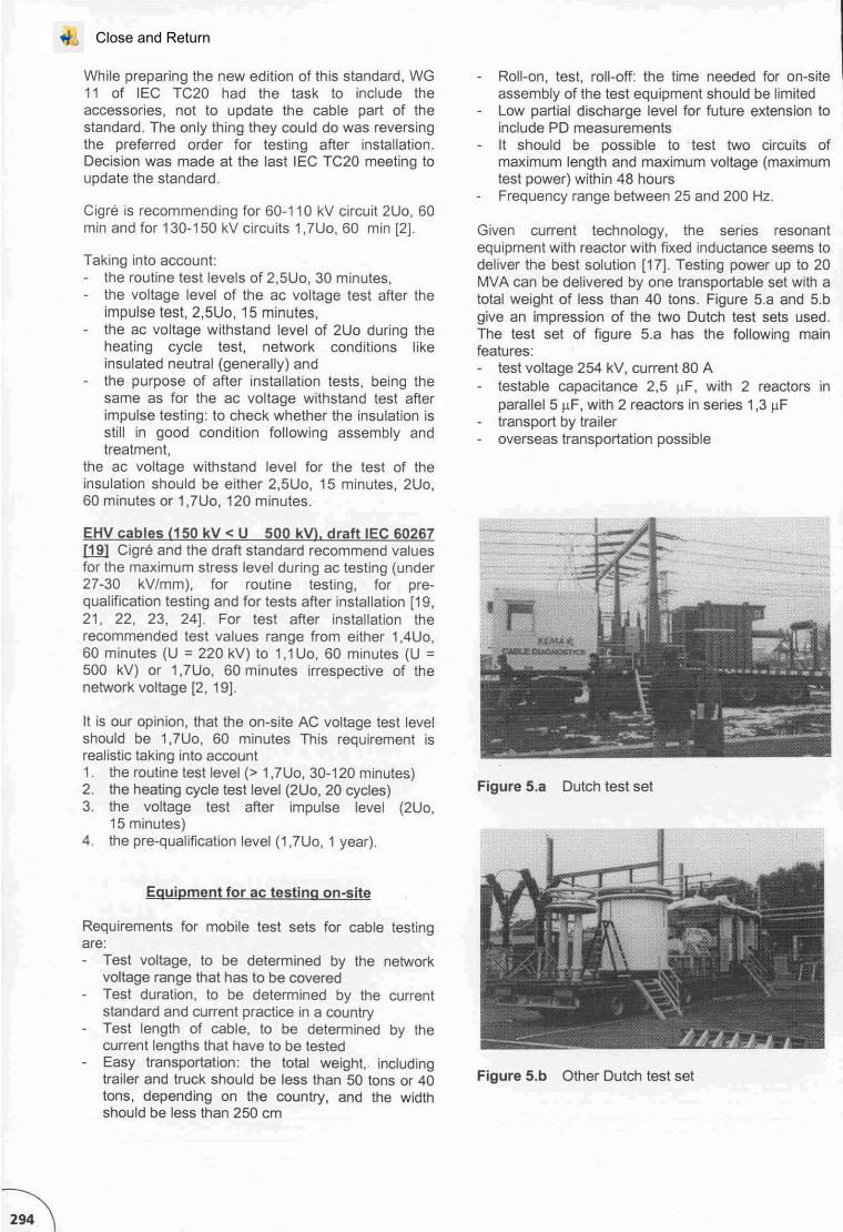
Figure 4 Breakdown voilage leve ls (expressed asrms values), for two types of HV XLPEcable system related to the depth of theknife cut as percentage of the thickness ofthe main insu lation.
ln the USA the AEIC CS5 and CS6 spec ifications forXLPE and EPR MV cables were rev iewed in 1994and 1996 [6]. OC testing at the facto ry has beeneliminated. The field test dc levels are notrecommended or has been drastically reduced forXLPE cables .
ln the Outch standard NEN3620/A2 ac; testing only isallowed eithe r with a frequency of 25-200 Hz (2,5Uo,10 minutes) or of 0,1 Hz (4,2Uo crest value,15 minutes). In Germany VOE prescribes also ACtesting (3Uo rms value).
Table 1 Current practice for 50 to 150 kV XLPEcables
The experiences with the Dutch test sets, obtainedsince 1997 in the Netherlands, Germany, Belgiurriand the UK are 11 circu its failed during test ing. Intotal 17 joints were involved.
Since 1996 a mobile series resonant test set withreacto r with variable induc tance and with a maximumtest voltage of 55 kV is in operation in theNetherlands . The experiences are very good.
HV cables ( 36 kV < U 150 kVI IEC 60840 (1999)The current practice as given in table 1 is based onthe experiences obtained in Switzerland and theSouth Afr ican Republic, on the Cigré report [4] andon national circumstances.
60
1030
15-30
Time [minutes]
2,5Uo
1,7Uo
2,5Uo
2Uo
Voltage
1,7Uo-2Uo1,7Uo-2,5Uo
Belgium
Country
Germany
SwitzerlandSouth Africa
United Kingdom
The Netherlands
The conclusion of the Cigré investigation was that,for 50 kV to 150 kV cable systems, the test voltageon site should be atleast 2,5Uo for 15 minutes.
Effectiveness of the test Investigation of the testeffectiveness was the major goal for the Cigréinvestigation of WG21 -09 performed in 1987/1988[4]. Artificial defects such as knife cuts wereintroduced in cables and in accessories. The testprocedu re was as follows : Start wi th a test voilage ofUo crest value, test period 15 minutes; if nobreakdown occurred , the voltage level was increasedby 0,5 Uo crest value for 15 minutes until:breakdown. Figure 4 gives the breakdown voilage inrms value as a function of the depth of a knife cut [4,18].
MV cab les ( 3,6 kV < U 36 kVl. IEC 502-2IEC 502-2 states thal either OC voltage (4Uo,15 minutes ) or AC voltage (1,7Uo, 5 minutes or Uo,24 h) has to be appl ied . Taking into account thecurrent knowledge regarding dc testin g of polymericcables at site, IEC TC 20 took the decis ion in theirmeeting on February 24, 1998 , to include a warni ngnote in the next amendment on using any OC testingabove 2Uo.
The current IEC 60840 (1999) prescribes AC testing(1,7Uo, 5 minutes) or OC testing (3Uo , 15 minutes)
Close and Return
While preparing the new edition of this standard, WG11 of IEC TC20 had the task to include theaccessories, not to update the cable part of thestandard , The only thing they cou ld do was reversingthe preferred order for testing alter installation.Decision was made at the last IEC TC20 meeting toupdate the standard.
Cigré is recommending for 60-1 10 kV circuit 2Uo, 60min and for 130-150 kV circuit s 1,7Uo, 60 min [2].
Taking into account:the routine test levels of 2,5Uo, 30 minutes,the voltage leve l of the ac voltage test alte r theimpulse test , 2,5Uo , 15 minutes,the ac voltage withstand level of 2Uo during theheating cycle test, network conditions likeinsulated neutral (generally) andthe purpose of after installation tests, being thesame as for the ac voltage withstand test alterimpulse testing : to check whether the insulation isstill in good condition following assembl y andtreatment,
the ac voltage withstand level for the test of theinsulation should be either 2,5Uo, 15 minutes , 2Uo,60 minutes or 1,7Uo, 120 minutes.
EHV cables (150 kV < U 500 kVI, draft tEe 60267u.m Cigré and the dralt standard recommend valuesfor the maximum stress level during ac testing (under27-30 kY/mm), for routine testing, for prequalification testing and for tests alte r installation [19,21, 22, 23, 24] . For test alter installation therecommended test values range from either 1AU o,60 minutes (U = 220 kV) to 1,1Uo, 60 minutes (U =500 kV) or 1,7Uo, 60 minutes irrespective of thenetwork voltage [2, 19].
It is our opinion, that the on-s ite AC voltage test levelshould be 1,7Uo, 60 minutes This requirement isrealistic taking into account1. the rout ine test level (> 1,7Uo, 30-120 minutes)2. the heating cycle test level (2Uo, 20 cycles)3. the voltage test alter impulse level (2Uo,
15 minutes)4. the pre-qua lificat ion level (1,7Uo, 1 year).
Eguipment for ac testing on-site
Requirements for mobile test sets for cable testingare:
Test voltage, to be determined by the networkvoltage range that has to be coveredTest duration, to be determined by the currentstandard and current practice in a countryTest length of cable, to be determined by thecurrent lengths that have to be testedEasy transportation : the total weight,. includingtrailer and truck should be less than 50 tons or 40tons, depending on the country, and the widthshould be less than 250 cm
Roll-on, test, roll-off: the time needed for on-siteassembly of the test equipment should be limitedLow partial discharge level for future extension toinclude PD measurementsIt should be possible to :test two circuits ofmaximum length and maximum voltage (maximumtest power ) within 48 hoursFrequency range between 25 and 200 Hz.
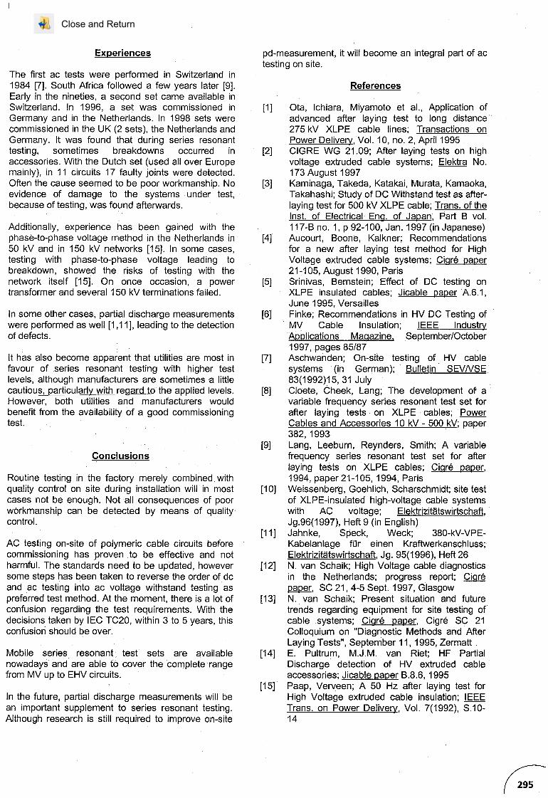
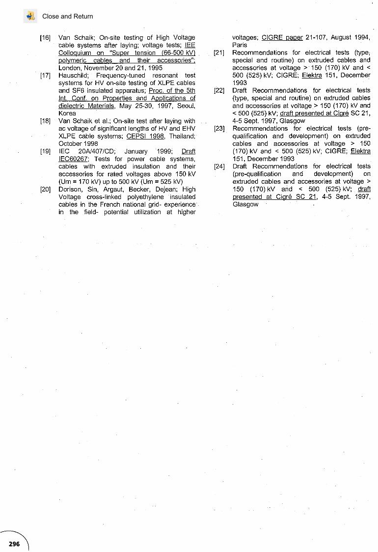
Given current technology, the series resonantequipment with reactor with fixed inductance seems todeliver the best solution [17] . Testing power up to 20MVA can be delivered by one transportable set with atotal weight of less than 40 tons. Figure 5.a and 5.bgive an impression of the two Dutch test sets used.The test set of figure 5.a has the following mainfeatures :
test voltage 254 kV, current 80 Atestable capacitance 2,5 flF, with 2 reactors inparallel 5 flF, with 2 reactors in series 1,3 flFtransport by traileroverseas transportation possible
Figure 5.a Dutch test set
Figure 5.b Other Dutch test set
Close and Return
Experiences
The first ac tests were performed in Switzerland in1984 [7]. South Africa followed a few years later [9].Early in the nineties, a second set came available inSwitzerland. In 1996, a set was commissioned inGermany and in the Netherlands. In 1998 sets werecommissioned in the UK (2 sets), the Netherlands andGermany. It was found that during series resonanttesting, sometimes breakdowns occurred inaccessories. With the Dutch set (used ail over Europemainly), in 11 circuits 17 faulty joints were detected.Often the cause seemed to be poor workmanship. Noevidence of damage ta the systems under test,because of testing, was found afterwards.
Additionally, experience has been gained with thephase-to-phase voltage method in the Netherlands in50 kV and in 150 kV networks [15]. In some cases,testing with phase-to-phase voltage leading tobreakdown, showed the risks of testing with thenetwork itself [15]. On once occasion, a powertransformer and several 150 kV terminations failed.
ln some other cases, partial discharge measurementswere performed as weil [1,11], leading to the detectionof defects.
It has also become apparent that utilities are most infavour of series resonant testing with higher testlevels, although manufacturers are sometimes a littlecautiou~~articul(3fly_with regard 10 the applied levels.However, both utilities and manufacturers wouldbenefit from the avallability of a good commissioningtest.
Conclusions
Routine testing in the factory merely combined withquality control on site during installation will in mostcases not be enough. Not ail consequences of poorwàrkmanship can be detected by means of qualitycontrol.
AC testing on-site of polymerie cable circuits beforecommissioning has proven to be effective and notharmful. The standards need to be updated, howeversome steps has been taken to reverse the order of deand ac testing into ac voltage withstand testing aspreferred test method. At the moment, there is a lot ofconfusion regarding the test requirements. With thedecisions taken by IEC TC20, within 3 to 5 years, thisconfusion should be over.
Mobile series resonant test sets are availablenowadays and are able to cover the complete rangefrom MV up to EHV circuits.
ln the future, partial discharge measurements will bean important supplement to series resonant testing.Although research is still required to improve on-site
pd-measurement, it will become an integral part of actesting on site.
References
[1] Ota, Ichiara, Miyamoto et al., Application ofadvanced after laying test to long distance275 kV XLPE cable lines; Transactions onPower Delivery, Vol. 10, no. 2, April 1995
[2] CIGRE WG 21.09; After laying tests on highvoltage extruded cable systems; Elektra No.173 August 1997
[3] Kaminaga, Takeda, Katakai, Murata, Kamaoka,Takahashi; Study of OC Withstand test as afterlaying test for 500 kV XLPE cable; Trans. of theInst.. of Electrical' Eng. of Japan, Part B vol.117-B no. 1, p 92-100, Jan. 1997 (in Japanese)
[4] Aucourt, Boone, Kalkner; Recommendationsfor a new afterlaying test method for HighVoltage extruded cable systems; Cigré paper21-105, August 1990, Paris
[5] Srinivas, Bernstein; Effect of OC testing onXLPE insulated cables; Jicable paper A.6.1,June 1995, Versailles
[6] Finke; Recommendations in HV OC Testing ofMV Cable Insulation; IEEE IndustryApplications Magazine, September/October1997, pages 85/87
[7] Aschwanden; On-site testing of HV cablesystems (in German); Bulletin SEVNSE83(1992)15, 31 July
[8] Cloete, Cheek, Lang; The development of avariable frequency series resonant test set forafter laying tests on XLPE cables; PowerCables and Accessories 10 kV - 500 kV; paper382, 1993
[9] Lang, Leeburn, Reynders, Smith; A variablefrequency series r.esonant test set for afterlaying tests on XLPE cables; Cigré paper,1994, paper 21-105,1994, Paris
[10] Weissenberg, Goehlich, Scharschmidt; site testof XLPE-insulated high-voltage cable systemswith AC voltage; Elektrizitatswirtschaft,Jg.96(1997), Heft 9 (in English)
[11] Jahnke, Speck, Weck; 380-kV-VPE-Kabelanlage für einen Kraftwerkanschluss;Elektrizitatswirtschaft,Jg. 95(1996), Heft 26
[12] N. van Schaik; High Voltage cable diagnosticsin the Netherlands; progress report; Cigré~, SC 21,4-5 Sept. 1997, Glasgow
[13] N. van Schaik; Present situation and futuretrends regarding equipment for site testing ofcable systems; Cigré paper, Cigré SC 21Colloquium on "Diagnostic Methods and AfterLaying Tests", September 11, 1995, Zermatt
[14] E. Pultrum, M.J.M. van Riet; HF PartialDischarge detection of HV extruded cableaccessories; Jicable paper B.8.6, 1995
[15] Paap, Verveen; A50 Hz after laying test forHigh Voltage extruded cable insulation; IEEETrans. on Power Delivery, Vol. 7(1992), S.1014
Close and Return
[16] Van Schaik; On-site testing of High Voltagecable systems after laying; voltage tests; IEEColloquium on "Super tension (66-500 kV)polymeric cables and their accessories";London, November 20 and 21, 1995
[17] Hauschild; Frequency-tuned resonant testsystems for HV on-site testing of XLPE cablesand SF6 insulated apparatus; Proc. of the 5thInt. Conf. on Properties and Applications ofdielectric Materials, May 25-30, 1997, Seoul,Korea
[18] Van Schaik et al.; On-site test after laying withac voltage of significant lengths of HV and EHVXLPE cable systems; CEPSI 1998, Thailand;October 1998
[19] IEC 20A/407/CD; January 1999; DraftIEC60267; Tests for power cable systems,cables with extruded insulation and theiraccessories for rated voltages above 150 kV(Um = 170 kV) up to 500 kV (Um = 525 kV)
[20] Dorison, Sin, Argaut, Becker, Dejean; HighVoltage cross-Iinked polyethylene insulatedcables in the French national grid- experfencein the field- potential utilization at higher
voltages; CIGRE paper 21~107, August 1994,Paris
[21] Recommendations for electrical tests (type,special and routine) on extruded cables andaccessories at voltage> 150 (170) kV and <500 (525) kV; CIGRE; Elektra 151, December1993
[22] Draft Recommendations for electrical tests(type, special and routine) on extruded cablesand accessories at voltage> 150 (170) kVand< 500 (525) kV; draft presented at Cigré SC 21,4-5 Sept. 1997, Glasgow
[23] Recommendations for electrical tests (prequalification and development) on extrudedcables and accessories at voltage > 150(170) kV and < 500 (525) kV; CIGRE; Elektra151, December 1993
[24] Draft Recommendations for electrical tests(pre-qualification and development) onextruded cables and accessories at voltage >150 (170) kV and < 500 (525) kV; draftpresented at Cigré SC 21, 4-5 Sept. 1997,Glasgow
Close and Return