Embed Size (px)
Citation preview

66250308-EN - V1.0 - 18/01/18 - 1 -SP300-1 & SP301-1C - Installation Instructions
Vandal Resistant VX2200 Digital Range ENGSP300-1 & SP301-1C Audio/Video Digital Front Panel
DIGITAL FRONT PANEL
140 mm
280
mm
140 mm
400
mm
179 mm 80 mm
319
mm
179 mm 80 mm
439
mm
Fig. 1 - Front View
VRDBB140x280
VRDBB140x400
SP300-1 SP301-1C

66250308-EN - V1.0 - 18/01/18 - 2 -SP300-1 & SP301-1C - Installation Instructions
Vandal Resistant VX2200 Digital Range
SP300-1 & SP301-1C Audio/Video Digital Front Panel
Art. 130
1
7
1213
1110
8
5
4
3
2
14
9
1
2
3
4
5
6
7
8
9
10
11
12
13
Wide angle camera
JP1 = video signal modeJP2 = camera switching mode
Camera terminal connections:SL, SB, V2, V1, V, -, SB, +20, +12
Speechboard volume controls
Speaker module
Digital display window
Main 2200-1-pcb
VX2200 pcb terminal connections:GND, +12, -, L, BS, SL, NC, C, NO, TRD, PTE
RS232 jack plug for PC connection
Trade button terminals
Mirophone
Microphone and speakervolume controls
JP1/JP2 = panel mode configuration:(A = others, B = 316x)
6
14
Panel’s earth stud.
Fig. 2 - Rear View
SP300-1 SP301-1C

66250308-EN - V1.0 - 18/01/18 - 3 -
Vandal Resistant VX2200 Digital Range
SP300-1 & SP301-1C - Installation Instructions
SP300-1 & SP301-1C Audio/Video Digital Front Panel
TERMINAL CONNECTIONS
Both the SP300-1 and the SP301-1C digital panels (see Fig.1 for front view of panel and Fig.2 for rear view of panel) share the same terminal connections, see Fig.3, and incorporate an Art.VX102N button pcb that has an additional 4 terminals for trade button configuration (also see trade button notes on pages 6 and 7). The SP301-1C audio/video panel also includes an Art.130 wide angle colour camera and appropriate camera connections.
Terminal DescriptionGND 0V ground power.+12 +12Vdc power (500mA max.)- Data BUS connection (negative).L Data BUS connection (positive, 7.5Vdc).BS Busy signal (for multiple entrance systems).SL Accessory control signal (switched 0V output).NC Relay output - Normally closed connection.C Relay output - common connection.NO Relay output - Normally open connection.TRD Trade input (switched 0V).PTE Push to exit input (switched 0V). Fig. 3
JUMPERS JP1 AND JP2
The two jumpers, JP1 and JP2, are located either side of the terminal block on the main pcb and are used to configure the panel. They both must be set before powering up to initialise the panel in the correct mode, see Fig.4.
When using Art.3161 or Art.3162 basic audiophones both jumpers must be set to the B position (316x), for all other audiophone or videophone models then both jumpers must be set to the A position (others).
By default these jumpers are set to the A position for both the SP300 and SP301-1C digital panels. Fig. 4
VOLUME ADJUSTMENTS
On the main pcb there are 4 volume adjustment POT’s to control the speech volume (microphone and speaker controls with a balance control) and a speechboard adjustment POT (V.PB chip), see Fig.5.
Mic POT: controls the speech volume to the audio/videophones;
Speaker POT: controls the speech volume from the audio/videophones;
Balance POT: controls the balance between the mic and speaker;
V.PB chip POT: controls the speechboard volume. Fig. 5
Adjusting and setting the volumes: Since this system uses only one wire to carry both directions of speech it is necessary to use the balance POT to adjust the gain of the two speech directions to the required level.
With the digital panel placed out of the back box first set the mic and speaker POTs to approximately a third of a turn (clockwise) and then during ‘live’ speech (to an audio/videophone in an apartment) adjust the balance POT whilst blowing into the mic hole on the front of the panel. Continue adjusting the balance POT to the point at which the minimum volume of speech comes through the panel’s speaker. Finally adjust the speaker and mic POT’s to optimum level ensuring that no feedback (high pitched whistling sound) occurs when the digital panel is placed back into the back box. Please note that it may be necessary to try this method of adjustment several times until the speech volumes have been set to an acceptable level.
Remember that to increase the mic and speaker volumes turn the adjustment POTs clockwise and to decrease the mic and speaker volumes turn the adjustment POTs anti-clockwise.

66250308-EN - V1.0 - 18/01/18 - 4 -SP300-1 & SP301-1C - Installation Instructions
Vandal Resistant VX2200 Digital Range
TECHNICAL SPECIFICATION
Working Voltage : 13Vdc +/- 10%;Standby Current : approx. 160mA;Max. Absorption : approx. 350mA;Memory Capacity : 998 users (max.);No. of Access Codes : up to 998 (1 per user);Working Temperature : -10 +50°C.
ART.130 CAMERA TERMINAL CONNECTIONS
The Art.130 colour camera, see Fig.6, is only available on the SP301-1C audio/video digital panel. It is a CCD high quality day/night wide angle camera incorporating infrared illumination LEDs with a viewing distance of 50cm and a horizontal viewing angle of 170°, see Fig.7. The camera can be set for composit video signal output (coax) or for balanced video signal output (V1/V2 twisted pair) by setting the jumper JP1. It can be powered using +12Vdc or +20Vdc (see jumper setting options below).
Terminal Description
Art. 130
SL Active low input to enable the camera lighting) the jumper JP2 must be set to the SL position).
SB Internal heater (ground input).V2 Balanced video signal (sync -).V1 Balanced video signal (sync +).V Coax video signal- 0V ground signal (also coax screen input).SB Internal heater (+12Vdc input).+20 +20Vdc power input.+12 +12Vdc power input.
135-140cm(from �oor levelto centre of camera lens)
Fig. 6
JUMPER SETTING OPTIONS
The jumper JP1 sets the video signal mode:NC = Balanced video signal (terminals V1 and V2, default);COAX = Coax video signal (terminals V and -).
The jumper JP2 sets the camera switching ON mode:ON = The camera switches ON if supplied with +12Vdc (on terminals +12 and -) or +20Vdc (on terminals +20 and -);SL = The camera switches ON when a 0V input signal is applied to the SL terminal (with a permanent +12Vdc or +20Vdc required on the +12 and - terminals or +20 and - terminals respectively).Fig. 7
TECHNICAL SPECIFICATION
Working Voltage : 12Vdc or 20Vdc +/- 10%;Standby Current : approx. 110mA on 12Vdc, 128mA on 20Vdc and 25mA on SB heater;Max. Absorption : approx. 135mA;Viewing angle : 170° wide angled view;Video Signal : Balanced (using V1 and V2, JP1 = NC) or Coax (using V and -, JP1 = COAX);Video Switching Mode : Switching with direct voltage +12Vdc or +20Vdc (JP2 = ON) or switching with SL (JP2 = SL);Working Temperature : -10 +50°C.
SP300-1 & SP301-1C Audio/Video Digital Front Panel

66250308-EN - V1.0 - 18/01/18 - 5 -
Vandal Resistant VX2200 Digital Range
SP300-1 & SP301-1C - Installation Instructions
DESCRIPTION
The SP300-1 (audio only panel) and the SP301-1C (audio and video panel), part of the VR digital range, is primarily used on large systems with more than 20 apartments or offices. Incorporating a numeric keypad, a caller simply types in the apartment number to call. Both audible and visual instructions are given throughout the progress of the call by way of instructions on the back lit LCD display and spoken messages through the speaker.
The digital panel can be programmed manually via the numeric keypad (refer to the programming flowchart on pages 9 and 10) on the front of the panel or via PC based programming software 2x00PC.
Systems with up to 998 apartments, up to 10 main entrances, 15 blocks each with 10 entrances can easily be created using a bus cabling system. The numeric keypad has 14 vandal resistant push buttons (1 - 9, ENTER, 0, CLEAR, CODE and TRADE) with each button incorporating black enamel numbering with yellow contrast rings to each button for the visually impaired. On other versions of the digital panel the keypad can further be expanded with alpha keys from A through to L if required.
The 12 gauge (2.5mm thick) stainless steel panels are available with flush stainless steel bezel back boxes as standard (VRDBB140x280 bezel box for the SP300-1 and VRDBB140x400 bezel box for the SP301-1C, also refer to Fig.1 and see table below for available bezel boxes). An optional surface box with rainshield is also available for all panel variations (see table below for surface back box options).
Both the audio and video panels incorporate a 998 coded access facility allowing each tenant to have a unique 4 - 6 digit access code. Optionally, a proximity reader can be incorporated (using a standard 40x40mm reader cutout) as can an induction coil for the hard of hearing along with other panel options. Depending on which additional panel features are required by the user will determine which bezel box or surface box with rainshield will be required.
BACK BOX OPTIONS
Bezel Box Part No. Dimensions (mm) Surface Box Part No. Dimensions (mm)VRDBB140x280 Bezel: 179 x 319; Box: 143 x 283 x 80 VRDSB140x280 Rainshield: 143 x 284 x 100; Box: 141 x 280.8 x 70VRDBB140x400 Bezel: 179 x 439; Box: 143 x 403 x 80 VRDSB140x400 Rainshield: 143 x 404 x 100; Box: 141 x 400.8 x 70VRDBB140x480 Bezel: 179 x 519; Box: 143 x 483 x 80 VRDSB140x480 Rainshield: 143 x 484 x 100; Box: 141 x 480.8 x 70VRDBB140x580 Bezel: 179 x 619; Box: 143 x 583 x 80 VRDSB140x580 Rainshield: 143 x 584 x 100; Box: 141 x 580.8 x 70
PANEL VARIATIONS
AUDIO ONLY VERSIONS
140mm
280m
m
140mm
400m
m
140mm
400m
m
140mm48
0mm
SP300-1 SP300-1/PROX SP300-1/IND SP300-1/IND/PROXVandal Resistant VX2200
Audio Digital PanelVandal Resistant VX2200 Audio Digital Panel with
Proximity
Vandal Resistant VX2200 Audio Digital Panel with
Induction Loop
Vandal Resistant VX2200 Audio Digital Panel with
Induction Loop and Proximity
SP300-1 & SP301-1C Audio/Video Digital Front Panel

66250308-EN - V1.0 - 18/01/18 - 6 -SP300-1 & SP301-1C - Installation Instructions
Vandal Resistant VX2200 Digital Range
AUDIO/VIDEO VERSIONS
140mm
400m
m
140mm
480m
m
140mm
480m
m
140mm
580m
m
SP301-1C SP301-1C with Proximity SP301-1C/IND SP301-1C/IND with ProximityVandal Resistant VX2200
Audio/Video Digital PanelVandal Resistant VX2200
Audio/Video Digital Panel with Proximity
Vandal Resistant VX2200 Audio/Video Digital Panel
with Induction Loop
Vandal Resistant VX2200 Audio/Video Digital Panel with Induction Loop and Proximity
SYSTEM OPERATION
STANDBY MODE
In standby the two line digital display will show the default welcome screen: ‘Enter Flat Number’, as shown in Fig.8.
The top line of the display can be configured using the 2x00PC software.
Fig. 8
ENTERING THE MASTER CODE
From standby press the CODE button, this will be shown on the top left of the display, as shown in Fig.9.
Enter the master code (default = 111111) then press the ENTER button. A new master code can be entered, followed by the ENTER button and will be shown on the 2nd line of the display, as shown in Fig.10.
Fig. 9 Fig. 10
ENTERING A DOOR ACCESS CODE
From standby press the CODE button, this will be shown on the top left of the display, see in Fig.9. Enter the door access code then press the ENTER button. The panel’s relay will operate the lock for the programmed door release time and “DOOR OPEN” will be shown on the 2nd line of the display, as shown in Fig.11.Also if the speechboard is switched ON it will announce “the door is open”. Fig. 11
THE TRADE FACILITY
Before using the trade button the 4 trade terminals on the Art.VX102N button pcb must first be configured correctly depending on the user’s requirements. There are two trade options: using a trade code to operate the lock release or using the trade button to directly operate the lock release.
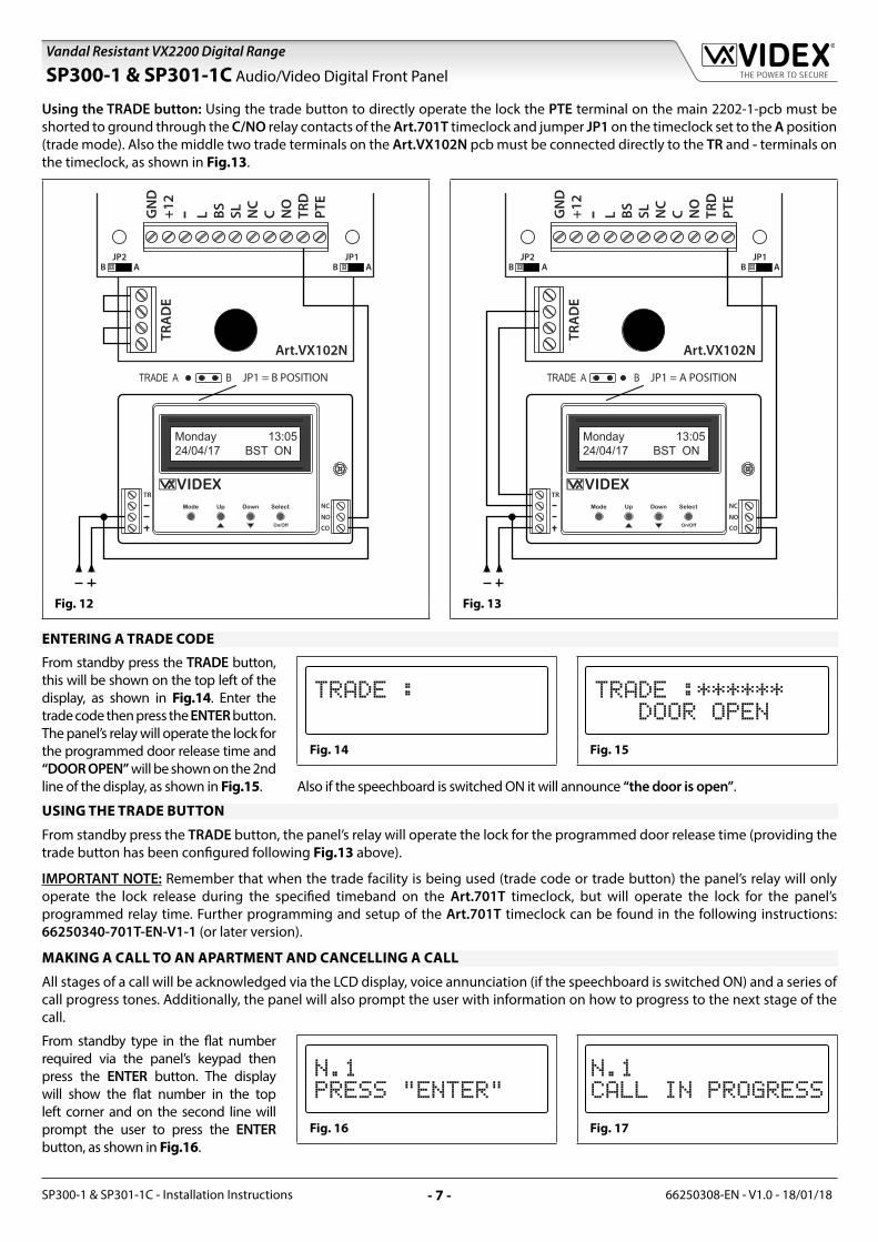
Using a TRADE code: To use this facility the TRD terminal on the main 2202-1-pcb must be shorted to ground through the C/NO relay contacts of the Art.701T timeclock and jumper JP1 on the timeclock must also be set to the B position (timeclock mode). Also the 4 trade terminals on the Art.VX102N pcb must be linked out, as shown in Fig.12.
SP300-1 & SP301-1C Audio/Video Digital Front Panel
66250308-EN - V1.0 - 18/01/18 - 7 -
Vandal Resistant VX2200 Digital Range
SP300-1 & SP301-1C - Installation Instructions
SP300-1 & SP301-1C Audio/Video Digital Front Panel
Using the TRADE button: Using the trade button to directly operate the lock the PTE terminal on the main 2202-1-pcb must be shorted to ground through the C/NO relay contacts of the Art.701T timeclock and jumper JP1 on the timeclock set to the A position (trade mode). Also the middle two trade terminals on the Art.VX102N pcb must be connected directly to the TR and - terminals on the timeclock, as shown in Fig.13.
JP1 = B POSITION JP1 = A POSITION
Fig. 12 Fig. 13
ENTERING A TRADE CODE
From standby press the TRADE button, this will be shown on the top left of the display, as shown in Fig.14. Enter the trade code then press the ENTER button. The panel’s relay will operate the lock for the programmed door release time and “DOOR OPEN” will be shown on the 2nd line of the display, as shown in Fig.15.
Fig. 14 Fig. 15
Also if the speechboard is switched ON it will announce “the door is open”.
USING THE TRADE BUTTON
From standby press the TRADE button, the panel’s relay will operate the lock for the programmed door release time (providing the trade button has been configured following Fig.13 above).
IMPORTANT NOTE: Remember that when the trade facility is being used (trade code or trade button) the panel’s relay will only operate the lock release during the specified timeband on the Art.701T timeclock, but will operate the lock for the panel’s programmed relay time. Further programming and setup of the Art.701T timeclock can be found in the following instructions: 66250340-701T-EN-V1-1 (or later version).
MAKING A CALL TO AN APARTMENT AND CANCELLING A CALL
All stages of a call will be acknowledged via the LCD display, voice annunciation (if the speechboard is switched ON) and a series of call progress tones. Additionally, the panel will also prompt the user with information on how to progress to the next stage of the call.
From standby type in the flat number required via the panel’s keypad then press the ENTER button. The display will show the flat number in the top left corner and on the second line will prompt the user to press the ENTER button, as shown in Fig.16.
Fig. 16 Fig. 17

66250308-EN - V1.0 - 18/01/18 - 8 -SP300-1 & SP301-1C - Installation Instructions
Vandal Resistant VX2200 Digital Range
If the speechboard is switched ON it will also prompt the user and announce “now press enter”. Simply press the ENTER button to make the call. The panel will make the call to the flat and the second line of the display will change to show “CALL IN PROGRESS”, as shown in Fig.17, again if the speechboard is switched ON the panel will also announce “calling number...”
If an incorrect flat number has been entered and the user wishes to cancel the call they simply press the CLEAR button, the display will revert back to the default welcome screen (see Fig.8) and if the speechboard is switched ON it will announce “call cancelled” and the call will end.
ANSWERING A CALL, RELEASING THE LOCK AND ENDING THE CALL
During a call the audio/videophone in the flat will ring. To answer the call simply pick up the handset (or if calling a hands-free device press the “answer call” button). The display will show the flat number called in the top left corner of the display and will prompt the caller to speak, this will be shown on the second line of the display as shown in Fig.18. The user that has made the call can now start a conversation with the user in the flat.
While the speech is open to the flat the user in the flat can release the lock simply by pressing the lock release button on the audio/videophone. The second line of the display will change from “SPEAK” to “DOOR OPEN” to indicate to the caller that the door is being released, as shown in Fig.19.
When the conversation between the caller and the user in the flat is finished, to end the call the user in the flat simply hangs up the handset of the audio/videophone (or if a hands-free device was called they simply press the “answer call” button again) to end the call. The second line of the display will change again, this time to “END” as shown in Fig.20, to indicate to the caller that the call is finished.
Fig. 18 Fig. 19 Fig. 20
RELEASING THE LOCK USING A PUSH TO EXIT BUTTON
A push to exit button can be connected directly to the PTE input on the digital panel and must be congifured as a “push-to-make” switch (C/NO) connected across the GND and PTE terminals, as shown in Fig.21.
The lock can be released from the panel at any time by pressing the push to exit button.
Fig. 21
SP300-1 & SP301-1C Audio/Video Digital Front Panel

66250308-EN - V1.0 - 18/01/18 - 9 -
Vandal Resistant VX2200 Digital Range
SP300-1 & SP301-1C - Installation Instructions
SP300-1 & SP301-1C Audio/Video Digital Front Panel
DIGITAL PANEL PROGRAMMING
LCD DISPLAY EXAMPLE
ENTER PRESET FACTORYCODE 0+6x1 (0111111)
CODE : ****** CODE : ******
PRESS THE ENTER BUTTON NOTE 1 ENTER MASTER CODE
(1 to 6 digits)CODE : ******NEW : ****
CODE : ******NEW : ****
PRESS THE ENTER BUTTON NOTE 1 ENTER TRADE CODE
(1 to 6 digits)TRADE C. : ******NEW : ****
TRADE C. :NEW : 1234
PRESS THE ENTER BUTTON NOTE 2 SET STANDARD OR
MAIN MODEMODE : STANDARD1 = MAIN
MODE : STANDARD1 = MAIN
PRESS THE ENTER BUTTON NOTE 3 ENTER MEMORY
LOCATION (1 to 998)MEM. LOCATION: MEM. LOCATION: 15
PRESS THE ENTER BUTTON NOTES 1, 4 ENTER FLAT NUMBER
(1 to 6 digits)FLAT :NEW : ******
FLAT :NEW : 15
PRESS THE ENTER BUTTON NOTES 1, 4 ENTER PHONE ID
ADDRESS (1 to 180)ID PHONE :NEW : ***
ID PHONE :NEW : 15
PRESS THE ENTER BUTTON NOTES 1, 4, 5 ENTER BLOCK NUMBER
(1 to 15)2206N N. :NEW : ***
2206N N. :NEW : 2
PRESS THE ENTER BUTTON NOTES 1, 4 ENTER CODE TO OPEN
DOOR (1 to 6 digits)DOOR CODE :NEW : ******
DOOR CODE :NEW : 123456
PRESS THE ENTER BUTTON
NOTE 1 OTHER USERSTO PROGRAM?
MEM. LOCATION:
PRESS THE ENTER BUTTON TWICE NOTE 1 ENTER SPEECH TIME
(1 to 255 seconds)SPEECH TIME : 120NEW : ***
SPEECH TIME : 255NEW : 60
PRESS THE ENTER BUTTON NOTE 1 ENTER DOOR TIME
(1 to 255 seconds)DOOR TIME : 3NEW : ***
DOOR TIME : 255NEW : 5
PRESS THE ENTER BUTTON NOTE 1 ENTER DEVICE NUMBER
(1 to 15)DEVICE N. : 1NEW : ***
DEVICE N. : 15NEW : 9
PRESS THE ENTER BUTTON NOTE 6 SET LANGUAGE
(0 to 5)[0]=ENG, 1=IT, 2=ESP3=POR, 4=FR, 5=GER
[0]=ENG, 1=IT, 2=ESP3=POR, 4=FR, 5=GER
PRESS THE ENTER BUTTON CONTINUED ON NEXT PAGE
YES
NO
66250308-EN - V1.0 - 18/01/18 - 10 -SP300-1 & SP301-1C - Installation Instructions
Vandal Resistant VX2200 Digital Range
SP300-1 & SP301-1C Audio/Video Digital Front Panel
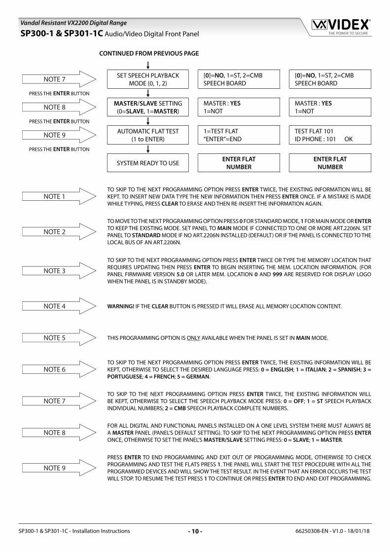
CONTINUED FROM PREVIOUS PAGE
NOTE 7 SET SPEECH PLAYBACK
MODE (0, 1, 2)[0]=NO, 1=ST, 2=CMBSPEECH BOARD
[0]=NO, 1=ST, 2=CMBSPEECH BOARD
PRESS THE ENTER BUTTON NOTE 8 MASTER/SLAVE SETTING
(0=SLAVE, 1=MASTER)MASTER : YES1=NOT
MASTER : YES1=NOT
PRESS THE ENTER BUTTON NOTE 9 AUTOMATIC FLAT TEST
(1 to ENTER)1=TEST FLAT“ENTER”=END
TEST FLAT 101ID PHONE : 101 OK
PRESS THE ENTER BUTTON SYSTEM READY TO USE
ENTER FLATNUMBER
ENTER FLATNUMBER
NOTE 1TO SKIP TO THE NEXT PROGRAMMING OPTION PRESS ENTER TWICE, THE EXISTING INFORMATION WILL BE KEPT. TO INSERT NEW DATA TYPE THE NEW INFORMATION THEN PRESS ENTER ONCE. IF A MISTAKE IS MADE WHILE TYPING, PRESS CLEAR TO ERASE AND THEN RE-INSERT THE INFORMATION AGAIN.
NOTE 2
TO MOVE TO THE NEXT PROGRAMMING OPTION PRESS 0 FOR STANDARD MODE, 1 FOR MAIN MODE OR ENTER TO KEEP THE EXISTING MODE. SET PANEL TO MAIN MODE IF CONNECTED TO ONE OR MORE ART.2206N. SET PANEL TO STANDARD MODE IF NO ART.2206N INSTALLED (DEFAULT) OR IF THE PANEL IS CONNECTED TO THE LOCAL BUS OF AN ART.2206N.
NOTE 3
TO SKIP TO THE NEXT PROGRAMMING OPTION PRESS ENTER TWICE OR TYPE THE MEMORY LOCATION THAT REQUIRES UPDATING THEN PRESS ENTER TO BEGIN INSERTING THE MEM. LOCATION INFORMATION. (FOR PANEL FIRMWARE VERSION 5.0 OR LATER MEM. LOCATION 0 AND 999 ARE RESERVED FOR DISPLAY LOGO WHEN THE PANEL IS IN STANDBY MODE).
NOTE 4 WARNING! IF THE CLEAR BUTTON IS PRESSED IT WILL ERASE ALL MEMORY LOCATION CONTENT.
NOTE 5 THIS PROGRAMMING OPTION IS ONLY AVAILABLE WHEN THE PANEL IS SET IN MAIN MODE.
NOTE 6TO SKIP TO THE NEXT PROGRAMMING OPTION PRESS ENTER TWICE, THE EXISTING INFORMATION WILL BE KEPT, OTHERWISE TO SELECT THE DESIRED LANGUAGE PRESS: 0 = ENGLISH; 1 = ITALIAN; 2 = SPANISH; 3 = PORTUGUESE; 4 = FRENCH; 5 = GERMAN.
NOTE 7TO SKIP TO THE NEXT PROGRAMMING OPTION PRESS ENTER TWICE, THE EXISTING INFORMATION WILL BE KEPT, OTHERWISE TO SELECT THE SPEECH PLAYBACK MODE PRESS: 0 = OFF; 1 = ST SPEECH PLAYBACK INDIVIDUAL NUMBERS; 2 = CMB SPEECH PLAYBACK COMPLETE NUMBERS.
NOTE 8FOR ALL DIGITAL AND FUNCTIONAL PANELS INSTALLED ON A ONE LEVEL SYSTEM THERE MUST ALWAYS BE A MASTER PANEL (PANEL’S DEFAULT SETTING). TO SKIP TO THE NEXT PROGRAMMING OPTION PRESS ENTER ONCE, OTHERWISE TO SET THE PANEL’S MASTER/SLAVE SETTING PRESS: 0 = SLAVE; 1 = MASTER.
NOTE 9
PRESS ENTER TO END PROGRAMMING AND EXIT OUT OF PROGRAMMING MODE, OTHERWISE TO CHECK PROGRAMMING AND TEST THE FLATS PRESS 1. THE PANEL WILL START THE TEST PROCEDURE WITH ALL THE PROGRAMMED DEVICES AND WILL SHOW THE TEST RESULT. IN THE EVENT THAT AN ERROR OCCURS THE TEST WILL STOP. TO RESUME THE TEST PRESS 1 TO CONTINUE OR PRESS ENTER TO END AND EXIT PROGRAMMING.

66250308-EN - V1.0 - 18/01/18 - 11 -
Vandal Resistant VX2200 Digital Range
SP300-1 & SP301-1C - Installation Instructions
ADDITIONAL PROGRAMMING NOTES
DIGITAL PANEL MODE
The SP300-1 and SP301-1C digital panel can be set to either MAIN mode or LOCAL mode (default panel mode). MAIN mode should only be used for panels that call all users and on systems that include Art.2206N bus exchange devices (one per block or one for every 180 additional apartments), otherwise the panel should be set to LOCAL mode for all other applications.
To set the panel into MAIN mode, power up with the 0 button pressed. To set the panel in LOCAL mode, power up the panel with the ENTER button pressed. The panel can also be set into LOCAL mode or MAIN mode using the 2x00PC software or by following the programming flowchart on pages 9 and 10, also refer to NOTE 2 on page 10.
Further details on the installation and setup of the Art.2206N can be found in the following technical manuals: VX2K2HDIGSYS Version 1.1 (or later) and CAB_ENUK_V1-3 (or later).
PANEL SETUP FOR 3000 SERIES AUDIO/VIDEOPHONES (DEFAULT)
To setup the digital panel to work with 3000 series audio/videophones, power up with the ENTER button pressed and wait for the display to show the panel’s firmware version “2202MSX.X S3000” on the top line (where X.X is the panel’s current firmware version), as shown in Fig.22, then release the button.
Fig. 22
PANEL SETUP FOR 900 SERIES AUDIO/VIDEOPHONES
To setup the digital panel to work with older style 900 series audio/videophones, power up with the CLEAR button pressed and wait for the display to show the panel’s firmware version “2202MSX.X S900” on the top line (where X.X is the panel’s current firmware version), as shown in Fig.23, then release the button.
Fig. 23
OTHER PROGRAMMING NOTES
During the programming of the MASTER panel all SLAVE door panels on the system will be offline (this inconvenience does not occur if the SLAVE entrances are connected via an Art.2206N bus exchange device on a separate bus).
If the programming of the MASTER panel is incorrect (e.g. the panel is programmed as a SLAVE panel when it should be programmed as a MASTER panel) an error condition will occur and is indicated with an ERROR! message on the top line of the display, as shown in Fig.24. To resolve this issue press and hold down the CODE button on the panel until the display shows CODE in the top left corner of the display (refer to Fig.9 on page 6). Proceed through the programming flowchart, on pages 9 and 10, and reset the panel as a MASTER panel, also refer to NOTE 8 on page 10.
Fig. 24
Alternatively programming a SLAVE panel as a MASTER panel in error can cause feedback issues (Larsen effect) during the conversation (only one MASTER panel should be programmed per level per block). To avoid or resolve any feedback issues that may occur it is recommended that during initial panel setup the notes on VOLUME ADJUSTMENTS on page 3 are closely followed.
Pressing the CLEAR button at any stage of the programming will clear the current data previously entered.
To enter a number to call a concierge unit (Art.2210A or Art.2210V/C if present on the system) while the concierge is in NIGHT mode, combine the “flat number” (the concierge number) with the ID PHONE address ID.1. Please also note that the ID PHONE address for all other devices (audio/videophones) on the system would start from ID PHONE address ID.2 onwards, unless the panel is in MAIN mode and an Art.2206N bus exchange device is being used in which case the programming of each user will also require the address of the Art.2206N bus exchange device (block address 1-15), also refer to the programming flowchart on pages 9 and 10.
SP300-1 & SP301-1C Audio/Video Digital Front Panel

66250308-EN - V1.0 - 18/01/18 - 12 -SP300-1 & SP301-1C - Installation Instructions
Vandal Resistant VX2200 Digital Range
SP300-1 & SP301-1C Audio/Video Digital Front Panel
GENERAL DIRECTIONS FOR INSTALLATION
CABLE SIZE GUIDE
Refer to the table below for the connections for the power supply output to the digital panel and the lock release connections.
Distance 20m
Cross Sectional Area (CSA) 0.5mm2
Ideally the power supply should be located as close to the digital panel as possible for best performance. The maximum acceptable resistance for the above cables = 3Ω or less for best possible performance.
For other VX2200 system devices refer to the following table. It is recommended that a twisted pair cable is used for the L and - databus connections and for balanced video signal connections V1 and V2 (for video systems), unless coax cable is required in which case it is recommended that an RG59(BC) coax cable is used for distances up to 200m and for distances between 200m up to 400m an RG11(BC) coax cable should be used.
VX2200 System Cable Requirements
Connections 50m 100m 200m 300m
L 0.4mm2 0.5mm2 0.75mm2 1.0mm2
- 0.4mm2 0.5mm2 0.75mm2 1.0mm2
V1 * 0.35mm2 0.5mm2 0.75mm2 1.0mm2
V2 * 0.35mm2 0.5mm2 0.75mm2 1.0mm2
+20V * 0.5mm2 0.75mm2 1.0mm2 1.5mm2
GNDV * 0.5mm2 0.75mm2 1.0mm2 1.5mm2
+12V 0.4mm2 0.75mm2 1.0mm2 1.5mm2
GND 0.4mm2 0.75mm2 1.0mm2 1.5mm2
All others ** 0.25mm2 0.35mm2 0.5mm2 0.75mm2
* - these connections are only required on video systems.
** - these are optional connections (e.g. door monitoring LED).
The maximum acceptable resistance for all the above connections (except +20V and GNDV) = 7.5 Ohms or less and the maximum acceptable resistance for the video connections +20V and GNDV = 5 Ohms or less for best possible performance. Please note that all cable sizes shown in the tables above are the minimum cable requirements. Also note that additional consideration should be given when selecting and using internal and external grade cable and should be used where appropriate.
IMPORTANT NOTE: Only bare copper (BC) cable should be used (solid or stranded is acceptable). Please be aware that when selecting a cable the following should NOT be used: Copper Coated Steel (CCS) and Copper Clad Aluminium (CCA). While these types of cable may offer a low cost solution they will have a higher resistance than pure copper cable and can affect the overall performance of the system therefore Videx DO NOT recommend these types of cable.
Further cabling information can be found the technical manual VX2200Blocks1-2 and is also provided in any acompanying installation instructions with the various audio/videophones and hands-free devices.
GENERAL INSTALLATION NOTES
• Check that all components are free from damage before installing (DO NOT proceed with installation in the event of damage).• Keep all packaging away from children.• Do not obstruct the ventilation openings or slots on any of the devices.• All connections to mains voltages must be made to the current national standards (I.E.E. wiring regulations for the UK or the
appropriate standards of your country).• Install an appropriate fused spur or isolation switch to isolate the mains where necessary and always isolate the mains before
carrying out any maintenance work on the system.• Avoid water ingress into the rear of the digital panel (or other devices) always seal the panel’s back box frame during installation
using a suitable silicon based sealant (also refer to back box installation notes on pages 14 and 15).• All intercom and access control cables must be routed separately from the mains and other high voltage cables (ideally in
separate cable ducts/trays or where this is not possible should be kept apart at a distance of no less than 30cm (12” approx.) if running in the same cable duct/tray.

66250308-EN - V1.0 - 18/01/18 - 13 -
Vandal Resistant VX2200 Digital Range
SP300-1 & SP301-1C - Installation Instructions
SP300-1 & SP301-1C Audio/Video Digital Front Panel
LOCK RELEASE WIRING AND BACK EMF PROTECTION
When fitting an electric lock release back EMF protection will be required. When fitting a DC lock release (for fail secure see Fig.25 and for fail safe see Fig.26) a 14 - 20V MOV (metal oxide varistor) must be fitted across the lock terminals as shown.
Fig. 25 Fig. 26
EARTHING THE FRONT PANEL TO THE BACK BOX
It is important to earth the digital panel’s front plate to the back box with the appropriate fixings and earth strap provided. Refer to Fig.27 and follow the steps below:
• First place the M4 flat washer followed by the M4 spring washer over the earth stud on the front plate;
• Next place the eyelet of one end of the earth strap on top of the M4 spring washer;
• Finally fit the M4 nut on top of the earth strap eyelet and tighten firmly into place;
• Repeat the steps above when fitting the other end of the earth strap to the earth stud inside the back box.
topview
VR plate
M4 washer
M4 spring washer
M4 nutearth stud
earth strap
Fig. 27
• The earth stud connection inside the back box should then be connected in the same way to the building’s earth connection.
PANEL CARE AND MAINTENANCE
As the panel is manufactured from 12 gauge brushed stainless steel it is important that the VR plate is cleaned on a regular basis to prevent dirt build up and tarnishing. A clean and soft cloth can be used with moderate warm water or non-aggressive cleansers. Additional care should be taken to follow the grain of the metal when polishing and always only polish in one direction to avoid light scratching of the plate. Also try to avoid any polish build up around the panel’s buttons which may prevent the buttons from operating correctly.
DO NOT USE ANY OF THE FOLLOWING:
• Abrasive liquids;
• Chlorine-based liquids;
• Metal cleaning products (including Sidol stainless steel cleaner as this can affect the engraving);
• Hydrochloride bleaches.

66250308-EN - V1.0 - 18/01/18 - 14 -SP300-1 & SP301-1C - Installation Instructions
Vandal Resistant VX2200 Digital Range
SP300-1 & SP301-1C Audio/Video Digital Front Panel
FLUSH BEZEL BACK BOX INSTALLATION (VRDBB140X280 AND VRDBB140X400)
135
- 140
cm
w
h
d
Fig. 28 Fig. 29 Fig. 30
Fig. 31 Fig. 32
1. The bezel box should be flushed into the wall. It is recommended that the panel is fitted at a height of approx. 135-140cm from the floor level to the centre of the speaker grill for audio digital panels and from the floor level to the centre of the camera lens for video digital panels, see Fig.28;
2. Using the bezel box and the hole dimensions: VRDBB140x280 (w=143mm x h=283mm x d=80mm); VRDBB140x400 (w=143mm x h=403mm x d=80mm), Fig.29, use appropriate tools to cut out the recommended hole size in the wall (where necessary wear the appropriate protective clothing when doing this). Allow room for the connecting cables and the 4 bezel box fixing holes;
In order to prevent water ingress we highly recommend using a silicon sealant between the wall and the bezel box, ON THE LEFT, TOP AND RIGHT SIDES ONLY AND ENSURE ALL THE CABLE ENTRY HOLES ARE SEALED. DON'T USE SILICON SEALANT ON THE BOTTOM SIDE OF THE BACK BOX (Fig.30);
3. Embed the bezel box into the wall. Feed the connecting cables through the knockouts required in the bezel box (see Fig.31) and make all necessary connections between the cable and the SP300-1 or SP301-1C digital panel following the wiring diagrams on pages 17-18. Connect the earth strap as described on page 13 (also refer to Fig.27);
4. Make any other necessary panel adjustments required (jumper settings, speech volume adjustments etc.). After the system has been tested and is working correctly place the digital panel back into the bezel box and fix it using the screwdriver provided (using the torx end) and the torx pin security screws provided (see Fig.32). Note: do not over tighten the screws more than is necessary.

66250308-EN - V1.0 - 18/01/18 - 15 -
Vandal Resistant VX2200 Digital Range
SP300-1 & SP301-1C - Installation Instructions
SP300-1 & SP301-1C Audio/Video Digital Front Panel
SURFACE BACK BOX INSTALLATION (VRDSB140X280 AND VRDSB140X400)
135
- 140
cmA A
C
D
B
E
A
Fig. 33 Fig. 34 Fig. 35
Fig. 36 Fig. 37
1. The surface box should be mounted to the wall at a height of approximately 135-140cm from the floor level to the centre of the speaker grill for audio digital panels and from the floor level to the centre of the camera lens for video digital panels, Fig.33. Place the surface box against the wall and mark the 4 fixing holes for the wall plugs and the hole for the cables , see Fig.35;
In order to prevent water ingress we highly recommend using a silicon sealant between the wall and the surface box , ON THE LEFT, TOP AND RIGHT SIDES ONLY AND ENSURE ALL THE CABLE ENTRY HOLES ARE SEALED. DON'T USE
SILICON SEALANT ON THE BOTTOM SIDE OF THE BACK BOX (Fig.34);
2. Drill the 4 fixing holes , insert the wall plugs and feed the cables through the surface box knockout required. Fix the surface box to the wall using the self-tapping masonry screws , see Fig.35, remember to allow room for the connecting cables;
3. Feed the connecting cables through the knockouts required in the bezel box (see Fig.36) and make all necessary connections between the cable and the SP300-1 or SP301-1C digital panel following the wiring diagrams on pages 17-18. Connect the earth strap as described on page 13 (also refer to Fig.27);
4. Make any other necessary panel adjustments required (jumper settings, speech volume adjustments etc.). After the system has been tested and is working correctly place the digital panel back into the surface box and fix it using the screwdriver provided (using the torx end) and the torx pin security screws provided (see Fig.37). Note: do not over tighten the screws more than is necessary.

66250308-EN - V1.0 - 18/01/18 - 16 -SP300-1 & SP301-1C - Installation Instructions
Vandal Resistant VX2200 Digital Range
SP300-1 & SP301-1C Audio/Video Digital Front Panel
ADDITIONAL BACK BOX INSTALLATION NOTES
REMOVING THE BACK BOX KNOCKOUTS
Due care should be taken when removing the knockout(s) on the base of the back box to avoid personal injury. Where necessary use the appropriate tools and wear the appropriate protective clothing (gloves, eye protection etc.) when removing the knockouts.
1. Before embeding the bezel box into the wall or mounting the surface box to the wall it is advised to first remove the knockout(s) required;
2. Take a flat-head screwdriver and use the flat end to gently ‘tap out’ and apply pressure to the knockout fixing, see Fig.38 and Fig.39;
3. Once the knockout fixing has been removed, Fig.40, push down on the knockout, see Fig.41;
4. Using a set of pliars grip the end of the knockout and ease it back and forth, Fig.42, until the other knockout fixing fatigues and the knockout breaks away from the base of the back box. If necessary file down and smooth out any rough edges with a metal file;
5. Fit a Ø20mm rubber grommet into the knockout hole, see Fig.43.
knockout �xingsknockout cover
�at-head screwdriver
‘tap out’ knockout �xing
knockout�xingremoved
Fig. 38 Fig. 39 Fig. 40
push down on the knockout
ease the knockoutback and forth toremove
�t a Ø20mmrubber grommetto the knockout hole
Fig. 41 Fig. 42 Fig. 43
EMBEDING AND FIXING THE BACK BOX TO THE WALL
The flush bezel box and surface back box need to be embeded or fixed to the wall respectively, therefore a suitable set of masonry screws and wall plugs should be used to do this. It is recommended that 4x 40mm, Ø3.5mm self-tapping masonry screws with 4x 40mm, Ø4mm nylon type wall plugs are used, see Fig.44.
Where necessary use the appropriate power tools and wear the appropriate protective clothing (gloves, eye protection etc.) when drilling the fixing holes to mount the box and cutting out the hole in the wall to embed the flush bezel box.
USING SILICON
Whenever using silicon sealant remember to wash your hands after use and always discard of any excess silicon waste responsibly. SOLID WALL
Base of back box
40mm, Ø4mm wall plug embeded into the wall
40mm, Ø3.5mm self-tapping masonry screw
Fig. 44

66250308-EN - V1.0 - 18/01/18 - 17 -
Vandal Resistant VX2200 Digital Range
SP300-1 & SP301-1C - Installation Instructions
SP300-1 & SP301-1C Audio/Video Digital Front Panel
WIRING DIAGRAMS
Connections for the SP300-1 with several audio devices (Art.3171, Art.5178 and Art.VR5178) can be seen in Fig.45. For the setup and configuration of each audio device refer to the installation instructions that acompany the device.
Fig. 45

66250308-EN - V1.0 - 18/01/18 - 18 -SP300-1 & SP301-1C - Installation Instructions
Vandal Resistant VX2200 Digital Range
SP300-1 & SP301-1C Audio/Video Digital Front Panel
Connections for the SP301-1C digital panel with several video devices (Art.6272, Art.6378, Art.6478 and Art.6778) can be seen in Fig.46. For the setup and configuration of each video device refer to the installation instructions that acompany the device.
Fig. 46

66250308-EN - V1.0 - 18/01/18 - 19 -
Vandal Resistant VX2200 Digital Range
SP300-1 & SP301-1C - Installation Instructions
SP300-1 & SP301-1C Audio/Video Digital Front Panel
NOTES

El producto lleva la marca CE que demuestra su conformidad y puede ser distribuido en todos los estados miembros de la unión europea UE.Este producto cumple con las Directivas Europeas 2014/30/EU (EMC); 2014/35/EU (LVD); 2011/65/EU (RoHS): marca CE 93/68/EEC.
Het product heeft de CE-markering om de conformiteit ervan aan te tonen en is bestemd voor distributie binnen de lidstaten van de EU zonder beperkin-gen. Dit product volgt de bepalingen van de Europese Richtlijnen 2014/30/EU (EMC); 2014/35/EU (LVD); 2011/65/EU (RoHS): CE-markering 93/68/EEG.
Le produit est marqué CE à preuve de sa conformité et peut être distribué librement à l’intérieur des pays membres de l’union européenne EU.Ce produit est conforme aux directives européennes 2014/30/EU (EMC) ; 2014/35/EU (LVD) ; 2011/65/EU (RoHS): marquage CE 93/68/EEC.
The product is CE marked demonstrating its conformity and is for distribution within all member states of the EU with no restrictions. This product follows the provisions of the European Directives 2014/30/EU (EMC); 2014/35/EU (LVD); 2011/65/EU (RoHS): CE marking 93/68/EEC.
Il prodotto è marchiato CE a dimostrazione della sua conformità e può essere distribuito liberamente all’interno dei paesi membri dell’Unione Europea UE.Questo prodotto è conforme alle direttive Europee: 2014/30/UE (EMC); 2014/35/UE (LVD); 2011/65/UE (RoHS): marcatura CE 93/68/EEC.
MANUFACTURERFABBRICANTEFABRICANTFABRICANTEFABRIKANT
VIDEX ELECTRONICS S.P.A.Via del Lavoro, 163846 Monte Giberto (FM) ItalyTel (+39) 0734 631669Fax (+39) 0734 632475www.videx.it - [email protected]
CUSTOMER SUPPORTSUPPORTO CLIENTISUPPORTS CLIENTSATENCIÓN AL CLIENTEKLANTENDIENST
VIDEX ELECTRONICS S.P.A.www.videx.it - [email protected]: +39 0734-631669Fax: +39 0734-632475
UK Customers only:VIDEX SECURITY LTDwww.videxuk.comTech Line: 0191 224 3174Fax: 0191 224 1559
Main UK office:VIDEX SECURITY LTD1 Osprey Trinity ParkTrinity WayLONDON E4 8TDPhone: (+44) 0870 300 1240Fax: (+44) 020 8523 [email protected]
Northern UK office:VIDEX SECURITY LTDUnit 4-7Chillingham Industrial EstateChapman StreetNEWCASTLE UPON TYNE - NE6 2XXTech Line: (+44) 0191 224 3174Phone: (+44) 0870 300 1240Fax: (+44) 0191 224 1559
Greece office:VIDEX HELLAS Electronics48 Filolaou Str.11633 ATHENSPhone: (+30) 210 7521028 (+30) 210 7521998 Fax: (+30) 210 [email protected]
Danish office:VIDEX DANMARKHammershusgade 15DK-2100 COPENHAGENPhone: (+45) 39 29 80 00Fax: (+45) 39 27 77 [email protected]
Benelux office:NESTOR COMPANY NVE3 laan, 93B-9800 DeinzePhone: (+32) 9 380 40 20Fax: (+32) 9 380 40 [email protected]
Dutch office:NESTOR COMPANY BVBusiness Center Twente (BCT)Grotestraat, 64NL-7622 GM [email protected]
![JP1 Version 11 - Hitachi Global [Agent] JP1/ITDM2 - Manager [Agent] Network monitoring server Windows JP1/ITDM2 - Manager JP1/ITDM2 - Manager [Network Monitor] Switch Internet Firewall](https://img.pdfslide.net/doc/110x75/5b1cd1327f8b9af2348c2109/jp1-version-11-hitachi-agent-jp1itdm2-manager-agent-network-monitoring.jpg)


![6HPHVWHU 7LPH WDEOH ZHI -XQH $ 17 · 2020. 6. 25. · 0v /lp /3 0v 1dl +& 0gp :dqj )dqj 55 6fl 1$ 0v (ol]d /rz 0v /lp 6/ 55 (/ 1$ 0v -hqqlihu :x +rph#:: 0u -hiiuh\ &kxd 0v ,y\ 1\dp](https://img.pdfslide.net/doc/110x75/5fd5d0796b0c65670c415668/6hphvwhu-7lph-wdeoh-zhi-xqh-17-2020-6-25-0v-lp-3-0v-1dl-0gp-dqj.jpg)