Embed Size (px)
Citation preview

Vanguard Applications WareMulti-Service Feature Protocols
Vanguard Integrated Services Digital Network: ISDN

Notice
©2008 Vanguard Networks.25 Forbes Boulevard Foxboro, Massachusetts 02035Phone: (508) 964-6200Fax: 508-543-0237All rights reservedPrinted in U.S.A.
Restricted Rights Notification for U.S. Government Users
The software (including firmware) addressed in this manual is provided to the U.S. Government under agreement which grants the government the minimum “restricted rights” in the software, as defined in the Federal Acquisition Regulation (FAR) or the Defense Federal Acquisition Regulation Supplement (DFARS), whichever is applicable.
If the software is procured for use by the Department of Defense, the following legend applies:
Restricted Rights LegendUse, duplication, or disclosure by the Government
is subject to restrictions as set forth in subparagraph (c)(1)(ii) of the
Rights in Technical Data and Computer Software clause at DFARS 252.227-7013.
If the software is procured for use by any U.S. Government entity other than the Department of Defense, the following notice applies:
NoticeNotwithstanding any other lease or license agreement that may pertain to, or accompany the delivery of, this computer software, the rights of the Government regarding its use, reproduction, and disclosure are as set forth in FAR 52.227-19(C).
Unpublished - rights reserved under the copyright laws of the United States.

Notice (continued)
Proprietary Material
Information and software in this document are proprietary to Vanguard Networks (or its Suppliers) and without the express prior permission of an officer, may not be copied, reproduced, disclosed to others, published, or used, in whole or in part, for any purpose other than that for which it is being made available. Use of software described in this document is subject to the terms and conditions of the Software License Agreement.
This document is for information purposes only and is subject to change without notice.
To comment on this manual, please send e-mail to [email protected]
Part No. T0103, Rev IPublication Code: TKFirst Printing: November 1998
Manual is current for Release 7.3 of Vanguard Applications Ware.

This page intentionally left blank.

Contents
v
Chapter 1.
Vanguard ISDN
Chapter 2.
ISDN Functionality and Supporting ServicesPOTS Support ............................................................................................... 2-2X.25 Functionality for BRI ........................................................................... 2-65th SCC (Software Serial Controller Channel) ............................................ 2-8Vanguard ISDN Model ................................................................................. 2-11ISDN Applications ....................................................................................... 2-14
D Packet Configuration Example ............................................................. 2-19Quick SPID Configuration ....................................................................... 2-23Link Back Up (LBU) Configuration Example ......................................... 2-25Same Port Back Up (SPBU) Configuration Example .............................. 2-27Frame Relay Same Port Back Up Example ............................................. 2-29POTS Application Examples ................................................................... 2-30Multiple PPP Configuration Example ...................................................... 2-36
Chapter 3.
Configuration and StatisticsConfiguring ISDN Ports ............................................................................... 3-2
X.25 Port Configuration ........................................................................... 3-3BRI ISDN Interface Configuration .......................................................... 3-5Booting ISDN Ports ................................................................................. 3-26ISDN BRI Voice Configuration ............................................................... 3-28ISDN BRI Voice and Data Configuration ................................................ 3-30
ISDN Statistics ............................................................................................. 3-42Other Menus Supporting ISDN .................................................................... 3-53
Chapter 4.
Cause Codes and Diagnostic Codes

Vanguard ISDN 1-1
Chapter 1Vanguard ISDN
Overview
Introduction This manual describes the Integrated Digital Services Network (ISDN) as it is offered for use on Vanguard products. At this time, only the BRI (Basic Rate Interface) version of ISDN is available for Vanguard products.
This manual is only for the software-specific information associated with the Vanguard ISDN option. Hardware installation information is contained in the various Vanguard Installation manuals.
About this Manual This option manual assumes that you are familiar with your Vanguard and its interface via the Control Terminal Port (CTP). If you need additional information about your Vanguard system, refer to the relevant Vanguard documentation.
About ISDN ISDN is an all-digital, data-communications network that allows users to access a range of separate transmission services via a single set of interface standards, providing universal end-to-end connectivity over digital lines.
Applications Ware ISDN Support
The Vanguard ISDN functionality is available in most Applications Ware licenses for Vanguard products. Certain features, such as 5th SCC, are available only for specific Vanguards. Such limitations are indicated in this manual where applicable.
ISDN Support on Vanguard Products
We offer two distinct ISDN solutions for its products. One, supporting all Vanguard products is described in this manual. The second, supporting the Vanguard 6520 and Vanguard 6560 only is described in the Vanguard 6520/6560 Integrated Services Digital Network Manual (Part Number T0103-05).
The ISDN solution described in this manual is available with any Vanguard product capable of supporting the Vanguard ISDN Daughtercard or the ISDN BRI Data Feature Card (Host Card and Daughtercard) arrangment, as it is used in Vanguard 6520 and Vanguard 6560 products.
Vanguard ISDN Functionality
The Vanguard ISDN solution provides these features and functions:
• POTS Support• X.25 functionality for BRI• 5th SCC (Software Serial Controller Channel)• ISDN applications
Chapter two covers these features and functions in detail.


ISDN Functionality and Supporting Services 2-1
Chapter 2ISDN Functionality and Supporting Services
Introduction This chapter describes the implementation of ISDN for use on all Vanguard products. In this chapter you will find:
• “POTS Support” section on page 2-2• “X.25 Functionality for BRI” section on page 2-6• “5th SCC (Software Serial Controller Channel)” section on page 2-8• “Vanguard ISDN Model” section on page 2-11• “ISDN Applications” section on page 2-14

2-2 ISDN Functionality and Supporting Services
POTS Support
POTS Support
Introduction Vanguard ISDN includes the capability to integrate both voice and data transmissions to and from Vanguard products. The voice capability is given using POTS (Plain Old Telephone System) ports on the Vanguard. For Vanguard 652 or 312 units, the POTS ports are located at the rear of the Vanguard case, and are labelled POTS1 and POTS2.
NoteCurrent Vanguard POTS over ISDN functionality is only available on certain Vanguard models. The ISDN BRI Data Feature Card for the Vanguard 6520/6560 does not provide POTS over ISDN capability.
The POTS port operates similarly to your current analog telephone line. It allows you to connect any “Standard, Good Quality” telephone devices (i.e., answering machine, modem, fax machine, or Dual Tone Multi-Frequency [DTMF] telephone) to your ISDN service using your Vanguard.
NoteDial Pulse telephone sets are not supported.
NoteISDN BRI Data Feature Card is currently not certified for connection to the Public Switched Telephone Network.
POTS Features and Functions
Vanguard POTS support includes the following features:
• Support for Off/On-Hook detection, and ringing voltage generation• Ability to initiate and receive ISDN voice calls• Support for in-band dial tones and ring-back tones from the ISDN network• Support for the ISDN signaling of the call’s progress• Logging of calls placed, received, and the duration of each
Telephone/Fax Interface Features
Vanguard POTS does not differentiate between voice, fax, or modem traffic. All traffic is handled as voice. Unless otherwise configured, all voice calls are given higher priority than data calls, and the data port is disconnected when a voice call is activated. Distinctive ringing, and pulse dialing are not supported.
If the ISDN interface is unable to originate the call, the Vanguard will not generate a dial tone. This may be caused by a SPID initialization failure, TEI problem, configuration errors, or the interface itself being down.
Tones, DTMF, and Announcements
If the phone remains off-hook after a voice call has been terminated, a five-second timeout will trigger an automatic outgoing call sequence (emulating the PSTN functionality). If the phone goes back on-hook before the timeout expires, the timer is stopped. If no DTMF information is sent in the second call, the network terminates the call automatically, and the phone remains dead until it goes back on-hook.
Network-generated tones and announcements are directed to the POTS port device. If tones are not available, the Vanguard will generate tones itself.

ISDN Functionality and Supporting Services 2-3
T0103-06, Revision I Release 7.3
POTS Support
Incoming Call Processing
If each POTS port has a unique DN (Directory Number), ringing is initiated on the POTS port with the configured DN. If both ports have a common DN, ringing is initiated on the first available POTS port, and only the device on that port can answer the call. The Vanguard then sends an alerting message to the switch.
Outgoing Call Processing
For outgoing data calls, data applications use unblock mode. For voice calls, the bearer capability uses 3.1 khz audio as the default, and “speech” is not a configurable option. The layer 1 protocol is M-Law, and it is 64K circuit mode.
Caller Line ID (CLID)
CLID service displays the name and/or number of incoming calls, on any North American Call Display Unit. This feature is available provided that your ISDN service provider supports this service.
NoteThis is generally an added cost feature that must be subscribed to from your ISDN service provider. This feature is available for North American display units only.
Figure 2-1 identifies how to connect your Vanguard device for this feature to operate.
Figure 2-1. Vanguard ISDN CLID Connections
Call Waiting Call waiting is available for voice calls using ISDN (for NI1 ISDN switches only). When this feature is enabled, a caller hears a Call Waiting tone when a second call arrives. At that point, you can either
• Hang up on the current call allowing the second call through.• Place the current call on hold by pressing the flash button or momentarily
pressing the hook switch, so that the second call is connected. (You can alternate between the two calls by pressing the flash button or pressing the switch hook.)
The Call Waiting tone is sent twice. If you do not respond to the tone, the second call is cleared.
To enable Call Waiting, you must contact the ISDN provider and ask for Additional Call Offering (ACO) and HOLD supplementary services. (If these are not available, Call Waiting cannot function.) Once these services are in place, no additional configuration is necessary; the feature is fully functional.
NoteYou cannot use Call Waiting when a fax is connected to a port. There is no way to disable the Call Waiting signal which can disrupt a fax call.
Telco ISDNNetwork
VanguardCLIDDisplayUnit

2-4 ISDN Functionality and Supporting Services
POTS Support
You can disable the Call Waiting feature for the duration of a current outgoing call. To temporarily disable Call Waiting
• Pick up the handset and dial *70.• Wait five seconds until you hear a second dial tone.• Dial the number.
After you hang up this call, Call Waiting is once again enabled.
Alternate Voice and Data
Unless otherwise configured, all voice calls are given higher priority than data calls, and the data port is disconnected when a voice call is activated (telephone is off the hook). When the voice call is disconnected, the data port is notified. It is then up to the data port to retry the connection. CVL is not supported for alternate voice and data service.
Multilink, or non-multilink data calls are not dropped for an incoming voice call request. Instead, the call is rejected.
Data Over Voice (DOV)
Data calls can be made over Voice (CSV) channels, but there are limitations on connectivity. The connection is operable only within the ISDN environment. There is no interoperability for DOV between ISDN and Analog PSTN (as this requires modem software), ISDN and non-ISDN digital networks (since it uses CSD), and ISDN connected to another ISDN over non-ISDN network (since it also uses CSD). When the switch determines the call is not end-to-end ISDN, or the call has exited the ISDN network, the DOV call is cleared.
The type of data protocol is not indicated in an ISDN call; therefore, both ends have to match. A data or voice call cannot be differentiated, but the ISDN call indicates 3.1Khz Audio or Speech.
NoteThis feature works only with third party devices that support PPP (Point-to-Point Protocol) (RFC1662) over DOV.
For an originating call, the configuration indicates that it is a DOV call. The Bearer Capability is not configurable (3.1Khz Audio will be used). When the switch determines the call is not end-to-end ISDN, or the call has exited the ISDN network, the DOV call is cleared. An automatic attempt with data bearer capability(B.C. = CVD) is tried when the first call with voice bearer capability (B.C. = 3.1K) has failed.
If the network rejects the initial SETUP request (with bearer capability set as 3.1K Audio) due to incompatible bearer capability (cause code 88) or bearer capability not available (cause code 58), the Vanguard will automatically send the SETUP request again (with bearer capability set as CSD).
For an incoming DOV call, the data port is connected to the B-Channel if the configuration indicates DOV call can be accepted (two DNs or POTS disabled). The POTS port will be connected to B-Channel if POTS is enabled and has a single DN. When the switch determines the call is not end-to-end ISDN, or the call has exited the ISDN network, the DOV call is cleared.
The actual data rate over the voice channel is 56K.
ISDN Functionality and Supporting Services 2-5
T0103-06, Revision I Release 7.3
POTS Support
If you have one common DN, and the line provisioning is set to 1B or 2B-Channels, incoming calls cannot be discriminated between voice and data. If POTS is disabled, the incoming call will go to the data connection. If both the POTS and Data port are enabled to share the same channel, the incoming call will go to the POTS.
If you have two DNs, and the line provisioning is set to 2B-Channels, the incoming call can be discriminated between voice and data. POTS disabling is not required for data connection.
Enhancements for Data Support
The following enhancements have been made to the Vanguard ISDN feature with the introduction of POTS support.
• You can now mix Permanent B and Dial B configuration within a single BRI provided that the D-Channel is configured.
• The ISDN alarms have been enhanced to track call status.• Rejected incoming calls are now logged in the call history.• The ISDN call history log can now be cleared using the “Reset Statistics”
command.• Since some Telcos have limited 64K circuits available, a B-Channel that is
configured to 64K may encounter frequent busy signals. The redial software now checks if the previous rejected call was due to NO_CIRCUIT_AVAILABLE (cause code 34). If that is the case, the line speed is automatically dropped to 56K.
POTS Specification Compliance
Vanguard POTS functionality has been designed for compatibility with the EIA/TIA-464, PBX Switching Equipment for Voiceband Applications specification.
2-6 ISDN Functionality and Supporting Services
X.25 Functionality for BRI
X.25 Functionality for BRI
Introduction This section describes functionality for BRI that is specific to X.25 connections.
If you need to have a pool of BRI channels and route calls dynamically on the BRI channels based on the Called X.25 addresses, use the Dynamic Routing and Dynamic DTE/DCE assignment.
Calling Address The system provides a user-configured Calling Addresses table.
Vanguard provides Calling Address verification of incoming calls on a per-channel basis.
The Calling Address is associated with the channel used for the outgoing call. The Calling Address is transmitted “out-of-band” in the Calling Party Number information element of the Q.931 Setup message. An ISDN call is not established unless the Calling Address matches an entry in the configured table.
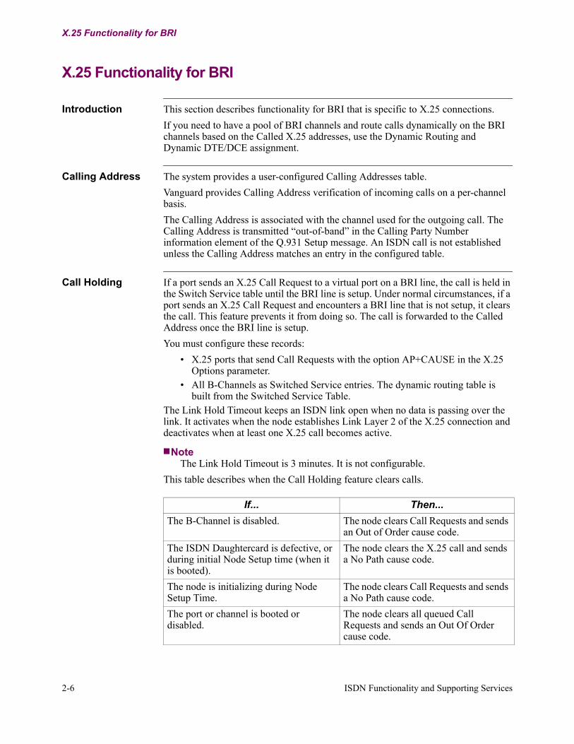
Call Holding If a port sends an X.25 Call Request to a virtual port on a BRI line, the call is held in the Switch Service table until the BRI line is setup. Under normal circumstances, if a port sends an X.25 Call Request and encounters a BRI line that is not setup, it clears the call. This feature prevents it from doing so. The call is forwarded to the Called Address once the BRI line is setup.
You must configure these records:
• X.25 ports that send Call Requests with the option AP+CAUSE in the X.25 Options parameter.
• All B-Channels as Switched Service entries. The dynamic routing table is built from the Switched Service Table.
The Link Hold Timeout keeps an ISDN link open when no data is passing over the link. It activates when the node establishes Link Layer 2 of the X.25 connection and deactivates when at least one X.25 call becomes active.
NoteThe Link Hold Timeout is 3 minutes. It is not configurable.
This table describes when the Call Holding feature clears calls.
If... Then...
The B-Channel is disabled. The node clears Call Requests and sends an Out of Order cause code.
The ISDN Daughtercard is defective, or during initial Node Setup time (when it is booted).
The node clears the X.25 call and sends a No Path cause code.
The node is initializing during Node Setup Time.
The node clears Call Requests and sends a No Path cause code.
The port or channel is booted or disabled.
The node clears all queued Call Requests and sends an Out Of Order cause code.

ISDN Functionality and Supporting Services 2-7
T0103-06, Revision I Release 7.3
X.25 Functionality for BRI
Dynamic Routing Dynamic Routing allows a pool of B-Channels to be routed “dynamically” based on the Called X.25 addresses. Here ‘dynamic’ means a call with any X.25 address can be routed to any B-Channel, provided the channel is free. A channel is dedicated to a X.25 Called Address as long as the call is in place. Once the call is disconnected, the B-Channel goes back to pool.
In addition, Dynamic Routing allows multiple calls to and from the Called Address to be routed onto the same B-Channel. All calls outgoing calls to and incoming calls from the Called Address pass across this (temporarily) dedicated link.
A node with the Dynamic Routing feature enabled reads the Call Address Extending Facility (CAEF) in an X.25 Call Request. The CAEF contains an ISDN dialing number (SPID) that is used to route the call in the following ways:
• From the CAEF, the node extracts the ISDN number (SPID) to which it makes a new ISDN call. After the B-Channel is established, it is dedicated to a specific Called Address for the duration of its call.
• The node uses the CAEF in subsequent Call Requests to determine if there is an existing B-Channel for the specified Called Address. It scans each open link to see if any current link is dedicated to the Called Address it is looking for.
The CAEF overrides the SPIDs that are configured in the ISDN Channel record. If a Call Request arrives without a CAEF, the node opens a channel with the configured SPIDs.
The CSK to enable this functionality is: QBZ662KYG9SN44Y7YD6P.
Dynamic DTE/DCE Assignment
When you use this functionality, nodes on the network are automatically assigned DTE and DCE status. At the time it establishes the ISDN connection, the node that originated the call is assigned as the status of DTE. The node that receives the call is assigned the status of DCE.
NoteThis function overrides the NEGOTIATE option in the Link Address parameter of the ISDN Channel record.
The CSK to enable this functionality is E5X2B99AA45A379VBV4K.
The ISDN Daughtercard is operational, and both B-Channels are available but dial out fails.
The node retries the same number on the same B-Channel. Once maximum retry attempts have expired, the call is cleared with an X.25 cause code.
The application (that sends the Call Request) clears the call and the ISDN call is successful.
The Call Clear from the application does not clear the ISDN link. The ISDN link disconnects only after its detects that it is not passing data and the Link Hold Timeout expires.
If... Then... (continued)

2-8 ISDN Functionality and Supporting Services
5th SCC (Software Serial Controller Channel)
5th SCC (Software Serial Controller Channel)
Introduction The MC68360 Communications Processor supports only four hardware serial communication controllers (SCC). A fifth SCC (5th SCC) has been implemented in software. This section explains how 5th SCC works and how it can be configured for your application.
Note5th SCC is only available with Vanguard 300/305, 320, 340 and 342 products.
Enable 5th SCC 5th SCC is enabled by setting the ISDN Channel Parameters parameter D-Channel Port to 4. Refer to the parameter D-Channel Port on page 3-7.
Using 5th SCC A typical application for 5th SCC is when a Vanguard 300 is connected to two remote LANs via separate switched ISDN B-Channels and when a serially attached FEP or controller is located at the site.
NoteThe 5th SCC is limited to low-speed applications and therefore can only support the ISDN D-Channel.
SCC allocation:
• 1 SCC is used for the Ethernet Port.• 1 SCC is required for the ISDN D-Channel whether it is used for data traffic
or just used for signaling.• 1 SCC is required for each ISDN B-Channel (if both B-Channels are to be
used then 2 SCCs are required).• 1 SCC is required for each serial port used.
The 5th SCC must be invoked for the ISDN D-Channel when the sum of the SCCs is 5. For example:
However, if the ISDN B-Channels are configured for permanent connection and the ISDN D-Channel is not required for data traffic, the SCC for the D-Channel is not required and can therefore, be used for a serial port.
2 ISDN B-Channels1 ISDN D-Channel1 LAN port1 serial port
= 5 SCCs

ISDN Functionality and Supporting Services 2-9
T0103-06, Revision I Release 7.3
5th SCC (Software Serial Controller Channel)
Figure 2-2 shows the logic between the MC68360 and the ports or ISDN module. The SCCs can only be assigned to one destination, either the ISDN or the serial port (but not both).
Figure 2-2. How 5th SCC Functions
Configuring 5th SCC
To configure the Vanguard 300 for 5th SCC operation:
• configure port 4 for X.25 operation.• Set the ISDN D-Channel port number to 4 instead of 1.
The B-Channels can be configured for ports 1, 2 or 3. Port 1 must be configure as a B-Channel. Refer to Figure 2-3.
Figure 2-3. 5th SCC Configuration Example
D-Channel
B1
B2
Port 1 Port 2 Port 3
Ethernet68360 Processor
Ethernet
Software SCCSCC 5
ISDN
Port 4
SMC
Control PortSCC
Port
D-Channel
B
B
Port 1 Port 2 Port 3
Ethernet68360 Processor
Ethernet
Software SCCSCC 5
ISDN
Port 4
SMC
Control PortSCC
Port

2-10 ISDN Functionality and Supporting Services
5th SCC (Software Serial Controller Channel)
Figure 2-3 shows:
• Ports 1 and 3 are configured for ISDN B-Channels.• Port 2 is configured for a serial protocol.• Port 4 is configured for the ISDN D-Channel.
Configuration Settings
This table shows how to configure Port 4 and the ISDN D-Channel parameters as shown in Figure 2-3. Only those parameters related to 5th SCC are shown. The rest of the parameters are configured as usual.
5th SCC Limitations
You need to be aware of these limitations when using 5th SCC:
• The 5th SCC is only available on port 4 and therefore the ISDN D-Channel has to be assigned to port 4. This creates a problem that there is no local CTP access. The CTP can be remotely connected using an X25 call or via Telnet. If local access is required set the front panel switch to allow CTP access via port 3 and reset the unit.
• The S/T bus cannot be shared by multiple ISDN devices when one of the devices is running the D-Channel over port 4.
• The implementation of 5th SCC causes a 30-percent load on the CPU utilization.
Parameter Setting
Port Number 4
Port Type X25
Link Address DTE
Number of SVC Channels 1
T1 Transmission Retry Timer (1/10 sec) 10
T4 Poll Timer 200
Frame Sequence Counting EXT
K Frame Window 3
X.25 Options PDN+CUD
D-Channel Port 4

ISDN Functionality and Supporting Services 2-11
T0103-06, Revision I Release 7.3
Vanguard ISDN Model
Vanguard ISDN Model
Introduction Figure 2-4 illustrates the Vanguard ISDN implementation details, and gives an overview of how to configure your Vanguard for ISDN.
Figure 2-4. ISDN Implementation Model
Vanguard 100/300/305/310/320/340
A) Configure the node.
Port 1 Port 2 Port 3
ISDN Daughtercard
D B1 B2 (Built-in on the
B) Configure the ports.
C) Configure ISDN BRI
ISDN
BRI Interface (U or S/T)
Vanguard 6400 Series
ISDN
motherboard of theVanguard 310 and 650) Port 10
Port 11 Port 12
ISDN Daughtercard #2
D B1 B2
Port 7 Port 8 Port 9
ISDN Daughtercard #1
D B1 B2
Ports 13Port 14 Port 15
ISDN Daughtercard #3
D B1 B2
(U or S/T)
Vanguard Multi-BRI Implementation
BRI I/F#1
BRI I/F#2
BRI I/F#3
Interface and mode ofoperation
(U or S/T) (U or S/T)
Vanguard 6520/6560
ISDN
ISDN BRI CARD
D B1
SLOT/PORT ASSIGNMENT
Slot 1: D = 7, B1 = 8, B2 = 9
(6560 Only)
Slot 2: D = 13, B1 = 14, B2 = 15
Slot 3: D = 19, B1 = 20, B2 = 21
Slot 3: D = 25, B1 = 26, B2 = 27
Slot 4: D = 31, B1 = 32, B2 = 33
Slot 5: D = 37, B1 = 38, B2 = 39
Slot 6: D = 43, B1 = 44, B2 = 45
Slot 7: D = 49, B1 = 50, B2 = 51
Slot 8: D = 55, B1 = 56, B2 = 57
BRI Interface #1 . . . #8(U or S/T)

2-12 ISDN Functionality and Supporting Services
Vanguard ISDN Model
Configuring Your Vanguard
There are three primary steps to configuring your Vanguard for ISDN operation.
BRI Interface Ports These tables identify how ports are allocated on Vanguard products.
Step Action Details
1 Configure the node. You must configure the node for the application you are running.
2 Configure the BRI ISDN Interface.
You need to configure each BRI ISDN Interface appropriately:
• D-Channel Port must be configured for FRI or X.25 for ISDN Permanent B, and must be X.25 for Switched B with D-Channel signaling (Q931) or D Packet data.
• B-Channel port types are PPP, X.25, or FRI. Configure them as usual. If you set the Connection Type to SIMP, the port will be Power Up Dial capable. If you set the Connection Type to DIM0, it will be Dial on Demand enabled.
NoteThere is no ISDN port (as there is for 652). ISDN is configured by assigning the appropriate channels to ports.
3 Configure the BRI ISDN Interfaces.
You must configure each BRI ISDN Interface, and the mode of operation for the application you are running, according to the parameters supplied by your ISDN Service Provider.
Port Type
VG100 VG300/305
VG320/340, 342
VG310 Series
650 Vanguard 6400 Series
D-Port 1 Either 1 or 4 1 1 7 10 13
B-Port 2 or 3 Port 1 and2 and/or 3 (if port 1 is the D-Port)or 2 or 3 (if port 4 is the D-Port)
2 and/or 3
2 or 3 8 and 9 11 and 12
14 and 15
ISDN Functionality and Supporting Services 2-13
T0103-06, Revision I Release 7.3
Vanguard ISDN Model
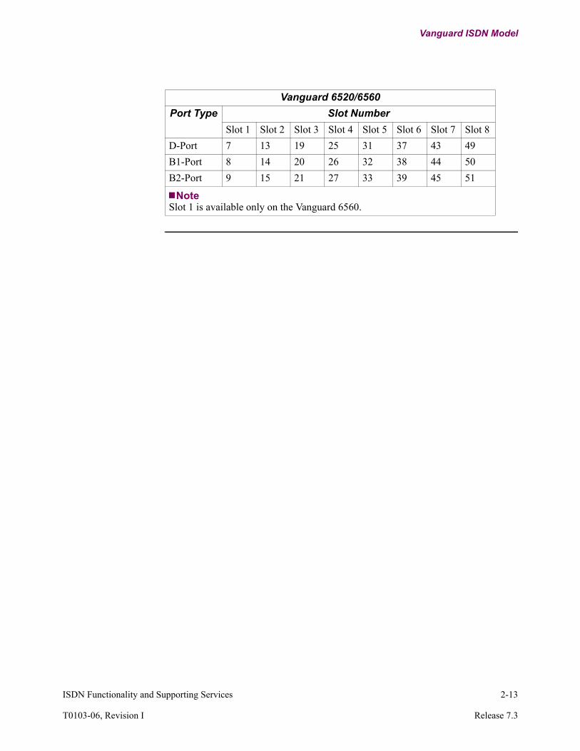
Vanguard 6520/6560
Port Type Slot Number
Slot 1 Slot 2 Slot 3 Slot 4 Slot 5 Slot 6 Slot 7 Slot 8
D-Port 7 13 19 25 31 37 43 49
B1-Port 8 14 20 26 32 38 44 50
B2-Port 9 15 21 27 33 39 45 51
NoteSlot 1 is available only on the Vanguard 6560.

2-14 ISDN Functionality and Supporting Services
ISDN Applications
ISDN Applications
Introduction The following sections outline some sample ISDN network configurations, and how to configure these examples. For detailed information on the individual parameters used in these examples, refer to Chapter 3.
NoteThe Vanguard 6400 Series and Vanguard 6520/6560 models may have different port assignments.
Auto-Configuration “Auto-configuration” allows you to plug in your Vanguard and have it configured remotely. This enables your central site system administrator to log into the control port of the Vanguard remotely, and complete the necessary configuration.
Default X.25 Port 1 Settings
Any Vanguard product, running a licensed Applications Ware image that includes the X.25 protocol, is activated with a pre-defined, factory-default configuration. This configuration sets Port 1 to X.25, and configures the first ISDN Channel. These are the X.25 port configuration parameter defaults:
Parameter Setting
Clock Source EXT
Link Address DTE
Number of SVC Channels 1
T1 Transmission Retry Timer 10
T4 Poll Timer 200
N2 Transmission Tries 3
Frame Sequence Counting EXT
K Frame Window 3
P Packet Size 256
X.25 Options PDN+CUD+NP
Number of Routing Digits in Call User Data 5
Number of SubAddress Digits in X.25 Address 0
ISDN Functionality and Supporting Services 2-15
T0103-06, Revision I Release 7.3
ISDN Applications
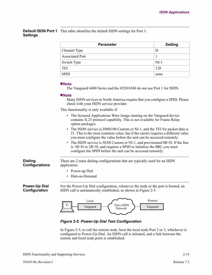
Default ISDN Port 1 Settings
This table identifies the default ISDN settings for Port 1:
NoteThe Vanguard 6400 Series and the 6520/6560 do not use Port 1 for ISDN.
NoteMany ISDN services in North America require that you configure a SPID. Please check with your ISDN service provider.
This functionality is only available if:
• The licensed Applications Ware image running on the Vanguard device contains X.25 protocol capability. This is not available for Frame Relay option packages.
• The ISDN service is DMS100 Custom or NI-1, and the TEI for packet data is 21. This is the most common value, but if the carrier requires a different value you must configure the value before the unit can be accessed remotely.
• The ISDN service is 5ESS Custom or NI-1, and provisioned 0B+D. If the line is 1B+D or 2B+D, and requires a SPID to initialize the BRI, you must configure the SPID before the unit can be accessed remotely.
Dialing Configurations
There are 2 main dialing configurations that are typically used for an ISDN application:
• Power-up Dial• Dial-on-Demand
Power-Up Dial Configuration
For the Power-Up Dial configuration, whenever the node or the port is booted, an ISDN call is automatically established, as shown in Figure 2-5.
Figure 2-5. Power-Up Dial Test Configuration
In Figure 2-5, to call the remote node, boot the local node Port 2 or 3, whichever is configured to Power-Up Dial. An ISDN call is initiated, and a link between the remote and local node ports is established.
Parameter Setting
Channel Type D
Associated Port 1
Switch Type NI-1
TEI 128
SPID none
T1 Vanguard Telco ISDNNetwork
Local Remote
Vanguard

2-16 ISDN Functionality and Supporting Services
ISDN Applications
NoteTo terminate the ISDN call when you are in Power-Up Dial mode, disable the port.
To configure the node for this application, you must:
• Configure your Port Connection Type (Port 2 or 3) as SIMPThe Port configurations are:
- Port 1 = X25 (mandatory Q931 signaling)- Port 2 = X25 or FRI or PPP; EIA type MUST be SIMP (your data port)
• Change the BRI ISDN Interface configuration to include at least one outbound number.
• BRI ISDN Interface configuration parameters are:- D-Channel Port = 1- D Packet Data = Disable (enable only if your line has D-packet provision)- Switch Type = NI-1 (or match the ISDN service provided)- First B-Channel Port = 2 (for this example)- (First) Access Type = CMD (CVL will provide virtual leased line)- (First) Line Speed (must match the rate of your line subscription)- (First) TEI = 127 (default is auto-negotiation)- (First) SPID (only required if your provider assigns one)- (First) Local DN (optional, if nothing entered, will accept all
incoming calls)- (First) Outbound Dial Number #1 (phone number that your BRI
should dial)- (First) Outbound Dial Number #2 (alternate phone number if #1 is
unavailable)
CVL for Power-Up Dial
If you set the node for the Power-up Dial configuration, set the Access Type to CVL (Circuit Mode Virtual Leased Line), and set a non-zero redial timer, this enables the call-originating node to enter into automatic redial mode when the ISDN network has dropped the outbound call. This configuration will attempt to keep the line up indefinitely, emulating a leased line.
NoteIt is recommended that you only configure one end of a link with Power-up Dial, with or without CVL, to avoid call collisions.

ISDN Functionality and Supporting Services 2-17
T0103-06, Revision I Release 7.3
ISDN Applications
Dial on Demand Configuration
This mode is used for LBU (Link Back-Up) and BoD (Bandwidth on Demand) applications.
For example:
Figure 2-6. Dial on Demand Test Configuration
Figure 2-6 depicts the configuration required when the application or protocol needs to establish a connection (on demand), such as the case where the LBU detects that the main link is down. The Vanguard initiates an ISDN call and reestablishes the link.
To configure the node for this application, you must:
• Configure your port as follows:- Port 1 = X25 (mandatory Q931 signaling)- Port 2 = X25, Connection Type MUST be DIMO, X25 option MUST have
BKUP enabled and the IDLE DISCONNECT TIMER set to a non-zero value.
NoteFRI has no support for Dial on Demand.
• Change the ISDN configuration to include an outbound number.BRI ISDN Interface configuration parameters are:
- D-Channel Port = 1- D Packet Data = Disable (enable only if your line has D-packet provision)- Switch Type = NI-1 (or match the ISDN service provided)- First B-Channel Port = 2 (for this example)- (First) Access Type = CMD (optionally, CVL)- (First) Line Speed (must match the rate of your line subscription)- (First) TEI = 127 (default is auto-negotiation)- (First) SPID (only required if your provider assigns one)- (First) Local DN (optional, if nothing entered, will accept all
incoming calls)- (First) Outbound Dial Number #1 (phone number that your BRI
should dial)• Change your routing table to have priority 0 for any address going out on the
specified port. (In this example, the remote node’s address is 100.)Routing Table:
- X25 Address = 100* (remote node’s address)- Destination = P2- Priority = 0
T1 Vanguard Telco ISDNNetwork
Local Remote
Vanguard T1

2-18 ISDN Functionality and Supporting Services
ISDN Applications
To call the remote node’s CTP:
- From the APAD prompt, type: C 10098, C- From the ATPAD prompt, type: ATD 10098, A
In each of these examples, the first call to 10098 initiates the ISDN call, and the second portion, after the comma, is the X.25 call.
Whenever a (first-time) call is made to 100XX, it initiates an ISDN dial sequence. When the ISDN connection is made, you should observe an X25 Link Up event. You can then call 100XX to reach the remote destination. When all the calls on this link have been terminated, and the idle disconnect timer has expired, the BRI ISDN connection is dropped.
NoteThe other method for terminating the ISDN call is to reboot the port, BRI ISDN Interface, or node.
A typical application will involve autocall setup on an access port to automatically retry this X.25 address.
The most common error you will encounter is that in your routing table configuration, the priority is not set to 0.
Additional Application Examples
There are additional application examples provided in the following sections. These are full configuration examples, including detailed application descriptions, of some typical application environments that you may be setting up:
• D Packet (starting on page 2-19)• Link Backup (starting on page 2-25)• Same Port Backup (starting on page 2-27)• Frame Relay Same Port Backup (starting on page 2-29)• POTS-Specific Applications (starting on page 2-30)
To simplify these examples, use default parameters whenever possible. These examples describe only the pertinent routing information and differences from a default configuration. If the parameter value is not shown here, it is assumed that the default is being used.

ISDN Functionality and Supporting Services 2-19
T0103-06, Revision I Release 7.3
ISDN Applications
D Packet Configuration Example
Introduction The example application is provided to help you understand the configuration of D-Channel Packet related ISDN parameters. Refer to the Vanguard Basics Manual (Part Number T0113) for operation of routing, mnemonic calling, SNA, and so forth.
D-Channel Application
The following section shows a typical application that would use the Vanguard 100 with the ISDN daughtercard option in its configuration.
Access to the X.25 PDN through the D-Channel is supported with this release. This can result in savings over the connection fee for a 9.6 Kbps X.25 PDN access. This mode allows economies on the cost of the infrastructure and the support for the PDN equipment. It is of interest in countries where Central Office Exchanges are ISDN-compatible and where X.25 PDN is in wide use.
In Figure 2-7, the Vanguard product on the left is connected through an X.25 connection to a PDN. Connectivity is provided to the second Vanguard through the D-Channel of an ISDN interface. In this particular example, the host is establishing a connection to an Automatic Teller Machine (ATM).
Figure 2-7. X.25 Access to PDN Using the ISDN D-Channel
For Node 1... For Node 2...
Node Record Node Record
Port Records Port Records
Station Record Station Record
Network Services• Route Selection Table
ISDN Channel
Mnemonic Table Network Services• Route Selection Table
Mnemonic Table
Host
T1
ATM
VanguardVanguard
Node 1 Node 2
PDN NetworkTelco ISDN
NetworkX.25 ISDN
P2
P3
P2
P3
Local ID: 3020 43801129Local ID: 905 507 4552
P1 P1
T2

2-20 ISDN Functionality and Supporting Services
ISDN Applications
Application Configuration
This example application shows how to configure key parameters for the following requirements:
• Configure the X.25 port for D-Channel Packet operation• Configure the LAPD parameters for D-Channel Packet operation• Configure the X.25 level 3 for ISDN D-Channel Packet and PDN operation• Ensure the ISDN management entity knows the association of the X.25 port
and D-Channel PacketThe application shown is for an SNA FEP/host connecting to an Automatic Teller Machine (ATM). The FEP connects to an HPAD (Node 1), and the HPAD connects to the TPAD (Node 2) over PDN-ISDN D-Channel Packet service. The Async terminal T1 connects to the CTP of Node 2, and the Async terminal T2 connects to the CTP of Node 1.
X.25 Call Numbering and Addressing
ISDN and PDN use different addressing schemes. The addressing scheme for internetworking is specified in the X.121 and X.122 specifications. An escape code of “0” or “9” indicates that the address that follows uses a different addressing scheme.
A PDN-attached terminal calling an ISDN (Packet service) terminal adds an escape code of “0” to the called address (ISDN type address). The network strips the “0” from the called address and adds a “0” to the calling address (calling address uses the X.121 PDN scheme) when it delivers the call request packet to the ISDN terminal. The ISDN-attached terminal (Packet service) calling a PDN terminal adds an escape code of “0” to the called address. The network strips the “0” from the called address and adds a “0” to the calling address before delivering the call request to the PDN terminal. To distinguish between different address formats within a PDN, a prefix is used.
NoteThe PDNs may have their own numbering and addressing system. Verify this with your ISDN service provider.
About This Sample Application
This X.25 call connection application example transports private X.25 addresses in the Call User Data (CUD) field. The example configuration is for Datapac (a Canadian PDN).
The Mnemonic table entries have 0 or 101 added to the destination address PDN and ISDN X.25 packet service internetworking requirements. The ISDN destination address, contained in the mnemonic table of Node 1, adds 101 to the ISDN destination address (1 is the PDN prefix, 0 is an escape code indicating a non-PDN address type, and 1 is the international dialing code for North America). The PDN destination address contained in the mnemonic table of Node 2 has 0 added to the PDN destination address. The 0 indicates a non-ISDN address type.
Node 1 to Node 2 Call
In this example, the Node 1 call request packet will have a called address of 1019055074552 and a calling address of 302043801129. The call received by Node 2 will have a called address of 19055074552 and a calling address of 0302043801129.
ISDN Functionality and Supporting Services 2-21
T0103-06, Revision I Release 7.3
ISDN Applications
Node 2 to Node 1 Call
In this example, the Node 2 call request packet will have a called address of 0302043801129 and a calling address of 19055074552. The call received by Node 1 will have a called address of 302043801129 and a calling address of 1019055074552.
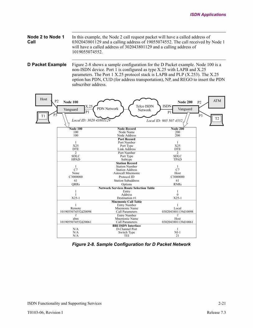
D Packet Example Figure 2-8 shows a sample configuration for the D Packet example. Node 100 is a non-ISDN device. Port 1 is configured as type X.25 with LAPB and X.25 parameters. The Port 1 X.25 protocol stack is LAPB and PLP (X.253). The X.25 option has PDN, CUD (for address transportation), NP, and REGO to insert the PDN subscriber address.
Figure 2-8. Sample Configuration for D Packet Network
Host
T1
ATM
VanguardVanguard
Node 100 Node 200
PDN NetworkTelco ISDN
NetworkX.25 ISDN
P2
P3
P2
P3Local ID: 3020 43801129 Local ID: 905 507 4552
P1 P1
T2
Node 100 Node Record Node 200100 Node Name 200100 Node Address 200
Port Record1 Port Number 1
X25 Port Type X25DTE Link Address DTE
2 Port Number 2SDLC Port Type SDLCHPAD Subtype TPAD
Station Record1 Station Number 1
C7 Station Address C7None Autocall Mnemonic Host
C3000000 Protocol ID C300000061 Station Subaddress 61
QRRs Options RNRsNetwork Services Route Selection Table
1 Entry 11 Address 0
X25-1 Destination #1 X25-1Mnemonic Call Table
1 Entry Number 1Remote Mnemonic Name Local
1019055074552d20098 Call Parameters 0302043801139d100982 Entry Number 2
abm Mnemonic Name Host1019055074552d20061 Call Parameters 0302043801139d10061
BRI ISDN InterfaceN/A D-Channel Port 1N/A Switch Type NI-1N/A TEI 21

2-22 ISDN Functionality and Supporting Services
ISDN Applications
Node 200 is an ISDN device. Port 1 is configured as type X.25. The ISDN module is configured to use PLP (X.25) on Port 1 for D-Channel Packet link. The D-Channel Packet protocol stack is X.25 on Port 1, and LAPD is added to it for layer 2, making it a D-Channel Packet port. The LAPD packet D link parameters are configured as part of the Port 1 parameters (T200 for T1 Transmission Retry Timer, N200 for N2 Transmission Tries, T203 for T4 Poll Timer, Frame Sequence Counting to EXT, and K frame Window). The X.25 parameters with PDN option have PDN, CUD (for address transportation), and NP.
NoteGenerally, SPID is not required for ISDN X.25 packet service. It may be needed for X.25 PVC operation.

ISDN Functionality and Supporting Services 2-23
T0103-06, Revision I Release 7.3
ISDN Applications
Quick SPID Configuration
Introduction This feature enables auto-configuration permits the configuration of a Telco- provided SPID, using a touch tone telephone, to allow remote access to the device from a data center over the D-packet channel.
This function is necessary if the BRI ISDN service is supported by an AT&T 5ESS (NTI or custom) switch and D and both B-Channels are supplied. This feature is not required if the BRI ISDN line is serviced by a DMS1OO switch and the configured D-Channel Terminal End-point Identifier (TEI) value is less that 63.
Configuration You perform Quick SPID configuration during the 5 second period that the TEST LED flashes after a node power-up or reset. If you do not wish to use this feature, perform no actions and normal Start-up Diagnostics occur. To configure the SPID:
Step Action Result
1 Lift up the receiver off the telephone. This is known as going Off-Hook.
The POTS1 LED flashes at a very fast rate.You now have 20 seconds to start Step 2.
2 Enter *** to enter the configuration mode.
The POTS1 LED stops flashing and remains on. This indicates the acceptance of the number entry. The TEST LED flashes at a steady rate.
NoteIf you do not enter this information within 20 seconds, or keys other than that indicated here are entered, the software continues with normal Start-up diagnostics.
3 Enter the SPID using this format:s#xxxxxxxxxxxxxxxxxxxx***where:
• s = the switch type in use.– 0 = 5ESS (with NI-1 software)– 1 = 5ESS with custom software
• x = the SPID (D-Channel or first B-Channel) provided to you by your BRI ISDN service provider.
NoteYou must start the SPID entry sequence by entering three asterisks. If the SPID provided to you is fewer than 20 characters in length, you must end the SPID format with 3 asterisks.
NoteUse the D-Channel SPID if your service provider has supplied SPIDs for D and both B-Channels, otherwise enter the SPID supplied for the first B-Channel.

2-24 ISDN Functionality and Supporting Services
ISDN Applications
Troubleshooting Once the device has been re-booted, the Status LED lights and the D LED starts to flash (Figure 2-9). Approximately 30 seconds after the correct SPID is entered, the D LED stops flashing and remains on. At this point, you have remote access to the node and the POTS port has a dial tone.
Figure 2-9. Quick SPID Troubleshooting Timeline
If the D LED does not stop flashing after approximately 120 seconds:
4 If... Then... Result
You want to terminate this procedure without modifying the original SPID record,
Place the receiver back On-Hook
a) A reset takes place a short time later.
b) Whatever entries were entered previously are discarded.
c) The original SPID record is not modified. This applies only if the node had previously been configured with a non-default SPID.
You have entered the complete SPID and want to end this procedure by saving all changes,
Replace the receiver after entering the last asterisk.
Once the SPID is accepted, Test and POTS1 leds go off and POTS2 led latch on. After 1 to 2 seconds, UUT reboots and starts the normal power up sequence again.
5 Place the receiver back On-Hook; the node will continue to boot.
Step Action Result (continued)
The Node exists the diagnostics mode and boots.
STATUS LED TEI is Learned The node is ready for remote
The D LED flashes if a SPID was entered correctly and stays on
The D LED stops flashing and stays lit if it is registered with the Telco.
If the LED continues to flash, a SPID error occurred. Re-enter the SPID or
T = 30 to 60 T = 60 seconds seconds (max)
Step Action
1 Verify that the SPID provided to you is correct (check with your ISDN service provider).
2 Verify that you have the correct switch type.
3 Repeat the configuration procedure.
ISDN Functionality and Supporting Services 2-25
T0103-06, Revision I Release 7.3
ISDN Applications
Link Back Up (LBU) Configuration Example
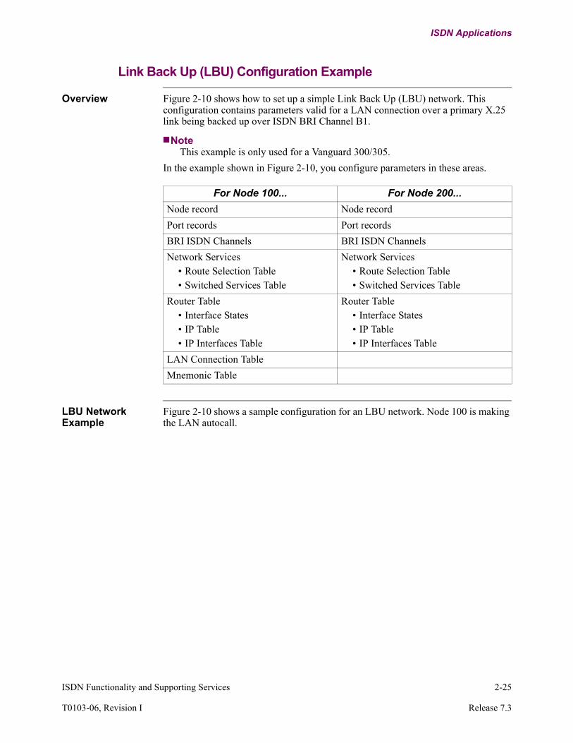
Overview Figure 2-10 shows how to set up a simple Link Back Up (LBU) network. This configuration contains parameters valid for a LAN connection over a primary X.25 link being backed up over ISDN BRI Channel B1.
NoteThis example is only used for a Vanguard 300/305.
In the example shown in Figure 2-10, you configure parameters in these areas.
LBU Network Example
Figure 2-10 shows a sample configuration for an LBU network. Node 100 is making the LAN autocall.
For Node 100... For Node 200...
Node record Node record
Port records Port records
BRI ISDN Channels BRI ISDN Channels
Network Services• Route Selection Table• Switched Services Table
Network Services• Route Selection Table• Switched Services Table
Router Table• Interface States• IP Table• IP Interfaces Table
Router Table• Interface States• IP Table• IP Interfaces Table
LAN Connection Table
Mnemonic Table

2-26 ISDN Functionality and Supporting Services
ISDN Applications
Figure 2-10. Sample Configuration for LBU Network
Vanguard Vanguard
ISDN
PDNX.25
PC
Node 100 Node 200
PCPort 3 Port 3Port 1
Port 2ISDN
Eth
B-Channel
Port 1
Port 2B-Channel
Node 100 Node Record Node 200100 Node Name 200100 Node Address 200
High+med+conn Alarm Selection High+med+connPort Record
1 Port Number 1X25 Port Type X25DTE Link Address DTE
2 Port Number 2X25 Port Type X25
Negotiate Link Address DTE3 Port Number 3
X25 Port Type X25Negotiate Link Address Negotiate
5 Port Number 5ETH Port Type ETH
BRI ISDN Interface1 D-Channel Port 1
(service provided) Switch Type (service provided)2 First B-Channel Port SPID 2
(service provided) (First) SPID (service provided)(service provided) (First) Local Subscriber Directory Number (service provided)
Network Services Route Selection Table1 Entry 1
200 Address 100X25-3 Destination #1 X25-3
1 Priority 1N/A Entry 2N/A Address 20094N/A Destination #1 LCONN/A Priority 0
Network Services Switched Services Table(choice) Destination Name LBU PortX25-2 Monitored Port X25-2Port 3 Backup or Switched Services Port Port 3Fail Activation Mode Fail
(Node 200’s Phone #) Dial Sequence (Node 100’s Phone #)IMM Deactivation Mode IMM300 Link Hold Time 300
30 (Can’t be 0) Redial Timer 30 (Can’t be 0)Router Table Interface States
Enabled Interface 1 EnabledEnabled Interface 5 Enabled
Router IP Table“;” Parameters “;”
Router Table IP Interfaces Table1 Entry 11 Interface 1
Determined by network (219.1.80.1) IP Address Determined by network (219.1.80.1)Determined by network (255.255.255.0) Address Mask Determined by network (255.255.255.0)
2 Entry 25 Interface 5
Determined by network (219.1.81.1) IP Address Determined by network (219.1.81.1)Determined by network (255.255.255.0) Address Mask Determined by network (255.255.255.0)
Mnemonic Table1 Entry N/A
Callan Mnemonic Name N/A20094 Call Parameters N/A
LAN Connection TableRout Forwarder Type N/A
5 Router Interface N/ACallan Autocall Mnemonic N/A
ISDN Network

ISDN Functionality and Supporting Services 2-27
T0103-06, Revision I Release 7.3
ISDN Applications
Same Port Back Up (SPBU) Configuration Example
Overview Figure 2-11 shows how to set up a simple Same Port Back Up (SPBU) network. This configuration contains parameters valid for a LAN connection over a primary X.25 link being backed up over ISDN BRI Channel B1.
NoteThis example is only used for a Vanguard 300/305. SPBU is also available for Vanguard 100, and the configuration is similar to what is given here, but the user port is serial, not Ethernet. The Vanguard 6400 Series does not support Same Port Back-up.
In the example shown in Figure 2-11, you configure parameters in the following areas.
SPBU Network Example
Figure 2-11 shows a sample configuration for an SPBU network. Node 100 is making the LAN autocall.
For Node 100... For Node 200...
Node record Node record
Port records Port records
BRI ISDN Channels BRI ISDN Channels
Network Services• Route Selection Table
Network Services• Route Selection Table
Router Table• Interface States• IP Table• IP Interfaces Table
Router Table• Interface States• IP Table• IP Interfaces Table
LAN Connection Table
Mnemonic Table

2-28 ISDN Functionality and Supporting Services
ISDN Applications
Figure 2-11. Sample Configuration for SPBU Network
Vanguard Vanguard
ISDN Network
ISDN
PDNX.25
PC
Node 100 Node 200
PC
300** 300**
Port 2 Port 2Port 1
Port 2ISDN
Eth
B-Channel
Port 1
Port 2B-Channel
Port 3 forSerial Applications
D-ChannelD-Channel
Node 100 Node Record Node 200100 Node Name 200100 Node Address 200
High+med+conn Alarm Selection High+med+connPort Record
1 Port Number 1X25 Port Type X25DTE Link Address DTE
2 Port: Number 2X25 Port Type X25
Negotiate Link Address DTE5 Port Number 5
ETH Port Type ETHBRI ISDN Channels
1 D-Channel Port 1(service provided) Switch Type (ISDN service provided)
2 First B-Channel Port 2CMD (First) Access Type CMDEnable (First) Same Port Backup Enable
Call+Time First) Same Port Backup Option Call30 (First) Same Port Backup Timeout 30127 (First) TEI 127
(service provided) (First) SPID (ISDN service provided)(service provided) (First) Outbound Dial Number #1 (ISDN service provided)
Router Table Interface StatesEnabled Interface 1 EnabledEnabled Interface 5 Enabled
Router IP TableAll values are default, but you must enter and save the values
with a “;”
Parameters All values are default, but you must enter and save the values
with a “;”Router Table IP Interfaces Table
1 Entry 11 Interface 1
Determined by network IP Address Determined by network Determined by network Address Mask Determined by network
2 Entry 25 Interface 5
Determined by network IP Address Determined by network Determined by network Address Mask Determined by network
Network Services Route Selection Table1 Entry 1
200 Address 1001 Priority 1
Mnemonic Table1 Entry N/A
Callan Mnemonic Name N/A20094 Call Parameters N/A
LAN Connection TableRout Forwarder Type N/A
5 Router Interface N/ACallan Autocall Mnemonic N/A
** Note: For a Vanguard 100, Port 3 is the user port. For a Vanguard 300, Port 3 is an additional serial user port.

ISDN Functionality and Supporting Services 2-29
T0103-06, Revision I Release 7.3
ISDN Applications
Frame Relay Same Port Back Up Example
Overview This feature provides ISDN dial-backup service for Frame Relay DTE ports. With this feature, if a Frame Relay network PVC is inactive, the specified FRI port establishes an alternate FR connection over an ISDN service. This feature is only supported by Vanguard 100, Vanguard 300/305, Vanguard 320, 340 and 342.
Inactive Port An alternate Frame Relay connection is established when the PVC is inactive or unusable for the following reasons:
• Control protocol error condition, such as:- In-channel signalling link (DLCI 0, DLCI 1023) reliability errors- Signalling link protocol errors- Internal network problems
• The network reports that a link’s PVCs are inactive.• Priority Station Connection Loss (a DLCI failure [network PVC] failure is
detected).
Configuring Same Port Back Up
To implement Frame Relay Same Port Back Up, you need to configure parameters in two records:
• Frame Relay Port Record- Priority Station: specifies a station whose PVC status has priority over all
other stations when FRI same port backup is enabled. When the network reports this DLCI inactive, an alternate connection over a backup link is attempted. To specify no station, select 0 (zero).
• BRI ISDN Configuration Records- Channel Port: specifies the port to be used for the same port backup- Same Port Backup: when set to ENABLE, this port is configured for Same
Port Backup- Same Port Backup Option: specifies the switchback criteria for the backup
ISDN line- Same Port Backup Timeout: specifies the time, in minutes, when the ISDN
backup line switches back- Outbound Dial Number: gives the phone number to dial when establishing
an ISDN outbound call- Call Retry Interval: defines the time, in seconds, between ISDN dial
attempts- Number of Call Retries: specifies the number of times the ISDN will
attempt the call at the Call Retry Interval

2-30 ISDN Functionality and Supporting Services
ISDN Applications
POTS Application Examples
Overview The purpose of these example applications is to understand the configuration of voice-related ISDN parameters. For information about operation or configuration of routing, mnemonic calling, SNA, etc., refer to the Vanguard Applications Ware Documentation Set.
The following sections show how to set the key parameters for application environments using:
• Voice only• Shared and dedicated data/voice• Data over voice
Voice Specific Application
This setup assumes that each B-Channel is on a separate terminal (with its own SPID and DN) using the DMS100 switch. The phone and fax machines each connect to a separate POTS port, and each has its own phone number. The Packet-D connection is used for other data connections (for example, POS and Security Alarms). See Figure 2-12.
Figure 2-12. Voice-Specific Application Example
652 orISDN PSTN
Fax
Lottery Terminal
Touch Tone Phone
POTS1
POTS2
P1
5074823
5074388VG312
BRI
ISDN Functionality and Supporting Services 2-31
T0103-06, Revision I Release 7.3
ISDN Applications
Application Configuration
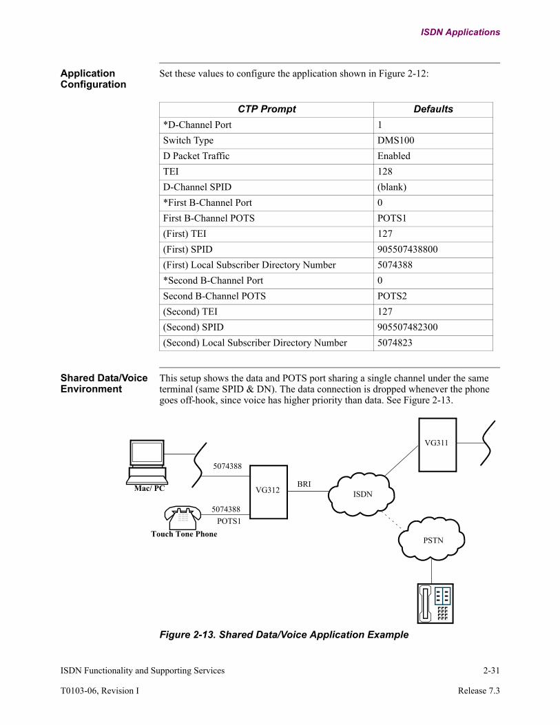
Set these values to configure the application shown in Figure 2-12:
Shared Data/Voice Environment
This setup shows the data and POTS port sharing a single channel under the same terminal (same SPID & DN). The data connection is dropped whenever the phone goes off-hook, since voice has higher priority than data. See Figure 2-13.
Figure 2-13. Shared Data/Voice Application Example
CTP Prompt Defaults
*D-Channel Port 1
Switch Type DMS100
D Packet Traffic Enabled
TEI 128
D-Channel SPID (blank)
*First B-Channel Port 0
First B-Channel POTS POTS1
(First) TEI 127
(First) SPID 905507438800
(First) Local Subscriber Directory Number 5074388
*Second B-Channel Port 0
Second B-Channel POTS POTS2
(Second) TEI 127
(Second) SPID 905507482300
(Second) Local Subscriber Directory Number 5074823
Mac/ PCISDN
PSTNTouch Tone Phone
POTS1
5074388
5074388
VG312
VG311
BRI

2-32 ISDN Functionality and Supporting Services
ISDN Applications
Application Configuration
Set these values to configure the application shown in Figure 2-13:
CTP Prompt Defaults
*D-Channel Port 1
Switch Type NI-1
D Packet Traffic Disable
*First B-Channel Port 2
First B-Channel POTS POTS1
(First) Access Type CMD
(First) Line Speed 56K
(First) TEI 127
(First) SPID 905507438800
(First) Local Subscriber Directory Number 5074388
(First) Sub-Address (blank)
(First) Call Permission OUT+INC
(First) Channel Selection Preferred
(First) Outbound Dial Number #1 95074240
(First) Outbound Dial Number #2 (blank)
(First) Dial Retry Interval 30
(First) Number of Call Retries 5
*Second B-Channel Port 0
Second B-Channel POTS None
ISDN Functionality and Supporting Services 2-33
T0103-06, Revision I Release 7.3
ISDN Applications
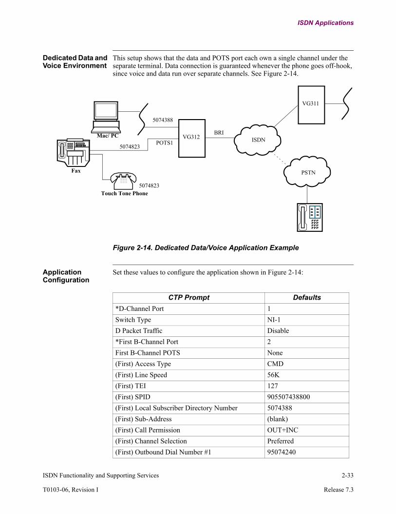
Dedicated Data and Voice Environment
This setup shows that the data and POTS port each own a single channel under the separate terminal. Data connection is guaranteed whenever the phone goes off-hook, since voice and data run over separate channels. See Figure 2-14.
Figure 2-14. Dedicated Data/Voice Application Example
Application Configuration
Set these values to configure the application shown in Figure 2-14:
Mac/ PCISDN
PSTN
5074388
VG312
VG311
Fax
Touch Tone Phone
POTS1
5074823
5074823
BRI
CTP Prompt Defaults
*D-Channel Port 1
Switch Type NI-1
D Packet Traffic Disable
*First B-Channel Port 2
First B-Channel POTS None
(First) Access Type CMD
(First) Line Speed 56K
(First) TEI 127
(First) SPID 905507438800
(First) Local Subscriber Directory Number 5074388
(First) Sub-Address (blank)
(First) Call Permission OUT+INC
(First) Channel Selection Preferred
(First) Outbound Dial Number #1 95074240

2-34 ISDN Functionality and Supporting Services
ISDN Applications
Data Over Voice Application
This setup shows using the cheaper tariffs circuit (3.1K Audio) to establish data connections. Note that the configuration of the units on both ends should match. See Figure 2-15.
Figure 2-15. Data Over Voice Application Example
Application Configuration
Set these values to configure the application shown in Figure 2-15:
(First) Outbound Dial Number #2 (blank)
(First) Dial Retry Interval 30
(First) Number of Call Retries 5
*Second B-Channel Port 0
Second B-Channel POTS POTS1
(Second) TEI 127
(Second) SPID 905507482300
(Second) Local Subscriber Directory Number 5074823
CTP Prompt (continued) Defaults
Mac/PC
ISDN5074388
VG312 VG312
Mac/PC
BRI BRI
CTP Prompt Defaults
*D-Channel Port 1
Switch Type NI-1
D Packet Traffic Disable
*First B-Channel Port 2
First B-Channel POTS None
(First) Access Type DOV
(First) TEI 127
(First) SPID 905507438800
(First) Local Subscriber Directory Number 5074388
(First) Sub-Address (blank)
(First) Call Permission OUT+INC
(First) Channel Selection Preferred
(First) Outbound Dial Number #1 95074240

ISDN Functionality and Supporting Services 2-35
T0103-06, Revision I Release 7.3
ISDN Applications
(First) Outbound Dial Number #2 (blank)
(First) Dial Retry Interval 30
(First) Number of Call Retries 5
*Second B-Channel Port 0
Second B-Channel POTS None
CTP Prompt (continued) Defaults

Multiple PPP Configuration Example
Introduction Figure 2-16 and Figure 2-17 illustrate how to configure a Multiple PPP connection via European ISDN BRI (ETSI) with the 3400 Series devices.
Figure 2-16. Multiple PPP Configuration Example, Node 3480
Node 3480
56.1.1.0/24
Node 3460
IPCP options: ADDR + VJ
Port 105*Port Type: PPP*Stacking Support: NONE*Line Interface: ISDN*PPP Operation: MultilinkAlternate CHAP Name Control: Disabled *Maximum Number of Config Request Attempts: 0MLP Multiclass: Disabled Initial Bandwidth: 64000Debug: NONE
P 7 (BRI) P 7 (BRI)
INT#5INT#51
Port 2 Port 1
5552000
LCON 1 Connected to MLPPP1 LCON 1 Connected to MLPPP1Local IP Addr: 56.1.1.2Remote IP Addr: 56.1.1.1
55520005551000
MLPPPISDN
Network
PVC Setup Table*Source: LCON-1*Destination: MLPPP-1
LAN Connection Table*Lan Forwarder Type: ROUTLan Connection Type: PT_TO_PT*Router Interface Number: 51
Router Interface States*Interface State : Enabled
IP Interface ConfigurationInterface Number: 51IP Address : 56.1.1.1IP Address Mask: 255.255.255.0
PPP/MLP Authentication ParameterPPP Node Name: 3480_3460Authentication Protocol: CHAP_CPAP Password: vanguard
PPP/MLP ProfilesAccount Name: 3460_3480Authentication Protocol: CHAP_CCHAP Secret: vanguardAlternate CHAP Client Secret: (blank)Network Protocols: IPIPCP options: ADDR+VJTCP header compression max slot index: 15Local IP Address: 56.1.1.1Remote IP Address: 56.1.1.2Encapsulation: RFC1490Compression Control Protocol: NONEDial Number #1: 5552000Dial Number #2: (blank)*Dedicated Links: 105Maximum Number of associated Switched Links: 0Prioritization: DisabledTx CIR Kbit/sec rate (when non-zero): 0Minimum Segment Size: 32
BRI ISDN Interface*D Channel Port: 7*Format: DATA*Switch Type: ETSILine Termination: 100-OhmD Packet Traffic: DISABLE*First B Channel Port: 101(First) Access Type: CMD(First) Same Port Backup: DISABLE(First) Line Speed: 64K(First) TEI: 127(First) Local Subscriber Directory Number: 5551000(First) Sub-Address: (blank)(First) Call Permission: OUT+INC(First) Channel Selection: PREFERRED(First) Outbound Dial Number #1: (blank)(First) Outbound Dial Number #2: (blank)(First) Dial Retry Interval: 30(First) Number of Call Retries: 5

ISDN Functionality and Supporting Services 2-37
T0103-06, Revision I Release 7.3
ISDN Applications
Figure 2-17. Multiple PPP Configuration Example, Node 3460
Node 3480
56.1.1.0/24
Node 3460
IPCP options: ADDR + VJ
P 7 (BRI) P 7 (BRI)
INT#5INT#51
Port 2 Port 1
5552000
LCON 1 Connected to MLPPP1 LCON 1 Connected to MLPPP1Local IP Addr: 56.1.1.2Remote IP Addr: 56.1.1.1
55520005551000
MLPPPISDN
Network
Port 105*Port Type: PPP*Stacking Support: NONE*Line Interface: ISDN*PPP Operation: MultilinkAlternate CHAP Name Control: Disabled*Maximum Number of Config Request Attempts: 0MLP Multiclass: DisabledInitial Bandwidth: 64000Debug: NONE
PVC Setup Table*Source: LCON-1*Destination: MLPPP-1
NUI/Password TableAccount Name: 3480_3460Password: vanguardPAD Prompt Number: 0
PPP/MLP Authentication ParameterPPP Node Name: 3460_3480Authentication Protocol: CHAP_SPAP Password: vanguard
PPP/MLP ProfilesAccount Name: 3480_3460Authentication Protocol: CHAP_SCHAP Secret: vanguardNetwork Protocols: IPIPCP options: ADDR+VJTCP header compression max slot index: 15Local IP Address: 0.0.0.0Remote IP Address: 0.0.0.0Encapsulation: RFC1490Compression Control Protocol: NONEDial Number #1: (blank)*Dedicated Links: 105Maximum Number of associated Switched Links: 0Prioritization: DisabledTx CIR Kbit/sec rate (when non-zero): 0Minimum Segment Size: 32IPCP Debug: NONEIPHC Debug: NONE
BRI ISDN Interface*D Channel Port: 7*Format: DATA*Switch Type: ETSILine Termination: 100-OhmD Packet Traffic: DISABLE*First B Channel Port: 101(First) Access Type: CMD(First) Same Port Backup: DISABLE(First) Line Speed: 64K(First) TEI: 127(First) Local Subscriber Directory Number: 5552000(First) Sub-Address: (blank)(First) Call Permission: INC(First) Channel Selection: PREFERRED(First) Outbound Dial Number #1: (blank)(First) Outbound Dial Number #2: (blank)(First) Dial Retry Interval: 30(First) Number of Call Retries: 5
LAN Connection Table*Lan Forwarder Type: ROUTLan Connection Type: PT_TO_PT*Router Interface Number: 5
Router Interface States*Interface State : Enabled
IP Parameters*Maximum Number of IP Interfaces: 36Access Control: DisabledRIP Enable: DisabledDefault Gateway: 0.0.0.4
IP Interface ConfigurationInterface Number: 5IP Address : 0.0.0.4IP Address Mask: 255.255.255.0


Configuration and Statistics 3-1
Chapter 3Configuration and Statistics
Introduction This chapter describes how to configure ISDN software on Vanguard products that support the ISDN Daughtercard or the ISDN BRI Data Feature Card options.
This chapter includes this configuration information:
• “X.25 Port Configuration” section on page 3-3• “BRI ISDN Interface Configuration” section on page 3-5• “Booting ISDN Ports” section on page 3-26
NoteConfiguration involves changing many different Vanguard ISDN parameters. In many cases, you will have to perform a Port boot for these changes to take effect. When a different boot type is required, it will be identified in the parameter description.

3-2 Configuration and Statistics
Configuring ISDN Ports
Configuring ISDN Ports
Introduction This section describes how to configure the ISDN software available from the Multi-Service Applications Ware software license.
Configuration Once the card is installed and the node rebooted, Vanguard products automatically recognize the ISDN daughtercard or ISDN BRI Data Feature Card. The CTP Configure menu will also show the BRI ISDN option, with a typical example shown in Figure 3-1.
Figure 3-1. Configure Menu
This section describes configuration of these functions:
• “X.25 Port Configuration” section on page 3-3• “BRI ISDN Interface Configuration” section on page 3-5
On completion of configuration activities, you will have to perform a Port Boot. Refer to “Booting ISDN Ports” section on page 3-26, for additional information.
Node: Menu: Configure Path: (Main.6)
Node (reserved)Port (reserved)Configure Network Services (reserved)Inbound Call Translation Table (reserved)Outbound Call Translation Table (reserved)Calling Addr Translation Table (reserved)Software Key Table (reserved)TCP (reserved)NUI/Password Table (reserved)
(reserved) (reserved)(reserved) (reserved)(reserved) Configure SNMP(reserved) (reserved) Configure BRI ISDN Interface(reserved) (reserved) (reserved)
#Enter Selection:
Configuration and Statistics 3-3
T0103-06, Revision I Release 7.3
Configuring ISDN Ports
X.25 Port Configuration
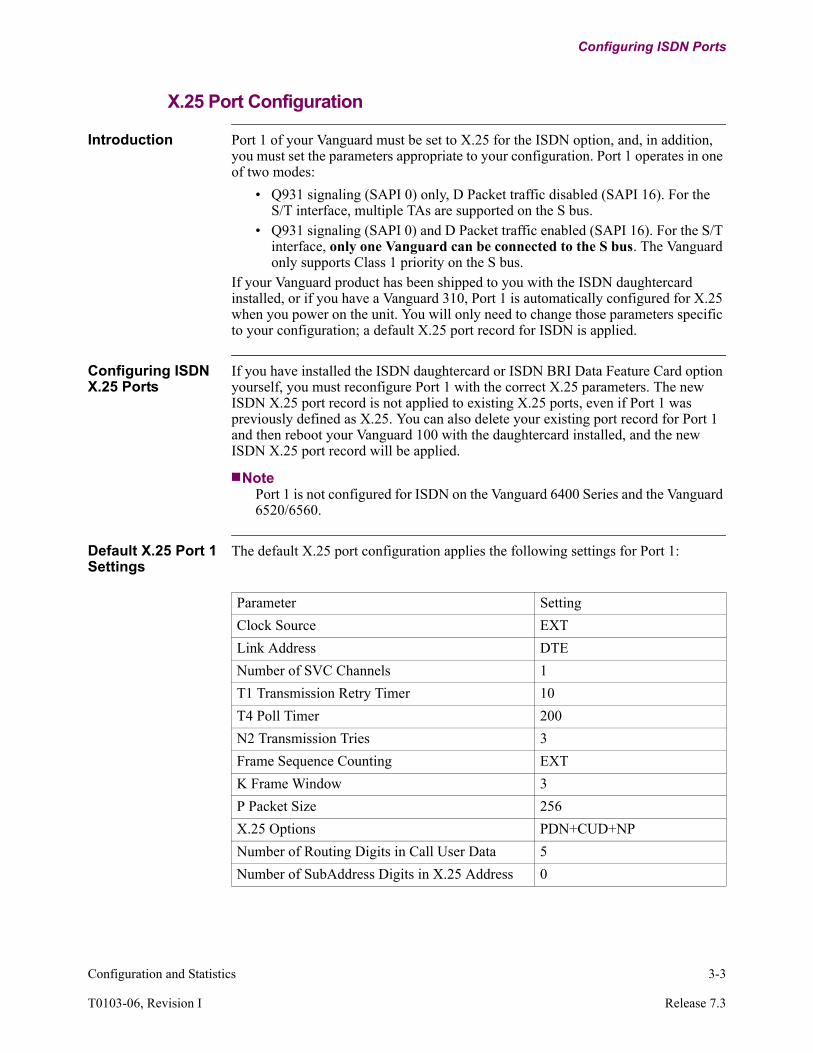
Introduction Port 1 of your Vanguard must be set to X.25 for the ISDN option, and, in addition, you must set the parameters appropriate to your configuration. Port 1 operates in one of two modes:
• Q931 signaling (SAPI 0) only, D Packet traffic disabled (SAPI 16). For the S/T interface, multiple TAs are supported on the S bus.
• Q931 signaling (SAPI 0) and D Packet traffic enabled (SAPI 16). For the S/T interface, only one Vanguard can be connected to the S bus. The Vanguard only supports Class 1 priority on the S bus.
If your Vanguard product has been shipped to you with the ISDN daughtercard installed, or if you have a Vanguard 310, Port 1 is automatically configured for X.25 when you power on the unit. You will only need to change those parameters specific to your configuration; a default X.25 port record for ISDN is applied.
Configuring ISDN X.25 Ports
If you have installed the ISDN daughtercard or ISDN BRI Data Feature Card option yourself, you must reconfigure Port 1 with the correct X.25 parameters. The new ISDN X.25 port record is not applied to existing X.25 ports, even if Port 1 was previously defined as X.25. You can also delete your existing port record for Port 1 and then reboot your Vanguard 100 with the daughtercard installed, and the new ISDN X.25 port record will be applied.
NotePort 1 is not configured for ISDN on the Vanguard 6400 Series and the Vanguard 6520/6560.
Default X.25 Port 1 Settings
The default X.25 port configuration applies the following settings for Port 1:
Parameter Setting
Clock Source EXT
Link Address DTE
Number of SVC Channels 1
T1 Transmission Retry Timer 10
T4 Poll Timer 200
N2 Transmission Tries 3
Frame Sequence Counting EXT
K Frame Window 3
P Packet Size 256
X.25 Options PDN+CUD+NP
Number of Routing Digits in Call User Data 5
Number of SubAddress Digits in X.25 Address 0

3-4 Configuration and Statistics
Configuring ISDN Ports
X.25 (LAPB) vs. ISDN X.25 (LAPD) Parameters
Although Port 1 is still configured for X.25, the parameters used for ISDN X.25 differ from the standard X.25 parameters in that X.25 uses LAPB, and ISDN X.25 uses LAPD.
Mapping ISDN-X.25 to X.25 Parameter Settings
ISDN X.25 (LAPD) parameters have the following mapping to the usual Vanguard X.25 parameter settings (D Packet SAPI 16):
X.25 Port Configuration Screen Example
A portion of the X.25 Port Configuration screen is shown in Figure 3-2.
Figure 3-2. Example of X.25 Port Configuration Screen
ISDN X.25 (LAPD)
Parameter
Type Vanguard Standard X.25 Configuration
(LAPB) Equivalent
Default Range
T200 Configurable T1 1 sec 0.1 - 25.4 sec
T201 Not supported
T202 Fixed 2 sec None
T203 Configurable T4 20 sec 1 - 25.5 sec
T204 Fixed 2 sec
N200 Configurable N2 3 1 - 20
N201 Configurable Pkt Size 256 128 or 256
N202 Fixed 2
K Configurable K 3 1 - 15
N204 Fixed 3
Port Configuration
Port Number: 1/[1] *Port Type: X25/[1] Connection Type: SIMP/[1] Port Control: NONE/[1] Clock Source: EXT/[1] Clock Speed: 9600/[1] Link Address: DTE/...

Configuration and Statistics 3-5
T0103-06, Revision I Release 7.3
Configuring ISDN Ports
BRI ISDN Interface Configuration
Accessing the BRI ISDN Configuration Menu
Complete this procedure to access the BRI ISDN Configuration menu.
Step Do This... Result
1 Select Configure from the CTP Main menu.
The Configure menu is displayed.
2 Select Configure BRI ISDN Interface from the Configure menu.
The screen for selecting the BRI ISDN interface choices appears.
3 Select BRI ISDN Interfaces from the choices.
The screen prompts you for an Entry Number that is used for CMEM identification.
4 Provide the Entry Number for the interface you wish to configure.
The next parameter prompt appears. A typical BRI ISDN Interface configuration screen parameters is shown in Figure 3-3.

3-6 Configuration and Statistics
Configuring ISDN Ports
The BRI ISDN configuration menu is entered by selecting Configure BRI ISDN Interface in the Configure menu, and then selecting BRI ISDN Interfaces. The screen prompts for an Entry Number that is used for CMEM identification. A typical BRI ISDN Interface configuration screen is shown in Figure 3-3.
Figure 3-3. Example of BRI ISDN Interface Configuration Screen
BRI ISDN Interface Configuration
Entry Number: 1/[1] *D-Channel Port: 1/[1] Switch Type: NI-1/[1] D Packet Traffic: ENABLE/[1] TEI: 21/[1] D-Channel SPID: (blank)/[1] *First B-Channel Port: 2/[1] *First B-Channel POTS: POTS1/[1] (First) Access Type: CMD/[1] (First) Same Port Backup: DISABLE/[1] (First) Same Port Backup Option: TIMEOUT/[1] (First) Same Port Backup Timeout: 0/[1] (First) Line Speed: 56K/[1] (First) TEI: 127/[1] (First) SPID: (blank)/[1] (First) Local Subscriber Directory Number: (blank)/[1] (First) Sub-Address: (blank)/[1] (First) Call Permission: OUT+INC/[1] (First) Channel Selection: PREFERRED/[1] (First) Outbound Dial Number #1: (blank)/[1] (First) Outbound Dial Number #2: (blank)/[1] (First) Dial Retry Interval: 30/[1] (First) Number of Call Retries: 5/[1] *Second B-Channel Port: 0/[1] *Second B-Channel POTS: POTS2/[1] (Second) Access Type: DOV/[1] (Second) Same Port Backup: DISABLE/[1] (Second) Same Port Backup Option: TIMEOUT/[1] (Second) Same Port Backup Timeout: 0/[1] (Second) Line Speed: 56K/[1] (Second) TEI: 127/[1] (Second) SPID: (blank)/[1] (Second) Local Subscriber Directory Number: (blank)/[1] (Second) Sub-Address: (blank)/[1] (Second) Call Permission: OUT+INC/[1] (Second) Channel Selection: PREFERRED/[1] (Second) Outbound Dial Number #1: (blank)/[1] (Second) Outbound Dial Number #2: (blank)/[1] (Second) Dial Retry Interval: 30/[1] (Second) Number of Call Retries: 5/

Configuration and Statistics 3-7
T0103-06, Revision I Release 7.3
Configuring ISDN Ports
ISDN Channel Parameters
These parameters make up the ISDN channel record.
NoteCertain parameters may not be displayed for all systems if you have selected certain ISDN setup choices.
Entry Number
Range: Varies with the platform
Default: 1
Description: Specifies the number used to reference this record. When using a vanguard 6560 or 6520, the Entry Number corresponds to the slot number where the card is located. For example, if the ISDN card is in slot 3, the entry number must be 3.
NoteIf you can have more than one ISDN card in a node, make sure that each entry corresponds to the slot number for that card.
D-Channel Port
Range: Vanguard 6400 Series: 0, 7, 10, 13Vanguard 6520/6560 Series: 0, 7, 13, 19, 25, 31, 37, 43, 49Other Vanguard Products: 0, 1
Default: Vanguard 6400 Series: (Port Number)Vanguard 6520/6560 Series: 0Other Vanguard Products: 1
Description: Specifies the associated port that carries ISDN D-Channel traffic.• 0: Both B-Channel’s access type is Permanent; there is no
D-Channel data.• 1, 13, 7, 19, 25, 31, 37, 43, 49: Packet data on D-Channel
(X.25) or B-Channel access type is Switched.
NoteThis setting relates to the first port associated with this BRI. This is not a virtual port.
NoteYou must perform a Node boot for changes to this parameter to take effect.

3-8 Configuration and Statistics
Configuring ISDN Ports
Switch Type
Range: North American ISDN Software Option: NI-1, 5ESS, DMS1European ISDN Software Option: ETSIAsian: ISDN Software Option: NTT, KDD, TS013
Default: North America: NTTEuropean: ETSIAsian: ETSI
Description: Specifies the switch type of the central office:• NI-1: National ISDN version 1• 5ESS: AT&T switch• DMS1: DMS 100• ETSI: Euro ISDB BRI (NET3)• NTT: Japanese National ISDN• KDD: Japanese international access ISDN• TS013: Australian National ISDN
NoteThe Switch Type parameter displays differently for:
• ISDN BRI Data• ISDN BRI Voice/Data• ISDN PRI/BRI Data• ISDN PRI/BRI Voice/Data
NoteIf the D-Channel port is set to 0, this parameter does not appear.
NoteYou must perform an ISDN boot for changes to this parameter to take effect.
D Packet Traffic
Range: ENABLE, DISABLE
Default: North American models: ENABLEEuropean and Asian models: DISABLE
Description: Specifies D Packet Data (SAPI 16) control.• Enable: Enable signaling and X.25 data over the D-Channel• Disable: Enable only signaling data over the D-Channel
NoteIf the D-Channel port is set to 0, this parameter does not appear.
NoteYou must perform an ISDN boot for changes to this parameter to take effect.

Configuration and Statistics 3-9
T0103-06, Revision I Release 7.3
Configuring ISDN Ports
D Terminal Endpoint Identifier (TEI)
Range: 0 to 63, 127, 128, 255
Default: 128
Description: Specifies the Terminal Endpoint Identifier. This value is given by your ISDN Service provider and is used if the D Packet is associated with the B-Channel.
• 127 indicates automatic TEI negotiation. • 128 indicates autolearning TEI. • 255 indicates the next B-Channel’s TEI.
NoteIf the D-Channel port is set to 0, or if D Packet Data is disabled, this parameter does not appear. If the Switch Type is set to DMS100, the possible range for TEI is limited to 0 to 63. Your ISDN service provider will supply you with this value.
NoteYou must perform an ISDN boot for changes to this parameter to take effect.
D-Channel SPID
Range: 0 to 20 BCD. Use the space character to blank the field.
Default: blank
Description: Specifies the Service Profile Identification. It is supplied by the ISDN service provider.
NoteIf your service is 5ESS [NI-1 or Custom] and the line is provisioned with B-Channel, but you do not intend to utilize the B-Channel, the SPID is required.
NoteIf the D-Channel port is set to 0, or if D Packet Data is disabled, or if you are using an international switch type, this parameter does not appear.
NoteYou must perform a Table and Node Record boot for changes to this parameter to take effect.

3-10 Configuration and Statistics
Configuring ISDN Ports
First B-Channel Port
Range: Vanguard 6400 Series: 0, 8, 11, 14Vanguard 6520/6560: 0, 8, 14, 20, 26, 32, 41, 47Other Vanguard Products: 0 to 3
Default: Vanguard 6400 Series: The Port Number currently selected.Vanguard 6520/6560: The Port Number currently selected.Other Vanguard Products: 2
Description: Specifies the associated port to carry traffic on the ISDN B-Channel whose call and TEI parameters are prefixed by (First).
• 0: no call or TEI activity for the following records prefixed by ‘First’.
• Port Number : The associated port whose traffic is on the ISDN B-channel that has the following call and TEI parameters prefixed by ‘First’.
NoteThis setting relates to the first port associated with this BRI. This is not a virtual port.
NoteIf this parameter is set to 0, there is no activity on the B-Channel whose call and TEI parameters are prefixed by (First).
NoteYou must perform a Node boot for changes to this parameter to take effect.
First B-Channel POTS
Range: NONE, POTS1, POTS2, POTS1+POTS2
Default: POTS1
Description: Specifies the type of telephone support required. • NONE: No telephone support required• POTS1: Plain Old Telephone Set 1 connected• POTS2: Plain Old Telephone Set 2 connected
NoteIf the platform does not support POTS, this parameter does not appear.
NoteYou must perform a Node boot for changes to this parameter to take effect.

Configuration and Statistics 3-11
T0103-06, Revision I Release 7.3
Configuring ISDN Ports
(First) Access Type
Range: Permanent, CMD, PMD, CVL, DOV
Default: CMD if platform is a Vanguard 310 series, or Port 2 has a DSU installed, or platform supports POTS.Permanent in all other cases.
Description: Specifies the access type for the ISDN First B-Channel:• Permanent: Dedicated (nailed down) B-channel service• CMD: Dialed B-channel Circuit Mode• PMD: Dialed B-channel Packet Mode (CSK-enabled)• CVL: Dialed B-channel Virtual Leased Line• DOV: Dialed B-channel Data over Voice Mode with Data
Only Fallback
NoteIf the First B-Channel port is set to 0, this parameter does not appear.
NoteYou must perform a Table and Node Record boot for changes to this parameter to take effect.
(First) Same Port Backup
Range: ENABLE, DISABLE
Default: DISABLE (if Port 2 has a DSU installed)
Description: Specifies if the Same Port Backup (SPBU) feature is active.ENABLE - This port is configured to carry Same Port Backup.
NoteIf the First B-Channel port is set to 0, this parameter does not appear.This feature requires that the corresponding Port’s Connection Type be SIMP.This feature is not available for the 312 or Vanguard 6400 Series.
NoteYou must perform an ISDN boot for changes to this parameter to take effect.

3-12 Configuration and Statistics
Configuring ISDN Ports
(First) Same Port Backup Option
Range: NONE, TIMEOUT, CALL
Default: TIMEOUT
Description: Specifies the switch criteria for the backup ISDN line. • TIMEOUT: Based on preconfigured timeout period. The
backup ISDN call is disconnected and the WAN link is checked. If WAN is restored, data passes through that link. If not, a new ISDN call is placed.
• CALL: Allow line switching if there is an incoming ISDN call. The unit switches from WAN to ISDN if an ISDN call is received, and returns to WAN if the call is disconnected.
Any combination of parameters can be specified by summing (TIMEOUT+CALL).
NoteIf the First B-Channel port is set to 0, or the (First) Same Port Backup is set to DISABLE, this parameter does not appear.This feature is not available for the 312 or Vanguard 6400 Series.
NoteYou must perform a Table and Node Record boot for changes to this parameter to take effect.
(First) Same Port Backup Timeout
Range: Vanguard 6400 Series: 0 to 240Vanguard 6520/6560: 5 to 240Other Vanguard Products: 0 to 240
Default: Vanguard 6400 Series: 0Vanguard 6520/6560: 30Other Vanguard Products: 0
Description: Specifies the ISDN call duration time (in one-minute increments) before a return to leased line is attempted.
NoteThis parameter is only valid when the TIMEOUT option is selected.If the First B-Channel port is set to 0, or the (First) Same Port Backup is set to DISABLE, or the Same Port Backup Option is not set to TIMEOUT, this parameter does not appear.This feature is not available for the 312 or Vanguard 310 Series.
NoteYou must perform a Table and Node Record boot for changes to this parameter to take effect.

Configuration and Statistics 3-13
T0103-06, Revision I Release 7.3
Configuring ISDN Ports
(First) Line Speed (When [First] Access Type is Permanent)
Range: Vanguard 6400 Series: 56K, 64K, 112K, 128KVanguard 6520/6560: 64K, 112K, 128KOther Vanguard Products: 56K, 64K, 112K, 128K
Default: Vanguard 6400 Series: 56KVanguard 6520/6560: 64KOther Vanguard Products: 56K
Description: Specifies the line speed for the ISDN (First) B-Channel.
NoteIf the line speed is set to 112K or 128K, both (First) B and (Second) 2 channels are used together to carry traffic (a form of bonding). (First) B and (Second) B relative timing should be guaranteed by the ISDN service provider.If the First B-Channel port is set to 0, this parameter does not appear.
NoteYou must perform a Table and Node Record boot for changes to this parameter to take effect.
(First) Line Speed (When [First] Access Type is Switched B)
Range: 56K, 64K
Default: North America: 56KInternational: 64K
Description: Specifies the line speed for the ISDN (First) B-Channel. The B-Channel speed of the true End-to-End ISDN connection is 64K. However, if a call is routed outside of the ISDN network, the B-Channel speed may be reduced to 56K (in North America only).The answering Vanguard will automatically adjust to the B-Channel speed of the incoming call. However, the originating Vanguard must attempt the call at 56K until it determines if the route includes carrier channels that are limited to 56K.
NoteIf the First B-Channel port is set to 0, this parameter does not appear.
NoteFor European and Asian ISDN Software Options, this parameter is always 64K.
NoteYou must perform a Table and Node Record boot for changes to this parameter to take effect.

3-14 Configuration and Statistics
Configuring ISDN Ports
(First) Terminal Endpoint Identifier (TEI)
Range: 0 to 63, 127, 255
Default: 127
Description: Specifies the Terminal Endpoint Identifier. This value is given by your ISDN service provider.
• 127 for automatic TEI negotiation. • 255 to use Packet D TEI or the next available TEI.
NoteIf the First B-Channel port is set to 0, or (First) Access Type is Permanent, this parameter does not appear.
NoteYou must perform an ISDN boot for changes to this parameter to take effect.
(First) SPID (Service Profile ID)
Range: 0 to 20 BCD. Use the space character to blank the field
Default: blank
Description: Specifies the Service Profile. It is supplied by the ISDN service provider.Blank for the non-initializing terminal for 5ESS Point-to-Point service.
NoteIf the First B-Channel port is set to 0, or (First) Access Type is Permanent, or Switch Type is not DMS100, 5ESS, or NI-1, this parameter does not appear.
NoteYou must perform a Table and Node Record boot for changes to this parameter to take effect.

Configuration and Statistics 3-15
T0103-06, Revision I Release 7.3
Configuring ISDN Ports
(First) Local Subscriber Directory Number
Range: 0 to 16 BCD. Use the space character to blank the field
Default: blank
Description: Specifies the Local Subscriber Directory Number. It is supplied by the ISDN service provider.
• For non-POTS applications, this number is used to screen incoming calls. If the Called Number ID does not match, the call is rejected. No screening takes place if the network does not supply the Called Party Number.
• For POTS applications, this number is used to direct incoming calls to the correct POTS port. If both POTS ports have one common Directory Number, ringing is initiated on the first free POTS port.
NoteIf the First B-Channel port is set to 0, or if (First) Access Type is Permanent, this parameter does not appear.
NoteYou must perform a Table and Node Record boot for changes to this parameter to take effect.
(First) Sub-Address
Range: 0 to 20 BCD. Use the space character to blank the field
Default: blank
Description: Used to identify the B-Channel in case the same ISDN Local Subscriber Directory Number is assigned to both (First) and (Second) B-Channels. If the incoming call does not have a sub-address, no checking takes place. If the incoming call does have a sub-address, the call will only be accepted if it matches this value.
• Outgoing call: This subaddress is sent in the Call Setup Message.
• Incoming Call: This subaddress is used for call verification if provided.
NoteIf the First B-Channel Associated port is set to 0, or if (First) Access Type is Permanent, this parameter does not appear.
NoteYou must perform a Table and Node Record boot for changes to this parameter to take effect.

3-16 Configuration and Statistics
Configuring ISDN Ports
(First) Call Permission
Range: OUT, INC
Default: OUT+INC
Description: Defines the types of call handling criteria for the ISDN line.• OUT: Initiates call only, does not accept call.• INC: Accepts call only, does not send call to network.
NoteIf the First B-Channel port is set to 0, or if (First) Access Type is Permanent, this parameter does not appear.
NoteYou must perform a Table and Node Record boot for changes to this parameter to take effect.
(First) Channel Selection
Range: EXCLUSIVE, PREFERRED
Default: PREFERRED
Description: Defines the channel provisioning.• EXCLUSIVE: Implies channel requested will be fixed with
the configured selection• PREFERRED: It will be up to the network to grant a channel
for connection.
NoteIf the First B-Channel port is set to 0, or if (First) Access Type is Permanent, this parameter does not appear.
NoteYou must perform a Table and Node Record boot for changes to this parameter to take effect.
(First) Outbound Dial Number #1
Range: 0 to 16 BCD. Use the space character to blank the field.
Default: blank
Description: Specifies the phone number to dial when establishing an ISDN outbound call.
NoteIf the First B-Channel port is set to 0, or if (First) Access Type is Permanent, this parameter does not appear.
NoteYou must perform a Table and Node Record boot for changes to this parameter to take effect.

Configuration and Statistics 3-17
T0103-06, Revision I Release 7.3
Configuring ISDN Ports
(First) Outbound Dial Number #2
Range: 0 to 16 BCD. Use the space character to blank the field
Default: blank
Description: Specifies the phone number to dial if (First) Outbound Dial Number #1 is not available. Alternate attempts will be made between number #1 and number #2.
NoteIf the First B-Channel port is set to 0, or if (First) Access Type is Permanent, this parameter does not appear.
NoteYou must perform a Table and Node Record boot for changes to this parameter to take effect.
(First) Dial Retry Interval
Range: 0, 15 to 3600
Default: 30
Description: Specifies the time, in seconds, between ISDN dial attempts. If 0 is specified, the parameter is disabled.
NoteIf the First B-Channel port is set to 0, or if (First) Access Type is Permanent, this parameter does not appear.For the Asian ISDN Software Option, the default value is 90.
NoteYou must perform a Table and Node Record boot for changes to this parameter to take effect.
(First) Number of Call Retries
Range: 0 to 255
Default: 5
Description: Specifies the number of times the ISDN will attempt calling at the Call Retry Interval. If 0 is specified, the number of attempts is unlimited.
NoteIf the First B-Channel port is set to 0, or if (First) Access Type is Permanent, this parameter does not appear.For the Asian ISDN Software Option, the default value is 2.
NoteYou must perform a Table and Node Record boot for changes to this parameter to take effect.

3-18 Configuration and Statistics
Configuring ISDN Ports
Second B-Channel Port
Range: Vanguard 6400 Series: 0, 9, 12, 15Vanguard 6520/6560: 0, 9, 16, 22, 28, 34, 40, 46Other Vanguard Products: 0 to 3
Default: Vanguard 6400 Series: (Port Number)Vanguard 6520/6560: 0Other Vanguard Products: 0 (2 if Port 1 is defaulted to Permanent B, and Port 2 does not have a DSU installed).
Description: Specifies the associated port to carry traffic on the ISDN B-Channel whose call and TEI parameters are prefixed by (Second).
• 0: No call or TEI activity for the following records prefixed by ‘Second’
• Port No.: The associated port whose traffic is on the ISDN B-channel that has the following call and TEI parameters prefixed by ‘Second’.
NoteThis setting relates to the first port associated with this BRI. This is not a virtual port.If it is set to 0, there is no activity on the B-Channel whose call and TEI parameters are prefixed by (Second).
NoteYou must perform a Node boot for changes to this parameter to take effect.
Second B-Channel POTS
Range: NONE, POTS1, POTS2, POTS1+POTS2
Default: POTS2
Description: Specifies the type of telephone support required. • NONE: No telephone support required• POTS1: Plain Old Telephone Set 1 connected• POTS2: Plain Old Telephone Set 2 connected
NoteIf the platform does not support POTS, this parameter does not appear.
NoteYou must perform a Node boot for changes to this parameter to take effect.

Configuration and Statistics 3-19
T0103-06, Revision I Release 7.3
Configuring ISDN Ports
(Second) Access Type
Range: Permanent, CMD, PMD, CVL, DOV
Default: CMD if platform is a Vanguard 310 series, or Port 2 has a DSU installed, or platform supports POTS.Permanent in all other cases.
Description: Specifies the access type for the ISDN First B-Channel.• Permanent: dedicated (nailed down) B-channel service• CMD: Dialed B-channel Circuit Mode• PMD: Dialed B-channel Packet Mode (CSK-enabled)• CVL: Dialed B-channel Virtual Leased Line• DOV: Dialed B-channel Data over Voice Mode with Data
Only Fallback
NoteIf the Second B-Channel port is set to 0, this parameter does not appear.
NoteYou must perform a Table and Node Record boot for changes to this parameter to take effect.
(Second) Same Port Backup
Range: ENABLE, DISABLE
Default: DISABLE
Description: Specifies if the Same Port Backup feature is active.• ENABLE: This port is configured to carry Same Port Backup.
NoteIf the Second B-Channel port is set to 0, this parameter does not appear.This feature requires that the corresponding port’s Connection Type be SIMP.
NoteYou must perform an ISDN boot for changes to this parameter to take effect.
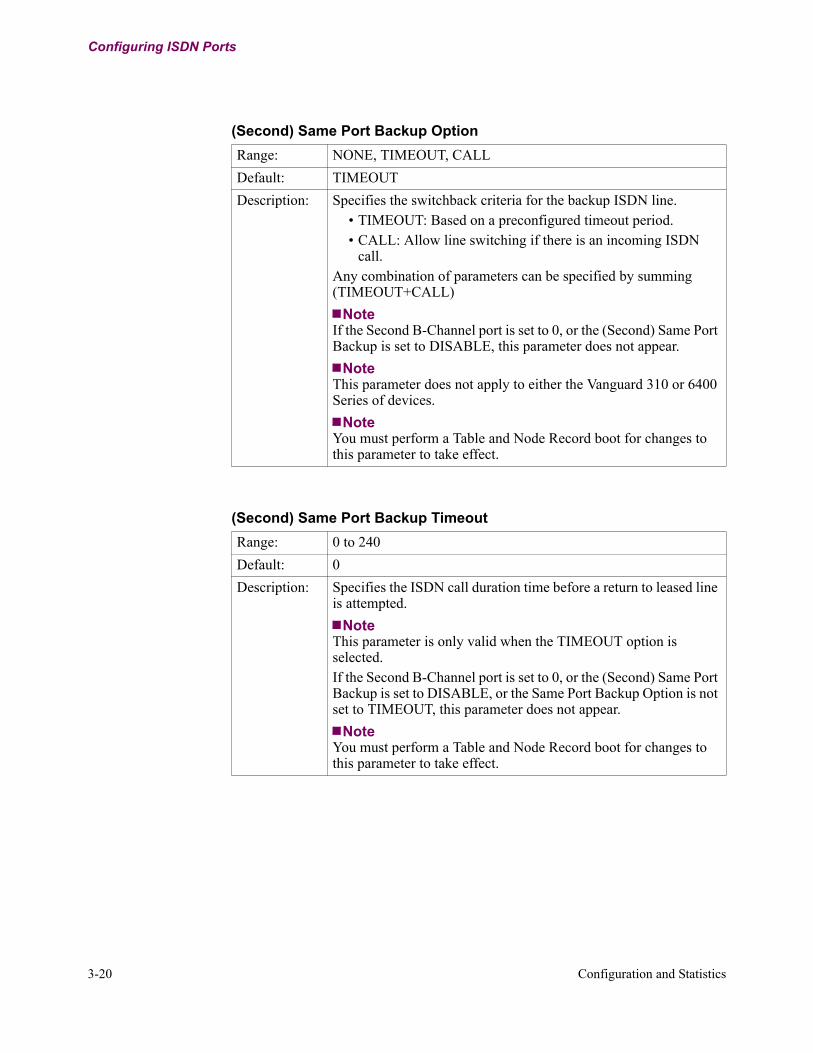
3-20 Configuration and Statistics
Configuring ISDN Ports
(Second) Same Port Backup Option
Range: NONE, TIMEOUT, CALL
Default: TIMEOUT
Description: Specifies the switchback criteria for the backup ISDN line. • TIMEOUT: Based on a preconfigured timeout period.• CALL: Allow line switching if there is an incoming ISDN
call.Any combination of parameters can be specified by summing (TIMEOUT+CALL)
NoteIf the Second B-Channel port is set to 0, or the (Second) Same Port Backup is set to DISABLE, this parameter does not appear.
NoteThis parameter does not apply to either the Vanguard 310 or 6400 Series of devices.
NoteYou must perform a Table and Node Record boot for changes to this parameter to take effect.
(Second) Same Port Backup Timeout
Range: 0 to 240
Default: 0
Description: Specifies the ISDN call duration time before a return to leased line is attempted.
NoteThis parameter is only valid when the TIMEOUT option is selected.If the Second B-Channel port is set to 0, or the (Second) Same Port Backup is set to DISABLE, or the Same Port Backup Option is not set to TIMEOUT, this parameter does not appear.
NoteYou must perform a Table and Node Record boot for changes to this parameter to take effect.

Configuration and Statistics 3-21
T0103-06, Revision I Release 7.3
Configuring ISDN Ports
(Second) Line Speed
Range: Vanguard 6400 Series: 56K, 64KVanguard 6520/6560: 64KOther Vanguard Products: 56K, 64K
Default: Vanguard 6400 Series: 56KVanguard 6520/6560: 64KOther Vanguard Products: 56K
Description: Specifies the line speed for the ISDN (Second) B-Channel.
NoteIf the first line speed is set to 112K or 128K, both (First) B and (Second) 2 channels will be used together to carry traffic (a form of bonding). (First) B and (Second) B relative timing should be guaranteed by the ISDN service provider.If the Second B-Channel port is set to 0, this parameter does not appear.
NoteYou must perform a Table and Node Record boot for changes to this parameter to take effect.
(Second) Terminal Endpoint Identifier (TEI)
Range: 0 to 63, 127, 255
Default: 127
Description: Specifies the Terminal Endpoint Identifier. This value is given by your ISDN service provider.
• 127 indicates automatic TEI negotiation. • 255 indicates the next available TEI is used.
NoteIf the Second B-Channel port is set to 0, (Second) Access Type is Permanent, or for international switch types, this parameter does not appear.
NoteYou must perform an ISDN boot for changes to this parameter to take effect.

3-22 Configuration and Statistics
Configuring ISDN Ports
(Second) Service Profile ID
Range: 0 to 20 BCD. Use the space character to blank the field
Default: blank
Description: Specifies the Service Profile. It is supplied by the ISDN service provider.
NoteIf the Second B-Channel port is set to 0, or (Second) Access Type is Permanent, or Switch Type is not DMS1, 5ESS, or NI-1, this parameter does not appear.
NoteYou must perform a Table and Node Record boot for changes to this parameter to take effect.
(Second) Local Subscriber Directory Number
Range: 0 to 16 BCD. Use the space character to blank the field
Default: blank
Description: Specifies the Local Subscriber Directory Number. It is supplied by the ISDN service provider.
• For non-POTS applications, this number is used to screen incoming calls. If the Called Number ID does not match, the call is rejected. No screening takes place if the network does not supply the Called Party Number.
• For POTS applications, this number is used to direct incoming calls to the correct POTS port. If both POTS ports have one common Directory Number, ringing is initiated on the first free POTS port.
NoteIf the Second B-Channel port is set to 0, or if (Second) Access Type is Permanent, this parameter does not appear.
NoteYou must perform a Table and Node Record boot for changes to this parameter to take effect.
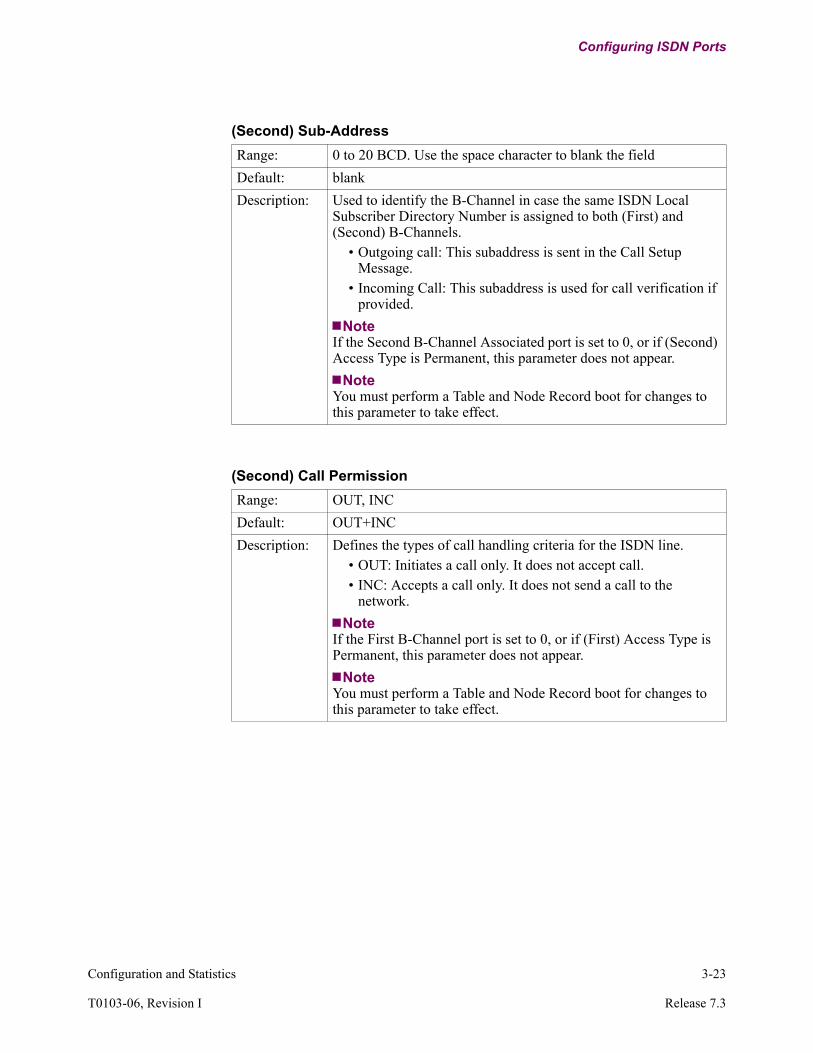
Configuration and Statistics 3-23
T0103-06, Revision I Release 7.3
Configuring ISDN Ports
(Second) Sub-Address
Range: 0 to 20 BCD. Use the space character to blank the field
Default: blank
Description: Used to identify the B-Channel in case the same ISDN Local Subscriber Directory Number is assigned to both (First) and (Second) B-Channels.
• Outgoing call: This subaddress is sent in the Call Setup Message.
• Incoming Call: This subaddress is used for call verification if provided.
NoteIf the Second B-Channel Associated port is set to 0, or if (Second) Access Type is Permanent, this parameter does not appear.
NoteYou must perform a Table and Node Record boot for changes to this parameter to take effect.
(Second) Call Permission
Range: OUT, INC
Default: OUT+INC
Description: Defines the types of call handling criteria for the ISDN line.• OUT: Initiates a call only. It does not accept call.• INC: Accepts a call only. It does not send a call to the
network.
NoteIf the First B-Channel port is set to 0, or if (First) Access Type is Permanent, this parameter does not appear.
NoteYou must perform a Table and Node Record boot for changes to this parameter to take effect.

3-24 Configuration and Statistics
Configuring ISDN Ports
(Second) Channel Selection
Range: EXCLUSIVE, PREFERRED
Default: PREFERRED
Description: Defines the channel provisioning.• EXCLUSIVE: Implies channel requested will be fixed with
the configured selection.• PREFERRED: It will be up to the network to grant a channel
for connection.
NoteIf the First B-Channel port is set to 0, or if (First) Access Type is Permanent, this parameter does not appear.
NoteYou must perform a Table and Node Record boot for changes to this parameter to take effect.
(Second) Outbound Dial Number #1
Range: 0 to 16 BCD. Use the space character to blank the field.
Default: blank
Description: Specifies the phone number to dial when establishing an ISDN outbound call.
NoteIf the Second B-Channel port is set to 0, or if (Second) Access Type is Permanent, this parameter does not appear.
NoteYou must perform a Table and Node Record boot for changes to this parameter to take effect.
(Second) Outbound Dial Number #2
Range: 0 to 16 BCD. Use the space character to blank the field
Default: blank
Description: Specifies the phone number to dial if (Second) Outbound Dial Number #1 is not available. Alternate attempts will be made between number #1 and number #2.
NoteIf the Second B-Channel port is set to 0, or if (Second) Access Type is Permanent, this parameter does not appear.
NoteYou must perform a Table and Node Record boot for changes to this parameter to take effect.

Configuration and Statistics 3-25
T0103-06, Revision I Release 7.3
Configuring ISDN Ports
(Second) Dial Retry Interval
Range: 0, 1 to 3600
Default: 30
Description: Specifies the time, in seconds, between ISDN dial attempts. If 0 is specified, the parameter is disabled.
NoteIf the Second B-Channel port is set to 0, or if (Second) Access Type is Permanent, this parameter does not appear.For the Asian ISDN Software Option, the default value is 90.
NoteYou must perform a Table and Node Record boot for changes to this parameter to take effect.
(Second) Number of Call Retries
Range: 0 to 255
Default: 5
Description: Specifies the number of times the ISDN will attempt calling, and the Call Retry Interval. If 0 is specified, the number of attempts is unlimited.
NoteIf the Second B-Channel port is set to 0, or if (Second) Access Type is Permanent, this parameter does not appear.For the Asian ISDN Software Option, the default value is 2.
NoteYou must perform a Table and Node Record boot for changes to this parameter to take effect.
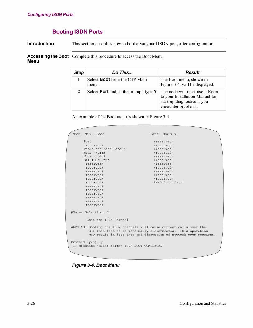
3-26 Configuration and Statistics
Configuring ISDN Ports
Booting ISDN Ports
Introduction This section describes how to boot a Vanguard ISDN port, after configuration.
Accessing the Boot Menu
Complete this procedure to access the Boot Menu.
An example of the Boot menu is shown in Figure 3-4.
Figure 3-4. Boot Menu
Step Do This... Result
1 Select Boot from the CTP Main menu.
The Boot menu, shown in Figure 3-4, will be displayed.
2 Select Port and, at the prompt, type Y. The node will reset itself. Refer to your Installation Manual for start-up diagnostics if you encounter problems.
Node: Menu: Boot Path: (Main.7)
Port (reserved)(reserved) (reserved)Table and Node Record (reserved)Node (warm) (reserved)Node (cold) (reserved)BRI ISDN Core (reserved)(reserved) (reserved)(reserved) (reserved)(reserved) (reserved)(reserved) (reserved)(reserved) (reserved)(reserved) SNMP Agent boot(reserved) (reserved) (reserved) (reserved) (reserved) (reserved)
#Enter Selection: 6
Boot the ISDN Channel
WARNING: Booting the ISDN channels will cause current calls over the BRI interface to be abnormally disconnected. This operation may result in lost data and disruption of network user sessions.
Proceed (y/n): y(1) Nodename (date) (time) ISDN BOOT COMPLETED

Configuration and Statistics 3-27
T0103-06, Revision I Release 7.3
Configuring ISDN Ports
Performing a BRI ISDN Core Boot
Follow these steps to perform a BRI ISDN Core boot:
Error Checking The Vanguard Applications Ware has an error-checking module to reduce configuration errors. The primary validation criteria are:
• At least one channel must be associated with Port 1, the physical location of the ISDN connection (that is, D-Channel, or First B-Channel, and Second B-Channel Ports cannot all be set to 0).
• D-Channel only supports X.25 port type (Q931 signalling with or without Packet D)
• On a Vanguard 100, no more than two channels can be configured.• The Associated Port for D-Channel and any B-Channel cannot be the same.• If DMS100 is selected as a switch type, auto-TEI (127) is not permitted for
Packet D-Channel.• If Switched B is selected, Port 1 must be associated to the D-Channel.• If First B-Channel Line Speed is set to 112K or 128K, Second B-Channel
cannot be associated to any port.• The Associated Port for First B and Second B cannot be the same.• At least one TEI must be configured.• If both SPIDs are blank (that is, ISDN service is 5ES Point-to-Point for a
non-initializing terminal), only one TEI can be configured.• CVL Auto Retry cannot be disabled.• If NTT or KDD switch types are selected, and the number of call retries is
greater than or equal to 2, the retry timer cannot be set to a value of less than 90 seconds.
NotePort assignments for the Vanguard 6400 Series are based on the daughter card position. Port assignments for the Vanguard 6520/6560 are based on the slot position.
Step Action Result
1 Select Boot from the CTP main menu.
The Boot menu appears.
2 Select BRI ISDN Core from the Boot menu.
The following warning is displayed:WARNING: Booting the BRI ISDN interfaces will cause current calls over the BRI interfaces to be abnormally disconnected. This operation may result in lost data and disruption of network user sessions.
Proceed (y/n): y
3 Type in: y The BRI ISDN core is rebooted.

3-28 Configuration and Statistics
Configuring ISDN Ports
ISDN BRI Voice Configuration
Introduction Configuration of the BRI Voice feature involves performing these tasks:
Configuring X.25 Refer to the Vanguard ISDN and/or X.25 Basic Configuration manuals (Part Numbers T0103-06 and T0107 respectively) for specific instructions on this activity. These port numbers can be selected for the various products supported:
NoteWhile configuring this port, you can accept all default parameter values referenced in the Vanguard ISDN and/or X.25 Basic Configuration manuals.
Configuring B-channel Virtual Ports
To configure a Voice Virtual Port, follow the procedures outlined in the Common Channel Signalling (CCS) section of the Voice Relay Manual (Part Number T0104-04). The only parameter difference you will notice is to select BRI as the access type. Set all other voice parameters to the appropriate values for you application. Remember that you can select a virtual port from the range of 100 through 254.
Task Activity
1 Configure an X.25 port corresponding to the physical port on which the D-channel signalling will be carried.
2 Configure a virtual port for each B-channel.
3 Configure an ISDN BRI Interface for each BRI Voice Daughtercard.
Product Port Selections
Vanguard 6560 7, 13, 19, 25, 31, 37, 43, 49
Vanguard 6520 13, 19, 25, 31, 37, 43, 49
Vanguard 6430/6450/6425 7, 10, 13
Vanguard 320 1, 4
Vanguard 340/342 1, 4
Vanguard 7300 Series PRI support only

Configuration and Statistics 3-29
T0103-06, Revision I Release 7.3
Configuring ISDN Ports
Accessing the BRI ISDN Interface Configuration Menu
Complete this procedure to access the BRI ISDN Interface Configuration menu.
Configuration Menu
Figure 3-5 illustrates a typical BRI Voice configuration screen.
Figure 3-5. BRI Voice Configuration Screen
Step Do This... Result
1 Select Configure from the CTP Main menu.
The Configure menu is displayed.
2 Select Configure BRI ISDN Interface from the Configure menu.
The screen for selecting the BRI ISDN interface choices appears.
3 Select BRI ISDN Interfaces from the choices.
The screen prompts you for an Entry Number that is used for CMEM identification.
ISDN BRI Interface ConfigurationEntry Number: 1/D-Channel Port Number:Format:Switch Type:User/Network Side:NT/TE Side:Clock Source:Clock MasterCalling Address Replacement:ISDN/QSIG Options:IEs to be Filtered (Outbound):Calling/Called Party Number Type:Calling/Called Party Number Plan:(First) B_Channel Port Number:(First) TEI:(First) Local Subscriber Directory Number:(Second) B-Channel_Port Number:(Second) Local Subscriber Directory Number:

3-30 Configuration and Statistics
Configuring ISDN Ports
ISDN BRI Voice and Data ConfigurationPoint Release 5 and greater allows you to use a BRI Voice Daughtercard and a BRI Data Daughtercard in the same node. This section outlines the parameters contained in the Main-> Configure-> Configure BRI ISDN Interface menu.
ISDN BRI Interface Record Menu
Figure 3-6 shows the ISDN BRI Interface Record Menu. The left column shows the parameters when Format = DATA; the right column shows the parameters when Format = VOICE:
Figure 3-6. BRI ISDN Interfaces Parameters
Node: Address: Date: Time:Menu: Configure Path:
NodeConfigure ISDN BRI Interface1. BRI ISDN Interfaces
--D-Channel Port--Format: DATA--Switch Type--Line Termination--D Packet traffic--First B-Channel Port--(First) Access Type--(First) Line Speed--(First) TEI--(First) Local Subscriber Directory Number--(First) Sub-Address--(First) Call Permission--((First) Channel Selection--((First) Outbound Dial Number #1--(First) Outbound Dial Number #2--(First) Dial Retry Interval--(First) Number of Call Retries
--D-Channel Port--Format: VOICE--Switch Type--User/Network Side--NT/TE Side--Clock Master --Calling Address Replacement--ISDN/QSIG Debug Options--IEs to be filtered (Outbound)--Calling/Called Party Number Type--Calling Called Party Number Plan--First B-Channel Port--Second B-Channel Port
Entry Number:1-3 Entry Number:1-3

Configuration and Statistics 3-31
T0103-06, Revision I Release 7.3
Configuring ISDN Ports
General BRI ISDN Interfaces Record Parameters
These records appear whether you choose Format = DATA or Format = VOICE:
Entry Number
Range: 1 to 3
Default: 1
Description: Entry number used to reference this record.
D-Channel Port
Range: • 0, 7, 13, 19, 25, 31, 37, 43, 49 for Vanguard 6560
• 13, 19, 25, 31, 37, 43, 49 for Vanguard 6520
• 7, 10, 13 for Vanguard 64xx products
• 1, 4 for Vanguard 320
• 1, 4 for Vanguard 340/342
Default: • (ISDN BRI Interface entry number *6) + 1 for
Vanguard 6520/6560
((ISDN BRI Interface entry number-1) *3) + 7 for
Vanguard 64xx
• 1 for Vanguard 320
• 1 for Vanguard 340/342
Description: Specifies the physical port associated with the ISDN D-channel.• 0: Both B-Channels’ access type is “Permanent”. No D-channeldata (Data format only).• Port No.: Packet Data on D-channel (X25) (Data format only)or B-Channel access type is “Switched” type.
NoteThis setting refers to the first port associated to the BRI. It is not a virtual port.
NotePerform a node boot to effect changes to this parameter.
NoteFor Vanguard 320, 340 and 342 - If the D-channel is configured to use Port 1, B-channel voice will use the hardware resources asso-ciated with either port 2 or port 3, whichever is available. If the D-channel is configured to use Port 4, B-channel voice will use the hardware resources associated with port 1.

3-32 Configuration and Statistics
Configuring ISDN Ports
Format
Range: DATA, VOICE
Default: DATA
Description: Specifies the format of the BRI Interface.
• Data: The interface is used for inter-nodal traffic.• Voice: The interface is used for switched voice traffic to be
compressed and packetized. Select this option to begin configuring BRI Voice.
• Transparent-CCS: D-channel sent via a TBOP connection. Pkt Voice B-channels sent as no-signalling calls.
NoteThis range is valid whenever the QSIG_Option CSK is installed.
NoteThe following parameters are what you will see when ‘Voice’ is selected.
Switch Type
Range: ETSI (for DATA)ETSI, MASTER_QSIG, SLAVE_QSIG (for VOICE)
Default: ETSI
Description: Specifies the switch type for the dial central office:• ETSI: Euro ISDN BRI (NET3)• MASTER_QSIG: Master Side QSIG PBX• SLAVE_QSIG: Slave Side QSIG PBX
NoteThe Switch Type parameter displays differently for various configurations:
• ISDN BRI Data• ISDN BRI Voice/Data• ISDN PRI/BRI Data• ISDN PRI/BRI Voice/Data

Configuration and Statistics 3-33
T0103-06, Revision I Release 7.3
Configuring ISDN Ports
DATA BRI ISDN Record Parameters
These parameters appear when Format = DATA:
D-Packet Traffic
Range: ENABLE, DISABLE
Default: DISABLE
Description: Specifies data types for transmission on the D-channel:• ENABLE: Signalling and X.25 data carried on the D-channel.• DISABLE: Only signalling data carried on the D-channel.
First Channel B Port
Range: 8, 0
Default: 8
Description Specifies the associated port’s traffic on the B-channel:• 0: No call or Terminal Endpoint Identifier (TEI) for the BRI
ISDN record parameters beginning with (First).• Port Number (8 in this case): Identifies the port’s traffic
carried on the B-channel.
NoteThis setting relates to the second port associated with this BRI interface. It is not a virtual port.
NotePerform a node boot to effect changes to this parameter.
Line Termination
Range: Hi-Z, 100-Ohm
Default: 100-Ohm
Description: Set to:• 100-Ohm - if the physical port is an end device on a
point-to-point or point-to-multipoint wiring configuration.• Hi-Z - if the physical port is an intermediate device on a
point-to-multipoint wiring configuration.
NoteTermination is configured using the Line Termination parameter on the enhanced ISDN BRI ST data daughtercard only. For more information on enhanced ISDN reference the Daughtercard Instal-lation Guide (Part Number T0020). The enhanced ISDN BRI Data card is Product Code 1152-10005. (Release 6.3 and greater)
Boot Type: Changes to the Line Termination parameter require the BRI interface to be rebooted.

3-34 Configuration and Statistics
Configuring ISDN Ports
(First) Access Type
Range: Permanent, CMD, CVL, DOV
Default: CMD
Description: Specifies the B-channel access type:• PMD: dialed B-channel service: Packet mode• CMD: dialed B-channel service: Circuit mode• CVL: dialed B-channel service: Circuit mode
(Virtual Leased Line)• Permanent: dedicated B-channel service
(First) Line Speed
Range: 56K, 64K
Default: 64k
Description: Specifies the line speed for this channel.
(First) TEI
Range: 0 to 63, 127, 255
Default: 127
Description: Specifies the TEI for this channel. Service Provider provides the TEI value.
• Select 127 for automatic TEI negotiation.• Select 255 to use Packet D TEI.
(First) Local Subscriber Directory Number
Range: 0 to 16 digits; use the SPACE bar to blank the field.
Default: blank
Description: Specifies the Local Subscriber Directory Number. Service Provider supplies the Local Subscriber Directory Number.

Configuration and Statistics 3-35
T0103-06, Revision I Release 7.3
Configuring ISDN Ports
(First) Sub-Address
Range: 0 to 20 digits; use the SPACE bar to blank the field.
Default: blank
Description: Specifies use of a sub-address:• Outgoing call: Sends sub-address in the Call Setup Message.• Incoming Call: Uses sub-address for call verification.
(First) Call Permission
Range: OUT, INC
Default: OUT+INC
Description: Specifies Caller Circuit Mode Call Permission Criteria and defines the call handling criteria types for the ISDN line:
• OUT: Only initiates a call, but it does not accept a call.• INC: Only accepts a call, but it does not send a call to the
network.
NoteThese settings can be summed as OUT+INC.
(First) Channel Selection
Range: EXCLUSIVE, PREFERRED
Default: PREFERRED
Description: Specifies channel provisioning:• EXCLUSIVE: Fixes requesteD-Channel with the configured
selection.• PREFERRED: The network grants a channel for connection.
(First) Outbound Dial Number #1
Range: 0 to 16 digits; use SPACE bar to blank the field.
Default: blank
Description: Specifies the phone number for an outbound ISDN call.

3-36 Configuration and Statistics
Configuring ISDN Ports
VOICE BRI ISDN Record Parameters
These parameters appear when Format = VOICE:
(First) Outbound Dial Number #2
Range: 0 to 16 digits; use SPACE bar to blank the field.
Default: blank
Description: Specifies the phone number for an outbound call if Outbound Call #1 is not available. When this parameter is set, the node alternates call attempts between Number #1 and Number #2.
(First) Dial Retry Timer
Range: 1 to 36,000; 0
Default: 30
Description: Defines the time in one second intervals between ISDN dial attempts.
NoteSetting this parameter to 0 disables it.
(First) Number of Call Retries
Range: 0 to 255
Default: 5
Description: Defines the number of attempts ISDN makes calling at the Call Retry Interval.
NoteSetting this parameter to zero disables it.
User Network Side
Range: User, Network
Default: User
Description: Specifies whether the BRI interface is emulating the network oruser side of the interface.
• User: The BRI interface is user-side.• Network: The BRI interface is network-side.
NoteIf QSIG is selected as the switch type (Master or Slave), this parameter does not appear.

Configuration and Statistics 3-37
T0103-06, Revision I Release 7.3
Configuring ISDN Ports
NT/TE Side
Range: TE, NT
Default: TE
Description: Specifies the interface framing:• NT: Sets the interface timing to NT. Forces selection of
internal or slave clocking.• TE: Sets the interface framing to TE. Forces the selection of
receive clocking.
Clock Source (BRI Voice Daughtercards)
Range: Internal, Slave
Default: Internal
Description: Specifies the clock source to be used instead of the clock specified in the X.25 port parameters.• Internal: take clocking from the BRI Voice Daughtercardsinternal oscillator.• Slave: takes clocking from the shared clock bus connecting all CCS interfaces.
NoteFor NT side, Internal and Slave cause the hardware to provide clocking to the interface.
NoteFor TE side, the clock source defaults to Receive (from the interface) and this parameter is not displayed.
Clock Master
Range: DISABLE, ENABLE
Default: DISABLE
Description: Specifies the clocking provided to the shared clock bus that connects all CCS interfaces:
• ENABLE: Sets this BRI interface to provide the clocking for all slave CCS interfaces.
• DISABLE: Does not use this BRI interface for clocking.
NoteEnable only one interface as Clock Master.

3-38 Configuration and Statistics
Configuring ISDN Ports
Calling Address Replacement
Range: NONE, RX, TX, RX-ONLY, TX-ONLY
Default: NONE
Description: This parameter defines the rules for Calling Number replacementfor ISDN/QSIG voice calls. If the Calling Number is going to bereplaced the replacement number comes from the B-Channel’sLocal Subscriber Directory Number.
• NONE: No calling number replacement.• RX: For an incoming call replacing the Calling Number.• TX: For an outgoing call replacing the Calling Number.• RX-ONLY: For an incoming call only if the incoming Calling
Number is blank.• TX-ONLY: For an outgoing call only if the outgoing Calling
Number is blank.
NoteCombine the above by summing (For example, RX+TX).
ISDN/QSIG Debug Options
Range: NONE, REPT, FORCE_PREF, FORCE_EXCL,BLOCK_SETUP_ACK, BLOCK_CALL_PROC, BLOCK_PROC_SETUP_ACK, BLOCK_CALL_PROGRESS, BLOCK_ALERTING, BLOCK_SENDING_COMPLETE, OVERRIDE_NUMBER_PLAN
Default: NONE
Description: Specifies these ISDN/QSIG Debug Options:•NONE : No ISDN options enabled.•REPT: Generates a 'LOW' priority report for each change in the ISDN/QSIG signaling state machine
•FORCE_PREF: Forces the Pref/Excl bit to Preferred.•FORCE_EXCL: Force the Pref/Excl bit to Exclusive.•BLOCK_SETUP_ACK: Do not send a Setup_Ack (inbound call).•BLOCK_CALL_PROC: Do not send a Call_Proceeding (inbound call).
•BLOCK_PROC_SETUP_ACK: Do not send a Call_Proceeding (inbound call) if a Setup_Ack has already been transmitted.
•BLOCK_CALL_PROGRESS: Do not send a Call_Progress (inbound call).
•BLOCK_ALERTING: Do not send a Alerting (inbound call).•BLOCK_SENDING_COMPLETE: Do not set Sending Complete.

Configuration and Statistics 3-39
T0103-06, Revision I Release 7.3
Configuring ISDN Ports
IEs to be Filtered (Outbound)
Range: 0 to 30 alphanumeric characters
Default: blank
Description: This parameter lets you configure up to 5 non-standard Information Elements (IE) to be filtered out from any outbound ISDN/QSIG message. (Applies only to Voice Calls.)Follow this syntax:
<codeset>:<IE to be filtered>, <codeset>:IE to be filtered>
For example, 00:29, 06:24 means that for code set 00, filter IE number 29 (hex) and for codeset 06 filter IE 24 (hex).To filter all non-standard IEs enter FF:FF.
Calling/Called Party Number Type
Range: Unknown, International, National Subscriber, Abbreviated
Default: National
Description: Specifies the Calling/Called Party Number Type defined by ITU-T. Use this in spoofed D-channel messages when you are interworking with non-ISDN/QSIG voice ports:
• Unknown: unknown number• International: international number• National: national number• Subscriber: subscriber number• Abbreviated: abbreviated number
Calling/Called Party Number Plan
Range: Unknown, ISDN, Telephony, Private
Default: ISDN
Description: Specifies the Calling/Called Party Number Type defined by ITU-T. Use this in spoofed D-channel messages when you are interworking with non-ISDN/QSIG voice ports:
• Unknown: unknown plan• ISDN: ISDN numbering plan (E.164)• Telephony: Standard telephone numbering plan• Private: Private numbering plan
NoteThis is used in spoofed D-channel messages when interworking with a non-ISDN/QSIG voice port.

3-40 Configuration and Statistics
Configuring ISDN Ports
First Channel B Port
Range: 100 to 254; 0
Default: 0
Description: Specifies the first virtual port’s traffic that uses the ISDN interface.
NoteA zero (0) setting disables the port.
NotePerform a node boot to effect a change to this parameter.
(First) TEI
Range: 0 to 63, 127 (ISDN)0 (QSIG)
Default: 0
Description: Specifies the Terminal Endpoint Identifier:
• Select 0 to 63 for fixed value, no TEI negotiation.• Select 127 for automatic TEI negotiation. This value is
assigned by the network side.
(First) Local Subscriber Directory Number
Range: Up to 16 characters.
Default: (blank)
Description: Specifies the number used to replace the calling party address inSETUP messages associated with the first voice virtual port,according to the replacement rules specified by the “CallingAddress Replacement” parameter.
NoteThe only valid characters are 0 through 9.
Noteuse the space bar to blank this field.

Configuration and Statistics 3-41
T0103-06, Revision I Release 7.3
Configuring ISDN Ports
Second B-Channel Port
Range: 100 to 254; 0
Default: 0
Description: Specifies the first virtual port’s traffic that uses the ISDN interface.
NoteA zero (0) setting disables the port.Perform a node boot to effect a change to this parameter.

3-42 Configuration and Statistics
ISDN Statistics
ISDN Statistics
Introduction ISDN-related information can be found in the Node Statistics, Detailed Port Statistics, and Detailed BRI ISDN Interface Stats.
Accessing the Status/Statistics Menu
To check the Statistics select Status/Statistics from the CTP main menu, and the Status/Statistics menu, shown in Figure 3-7, will be displayed. From this menu, you can select the Node Statistics, Port Statistics, or Detailed BRI ISDN Interface Stats.
Figure 3-7. Status/Statistics Menu
Viewing Node Statistics
Follow these steps to view node statistics:
Node: Menu: Status/statistics Path: (Main.5)
Node Stat Router StatsDetailed Port Stat (reserved)TFTP Stats (reserved)Detailed Link Stat (reserved)TCP Statistics (reserved)Detailed Pad Stat (reserved)Network Services Stats (reserved)Hardware Stats (reserved)(reserved) (reserved)Reset Port Stats (reserved)Reset All Stats (reserved)Software Option Statistics SNMP Statistics(reserved) (reserved) Detailed BRI ISDN Interface Stats TCP StatisticsPPP Statistics Reset PPP Statistics
#Enter Selection:
Step Action Result
1 Select Status/statistics from the CTP Main menu.
The Status/statistics menu appears.
2 Select Node Statistics from the Status/Statistics menu.
The Node Statistics screen appears.

Configuration and Statistics 3-43
T0103-06, Revision I Release 7.3
ISDN Statistics
Figures 3-8 through 3-14 show the Detailed Node Statistics screens that contain BRI ISDN-related information.
Figure 3-8. Node Statistics - Page 1
Figure 3-9. Node Statistics - Page 2
Node: Detailed Node Statistics Page: 1 of 6
Node number: Product Type: Node Serial #: PROM Revision: Code Revision: Size: 2949748 bytesFlash Revision, Current: Size: 0 bytes Bank: 2
ISDN BRI Switch Types available: N1-1, 5ESS, DMS100Flash Alternate: None Bank: 1
Last power up or reset:Last Node Boot:Last watch-dog timeout event:Last configuration change:
Power Supply Status: GOODCompressed config. memory (CMEM): 31744 bytes avail. 1150 (3%) usedUncompressed config. memory (CMEM): 65536 bytes avail. 3232 (4%) used
Press any key to continue ( ESC to exit ) ...
Node: Detailed Node Statistics Page: 2 of 6
Routing statistics: Current Maximum Date/Time MAXCalls in place: 1 1Calls per second: 0 0PVC connections: 0 0
Buffer statistics: Available Used Maximum times Date/Time MAX Used exhausedData Buffers: 5006 105 (2%) 115 (2%) -Packet Buffers: 373 40 (10%) 40 (10%) 0ManagementPacket Buffers: 53 0 (0%) 1 (1%) 0
Node Throughput: Current Maximum Date/Time MAXCharacters/sec: 0 307Packets/sec: 0 0 <none>
Front Panel LED Display: BLANK Power: ON Status: OFF Service: OFF
Press any key to continue ( ESC to exit ) ...

3-44 Configuration and Statistics
ISDN Statistics
Figure 3-10. Node Statistics - Page 3
Figure 3-11. Node Statistics - Page 4 (Vanguard 6400 Series Only)
Detailed Node Statistics Page 3 of 6
Local Memory Heap statistics: Number of bytes: Busy = 1717652, Idle = 11656, Free = 1912272
Shared Memory Heap statistics: Number of bytes: Busy = 645638, Idle = 2256, Free = 201936
Network Services NS Channel Statistics:
Number of NS Channels in use: 1 Maximum number of NS Channels used: 1 Number of NS Channels unavailable for allocation: 0
Data Compression Status: UP Data Compression Function: DSP
Press any key to continue ( ESC to exit ) . . .
Node: Detailed Node Statistics Page: 4 of 6
Motherboard: Number of ports: 16 Status: RunningAssembly Version: Serial Number:Memory Configuration:On-Board DRAM: 8 MBytes DRAM SIMM: Not InstalledOn-Board FLASH: 4 MBytes FLASH SIMM: Not Installed
Port Configuration:Port 1: NONE Port 9: NONEPort 2: NONE Port 10: ISDN-S/T D-ChannelPort 3: EIA-232-D DCE Port 11: ISDN-S/T B-ChannelPort 4: EIA-232-D DCE Port 12: ISDN-S/T B-ChannelPort 5: ETHERNET 10BASE-T Port 13: NONEPort 6: NONE Port 14: NONEPort 7: NONE Port 15: NONEPort 8: NONE Port 16: NONE
CPU utilization: 1%
Press any key to continue (ESC to exit)...

Configuration and Statistics 3-45
T0103-06, Revision I Release 7.3
ISDN Statistics
Figure 3-12. Node Statistics - Page 5
Figure 3-13. Node Statistics - ISDN BRI Data Feature Card Interface (Vanguard 6520/6560)
Node: Address: Date: Time:
Detailed Node Statistics Page: 5 of 6
Board: 0 Board Type: Motherboard Number of ports: 6 Status: RunningAssembly: 70962G01 Version: 28 Serial Number: 002987713 H.W.Rev.: AMemory Configuration: EPROM: 128 Kbytes DRAM: 8 Mbytes Current FLASH Bank: 4 Mbytes Alternate FLASH Bank: Not InstalledPort Configuration: Port 1 DIM: V.35 DTE Port 2 DIM: EIA-232-D DTECPU utilization: 2% CPU Max: 9% Assembly: N/A Version: N/A Serial Number: N/A Rev: N/A
Press any key to continue ( ESC to exit ) . . .
Node: Address: Date: Time:
Detailed Node Statistics Page: 6 of 6
Board: 5 Board Type: ISA_HOST Number of ports: 3 Status: RunningAssembly: Version: 20 Serial Number: 002993866 H.W.Rev: A
Port Configuration: Port 25 DIM: EIA-232-D DTE Port 26 DIM: EIA-232-D DTECPU utilization: 2% CPU Max: 9% Assembly: N/A Version: N/A Serial Number: N/A Rev: N/A
Board: 6 Board Type: TLAN Number of ports: 1 Status: RunningAssembly: 70971G01 Version: 16 Serial Number: 002916465 H.W.Rev: A
Press any key to continue (ESC to exit)...

3-46 Configuration and Statistics
ISDN Statistics
Figure 3-14. Node Statistics - Page 3 (Other Vanguard Products)
Viewing Detailed Port Statistics
These steps to view port statistics listed in this table are generalized for the entire range of Vanguard products.
Node: Detailed Node Statistics Page: 4 of 6
Motherboard: Number of ports: 16 Status: RunningAssembly: Version: Serial Number: Memory Configuration:On-Board DRAM: 8 Mbytes DRAM SIMM: Not InstalledOn-Boarad FLASH: 8 Mbytes FLASH SIMM: Not Installed
Port Configuration: Port 1: NONE Port 9: NONE Port 2: NONE Port 10: ISDN-S/T D-Channel Port 3: EIA-232-D DCE Port 11: ISDN-S/T B-Channel Port 4: EIA-232-D DCE Port 12: ISDN-S/T B-Channel Port 5: ETHERNET 10BASE-T Port 13: NONE Port 6: NONE Port 14: NONE Port 7: NONE Port 15: NONE Port 8: NONE Port 16: NONE
CPU utilization: 1%
Press any key to continue (ESC to exit)...
Step Action Result
1 Select Status/Statistics from the CTP main menu.
The Status/Statistics menu appears.
2 Select Detailed Port Statistics from the Status/Statistics menu.
A prompt appears.
3 Enter the number of the port you want statistics on, and press Return.
The Detailed Port Statistics screen for that port appears.

Configuration and Statistics 3-47
T0103-06, Revision I Release 7.3
ISDN Statistics
Figures 3-15 through 3-18 show the Detailed Port Statistics screens which contain BRI ISDN- related information.
Figure 3-15. Detailed Port Statistics - Page 1
Node: Detailed X25 Port Statistics: Port 1 Page: 1 of 4
Port Number: 37 Port Type: X25 Port Status: DownPort Speed: 16000 Port Stte: Disc. Phase Link Address: DCEPort Utilization In:0% Max Utilization In: 0%Port Utilization Out:0% Max Utilization Out: 0%
Call SummaryCurrent Maximum Date/Time MAX
SVC: 0 0 <none>PVC: 0 0 <none>SVC (IN): 0 0 <none>SVC (OUT): 0 0 <none>
Data Summary: Last Statistics Reset: 1(date) (time)IN OUT IN OUT
Characters: 0 0 Characters/sec: 0 0Packets: 0 0 Packets/sec: 0 0Frames: 0 0 Frames/sec: 0 0Number of Packets Queued: 0
Interface Summary: ISDN S/T BRI-6 TEI:127 SPBU: Disabled State: Setup Channel: D (Disabled)
Press any key to continue ( ESC to exit ) . . .

3-48 Configuration and Statistics
ISDN Statistics
Figure 3-16. Detailed Port Statistics - Page 2
Figure 3-17. Detailed Port Statistics - Page 3
Node:
Detailed X25 Port Statistics: Port 1 Page: 2 of 4
Port Number: 37 Port Type: X25Port Status: Down
SABM 0 0 DISC 0 0 DM
Packet Summary IN OUT 0 0
Data 0 0 Receiver Ready 0 0Receiver Not Ready 0 0 Reject Packet 0 0Call Request 0 0 Call Accept 0 0Clear Request 0 0 Clear Confirm 0 0Interrupt Request 0 0 Interrupt Conf. 0 0Reset Request 0 0 Reset Confirm 0 0Restart Request 0 0 Restart Confirm 0 0
Press any key to continue ( ESC to exit ) . . .
Node:
Detailed X25 Port Statistics: Port 1 Page: 3 of 4
Last inbound LCN: 0 <none>Inbound processing status: Processed OK, call passed to ROUT
Last Inbound Call, before processing: Called Address: Calling Address: Facilities: CUD:
Last Inbound Call, after processing: Called Address: Calling Address: Facilities: CUD:
Press any key to continue ( ESC to exit ) . . .

Configuration and Statistics 3-49
T0103-06, Revision I Release 7.3
ISDN Statistics
Figure 3-18. Detailed Port Statistics - Page 4
Viewing BRI ISDN Call Statistics
Follow these steps to view ISDN Call statistics:
Node: Detailed X25 Port Statistics: Port 1 Page: 4 of 4
Last Outbound LCN: 0 <none>Outbound processing status: Processed OK, call passed to ROUT
Last Outbound Call, before processing: Called Address: Calling Address: Facilities: CUD:
Last Outbound Call, after processing: Called Address: Calling Address: Facilities: CUD:
Press any key to continue ( ESC to exit ) . . .
Step Action Result
1 Select Status/Statistics from the CTP main menu.
The Status/Statistics menu appears.
2 Select Detailed ISDN Channel Stats from the Status/Statistics menu.
NoteFor the Vanguard 6400 Series and the Vanguard 6520/6560, you may also have to provide the Entry Number.
The ISDN Call Statistics screen appears.

3-50 Configuration and Statistics
ISDN Statistics
Figures 3-19 and 3-20 illustrate pages 1 and 2 of the ISDN Call Statistics screen.
Figure 3-19. Detailed ISDN Call Statistics - Page 1
Figure 3-20. Detailed ISDN Call Statistics - Page 2
Node: Detailed ISDN Call Statistics Page: 1 of 2
Switch Type: NI-1 BRI Interface:1Layer 1 State: ActiveStatus TEID-Channel: Enabled 21Terminal: Online 81Online 82
Current Calls:Port Connected 3 POTS1Channel Connected B1 B2TEI Connected 81 82Calling Address 5071234 NO_CID_SERCalled Address 5079898 5089897Subaddress 222333Direction Outgoing IncomingCall Status Connected ConnectedAccess Type CMD SpeechLine Speed 64K 64KCause Code 0 0Call Started date) (time) (date) (time)
Press any key to continue ( ESC to exit ) ...
Node: Detailed ISDN Call Statistics Page: 2 of 2
Last 7 calls on B1 channel:Phone Number Direction Cause Speed Port Call Started End5552000 Incoming 16 64K POTS1 (date) (time (time)5552000 Incoming 16 64K POTS1 (date) (time (time)5552000 Incoming 16 64K POTS1 (date) (time (time)
No Call No Call No Call No Call Last 7 calls on B2 channel:Phone Number Direction Cause Speed Port Call Started End
No Call No Call No Call No Call No Call No Call No Call Press any key to continue ( ESC to exit ) ...

Configuration and Statistics 3-51
T0103-06, Revision I Release 7.3
ISDN Statistics
Port States These Port States can be displayed:
• Normal: The data link is up.• Disc. Phase: The data link is down. Set during port initialization time.• Link Disc.: The data link is down. DISC has been transmitted.• Link Setup: The data link is down waiting to be brought up.
Interface Summary States
These States can appear under the Interface Summary associated with the ISDN option:
• Setup: The port has just been initialized and is waiting to be activated.• Active: The line is activated.• Inactive: The line is deactivated either due to the Telco request or no physical
line presence.• Loop Test: The line is being placed into loopback test.
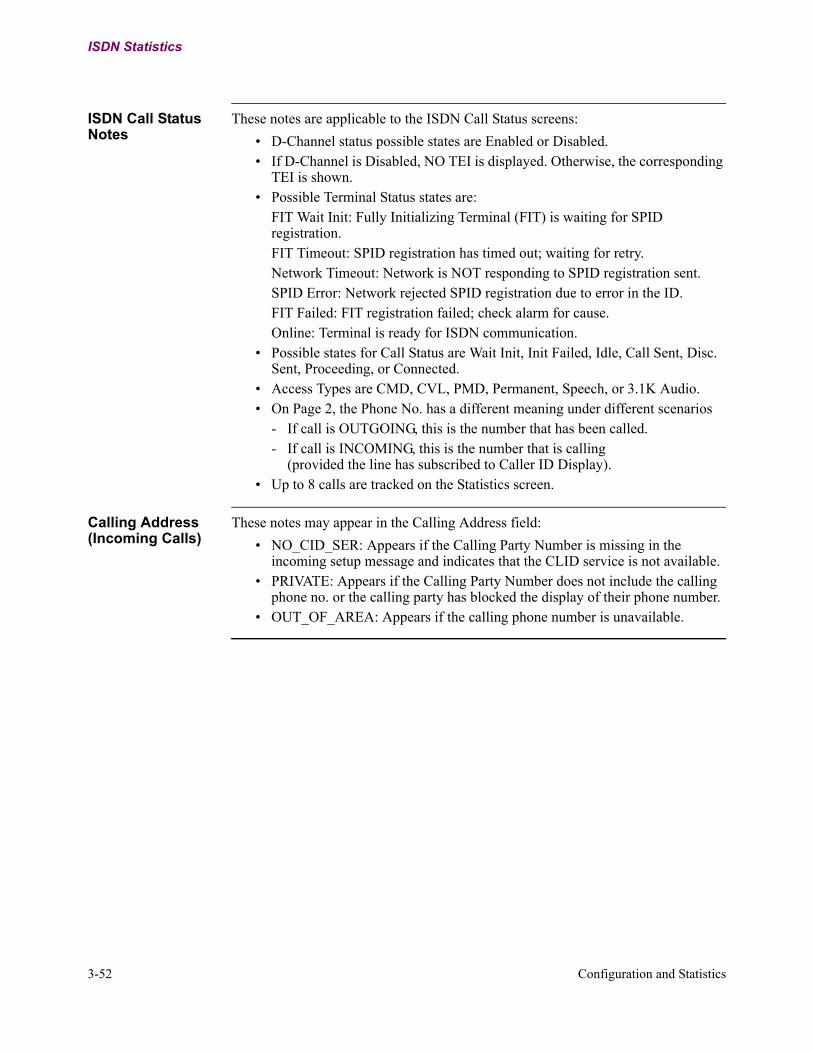
3-52 Configuration and Statistics
ISDN Statistics
ISDN Call Status Notes
These notes are applicable to the ISDN Call Status screens:
• D-Channel status possible states are Enabled or Disabled.• If D-Channel is Disabled, NO TEI is displayed. Otherwise, the corresponding
TEI is shown.• Possible Terminal Status states are:
FIT Wait Init: Fully Initializing Terminal (FIT) is waiting for SPID registration.FIT Timeout: SPID registration has timed out; waiting for retry.Network Timeout: Network is NOT responding to SPID registration sent.SPID Error: Network rejected SPID registration due to error in the ID.FIT Failed: FIT registration failed; check alarm for cause.Online: Terminal is ready for ISDN communication.
• Possible states for Call Status are Wait Init, Init Failed, Idle, Call Sent, Disc. Sent, Proceeding, or Connected.
• Access Types are CMD, CVL, PMD, Permanent, Speech, or 3.1K Audio.• On Page 2, the Phone No. has a different meaning under different scenarios
- If call is OUTGOING, this is the number that has been called.- If call is INCOMING, this is the number that is calling
(provided the line has subscribed to Caller ID Display).• Up to 8 calls are tracked on the Statistics screen.
Calling Address (Incoming Calls)
These notes may appear in the Calling Address field:
• NO_CID_SER: Appears if the Calling Party Number is missing in the incoming setup message and indicates that the CLID service is not available.
• PRIVATE: Appears if the Calling Party Number does not include the calling phone no. or the calling party has blocked the display of their phone number.
• OUT_OF_AREA: Appears if the calling phone number is unavailable.

Configuration and Statistics 3-53
T0103-06, Revision I Release 7.3
Other Menus Supporting ISDN
Other Menus Supporting ISDN
Introduction This section describes the menus that also generate information concerning the ISDN D-Channel option.
Examine Menu Figure 3-21 shows an example of the first level of the Examine menu. Figures 3-22 and 3-23 show the resulting information from the examination of the ISDN channel.
Figure 3-21. Example of Examine Menu
Node: Menu: Examine Path: (Main.2)
Node (reserved)Port (reserved)Examine Network Services (reserved)Inbound Call Translation Table (reserved)Outbound Call Translation Table (reserved)Calling Addr Translation Table (reserved)Software Key Table (reserved)TCP (reserved)NUI/Password Table (reserved)(reserved) (reserved)(reserved) (reserved)(reserved) Examine SNMP(reserved) (reserved) Examine VG-ISDN Channel (reserved) (reserved) (reserved)
#Enter Selection:

3-54 Configuration and Statistics
Other Menus Supporting ISDN
Figure 3-22. ISDN Channel Information (Page 1)
Figure 3-23. ISDN Channel Information (Page 2)
Node: Table Entry Examination: Entry 1 Page: 1 of 2
[1] *D-Channel Port: 1[1] Switch Type: NI-1[1] D Packet Traffic: DISABLE[1] *First B-Channel Port: 2[1] (First) Access Type: CMD[1] (First) Same Port Backup: DISABLE[1] (First) Line Speed: 64K[1] (First) TEI: 127[1] (First) SPID: 0555200001[1] (First) Local Subscriber Directory Number: 5552000[1] (First) Sub-Address: 222[1] (First) Outbound Dial Number #1: 5551000[1] (First) Outbound Dial Number #2: (blank)[1] (First) Dial Retry Interval: 180[1] (First) Number of Call Retries: 1[1] *Second B-Channel Port: 3[1] (Second) Access Type: CMD[1] (Second) Same Port Backup: DISABLE
Press any key to continue ( ESC to exit ) ...
Node: Table Entry Examination: Entry 1 Page: 2 of 2
[1] (Second) Line Speed: 64K[1] (Second) TEI: 127[1] (Second) SPID: 0555400001[1] (Second) Local Subscriber Directory Number: 5554000[1] (Second) Sub-Address: (blank)[1] (Second) Outbound Dial Number #1: (blank)[1] (Second) Outbound Dial Number #2: (blank)[1] (Second) Dial Retry Interval: 0[1] (Second) Number of Call Retries: 1
Press any key to continue ( ESC to exit ) ...

Configuration and Statistics 3-55
T0103-06, Revision I Release 7.3
Other Menus Supporting ISDN
List Menu Figure 3-24 is an example of the first level of the List menu. Figure 3-25 shows the resulting information from an ISDN Channel List request.
Figure 3-24. Example of List Menu
Figure 3-25. Example of ISDN Channel List Screen
Node: Menu: List Path: (Main.3)
Node (reserved)Port (reserved)List Network Services (reserved)Inbound Call Translation Table (reserved)Outbound Call Translation Table (reserved)Calling Addr Translation Table (reserved)Software Key Table (reserved)TCP (reserved)NUI/Password Table (reserved)(reserved) (reserved)(reserved) (reserved)(reserved) List SNMP(reserved) (reserved) List VG-ISDN Channel (reserved) (reserved) (reserved)
#Enter Selection:
VG-ISDN Channel List
[1], 1, NI-1, ENABLE, 21, (blank), 0, POTS1, 127, 0555100001, 5551000, OUT+INC, 0, POTS2, 127, 0555300001, 5553000, OUT+INC
Press any key to continue ( ESC to exit ) ...

3-56 Configuration and Statistics
Other Menus Supporting ISDN
ISDN Diagnostics You can test the ISDN port through the Diagnostics menu using the ISDN Tests menu item. Figure 3-26 shows the Diagnostics screen.
Figure 3-26. Diagnostics Menu
You can run an ISDN External Loopback from the ISDN Tests, as shown in Figure 3-27. This Loopback test is run under special circumstances (such as Certification Tests), and in conjunction with your ISDN service provider at the service provider’s request. This Loopback is rarely required.
Figure 3-27. ISDN Tests Screen
Node: Menu: Diagnostics Path: (Main.12)
Local Loopback V.54 Loopback 2 V.54 Loopback 3 Fatal Error Reports Logged Alarms ISDN Tests Telnet
#Enter Selection:
Node: Menu: ISDN Tests Path: (Main.12.6)
ISDN External Loopback
#Enter Selection:

Configuration and Statistics 3-57
T0103-06, Revision I Release 7.3
Other Menus Supporting ISDN
ISDN Packet Viewer
The ISDN Packet Viewer allows you to follow the message exchange on any D-channel between the Vanguard 6455 and an ISDN network. Use this tool for debugging ISDN problems in the field when an ISDN data scope is not available.
ISDN Packet Viewer CTP Menu
This menu appears when you choose ISDN Packet Viewer:
Figure 3-28. ISDN Packet Viewer CTP Menu
ISDN Packet Viewer Parameters
These parameters appear when Enable Trace Filtering = Y.
Node: Address: Date: Time:Menu: Diagnostics Path:
Local Loopback
ISDN Packet Viewer
Enable Trace Filtering (y/n): Y
--Network Clock Priority--Enable Timestamp Display--Enable ID Info Display--Pkt Viewer Filtering Options--Pkt Viewer ISDN Interface Filtering
Enable Timestamp Display
Range: ENABLE, DISABLE
Default: ENABLE
Description: Displays the timestamp of the packet traced.
Enable ID Info Display
Range: ENABLE, DISABLE
Default: ENABLE
Description: Displays the port ID, source, and destination information as part of the trace.

3-58 Configuration and Statistics
Other Menus Supporting ISDN
ISDN Packet Viewer Output
Figure 3-29 is an example of a report from the ISDN Packet Viewer:
Figure 3-29. ISDN Packet Viewer Output Example
Pkt Viewer Filtering Options
Range: NONE, LAPD, DPKT
Default: LAPD+DPKT
Description: Specifies the type of packets to display:LAPD: between BOP and LAPD.DPKT: between LAPD and X253 (SAPI-16)You can sum the settings, for example: LAPD+DPKT.
Pkt Viewer ISDN Interface Filtering
Range: 1 to 11
Default: 1
Description: Selects the ISDN interface to monitor.
6:27:00.08 Int4: Rx --> Tx
00 01 01 15
6:27:10.08 Int4: HDLC_D_ID --> L2_ID CCITT CR 3 - SETUP02 01 14 14 08 01 03 05 04 02 88 90 18 03 A9 83 93 70 08 80 35 35 35 31 3130 306:27:10.00 Int4: L2_ID --> HDLC_D_ID02 01 01 166:27:10.00 Int4: L2_ID --> HDLC_D_ID CCITT CR 3 - CONNECT00 01 14 16 08 01 83 07 18 03 A1 83 936:27:10.08 Int4: HDLC_D_ID --> L2_ID00 01 01 166:27:10.08 Int4: HDLC_D_ID --> L2_ID CCITT CR 3 - CONNECT ACK02 01 16 16 08 01 03 0F6:27:10.00 Int4: L2_ID --> HDLC_D_ID02 01 01 18Press any key to continue (ESC to exit) ...
Time stamp
Interface number Message source and destination
Hexadecimal message
representation

Configuration and Statistics 3-59
T0103-06, Revision I Release 7.3
Other Menus Supporting ISDN
ISDN Packet Viewer Output Explanation
Each message consists of two lines:
• Message header.• Hexadecimal representation of the message content.
The message header has these fields:
• Time stamp• Interface numbers: The valid numbers in a Vanguard 6455 are 1 through 11. • Message source and destination, for example:
- A message sent from a Vanguard 6455 to the ISDN line:Tx --> Rx
- A message sent from an ISDN line to a Vanguard 6455:Rx --> Tx
• Coding Standard: If the “CCITT” notation is in the message header, the message is a Q931 or a QSIG message. If “CCITT” is not in the header, it is a layer 2 message.
• Call Reference: Uses the format CR X where X is the number.
Q931 Messages These Q931 messages are decoded:
Hexadecimal Value Message Type
0x00 National
0x01 Alert
0x02 Call Proc
0x07 Connect
0x0f Connect ACK
0x03 Progress
0x05 Setup
0x0d Setup ACK
0x23 Modify
0x2f Modify Comp
0x23 Modify REJ
0x26 Resume
0x2e Resume ACK
0x22 Resume REJ
0x25 Suspend
0x2d Suspend ACK
0x21 Suspend REJ
0x20 User INFO
0x45 Disconnect

3-60 Configuration and Statistics
Other Menus Supporting ISDN
0x4d Release
0x5a Release COMPL
0x46 Restart
0x4e Restart ACK
0x60 Segment
0x79 Congestion
0x7b Information
0x62 Facility
0x6e Notify
0x7d Status
0x75 Status ENQ
Hexadecimal Value (continued) Message Type

Cause Codes and Diagnostic Codes 4-1
Chapter 4Cause Codes and Diagnostic Codes
Introduction These ETSI cause and diagnostic codes have been extracted from the ETS 300 102-1 specifications. These codes are issued by the ISDN service provider through the ISDN network connection, and are displayed in the following alarms:
• ISDN %s DISCONNECTED FROM PORT %d, CAUSE: %d• TERMINAL (%d) INITIALIZATION FAILED: %d
The %d at the end of each alarm will be a cause number from the table below.
These codes are used for troubleshooting your ISDN service. We recommend that you make a note of the cause code issued since you may need to supply the code to your service provider.
The last column of the table indicates the location that the cause code is typically generated from. In this column:
• LU: Local User• LN: Local Network• TN: Transit Network• RN: Remote Network• RU: Remote User
ISDN Cause and Diagnostic Codes
Cause Value Cause Number
Cause Diagnostic Typical Location of
Code Generation
Class Bits 765
Value Bits 4321
0 0 0 0 0 0 0 0 Valid cause code not yet received
0 0 0 0 0 0 1 1 Unallocated (unassigned) number
The destination, requested by the calling user, cannot be reached. Although the number is in a valid format, it is not currently assigned/allocated. In North America, this is a network timeout.
LN/RU

4-2 Cause Codes and Diagnostic Codes
0 0 0 0 0 1 0 2 No route to specified transit network (WAN)
The equipment sending the code has received a request to route the call through a particular transit network that it does not recognize. This is either because the network does not exist or does not service the equipment sending the code.
TN/LN
0 0 0 0 0 1 1 3 No route to destination The called user cannot be reached since the routing network does not serve the requested destination.
LN/RU
0 0 0 0 1 0 0 4 Send special information tone
0 0 0 0 1 0 1 5 Misdialled trunk prefix
0 0 0 0 1 1 0 6 Channel unacceptable This channel is not acceptable to the sending entity for use in this call.
LN
0 0 0 0 1 1 1 7 Call awarded and being delivered in an established channel
User has been awarded the incoming call, and it is being connected to a channel that is already established for similar calls (i.e., packet-mode X.25 virtual calls).
LN
0 0 0 1 0 0 0 8 Prefix 0 dialed but not allowed
0 0 0 1 0 0 1 9 Prefix 1 dialed but not allowed
0 0 0 1 0 1 0 10 Prefix 1 dialed but not required
0 0 0 1 0 1 1 11 More digits received than allowed, call is proceeding
0 0 1 0 0 0 0 16 Normal call clearing The call is being cleared because one of the users has requested that it be cleared.
RU
0 0 1 0 0 0 1 17 User busy The called user is unable to accept another call, and not because of equipment incompatibility.
RU/RN
ISDN Cause and Diagnostic Codes (continued)
Cause Value Cause Number
Cause Diagnostic Typical Location of
Code Generation
Class Bits 765
Value Bits 4321

Cause Codes and Diagnostic Codes 4-3
T0103-06, Revision I Release 7.3
0 0 1 0 0 1 0 18 No user responding The user does not respond to a call establishment message with either an alerting or connect indication within the prescribed period of time allocated (timer expired).
RN
0 0 1 0 0 1 1 19 No answer from user (user alerted)
The user has provided an alerting indication, but has not provided a connect indication within the prescribed period of time.
RN
0 0 1 0 1 0 1 21 Call rejected The equipment sending the code does not wish to accept this call, but not because the equipment is busy or incompatible.
RU
0 0 1 0 1 1 0 22 Number changed The called party number is no longer assigned. The new called party number may be included in the diagnostic field, but if the network does not support this capability, cause code #1 will be used.
LN/RU
0 0 1 0 1 1 1 23 Reverse charging rejected
0 0 1 1 0 0 0 24 Call suspended
0 0 1 1 0 0 1 25 Call resumed
0 0 1 1 0 1 0 26 Non-selected user clearing
The user has not been awarded the incoming call.
LN
0 0 1 1 0 1 1 27 Destination out of order
The destination cannot be reached because the interface is not functioning correctly. A signalling message was unable to be delivered to the remote user (i.e., a physical or data link layer failure, user equipment off-line, etc.)
RN
0 0 1 1 1 0 0 28 Invalid number format (incomplete number)
The called user cannot be reached because the called party number is not in a valid format or is not complete.
LN/RU/RN
ISDN Cause and Diagnostic Codes (continued)
Cause Value Cause Number
Cause Diagnostic Typical Location of
Code Generation
Class Bits 765
Value Bits 4321

4-4 Cause Codes and Diagnostic Codes
0 0 1 1 1 0 1 29 Facility rejected Facility requested cannot be provided by the network. (Facility identification)
LN/RU/RN
0 0 1 1 1 1 0 30 Response to STATUS ENQUIRY
This is included in the STATUS message when the reason for generating the message was the receipt of a STATUS ENQUIRY message.
LU/LN
0 0 1 1 1 1 1 31 Normal, unspecified Used to report a normal event only when no other cause in the normal class applies.
RN
0 1 0 0 0 0 1 33 Circuit out of order
0 1 0 0 0 1 0 34 No circuit/channel available
No appropriate circuit/channel is presently available to handle the call.
LN/RU/TN
0 1 0 0 0 1 1 35 Destination unattainable
0 1 0 0 1 0 1 37 Degraded service
0 1 0 0 1 1 0 38 Network (WAN) out of order
The network is not functioning correctly, and the condition is likely to last for a relatively long period of time. Immediately reattempting the call is not likely to be successful.
0 1 0 0 1 1 1 39 Transit delay range cannot be achieved
0 1 0 1 0 0 0 40 Throughput range cannot be achieved
0 1 0 1 0 0 1 41 Temporary failure The network is not functioning correctly, but the condition is not likely to last for a relatively long period of time. Immediately reattempting the call is likely to be successful. In North America, this is a SPID registration timeout. The Vanguard will retry the registration in 30 seconds.
LU/RU/RN
0 1 0 1 0 1 0 42 Switching equipment congestion
The switching equipment is experiencing a period of high traffic.
ISDN Cause and Diagnostic Codes (continued)
Cause Value Cause Number
Cause Diagnostic Typical Location of
Code Generation
Class Bits 765
Value Bits 4321

Cause Codes and Diagnostic Codes 4-5
T0103-06, Revision I Release 7.3
0 1 0 1 0 1 1 43 Access information discarded
The network could not deliver access information to the remote user as requested (i.e., user-to-user information, low or high layer compatibility, or subaddress as indicated in the diagnostic). (Discarded information element identifier(s))
RU/LN/LU
0 1 0 1 1 0 0 44 Requested circuit/channel unavailable
The circuit or channel indicated by the requesting entity cannot be provided by the other side of the interface.
LN/RU
0 1 0 1 1 0 1 45 Pre-empted
0 1 0 1 1 1 0 46 Precedence call blocked
0 1 0 1 1 1 1 47 Resources unavailable, unspecified
Used to report a resource unavailable event only when no other cause in the resource unavailable class applies.
0 1 1 0 0 0 1 49 Quality of service unavailable
The requested quality of service cannot be provided (i.e., throughput or transit delay cannot be supported).
0 1 1 0 0 1 0 50 Requested facility not subscribed
The requested supplementary service could not be provided because the user has not completed the necessary administrative arrangements with the supporting network. (Facility identification)
RU/RN/LN
0 1 1 0 0 1 1 51 Reverse charging not allowed
0 1 1 0 1 0 0 52 Outgoing calls barred
0 1 1 0 1 0 1 53 Outgoing calls barred within CUG
0 1 1 0 1 1 0 54 Incoming calls barred
0 1 1 0 1 1 1 55 Incoming calls barred within CUG
0 1 1 1 0 0 0 56 Call waiting not subscribed
ISDN Cause and Diagnostic Codes (continued)
Cause Value Cause Number
Cause Diagnostic Typical Location of
Code Generation
Class Bits 765
Value Bits 4321

4-6 Cause Codes and Diagnostic Codes
0 1 1 1 0 0 1 57 Bearer capability not authorized
The user has requested a bearer capability which is implemented by the equipment that generated the code, but the user is not authorized to use.
LN
0 1 1 1 0 1 0 58 Bearer capability not currently available
The user has requested a bearer capability which is implemented by the equipment that generated the code, but is not available at this time.
LN
0 1 1 1 1 1 1 63 Service or option not available, unspecified
Used to report a service or option unavailable event only when no other cause in the service or option unavailable class applies.
LN
1 0 0 0 0 0 1 65 Bearer capability not implemented
The equipment sending the code does not support the bearer capability requested.
LN
1 0 0 0 0 1 0 66 Channel type not implemented
The equipment sending the code does not support the channel type requested.
1 0 0 0 0 1 1 67 Transit network selection not implemented
1 0 0 0 1 0 0 68 Message not implemented
1 0 0 0 1 0 1 69 Requested facility not implemented
The equipment sending the code does not support the supplementary service requested. (Facility identification)
RU/RN/LN
1 0 0 0 1 1 0 70 Only restricted digital information bearer capability is available
The equipment has requested an unrestricted bearer service but the equipment sending the code only supports the restricted version of the requested bearer capability.
1 0 0 1 1 1 1 79 Service or option not implemented, unspecified
Used to report a service or option unavailable event only when no other cause in the service or option unavailable class applies.
ISDN Cause and Diagnostic Codes (continued)
Cause Value Cause Number
Cause Diagnostic Typical Location of
Code Generation
Class Bits 765
Value Bits 4321
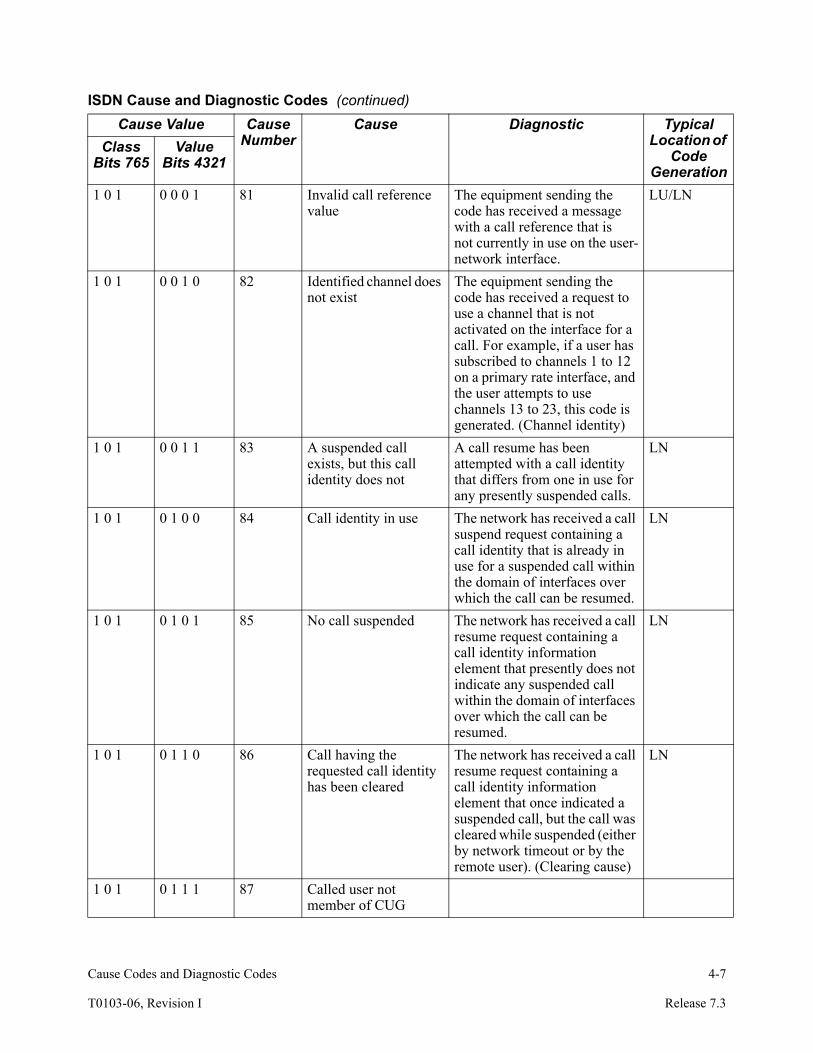
Cause Codes and Diagnostic Codes 4-7
T0103-06, Revision I Release 7.3
1 0 1 0 0 0 1 81 Invalid call reference value
The equipment sending the code has received a message with a call reference that is not currently in use on the user-network interface.
LU/LN
1 0 1 0 0 1 0 82 Identified channel does not exist
The equipment sending the code has received a request to use a channel that is not activated on the interface for a call. For example, if a user has subscribed to channels 1 to 12 on a primary rate interface, and the user attempts to use channels 13 to 23, this code is generated. (Channel identity)
1 0 1 0 0 1 1 83 A suspended call exists, but this call identity does not
A call resume has been attempted with a call identity that differs from one in use for any presently suspended calls.
LN
1 0 1 0 1 0 0 84 Call identity in use The network has received a call suspend request containing a call identity that is already in use for a suspended call within the domain of interfaces over which the call can be resumed.
LN
1 0 1 0 1 0 1 85 No call suspended The network has received a call resume request containing a call identity information element that presently does not indicate any suspended call within the domain of interfaces over which the call can be resumed.
LN
1 0 1 0 1 1 0 86 Call having the requested call identity has been cleared
The network has received a call resume request containing a call identity information element that once indicated a suspended call, but the call was cleared while suspended (either by network timeout or by the remote user). (Clearing cause)
LN
1 0 1 0 1 1 1 87 Called user not member of CUG
ISDN Cause and Diagnostic Codes (continued)
Cause Value Cause Number
Cause Diagnostic Typical Location of
Code Generation
Class Bits 765
Value Bits 4321

4-8 Cause Codes and Diagnostic Codes
1 0 1 1 0 0 0 88 Incompatible destination
The equipment sending the code has received a request to establish a call that has low or high layer compatibility attributes (i.e., data rate) that cannot be accommodated. (Incompatible parameter)
RU
1 0 1 1 0 0 1 89 Non-existent abbreviated address entry
1 0 1 1 0 1 0 90 Destination address missing, and direct call not subscribed
1 0 1 1 0 1 1 91 Invalid transit network selection (national use)
A transit network identification was received that is of the wrong format.
TN/LN
1 0 1 1 1 0 0 92 Invalid facility parameter
1 0 1 1 1 0 1 93 Mandatory information element is missing
1 0 1 1 1 1 1 95 Invalid message, unspecified
Used to report an invalid message event only when no other cause in the invalid message class applies.
LN
1 1 0 0 0 0 0 96 Mandatory information element is missing
The equipment sending the cause code has received a message that is missing an information element that must be present before the message can be processed. (Information element identifier(s))
LN/LU
1 1 0 0 0 0 1 97 Message type nonexistent or not implemented
The equipment sending the cause code received a message with a type that it does not recognize. The message is either not defined, or defined but not implemented by the equipment sending the code. (Message type)
LN/LU
ISDN Cause and Diagnostic Codes (continued)
Cause Value Cause Number
Cause Diagnostic Typical Location of
Code Generation
Class Bits 765
Value Bits 4321

Cause Codes and Diagnostic Codes 4-9
T0103-06, Revision I Release 7.3
1 1 0 0 0 1 0 98 Message not compatible with call state, or message type nonexistent or not implemented
The equipment sending the cause code received a message, but the procedures do not indicate that this is a permissible message to receive during the call state, or a STATUS message was received that indicates an incompatible call state. (Message type)
LN/LU
1 1 0 0 0 1 1 99 Information element nonexistent or not implemented
The equipment sending the cause code has received a message that includes information elements that it does not recognize. The element identifier is either not defined, or defined but not implemented by the equipment sending the code. However, the information element is not required before the message can be processed. (Information element identifier(s))
LN/LU
1 1 0 0 1 0 0 100 Invalid information element contents
The equipment sending the cause code has received an information element that it has implemented, but one or more of the fields are coded in a manner that is not recognized by the equipment sending the cause. (Information element identifier(s)) In North America, this indicates an incorrect SPID. Verify that the SPID is configured correctly; if it is, check with your ISDN service provider.
LN/LU
1 1 0 0 1 0 1 101 Message not compatible with call state
A message has been received that is incompatible with the call state. (Message type)
LN/LU
1 1 0 0 1 1 0 102 Recovery on timer expiry
A procedure has been initiated by the expiry of a timer in association with error handling procedures. (Timer number)
LN/LU
ISDN Cause and Diagnostic Codes (continued)
Cause Value Cause Number
Cause Diagnostic Typical Location of
Code Generation
Class Bits 765
Value Bits 4321
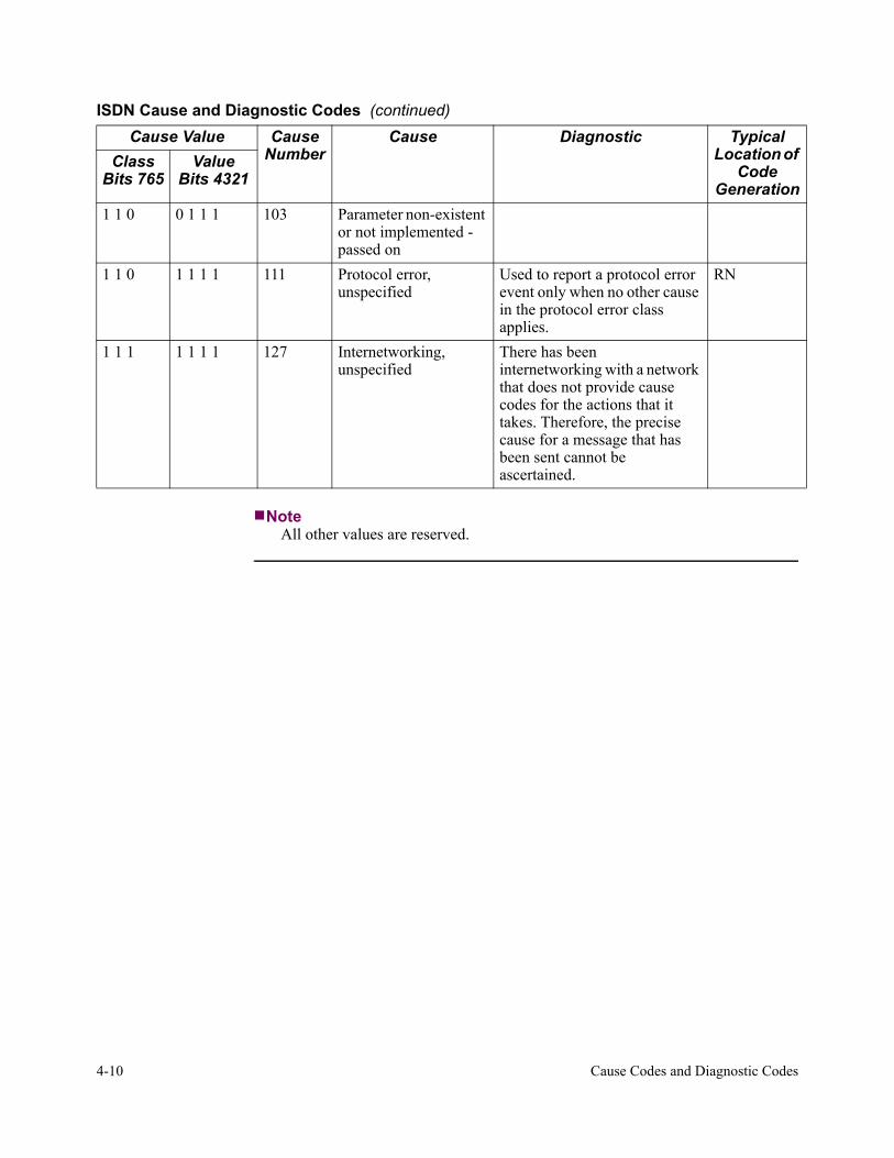
4-10 Cause Codes and Diagnostic Codes
NoteAll other values are reserved.
1 1 0 0 1 1 1 103 Parameter non-existent or not implemented - passed on
1 1 0 1 1 1 1 111 Protocol error, unspecified
Used to report a protocol error event only when no other cause in the protocol error class applies.
RN
1 1 1 1 1 1 1 127 Internetworking, unspecified
There has been internetworking with a network that does not provide cause codes for the actions that it takes. Therefore, the precise cause for a message that has been sent cannot be ascertained.
ISDN Cause and Diagnostic Codes (continued)
Cause Value Cause Number
Cause Diagnostic Typical Location of
Code Generation
Class Bits 765
Value Bits 4321
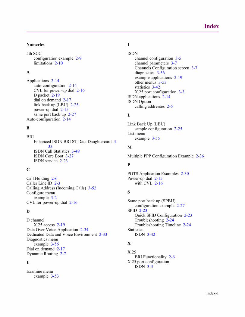
Index
Index-1
Numerics
5th SCCconfiguration example 2-9limitations 2-10
A
Applications 2-14auto-configuration 2-14CVL for power-up dial 2-16D packet 2-19dial on demand 2-17link back up (LBU) 2-25power-up dial 2-15same port back up 2-27
Auto-configuration 2-14
B
BRIEnhanced ISDN BRI ST Data Daughtercard 3-
33ISDN Call Statistics 3-49ISDN Core Boot 3-27ISDN service 2-23
C
Call Holding 2-6Caller Line ID 2-3Calling Address (Incoming Calls) 3-52Configure menu
example 3-2CVL for power-up dial 2-16
D
D channelX.25 access 2-19
Data Over Voice Application 2-34Dedicated Data and Voice Environment 2-33Diagnostics menu
example 3-56Dial on demand 2-17Dynamic Routing 2-7
E
Examine menuexample 3-53
I
ISDNchannel configuration 3-5channel parameters 3-7Channels Configuration screen 3-7diagnostics 3-56example applications 2-19other menus 3-53statistics 3-42X.25 port configuration 3-3
ISDN applications 2-14ISDN Option
calling addresses 2-6
L
Link Back Up (LBU)sample configuration 2-25
List menuexample 3-55
M
Multiple PPP Configuration Example 2-36
P
POTS Application Examples 2-30Power-up dial 2-15
with CVL 2-16
S
Same port back up (SPBU)configuration example 2-27
SPID 2-23Quick SPID Configuration 2-23Troubleshooting 2-24Troubleshooting Timeline 2-24
StatisticsISDN 3-42
X
X.25BRI Functionality 2-6
X.25 port configurationISDN 3-3


![Reasoning about Agents’ Interaction Protocols inside DCaseLPargo/papers/2004_PostProcDALT.pdf · code are integrated into the JADE (Java Agent Development Framework, [26]) middle-ware](https://img.pdfslide.net/doc/110x75/5e15a01a5fc07d574d3fd748/reasoning-about-agentsa-interaction-protocols-inside-argopapers2004postprocdaltpdf.jpg)