Embed Size (px)
Citation preview

Vanguard M™ Partial KneeMicroplasty® Instrumentation
Surgical Technique

1 | Vanguard M Partial Knee Microplasty Instrumentation Surgical Technique
This surgical technique is utilized by Keith Berend, M.D. Zimmer Biomet does not practice medicine. The treating surgeon is responsible for determining the appropriate treatment, technique(s), and product(s) for each individual patient.
Table of Contents
Preoperative Planning .............................................................................................. 2
Positioning the Limb ................................................................................................. 3
Incision ...................................................................................................................... 3
Osteophyte Excision ................................................................................................. 4
Tibial Plateau Resection ........................................................................................... 5
The Femoral Drill Holes and Alignment .................................................................... 8
Femoral Saw Cut ..................................................................................................... 10
First Milling of the Condyle ..................................................................................... 12
Equalizing the Flexion and Extension Gaps ........................................................... 13
Confirming Equality of the Flexion and Extension Gaps ........................................ 15
Preventing Impingement........................................................................................ 16
Final Preparation of the Tibial Plateau.................................................................... 17
Final Trial Reduction ............................................................................................... 18
Cementing the Components .................................................................................. 21
Indications and Full Prescribing Information ......................................................... 23
2 | Vanguard M Partial Knee Microplasty Instrumentation Surgical Technique
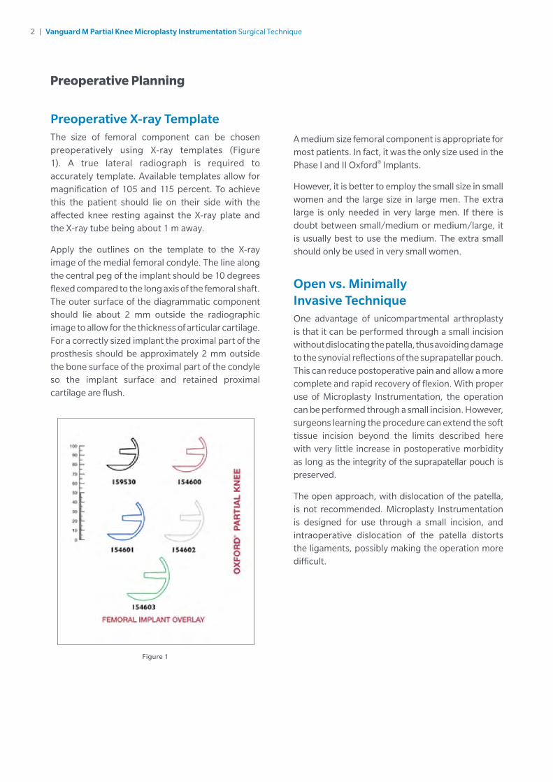
Preoperative X-ray TemplateThe size of femoral component can be chosen preoperatively using X-ray templates (Figure 1). A true lateral radiograph is required to accurately template. Available templates allow for magnification of 105 and 115 percent. To achieve this the patient should lie on their side with the affected knee resting against the X-ray plate and the X-ray tube being about 1 m away.
Apply the outlines on the template to the X-ray image of the medial femoral condyle. The line along the central peg of the implant should be 10 degrees flexed compared to the long axis of the femoral shaft. The outer surface of the diagrammatic component should lie about 2 mm outside the radiographic image to allow for the thickness of articular cartilage. For a correctly sized implant the proximal part of the prosthesis should be approximately 2 mm outside the bone surface of the proximal part of the condyle so the implant surface and retained proximal cartilage are flush.
A medium size femoral component is appropriate for most patients. In fact, it was the only size used in the Phase I and II Oxford® Implants.
However, it is better to employ the small size in small women and the large size in large men. The extra large is only needed in very large men. If there is doubt between small/medium or medium/large, it is usually best to use the medium. The extra small should only be used in very small women.
Open vs. Minimally Invasive TechniqueOne advantage of unicompartmental arthroplasty is that it can be performed through a small incision without dislocating the patella, thus avoiding damage to the synovial reflections of the suprapatellar pouch. This can reduce postoperative pain and allow a more complete and rapid recovery of flexion. With proper use of Microplasty Instrumentation, the operation can be performed through a small incision. However, surgeons learning the procedure can extend the soft tissue incision beyond the limits described here with very little increase in postoperative morbidity as long as the integrity of the suprapatellar pouch is preserved.
The open approach, with dislocation of the patella, is not recommended. Microplasty Instrumentation is designed for use through a small incision, and intraoperative dislocation of the patella distorts the ligaments, possibly making the operation more difficult.
Figure 1
Preoperative Planning
3 | Vanguard M Partial Knee Microplasty Instrumentation Surgical Technique
110˚
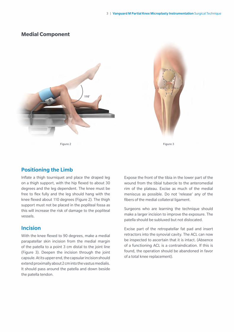
Figure 2 Figure 3
Positioning the LimbInflate a thigh tourniquet and place the draped leg on a thigh support, with the hip flexed to about 30 degrees and the leg dependent. The knee must be free to flex fully and the leg should hang with the knee flexed about 110 degrees (Figure 2). The thigh support must not be placed in the popliteal fossa as this will increase the risk of damage to the popliteal vessels.
IncisionWith the knee flexed to 90 degrees, make a medial parapatellar skin incision from the medial margin of the patella to a point 3 cm distal to the joint line (Figure 3). Deepen the incision through the joint capsule. At its upper end, the capsular incision should extend proximally about 2 cm into the vastus medialis. It should pass around the patella and down beside the patella tendon.
Expose the front of the tibia in the lower part of the wound from the tibial tubercle to the anteromedial rim of the plateau. Excise as much of the medial meniscus as possible. Do not ‘release’ any of the fibers of the medial collateral ligament.
Surgeons who are learning the technique should make a larger incision to improve the exposure. The patella should be subluxed but not dislocated.
Excise part of the retropatellar fat pad and insert retractors into the synovial cavity. The ACL can now be inspected to ascertain that it is intact. (Absence of a functioning ACL is a contraindication. If this is found, the operation should be abandoned in favor of a total knee replacement).
Medial Component
4 | Vanguard M Partial Knee Microplasty Instrumentation Surgical Technique
Figure 4 Figure 5
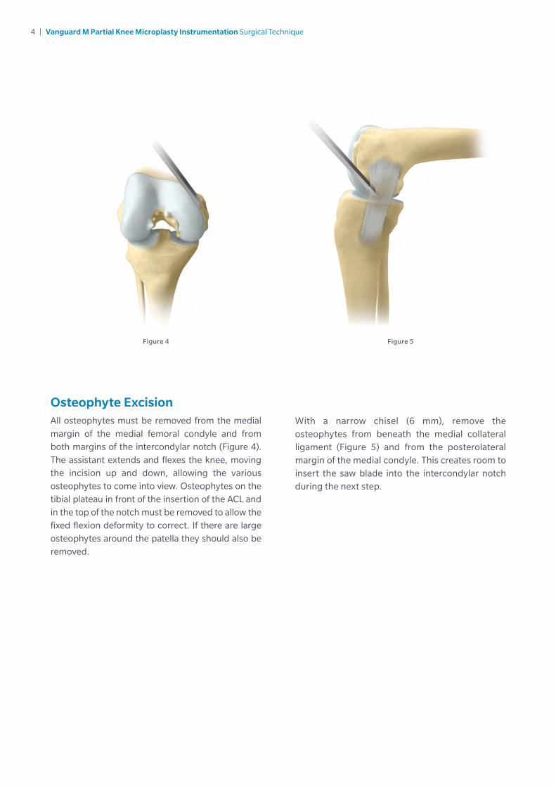
Osteophyte ExcisionAll osteophytes must be removed from the medial margin of the medial femoral condyle and from both margins of the intercondylar notch (Figure 4). The assistant extends and flexes the knee, moving the incision up and down, allowing the various osteophytes to come into view. Osteophytes on the tibial plateau in front of the insertion of the ACL and in the top of the notch must be removed to allow the fixed flexion deformity to correct. If there are large osteophytes around the patella they should also be removed.
With a narrow chisel (6 mm), remove the osteophytes from beneath the medial collateral ligament (Figure 5) and from the posterolateral margin of the medial condyle. This creates room to insert the saw blade into the intercondylar notch during the next step.

5 | Vanguard M Partial Knee Microplasty Instrumentation Surgical Technique
Tibial Plateau ResectionWith the knee in flexion, insert the femoral sizing spoon (based on preoperative estimate sizing) starting with 1 mm spoon. With all retraction removed, assess the ligament tension. Usually the 1 mm thick femoral sizing spoon achieves the proper ligament tension, but if it does not replace it with a thicker sizing spoon until the proper tension is achieved. The optimal size of the femoral component is confirmed by examining the relationship of the front of the spoon and an estimate of where the cartilage surface would have been before the arthritis. The correct sizing spoon should be inserted centrally in the medial compartment.
Apply the tibial saw guide with its shaft parallel with the long axis of the tibia in both planes (Figures 6 and 7). The ankle piece should be pointing towards the anterior superior iliac spine and the standard 0 mm tibial shim should be used. The tibial saw guide has 7 degrees of posterior slope built in.
The femoral sizing spoon, tibial saw guide and G-clamp, when used together, will accurately establish the bony resection. Only the 4 G-clamp should be applied to the femoral sizing spoon and to the medial side of the tibial saw guide to ensure access to pin holes.
Manipulate the upper end of the guide so that its face lies against the exposed bone. A recess accommodates the skin and the patellar tendon laterally (Figure 7). Engage the cam, by pulling the lever downwards, to lock the three components together.
Once the G-clamp is locked holding the femoral sizing spoon and tibial saw guide in place, pin the guide.
Note: When pinning the guide, the two medial pin holes may be used to secure the guide utilizing one headed and one headless pin, or the single hole directly anterior to the shaft may be pinned to minimize the number of perforations in the tibial bone.
Once the tibial saw guide is pinned in place, unlock the G-clamp and remove along with the femoral sizing spoon.
Figure 6 Figure 7
2 cm

6 | Vanguard M Partial Knee Microplasty Instrumentation Surgical Technique
Tibial Plateau Resection (cont.)Confirm the proposed level of resection is correct. The saw cut should pass 2 or 3 mm below the deepest part of the erosion, unless the erosion is very deep in which case the cut should be above the bottom of the defect.
Use a reciprocating saw with a stiff narrow blade to make the vertical tibial saw cut. The Oxford Saw Blade Kit contains blades with markings to indicate the depth to safely divide the posterior cortex. Push the blade into the intercondylar notch close to the lateral margin of the medial femoral condyle, from which the osteophytes were removed previously. The saw cut should be just medial to the apex of the medial tibial spine. It will pass through the edge of the ACL insertion. Point the blade toward the anterior superior iliac spine or flexion plane (Figure 8).
The saw must reach the back of the tibial plateau and a little beyond. This is achieved by lining up the appropriate mark on the saw with the anterior cortex. Advance the saw vertically down until it rests on the surface of the saw guide (Figure 9). The saw must remain parallel to the guide. Do not lift the saw handle as this will dip the saw blade and increase the risk of tibial plateau fracture.
Before making the horizontal cut, insert a medial collateral ligament (MCL) retractor. Ensure this retractor is between the saw and the MCL.
Figure 8 Figure 9
7 | Vanguard M Partial Knee Microplasty Instrumentation Surgical Technique
Posterior
Anterior
Figure 10
Figure 11
Table 1
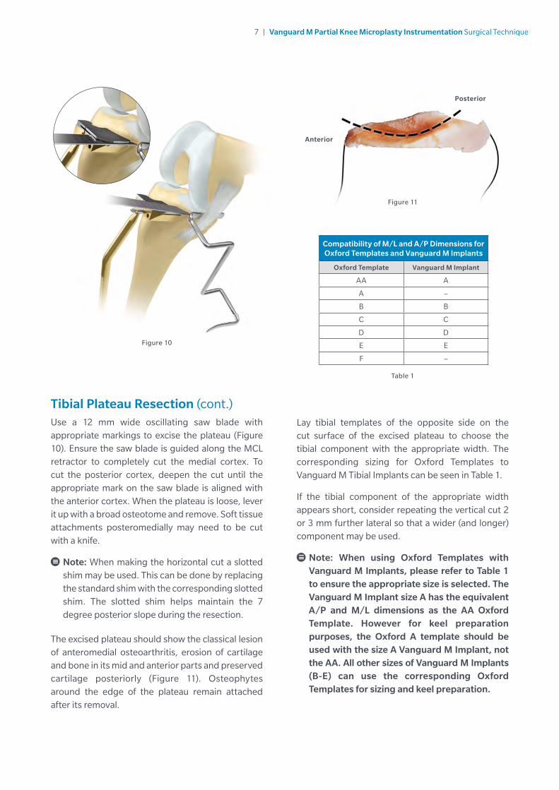
Tibial Plateau Resection (cont.)Use a 12 mm wide oscillating saw blade with appropriate markings to excise the plateau (Figure 10). Ensure the saw blade is guided along the MCL retractor to completely cut the medial cortex. To cut the posterior cortex, deepen the cut until the appropriate mark on the saw blade is aligned with the anterior cortex. When the plateau is loose, lever it up with a broad osteotome and remove. Soft tissue attachments posteromedially may need to be cut with a knife.
Note: When making the horizontal cut a slotted shim may be used. This can be done by replacing the standard shim with the corresponding slotted shim. The slotted shim helps maintain the 7 degree posterior slope during the resection.
The excised plateau should show the classical lesion of anteromedial osteoarthritis, erosion of cartilage and bone in its mid and anterior parts and preserved cartilage posteriorly (Figure 11). Osteophytes around the edge of the plateau remain attached after its removal.
Lay tibial templates of the opposite side on the cut surface of the excised plateau to choose the tibial component with the appropriate width. The corresponding sizing for Oxford Templates to Vanguard M Tibial Implants can be seen in Table 1.
If the tibial component of the appropriate width appears short, consider repeating the vertical cut 2 or 3 mm further lateral so that a wider (and longer) component may be used.
Note: When using Oxford Templates with Vanguard M Implants, please refer to Table 1 to ensure the appropriate size is selected. The Vanguard M Implant size A has the equivalent A/P and M/L dimensions as the AA Oxford Template. However for keel preparation purposes, the Oxford A template should be used with the size A Vanguard M Implant, not the AA. All other sizes of Vanguard M Implants (B-E) can use the corresponding Oxford Templates for sizing and keel preparation.
Compatibility of M/L and A/P Dimensions for Oxford Templates and Vanguard M Implants
Oxford Template Vanguard M Implant
AA A
A –
B B
C C
D D
E E
F –

8 | Vanguard M Partial Knee Microplasty Instrumentation Surgical Technique
Figure 12 Figure 13 Figure 14
The Femoral Drill Holes and AlignmentWith the knee in about 45 degrees flexion, make a hole in the intramedullary canal of the femur with the 4 mm drill. This should be completed with the 5 mm awl (Figure 12).
The hole must be situated 1 cm anterior to the anterior edge and just medial to the medial wall of the intercondylar notch (Figure 13). It should aim for the anterior superior iliac spine.
Insert the intramedullary (IM) rod until it stops against the bone (Figure 14).
Flex the knee to 90 degrees. This must be done with care, as the medial border of the patella abuts the IM rod. Using methylene blue or diathermy, draw a line down the center of the medial condyle.

9 | Vanguard M Partial Knee Microplasty Instrumentation Surgical Technique
Figure 15 Figure 16
The Femoral Drill Holes and Alignment (cont.)Insert the femoral drill guide to assess the thickness of the gap (Figure 15).
The thickness of bone removed from the tibia must be enough to accommodate the femoral drill guide set at a 4.
Note: Whenever using the femoral drill guide or feeler gauges to gap measure, the retractors must be removed. If left in, they have the effect of tightening the soft tissues, which artificially diminishes the gap.
If the correctly adjusted femoral drill guide cannot be inserted or feels tight, more bone must be excised from the tibia. To do this, remove the initial 0 mm shim from the guide using the small nub on the Oxford IM Rod Removal Hook. Once the shim is removed, revisit the vertical resection, then resect off the surface of the guide without the shim to remove 2 mm of additional bone. After additional resection, recheck the gap.
Insert the IM link into the IM rod and into the nearside/lateral hole of the femoral drill guide. This will ensure correct alignment of the guide.
There are two alignment requirements for the femoral drill guide:
1. The femoral drill guide must lie in the center of the medial condyle. This is done by ensuring the medial and lateral bollards adjacent to the 6 mm hole of the femoral drill guide are equal distance from the condyle edges. It can be confirmed by looking into the 6 mm hole and verifying the position of the methylene blue line. If the line is not central, adjust the guide position (Figure 16).
2. The femoral drill guide must be placed against the distal bone of the medial femoral condyle.
Pass the 4 mm drill through the upper hole in the guide. Drill into the bone up to its stop and leave in place. Confirm all alignments ensuring the guide does not move medially or laterally. Advance the 6 mm drill through the lower guide hole until it stops. Remove 4 mm and 6 mm drill along with the femoral drill guide.

10 | Vanguard M Partial Knee Microplasty Instrumentation Surgical Technique
Figure 18
Femoral Saw CutInsert the posterior resection guide into the drilled holes and tap home (Figure 17).
Insert a retractor to protect the MCL. Using the 12 mm broad oscillating saw, excise the posterior femoral condyle. The saw blade should be bent slightly by dropping the saw to ensure it is guided by the underside of the posterior resection guide (Figure 18). Take care to avoid damage to the medial collateral and anterior cruciate ligaments.
Remove the guide with the slap hammer, ensuring that it is withdrawn in line with the femoral drill guide holes as to not damage them. Remove the posterior bone fragment.
There is now good access to the back of the joint and any remnants of the medial meniscus should be removed. In the region of the MCL, a small cuff of meniscus should be left to protect the MCL from the tibial component. The posterior horn should be completely removed.
Figure 17
11 | Vanguard M Partial Knee Microplasty Instrumentation Surgical Technique
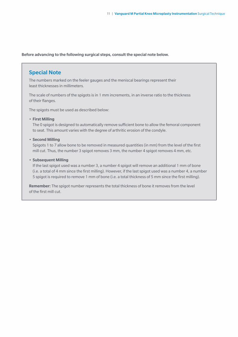
Before advancing to the following surgical steps, consult the special note below.
Special NoteThe numbers marked on the feeler gauges and the meniscal bearings represent their least thicknesses in millimeters.
The scale of numbers of the spigots is in 1 mm increments, in an inverse ratio to the thickness of their flanges.
The spigots must be used as described below:
• First Milling The 0 spigot is designed to automatically remove sufficient bone to allow the femoral component to seat. This amount varies with the degree of arthritic erosion of the condyle.
• Second Milling Spigots 1 to 7 allow bone to be removed in measured quantities (in mm) from the level of the first mill cut. Thus, the number 3 spigot removes 3 mm, the number 4 spigot removes 4 mm, etc.
• Subsequent Milling If the last spigot used was a number 3, a number 4 spigot will remove an additional 1 mm of bone (i.e. a total of 4 mm since the first milling). However, if the last spigot used was a number 4, a number 5 spigot is required to remove 1 mm of bone (i.e. a total thickness of 5 mm since the first milling).
Remember: The spigot number represents the total thickness of bone it removes from the level of the first mill cut.

12 | Vanguard M Partial Knee Microplasty Instrumentation Surgical Technique
Figure 19
Figure 20
Figure 21
First Milling of the CondyleInsert the 0 spigot, which has the thickest flange, into the large drill hole and tap until the flange abuts the bone (Figure 19). The 0 spigot is the only spigot that may be tapped into place. All other spigots should be placed and seated by finger pressure.
By extending the knee slightly and retracting the soft tissues, maneuver the spherical cutter onto the spigot (Figure 20) and into the wound so that the teeth touch the bone (Figure 21). Take care to avoid trapping soft tissues.
When milling, push firmly in the direction of the spigot axis, taking care not to tilt the mill. Mill until the cutter will no longer advance and the spigot can be seen, in the window, to have reached its end stop.
If in doubt, continue to mill; the mill cannot continue beyond the amount permitted by the collar of the selected spigot.
13 | Vanguard M Partial Knee Microplasty Instrumentation Surgical Technique
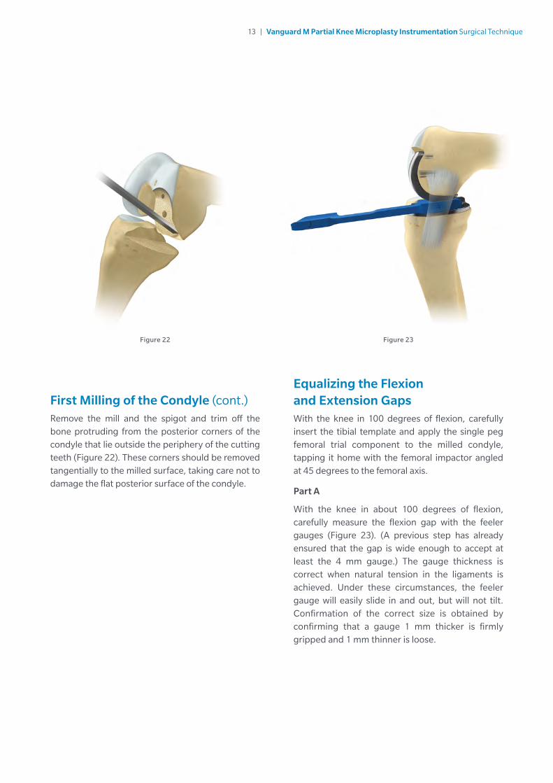
Figure 22 Figure 23
Equalizing the Flexion and Extension GapsWith the knee in 100 degrees of flexion, carefully insert the tibial template and apply the single peg femoral trial component to the milled condyle, tapping it home with the femoral impactor angled at 45 degrees to the femoral axis.
Part A
With the knee in about 100 degrees of flexion, carefully measure the flexion gap with the feeler gauges (Figure 23). (A previous step has already ensured that the gap is wide enough to accept at least the 4 mm gauge.) The gauge thickness is correct when natural tension in the ligaments is achieved. Under these circumstances, the feeler gauge will easily slide in and out, but will not tilt. Confirmation of the correct size is obtained by confirming that a gauge 1 mm thicker is firmly gripped and 1 mm thinner is loose.
First Milling of the Condyle (cont.)Remove the mill and the spigot and trim off the bone protruding from the posterior corners of the condyle that lie outside the periphery of the cutting teeth (Figure 22). These corners should be removed tangentially to the milled surface, taking care not to damage the flat posterior surface of the condyle.
14 | Vanguard M Partial Knee Microplasty Instrumentation Surgical Technique
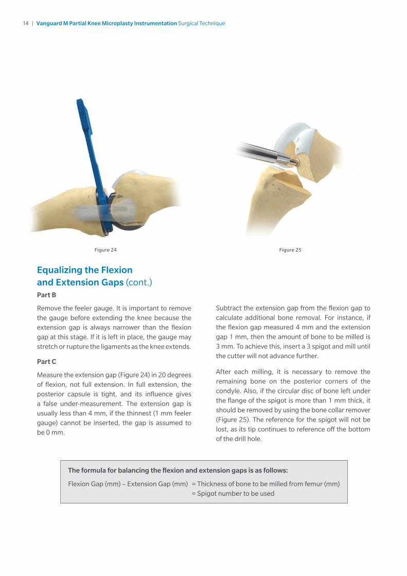
Equalizing the Flexion and Extension Gaps (cont.)Part B
Remove the feeler gauge. It is important to remove the gauge before extending the knee because the extension gap is always narrower than the flexion gap at this stage. If it is left in place, the gauge may stretch or rupture the ligaments as the knee extends.
Part C
Measure the extension gap (Figure 24) in 20 degrees of flexion, not full extension. In full extension, the posterior capsule is tight, and its influence gives a false under-measurement. The extension gap is usually less than 4 mm, if the thinnest (1 mm feeler gauge) cannot be inserted, the gap is assumed to be 0 mm.
Subtract the extension gap from the flexion gap to calculate additional bone removal. For instance, if the flexion gap measured 4 mm and the extension gap 1 mm, then the amount of bone to be milled is 3 mm. To achieve this, insert a 3 spigot and mill until the cutter will not advance further.
After each milling, it is necessary to remove the remaining bone on the posterior corners of the condyle. Also, if the circular disc of bone left under the flange of the spigot is more than 1 mm thick, it should be removed by using the bone collar remover (Figure 25). The reference for the spigot will not be lost, as its tip continues to reference off the bottom of the drill hole.
Figure 24
The formula for balancing the flexion and extension gaps is as follows:
Flexion Gap (mm) – Extension Gap (mm) = Thickness of bone to be milled from femur (mm) = Spigot number to be used
Figure 25

15 | Vanguard M Partial Knee Microplasty Instrumentation Surgical Technique
Confirming Equality of the Flexion and Extension GapsWith the tibial template and the single peg trial component in place, re-measure the flexion and extension gaps. They will usually be found to be the same (Figures 26 and 27).
If the extension gap at 20 degrees of flexion is still smaller than the flexion gap, remove more bone with the mill. This can be done, 1 mm at a time, by using the sequence of spigots. In the previous example, an additional 1 mm of bone could be removed by using a 4 spigot.
Usually the knee is balanced with a 3, 4, or 5 spigot.
Figure 26 Figure 27
16 | Vanguard M Partial Knee Microplasty Instrumentation Surgical Technique
Figure 28 Figure 29
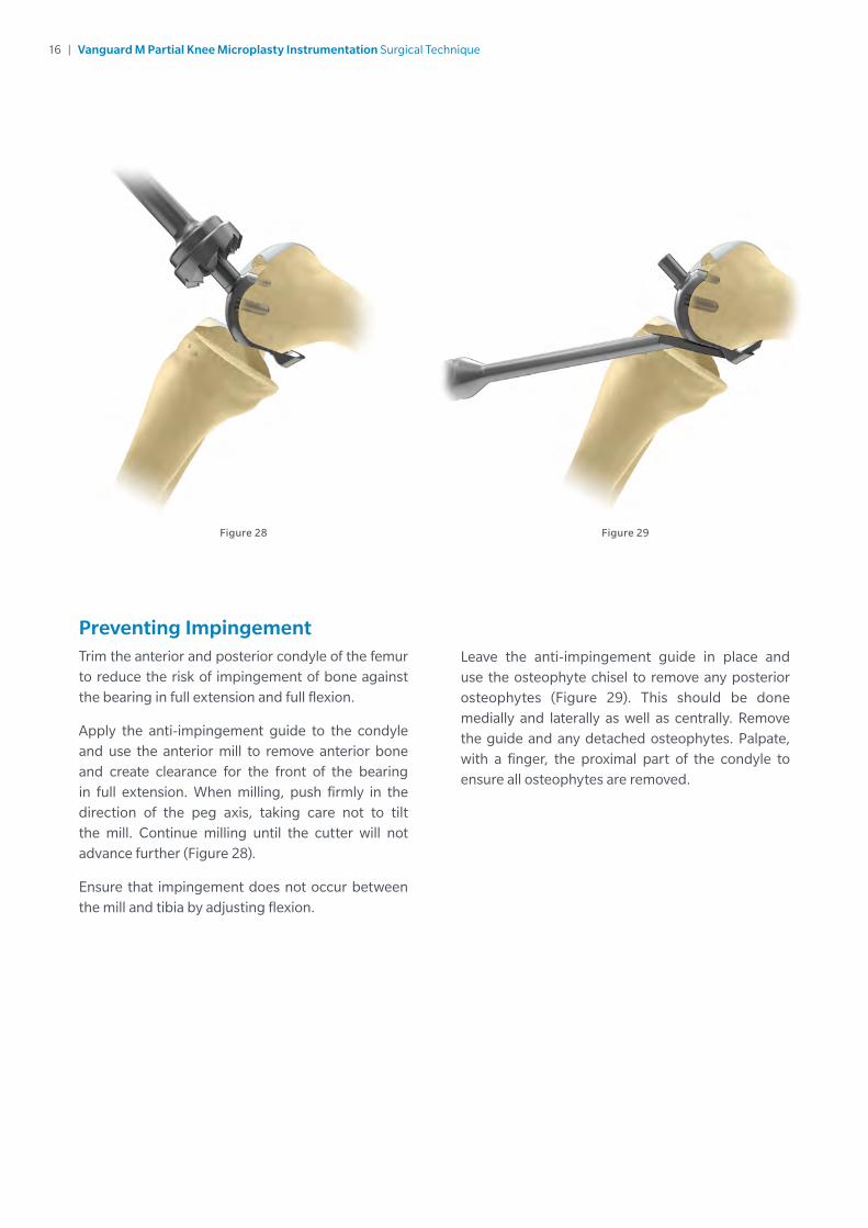
Preventing ImpingementTrim the anterior and posterior condyle of the femur to reduce the risk of impingement of bone against the bearing in full extension and full flexion.
Apply the anti-impingement guide to the condyle and use the anterior mill to remove anterior bone and create clearance for the front of the bearing in full extension. When milling, push firmly in the direction of the peg axis, taking care not to tilt the mill. Continue milling until the cutter will not advance further (Figure 28).
Ensure that impingement does not occur between the mill and tibia by adjusting flexion.
Leave the anti-impingement guide in place and use the osteophyte chisel to remove any posterior osteophytes (Figure 29). This should be done medially and laterally as well as centrally. Remove the guide and any detached osteophytes. Palpate, with a finger, the proximal part of the condyle to ensure all osteophytes are removed.
17 | Vanguard M Partial Knee Microplasty Instrumentation Surgical Technique
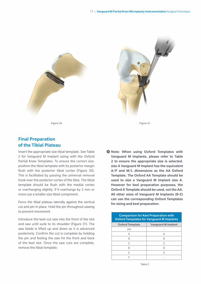
Final Preparation of the Tibial PlateauInsert the appropriate size tibial template. See Table 2 for Vanguard M Implant sizing with the Oxford Partial Knee Templates. To ensure the correct size, position the tibial template with its posterior margin flush with the posterior tibial cortex (Figure 30). This is facilitated by passing the universal removal hook over the posterior cortex of the tibia. The tibial template should be flush with the medial cortex or overhanging slightly. If it overhangs by 2 mm or more use a smaller size tibial component.
Force the tibial plateau laterally against the vertical cut and pin in place. Hold the pin throughout sawing to prevent movement.
Introduce the keel-cut saw into the front of the slot and saw until sunk to its shoulder (Figure 31). The saw blade is lifted up and down as it is advanced posteriorly. Confirm the cut is complete by holding the pin and feeling the saw hit the front and back of the keel slot. Once the saw cuts are complete, remove the tibial template.
Figure 30 Figure 31
Table 2
Note: When using Oxford Templates with Vanguard M Implants, please refer to Table 2 to ensure the appropriate size is selected. size A Vanguard M Implant has the equivalent A/P and M/L dimensions as the AA Oxford Template. The Oxford AA Template should be used to size a Vanguard M Implant size A. However for keel preparation purposes, the Oxford A Template should be used, not the AA. All other sizes of Vanguard M Implants (B-E) can use the corresponding Oxford Templates for sizing and keel preparation.
Comparison for Keel Preparation with Oxford Templates for Vanguard M Implants
Oxford Template Vanguard M Implant
AA –
A A
B B
C C
D D
E E
F –

18 | Vanguard M Partial Knee Microplasty Instrumentation Surgical Technique
Figure 32
Final Preparation of the Tibial Plateau (cont.)After removing the tibial template, excavate the groove to the correct depth by scooping out the bone with the blade of the tibial gouge, taking care not to damage the anterior and posterior cortices (Figure 32).
The safest way to prepare the back of the groove is to feel the posterior cortex with the tibial keel pick and then move it anteriorly by 5 mm before pushing down and bringing forward to empty the groove.
Final Trial ReductionInsert the trial bearing using the bearing handle (Figure 33).
Figure 33
19 | Vanguard M Partial Knee Microplasty Instrumentation Surgical Technique
Figure 34
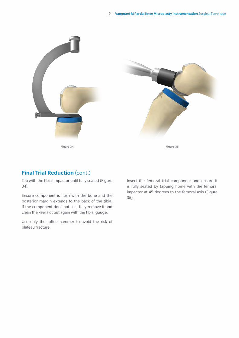
Final Trial Reduction (cont.)Tap with the tibial impactor until fully seated (Figure 34).
Ensure component is flush with the bone and the posterior margin extends to the back of the tibia. If the component does not seat fully remove it and clean the keel slot out again with the tibial gouge.
Use only the toffee hammer to avoid the risk of plateau fracture.
Figure 35
Insert the femoral trial component and ensure it is fully seated by tapping home with the femoral impactor at 45 degrees to the femoral axis (Figure 35).

20 | Vanguard M Partial Knee Microplasty Instrumentation Surgical Technique
Final Trial Reduction (cont.)With the bearing in place, manipulate the knee through a full range of motion to demonstrate stability of the joint, security of the bearing and absence of impingement (Figure 36). The thickness of the bearing should be such as to restore the ligaments to their natural tension so that, when a valgus force is applied to the knee, the artificial joint surfaces distract a millimeter or two.
Figure 36
This test should be done with the knee in 20 degrees of flexion. In full extension, the bearing will be firmly gripped because of the tight posterior capsule.
21 | Vanguard M Partial Knee Microplasty Instrumentation Surgical Technique
The Tibial Component
Place a small amount of cement on the tibial bone surface and flatten to produce a thin layer covering the whole under surface. Insert the component and press down, first posteriorly and then anteriorly, to squeeze out excess cement at the front.
Use the right-angled tibial impactor with a small mallet to complete the insertion. Ensure there is no soft tissue under the component. Remove excess cement with a Woodson Cement Currette from the margins of the component. Insert the twin peg femoral trial component to pressurize the cement. Do not fully extend or flex the leg, as this may rock the component.
Once the cement has set, remove the twin peg femoral trial component and look carefully for cement that may have extruded.
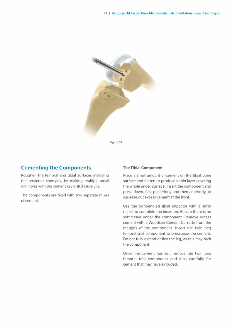
Figure 37
Cementing the ComponentsRoughen the femoral and tibial surfaces including the posterior condyles, by making multiple small drill holes with the cement key drill (Figure 37).
The components are fixed with two separate mixes of cement.
22 | Vanguard M Partial Knee Microplasty Instrumentation Surgical Technique
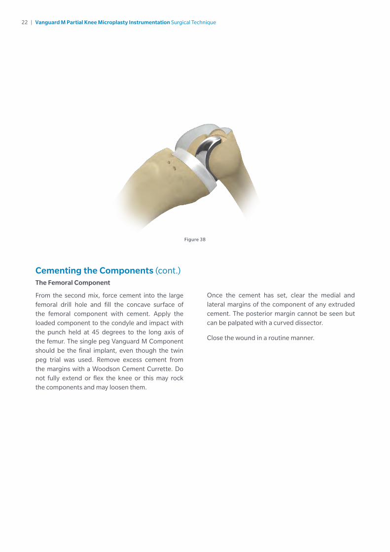
Figure 38
Cementing the Components (cont.)The Femoral Component
From the second mix, force cement into the large femoral drill hole and fill the concave surface of the femoral component with cement. Apply the loaded component to the condyle and impact with the punch held at 45 degrees to the long axis of the femur. The single peg Vanguard M Component should be the final implant, even though the twin peg trial was used. Remove excess cement from the margins with a Woodson Cement Currette. Do not fully extend or flex the knee or this may rock the components and may loosen them.
Once the cement has set, clear the medial and lateral margins of the component of any extruded cement. The posterior margin cannot be seen but can be palpated with a curved dissector.
Close the wound in a routine manner.

23 | Vanguard M Partial Knee Microplasty Instrumentation Surgical Technique
The information contained in this package insert was current on the date this brochure was printed. However, the package insert may have been revised after that date. To obtain a current package insert, please contact Biomet at the contact information provided herein.
Biomet Orthopedics 01-50-098356 East Bell Drive Revision FP.O. Box 587 Date: 2014-08Warsaw, Indiana 46581 USA
Biomet Unicondylar Knee Joint Replacement Prostheses
ATTENTION OPERATING SURGEON
DESCRIPTIONThe Unicondylar Knee Joint Replacement Prosthesis incorporates a low profile cobalt chromium or titanium femoral component and three styles of tibial components. The three styles of tibial components available include an all-polyethylene, a modular metal-backed component, and a single-piece, polyethylene/metal-backed component. Reconstruction with this implant rebalances the knee utilizing the remaining undisturbed compartmental structures and appropriate soft tissue tensions as reference points.
MaterialsFemoral Components CoCrMo Alloy/Titanium AlloyTibial Components ArCom UHMWPE/Tantalum/ Titanium/CoCrMo AlloyTibial Plates Titanium Alloy
INDICATIONSPartial replacement of the articulating surfaces of the knee when only one side of the joint is affected due to the compartmental primary degenerative or post-traumatic degenerative disease, previous tibial condyle or plateau fractures, deformity or revision of previous arthroplasty.
These devices are single-use implants intended for implantation with bone cement.
CONTRAINDICATIONSAbsolute contraindications include: infection, sepsis, and osteomyelitis.
Relative contraindications include: 1) uncooperative patient or patient with neurologic disorders who are incapable of following directions, 2) osteoporosis, 3) metabolic disorders which may impair bone formation, 4) osteomalacia, 5) distant foci of infections which may spread to the implant site, 6) rapid joint destruction, marked bone loss or bone resorption apparent on roentgenogram, 7) vascular insufficiency, muscular atrophy, neuromuscular disease, 8) incomplete or deficient soft tissue surrounding the knee.
WARNINGSImproper selection, placement, positioning, alignment and/or fixation of the implant components may result in unusual stress conditions which may lead to subsequent reduction in the service life of the prosthetic components. Malalignment of the components or inaccurate implantation can lead to excessive wear and/or failure of the implant or procedure. Inadequate preclosure cleaning (removal of surgical debris) can lead to excessive wear. Improper preoperative or intraoperative implant handling or damage (scratches, dents, etc.) can lead to crevice corrosion, fretting, fatigue fracture, and/or excessive wear. Use clean gloves when handling implants. Laboratory testing indicates that implants subjected to body fluids, surgical debris, or fatty tissue have lower adhesion strength to cement than implants handled with clean gloves. Do not modify implants. The surgeon is to be thoroughly familiar with the implants, instruments, and surgical technique prior to performing surgery.
1. The all-polyethylene and the single-piece polyethylene/metal-backed tibial components are designed to be used in treatment of low demand, less active sedentary patients. Patients that will remain active and/or overweight patients are not candidates for all- polyethylene and/or single-piece polyethylene/metal-backed tibial components.
2. Malalignment or soft tissue imbalance can place inordinate forces on the components, which may cause excessive wear to the patellar or tibial bearing articulating surfaces. Revision surgery may be required.
3. Care is to be taken to assure complete support of all parts of the device embedded in bone cement to prevent stress concentrations, which may lead to failure of the procedure. Complete preclosure cleaning and removal of bone cement debris, metallic debris, and other surgical debris at the implant site is critical to minimize wear of the implant articular surfaces. Implant fracture due to cement failure has been reported.
4. Patient smoking may result in delayed healing, non-healing and/or compromised stability in or around the placement site.
Biomet joint replacement prostheses provide the surgeon with a means of reducing pain and restoring function for many patients. While these devices are generally successful in attaining these goals, they cannot be expected to withstand the activity levels and loads of normal healthy bone and joint tissue.
Accepted practices in postoperative care are important. Failure of the patient to follow postoperative care instructions involving rehabilitation can compromise the success of the procedure. The patient is to be advised of the limitations of the reconstruction and the need for protection of the implants from full load bearing until adequate fixation and healing have occurred. Excessive, unusual and/or awkward movement and/or activity, trauma, excessive weight, and obesity have been implicated with premature failure of certain implants by loosening, fracture, dislocation, subluxation and/or wear. All-polyethylene and single-piece, polyethylene/metal-backed implants may fracture due to loosening and/or migration/subsidence. Loosening of the implants can result in increased production of wear particles, as well as accelerate damage to bone making successful revision surgery more difficult. The patient is to be made aware and warned of general surgical risks, possible adverse effects as listed, and to follow the instructions of the treating physician including follow-up visits.
Patient selection factors to be considered include: 1) need to obtain pain relief and improve function, 2) ability and willingness of the patient to follow instructions, including control of weight and activity levels, 3) a good nutritional state of the patient, and 4) the patient must have reached full skeletal maturity.
Do not reuse implants. While an implant may appear undamaged, previous stress may have created imperfections that would reduce the service life of the implant. Do not treat patients with implants that have been, even momentarily, placed in a different patient.
Device is single use only. After use, the device may be a potential biohazard. Reuse of devices labeled for single-use may result in product contamination, patient infection and/or failure of the device to perform as intended.
PRECAUTIONSSpecialized instruments are designed for Biomet joint replacement systems to aid in the accurate implantation of the prosthetic components. The use of instruments or implant components from other systems can result in inaccurate fit, incorrect sizing, excessive wear and device failure. Intraoperative fracture or breaking of instruments has been reported. Surgical instruments are subject to wear with normal usage. Instruments that have experienced extensive use or excessive force are susceptible to fracture. Surgical instruments should only be used for their intended purpose. Biomet recommends that all instruments be regularly inspected for wear and disfigurement.
All trial, packaging, and instrument components must be removed prior to closing the surgical site. Do not implant.
POSSIBLE ADVERSE EFFECTS 1. Material sensitivity reactions. Implantation of foreign material in tissues can result in
histological reactions involving various sizes of macrophages and fibroblasts. The clinical significance of this effect is uncertain, as similar changes may occur as a precursor to or during the healing process. Particulate wear debris and discoloration from metallic and polyethylene components of joint implants may be present in adjacent tissue or fluid. It has been reported that wear debris may initiate a cellular response resulting in osteolysis or osteolysis may be a result of loosening of the implant.
2. Early or late postoperative infection and/or allergic reaction. 3. Intraoperative bone perforation or fracture may occur particularly in the presence of
poor bone stock caused by osteoporosis, bone defects from previous surgery, or bone resorption.
4. Loosening and/or migration/subsidence of the implants can occur due to loss of fixation, trauma, malalignment, bone resorption, and/or excessive activity.
5. Periarticular calcification or ossification, with or without impediment of joint mobility. 6. Inadequate range of motion due to improper selection or positioning of components. 7. Undesirable shortening of limb. 8. Dislocation and subluxation due to inadequate fixation and improper positioning. Muscle
and fibrous tissue laxity can also contribute to these conditions. 9. Fatigue fracture of component can occur as a result of loss of fixation/loosening, migration/
subsidence, strenuous activity, malalignment, trauma, non-union, and/or excessive weight. 10. Fretting and crevice corrosion can occur at interfaces between components. 11. Wear and/or deformation of articulating surfaces. 12. Valgus-varus deformity. 13. Transient peroneal palsy secondary to surgical manipulation and increased joint movement
has been reported following knee arthroplasty in patients with severe flexion and valgus deformity.
14. Patellar tendon rupture and ligamentous laxity. 15. Intraoperative or postoperative bone fracture and/or postoperative pain.Intraoperative
and early postoperative complications can include: 1) damage to blood vessels, 2) temporary or permanent nerve damage resulting in pain or numbness to the affected limb, 3) cardiovascular disorders including venous thrombosis, pulmonary embolism or myocardial infarction, 4) hematoma, and 5) delayed wound healing.
Intraoperative and early postoperative complications can include: 1) damage to blood vessels, 2) temporary or permanent nerve damage resulting in pain or numbness to the affected limb, 3) cardiovascular disorders including venous thrombosis, pulmonary embolism or myocardial infarction, 4) hematoma, and 5) delayed wound healing.
MRI INFORMATIONThis device has not been evaluated for safety and compatibility in the MR environment. The devices have not been tested for heating or migration in the MR environment. The risks associated with a passive implant in an MR environment have been evaluated and are known to include heating, migration, and image artifacts at or near the implant site.
STERILITYProsthetic components are sterilized by exposure to a minimum dose of 25 kGy of gamma radiation. Single Use Only. Do Not Reuse. Do not resterilize. Do not use any component from an opened or damaged package. Do not use implants after expiration date.
Caution: Federal law (USA) restricts this device to sale by or on the order of a physician.
Comments regarding this device can be directed to Attn: Regulatory Dept., Biomet, Inc., P.O. Box 587, Warsaw, IN 46581 USA, Fax: 574-372-3968.
All trademarks herein are the property of Biomet, Inc. or its subsidiaries unless otherwise indicated.
CE Mark on the package insert (IFU) is not valid unless there is a CE Mark on the product (description) label.
Authorized Representative: Biomet U.K., Ltd. Waterton Industrial Estates Bridgend CF31 3XA, U.K.
0086

24 | Vanguard M Partial Knee Microplasty Instrumentation Surgical Technique
Notes

All content herein is protected by copyright, trademarks and other intellectual property rights owned by or licensed to Zimmer Biomet or its affiliates unless otherwise indicated, and must not be redistributed, duplicated or disclosed, in whole or in part, without the express written consent of Zimmer Biomet.
This material is intended for health care professionals and the Zimmer Biomet sales force. Distribution to any other recipient is prohibited.
For complete product information, including indications, contraindications, warnings, precautions and potential adverse effects, see the package insert and Zimmer Biomet’s website.
©2016 Zimmer Biomet
0028.1-EMEA-en-REV0716
Authorized RepresentativeBiomet UK LimitedWaterton Industrial EstateBridgend, South WalesCF31 3XA United Kingdom
Legal ManufacturerBiomet Orthopedics P.O. Box 58756 E. Bell DriveWarsaw, Indiana 46581-0587 USA
zimmerbiomet.com
CE mark on a surgical technique is not valid unless there is a CE mark on the product label.
0086