Embed Size (px)
Citation preview
Vanne 3-pièces | 3-piece ball valve
3-P
CS
CATALOGUE V15VANNE 3-PIÈCES | 3-PIECE BALL VALVE
Données fournies pour information. Evolutions possibles • Dimensions (mm) • Values given for information. Changes possible.I • 1
DN 08 à 200PN 100 / PN 16Passage Standard ou intégralBrides tournantesPlatine ISO
Size 1/4" to 8"PN 100 / PN 16Reduced or full boreRotating ends systemISO top flange
Série en acier inoxydableStainless steel series
Série en acier carboneCarbon steel series
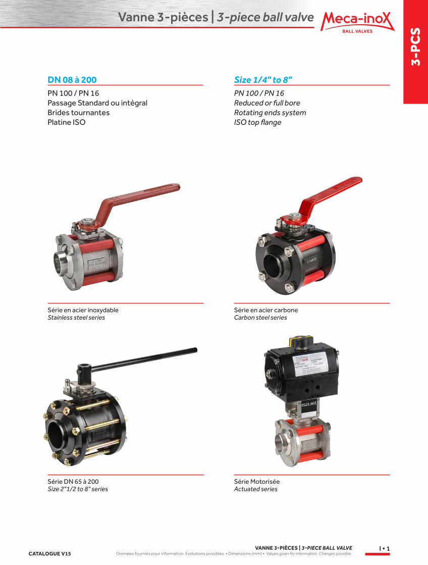
Série DN 65 à 200Size 2"1/2 to 8" series
Série MotoriséeActuated series
Vanne 3-pièces | 3-piece ball valve
VANNE 3-PIÈCES | 3-PIECE BALL VALVEDonnées fournies pour information. Evolutions possibles • Dimensions (mm) • Values given for information. Changes possible. CATALOGUE V15
I • 2
5
18
7
6 A
4 14
8 9
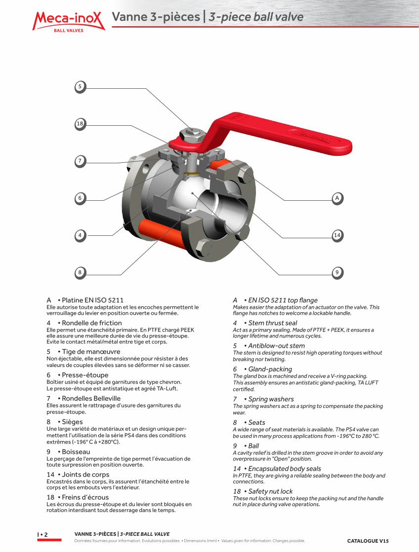
A • Platine EN ISO 5211Elle autorise toute adaptation et les encoches permettent le verrouillage du levier en position ouverte ou fermée.
4 • Rondelle de frictionElle permet une étanchéité primaire. En PTFE chargé PEEK elle assure une meilleure durée de vie du presse-étoupe. Evite le contact métal/métal entre tige et corps.
5 • Tige de manœuvreNon éjectable, elle est dimensionnée pour résister à des valeurs de couples élevées sans se déformer ni se casser.
6 • Presse-étoupeBoîtier usiné et équipé de garnitures de type chevron. Le presse-étoupe est antistatique et agréé TA-Luft.
7 • Rondelles BellevilleElles assurent le rattrapage d’usure des garnitures du presse-étoupe.
8 • SiègesUne large variété de matériaux et un design unique per-mettent l’utilisation de la série PS4 dans des conditions extrêmes (-196° C à +280°C).
9 • BoisseauLe perçage de l'empreinte de tige permet l’évacuation de toute surpression en position ouverte.
14 • Joints de corpsEncastrés dans le corps, ils assurent l’étanchéité entre le corps et les embouts vers l’extérieur.
18 • Freins d’écrousLes écrous du presse-étoupe et du levier sont bloqués en rotation interdisant tout desserrage dans le temps.
A • EN ISO 5211 top flangeMakes easier the adaptation of an actuator on the valve. This flange has notches to welcome a lockable handle.
4 • Stem thrust sealAct as a primary sealing. Made of PTFE + PEEK, it ensures a longer lifetime and numerous cycles.
5 • Antiblow-out stemThe stem is designed to resist high operating torques without breaking nor twisting.
6 • Gland-packingThe gland box is machined and receive a V-ring packing. This assembly ensures an antistatic gland-packing, TA LUFT certified.
7 • Spring washersThe spring washers act as a spring to compensate the packing wear.
8 • SeatsA wide range of seat materials is available. The PS4 valve can be used in many process applications from -196°C to 280 °C.
9 • BallA cavity relief is drilled in the stem groove in order to avoid any overpressure in "Open" position.
14 • Encapsulated body sealsIn PTFE, they are giving a reliable sealing between the body and connections.
18 • Safety nut lockThese nut locks ensure to keep the packing nut and the handle nut in place during valve operations.
Vanne 3-pièces | 3-piece ball valve
3-P
CS
CATALOGUE V15VANNE 3-PIÈCES | 3-PIECE BALL VALVE
Données fournies pour information. Evolutions possibles • Dimensions (mm) • Values given for information. Changes possible.I • 3
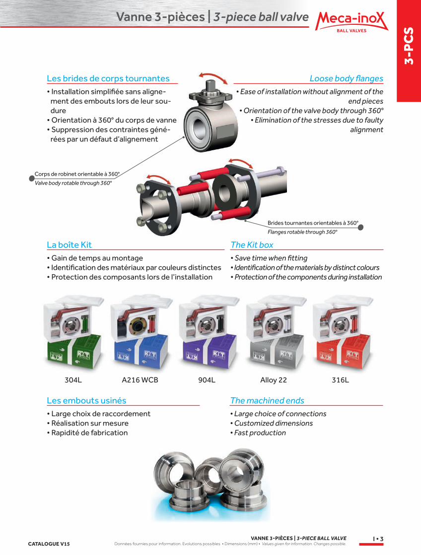
La boîte Kit• Gain de temps au montage• Identification des matériaux par couleurs distinctes• Protection des composants lors de l’installation
304L A216 WCB 904L Alloy 22 316L
The Kit box• Save time when fitting• Identification of the materials by distinct colours• Protection of the components during installation
Les embouts usinés• Large choix de raccordement• Réalisation sur mesure• Rapidité de fabrication
The machined ends• Large choice of connections• Customized dimensions• Fast production
Brides tournantes orientables à 360°
Flanges rotable through 360°
Corps de robinet orientable à 360°
Valve body rotable through 360°
Loose body flanges• Ease of installation without alignment of the
end pieces• Orientation of the valve body through 360°
• Elimination of the stresses due to faulty alignment
Les brides de corps tournantes• Installation simplifiée sans aligne-
ment des embouts lors de leur sou-dure
• Orientation à 360° du corps de vanne• Suppression des contraintes géné-
rées par un défaut d’alignement
Vanne 3-pièces | 3-piece ball valve
VANNE 3-PIÈCES | 3-PIECE BALL VALVEDonnées fournies pour information. Evolutions possibles • Dimensions (mm) • Values given for information. Changes possible. CATALOGUE V15
I • 4
Tenue au vide
La conception et la fabrication de nos robinets 2-pièces et 3-pièces garantissent une tenue à un taux de vide d’au moins de 10-3 mbar (0.75 10-3 Torr).
Vacuum resistance
Design and manufacturing of our 2-piece and 3-piece ball valve allow a vacuum capability of at least 10-3 mbar
(0,75 10-3 Torr).
Tests & essais
Directive DESPConformément aux exigences de l'annexe I de la Directive 97/23/CE DESP, nos robinets subissent des contrôles tout au long de la fabrication. Un test hydrosta-tique final vérifie la tenue sous pression.Nos essais sont réalisés suivant les normes ISO 5208 et NF EN 12266-2 conformes à la Directive DESP.
Emanations fugitivesNos robinets sont testés suivant la réquisition " TA LUFT " point 3.1.8.4. du 27/02/1986 Les résultats montrent que les taux de fuites sont nettement inférieurs aux niveaux exigés par les normes EN ISO15848-2, notamment avec les réquisitions VDI 2440_2000.
Tests
PED directiveAccording to Pressure European Directive (PED) 97/23/CE, all our ball valves are controlled during the production process. A final hydrostatic pressure test is achieved before dispatch or warehousing.Our tests are conducted according ISO 5208 international standard.
Fugitives EmissionsOur valves are tested according TA LUFT 02/27/1986 (Pt 3.1.8.4) requisition. Measure show leakage rate much lower than the level requested EN ISO15848-2 by regulations such as VDI 2440_2000.
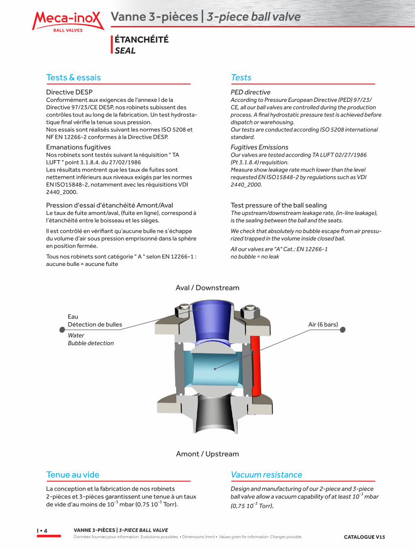
Pression d'essai d'étanchéité Amont/AvalLe taux de fuite amont/aval, (fuite en ligne), correspond à l’étanchéité entre le boisseau et les sièges.
Il est contrôlé en vérifiant qu’aucune bulle ne s’échappe du volume d’air sous pression emprisonné dans la sphère en position fermée.
Tous nos robinets sont catégorie " A " selon EN 12266-1 : aucune bulle = aucune fuite
Test pressure of the ball sealingThe upstream/downstream leakage rate, (in-line leakage), is the sealing between the ball and the seats.
We check that absolutely no bubble escape from air pressu-rized trapped in the volume inside closed ball.
All our valves are "A" Cat.: EN 12266-1 no bubble = no leak
Aval / Downstream
Amont / Upstream
ÉTANCHÉITÉ SEAL
EauDétection de bulles Air (6 bars)
WaterBubble detection
Vanne 3-pièces | 3-piece ball valve
3-P
CS
CATALOGUE V15VANNE 3-PIÈCES | 3-PIECE BALL VALVE
Données fournies pour information. Evolutions possibles • Dimensions (mm) • Values given for information. Changes possible.I • 5
7
24
4
6
NeufNew
UséWorn
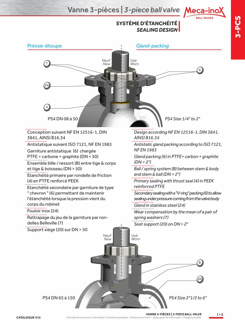
Presse-étoupe Gland-packing
Conception suivant NF EN 12516-1, DIN 3841, AINSI B16.34
Antistatique suivant ISO 7121, NF EN 1983
Garniture antistatique (6) chargée PTFE + carbone + graphite (DN < 50)
Ensemble bille / ressort (B) entre tige & corps et tige & boisseau (DN > 50)
Etanchéité primaire par rondelle de friction (4) en PTFE renforcé PEEK
Etanchéité secondaire par garniture de type " chevron " (6) permettant de maintenir l'étanchéité lorsque la pression vient du corps du robinet
Fouloir inox (24)
Rattrapage du jeu de la garniture par ron-delles Belleville (7)
Support siège (20) sur DN > 50
Design according NF EN 12516-1, DIN 3841, AINSI B16.34
Antistatic gland packing according to ISO 7121, NF EN 1983
Gland packing (6) in PTFE+ carbon + graphite (DN < 2")
Ball / spring system (B) between stem & body and stem & ball (DN > 2")
Primary sealing with thrust seal (4) in PEEK reinforced PTFE
Secondary sealing with a "V-ring" packing (6) to allow sealing under pressure coming from the valve body
Gland in stainless steel (24)
Wear compensation by the mean of a pair of spring washers (7)
Seat support (20) on DN > 2"
PS4 DN 08 à 50 PS4 Size 1/4" to 2"
PS4 DN 65 à 150 PS4 Size 2"1/2 to 6"
NeufNew
UséWorn
SYSTÈME D'ÉTANCHÉITÉ SEALING DESIGN
B
20
Vanne 3-pièces | 3-piece ball valve
VANNE 3-PIÈCES | 3-PIECE BALL VALVEDonnées fournies pour information. Evolutions possibles • Dimensions (mm) • Values given for information. Changes possible. CATALOGUE V15
I • 6
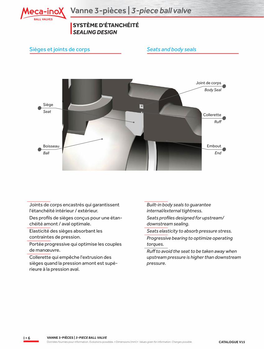
Sièges et joints de corps Seats and body seals
Joints de corps encastrés qui garantissent l'étanchéité intérieur / extérieur.
Des profils de sièges conçus pour une étan-chéité amont / aval optimale.
Elasticité des sièges absorbant les contraintes de pression.
Portée progressive qui optimise les couples de manœuvre.
Collerette qui empêche l'extrusion des sièges quand la pression amont est supé-rieure à la pression aval.
Built-in body seals to guarantee internal/external tightness.
Seats profiles designed for upstream/downstream sealing.
Seats elasticity to absorb pressure stress.
Progressive bearing to optimize operating torques.
Ruff to avoid the seat to be taken away when upstream pressure is higher than downstream pressure.
SYSTÈME D'ÉTANCHÉITÉSEALING DESIGN
Boisseau
Joint de corps
Collerette
Embout
Ball
Body Seal
Ruff
End
Siège
Seat
Vanne 3-pièces | 3-piece ball valve
3-P
CS
CATALOGUE V15VANNE 3-PIÈCES | 3-PIECE BALL VALVE
Données fournies pour information. Evolutions possibles • Dimensions (mm) • Values given for information. Changes possible.I • 7
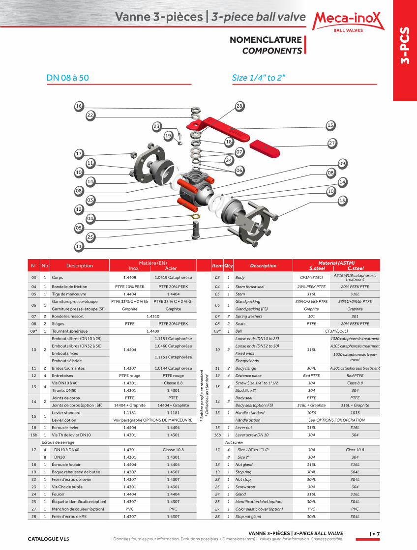
DN 08 à 50 Size 1/4" to 2"
N° ItemNb QtyDescription DescriptionMatière (EN)Inox Acier
Material (ASTM)S.steel C.steel
03 1 Corps 1.4409 1.0619 Cataphorèsé
* Sp
hère
per
çée
en s
tand
ard
* D
rille
d ba
ll as
sta
ndar
d
03 1 Body CF3M (316L) A216 WCB cataphoresis treatment
04 1 Rondelle de friction PTFE 20% PEEK PTFE 20% PEEK 04 1 Stem thrust seal 20% PEEK PTFE 20% PEEK PTFE
05 1 Tige de manœuvre 1.4404 1.4404 05 1 Stem 316L 316L
06 1Garniture presse-étoupe PTFE 33 % C + 2 % Gr PTFE 33 % C + 2 % Gr
06 1Gland packing 33%C+2%Gr PTFE 33%C+2%Gr PTFE
Garniture presse-étoupe (SF) Graphite Graphite Gland packing (FS) Graphite Graphite
07 2 Rondelles ressort 1.4310 07 2 Spring washers 301 301
08 2 Sièges PTFE PTFE 20% PEEK 08 2 Seats PTFE 20% PEEK PTFE
09* 1 Tournant sphérique 1.4409 09* 1 Ball CF3M (316L)
10 2
Embouts libres (DN10 à 25)
1.4404
1.1151 Cataphorèsé
10 2
Loose ends (DN10 to 25)
316L
1020 cataphoresis treatment
Embouts libres (DN32 à 50) 1.0460 Cataphorèsé Loose ends (DN32 to 50) A105 cataphoresis treatment
Embouts fixes1.1151 Cataphorèsé
Fixed ends 1020 cataphoresis treat-mentEmbouts à bride Flanged ends
11 2 Brides tournantes 1.4307 1.0144 Cataphorèsé 11 2 Body flange 304L A 501 cataphoresis treatment
12 4 Entretoises PTFE rouge PTFE rouge 12 4 Distance piece Red PTFE Red PTFE
13 4Vis DN10 à 40 1.4301 Classe 8.8
13 4Screw Size 1/4" to 1"1/2 304 Class 8.8
Tirants DN50 1.4301 1.4301 Stud Size 2" 304 304
14 2Joints de corps PTFE PTFE
14 2Body seal PTFE PTFE
Joints de corps (option : SF) 14404 + Graphite 14404 + Graphite Body seal (option: FS) 316L + Graphite 316L + Graphite
15 1Levier standard 1.1181 1.1181 15 1 Handle standard 1035 1035
Levier option Voir paragraphe OPTIONS DE MANŒUVRE Handle option See OPTIONS FOR OPERATION
16 1 Ecrou de levier 1.4404 1.4404 16 1 Lever nut 316L 316L
16b 1 Vis Th de levier DN10 1.4301 1.4301 16b 1 Lever screw DN 10 304 304
17
Écrous de serrage
17
Nut screw
4 DN10 à DN40 1,4301 Classe 10.8 4 Size 1/4" to 1"1/2 304 Class 10.8
8 DN50 1.4301 1.4301 8 Size 2" 304 304
18 1 Écrou de fouloir 1.4404 1.4404 18 1 Nut gland 316L 316L
19 1 Bague réhaussée de butée 1.4307 1.4307 19 1 Stop ring 304L 304L
22 1 Frein d'écrou de levier 1.4307 1.4307 22 1 Nut stop 304L 304L
23 1 Vis Chc de butée 1.4301 1.4301 23 1 Screw stop 304 304
24 1 Fouloir 1.4404 1.4404 24 1 Gland 316L 316L
25 1 Étiquette identification (option) 1.4307 1.4307 25 1 Identification label (option) 304L 304L
27 1 Manchon de couleur (option) PVC PVC 27 1 Color plastic cover (option) PVC PVC
28 1 Frein d'écrou de P.E 1.4307 1.4307 28 1 Stop nut gland 304L 304L
NOMENCLATURECOMPONENTS
16
23
17
10
08
12
05
11
22
19
11
14
03
04
25
08
10
14
09
13
18
24
07
06
15
27
28
Vanne 3-pièces | 3-piece ball valve
VANNE 3-PIÈCES | 3-PIECE BALL VALVEDonnées fournies pour information. Evolutions possibles • Dimensions (mm) • Values given for information. Changes possible. CATALOGUE V15
I • 8
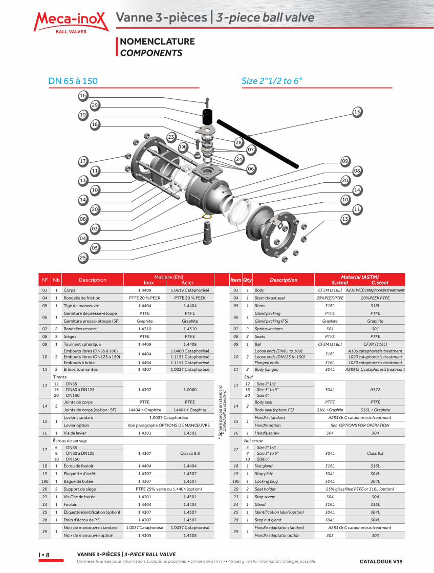
DN 65 à 150 Size 2"1/2 to 6"16
19
23
17
13
14
08
04
25
29
18
19b
11
10
20
03
05
09
20
10
13
08
14
11
28
24
07
06
15
N° ItemNb QtyDescription DescriptionMatière (EN)Inox Acier
Material (ASTM)S.steel C.steel
03 1 Corps 1.4409 1.0619 Cataphorèsé
* Sp
hère
per
çée
en s
tand
ard
* D
rille
d ba
ll as
sta
ndar
d
03 1 Body CF3M (316L) A216 WCB cataphoresis treatment
04 1 Rondelle de friction PTFE 20 % PEEK PTFE 20 % PEEK 04 1 Stem thrust seal 20%PEEK PTFE 20%PEEK PTFE
05 1 Tige de manœuvre 1.4404 1.4404 05 1 Stem 316L 316L
06 1Garniture de presse-étoupe PTFE PTFE
06 1Gland packing PTFE PTFE
Garniture presse-étoupe (SF) Graphite Graphite Gland packing (FS) Graphite Graphite
07 2 Rondelles ressort 1.4310 1.4310 07 2 Spring washers 301 301
08 2 Sièges PTFE PTFE 08 2 Seats PTFE PTFE
09 1 Tournant sphérique 1.4409 1.4409 09 1 Ball CF3M (316L) CF3M (316L)
10 2Embouts libres (DN65 à 100)
1.44041.0460 Cataphorèsé
10 2Loose ends (DN65 to 100)
316LA105 cataphoresis treatment
Embouts libres (DN125 à 150) 1.1151 Cataphorèsé Loose ends (DN125 to 150) 1020 cataphoresis treatmentEmbouts à bride 1.4404 1.1151 Cataphorèsé Flanged ends 316L 1020 cataphoresis treatment
11 2 Brides tournantes 1.4307 1.0037 Cataphorèsé 11 2 Body flanges 304L A283 Gr C cataphoresis treatment
13
Tirants
13
Stud
12 DN651.4307 1.0060
12 Size 2"1/2304L A57216 DN80 à DN125 16 Size 3" to 5"
20 DN150 20 Size 6"
14 2Joints de corps PTFE PTFE
14 2Body seal PTFE PTFE
Joints de corps (option : SF) 14404 + Graphite 14404 + Graphite Body seal (option: FS) 316L + Graphite 316L + Graphite
15 1Levier standard 1.0037 Cataphorèsé
15 1Handle standard A283 Gr C cataphoresis treatment
Levier option Voir paragraphe OPTIONS DE MANŒUVRE Handle option See OPTIONS FOR OPERATION
16 1 Vis de levier 1.4301 1.4301 16 1 Handle screw 304 304
17
Écrous de serrage
17
Nut screw
6 DN651.4307 Classe 8.8
6 Size 2"1/2304L Class 8.88 DN80 à DN125 8 Size 3" to 5"
10 DN150 10 Size 6"
18 1 Écrou de fouloir 1.4404 1.4404 18 1 Nut gland 316L 316L
19 1 Plaquette d'arrêt 1.4307 1.4307 19 1 Stop plate 304L 304L
19b 1 Bague de butée 1.4307 1.4307 19b 1 Locking plug 304L 304L
20 2 Support de siège PTFE 25% verre ou 1.4404 (option) 20 2 Seat holder 25% glassfilled PTFE or 316L (option)
23 1 Vis Chc de butée 1.4301 1.4301 23 1 Stop screw 304 304
24 1 Fouloir 1.4404 1.4404 24 1 Gland 316L 316L
25 1 Étiquette identification (option) 1.4307 1.4307 25 1 Identification label (option) 304L 304L
28 1 Frein d'écrou de P.E 1.4307 1.4307 28 1 Stop nut gland 304L 304L
29 1Noix de manœuvre standard 1.0037 Cataphorèsé 1.0037 Cataphorèsé
29 1Handle adaptator standard A283 Gr C cataphoresis treatment
Noix de manœuvre option 1.4305 1.4305 Handle adaptator option 303 303
NOMENCLATURECOMPONENTS
Vanne 3-pièces | 3-piece ball valve
3-P
CS
CATALOGUE V15VANNE 3-PIÈCES | 3-PIECE BALL VALVE
Données fournies pour information. Evolutions possibles • Dimensions (mm) • Values given for information. Changes possible.I • 9
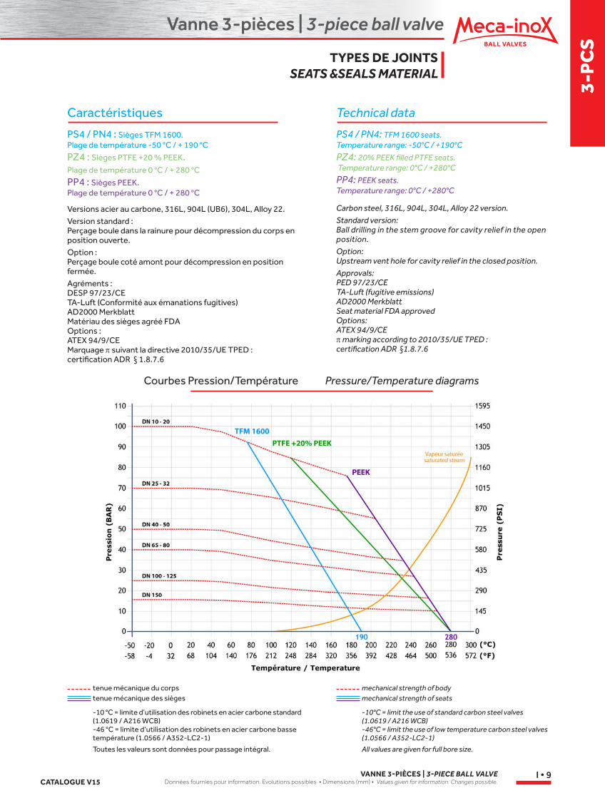
Caractéristiques
PS4 / PN4 : Sièges TFM 1600. Plage de température -50 °C / + 190 °C
PZ4 : Sièges PTFE +20 % PEEK. Plage de température 0 °C / + 280 °C
PP4 : Sièges PEEK. Plage de température 0 °C / + 280 °C
Versions acier au carbone, 316L, 904L (UB6), 304L, Alloy 22.Version standard : Perçage boule dans la rainure pour décompression du corps en position ouverte. Option : Perçage boule coté amont pour décompression en position fermée.Agréments : DESP 97/23/CE TA-Luft (Conformité aux émanations fugitives) AD2000 Merkblatt Matériau des sièges agréé FDA Options : ATEX 94/9/CE Marquage p suivant la directive 2010/35/UE TPED : certification ADR § 1.8.7.6
tenue mécanique du corps
-10 °C = limite d’utilisation des robinets en acier carbone standard (1.0619 / A216 WCB)-46 °C = limite d’utilisation des robinets en acier carbone basse température (1.0566 / A352-LC2-1)
-10°C = limit the use of standard carbon steel valves (1.0619 / A216 WCB)-46°C = limit the use of low temperature carbon steel valves (1.0566 / A352-LC2-1)
mechanical strength of bodytenue mécanique des sièges mechanical strength of seats
Courbes Pression/Température
Technical data
PS4 / PN4: TFM 1600 seats. Temperature range: -50°C / +190°C
PZ4: 20% PEEK filled PTFE seats. Temperature range: 0°C / +280°C
PP4: PEEK seats. Temperature range: 0°C / +280°C
Carbon steel, 316L, 904L, 304L, Alloy 22 version.Standard version: Ball drilling in the stem groove for cavity relief in the open position. Option: Upstream vent hole for cavity relief in the closed position.Approvals: PED 97/23/CE TA-Luft (fugitive emissions) AD2000 Merkblatt Seat material FDA approved Options: ATEX 94/9/CE p marking according to 2010/35/UE TPED : certification ADR §1.8.7.6
Pressure/Temperature diagrams
Toutes les valeurs sont données pour passage intégral. All values are given for full bore size.
TYPES DE JOINTSSEATS &SEALS MATERIAL
Vanne 3-pièces | 3-piece ball valve
VANNE 3-PIÈCES | 3-PIECE BALL VALVEDonnées fournies pour information. Evolutions possibles • Dimensions (mm) • Values given for information. Changes possible. CATALOGUE V15
I • 10
Caractéristiques
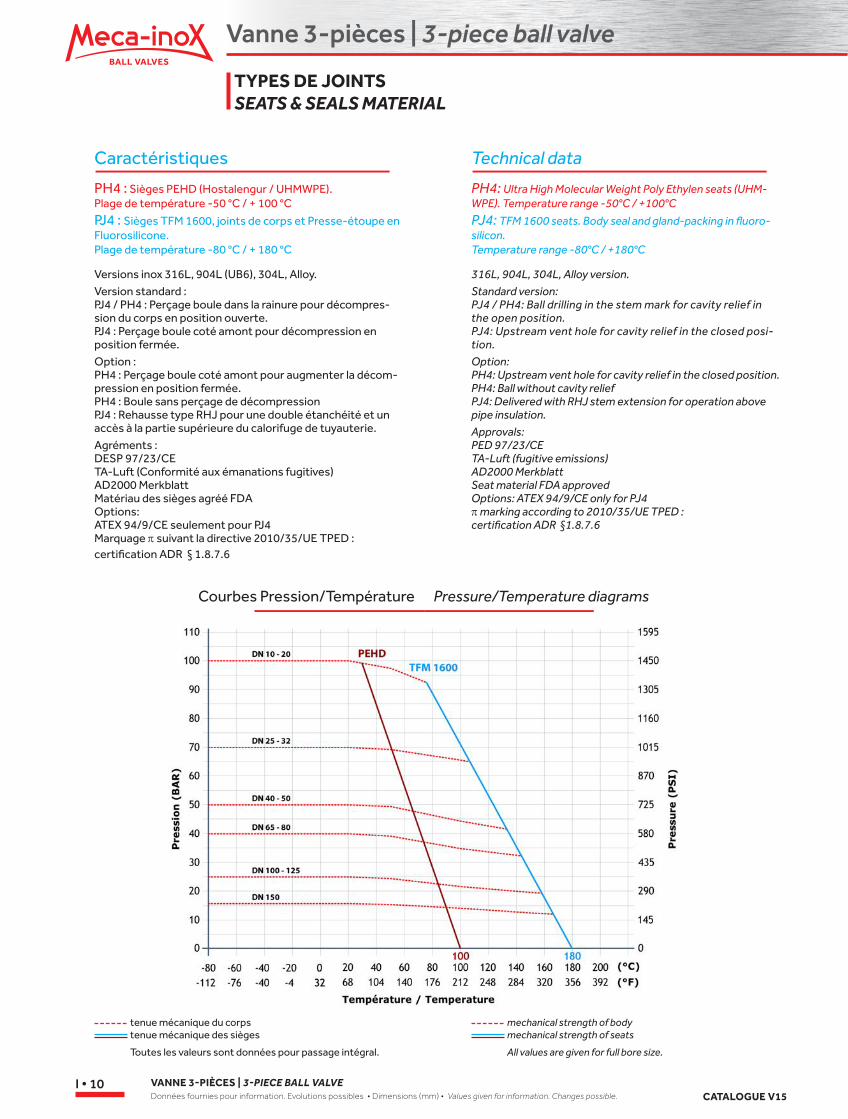
PH4 : Sièges PEHD (Hostalengur / UHMWPE). Plage de température -50 °C / + 100 °C
PJ4 : Sièges TFM 1600, joints de corps et Presse-étoupe en Fluorosilicone. Plage de température -80 °C / + 180 °C
Versions inox 316L, 904L (UB6), 304L, Alloy.Version standard : PJ4 / PH4 : Perçage boule dans la rainure pour décompres-sion du corps en position ouverte. PJ4 : Perçage boule coté amont pour décompression en position fermée. Option : PH4 : Perçage boule coté amont pour augmenter la décom-pression en position fermée.PH4 : Boule sans perçage de décompressionPJ4 : Rehausse type RHJ pour une double étanchéité et un accès à la partie supérieure du calorifuge de tuyauterie.Agréments : DESP 97/23/CE TA-Luft (Conformité aux émanations fugitives) AD2000 Merkblatt Matériau des sièges agréé FDA Options: ATEX 94/9/CE seulement pour PJ4 Marquage p suivant la directive 2010/35/UE TPED : certification ADR § 1.8.7.6
tenue mécanique du corps mechanical strength of bodytenue mécanique des sièges mechanical strength of seats
Technical data
PH4: Ultra High Molecular Weight Poly Ethylen seats (UHM-WPE). Temperature range -50°C / +100°C
PJ4: TFM 1600 seats. Body seal and gland-packing in fluoro-silicon. Temperature range -80°C / +180°C
316L, 904L, 304L, Alloy version.Standard version: PJ4 / PH4: Ball drilling in the stem mark for cavity relief in the open position. PJ4: Upstream vent hole for cavity relief in the closed posi-tion. Option: PH4: Upstream vent hole for cavity relief in the closed position.PH4: Ball without cavity reliefPJ4: Delivered with RHJ stem extension for operation above pipe insulation.Approvals: PED 97/23/CE TA-Luft (fugitive emissions) AD2000 Merkblatt Seat material FDA approved Options: ATEX 94/9/CE only for PJ4 p marking according to 2010/35/UE TPED : certification ADR §1.8.7.6
Courbes Pression/Température Pressure/Temperature diagrams
Toutes les valeurs sont données pour passage intégral. All values are given for full bore size.
TYPES DE JOINTSSEATS & SEALS MATERIAL
Vanne 3-pièces | 3-piece ball valve
3-P
CS
CATALOGUE V15VANNE 3-PIÈCES | 3-PIECE BALL VALVE
Données fournies pour information. Evolutions possibles • Dimensions (mm) • Values given for information. Changes possible.I • 11
Caractéristiques
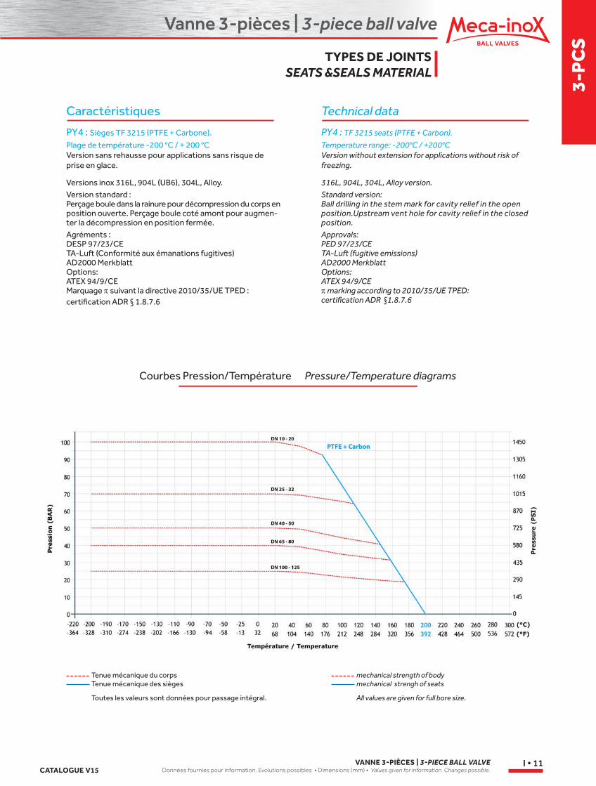
PY4 : Sièges TF 3215 (PTFE + Carbone).
Plage de température -200 °C / + 200 °CVersion sans rehausse pour applications sans risque de prise en glace.
Versions inox 316L, 904L (UB6), 304L, Alloy.Version standard : Perçage boule dans la rainure pour décompression du corps en position ouverte. Perçage boule coté amont pour augmen-ter la décompression en position fermée.Agréments : DESP 97/23/CE TA-Luft (Conformité aux émanations fugitives) AD2000 Merkblatt Options: ATEX 94/9/CE Marquage p suivant la directive 2010/35/UE TPED : certification ADR § 1.8.7.6
Tenue mécanique du corps
Toutes les valeurs sont données pour passage intégral. All values are given for full bore size.
mechanical strength of bodyTenue mécanique des sièges mechanical strengh of seats
Courbes Pression/Température
Technical data
PY4 : TF 3215 seats (PTFE + Carbon).
Temperature range: -200°C / +200°C Version without extension for applications without risk of freezing.
316L, 904L, 304L, Alloy version.Standard version: Ball drilling in the stem mark for cavity relief in the open position.Upstream vent hole for cavity relief in the closed position.Approvals: PED 97/23/CE TA-Luft (fugitive emissions) AD2000 Merkblatt Options: ATEX 94/9/CE p marking according to 2010/35/UE TPED: certification ADR §1.8.7.6
Pressure/Temperature diagrams
TYPES DE JOINTSSEATS &SEALS MATERIAL
Vanne 3-pièces | 3-piece ball valve
VANNE 3-PIÈCES | 3-PIECE BALL VALVEDonnées fournies pour information. Evolutions possibles • Dimensions (mm) • Values given for information. Changes possible. CATALOGUE V15
I • 12
DN 10 à 50 | Size 1/4’’ to 2’’ DN 65 à 200 | Size 2’’1/2 to 8’’
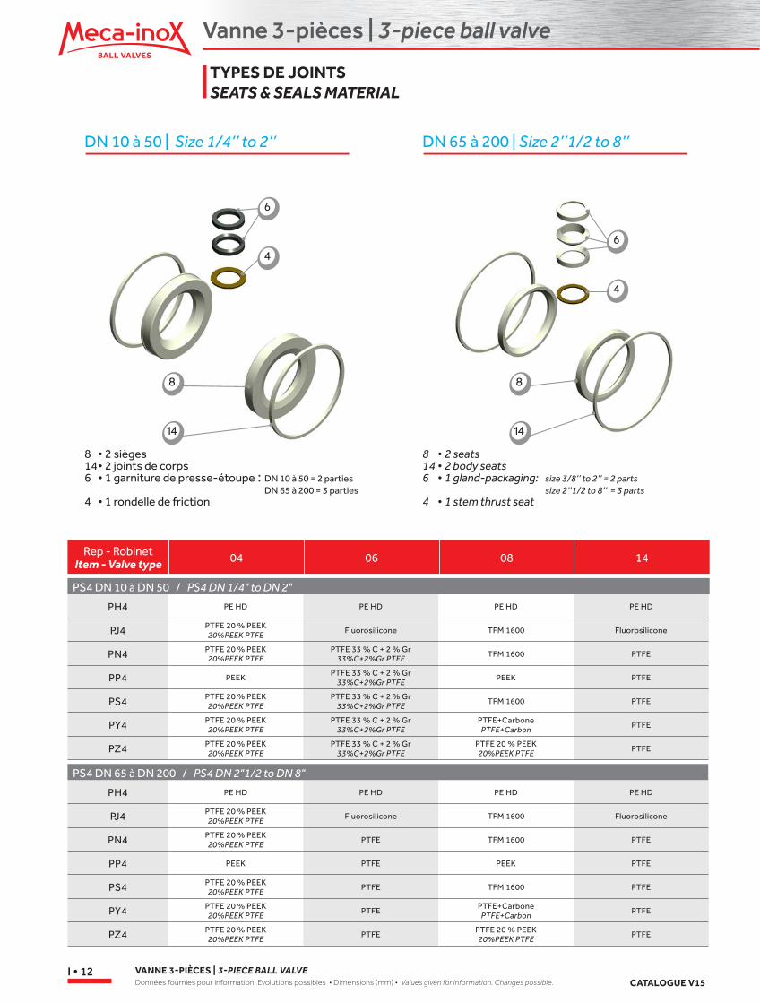
8 • 2 sièges14 • 2 joints de corps6 • 1 garniture de presse-étoupe : DN 10 à 50 = 2 parties DN 65 à 200 = 3 parties4 • 1 rondelle de friction
8 • 2 seats14 • 2 body seats6 • 1 gland-packaging: size 3/8’’ to 2’’ = 2 parts size 2’’1/2 to 8’’ = 3 parts4 • 1 stem thrust seat
Rep - RobinetItem - Valve type 14080604
PH4 PE HD PE HD PE HD PE HD
PJ4 PTFE 20 % PEEK 20%PEEK PTFE Fluorosilicone TFM 1600 Fluorosilicone
PN4 PTFE 20 % PEEK 20%PEEK PTFE
PTFE 33 % C + 2 % Gr 33%C+2%Gr PTFE
TFM 1600 PTFE
PP4 PEEK PTFE 33 % C + 2 % Gr 33%C+2%Gr PTFE PEEK PTFE
PS4 PTFE 20 % PEEK 20%PEEK PTFE
PTFE 33 % C + 2 % Gr 33%C+2%Gr PTFE TFM 1600 PTFE
PY4 PTFE 20 % PEEK 20%PEEK PTFE
PTFE 33 % C + 2 % Gr 33%C+2%Gr PTFE
PTFE+Carbone PTFE+Carbon PTFE
PZ4 PTFE 20 % PEEK 20%PEEK PTFE
PTFE 33 % C + 2 % Gr 33%C+2%Gr PTFE
PTFE 20 % PEEK 20%PEEK PTFE PTFE
PS4 DN 10 à DN 50 / PS4 DN 1/4" to DN 2"
PH4 PE HD PE HD PE HD PE HD
PJ4 PTFE 20 % PEEK 20%PEEK PTFE Fluorosilicone TFM 1600 Fluorosilicone
PN4 PTFE 20 % PEEK 20%PEEK PTFE PTFE TFM 1600 PTFE
PP4 PEEK PTFE PEEK PTFE
PS4 PTFE 20 % PEEK 20%PEEK PTFE PTFE TFM 1600 PTFE
PY4 PTFE 20 % PEEK 20%PEEK PTFE PTFE PTFE+Carbone
PTFE+Carbon PTFE
PZ4 PTFE 20 % PEEK 20%PEEK PTFE PTFE PTFE 20 % PEEK
20%PEEK PTFE PTFE
PS4 DN 65 à DN 200 / PS4 DN 2"1/2 to DN 8"
TYPES DE JOINTSSEATS & SEALS MATERIAL
6
4
8
14
6
4
8
14
Vanne 3-pièces | 3-piece ball valve
3-P
CS
CATALOGUE V15VANNE 3-PIÈCES | 3-PIECE BALL VALVE
Données fournies pour information. Evolutions possibles • Dimensions (mm) • Values given for information. Changes possible.I • 13
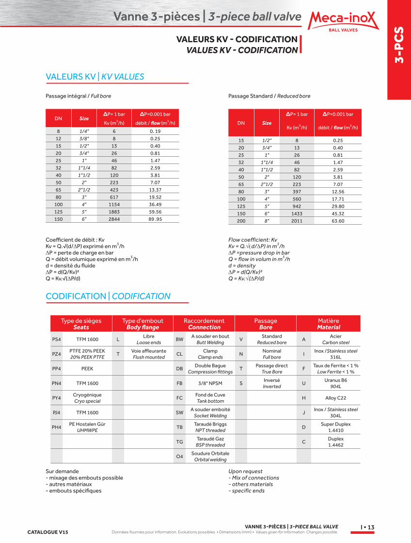
VALEURS KV | KV VALUES
CODIFICATION | CODIFICATION
Type de sièges Seats
Type d'embout Body flange
Raccordement Connection
Passage Bore
Matière Material
PS4 TFM 1600 LLibre
Loose endsBW
A souder en bout Butt Welding
VStandard
Reduced boreA
Acier Carbon steel
PZ4PTFE 20% PEEK 20% PEEK PTFE
TVoie affleurante Flush mounted
CLClamp
Clamp endsN
Nominal Full bore
IInox /Stainless steel
316L
PP4 PEEK DBDouble Bague
Compression fittingsT
Passage direct True Bore
FTaux de Ferrite < 1 %
Low Ferrite < 1 %
PN4 TFM 1600 FB 3/8" NPSM SInversé
InvertedU
Uranus B6 904L
PY4Cryogénique Cryo special
FCFond de Cuve Tank bottom
H Alloy C22
PJ4 TFM 1600 SWA souder emboité
Socket WeldingJ
Inox / Stainless steel 304L
PH4PE Hostalen Gür
UHMWPETB
Taraudé Briggs NPT threaded
DSuper Duplex
1.4410
TGTaraudé Gaz
BSP threadedC
Duplex 1.4462
O4Soudure Orbitale
Orbital welding
DN Size∆P= 1 bar ∆P=0.001 bar
Kv (m3/h) débit / flow (m3/h)
8 1/4" 6 0. 1912 3/8" 8 0.2515 1/2" 13 0.4020 3/4" 26 0.8125 1" 46 1.4732 1"1/4 82 2.5940 1"1/2 120 3.8150 2" 223 7.0765 2"1/2 423 13.3780 3" 617 19.52
100 4" 1154 36.49125 5" 1883 59.56150 6" 2844 89 .95
DN Size
∆P= 1 bar ∆P=0.001 bar
Kv (m3/h) débit / flow (m3/h)
15 1/2" 8 0.2520 3/4" 13 0.4025 1" 26 0.8132 1"1/4 46 1.4740 1"1/2 82 2.5950 2" 120 3.8165 2"1/2 223 7.0780 3" 397 12.56
100 4" 560 17.71125 5" 942 29.80150 6" 1433 45.32200 8" 2011 63.60
Coefficient de débit : KvKv = Q.√(d/∆P) exprimé en m3/h∆P = perte de charge en barQ = débit volumique exprimé en m3/hd = densité du fluide∆P = d(Q/Kv)²Q = Kv.√(∆P/d)
Passage intégral / Full bore Passage Standard / Reduced bore
Sur demande- mixage des embouts possible- autres matériaux- embouts spécifiques
Flow coefficient: KvKv = Q.√(d/∆P) in m3/h∆P =pressure drop in barQ = flow in volum in m3/hd = density∆P = d(Q/Kv)²Q = Kv.√(∆P/d)
Upon request- Mix of connections- others materials- specific ends
VALEURS KV - CODIFICATIONVALUES KV - CODIFICATION
Vanne 3-pièces | 3-piece ball valve
VANNE 3-PIÈCES | 3-PIECE BALL VALVEDonnées fournies pour information. Evolutions possibles • Dimensions (mm) • Values given for information. Changes possible. CATALOGUE V15
I • 14
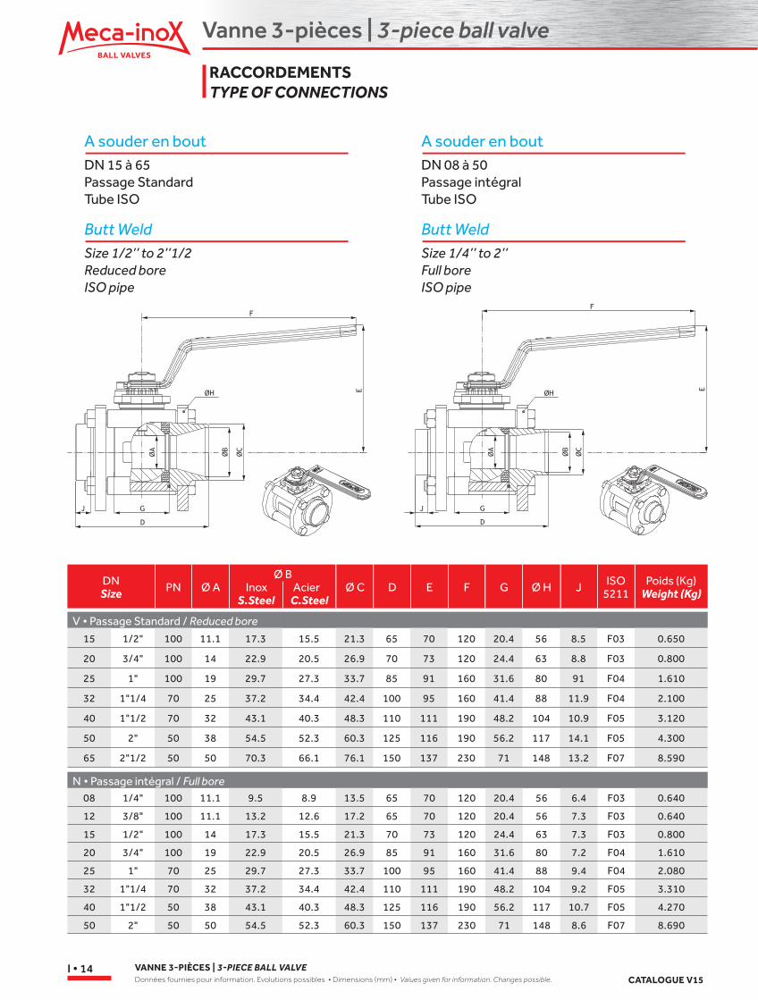
A souder en boutDN 15 à 65Passage StandardTube ISO
Butt Weld Size 1/2’’ to 2’’1/2Reduced boreISO pipe
A souder en boutDN 08 à 50Passage intégralTube ISO
Butt WeldSize 1/4’’ to 2’’Full boreISO pipe
DNSize PN Ø A
Ø BInox Acier
S.Steel C.SteelØ C D E F G Ø H J ISO
5211Poids (Kg)
Weight (Kg)
V • Passage Standard / Reduced bore
N • Passage intégral / Full bore08 1/4" 100 11.1 9.5 8.9 13.5 65 70 120 20.4 56 6.4 F03 0.640
12 3/8" 100 11.1 13.2 12.6 17.2 65 70 120 20.4 56 7.3 F03 0.640
15 1/2" 100 14 17.3 15.5 21.3 70 73 120 24.4 63 7.3 F03 0.800
20 3/4" 100 19 22.9 20.5 26.9 85 91 160 31.6 80 7.2 F04 1.610
25 1" 70 25 29.7 27.3 33.7 100 95 160 41.4 88 9.4 F04 2.080
32 1"1/4 70 32 37.2 34.4 42.4 110 111 190 48.2 104 9.2 F05 3.310
40 1"1/2 50 38 43.1 40.3 48.3 125 116 190 56.2 117 10.7 F05 4.270
50 2" 50 50 54.5 52.3 60.3 150 137 230 71 148 8.6 F07 8.690
15 1/2" 100 11.1 17.3 15.5 21.3 65 70 120 20.4 56 8.5 F03 0.650
20 3/4" 100 14 22.9 20.5 26.9 70 73 120 24.4 63 8.8 F03 0.800
25 1" 100 19 29.7 27.3 33.7 85 91 160 31.6 80 91 F04 1.610
32 1"1/4 70 25 37.2 34.4 42.4 100 95 160 41.4 88 11.9 F04 2.100
40 1"1/2 70 32 43.1 40.3 48.3 110 111 190 48.2 104 10.9 F05 3.120
50 2" 50 38 54.5 52.3 60.3 125 116 190 56.2 117 14.1 F05 4.300
65 2"1/2 50 50 70.3 66.1 76.1 150 137 230 71 148 13.2 F07 8.590
RACCORDEMENTS TYPE OF CONNECTIONS
Vanne 3-pièces | 3-piece ball valve
3-P
CS
CATALOGUE V15VANNE 3-PIÈCES | 3-PIECE BALL VALVE
Données fournies pour information. Evolutions possibles • Dimensions (mm) • Values given for information. Changes possible.I • 15
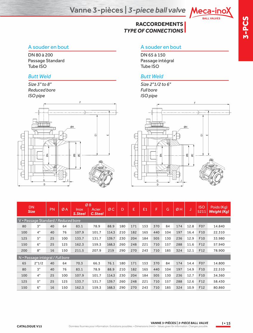
A souder en boutDN 80 à 200Passage StandardTube ISO
Butt WeldSize 3" to 8"Reduced boreISO pipe
A souder en boutDN 65 à 150Passage intégralTube ISO
Butt WeldSize 2"1/2 to 6"Full boreISO pipe
DNSize PN Ø A
Ø BInox Acier
S.Steel C.SteelØ C D E E1 F G Ø H J ISO
5211Poids (Kg)
Weight (Kg)
V • Passage Standard / Reduced bore
N • Passage intégral / Full bore65 2"1/2 40 64 70.3 66.3 76.1 180 171 153 370 84 174 14.4 F07 14.800
80 3" 40 76 83.1 78.9 88.9 210 182 165 440 104 197 14.9 F10 22.510
100 4" 25 100 107.9 101.7 114.3 230 204 184 505 130 236 12.7 F10 34.360
125 5" 25 125 133.7 131.7 139.7 260 248 221 710 157 288 12.6 F12 58.430
150 6" 16 150 162.3 159.3 168.3 290 270 243 710 185 324 10.9 F12 80.860
80 3" 40 64 83.1 78.9 88.9 180 171 153 370 84 174 12.8 F07 14.840
100 4" 40 76 107.9 101.7 114.3 210 182 165 440 104 197 16.4 F10 22.310
125 5" 25 100 133.7 131.7 139.7 230 204 184 505 130 236 12.9 F10 33.980
150 6" 25 125 162.3 159.3 168.3 260 248 221 710 157 288 11.6 F12 57.940
200 8" 16 150 211.5 207.9 219 290 270 243 710 185 324 12.1 F12 78.900
RACCORDEMENTSTYPE OF CONNECTIONS
Vanne 3-pièces | 3-piece ball valve
VANNE 3-PIÈCES | 3-PIECE BALL VALVEDonnées fournies pour information. Evolutions possibles • Dimensions (mm) • Values given for information. Changes possible. CATALOGUE V15
I • 16
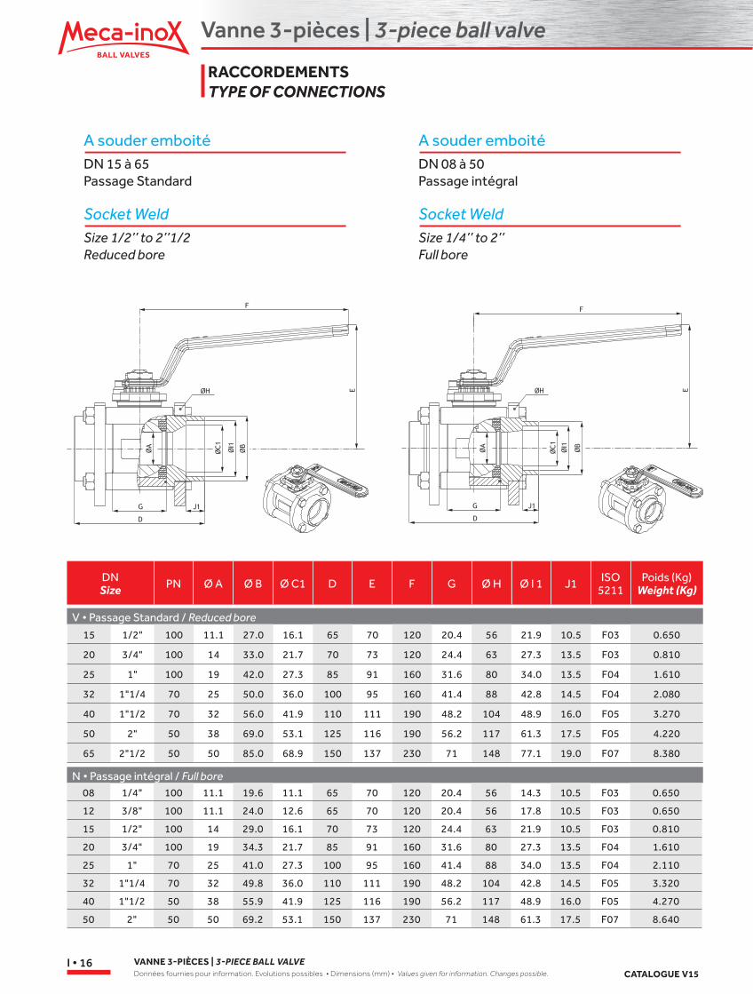
A souder emboitéDN 15 à 65Passage Standard
Socket WeldSize 1/2’’ to 2’’1/2Reduced bore
A souder emboitéDN 08 à 50Passage intégral
Socket WeldSize 1/4’’ to 2’’Full bore
DNSize PN Ø A Ø B Ø C1 D E F G Ø H Ø I 1 J1 ISO
5211Poids (Kg)
Weight (Kg)
V • Passage Standard / Reduced bore
N • Passage intégral / Full bore08 1/4" 100 11.1 19.6 11.1 65 70 120 20.4 56 14.3 10.5 F03 0.650
12 3/8" 100 11.1 24.0 12.6 65 70 120 20.4 56 17.8 10.5 F03 0.650
15 1/2" 100 14 29.0 16.1 70 73 120 24.4 63 21.9 10.5 F03 0.810
20 3/4" 100 19 34.3 21.7 85 91 160 31.6 80 27.3 13.5 F04 1.610
25 1" 70 25 41.0 27.3 100 95 160 41.4 88 34.0 13.5 F04 2.110
32 1"1/4 70 32 49.8 36.0 110 111 190 48.2 104 42.8 14.5 F05 3.320
40 1"1/2 50 38 55.9 41.9 125 116 190 56.2 117 48.9 16.0 F05 4.270
50 2" 50 50 69.2 53.1 150 137 230 71 148 61.3 17.5 F07 8.640
15 1/2" 100 11.1 27.0 16.1 65 70 120 20.4 56 21.9 10.5 F03 0.650
20 3/4" 100 14 33.0 21.7 70 73 120 24.4 63 27.3 13.5 F03 0.810
25 1" 100 19 42.0 27.3 85 91 160 31.6 80 34.0 13.5 F04 1.610
32 1"1/4 70 25 50.0 36.0 100 95 160 41.4 88 42.8 14.5 F04 2.080
40 1"1/2 70 32 56.0 41.9 110 111 190 48.2 104 48.9 16.0 F05 3.270
50 2" 50 38 69.0 53.1 125 116 190 56.2 117 61.3 17.5 F05 4.220
65 2"1/2 50 50 85.0 68.9 150 137 230 71 148 77.1 19.0 F07 8.380
RACCORDEMENTSTYPE OF CONNECTIONS
Vanne 3-pièces | 3-piece ball valve
3-P
CS
CATALOGUE V15VANNE 3-PIÈCES | 3-PIECE BALL VALVE
Données fournies pour information. Evolutions possibles • Dimensions (mm) • Values given for information. Changes possible.I • 17
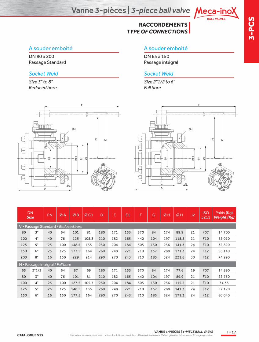
A souder emboitéDN 80 à 200Passage Standard
Socket WeldSize 3" to 8"Reduced bore
A souder emboitéDN 65 à 150Passage intégral
Socket WeldSize 2"1/2 to 6"Full bore
DNSize PN Ø A Ø B Ø C1 D E E1 F G Ø H Ø I1 J2 ISO
5211Poids (Kg)
Weight (Kg)
V • Passage Standard / Reduced bore
N • Passage intégral / Full bore65 2"1/2 40 64 87 69 180 171 153 370 84 174 77.6 19 F07 14.890
80 3" 40 76 101 81 210 182 165 440 104 197 89.9 21 F10 22.750
100 4" 25 100 127.5 105.3 230 204 184 505 130 236 115.5 21 F10 34.35
125 5" 25 125 148.5 135 260 248 221 710 157 288 141.3 24 F12 57.120
150 6" 16 150 177.5 164 290 270 243 710 185 324 171.3 24 F12 80.040
80 3" 40 64 101 81 180 171 153 370 84 174 89.9 21 F07 14.700
100 4" 40 76 125 105.3 210 182 165 440 104 197 115.5 21 F10 22.010
125 5" 25 100 148.5 135 230 204 184 505 130 236 141.3 24 F10 32.820
150 6" 25 125 177.5 164 260 248 221 710 157 288 171.3 24 F12 56.140
200 8" 16 150 229 214 290 270 243 710 185 324 221.8 30 F12 74.290
RACCORDEMENTSTYPE OF CONNECTIONS
Vanne 3-pièces | 3-piece ball valve
VANNE 3-PIÈCES | 3-PIECE BALL VALVEDonnées fournies pour information. Evolutions possibles • Dimensions (mm) • Values given for information. Changes possible. CATALOGUE V15
I • 18
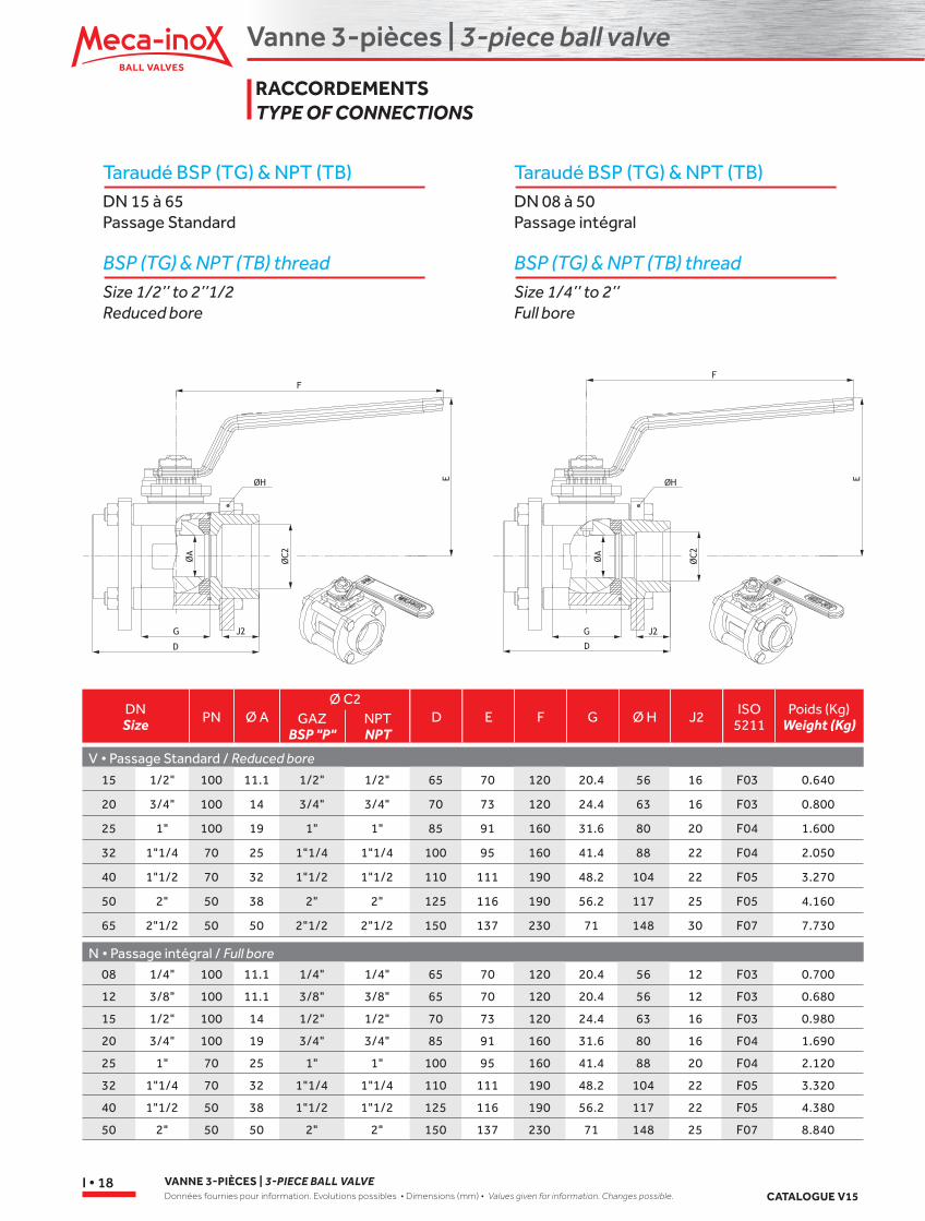
Taraudé BSP (TG) & NPT (TB)DN 15 à 65Passage Standard
BSP (TG) & NPT (TB) thread Size 1/2’’ to 2’’1/2Reduced bore
Taraudé BSP (TG) & NPT (TB)DN 08 à 50Passage intégral
BSP (TG) & NPT (TB) thread Size 1/4’’ to 2’’Full bore
DNSize PN Ø A
Ø C2D E F G Ø H J2 ISO
5211Poids (Kg)
Weight (Kg)
V • Passage Standard / Reduced bore
N • Passage intégral / Full bore
15 1/2" 100 11.1 1/2" 1/2" 65 70 120 20.4 56 16 F03 0.640
20 3/4" 100 14 3/4" 3/4" 70 73 120 24.4 63 16 F03 0.800
25 1" 100 19 1" 1" 85 91 160 31.6 80 20 F04 1.600
32 1"1/4 70 25 1"1/4 1"1/4 100 95 160 41.4 88 22 F04 2.050
40 1"1/2 70 32 1"1/2 1"1/2 110 111 190 48.2 104 22 F05 3.270
50 2" 50 38 2" 2" 125 116 190 56.2 117 25 F05 4.160
65 2"1/2 50 50 2"1/2 2"1/2 150 137 230 71 148 30 F07 7.730
GAZBSP "P"
NPTNPT
08 1/4" 100 11.1 1/4" 1/4" 65 70 120 20.4 56 12 F03 0.700
12 3/8" 100 11.1 3/8" 3/8" 65 70 120 20.4 56 12 F03 0.680
15 1/2" 100 14 1/2" 1/2" 70 73 120 24.4 63 16 F03 0.980
20 3/4" 100 19 3/4" 3/4" 85 91 160 31.6 80 16 F04 1.690
25 1" 70 25 1" 1" 100 95 160 41.4 88 20 F04 2.120
32 1"1/4 70 32 1"1/4 1"1/4 110 111 190 48.2 104 22 F05 3.320
40 1"1/2 50 38 1"1/2 1"1/2 125 116 190 56.2 117 22 F05 4.380
50 2" 50 50 2" 2" 150 137 230 71 148 25 F07 8.840
RACCORDEMENTSTYPE OF CONNECTIONS
Vanne 3-pièces | 3-piece ball valve
3-P
CS
CATALOGUE V15VANNE 3-PIÈCES | 3-PIECE BALL VALVE
Données fournies pour information. Evolutions possibles • Dimensions (mm) • Values given for information. Changes possible.I • 19
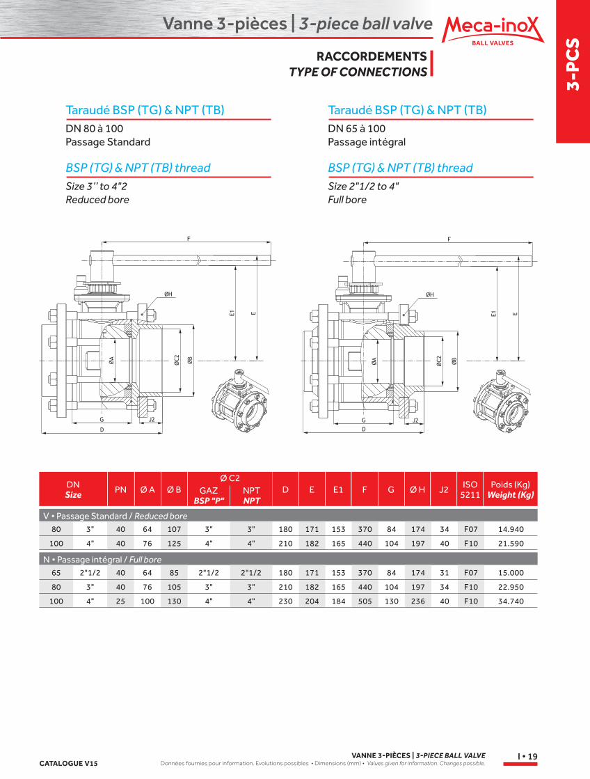
Taraudé BSP (TG) & NPT (TB)DN 80 à 100Passage Standard
BSP (TG) & NPT (TB) thread Size 3’’ to 4"2Reduced bore
Taraudé BSP (TG) & NPT (TB)DN 65 à 100Passage intégral
BSP (TG) & NPT (TB) thread Size 2"1/2 to 4"Full bore
DNSize PN Ø A Ø B D E E1 F G Ø H J2 ISO
5211Poids (Kg)
Weight (Kg)
V • Passage Standard / Reduced bore
N • Passage intégral / Full bore65 2"1/2 40 64 85 2"1/2 2"1/2 180 171 153 370 84 174 31 F07 15.000
80 3" 40 76 105 3" 3" 210 182 165 440 104 197 34 F10 22.950
100 4" 25 100 130 4" 4" 230 204 184 505 130 236 40 F10 34.740
80 3" 40 64 107 3" 3" 180 171 153 370 84 174 34 F07 14.940
100 4" 40 76 125 4" 4" 210 182 165 440 104 197 40 F10 21.590
Ø C2GAZ
BSP "P"NPTNPT
RACCORDEMENTSTYPE OF CONNECTIONS
Vanne 3-pièces | 3-piece ball valve
VANNE 3-PIÈCES | 3-PIECE BALL VALVEDonnées fournies pour information. Evolutions possibles • Dimensions (mm) • Values given for information. Changes possible. CATALOGUE V15
I • 20
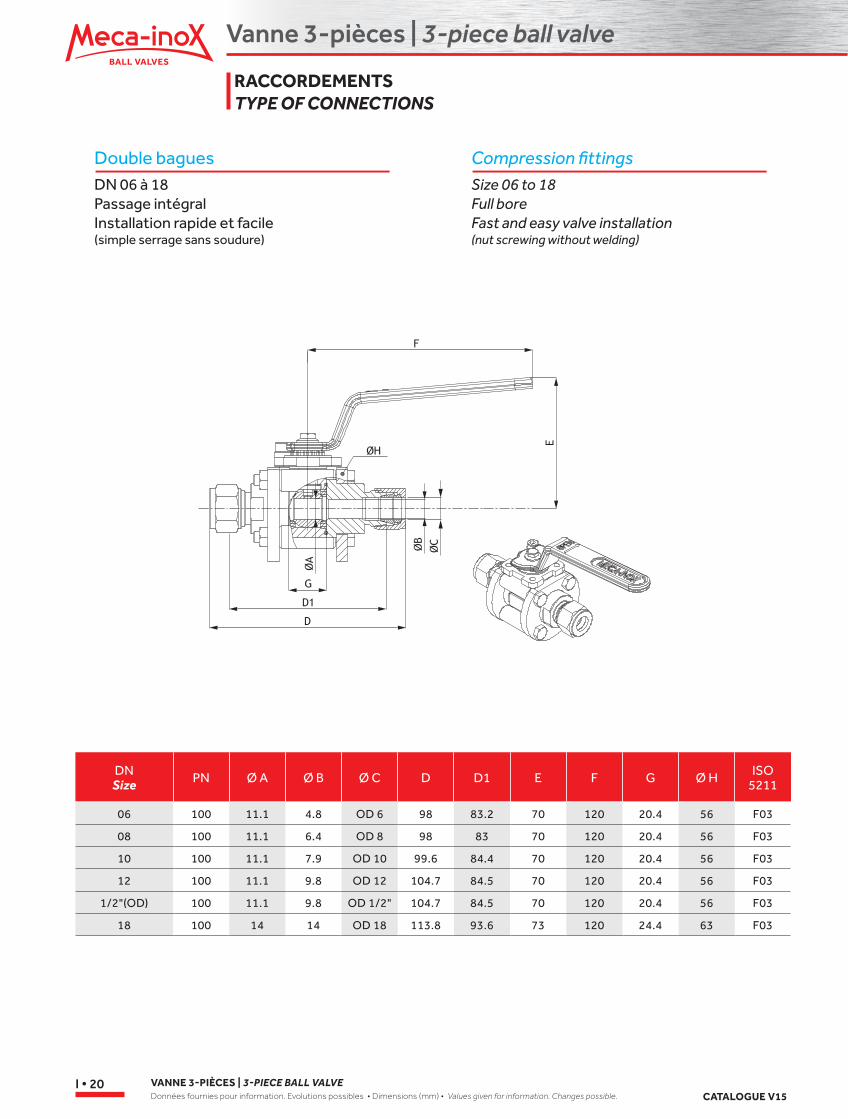
Double baguesDN 06 à 18Passage intégralInstallation rapide et facile(simple serrage sans soudure)
Compression fittingsSize 06 to 18Full boreFast and easy valve installation(nut screwing without welding)
DNSize PN Ø A Ø B Ø C D D1 E F G Ø H ISO
5211
06 100 11.1 4.8 OD 6 98 83.2 70 120 20.4 56 F03
08 100 11.1 6.4 OD 8 98 83 70 120 20.4 56 F03
10 100 11.1 7.9 OD 10 99.6 84.4 70 120 20.4 56 F03
12 100 11.1 9.8 OD 12 104.7 84.5 70 120 20.4 56 F03
1/2"(OD) 100 11.1 9.8 OD 1/2" 104.7 84.5 70 120 20.4 56 F03
18 100 14 14 OD 18 113.8 93.6 73 120 24.4 63 F03
RACCORDEMENTSTYPE OF CONNECTIONS
Vanne 3-pièces | 3-piece ball valve
3-P
CS
CATALOGUE V15VANNE 3-PIÈCES | 3-PIECE BALL VALVE
Données fournies pour information. Evolutions possibles • Dimensions (mm) • Values given for information. Changes possible.I • 21
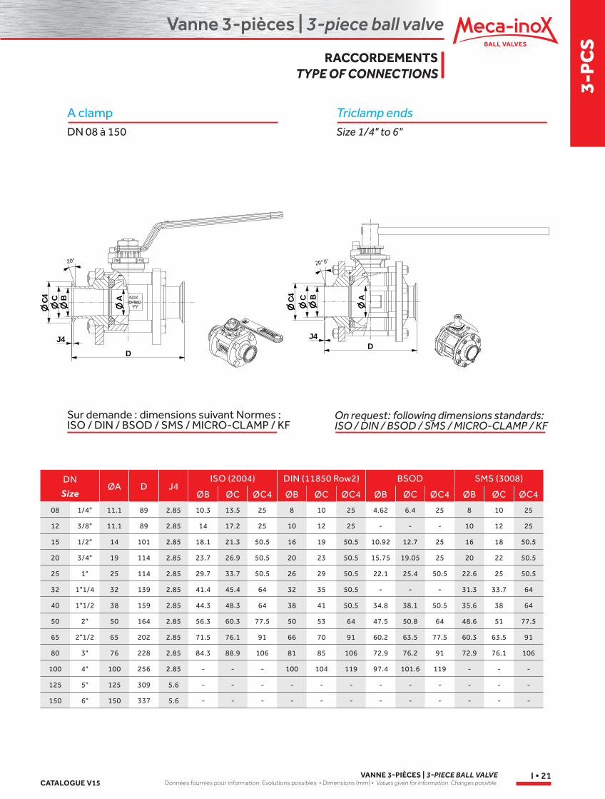
Triclamp endsSize 1/4" to 6"
On request: following dimensions standards:ISO / DIN / BSOD / SMS / MICRO-CLAMP / KF
A clampDN 08 à 150
DN
SizeØA D J4
ISO (2004) DIN (11850 Row2) BSOD SMS (3008)
ØB ØC ØC4 ØB ØC ØC4 ØB ØC ØC4 ØB ØC ØC4
08 1/4" 11.1 89 2.85 10.3 13.5 25 8 10 25 4.62 6.4 25 8 10 25
12 3/8" 11.1 89 2.85 14 17.2 25 10 12 25 - - - 10 12 25
15 1/2" 14 101 2.85 18.1 21.3 50.5 16 19 50.5 10.92 12.7 25 16 18 50.5
20 3/4" 19 114 2.85 23.7 26.9 50.5 20 23 50.5 15.75 19.05 25 20 22 50.5
25 1" 25 114 2.85 29.7 33.7 50.5 26 29 50.5 22.1 25.4 50.5 22.6 25 50.5
32 1"1/4 32 139 2.85 41.4 45.4 64 32 35 50.5 - - - 31.3 33.7 64
40 1"1/2 38 159 2.85 44.3 48.3 64 38 41 50.5 34.8 38.1 50.5 35.6 38 64
50 2" 50 164 2.85 56.3 60.3 77.5 50 53 64 47.5 50.8 64 48.6 51 77.5
65 2"1/2 65 202 2.85 71.5 76.1 91 66 70 91 60.2 63.5 77.5 60.3 63.5 91
80 3" 76 228 2.85 84.3 88.9 106 81 85 106 72.9 76.2 91 72.9 76.1 106
100 4" 100 256 2.85 - - - 100 104 119 97.4 101.6 119 - - -
125 5" 125 309 5.6 - - - - - - - - - - - -
150 6" 150 337 5.6 - - - - - - - - - - - -
Sur demande : dimensions suivant Normes :ISO / DIN / BSOD / SMS / MICRO-CLAMP / KF
D
C B AC4
J4
20°0'
A
D
C4 C B
20°
J4
RACCORDEMENTSTYPE OF CONNECTIONS
Vanne 3-pièces | 3-piece ball valve
VANNE 3-PIÈCES | 3-PIECE BALL VALVEDonnées fournies pour information. Evolutions possibles • Dimensions (mm) • Values given for information. Changes possible. CATALOGUE V15
I • 22
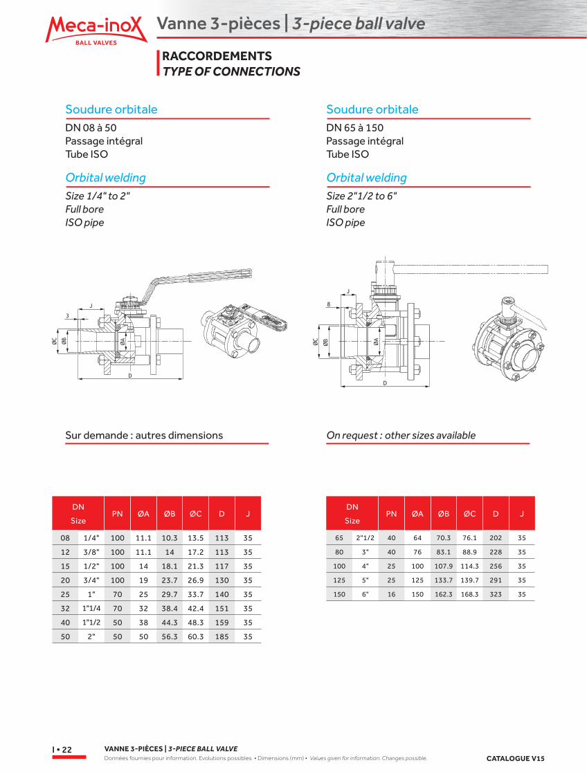
Soudure orbitaleDN 08 à 50Passage intégralTube ISO
Orbital weldingSize 1/4" to 2"Full boreISO pipe
Soudure orbitaleDN 65 à 150Passage intégralTube ISO
Orbital weldingSize 2"1/2 to 6"Full boreISO pipe
Sur demande : autres dimensions On request : other sizes available
DN
SizePN ØA ØB ØC D J
08 1/4" 100 11.1 10.3 13.5 113 35
12 3/8" 100 11.1 14 17.2 113 35
15 1/2" 100 14 18.1 21.3 117 35
20 3/4" 100 19 23.7 26.9 130 35
25 1" 70 25 29.7 33.7 140 35
32 1"1/4 70 32 38.4 42.4 151 35
40 1"1/2 50 38 44.3 48.3 159 35
50 2" 50 50 56.3 60.3 185 35
DN
SizePN ØA ØB ØC D J
65 2"1/2 40 64 70.3 76.1 202 35
80 3" 40 76 83.1 88.9 228 35
100 4" 25 100 107.9 114.3 256 35
125 5" 25 125 133.7 139.7 291 35
150 6" 16 150 162.3 168.3 323 35
RACCORDEMENTSTYPE OF CONNECTIONS
Vanne 3-pièces | 3-piece ball valve
3-P
CS
CATALOGUE V15VANNE 3-PIÈCES | 3-PIECE BALL VALVE
Données fournies pour information. Evolutions possibles • Dimensions (mm) • Values given for information. Changes possible.I • 23
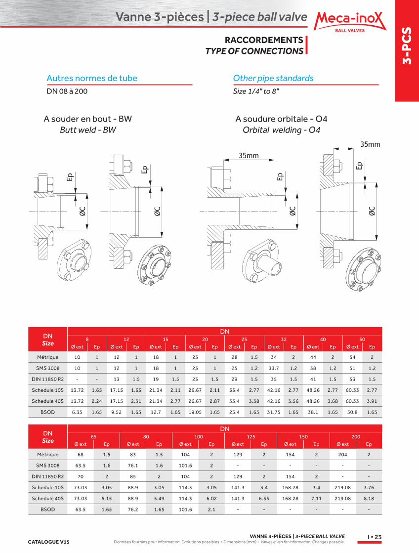
Autres normes de tubeDN 08 à 200
Other pipe standardsSize 1/4" to 8"
DNSize
DN
Métrique 10 1 12 1 18 1 23 1 28 1.5 34 2 44 2 54 2
SMS 3008 10 1 12 1 18 1 23 1 25 1.2 33.7 1.2 38 1.2 51 1.2
DIN 11850 R2 - - 13 1.5 19 1.5 23 1.5 29 1.5 35 1.5 41 1.5 53 1.5
Schedule 10S 13.72 1.65 17.15 1.65 21.34 2.11 26.67 2.11 33.4 2.77 42.16 2.77 48.26 2.77 60.33 2.77
Schedule 40S 13.72 2.24 17.15 2.31 21.34 2.77 26.67 2.87 33.4 3.38 42.16 3.56 48.26 3.68 60.33 3.91
BSOD 6.35 1.65 9.52 1.65 12.7 1.65 19.05 1.65 25.4 1.65 31.75 1.65 38.1 1.65 50.8 1.65
Ø ext Ep Ø ext Ep Ø ext Ep Ø ext Ep Ø ext Ep Ø ext Ep Ø ext Ep Ø ext Ep8 12 15 20 25 32 40 50
DNSize
DN
Métrique 68 1.5 83 1.5 104 2 129 2 154 2 204 2
SMS 3008 63.5 1.6 76.1 1.6 101.6 2 - - - - - -
DIN 11850 R2 70 2 85 2 104 2 129 2 154 2 - -
Schedule 10S 73.03 3.05 88.9 3.05 114.3 3.05 141.3 3.4 168.28 3.4 219.08 3.76
Schedule 40S 73.03 5.15 88.9 5.49 114.3 6.02 141.3 6.55 168.28 7.11 219.08 8.18
BSOD 63.5 1.65 76.2 1.65 101.6 2.1 - - - - - -
Ø ext Ø ext Ø ext Ø ext Ø ext Ø extEp Ep Ep Ep Ep Ep65 80 100 125 150 200
A souder en bout - BWButt weld - BW
A soudure orbitale - O4Orbital welding - O4
RACCORDEMENTSTYPE OF CONNECTIONS
Vanne 3-pièces | 3-piece ball valve
VANNE 3-PIÈCES | 3-PIECE BALL VALVEDonnées fournies pour information. Evolutions possibles • Dimensions (mm) • Values given for information. Changes possible. CATALOGUE V15
I • 24
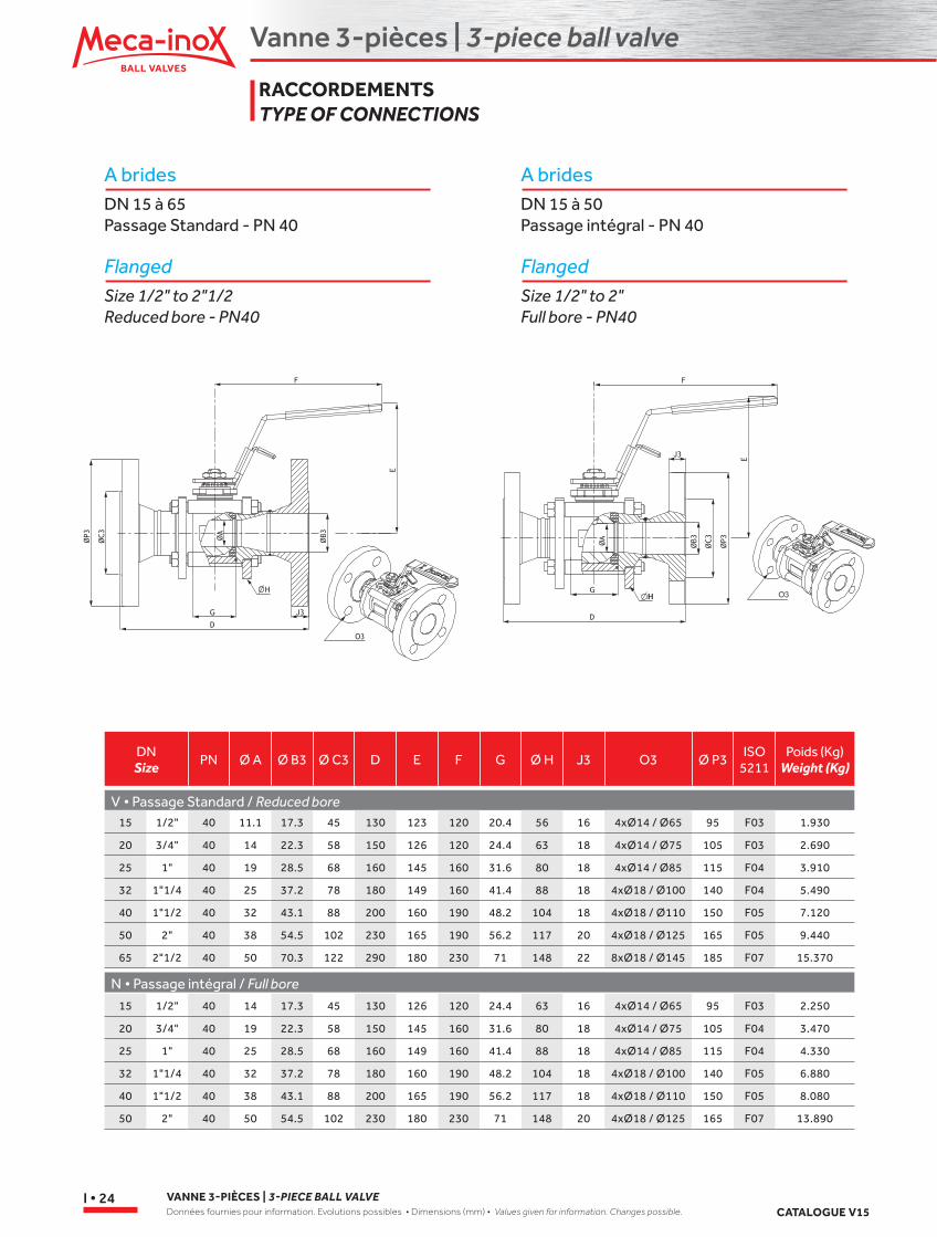
A bridesDN 15 à 65Passage Standard - PN 40
FlangedSize 1/2" to 2"1/2Reduced bore - PN40
A bridesDN 15 à 50Passage intégral - PN 40
FlangedSize 1/2" to 2"Full bore - PN40
DNSize PN Ø A Ø B3 Ø C3 D E F G Ø H J3 O3 Ø P3
ISO5211
Poids (Kg)Weight (Kg)
V • Passage Standard / Reduced bore
N • Passage intégral / Full bore
15 1/2" 40 11.1 17.3 45 130 123 120 20.4 56 16 4xØ14 / Ø65 95 F03 1.930
20 3/4" 40 14 22.3 58 150 126 120 24.4 63 18 4xØ14 / Ø75 105 F03 2.690
25 1" 40 19 28.5 68 160 145 160 31.6 80 18 4xØ14 / Ø85 115 F04 3.910
32 1"1/4 40 25 37.2 78 180 149 160 41.4 88 18 4xØ18 / Ø100 140 F04 5.490
40 1"1/2 40 32 43.1 88 200 160 190 48.2 104 18 4xØ18 / Ø110 150 F05 7.120
50 2" 40 38 54.5 102 230 165 190 56.2 117 20 4xØ18 / Ø125 165 F05 9.440
65 2"1/2 40 50 70.3 122 290 180 230 71 148 22 8xØ18 / Ø145 185 F07 15.370
15 1/2" 40 14 17.3 45 130 126 120 24.4 63 16 4xØ14 / Ø65 95 F03 2.250
20 3/4" 40 19 22.3 58 150 145 160 31.6 80 18 4xØ14 / Ø75 105 F04 3.470
25 1" 40 25 28.5 68 160 149 160 41.4 88 18 4xØ14 / Ø85 115 F04 4.330
32 1"1/4 40 32 37.2 78 180 160 190 48.2 104 18 4xØ18 / Ø100 140 F05 6.880
40 1"1/2 40 38 43.1 88 200 165 190 56.2 117 18 4xØ18 / Ø110 150 F05 8.080
50 2" 40 50 54.5 102 230 180 230 71 148 20 4xØ18 / Ø125 165 F07 13.890
RACCORDEMENTSTYPE OF CONNECTIONS
Vanne 3-pièces | 3-piece ball valve
3-P
CS
CATALOGUE V15VANNE 3-PIÈCES | 3-PIECE BALL VALVE
Données fournies pour information. Evolutions possibles • Dimensions (mm) • Values given for information. Changes possible.I • 25
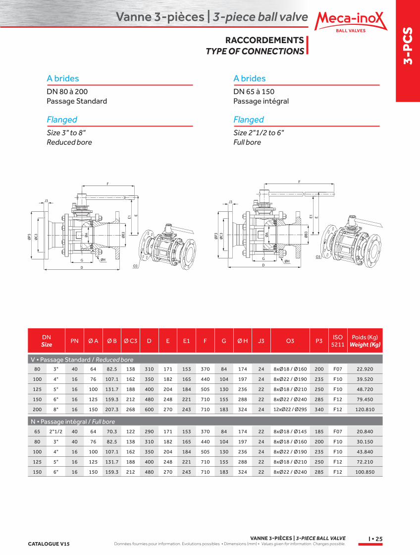
DNSize PN Ø A Ø B Ø C3 D E E1 F G Ø H J3 O3 P3
ISO5211
Poids (Kg)Weight (Kg)
V • Passage Standard / Reduced bore
N • Passage intégral / Full bore
80 3" 40 64 82.5 138 310 171 153 370 84 174 24 8xØ18 / Ø160 200 F07 22.920
100 4" 16 76 107.1 162 350 182 165 440 104 197 24 8xØ22 / Ø190 235 F10 39.520
125 5" 16 100 131.7 188 400 204 184 505 130 236 22 8xØ18 / Ø210 250 F10 48.720
150 6" 16 125 159.3 212 480 248 221 710 155 288 22 8xØ22 / Ø240 285 F12 79.450
200 8" 16 150 207.3 268 600 270 243 710 183 324 24 12xØ22 / Ø295 340 F12 120.810
65 2"1/2 40 64 70.3 122 290 171 153 370 84 174 22 8xØ18 / Ø145 185 F07 20.840
80 3" 40 76 82.5 138 310 182 165 440 104 197 24 8xØ18 / Ø160 200 F10 30.150
100 4" 16 100 107.1 162 350 204 184 505 130 236 24 8xØ22 / Ø190 235 F10 43.840
125 5" 16 125 131.7 188 400 248 221 710 155 288 22 8xØ18 / Ø210 250 F12 72.210
150 6" 16 150 159.3 212 480 270 243 710 183 324 22 8xØ22 / Ø240 285 F12 100.850
A bridesDN 80 à 200Passage Standard
FlangedSize 3" to 8"Reduced bore
A bridesDN 65 à 150Passage intégral
FlangedSize 2"1/2 to 6"Full bore
RACCORDEMENTSTYPE OF CONNECTIONS
Vanne 3-pièces | 3-piece ball valve
VANNE 3-PIÈCES | 3-PIECE BALL VALVEDonnées fournies pour information. Evolutions possibles • Dimensions (mm) • Values given for information. Changes possible. CATALOGUE V15
I • 26
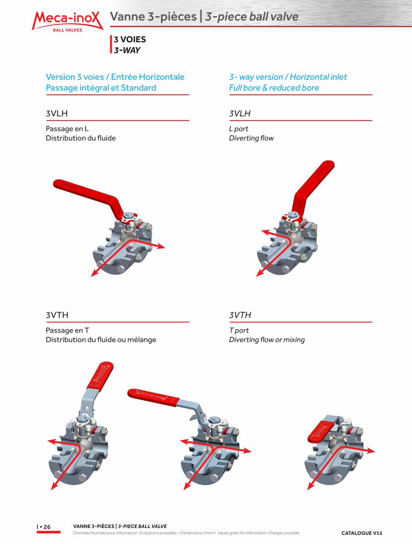
Version 3 voies / Entrée HorizontalePassage intégral et Standard
3- way version / Horizontal inletFull bore & reduced bore
3VLH
Passage en LDistribution du fluide
3VTH
Passage en TDistribution du fluide ou mélange
3VLH
L portDiverting flow
3VTH
T portDiverting flow or mixing
3 VOIES 3-WAY
Vanne 3-pièces | 3-piece ball valve
3-P
CS
CATALOGUE V15VANNE 3-PIÈCES | 3-PIECE BALL VALVE
Données fournies pour information. Evolutions possibles • Dimensions (mm) • Values given for information. Changes possible.I • 27
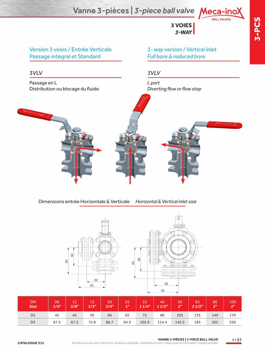
Version 3 voies / Entrée VerticalePassage intégral et Standard
3- way version / Vertical inletFull bore & reduced bore
3VLV
Passage en LDistribution ou blocage du fluide
3VLV
L portDiverting flow or flow stop
DNSize
081/4"
123/8"
151/2"
203/4"
251"
321 1/4"
401 1/2"
502"
652 1/2"
803"
1004"
D2 45 45 50 60 65 72 80 103 135 149 170
D3 67.3 67.3 72.8 86.7 94.3 102.9 114.4 142.5 183 202 220
Dimensions entrée Horizontale & Verticale Horizontal & Vertical inlet size
3 VOIES3-WAY
Vanne 3-pièces | 3-piece ball valve
VANNE 3-PIÈCES | 3-PIECE BALL VALVEDonnées fournies pour information. Evolutions possibles • Dimensions (mm) • Values given for information. Changes possible. CATALOGUE V15
I • 28
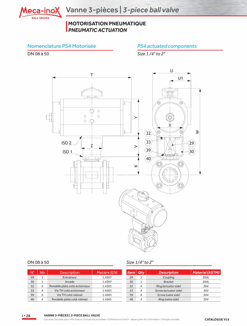
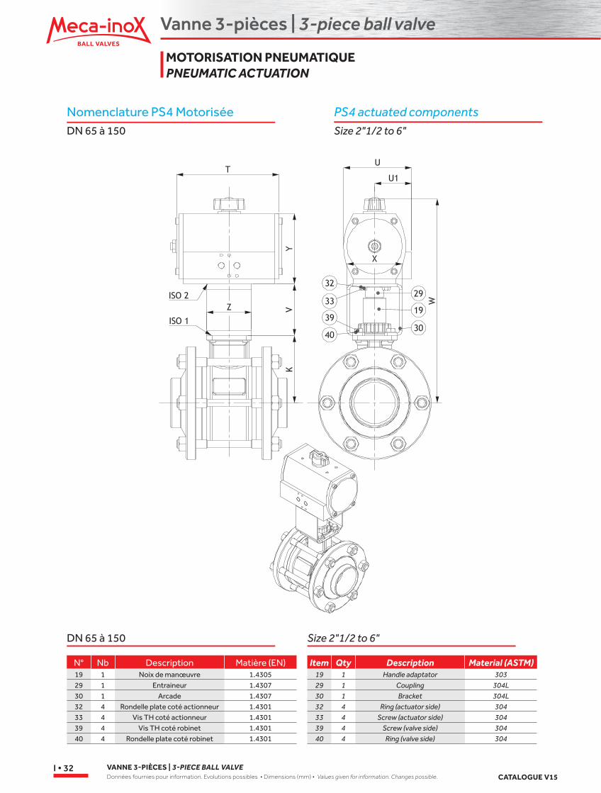
N° Nb Description Matière (EN)29 1 Entraineur 1.430730 1 Arcade 1.430732 4 Rondelle plate coté actionneur 1.430133 4 Vis TH coté actionneur 1.430139 4 Vis TH coté robinet 1.430140 4 Rondelle plate coté robinet 1.4301
Item Qty Description Material (ASTM)29 1 Coupling 304L30 1 Bracket 304L32 4 Ring (actuator side) 30433 4 Screw (actuator side) 30439 4 Screw (valve side) 30440 4 Ring (valve side) 304
PS4 actuated componentsSize 1 /4" to 2"
Nomenclature PS4 MotoriséeDN 08 à 50
DN 08 à 50 Size 1/4" to 2"
MOTORISATION PNEUMATIQUE PNEUMATIC ACTUATION
Vanne 3-pièces | 3-piece ball valve
3-P
CS
CATALOGUE V15VANNE 3-PIÈCES | 3-PIECE BALL VALVE
Données fournies pour information. Evolutions possibles • Dimensions (mm) • Values given for information. Changes possible.I • 29
PS4 actuatedSize 1 /4" to 2"
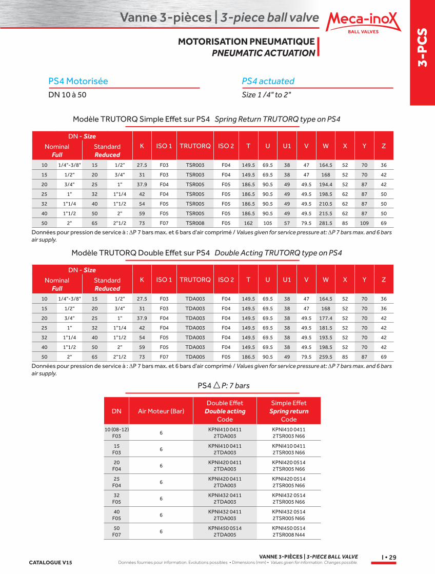
PS4 MotoriséeDN 10 à 50
Spring Return TRUTORQ type on PS4
Double Acting TRUTORQ type on PS4
P: 7 bars
Modèle TRUTORQ Simple Effet sur PS4
Modèle TRUTORQ Double Effet sur PS4
PS4
DN - SizeK ISO 1 TRUTORQ ISO 2 T U U1 V W X Y ZNominal
FullStandard Reduced
10 1/4"-3/8" 15 1/2" 27.5 F03 TSR003 F04 149.5 69.5 38 47 164.5 52 70 36
15 1/2" 20 3/4" 31 F03 TSR003 F04 149.5 69.5 38 47 168 52 70 42
20 3/4" 25 1" 37.9 F04 TSR005 F05 186.5 90.5 49 49.5 194.4 52 87 42
25 1" 32 1"1/4 42 F04 TSR005 F05 186.5 90.5 49 49.5 198.5 62 87 50
32 1"1/4 40 1"1/2 54 F05 TSR005 F05 186.5 90.5 49 49.5 210.5 62 87 50
40 1"1/2 50 2" 59 F05 TSR005 F05 186.5 90.5 49 49.5 215.5 62 87 50
50 2" 65 2"1/2 73 F07 TSR008 F05 162 105 57 79.5 281.5 85 109 69
Données pour pression de service à : ∆P 7 bars max. et 6 bars d'air comprimé / Values given for service pressure at: ∆P 7 bars max. and 6 bars air supply.
DN - SizeK ISO 1 TRUTORQ ISO 2 T U U1 V W X Y ZNominal
FullStandard Reduced
10 1/4"-3/8" 15 1/2" 27.5 F03 TDA003 F04 149.5 69.5 38 47 164.5 52 70 36
15 1/2" 20 3/4" 31 F03 TDA003 F04 149.5 69.5 38 47 168 52 70 36
20 3/4" 25 1" 37.9 F04 TDA003 F04 149.5 69.5 38 49.5 177.4 52 70 42
25 1" 32 1"1/4 42 F04 TDA003 F04 149.5 69.5 38 49.5 181.5 52 70 42
32 1"1/4 40 1"1/2 54 F05 TDA003 F04 149.5 69.5 38 49.5 193.5 52 70 42
40 1"1/2 50 2" 59 F05 TDA003 F04 149.5 69.5 38 49.5 198.5 52 70 42
50 2" 65 2"1/2 73 F07 TDA005 F05 186.5 90.5 49 79.5 259.5 85 87 69
Données pour pression de service à : ∆P 7 bars max. et 6 bars d'air comprimé / Values given for service pressure at: ∆P 7 bars max. and 6 bars air supply.
DN Air Moteur (Bar)Double Effet
Double acting Code
Simple Effet Spring return
Code10 (08-12)
F036
KPNI410 0411 2TDA003
KPNI410 0411 2TSR003 N66
15 F03
6KPNI410 0411
2TDA003KPNI410 0411 2TSR003 N66
20 F04
6KPNI420 0411
2TDA003KPNI420 0514 2TSR005 N66
25 F04
6KPNI420 0411
2TDA003KPNI420 0514 2TSR005 N66
32 F05
6KPNI432 0411
2TDA003KPNI432 0514 2TSR005 N66
40 F05
6KPNI432 0411
2TDA003KPNI432 0514 2TSR005 N66
50 F07
6KPNI450 0514
2TDA005KPNI450 0514 2TSR008 N44
MOTORISATION PNEUMATIQUE PNEUMATIC ACTUATION
Vanne 3-pièces | 3-piece ball valve
VANNE 3-PIÈCES | 3-PIECE BALL VALVEDonnées fournies pour information. Evolutions possibles • Dimensions (mm) • Values given for information. Changes possible. CATALOGUE V15
I • 30
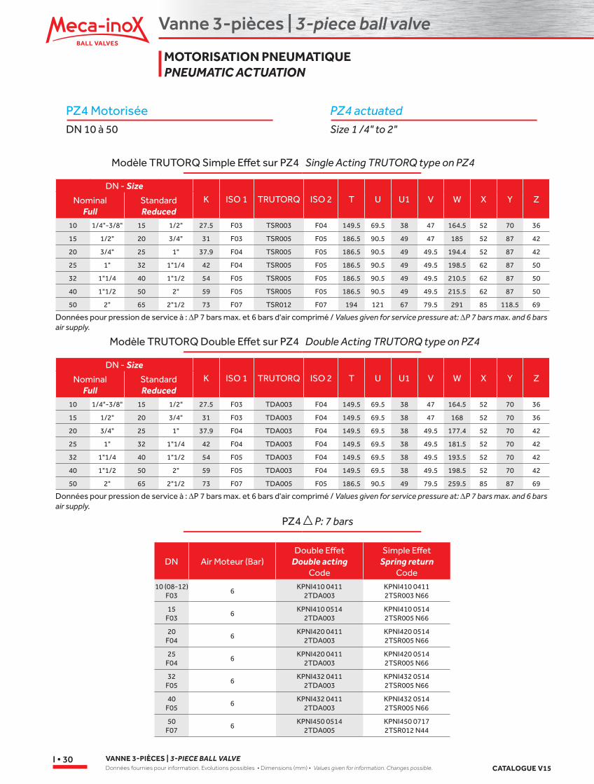
PZ4 actuatedSize 1 /4" to 2"
PZ4 MotoriséeDN 10 à 50
Single Acting TRUTORQ type on PZ4
Double Acting TRUTORQ type on PZ4
P: 7 bars
Modèle TRUTORQ Simple Effet sur PZ4
Modèle TRUTORQ Double Effet sur PZ4
PZ4
DN - SizeK ISO 1 TRUTORQ ISO 2 T U U1 V W X Y ZNominal
FullStandard Reduced
10 1/4"-3/8" 15 1/2" 27.5 F03 TSR003 F04 149.5 69.5 38 47 164.5 52 70 36
15 1/2" 20 3/4" 31 F03 TSR005 F05 186.5 90.5 49 47 185 52 87 42
20 3/4" 25 1" 37.9 F04 TSR005 F05 186.5 90.5 49 49.5 194.4 52 87 42
25 1" 32 1"1/4 42 F04 TSR005 F05 186.5 90.5 49 49.5 198.5 62 87 50
32 1"1/4 40 1"1/2 54 F05 TSR005 F05 186.5 90.5 49 49.5 210.5 62 87 50
40 1"1/2 50 2" 59 F05 TSR005 F05 186.5 90.5 49 49.5 215.5 62 87 50
50 2" 65 2"1/2 73 F07 TSR012 F07 194 121 67 79.5 291 85 118.5 69
Données pour pression de service à : ∆P 7 bars max. et 6 bars d'air comprimé / Values given for service pressure at: ∆P 7 bars max. and 6 bars air supply.
DN - SizeK ISO 1 TRUTORQ ISO 2 T U U1 V W X Y ZNominal
FullStandard Reduced
10 1/4"-3/8" 15 1/2" 27.5 F03 TDA003 F04 149.5 69.5 38 47 164.5 52 70 36
15 1/2" 20 3/4" 31 F03 TDA003 F04 149.5 69.5 38 47 168 52 70 36
20 3/4" 25 1" 37.9 F04 TDA003 F04 149.5 69.5 38 49.5 177.4 52 70 42
25 1" 32 1"1/4 42 F04 TDA003 F04 149.5 69.5 38 49.5 181.5 52 70 42
32 1"1/4 40 1"1/2 54 F05 TDA003 F04 149.5 69.5 38 49.5 193.5 52 70 42
40 1"1/2 50 2" 59 F05 TDA003 F04 149.5 69.5 38 49.5 198.5 52 70 42
50 2" 65 2"1/2 73 F07 TDA005 F05 186.5 90.5 49 79.5 259.5 85 87 69
Données pour pression de service à : ∆P 7 bars max. et 6 bars d'air comprimé / Values given for service pressure at: ∆P 7 bars max. and 6 bars air supply.
DN Air Moteur (Bar)Double Effet
Double acting Code
Simple Effet Spring return
Code10 (08-12)
F036
KPNI410 0411 2TDA003
KPNI410 0411 2TSR003 N66
15 F03
6KPNI410 0514
2TDA003KPNI410 0514 2TSR005 N66
20 F04
6KPNI420 0411
2TDA003KPNI420 0514 2TSR005 N66
25 F04
6KPNI420 0411
2TDA003KPNI420 0514 2TSR005 N66
32 F05
6KPNI432 0411
2TDA003KPNI432 0514 2TSR005 N66
40 F05
6KPNI432 0411
2TDA003KPNI432 0514 2TSR005 N66
50 F07
6KPNI450 0514
2TDA005KPNI450 0717 2TSR012 N44
MOTORISATION PNEUMATIQUE PNEUMATIC ACTUATION

Vanne 3-pièces | 3-piece ball valve
3-P
CS
CATALOGUE V15VANNE 3-PIÈCES | 3-PIECE BALL VALVE
Données fournies pour information. Evolutions possibles • Dimensions (mm) • Values given for information. Changes possible.I • 31
PY4 actuatedSize 1 /4" to 2"
PY4 MotoriséeDN 10 à 50
Spring Return TRUTORQ type on PY4
Double Acting TRUTORQ type on PY4
PY4 P : 40 bars (DN 10 - 32), 20 bars (DN 40- 50)
Modèle TRUTORQ Simple Effet sur PY4
Modèle TRUTORQ Double Effet sur PY4
DN - SizeK ISO 1 TRUTORQ ISO 2 T U U1 V W X Y ZNominal
FullStandard Reduced
10 1/4"-3/8" 15 1/2" 27.5 F03 2TSR003 F04 149.5 69.5 38 47 164.5 52 70 42
15 1/2" 20 3/4" 31 F03 2TSR005 F05 186.5 90.5 49 47 185 62 87 50
20 3/4" 25 1" 37.9 F04 2TSR005 F05 162 105 57 49.5 216.4 62 109 50
25 1" 32 1"1/4 42 F04 2TSR008 F07 194 121 67 49.5 230 82 118.5 69
32 1"1/4 40 1"1/2 54 F05 2TSR020 F07 218 136.5 72 49.5 264 82 140.5 69
40 1"1/2 50 2" 59 F05 2TSR020 F10 218 136.5 72 49.5 269 82 140.5 69
50 2" 65 2"1/2 73 F07 2TSR035 F10 266 156 78 79.5 339 120 166.5 105
Données pour température de service cryogénique (-196 °C) et 6 bars d'air comprimé à : ∆P 40 bars Max (DN 10 à 32), ∆P 20 bars Max (DN40 à 50)Values given for cryogenics service (- l 96°C) and 6 bars air supply pressure at: ∆P 40 bars Max (DN 10 to 32), ∆P 20 bars Max (DN40 to 50)
DN - SizeK ISO 1 TRUTORQ ISO 2 T U U1 V W X Y ZNominal
FullStandard Reduced
10 1/4"-3/8" 15 1/2" 27.5 F03 2TDA003 F04 14.95 69.5 38 47 164.5 52 70 42
15 1/2" 20 3/4" 31 F03 2TDA003 F04 149.5 69.5 38 47 168 52 70 42
20 3/4" 25 1" 37.9 F04 2TDA003 F04 149.5 69.5 38 49.5 177.4 62 70 50
25 1" 32 1"1/4 42 F04 2TDA005 F05 186.5 90.5 49 49.5 198.5 62 87 50
32 1"1/4 40 1"1/2 54 F05 2TDA005 F05 186.5 90.5 49 49.5 210.5 62 87 50
40 1"1/2 50 2" 59 F05 2TDA008 F05 162 105 57 49.5 237.5 62 109 50
50 2" 65 2"1/2 73 F07 2TDA012 F07 194 121 67 79.5 291 85 118.5 69
Données pour température de service cryogénique (-196 °C) et 6 bars d'air comprimé à : ∆P 40 bars Max (DN 10 à 32), ∆P 20 bars Max (DN40 à 50)Values given for cryogenics service (- l 96°C) and 6 bars air supply pressure at: ∆P 40 bars Max (DN 10 to 32), ∆P 20 bars Max (DN40 to 50)
DN Air Moteur (Bar)Double Effet
Double acting Code
Simple Effet Spring return
Code10
F036
KPNI410 0411 2TDA003
KPNI410 0411 2TSR003 N66
15 F03
6KPNI410 0411
2TDA003KPNI410 0514 2TSR005 N66
20 F04
6KPNI420 0411
2TDA003KPNI420 0514 2TSR005 N66
25 F04
6KPNI420 0514
2TDA005KPNI420 0514 2TSR008 N44
32 F05
6KPNI432 0514
2TDA005KPNI432 0717 2TSR020 N44
40 F05
6KPNI432 0514
2TDA008KPNI432 0717 2TSR020 N44
50 F07
6KPNI450 0717
2TDA012KPNI450 1022 2TSR035 N44
MOTORISATION PNEUMATIQUE PNEUMATIC ACTUATION
Vanne 3-pièces | 3-piece ball valve
VANNE 3-PIÈCES | 3-PIECE BALL VALVEDonnées fournies pour information. Evolutions possibles • Dimensions (mm) • Values given for information. Changes possible. CATALOGUE V15
I • 32
N° Nb Description Matière (EN)19 1 Noix de manœuvre 1.430529 1 Entraineur 1.430730 1 Arcade 1.430732 4 Rondelle plate coté actionneur 1.430133 4 Vis TH coté actionneur 1.430139 4 Vis TH coté robinet 1.430140 4 Rondelle plate coté robinet 1.4301
Item Qty Description Material (ASTM)19 1 Handle adaptator 30329 1 Coupling 304L30 1 Bracket 304L32 4 Ring (actuator side) 30433 4 Screw (actuator side) 30439 4 Screw (valve side) 30440 4 Ring (valve side) 304
PS4 actuated componentsSize 2"1/2 to 6"
Nomenclature PS4 MotoriséeDN 65 à 150
DN 65 à 150 Size 2"1/2 to 6"
MOTORISATION PNEUMATIQUE PNEUMATIC ACTUATION
Vanne 3-pièces | 3-piece ball valve
3-P
CS
CATALOGUE V15VANNE 3-PIÈCES | 3-PIECE BALL VALVE
Données fournies pour information. Evolutions possibles • Dimensions (mm) • Values given for information. Changes possible.I • 33
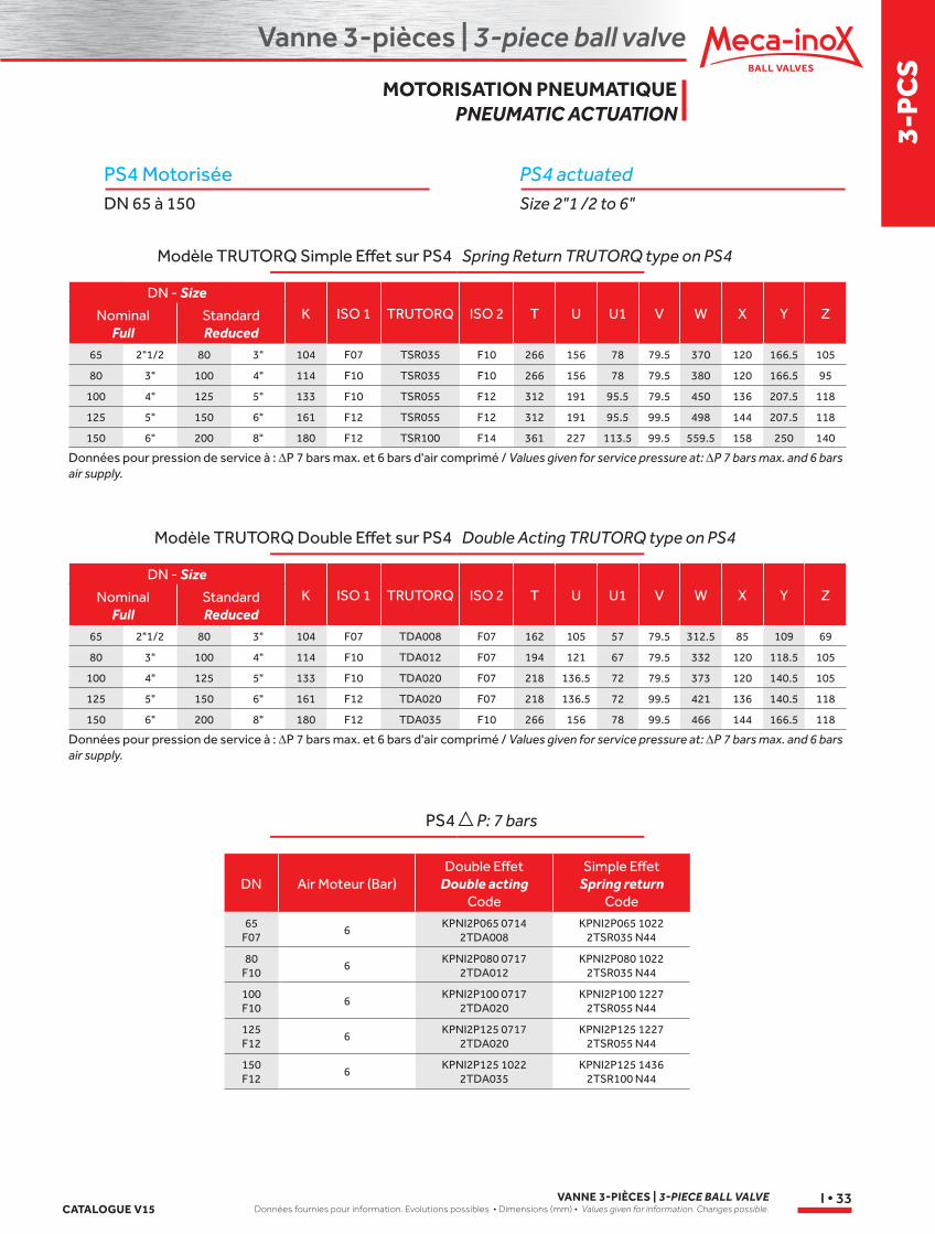
PS4 actuatedSize 2"1 /2 to 6"
PS4 MotoriséeDN 65 à 150
Spring Return TRUTORQ type on PS4
Double Acting TRUTORQ type on PS4
P: 7 bars
Modèle TRUTORQ Simple Effet sur PS4
Modèle TRUTORQ Double Effet sur PS4
PS4
DN - SizeK ISO 1 TRUTORQ ISO 2 T U U1 V W X Y ZNominal
FullStandard Reduced
65 2"1/2 80 3" 104 F07 TSR035 F10 266 156 78 79.5 370 120 166.5 105
80 3" 100 4" 114 F10 TSR035 F10 266 156 78 79.5 380 120 166.5 95
100 4" 125 5" 133 F10 TSR055 F12 312 191 95.5 79.5 450 136 207.5 118
125 5" 150 6" 161 F12 TSR055 F12 312 191 95.5 99.5 498 144 207.5 118
150 6" 200 8" 180 F12 TSR100 F14 361 227 113.5 99.5 559.5 158 250 140
Données pour pression de service à : ∆P 7 bars max. et 6 bars d'air comprimé / Values given for service pressure at: ∆P 7 bars max. and 6 bars air supply.
DN - SizeK ISO 1 TRUTORQ ISO 2 T U U1 V W X Y ZNominal
FullStandard Reduced
65 2"1/2 80 3" 104 F07 TDA008 F07 162 105 57 79.5 312.5 85 109 69
80 3" 100 4" 114 F10 TDA012 F07 194 121 67 79.5 332 120 118.5 105
100 4" 125 5" 133 F10 TDA020 F07 218 136.5 72 79.5 373 120 140.5 105
125 5" 150 6" 161 F12 TDA020 F07 218 136.5 72 99.5 421 136 140.5 118
150 6" 200 8" 180 F12 TDA035 F10 266 156 78 99.5 466 144 166.5 118
Données pour pression de service à : ∆P 7 bars max. et 6 bars d'air comprimé / Values given for service pressure at: ∆P 7 bars max. and 6 bars air supply.
DN Air Moteur (Bar)Double Effet
Double acting Code
Simple Effet Spring return
Code65
F076
KPNI2P065 0714 2TDA008
KPNI2P065 1022 2TSR035 N44
80 F10
6KPNI2P080 0717
2TDA012KPNI2P080 1022
2TSR035 N44
100 F10
6KPNI2P100 0717
2TDA020KPNI2P100 1227
2TSR055 N44
125 F12
6KPNI2P125 0717
2TDA020KPNI2P125 1227
2TSR055 N44
150 F12
6KPNI2P125 1022
2TDA035KPNI2P125 1436
2TSR100 N44
MOTORISATION PNEUMATIQUE PNEUMATIC ACTUATION
Vanne 3-pièces | 3-piece ball valve
VANNE 3-PIÈCES | 3-PIECE BALL VALVEDonnées fournies pour information. Evolutions possibles • Dimensions (mm) • Values given for information. Changes possible. CATALOGUE V15
I • 34
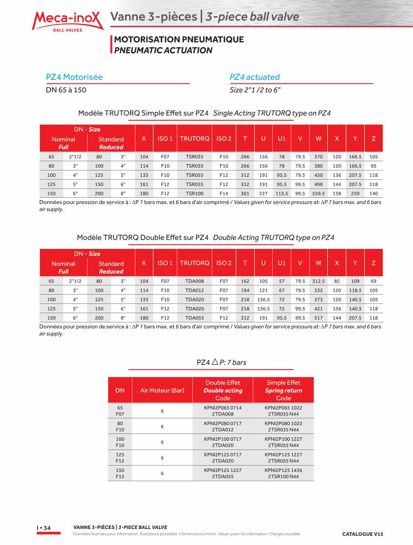
PZ4 actuatedSize 2"1 /2 to 6"
PZ4 MotoriséeDN 65 à 150
Single Acting TRUTORQ type on PZ4
Double Acting TRUTORQ type on PZ4
P: 7 bars
Modèle TRUTORQ Simple Effet sur PZ4
Modèle TRUTORQ Double Effet sur PZ4
PZ4
DN - SizeK ISO 1 TRUTORQ ISO 2 T U U1 V W X Y ZNominal
FullStandard Reduced
65 2"1/2 80 3" 104 F07 TSR035 F10 266 156 78 79.5 370 120 166.5 105
80 3" 100 4" 114 F10 TSR035 F10 266 156 78 79.5 380 120 166.5 95
100 4" 125 5" 133 F10 TSR055 F12 312 191 95.5 79.5 450 136 207.5 118
125 5" 150 6" 161 F12 TSR055 F12 312 191 95.5 99.5 498 144 207.5 118
150 6" 200 8" 180 F12 TSR100 F14 361 227 113.5 99.5 559.5 158 250 140
Données pour pression de service à : ∆P 7 bars max. et 6 bars d'air comprimé / Values given for service pressure at: ∆P 7 bars max. and 6 bars air supply.
DN - SizeK ISO 1 TRUTORQ ISO 2 T U U1 V W X Y ZNominal
FullStandard Reduced
65 2"1/2 80 3" 104 F07 TDA008 F07 162 105 57 79.5 312.5 85 109 69
80 3" 100 4" 114 F10 TDA012 F07 194 121 67 79.5 332 120 118.5 105
100 4" 125 5" 133 F10 TDA020 F07 218 136.5 72 79.5 373 120 140.5 105
125 5" 150 6" 161 F12 TDA020 F07 218 136.5 72 99.5 421 136 140.5 118
150 6" 200 8" 180 F12 TDA055 F12 312 191 95.5 99.5 517 144 207.5 118
Données pour pression de service à : ∆P 7 bars max. et 6 bars d'air comprimé / Values given for service pressure at: ∆P 7 bars max. and 6 bars air supply.
DN Air Moteur (Bar)Double Effet
Double acting Code
Simple Effet Spring return
Code65
F076
KPNI2P065 0714 2TDA008
KPNI2P065 1022 2TSR035 N44
80 F10
6KPNI2P080 0717
2TDA012KPNI2P080 1022
2TSR035 N44
100 F10
6KPNI2P100 0717
2TDA020KPNI2P100 1227
2TSR055 N44
125 F12
6KPNI2P125 0717
2TDA020KPNI2P125 1227
2TSR055 N44
150 F12
6KPNI2P125 1227
2TDA055KPNI2P125 1436
2TSR100 N44
MOTORISATION PNEUMATIQUE PNEUMATIC ACTUATION
Vanne 3-pièces | 3-piece ball valve
3-P
CS
CATALOGUE V15VANNE 3-PIÈCES | 3-PIECE BALL VALVE
Données fournies pour information. Evolutions possibles • Dimensions (mm) • Values given for information. Changes possible.I • 35
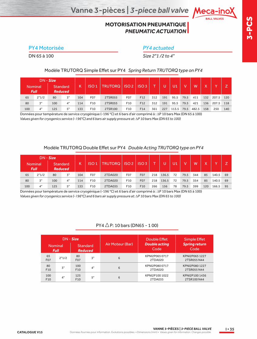
PY4 actuatedSize 2"1 /2 to 4"
PY4 MotoriséeDN 65 à 100
Spring Return TRUTORQ type on PY4
Double Acting TRUTORQ type on PY4
PY4 P: 10 bars (DN65 - 1 00)
Modèle TRUTORQ Simple Effet sur PY4
Modèle TRUTORQ Double Effet sur PY4
DN - SizeK ISO 1 TRUTORQ ISO 2 ISO 3 T U U1 V W X Y ZNominal
FullStandard Reduced
65 2"1/2 80 3" 104 F07 2TSR055 F07 F12 312 191 95.5 79.5 411 132 207.5 120
80 3" 100 4" 114 F10 2TSR055 F10 F12 312 191 95.5 79.5 421 136 207.5 118
100 4" 125 5" 133 F10 2TSR100 F10 F14 361 227 113.5 79.5 482.5 158 250 140
Données pour température de service cryogénique (-196 °C) et 6 bars d'air comprimé à : ∆P 10 bars Max (DN 65 à 100)Values given for cryogenics service (- l 96°C) and 6 bars air supply pressure at: ∆P 10 bars Max (DN 65 to 100)
DN - SizeK ISO 1 TRUTORQ ISO 2 ISO 3 T U U1 V W X Y ZNominal
FullStandard Reduced
65 2"1/2 80 3" 104 F07 2TDA020 F07 F07 218 136.5 72 79.5 344 85 140.5 69
80 3" 100 4" 114 F10 2TDA020 F10 F07 218 136.5 72 79.5 354 85 140.5 69
100 4" 125 5" 133 F10 2TDA035 F10 F10 266 156 78 79.5 399 120 166.5 95
Données pour température de service cryogénique (-196 °C) et 6 bars d'air comprimé à : ∆P 10 bars Max (DN 65 à 100)Values given for cryogenics service (- l 96°C) and 6 bars air supply pressure at: ∆P 10 bars Max (DN 65 to 100)
DN - SizeAir Moteur (Bar)
Double Effet Double acting
Code
Simple Effet Spring return
CodeNominal
FullStandard Reduced
65 F07
2"1/280
F073" 6
KPNI2P065 0717 2TDA020
KPNI2P065 1227 2TSR055 N44
80 F10
3"100 F10
4" 6KPNI2P080 0717
2TDA020KPNI2P080 1227
2TSR055 N44
100 F10
4"125 F10
5" 6KPNI2P100 1022
2TDA035KPNI2P100 1436
2TSR100 N44
MOTORISATION PNEUMATIQUE PNEUMATIC ACTUATION