Embed Size (px)
Citation preview

Variable Frequency 101
Joe Evans, Ph.D
[email protected] http://www.pumped101.com
The rotational speed of an AC induction motor depends upon two components - - the number
of poles (windings) in its stator and the frequency of the AC power source. Increase the
number of poles and the rotational speed decreases. The opposite occurs with a change in
frequency. Increase the frequency and rotational speed increases - - decrease frequency and
rotational speed decreases. The nice thing about frequency is that it can be easily changed.
This is not the case for the number of motor poles because, once a motor is built it stays that
way for life. Variable Frequency Drives (VFD’s) take advantage of both when controlling
motor speed. If you gain an understanding of frequency and how a motor is wound you will
find that understanding the VFD will be quite straight forward. Lets start our discussion by
taking a look at the component known as frequency or cycles per second .
Frequency (The AC Wave Form)
Exactly what do we mean when we refer to the frequency of AC power? Well, we probably
all know that AC stands for “alternating current”. Unlike direct current (DC), where voltage
remains the same with respect to time, alternating current moves back and forth (or up and
down) from some positive voltage or current to some negative voltage or current. Because of
these oscillations, AC is more complex and, it is for this reason that DC almost became the
standard in the US. Fortunately Mr. Edison lost this battle because, even though it is more
complex, AC is the better solution to our general electrical needs.
The illustration below compares a DC “wave”, produced by a battery or generator, with that
of a single phase AC sine wave produced by a power utility. The DC “wave” remains flat (or
at the same voltage) from beginning to end. If it were generated at 12V it will remain at 12V
as long the power is on. Not true for AC - - notice that it begins at zero volts and rises to some
maximum positive voltage and then falls again to zero volts. It continues falling to some
maximum negative voltage and then begins rising to zero volts. This progression is known as
one AC cycle. In the US one complete AC cycle occurs 60 times each second and its frequency
is referred to as 60 cycles per second or 60 Hz (Hertz).
Vo
ltag
e
Time
12V DC 60 HZ AC
Pump ED 101

Now, don’t get confused when I tend to alternate (pun intended) the usage of current and
voltage when referring to AC. Both are components of AC power and produce similar curves.
For a detailed look at voltage and current or, for that matter, all of the components of AC
download my AC Power tutorial.
Why 60 Hz - - why not 30 Hz ? Well, it really doesn’t matter all that much if the power is
being used by a resistive circuit (incandescent lights, heaters, etc). As long as its 30 Hz and
above, incandescent lights will not flicker and power, in watts, is still volts times amps
regardless of the frequency. There are several reasons why higher frequencies are better
suited for inductive devices (motors and transformers) but we will not address them here.
Tesla, the inventor of the AC induction motor and generator, decided upon 60 Hz but it was
some years later that his became the standard in the US. Early on, generators with outputs as
low as 25 Hz were common. For some reason, (one which I have yet to find the answer)
Europe standardized on 50 Hz. I suspect that it had something to do with the French or
possibly the Germans but, I digress as this is purely a political hypothesis. The figures below
compare the AC wave form seen in the previous illustration to those generated at a lower and
higher frequency.
As you can see, the amplitudes are the same. Only the number of up and down motions per
unit time differ. During the same period of time, the 30 Hz wave completes just half a cycle
compared to a full cycle for the 60 Hz wave while the 120 Hz wave completes two. In the
examples above, frequency is dependent upon the rotational speed of the generator. Increase
generator speed and frequency increases, lower its speed and frequency decreases. It is as
simple as that! And, the frequency of the AC wave has a direct relationship with the
rotational speed of the electric motor it powers.
Motor Windings (Poles or Pole Pairs)
Hopefully the previous section has given you a basic understanding of the definition of
frequency as it applies to alternating current and the wave form a generator produces. Lets
take this information and apply it to the AC induction motor and the rotational speed it can
attain based upon the frequency of the power applied and the manner in which it is wound.
60 Hz 30 Hz 120 Hz

The illustration to the right is that of a two pole, single phase motor
stator. It contains two windings (poles), wired in series, and
separated by 180 degrees. As the AC wave form rises from zero to
its maximum positive voltage, the upper pole has a north (N)
polarity while the lower pole has a south (S) polarity. When the
wave form changes direction and begins to fall, the poles change
polarity and then change yet again when the wave begins another
upward rise. These polarity changes in the stator poles induce
magnetic fields in the motor rotor which oppose those in the poles.
And, it is this opposition to one another that causes the rotor to
rotate. One complete AC wave cycle (regardless of its frequency)
will cause the rotor of the two pole motor to complete a single rotation. If the AC frequency is
60 Hz the motor will rotate at 3600 RPM (60 rotations per second times 60 seconds). At 50 Hz
the rotational speed will be 3000 RPM and at 30 Hz it will rotate at 1800 RPM.
If we were to increase the number of poles in the stator to four, the rotational speed would be
halved. Why? Because the poles are, once again, wired in series and it takes two AC cycles to
circumnavigate the stator. Therefore it takes twice as long to produce a single rotation of the
rotor. In the case of the four pole motor, two complete AC wave cycles will cause the rotor to
complete a single rotation and do so regardless of the frequency. At 60 Hz the rotational
speed will be 1800 RPM. At 50 Hz it will rotate at 1500 RPM and at 30 Hz its rotational speed
will be 900 RPM. A six pole motor operated at 60 Hz will rotate at 1200 RPM while an eight
pole unit will at the same frequency will do 900 RPM. The following equation will allow you
to compute rotational speed of any motor if you know the frequency and the number of motor
poles. RPM = (frequency X 120) / # poles
For a more detailed discussion of AC motor components and rotational fields, download
The Single Phase Induction Motor and The AC Induction Motor tutorials at Pump Ed 101.
By now you should have a pretty good understanding of the relationship between AC
frequency and the number of motor poles as they pertain to the rotational speed of an electric
motor. Lets move on to the VFD and how it controls motor speed.
Variable Speed Operation
Variable frequency operation has been around, in the form of the AC generator, since the
advent of the induction motor. Change the rotational speed of a generator and you change its
output frequency. Before the advent of high speed transistors, this was one of the few options
available to vary motor speed, however, frequency changes were limited because generator
speed reduction lowered the output frequency but not the voltage. We will see why this is
important a little later. In our industry, variable speed pumping applications were far more
complex in the past than they are today. One of the simpler methods was to employ a multi
pole motor that was wound in such a way that allowed a switch (or switches) to vary the
number of stator poles that were active at any given time. Rotational speed could be changed
manually or by a sensor connected to the switches. Many variable flow pumping applications
still employ this method. Examples include hot & chilled water circulators, pool pumps, and
cooling tower fans & pumps. Some domestic booster pumps used fluid drive or variable belt
drive systems (an automatic transmission of sorts) to vary pump speed based on feedback
from a pressure diaphragm valve. And, several others were even more complex.
Based upon the hoops we had to jump through in the past, it becomes pretty apparent why
the advent of the modern AC Variable Frequency Drive revolutionized (yet another pun) the
variable speed pumping environment. All you have to do today is install a relatively simple
electronic box (that often replaces more complex starting equipment) at the application site
and, suddenly you can, either manually or automatically, change pump speed to your heart’s
desire.
So, lets take a look at the components of an AC Drive and see how they actually function
together to vary frequency and thus motor speed. I think you will be amazed at the simplicity
of the process. All it took was the maturing of the solid state device we know as the transistor.
VFD Components
The Rectifier
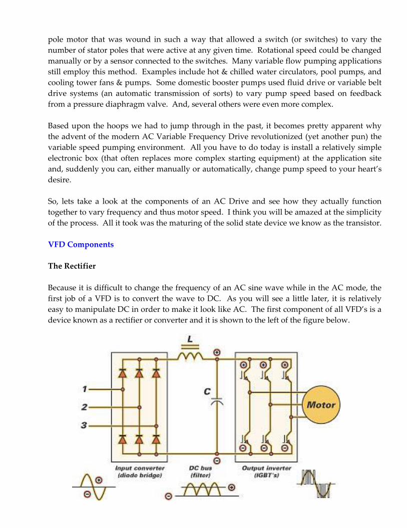
Because it is difficult to change the frequency of an AC sine wave while in the AC mode, the
first job of a VFD is to convert the wave to DC. As you will see a little later, it is relatively
easy to manipulate DC in order to make it look like AC. The first component of all VFD’s is a
device known as a rectifier or converter and it is shown to the left of the figure below.

The rectifier circuit converts AC to DC and does so in much the same manner as those of a
battery charger or arc welder. It uses a diode bridge to limit the travel of the AC sine wave to
one direction only. The result is a fully rectified AC wave form that is interpreted by a DC
circuit as a native DC wave form. Three phase drives accept three separate AC input phases
and convert them to a single DC output. Most three phase drives can also accept single phase
(230V or 460V) power but, since there are only two incoming legs, the drive’s output (HP)
must be derated because the DC current produced is reduced proportionally. On the other
hand, true single phase VFD’s (those that control single phase motors) utilize a single phase
input and produce a DC output that is proportional to the input.
There are two reasons why three phase motors are more popular than their single phase
counter parts when it comes to variable speed operation. First they offer a much wider power
range. But, equally as important is their ability to begin rotation on their own. A single phase
motor, on the other hand, often requires some outside intervention to begin rotation. In this
case, we will limit our discussion to three phase motors used on three phase drives.
The DC Bus
The second component, known as the DC Bus (shown in the center of the illustration) is not
seen and in all VFD’s because it does not contribute directly to variable frequency operation.
But, it will always be there in high quality, general purpose drives (those manufactured by
dedicated drive manufacturers). Without getting into a lot of detail, the DC Bus uses
capacitors and an inductor to filter the AC “ripple” voltage from the converted DC before it
enters the inverter section. It can also include filters which impede harmonic distortion that
can feed back into the power source supplying the VFD. Older VFD’s and some pump specific
drives require separate line filters to accomplish this task. (See the “Distorted Wave Puzzler”
for more information on this subject)
The Inverter
To the right of the illustration is the “guts” of the VFD. The inverter uses three sets of high
speed switching transistors to create DC “pulses” that emulate all three phases of the AC sine
wave. These pulses not only dictate the voltage of the wave but also its frequency. The term
inverter or inversion means “reversal” and simply refers to the up and down motion of the
generated wave form. The modern VFD inverter uses a technique known as “Pulse Width
Modulation” (PWM) to regulate voltage and frequency. We will cover this in more detail
when we look at the output of the inverter.
Another term you have probably run across when reading VFD literature or advertisements is
“IGBT”. IGBT refers to the “Insulated Gate, Bipolar Transistor” which is the switching (or
pulsing) component of the inverter. The transistor (which replaced the vacuum tube) serves
two functions in our electronic world. It can act as an amplifier and increase a signal as it does
in a radio or stereo or, it can act as a switch and simply turn a signal on and off. The IGBT is
simply a modern version that provides higher switching speeds (3000 – 16000 Hz) and
reduced heat generation. The higher switching speed results in increased accuracy of AC
wave emulation and reduced audible motor noise. A reduction in generated heat means
smaller heat sinks and thus a smaller drive footprint.
Inverter Output
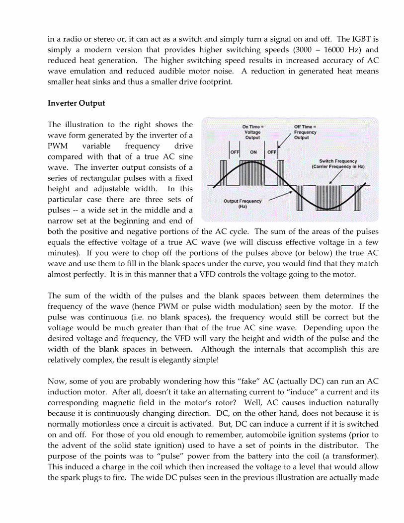
The illustration to the right shows the
wave form generated by the inverter of a
PWM variable frequency drive
compared with that of a true AC sine
wave. The inverter output consists of a
series of rectangular pulses with a fixed
height and adjustable width. In this
particular case there are three sets of
pulses -- a wide set in the middle and a
narrow set at the beginning and end of
both the positive and negative portions of the AC cycle. The sum of the areas of the pulses
equals the effective voltage of a true AC wave (we will discuss effective voltage in a few
minutes). If you were to chop off the portions of the pulses above (or below) the true AC
wave and use them to fill in the blank spaces under the curve, you would find that they match
almost perfectly. It is in this manner that a VFD controls the voltage going to the motor.
The sum of the width of the pulses and the blank spaces between them determines the
frequency of the wave (hence PWM or pulse width modulation) seen by the motor. If the
pulse was continuous (i.e. no blank spaces), the frequency would still be correct but the
voltage would be much greater than that of the true AC sine wave. Depending upon the
desired voltage and frequency, the VFD will vary the height and width of the pulse and the
width of the blank spaces in between. Although the internals that accomplish this are
relatively complex, the result is elegantly simple!
Now, some of you are probably wondering how this “fake” AC (actually DC) can run an AC
induction motor. After all, doesn’t it take an alternating current to “induce” a current and its
corresponding magnetic field in the motor’s rotor? Well, AC causes induction naturally
because it is continuously changing direction. DC, on the other hand, does not because it is
normally motionless once a circuit is activated. But, DC can induce a current if it is switched
on and off. For those of you old enough to remember, automobile ignition systems (prior to
the advent of the solid state ignition) used to have a set of points in the distributor. The
purpose of the points was to “pulse” power from the battery into the coil (a transformer).
This induced a charge in the coil which then increased the voltage to a level that would allow
the spark plugs to fire. The wide DC pulses seen in the previous illustration are actually made
up of hundreds of individual pulses and, it is this on and off motion of the inverter output
that allows induction via DC to occur.
Effective Voltage
AC power is a rather complex quantity and it is no wonder that Edison almost won the battle
to make DC the standard in the US. Fortunately, for us, all of its complexities have been
explained and all we have to do is follow the rules those before us have laid out.
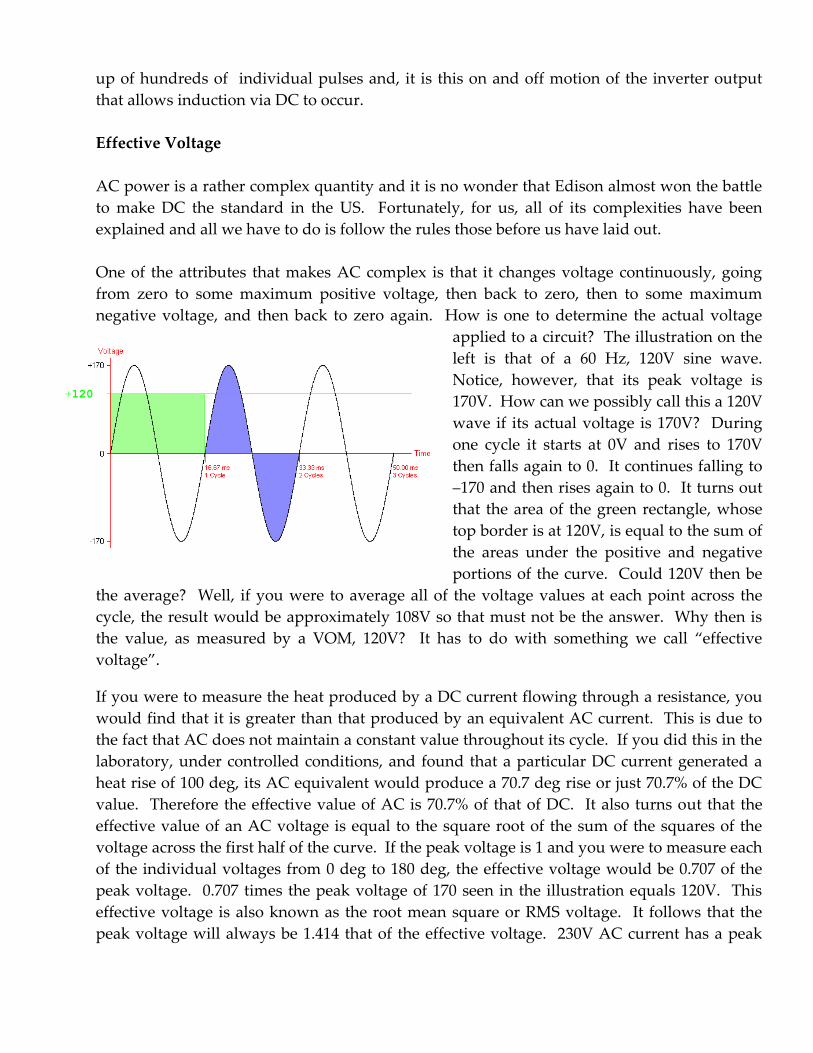
One of the attributes that makes AC complex is that it changes voltage continuously, going
from zero to some maximum positive voltage, then back to zero, then to some maximum
negative voltage, and then back to zero again. How is one to determine the actual voltage
applied to a circuit? The illustration on the
left is that of a 60 Hz, 120V sine wave.
Notice, however, that its peak voltage is
170V. How can we possibly call this a 120V
wave if its actual voltage is 170V? During
one cycle it starts at 0V and rises to 170V
then falls again to 0. It continues falling to
–170 and then rises again to 0. It turns out
that the area of the green rectangle, whose
top border is at 120V, is equal to the sum of
the areas under the positive and negative
portions of the curve. Could 120V then be
the average? Well, if you were to average all of the voltage values at each point across the
cycle, the result would be approximately 108V so that must not be the answer. Why then is
the value, as measured by a VOM, 120V? It has to do with something we call “effective
voltage”.
If you were to measure the heat produced by a DC current flowing through a resistance, you
would find that it is greater than that produced by an equivalent AC current. This is due to
the fact that AC does not maintain a constant value throughout its cycle. If you did this in the
laboratory, under controlled conditions, and found that a particular DC current generated a
heat rise of 100 deg, its AC equivalent would produce a 70.7 deg rise or just 70.7% of the DC
value. Therefore the effective value of AC is 70.7% of that of DC. It also turns out that the
effective value of an AC voltage is equal to the square root of the sum of the squares of the
voltage across the first half of the curve. If the peak voltage is 1 and you were to measure each
of the individual voltages from 0 deg to 180 deg, the effective voltage would be 0.707 of the
peak voltage. 0.707 times the peak voltage of 170 seen in the illustration equals 120V. This
effective voltage is also known as the root mean square or RMS voltage. It follows that the
peak voltage will always be 1.414 that of the effective voltage. 230V AC current has a peak
+120
voltage of 325V while 460 has a peak voltage of 650V. We will see the effects of peak voltage a
little later.
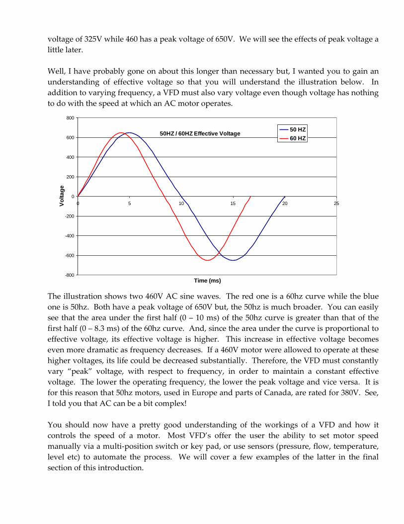
Well, I have probably gone on about this longer than necessary but, I wanted you to gain an
understanding of effective voltage so that you will understand the illustration below. In
addition to varying frequency, a VFD must also vary voltage even though voltage has nothing
to do with the speed at which an AC motor operates.
The illustration shows two 460V AC sine waves. The red one is a 60hz curve while the blue
one is 50hz. Both have a peak voltage of 650V but, the 50hz is much broader. You can easily
see that the area under the first half (0 – 10 ms) of the 50hz curve is greater than that of the
first half (0 – 8.3 ms) of the 60hz curve. And, since the area under the curve is proportional to
effective voltage, its effective voltage is higher. This increase in effective voltage becomes
even more dramatic as frequency decreases. If a 460V motor were allowed to operate at these
higher voltages, its life could be decreased substantially. Therefore, the VFD must constantly
vary “peak” voltage, with respect to frequency, in order to maintain a constant effective
voltage. The lower the operating frequency, the lower the peak voltage and vice versa. It is
for this reason that 50hz motors, used in Europe and parts of Canada, are rated for 380V. See,
I told you that AC can be a bit complex!
You should now have a pretty good understanding of the workings of a VFD and how it
controls the speed of a motor. Most VFD’s offer the user the ability to set motor speed
manually via a multi-position switch or key pad, or use sensors (pressure, flow, temperature,
level etc) to automate the process. We will cover a few examples of the latter in the final
section of this introduction.
50HZ / 60HZ Effective Voltage
-800
-600
-400
-200
0
200
400
600
800
0 5 10 15 20 25
Time (ms)
Vo
lta
ge
50 HZ
60 HZ
Potential Problems
Someone once said that “there is no such thing as a free lunch” and, this is certainly the case
with the VFD. Problems can and often will arise. They are not yet fool proof (I like to use the
term “fool resistant” because nothing can be truly “fool proof”) so caution is advised when
applying a VFD to a pumping application. There are four major categories of problems that
can occur in a VFD installation -- motor bearing damage, the production of harmonics,
motor insulation damage, and resonant frequency. I will mention the first two briefly and go
into detail on the last two.
Motor Bearing Damage
Bearing currents have been around since the advent of the electric motor but the
incidence of damage they cause has increased with the growth of VFD usage.
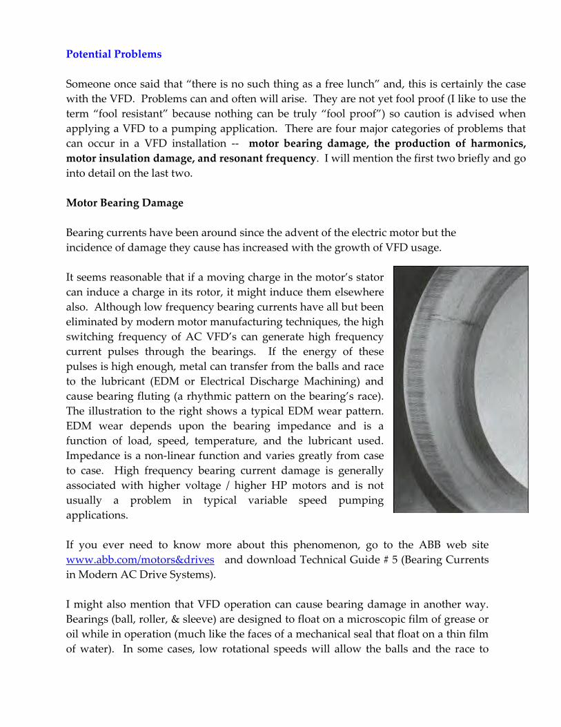
It seems reasonable that if a moving charge in the motor’s stator
can induce a charge in its rotor, it might induce them elsewhere
also. Although low frequency bearing currents have all but been
eliminated by modern motor manufacturing techniques, the high
switching frequency of AC VFD’s can generate high frequency
current pulses through the bearings. If the energy of these
pulses is high enough, metal can transfer from the balls and race
to the lubricant (EDM or Electrical Discharge Machining) and
cause bearing fluting (a rhythmic pattern on the bearing’s race).
The illustration to the right shows a typical EDM wear pattern.
EDM wear depends upon the bearing impedance and is a
function of load, speed, temperature, and the lubricant used.
Impedance is a non-linear function and varies greatly from case
to case. High frequency bearing current damage is generally
associated with higher voltage / higher HP motors and is not
usually a problem in typical variable speed pumping
applications.
If you ever need to know more about this phenomenon, go to the ABB web site
www.abb.com/motors&drives and download Technical Guide # 5 (Bearing Currents
in Modern AC Drive Systems).
I might also mention that VFD operation can cause bearing damage in another way.
Bearings (ball, roller, & sleeve) are designed to float on a microscopic film of grease or
oil while in operation (much like the faces of a mechanical seal that float on a thin film
of water). In some cases, low rotational speeds will allow the balls and the race to
come into contact during operation and accelerate bearing wear. This is even more of
a problem when the motor has a high radial load (belt drive etc).
Harmonics
Harmonics (noise caused by the high switching frequency of a VFD) affect the power
supply side of the drive and all circuits connected to that supply. Its effect can range
from annoying hums and flickering lights (& computer displays) to more serious
problems such as the overheating of wiring and its connected devices to tripped
circuit breakers. Usually a single PWM drive, that incorporates a DC Bus section, is a
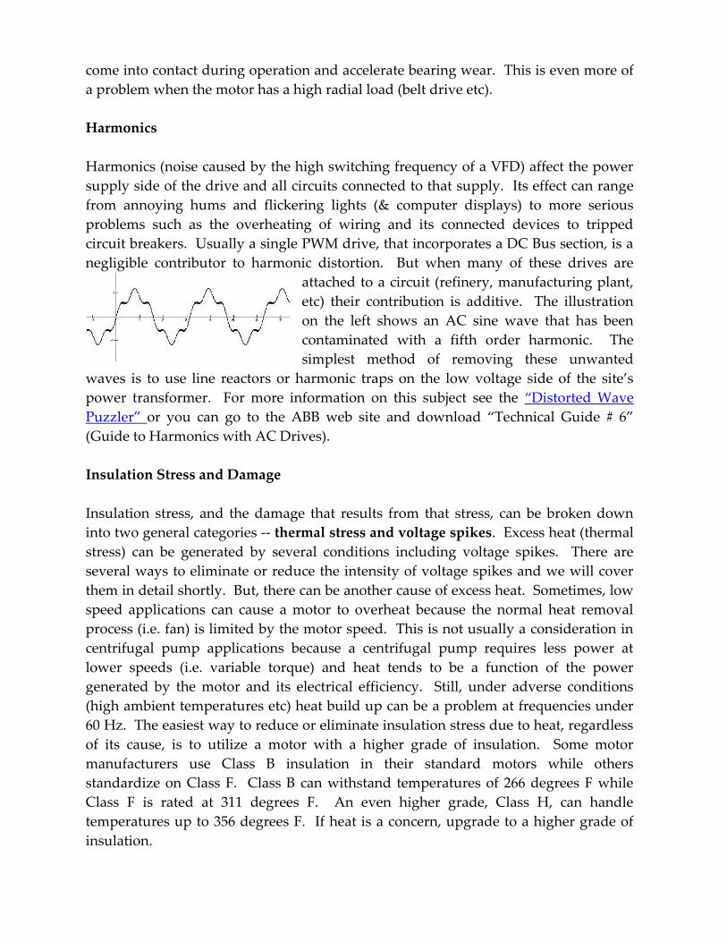
negligible contributor to harmonic distortion. But when many of these drives are
attached to a circuit (refinery, manufacturing plant,
etc) their contribution is additive. The illustration
on the left shows an AC sine wave that has been
contaminated with a fifth order harmonic. The
simplest method of removing these unwanted
waves is to use line reactors or harmonic traps on the low voltage side of the site’s
power transformer. For more information on this subject see the “Distorted Wave
Puzzler” or you can go to the ABB web site and download “Technical Guide # 6”
(Guide to Harmonics with AC Drives).
Insulation Stress and Damage
Insulation stress, and the damage that results from that stress, can be broken down
into two general categories -- thermal stress and voltage spikes. Excess heat (thermal
stress) can be generated by several conditions including voltage spikes. There are
several ways to eliminate or reduce the intensity of voltage spikes and we will cover
them in detail shortly. But, there can be another cause of excess heat. Sometimes, low
speed applications can cause a motor to overheat because the normal heat removal
process (i.e. fan) is limited by the motor speed. This is not usually a consideration in
centrifugal pump applications because a centrifugal pump requires less power at
lower speeds (i.e. variable torque) and heat tends to be a function of the power
generated by the motor and its electrical efficiency. Still, under adverse conditions
(high ambient temperatures etc) heat build up can be a problem at frequencies under
60 Hz. The easiest way to reduce or eliminate insulation stress due to heat, regardless
of its cause, is to utilize a motor with a higher grade of insulation. Some motor
manufacturers use Class B insulation in their standard motors while others
standardize on Class F. Class B can withstand temperatures of 266 degrees F while
Class F is rated at 311 degrees F. An even higher grade, Class H, can handle
temperatures up to 356 degrees F. If heat is a concern, upgrade to a higher grade of
insulation.
Voltage spikes present quite a different problem. Although they may cause an overall
rise in operating temperature, their main contribution to insulation stress is their
ability to cause a small breakdown (known as a partial discharge PD) in the air filled
voids that occur in any insulation system. Repeated PD breakdowns will eventually
destroy the insulation. Another phenomenon caused by voltage spikes is known as a
corona discharge (usually a slice of lime will fix this one). A corona discharge ionizes
the air between the windings and the highly reactive ions that are formed can cause
insulation to deteriorate over time. This type of discharge occurs more often in hot,
humid environments.
What exactly causes these voltage spikes to occur during VFD operation. Well, they
can be due one or any combination of three different conditions:
Overshoot occurs when the DC pulse “over shoots” the maximum peak voltage
required by the motor. At the beginning of the pulse, voltage rises rapidly and
typically exceeds peak voltage before it settles down. Voltage overshoot can be 10-
20% greater than peak voltage but usually does not cause a problem by itself because
standard motor insulation is designed to handle up to 600V continuously.
Reflected Voltage occurs when a wave travels down a transmission line and is
reflected back and combines with the incoming wave (similar to ripples traveling
across a pond that strike a barrier). This reflection is caused by the difference between
the line and load (motor) impedance. If they are the same there is no reflection. If
there is a large difference, the amplitude of the reflected wave will approach that of
the original wave. Under certain conditions (rise time and travel time are not
discussed here) the reflected wave will combine with the original wave resulting in a
much higher voltage at the motor.
Ringing is the result of the capacitance and inductance of the cable, motor, and the
output circuit of the VFD. Together they can create a resonant circuit that can cause
the edges of the voltage circuit to assume an undampened ringing waveform. When
combined with reflection, ringing can result in voltage peaks at the motor of two to
three times the normal peak voltage.
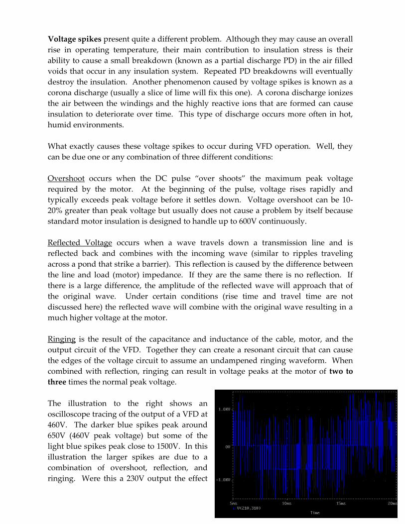
The illustration to the right shows an
oscilloscope tracing of the output of a VFD at
460V. The darker blue spikes peak around
650V (460V peak voltage) but some of the
light blue spikes peak close to 1500V. In this
illustration the larger spikes are due to a
combination of overshoot, reflection, and
ringing. Were this a 230V output the effect

would be the same but, the peak voltage of the spikes probably would not exceed
900V. The statement is important because, as you will see a little later, voltage spikes
are not usually a problem in 230V applications if certain rules are followed.
Eliminating the voltage spikes seen in the
previous illustration can be as easy as
following NEMA cable length guide lines or
it could be more complex and require the
installation of load reactors or dv/dt filters
between the motor and the drive. The
illustration to the left shows the same 460V
VFD output after appropriate corrective
action (cable length, filters etc) was taken.
As you can see the 1500V spikes have been
reduced to nearly that of the 650V pulses.
The application of line reactors and dv/dt filters is a topic for a future discussion. In
most cases, they will not be required if we select the proper motor and follow the
recommended cable length guidelines. For more information on the application of
reactors and filters, see the “Mumbo-Jumbo Puzzler” or go to the ABB website and
download Technical Guide # 102 (Effects of AC Drives on Motor Insulation).
Resonant Frequency
The resonant frequency or, the frequency at which an object undergoes natural
vibration, is often overlooked when applying a VFD to a pumping application. In the
VFD environment this is often referred to as the critical speed or critical frequency.
You have probably witnessed this phenomenon many times. Vehicles with manual
transmissions often exhibit greater vibration at certain engine speeds. Certain musical
tones, especially lower ones, will cause objects on a table to rattle even when the
volume is low. And, some of us are familiar with the vibrating wine glass that breaks
due to the pitch of the singers voice. (If you would like to see this in action click on the
Quick Time movie “Resonate Frequency” in the VFD section of my web site.)
The same is true of a rotating machine - - at some rotational speed or speeds, one or
more of its components will begin to vibrate. This is not a problem when a standard,
fixed speed pump is employed. If resonance occurred at its design speed, it would
have been detected and eliminated during the testing phase. When that same pump is
used in a variable speed application, however, it could, very well, exhibit vibration at
speeds above or below its nominal fixed speed.
It is difficult to predict whether a particular pump will exhibit resonance over the
speed range it encounters during variable frequency operation. As a rule of thumb,
frame mounted pumps are more likely to exhibit this form of vibration than are close
coupled units. Likewise, multistage pumps and those with elongated shafts also tend
to be more vulnerable. There is, however, a simple way of testing for resonance and
avoiding it, if it occurs. With the VFD in manual mode, simply scroll through each
frequency value from the lowest to the highest (for example 30 through 60 hertz). Let
the pump run at each frequency for five seconds or so. If a resonate frequency is
encountered, noticeable vibration will occur. You might also find that vibration may
not be limited to a single hertz, but occurs over a range (say 33 to 35 hertz). Once
these critical speeds or speed ranges have been determined, the drive can be
programmed to bypass them. Although the pump will still pass through these points,
it will not remain there long enough to cause vibration.
AC Motor Selection and Cabling
I mentioned earlier that voltage spikes do not usually present a problem in 230V VFD
applications. The reason this is true is that all NEMA standard motors use an
insulation that is designed to operate at 600V continuously and withstand intermittent
voltage spikes of 1000V (a new motor can often withstand spikes to 1200V). Even if a
spike were three times normal peak voltage (325V), it would still be within the 1000V
limit. The net result is that standard motors are well suited for operation in 230V VFD
applications as long as the drive and motor manufacturer’s cable length guidelines are
followed. Always consult the manufacturer if the cable between the drive and motor
will exceed 200 feet. If higher than normal ambient temperatures exist, you may want
to upgrade to a motor that uses Class F insulation but, “special” inverter duty
insulation is not required.
Unfortunately this is not always the case for 460V applications. Due to the high peak
voltage (650V), even relatively small spikes can exceed the 1000V limit of standard
motors. If the cable length between the VFD and a standard motor exceeds 25 feet, a
load reactor or dv/dt filter is always recommended. Always follow the manufacturers
cable length guidelines closely when using standard motors in 460V VFD applications.
One way to get around the use of a reactor or filter in many 460V applications is to use
a motor specifically designed for VFD applications. Special inverter duty motors
utilize insulation that is designed to accommodate spikes up to 1600V and has a
temperature rating of Class F or H. In some cases, these motors can be up to 300 feet
downstream of the drive and still not require reactors or filters. Again, always follow
the manufacturers cable length guide lines.
I will end this section with one final cautionary note. Avoid 460V operation when
using standard motors with a frame size of 180 or smaller (180 = 5 to 7.5 HP, 56 = 2 to 3
HP). The reason I say this is that these motors tend to be manufactured with price as
the major objective. The insulation system is not as robust as that of larger frame
motors and they have an inherently high impedance. Since these motors are usually
wound for 230/460V operation and therefore utilize 600V insulation they can be used,
safely in 230V VFD applications.
Variable Speed Applications
We will end our discussion of VFD’s with several pumping application examples.
Although there are many uses for VFD’s in the pumping environment, they usually
fall into three basic categories -- constant pressure, constant flow, and variable flow.
There are, of course, other ways to maintain these conditions (control valves for
example) but the VFD offers an extra bonus -- a significant reduction in power
consumption.
Constant pressure applications include those where pressure is maintained at some
desired point regardless of flow. Domestic and commercial booster systems are a
good example and usually employ a pressure transducer that controls the output
frequency of the VFD which, in turn, changes pump speed in order to keep pressure
constant.
The illustration at the top of the following page shows a simplex booster in a constant
pressure application. The 60 HZ design point is 150 GPM @ 120 ‘ TDH and requires 6.4
BHP. The two other curves represent 55 and 50 Hz operation. The red horizontal line
indicates the constant pressure required at various flow rates. At about 53 Hz the
pump can provide 100 gpm at the design head and at 50 Hz it can provide about 50
gpm. Therefore over a relatively small frequency range of 50 to 60 Hz the pump will
provide 50 to 150 gpm at 120’. Remember that the VFD provduces not only 50, 55, and
60 Hz pulses, but also each individual (and fractional) Hz in between. The result is a
significant savings in the power required at flows lower than design flow. The brake
BHP requirement at 53 Hz (100 gpm) drops to 3.7 or 58% of design point HP. And, at
50 Hz (50 gpm) it drops to 2.5 HP or just 39% of that at the design point .
Now, we could use a pressure reducing valve (PRV) to maintain a constant pressure of
120 feet as demand decreases and take advantage of the centrifugal pump’s reduced
power consumption as its flow moves towards the left of the capacity curve. But, at the
100 gpm point on the 60 Hz curve the required BHP is 5.3. Even though flow is
reduced, the power required by a PRV application is 5.3 HP compared to 3.7 HP for
VFD control. At 50 gpm PRV control requires 4.3 HP or 72% more than the VFD. In a

constant pressure application, the VFD offers precise and flexible control plus an
increased power savings over mechanical constant pressure devices. Because
centrifugal pumps follow the laws of affinity, a relatively small change in frequency
(speed) can result in a substantial reduction in power.
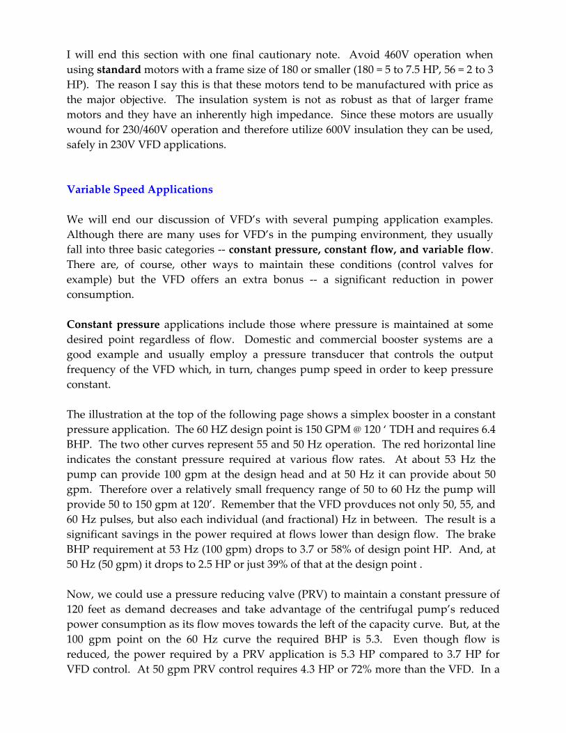
The illustration at the top of the following page is that of a Constant flow application. These
applications require flow to remain constant regardless of the back pressure the system may
encounter. A flow meter is usually employed to control VFD output and, in turn, motor
speed. Examples include maintaining levels in tanks at various elevations, manufacturing
processes, and the operation of nearby and remote irrigation zones. Each of the multiple
components served by these applications require similar flows but, differences in elevation,
back pressure, and pipe line friction may require different pressures to maintain those flows.
The system is designed for the highest pressure component of the application so that the VFD
can reduce motor speed for the lower pressure component and save energy in doing so.
Simplex VFD Constant Pressure Booster
0
20
40
60
80
100
120
140
160
180
200
0 25 50 75 100 125 150 175
Gallons Per Minute
T D H (ft)
60 hz
55 hz
50 hz
6.4 HP 3.7 HP 2.5 HP
4.3 HP
5.3 HP
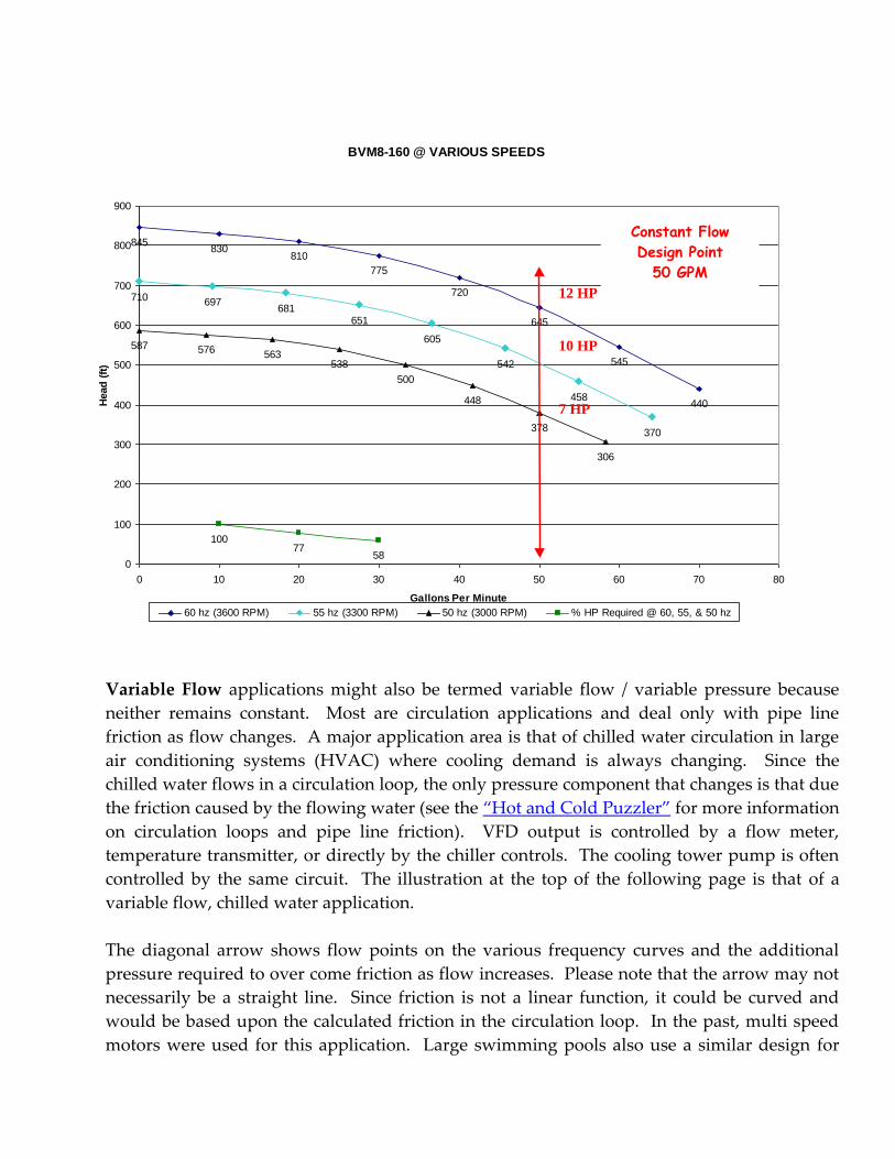
Variable Flow applications might also be termed variable flow / variable pressure because
neither remains constant. Most are circulation applications and deal only with pipe line
friction as flow changes. A major application area is that of chilled water circulation in large
air conditioning systems (HVAC) where cooling demand is always changing. Since the
chilled water flows in a circulation loop, the only pressure component that changes is that due
the friction caused by the flowing water (see the “Hot and Cold Puzzler” for more information
on circulation loops and pipe line friction). VFD output is controlled by a flow meter,
temperature transmitter, or directly by the chiller controls. The cooling tower pump is often
controlled by the same circuit. The illustration at the top of the following page is that of a
variable flow, chilled water application.
The diagonal arrow shows flow points on the various frequency curves and the additional
pressure required to over come friction as flow increases. Please note that the arrow may not
necessarily be a straight line. Since friction is not a linear function, it could be curved and
would be based upon the calculated friction in the circulation loop. In the past, multi speed
motors were used for this application. Large swimming pools also use a similar design for
BVM8-160 @ VARIOUS SPEEDS
845830
810
775
720
645
545
440
710 697681
651
605
542
458
370
587 576 563538
500
448
378
306
10077
580
100
200
300
400
500
600
700
800
900
0 10 20 30 40 50 60 70 80
Gallons Per Minute
Head
(ft
)
60 hz (3600 RPM) 55 hz (3300 RPM) 50 hz (3000 RPM) % HP Required @ 60, 55, & 50 hz
Constant Flow
Design Point
50 GPM
7 HP
10 HP
12 HP
circulation through a filter. Again, power savings is achieved as the flow is decreased by the
VFD.
A final advantage, available to any VFD application, is the Soft Start/Stop option. This option
allows the pump and motor to be started at a lower frequency ( say 30 HZ ) and then
“ramped” up to run speed over a period of a second or more. The result is a significant
reduction in the starting current required by the motor. Some utilities require that motors
over a certain HP undergo a soft start. With the VFD, its just part of the package. In addition
to a lower inrush current, mechanical stress on the motor and pump are also greatly reduced.
In a normal “across the line” start, the motor rotor and pump rotating element go from
motionless to the motor’s rated RPM in about one second! And, soft start/stop virtually
eliminates water hammer in almost any pumping system.
I hope that this short introduction has given you a better understanding of the Variable
Frequency Drive, its operation, and its application to centrifugal pumps. If you decide that
you would like to learn more, I suggest that you go to the ABB web site
www.abb.com/motors&drives and download the technical publications located there. They are
extremely well written and cover many areas of VFD operation and application ( including a
cable length guide) . All are in PDF format. If you have questions or suggestions email me at
0
10
20
30
40
50
60
70
80
90
100
0 100 200 300 400 500 600 700 800
Head
(ft
)
Gallons Per Minute
B3ZPMS @ Various Speeds
60Hz 50Hz 40Hz
Variable
12
6
3

Joe Evans
June 2003