Embed Size (px)
Citation preview
1
VARIABLE FREQUENCY DRIVE
Instruction Manual
CA Series This is brief instruction manual for basic review, for detail version please download in ※
www.tpg‐tw.com for further study.

2
Thank you for using TPG CA series drive. For proper operations and safety purposes, please do read and follow specific instructions contained in this manual before using the product.
SAFETY PRECAUTION A. Don’t touch the inverter circuit in 5 mins after the power LED indicator off, due to the
remain electricity still left in the body of inverter. Make sure to be off the power, while installation or taking‐off this drive.
B. Don’t put any object into this drive or touch any PC board of this C. The earth wire must be connected with ground surely. D. Don’t touch the heat sink to avoid any burning, due to high E. temperature over 70
degree C. F: Don’t use single phase motor to matching this drive. G. Don’t connect U.V.W. points of this drive to input power. The environment conditions:
Atmosphere Non‐corrosive or non‐conductive, or non‐explosive gas or liquid, and non‐dusty
Surrounding temperature
‐10°C (14°F) ~ +50°C (122°F) (Non‐freezing and non‐condensing)
Storage temperature
‐20°C (‐4°F) ~ +60°C (149°F)
Relative humidity 90% RH or less (No‐condensing atmosphere) Vibration Less than 5.9m/sec² (0.6G) Altitude Less than 1000m (3280 ft.)
Features 1. With the temperature managemen 2. Allow RS‐485 communication interface control (Modbus RTU communication protocol). 3. Special function key(SPEC):
Programmable function key for forward/reverse running, jog speed, selection of primary/secondary frequency command…etc.
4. The switching frequency can be adjust between 800Hz ~ 16kHz. 5. Provide 8 sets of monitor displays(three of displays can be defined as another extra
displays). 6. Provide PTC sensor setting functions for preventing the motor from overheating. 7. 6 sets of fault records:
Record 4 types of information under fault condition, respectively. (fault code, output current, DC bus voltage, output frequency)

3
Chapter 1 Cautions Before Installation The product has passed the strictest quality test before shipped out from the factory.
However, the product might possibly sustain minor damages due to the impact, shaking, vibration, and other factors during the transportation. Please make sure to verify the following items after receiving this product. If the product verification finds anything abnormal, please contact the agent immediately for the further assistance. 1. Check up the appearance of the drive for any paint chipped off, smearing, deformation
of shape, etc. 2. Check up the nameplate (as below figure) of the drive to verify the product descriptions
with the order specification. 1‐1 Nameplate
1‐2 Standard Specifications
Model name CA CA‐201A CA‐202A Maximum applicable motor (W) 125 200 Rated output capability (VA) 400 600 Rated output current (A) 0.9 1.5 Rated output voltage (V) Three‐phase 200~240V Range of output frequency (Hz) 0.1~400Hz Power source (ψ, V, Hz) 1Ø, 200~240V , 50 / 60Hz Input current (A) 1.7 3 Permissible AC power source fluctuation
176V~264V 50/60Hz /±5%
Overload protection 150% of drive rated output current for 1 min. Cooling method Nature cooling Protective structure IP20 Weight / Mass(kg) 384g

4
10cm
5cm
10cm
5cm
Chapter 2 Installation and Confirmation 2‐1 Installation
For the safe operation of the drive, please be cautious to the environmental conditions where the drive is going to be installed.
1. Cleaning of Environment: The installed location of drive must consider the ventilation, cleanliness and moisture.
2. Due to the heat dissipating requirement during the drive operation, the drive must keep enough space for heat dissipation
3. Surrounding temperature ‐10℃~+45℃(14℉~122℉) 4. Due to the heat dissipating requirement during the drive operation, the drive must keep
enough space for heat dissipation. Please keep the least clearance space when installation. (shown as below figure):
2‐2 Description of Terminals 2‐2‐1 Wiring Diagram
Modbus Port
Grounding
Single‐phasepower source
Three‐phaseMotor
5
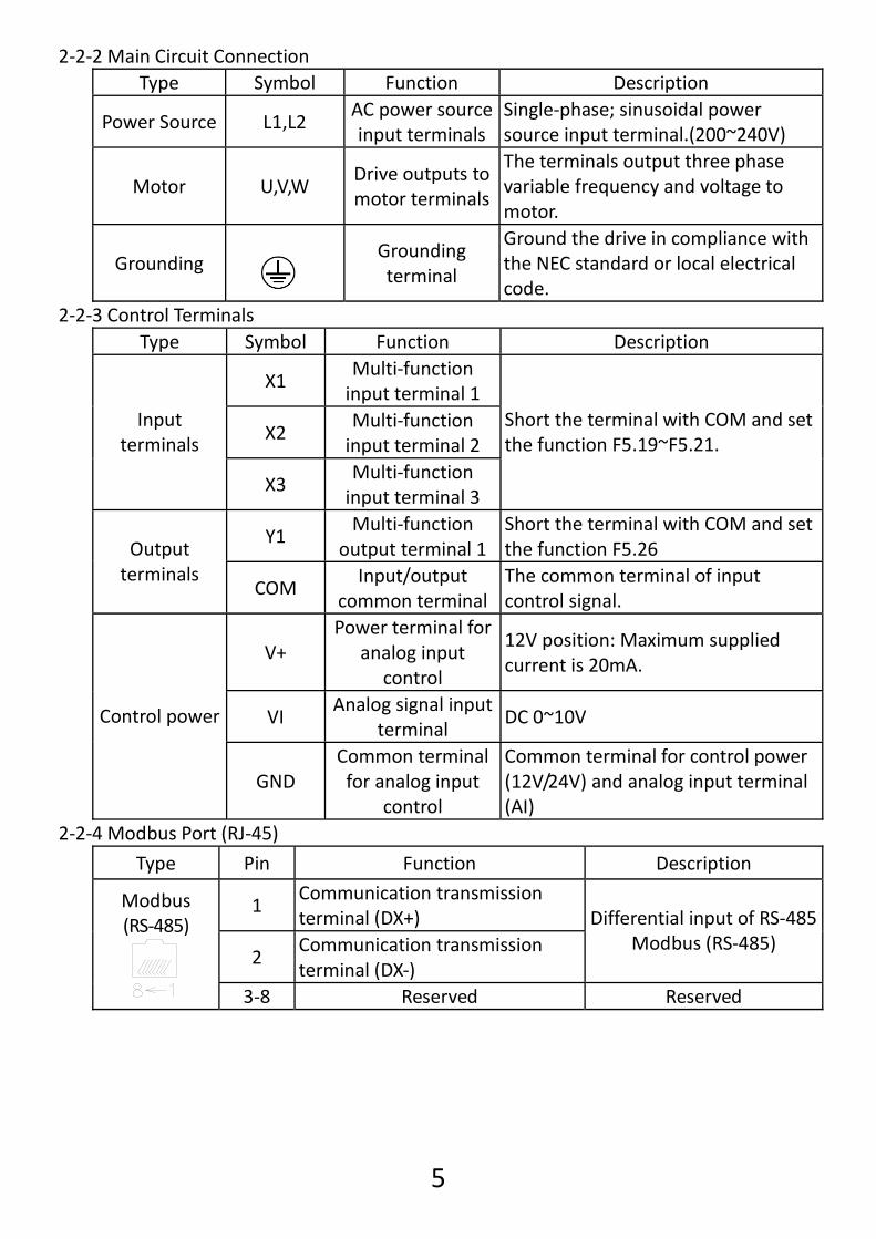
2‐2‐2 Main Circuit Connection Type Symbol Function Description
Power Source L1,L2 AC power source input terminals
Single‐phase; sinusoidal power source input terminal.(200~240V)
Motor U,V,W Drive outputs to motor terminals
The terminals output three phase variable frequency and voltage to motor.
Grounding
Grounding terminal
Ground the drive in compliance with the NEC standard or local electrical code.
2‐2‐3 Control Terminals Type Symbol Function Description
X1 Multi‐function input terminal 1
X2 Multi‐function input terminal 2
Input terminals
X3 Multi‐function input terminal 3
Short the terminal with COM and set the function F5.19~F5.21.
Y1 Multi‐function
output terminal 1Short the terminal with COM and set the function F5.26 Output
terminals COM
Input/output common terminal
The common terminal of input control signal.
V+ Power terminal for
analog input control
12V position: Maximum supplied current is 20mA.
VI Analog signal input
terminal DC 0~10V Control power
GND Common terminal for analog input
control
Common terminal for control power (12V/24V) and analog input terminal (AI)
2‐2‐4 Modbus Port (RJ‐45)
Type Pin Function Description
1 Communication transmission terminal (DX+)
2 Communication transmission terminal (DX‐)
Differential input of RS‐485 Modbus (RS‐485)
Modbus (RS‐485)
3‐8 Reserved Reserved
6
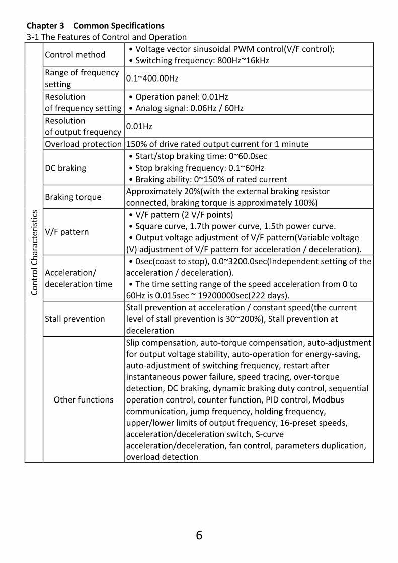
Chapter 3 Common Specifications 3‐1 The Features of Control and Operation
Control method ․Voltage vector sinusoidal PWM control(V/F control); ․Switching frequency: 800Hz~16kHz
Range of frequency setting
0.1~400.00Hz
Resolution of frequency setting
․Operation panel: 0.01Hz ․Analog signal: 0.06Hz / 60Hz
Resolution of output frequency
0.01Hz
Overload protection 150% of drive rated output current for 1 minute
DC braking ․Start/stop braking time: 0~60.0sec ․Stop braking frequency: 0.1~60Hz ․Braking ability: 0~150% of rated current
Braking torque Approximately 20%(with the external braking resistor connected, braking torque is approximately 100%)
V/F pattern
․V/F pattern (2 V/F points) ․Square curve, 1.7th power curve, 1.5th power curve. ․Output voltage adjustment of V/F pattern(Variable voltage (V) adjustment of V/F pattern for acceleration / deceleration).
Acceleration/ deceleration time
․0sec(coast to stop), 0.0~3200.0sec(Independent setting of the acceleration / deceleration). ․The time setting range of the speed acceleration from 0 to 60Hz is 0.015sec ~ 19200000sec(222 days).
Stall prevention Stall prevention at acceleration / constant speed(the current level of stall prevention is 30~200%), Stall prevention at deceleration
Control Characteristics
Other functions
Slip compensation, auto‐torque compensation, auto‐adjustment for output voltage stability, auto‐operation for energy‐saving, auto‐adjustment of switching frequency, restart after instantaneous power failure, speed tracing, over‐torque detection, DC braking, dynamic braking duty control, sequential operation control, counter function, PID control, Modbus communication, jump frequency, holding frequency, upper/lower limits of output frequency, 16‐preset speeds, acceleration/deceleration switch, S‐curve acceleration/deceleration, fan control, parameters duplication, overload detection
7
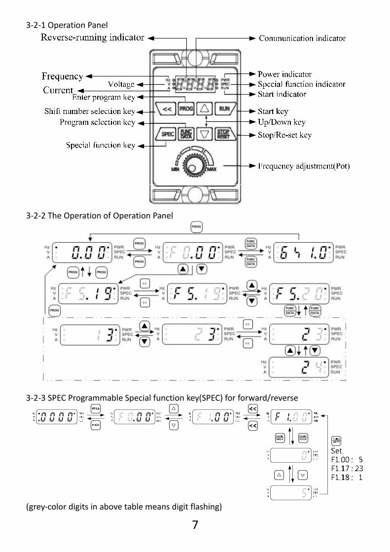
3‐2‐1 Operation Panel
3‐2‐2 The Operation of Operation Panel
3‐2‐3 SPEC Programmable Special function key(SPEC) for forward/reverse
(grey‐color digits in above table means digit flashing)
8
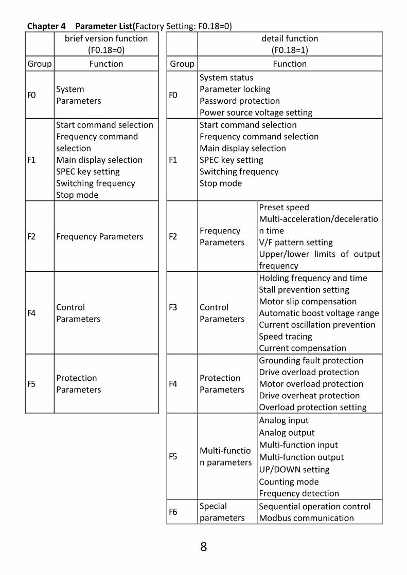
Chapter 4 Parameter List(Factory Setting: F0.18=0)
brief version function
(F0.18=0) detail function
(F0.18=1) Group Function Group Function
F0 System Parameters
F0
System status Parameter locking Password protection Power source voltage setting
F1
Start command selection Frequency command selection Main display selection SPEC key setting Switching frequency Stop mode
F1
Start command selection Frequency command selection Main display selection SPEC key setting Switching frequency Stop mode
F2 Frequency Parameters
F2 Frequency Parameters
Preset speed Multi‐acceleration/deceleration time V/F pattern setting Upper/lower limits of output frequency
F4 Control Parameters
F3
Control Parameters
Holding frequency and time Stall prevention setting Motor slip compensation Automatic boost voltage rangeCurrent oscillation preventionSpeed tracing Current compensation
F5 Protection Parameters
F4 Protection Parameters
Grounding fault protection Drive overload protection Motor overload protection Drive overheat protection Overload protection setting
F5 Multi‐function parameters
Analog input Analog output Multi‐function input Multi‐function output UP/DOWN setting Counting mode Frequency detection
F6
Special parameters
Sequential operation control Modbus communication
9
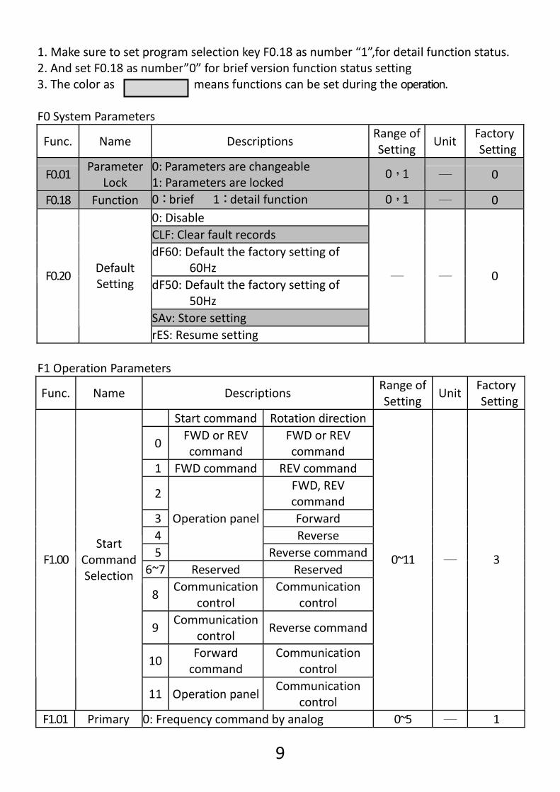
1. Make sure to set program selection key F0.18 as number “1”,for detail function status. 2. And set F0.18 as number”0” for brief version function status setting 3. The color as means functions can be set during the operation. F0 System Parameters
Func. Name Descriptions Range of Setting
Unit Factory Setting
F0.01 Parameter
Lock 0: Parameters are changeable 1: Parameters are locked
0,1 ─ 0
F0.18 Function 0:brief 1:detail function 0,1 ─ 0 0: Disable CLF: Clear fault records dF60: Default the factory setting of
60Hz dF50: Default the factory setting of
50Hz SAv: Store setting
F0.20 Default Setting
rES: Resume setting
─ ─ 0
F1 Operation Parameters
Func. Name Descriptions Range of Setting
Unit Factory Setting
Start command Rotation direction
0 FWD or REV command
FWD or REV command
1 FWD command REV command
2 FWD, REV command
3 Forward 4 Reverse 5
Operation panel
Reverse command6~7 Reserved Reserved
8 Communication
control Communication
control
9 Communication
control Reverse command
10 Forward command
Communication control
F1.00 Start
Command Selection
11 Operation panelCommunication
control
0~11 ─ 3
F1.01 Primary 0: Frequency command by analog 0~5 ─ 1
10
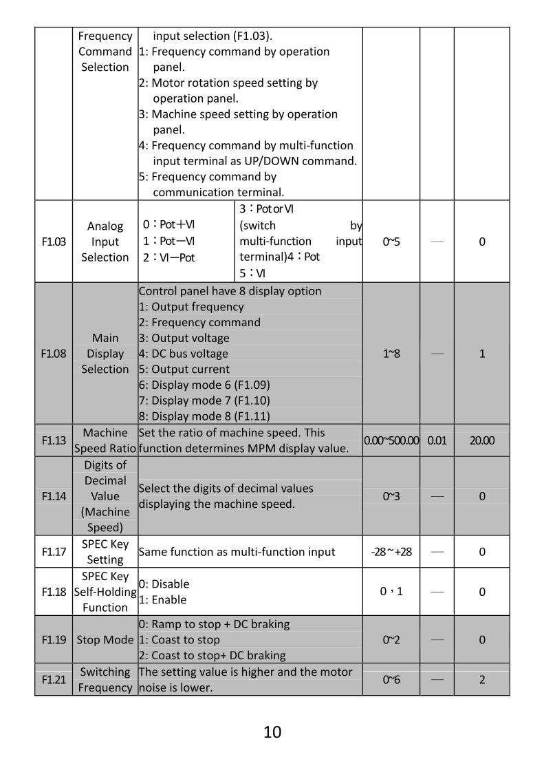
Frequency Command Selection
input selection (F1.03). 1: Frequency command by operation
panel. 2: Motor rotation speed setting by
operation panel. 3: Machine speed setting by operation
panel. 4: Frequency command by multi‐function
input terminal as UP/DOWN command.5: Frequency command by
communication terminal.
F1.03 Analog Input
Selection
0:Pot+VI 1:Pot-VI 2:VI-Pot
3:Pot or VI (switch by multi‐function input terminal)4:Pot 5:VI
0~5 ─ 0
F1.08 Main Display Selection
Control panel have 8 display option 1: Output frequency 2: Frequency command 3: Output voltage 4: DC bus voltage 5: Output current 6: Display mode 6 (F1.09) 7: Display mode 7 (F1.10) 8: Display mode 8 (F1.11)
1~8 ─ 1
F1.13 Machine
Speed Ratio Set the ratio of machine speed. This function determines MPM display value.
0.00~500.00 0.01 20.00
F1.14
Digits of Decimal Value
(Machine Speed)
Select the digits of decimal values displaying the machine speed.
0~3 ─ 0
F1.17 SPEC Key Setting
Same function as multi‐function input ‐28 ~ +28 ─ 0
F1.18 SPEC Key
Self‐Holding Function
0: Disable 1: Enable
0,1 ─ 0
F1.19 Stop Mode 0: Ramp to stop + DC braking 1: Coast to stop 2: Coast to stop+ DC braking
0~2 ─ 0
F1.21 Switching Frequency
The setting value is higher and the motor noise is lower.
0~6 ─ 2

11
F2 Frequency Parameters
Func. Name Descriptions Range of Setting
Unit Factory Setting
Jog Speed
Multi‐speedlevel 3
command
Multi‐speedlevel 2
command
Multi‐speedlevel 1
command
50.00 *Note 1
F2.00
Primary Speed (Preset Speed 1) OFF OFF OFF OFF
0.00~400.00 0.01Hz60.00
*Note 2F2.16 Jog Speed Jog speed 0.00~400.00 0.01Hz 6.00
F2.18 Primary
Acceleration Time
The acceleration time of primary speed, preset speed 5~8, and jog speed.
0.0~3200.0 0.1sec 5.0
F2.19 Primary
Deceleration Time
The deceleration time of primary speed, preset speed 5~8, and jog speed.
0.0~3200.0 0.1sec 5.0
50.00 *Note 1
F2.32 Maximum Output
Frequency Maximum output frequency of drive 0.1~400.0 0.1Hz
60.00 *Note 2
F2.34 Starting Voltage
The voltage corresponds to the output starting frequency.
0.1~50.0 0.1V 8.0
50.00 *Note 1
F2.35 Base
Frequency The frequency corresponds to the base voltage in V/F pattern.
0.1~400.0 0.1Hz60.00
*Note 2
F2.36 Base Voltage The voltage corresponds to the base frequency in V/F pattern.
0.1~255.0 0.1V 220.0
F2.47 Frequency Upper Limit
The upper limit of output frequency (1.00=maximum output frequency)
0.00~1.00 0.01 1.00
F2.48 Frequency Lower Limit
The lower limit of output frequency (1.00=maximum output frequency)
0.00~1.00 0.01 0.00

12
F4 Protection Parameters
Func. Name Descriptions Range of Setting
Unit Factory Setting
F4.08 Motor Rated
Current Current setting according to the motor rated current.
10%~150% of drive rated current
0.1A
According to the rated current of motor
F5 Multi‐function Parameters
Func. Name Descriptions Range of Setting
Factory Setting
F5.19 Multi‐function Input Terminal
X1
‐28 ~ +28
22
F5.20 Multi‐function Input Terminal
X2
‐28 ~ +28
23
F5.21 Multi‐function Input Terminal
X3
0: Disable ±1: Jog command ±2: Secondary accel/decel command
switching ±3: Multi‐speed level 1
command ±4: Multi‐speed level 2
command ±5: Multi‐speed level 3
command ±6: Multi‐speed level 4
command ±7: Reset command ±8: External fault
command(EF) ±9: Interruption of
output command(bb)±10: Coast to stop
command(Fr) ±11: Speed search from
the maximum frequency
±12: Speed search from the frequency
±13: Holding command ±14: UP command
±14: UP command ±15: DOWN
command ±16: Clean
UP/DOWN frequency command
±17: UP/DOWN command enter key
±18: Analog input source selection (Pot knob/AI)
±19: Primary and secondary frequency command option
±20: Start command of sequential operation control
±21: Pause command of sequential operation control
±22: Forward command
±23: Reverse command
±24: Stop command with 3‐wire
start/stop circuit
‐28 ~ +28
1
13
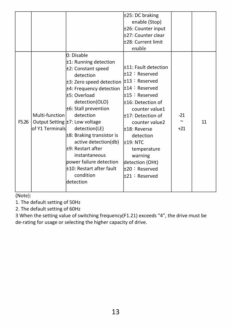
±25: DC braking enable (Stop)
±26: Counter input ±27: Counter clear ±28: Current limit
enable
F5.26 Multi‐function Output Setting of Y1 Terminals
0: Disable ±1: Running detection ±2: Constant speed
detection ±3: Zero speed detection±4: Frequency detection±5: Overload
detection(OLO) ±6: Stall prevention
detection ±7: Low voltage
detection(LE) ±8: Braking transistor is
active detection(db)±9: Restart after
instantaneous power failure detection ±10: Restart after fault
condition detection
±11: Fault detection ±12:Reserved ±13:Reserved ±14:Reserved ±15:Reserved ±16: Detection of
counter value1 ±17: Detection of
counter value2 ±18: Reverse
detection ±19: NTC
temperature warning
detection (OHt) ±20:Reserved ±21:Reserved
‐21 ~ +21
11
(Note): 1. The default setting of 50Hz 2. The default setting of 60Hz 3 When the setting value of switching frequency(F1.21) exceeds “4”, the drive must be de‐rating for usage or selecting the higher capacity of drive.

14
Chapter 5 Operation Procedures and Fault Protection Fault Displays Error Trip Messages of Drive
Display Description Display Description
IGBT module error
PID feedback signal error
Grounding fault
A/D converter error
Drive over current
External fault
Motor overload
Keypad interruption during copy
Drive overload
EEPROM error
Drive current limit
Internal memory error
Braking transistor overload
Internal memory error
System overload
Thermal sensor fault
Over voltage
Drive overheat
Under voltage during operation
Motor overheat
Warning Messages of Drive
Display Description Display Description
System overload
Motor overheat
Power source over voltage
Drive output interruption
Braking transistor is active
Coast to stop
Power source under voltage
Forwad/reverse command input simultaneously
Drive overheat
Modbus communication
overtime

15
Chapter 6 Outline Dimension Drawings Overall Dimensions of Drive
1. Removable bracket frame 2. Fixing screws
Unit:mm
M4 screws

16
Attachment A. Thanks for your kindly purchase TPG products, CA series AC motor drive. For thepurpose to offer the full complete set service,TPG also produces all kinds motors,which can be matching with above inverters. For the detail spec. & information,please contact our agent or visit our website www.tpg-tw.com.
A1. Gear Motor
A3. Worm gear speed reducer
A2. Mighty tiny series (Motor)
A4. Mighty tiny series(Gear Motor)
Thanks much for your choice TPG products and TPGwill supply a period of 12 months warranty from date oforiginal purchase. TPG will repair or replace withoutcharge devices which our examination proves to bedefective in material or workmanship. This warranty is valid if the unit has not been tampered with byunauthorized persons, misused, abused, or improperlyinstalled and has been used in accordance with theinstructions and or rating supplied. The foregoing in lieu
of any other warranty or guarantee, expressed or implied, and we are notresponsible for any expense (including installation and removal), inconvenience, orconsequential damage caused by items of our manufacture or sale. Please sendback your defected products to any TPG branch office or distributors available asbelow showed. IMPORTANT-fill out and mail this card. *Note: if you purchased more than(1) unit, fillout 1 card only and indicate the series number.
Pur. By:____________ Pur. Date:_________ Address:__________________________ Tel No.:___________________________ Contact name:___________Pur. From:_______
Product Name:____________Q’ty:_________ Model No.:_________________________ Series No.:_________________________
Warranty Card