Embed Size (px)
Citation preview

Variable Speed Drive
Hardware and Installation Manual


Variable Speed Drive
Hardware and Installation Manual
Edition: October 2012
SD70MTHW01CI Rev. C

SD700 SERIES POWER ELECTRONICS
2
POWER ELECTRONICS SD700 SERIES
3
SAFETY SYMBOLS
Always follow safety instructions to prevent accidents and potential hazards from occurring.
Edition October 2012 This publication could present technical imprecision or misprints. The information here included will be periodically modified and updated, and all those modifications will be incorporated in later editions. To consult the most updated information of this product you might access through our website www.power-electronics.com where the latest version of this manual can be downloaded.
WARNING
This symbol means improper operation may results in serious personal injury or death.
CAUTION
Identifies shock hazards under certain conditions. Particular attention should be given because dangerous voltage may be present. Maintenance operation should be done by qualified personnel.
Identifies potential hazards under certain conditions. Read the message and follow the instructions carefully.
Identifies shock hazards under certain conditions. Particular attention should be given because dangerous voltage may be present.

SD700 SERIES POWER ELECTRONICS
4
Revisions
Date Revision Description
08 / 01 / 2009 A First edition 23 / 11 / 2010 B Code description updating. Ratings at 440VAC. Misprinting errors. 08 / 10 / 2012 C Transportation. EMC installation requirements. Installation
recommendations. STO board safety function. ATEX. Multipulse drive connection. CE marking.
POWER ELECTRONICS SD700 SERIES
INDEX 5
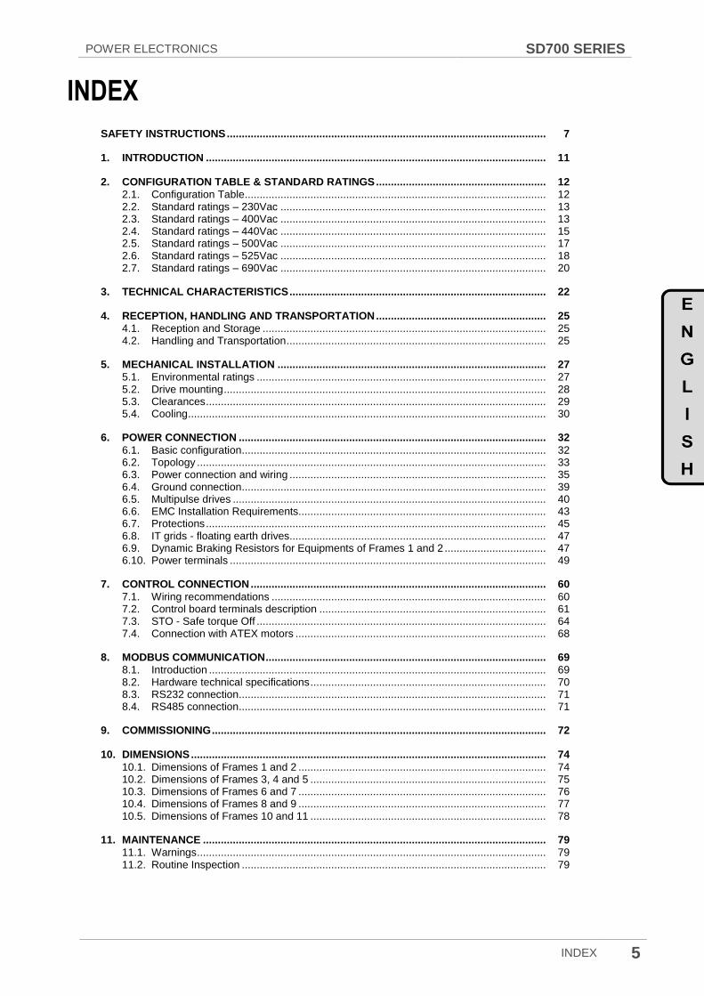
INDEX
SAFETY INSTRUCTIONS ........................................................................................................... 7
1. INTRODUCTION .................................................................................................................. 11
2. CONFIGURATION TABLE & STANDARD RATINGS ......................................................... 12
2.1. Configuration Table ..................................................................................................... 12 2.2. Standard ratings – 230Vac ......................................................................................... 13 2.3. Standard ratings – 400Vac ......................................................................................... 13 2.4. Standard ratings – 440Vac ......................................................................................... 15 2.5. Standard ratings – 500Vac ......................................................................................... 17 2.6. Standard ratings – 525Vac ......................................................................................... 18 2.7. Standard ratings – 690Vac ......................................................................................... 20
3. TECHNICAL CHARACTERISTICS ...................................................................................... 22
4. RECEPTION, HANDLING AND TRANSPORTATION ......................................................... 25
4.1. Reception and Storage ............................................................................................... 25 4.2. Handling and Transportation ....................................................................................... 25
5. MECHANICAL INSTALLATION .......................................................................................... 27
5.1. Environmental ratings ................................................................................................. 27 5.2. Drive mounting ............................................................................................................ 28 5.3. Clearances .................................................................................................................. 29 5.4. Cooling ........................................................................................................................ 30
6. POWER CONNECTION ....................................................................................................... 32
6.1. Basic configuration ...................................................................................................... 32 6.2. Topology ..................................................................................................................... 33 6.3. Power connection and wiring ...................................................................................... 35 6.4. Ground connection ...................................................................................................... 39 6.5. Multipulse drives ......................................................................................................... 40 6.6. EMC Installation Requirements................................................................................... 43 6.7. Protections .................................................................................................................. 45 6.8. IT grids - floating earth drives...................................................................................... 47 6.9. Dynamic Braking Resistors for Equipments of Frames 1 and 2 .................................. 47 6.10. Power terminals .......................................................................................................... 49
7. CONTROL CONNECTION ................................................................................................... 60
7.1. Wiring recommendations ............................................................................................ 60 7.2. Control board terminals description ............................................................................ 61 7.3. STO - Safe torque Off ................................................................................................. 64 7.4. Connection with ATEX motors .................................................................................... 68
8. MODBUS COMMUNICATION .............................................................................................. 69
8.1. Introduction ................................................................................................................. 69 8.2. Hardware technical specifications ............................................................................... 70 8.3. RS232 connection ....................................................................................................... 71 8.4. RS485 connection ....................................................................................................... 71
9. COMMISSIONING ................................................................................................................ 72
10. DIMENSIONS ....................................................................................................................... 74
10.1. Dimensions of Frames 1 and 2 ................................................................................... 74 10.2. Dimensions of Frames 3, 4 and 5 ............................................................................... 75 10.3. Dimensions of Frames 6 and 7 ................................................................................... 76 10.4. Dimensions of Frames 8 and 9 ................................................................................... 77 10.5. Dimensions of Frames 10 and 11 ............................................................................... 78
11. MAINTENANCE ................................................................................................................... 79
11.1. Warnings ..................................................................................................................... 79 11.2. Routine Inspection ...................................................................................................... 79
SD700 SERIES POWER ELECTRONICS
6 INDEX
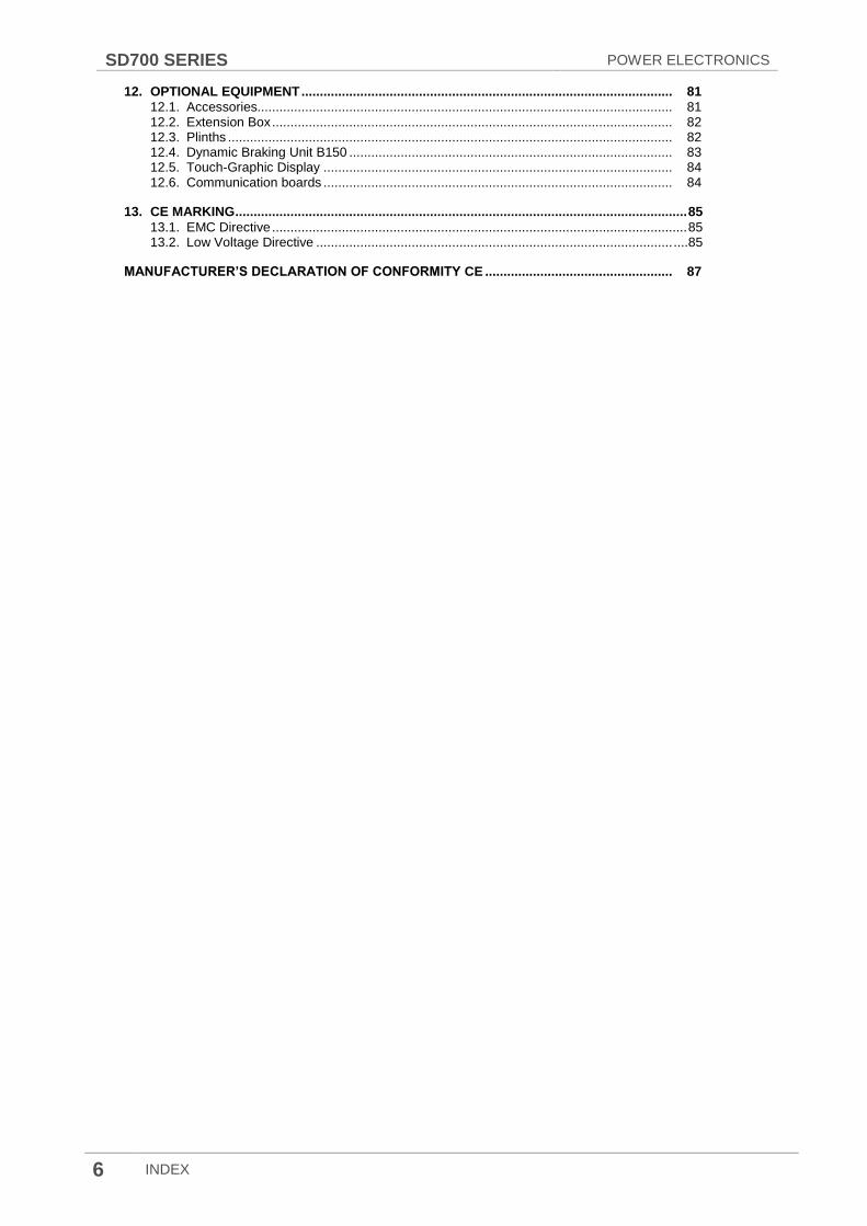
12. OPTIONAL EQUIPMENT ..................................................................................................... 81
12.1. Accessories................................................................................................................. 81 12.2. Extension Box ............................................................................................................. 82 12.3. Plinths ......................................................................................................................... 82 12.4. Dynamic Braking Unit B150 ........................................................................................ 83 12.5. Touch-Graphic Display ............................................................................................... 84 12.6. Communication boards ............................................................................................... 84
13. CE MARKING ........................................................................................................................... 85
13.1. EMC Directive ................................................................................................................. 85 13.2. Low Voltage Directive ................................................................................................. ....85
MANUFACTURER’S DECLARATION OF CONFORMITY CE ................................................... 87

POWER ELECTRONICS SD700 SERIES
SAFETY INSTRUCTIONS 7
SAFETY INSTRUCTIONS
IMPORTANT!
Read this manual carefully to maximise the performance of this product and to ensure its safe use and installation.
Power Electronics accepts no responsibility or liability for any damage resulting from inappropriate use of the equipment.
In this manual, safety messages are classified as follows:
WARNING
Do not remove the metal cover while the power is applied or the unit is in operation.
Otherwise electric shock could occur.
Do not run the drive with the front cover removed.
Otherwise, you may get an electric shock due to the high voltage terminals or exposure of charged capacitors.
The drive does not remove the voltage from the input busbars of the drive. Before working on the drive, isolate the whole drive from the supply.
Do not remove the cover except for periodic inspections or wiring, even if the input power is not applied.
Otherwise, you may access to the charged circuits and may get an electric shock.
Wiring and periodic inspections should be performed at least 10 minutes after disconnecting the
input power. To remove the front cover check that the DC Link red LED is off, then remove the
terminals metallic cover and check with a multimeter the following measures:
Measure between the output power busbars U, V, W and the cabinet and check that the
voltage is around 0V.
Measure that the DC link terminals +, - and chassis voltage are below 30VDC.
Otherwise, you may get an electric shock.
Operate the switches with dry hands. Otherwise, you may get an electric shock.
Do not use cables with damaged insulation. Otherwise, you may get an electric shock.
Do not subject the cables to abrasions, excessive stress, heavy loads or pinching. Otherwise, you
may get an electric shock.
Do not make any insulation or voltage withstand tests on the motor with the drive connected.

SD700 SERIES POWER ELECTRONICS
8 SAFETY INSTRUCTIONS
CAUTION
Install the drive on a non-flammable surface. Do not place flammable material nearby. Otherwise
fire could occur.
Disconnect the input power if the drive is damaged. Otherwise, it could result in a secondary accident
or fire.
After stopping the drive, it will remain hot for a couple of minutes. Touching hot parts may result in
skin burns.
Do not apply power to a damaged drive or to a drive with parts missing even if the installation is complete. Otherwise, you may get an electric shock.
It is not permitted to weld the cabinet; this can damage the electronic sensitive equipment inside.
Do not allow lint, paper, wood chips, dust, metallic chips or other foreign matter into the drive.
Otherwise fire or accident could occur.
WARNINGS
RECEPTION
The SD700 are carefully tested and perfectly packed before delivering.
In the event of transport damage, please ensure that you notify the transport agency and POWER ELECTRONICS: 902 40 20 70 (International +34 96 136 65 57) or your nearest agent, within 24hrs from receipt of the goods.
UNPACKING
Make sure model and serial number of the variable speed drive are the same on the box, delivery note and unit.
Each variable speed drive is delivered with Hardware and Software technical manuals.
RECYCLING
Packing of the equipments should be recycled. For this, it is necessary to separate different materials included (plastic, paper, cardboard, wood ...) and deposit them on proper banks.
Waste products of electric and electronic devices should be selectively collected for your correct recycling company.
ELECTROMAGNETIC COMPATIBILITY (EMC)
The drive is intended to be used in industrial environment (Second Environment), it achieve compliance with C3 category defined in IEC/EN 61800-3 standard following the installation recommendation within this manual.
Select communication and control system according to the drive EMC environment. Otherwise, systems could suffer from interferences due to a low EMS level.
POWER ELECTRONICS SD700 SERIES
SAFETY INSTRUCTIONS 9
SAFETY
Before operating the drive, read this manual thoroughly to gain and understanding of the unit. If any doubt exists then please contact POWER ELECTRONICS, (902 40 20 70 / +34 96 136 65 57) or your nearest agent.
Wear safety glasses when operating the drive with power applied or the front cover is removed.
Handle and transport the drive following the recommendations within this manual.
Install the drive according to the instructions within this manual and the local regulations.
Do not place heavy objects on the drive.
Ensure that the drive is mounted vertically and keeping the minimum clearances distances.
Do not drop the drive or subject it to impact.
The SD700 drives contain static sensitive printed circuits boards. Use static safety procedures when handling these boards.
Avoid installing the drive in conditions that differ from those described in the Environmental Ratings section.
CONNECTION PRECAUTIONS
To ensure correct operation of the drive it is recommended to use a SCREENED CABLE for the control wiring.
The motor cable should comply with the requirements within this manual. Due to increased leakage capacitance between conductors, external ground fault protection threshold value should be adjusted ad hoc.
Do not disconnect motor cables if input power supply remains connected.
The internal circuits of the SD700 Series will be damaged if the incoming power is connected and applied to output terminals (U, V, W).
Do not use power factor correction capacitors banks, surge suppressors, or RFI filters on the output side of the drive. Doing so may damage these components.
Always check whether the DC Link red LED is OFF before wiring terminals. The capacitors may hold high-voltage even after the input power is disconnected.
TRIAL RUN
Verify all parameters before operating the drive. Alteration of parameters may be required depending on application and load.
Always apply voltage and current signals to each terminal that are within levels indicated within this manual.
OPERATION PRECAUTIONS
When the Auto Restart function is enabled, keep clear of driven equipment, as the motor will restart suddenly after the fault reset.
The “STOP / RESET” key on the keypad is active only if the appropriate function setting has been made. Pushing this button the drive will NOT perform a safe stop. It is available STO optional board, which installed with a separate EMERGENCY pushbutton, will disconnect the power and will be unable to generate torque in the motor with high reliability.
If a fault is reset with the reference signal still active, the drive will unexpectedly restart. Verify that it is permissible for this to happen. Otherwise, it may lead to injury to people.
Do not modify or alter internal wiring and spare parts without Power Electronics supervision.
Before programming or operating the SD700 Series, initialise all parameters back to factory default values.

SD700 SERIES POWER ELECTRONICS
10 SAFETY INSTRUCTIONS
EARTH CONNECTION
Ground the drive and adjoining cabinets to ensure a safety operation and to reduce electromagnetic emission.
Connect the input PE terminal only to the dedicated PE terminal of the drive. Do not use the case or the chassis screw for grounding.
Ground the drive chassis through the dedicated and labelled terminals. Use appropriate conductors to comply with the local regulations. The ground conductor should be connected first and removed last.
Motor ground cable must be connected to the PE output terminal of the drive and not to the installation‟s ground. We recommend that the section of the ground conductor (PE) should be equal or greater than the active conductor (U, V, W).
If the user decides to use shielded motor cable, ensure a correct 360º shield bonding in both the drive cabinet and the motor terminal box.
HOW TO USE THIS MANUAL
Quick Guide
1- Make sure model and serial number of the drive are the same on the delivery note and unit. See Chapter 2.
2- Read carefully the safety instructions before installation, commissioning, operation and
maintenance of the drive. See safety instructions section.
3- For reception, handling and transportation see Chapter 4.
4- Before the mechanical installation, check the environmental ratings, drive configuration mounting
and clearances. See chapter 5.
5- Follow the mechanical installation instructions. See Chapter 5.
6- Before the electrical installations, check basic configuration and wiring recommendations, see
Chapter 6 and Chapter 7.
7- Follow the electrical installation instructions in Chapter 6 and Chapter 7.
8- For Modbus Communication hardware, see Chapter 8.
9- Follow the commissioning instructions in Chapter 9.
10- For preventive maintenance instructions, follow the recommendations in Chapter 11.

POWER ELECTRONICS SD700 SERIES
INTRODUCTION 11
1. INTRODUCTION
SD700 low voltage drives by Power Electronics is the most extensive product family with a power range from 1.5kW to 2000kW. It has been designed focused on maximum motor care, components durability and easy maintenance. SD700 portfolio is divided in 3 products series that comply with specific demands and standards in worldwide installations thanks to its own specific features: SD700, SD700KOMPAKT, SD700FREEMAQ (SD700FR & SD700FL).
SD700 SERIES is the core of the family, available from 1.5kW to 2000kW, a voltage range from 230VAC to 690VAC and available up to 24 pulses. IP20 and IP54 mechanical designs cover all general industry applications, making it the most flexible and extensive series.
The whole family integrates unique features such as low dV/dt, smart mechanical design and accurate control. It is divided in 11 frames to cover the whole power range.
Figure 1.1 SD700 Series
SD700 products provide high efficiency, maximum control, functional safety, durability, easy commissioning and easy maintenance for the whole range. Power Electronics delivers flexible integrated solutions, fully tested under the most demanding environmental and electrical conditions.

SD700 SERIES POWER ELECTRONICS
12 CONFIGURATION TABLE & STANDARD RATINGS
2. CONFIGURATION TABLE & STANDARD RATINGS
2.1. Configuration table
EXAMPLE
CODE: SD703705212T
SD7 0370 5 2 12 - - T -
SERIE Output
current [1] Input
Voltage Degree of protection
Pulses number
Cabinet
Plinths [2]
EMC Filter
Floating Earth
Input Frequency
SD7 SD700 0050 50A 2 230VAC 2 IP20 - 6
Pulses - Standard -
Second Environment
- Without floating earth
- 50Hz
0100 100A 5 380-
500VAC 5 IP54 12
12 Pulses
20
Total Height
2000mm
F First
Environment [3] T
With floating earth
6 60Hz [4]
… … 7 525VAC 18 18
Pulses 22
Total Height
2200mm
M Optional IT Filter
6 690VAC 24 24
Pulses
GENERAL CONSIDERATIONS:
[1] Verify the rated current of the motor nameplate to guarantee the compatibility with the selected drive. [2] SD700 frame 4 only available with 1712mm total height. [3] Floating earth drive not available with first environment filter. [4] Consult availability.
CODIFICATION EXAMPLES:
o SD718006212 SD700, 1800A, 690Vac, Degree of protection IP20, 12 pulses, Second Environment, 50Hz. o SD718006212F SD700, 1800A, 690Vac, Degree of protection IP20, 12 pulses, First environment, 50 Hz. o SD701002518M SD700, 100A, 230Vac, Degree of protection IP54, 18 pulses, IT filter, 50Hz.
The following figure shows an example of designation label:
Figure 2.1 Type designation label (located on lateral panel)
POWER ELECTRONICS SD700 SERIES
CONFIGURATION TABLE & STANDARD RATINGS 13
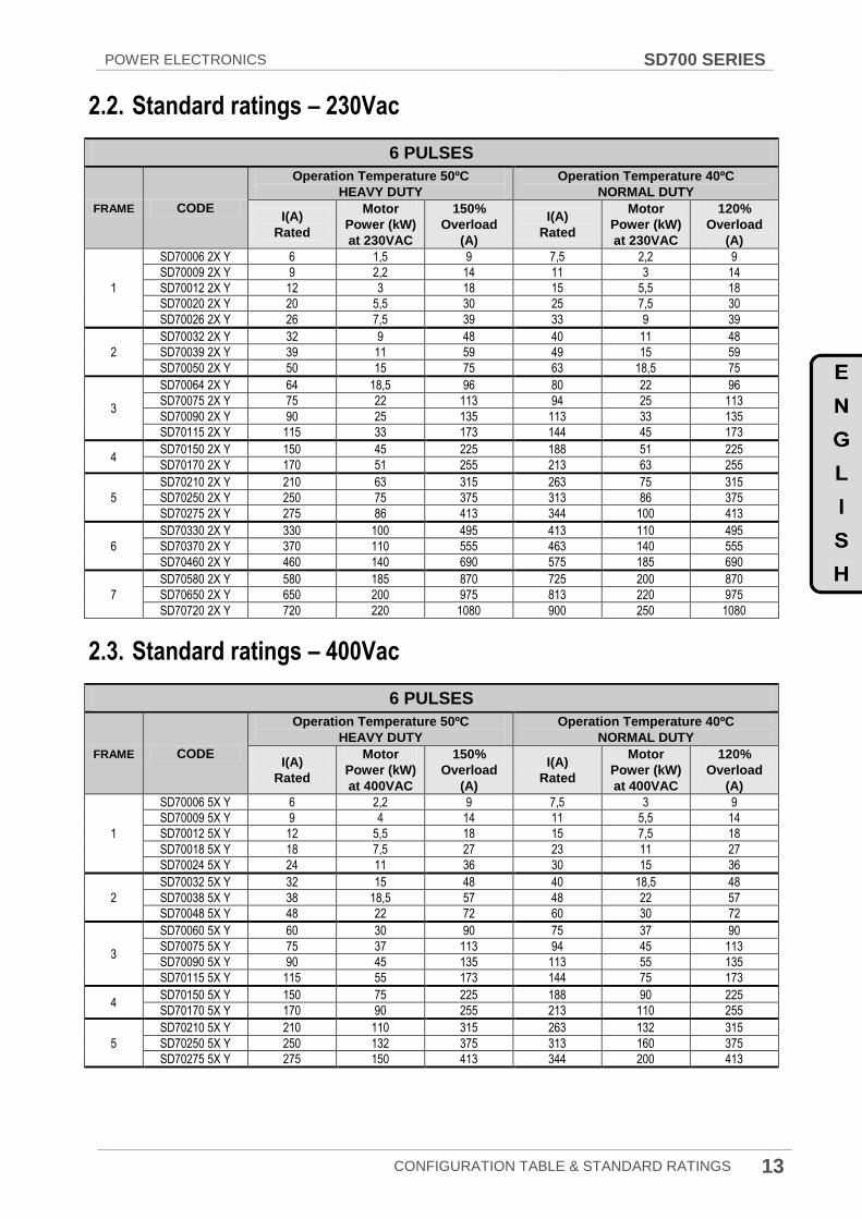
2.2. Standard ratings – 230Vac
6 PULSES
FRAME CODE
Operation Temperature 50ºC
HEAVY DUTY
Operation Temperature 40ºC
NORMAL DUTY
I(A)
Rated
Motor
Power (kW)
at 230VAC
150%
Overload
(A)
I(A)
Rated
Motor
Power (kW)
at 230VAC
120%
Overload
(A)
1
SD70006 2X Y 6 1,5 9 7,5 2,2 9
SD70009 2X Y 9 2,2 14 11 3 14
SD70012 2X Y 12 3 18 15 5,5 18
SD70020 2X Y 20 5,5 30 25 7,5 30
SD70026 2X Y 26 7,5 39 33 9 39
2
SD70032 2X Y 32 9 48 40 11 48
SD70039 2X Y 39 11 59 49 15 59
SD70050 2X Y 50 15 75 63 18,5 75
3
SD70064 2X Y 64 18,5 96 80 22 96
SD70075 2X Y 75 22 113 94 25 113
SD70090 2X Y 90 25 135 113 33 135
SD70115 2X Y 115 33 173 144 45 173
4 SD70150 2X Y 150 45 225 188 51 225
SD70170 2X Y 170 51 255 213 63 255
5
SD70210 2X Y 210 63 315 263 75 315
SD70250 2X Y 250 75 375 313 86 375
SD70275 2X Y 275 86 413 344 100 413
6
SD70330 2X Y 330 100 495 413 110 495
SD70370 2X Y 370 110 555 463 140 555
SD70460 2X Y 460 140 690 575 185 690
7
SD70580 2X Y 580 185 870 725 200 870
SD70650 2X Y 650 200 975 813 220 975
SD70720 2X Y 720 220 1080 900 250 1080
2.3. Standard ratings – 400Vac
6 PULSES
FRAME CODE
Operation Temperature 50ºC
HEAVY DUTY
Operation Temperature 40ºC
NORMAL DUTY
I(A)
Rated
Motor
Power (kW)
at 400VAC
150%
Overload
(A)
I(A)
Rated
Motor
Power (kW)
at 400VAC
120%
Overload
(A)
1
SD70006 5X Y 6 2,2 9 7,5 3 9
SD70009 5X Y 9 4 14 11 5,5 14
SD70012 5X Y 12 5,5 18 15 7,5 18
SD70018 5X Y 18 7,5 27 23 11 27
SD70024 5X Y 24 11 36 30 15 36
2
SD70032 5X Y 32 15 48 40 18,5 48
SD70038 5X Y 38 18,5 57 48 22 57
SD70048 5X Y 48 22 72 60 30 72
3
SD70060 5X Y 60 30 90 75 37 90
SD70075 5X Y 75 37 113 94 45 113
SD70090 5X Y 90 45 135 113 55 135
SD70115 5X Y 115 55 173 144 75 173
4 SD70150 5X Y 150 75 225 188 90 225
SD70170 5X Y 170 90 255 213 110 255
5
SD70210 5X Y 210 110 315 263 132 315
SD70250 5X Y 250 132 375 313 160 375
SD70275 5X Y 275 150 413 344 200 413

SD700 SERIES POWER ELECTRONICS
14 CONFIGURATION TABLE & STANDARD RATINGS
6 PULSES
FRAME CODE
Operation Temperature 50ºC
HEAVY DUTY
Operation Temperature 40ºC
NORMAL DUTY
I(A)
Rated
Motor
Power (kW)
at 400VAC
150%
Overload
(A)
I(A)
Rated
Motor
Power (kW)
at 400VAC
120%
Overload
(A)
6
SD70330 5X Y 330 160 495 413 220 495
SD70370 5X Y 370 200 555 463 250 555
SD70460 5X Y 460 250 690 575 315 690
7
SD70580 5X Y 580 315 870 725 400 870
SD70650 5X Y 650 355 975 813 450 975
SD70720 5X Y 720 400 1080 900 500 1080
8
SD70840 5X Y 840 450 1260 1050 560 1260
SD70925 5X Y 925 500 1388 1156 630 1388
SD70990 5X Y 990 560 1485 1238 710 1485
9
SD71150 5X Y 1150 630 1725 1438 800 1725
SD71260 5X Y 1260 710 1890 1575 900 1890
SD71440 5X Y 1440 800 2160 1800 1000 2160
10 SD71580 5X Y 1580 900 2370 1975 1100 2370
SD71800 5X Y 1800 1000 2700 2250 1200 2700
11 SD72200 5X Y 2200 1200 3300 2750 1500 3300
SD72500 5X Y 2500 1400 3750 3100 1750 3750
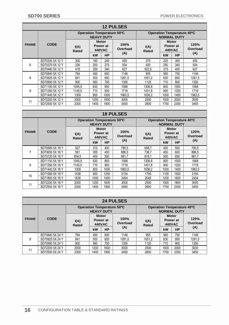
12 PULSES
FRAME CODE
Operation Temperature 50ºC
HEAVY DUTY
Operation Temperature 40ºC
NORMAL DUTY
I(A)
Rated
Motor
Power (kW)
at 400VAC
150%
Overload
(A)
I(A)
Rated
Motor
Power (kW)
at 400VAC
120%
Overload
(A)
6
SD70330 5X 12 Y 330 160 495 413 220 495
SD70370 5X 12 Y 370 200 555 463 250 555
SD70460 5X 12 Y 460 250 690 575 315 690
8
SD70840 5X 12 Y 840 450 1260 1050 560 1260
SD70925 5X 12 Y 925 500 1388 1156 630 1388
SD70990 5X 12 Y 990 560 1485 1238 710 1485
9
SD71150 5X 12 Y 1150 630 1725 1438 800 1725
SD71260 5X 12 Y 1260 710 1890 1575 900 1890
SD71440 5X 12 Y 1440 800 2160 1800 1000 2160
11 SD72200 5X 12 Y 2200 1200 3300 2750 1500 3300
SD72500 5X 12 Y 2500 1400 3750 3100 1750 3750
18 PULSES
FRAME CODE
Operation Temperature 50ºC
HEAVY DUTY
Operation Temperature 40ºC
NORMAL DUTY
I(A)
Rated
Motor
Power (kW)
at 400VAC
150%
Overload
(A)
I(A)
Rated
Motor
Power (kW)
at 400VAC
120%
Overload
(A)
7
SD70580 5X 18 Y 580 315 870 725 400 870
SD70650 5X 18 Y 650 355 975 813 450 975
SD70720 5X 18 Y 720 400 1080 900 500 1080
9
SD71150 5X 18 Y 1150 630 1725 1438 800 1725
SD71260 5X 18 Y 1260 710 1890 1575 900 1890
SD71440 5X 18 Y 1440 800 2160 1800 1000 2160
10 SD71580 5X 18 Y 1580 900 2370 1975 1100 2370
SD71800 5X 18 Y 1800 1000 2700 2250 1200 2700
11 SD72200 5X 18 Y 2200 1200 3300 2750 1500 3300
SD72500 5X 18 Y 2500 1400 3750 3100 1750 3750

POWER ELECTRONICS SD700 SERIES
CONFIGURATION TABLE & STANDARD RATINGS 15
24 PULSES
FRAME CODE
Operation Temperature 50ºC
HEAVY DUTY
Operation Temperature 40ºC
NORMAL DUTY
I(A)
Rated
Motor
Power (kW)
at 400VAC
150%
Overload
(A)
I(A)
Rated
Motor
Power (kW)
at 400VAC
120%
Overload
(A)
8
SD70840 5X 24 Y 840 450 1260 1050 560 1260
SD70925 5X 24 Y 925 500 1388 1156 630 1388
SD70990 5X 24 Y 990 560 1485 1238 710 1485
11 SD72200 5X 24 Y 2200 1200 3300 2750 1500 3300
SD72500 5X 24 Y 2500 1400 3750 3100 1750 3750
2.4. Standard ratings – 440Vac
6 PULSES
FRAME CODE
Operation Temperature 50ºC
HEAVY DUTY
Operation Temperature 40ºC
NORMAL DUTY
I(A)
Rated
Motor
Power at
440VAC
150%
Overload
(A)
I(A)
Rated
Motor
Power at
440VAC
120%
Overload
(A) kW HP kW HP
1
SD70006 5X Y 5,5 2,2 3 8,2 6,8 3 4 8,2
SD70009 5X Y 8 4 5 12 10 5,5 7-1/2 12
SD70012 5X Y 11 5,5 7-1/2 16,5 13,75 7,5 10 16,5
SD70018 5X Y 16 7,5 10 24 20 11 15 24
SD70024 5X Y 22 11 15 33 27,5 15 20 33
2
SD70032 5X Y 29 15 20 43,5 36,25 18,5 25 43,5
SD70038 5X Y 34,5 18,5 25 51,7 43,1 22 30 51,7
SD70048 5X Y 43,6 22 30 65,4 54,5 30 40 65,4
3
SD70060 5X Y 54,5 30 40 81,7 68,1 37 50 81,7
SD70075 5X Y 68 37 50 102 85 45 60 102
SD70090 5X Y 82 45 60 123 102,5 55 75 123
SD70115 5X Y 104,5 55 75 156,7 130,6 75 100 156,7
4 SD70150 5X Y 136 75 100 204 170 90 125 204
SD70170 5X Y 154,5 90 125 231,6 193 110 150 231,6
5
SD70210 5X Y 191 110 150 286,5 238,7 132 180 286,5
SD70250 5X Y 227 132 180 340,5 283,7 160 240 340,5
SD70275 5X Y 250 150 200 375 312,5 200 275 375
6
SD70330 5X Y 300 160 240 450 375 220 300 450
SD70370 5X Y 336 200 275 504 420 250 340 504
SD70460 5X Y 418 250 340 627 522,5 315 400 627
7
SD70580 5X Y 527 315 400 790,5 658,7 400 500 790,5
SD70650 5X Y 591 355 450 886,5 738,7 450 600 886,5
SD70720 5X Y 654,5 400 500 981,7 818,1 500 650 981,7
8
SD70840 5X Y 764 450 600 1146 955 560 750 1146
SD70925 5X Y 841 500 650 1261,5 1051,2 630 850 1261,5
SD70990 5X Y 900 560 750 1350 1125 710 900 1350
9
SD71150 5X Y 1045,5 630 850 1568 1306,8 800 1000 1568
SD71260 5X Y 1145,5 710 900 1718 1431,8 900 1250 1718
SD71440 5X Y 1309 800 1000 1963,5 1636,2 1000 1400 1963,5
10 SD71580 5X Y 1436 900 1250 2154 1795 1100 1500 2154
SD71800 5X Y 1636 1000 1400 2454 2045 1200 1600 2454
11 SD72200 5X Y 2000 1200 1600 3000 2500 1500 2000 3000
SD72500 5X Y 2300 1400 1900 3450 2800 1750 2350 3450
SD700 SERIES POWER ELECTRONICS
16 CONFIGURATION TABLE & STANDARD RATINGS
12 PULSES
FRAME CODE
Operation Temperature 50ºC
HEAVY DUTY
Operation Temperature 40ºC
NORMAL DUTY
I(A)
Rated
Motor
Power at
440VAC
150%
Overload
(A)
I(A)
Rated
Motor
Power at
440VAC
120%
Overload
(A) kW HP kW HP
6
SD70330 5X 12 Y 300 160 240 450 375 220 300 450
SD70370 5X 12 Y 336 200 275 504 420 250 340 504
SD70460 5X 12 Y 418 250 340 627 522,5 315 400 627
8
SD70840 5X 12 Y 764 450 600 1146 955 560 750 1146
SD70925 5X 12 Y 841 500 650 1261,5 1051,2 630 850 1261,5
SD70990 5X 12 Y 900 560 750 1350 1125 710 900 1350
9
SD71150 5X 12 Y 1045,5 630 850 1568 1306,8 800 1000 1568
SD71260 5X 12 Y 1145,5 710 900 1718 1431,8 900 1250 1718
SD71440 5X 12 Y 1309 800 1000 1963,5 1636,2 1000 1400 1963,5
11 SD72200 5X 12 Y 2000 1200 1600 3000 2500 1500 2000 3000
SD72500 5X 12 Y 2300 1400 1900 3450 2800 1750 2350 3450
18 PULSES
FRAME CODE
Operation Temperature 50ºC
HEAVY DUTY
Operation Temperature 40ºC
NORMAL DUTY
I(A)
Rated
Motor
Power at
440VAC
150%
Overload
(A)
I(A)
Rated
Motor
Power at
440VAC
120%
Overload
(A) kW HP kW HP
7
SD70580 5X 18 Y 527 315 400 790,5 658,7 400 500 790,5
SD70650 5X 18 Y 591 355 450 886,5 738,7 450 600 886,5
SD70720 5X 18 Y 654,5 400 500 981,7 818,1 500 650 981,7
9
SD71150 5X 18 Y 1045,5 630 850 1568 1306,8 800 1000 1568
SD71260 5X 18 Y 1145,5 710 900 1718 1431,8 900 1250 1718
SD71440 5X 18 Y 1309 800 1000 1963,5 1636,2 1000 1400 1963,5
10 SD71580 5X 18 Y 1436 900 1250 2154 1795 1100 1500 2154
SD71800 5X 18 Y 1636 1000 1400 2454 2045 1200 1600 2454
11 SD72200 5X 18 Y 2000 1200 1600 3000 2500 1500 1800 3000
SD72500 5X 18 Y 2300 1400 1900 3450 2800 1750 2350 3450
24 PULSES
FRAME CODE
Operation Temperature 50ºC
HEAVY DUTY
Operation Temperature 40ºC
NORMAL DUTY
I(A)
Rated
Motor
Power at
440VAC
150%
Overload
(A)
I(A)
Rated
Motor
Power at
440VAC
120%
Overload
(A) kW HP kW HP
8
SD70840 5X 24 Y 764 450 600 1146 955 560 750 1146
SD70925 5X 24 Y 841 500 650 1261,5 1051,2 630 850 1261,5
SD70990 5X 24 Y 900 560 750 1350 1125 710 900 1350
11 SD72200 5X 24 Y 2000 1200 1600 3000 2500 1500 2000 3000
SD72500 5X 24 Y 2300 1400 1900 3450 2800 1750 2350 3450
POWER ELECTRONICS SD700 SERIES
CONFIGURATION TABLE & STANDARD RATINGS 17
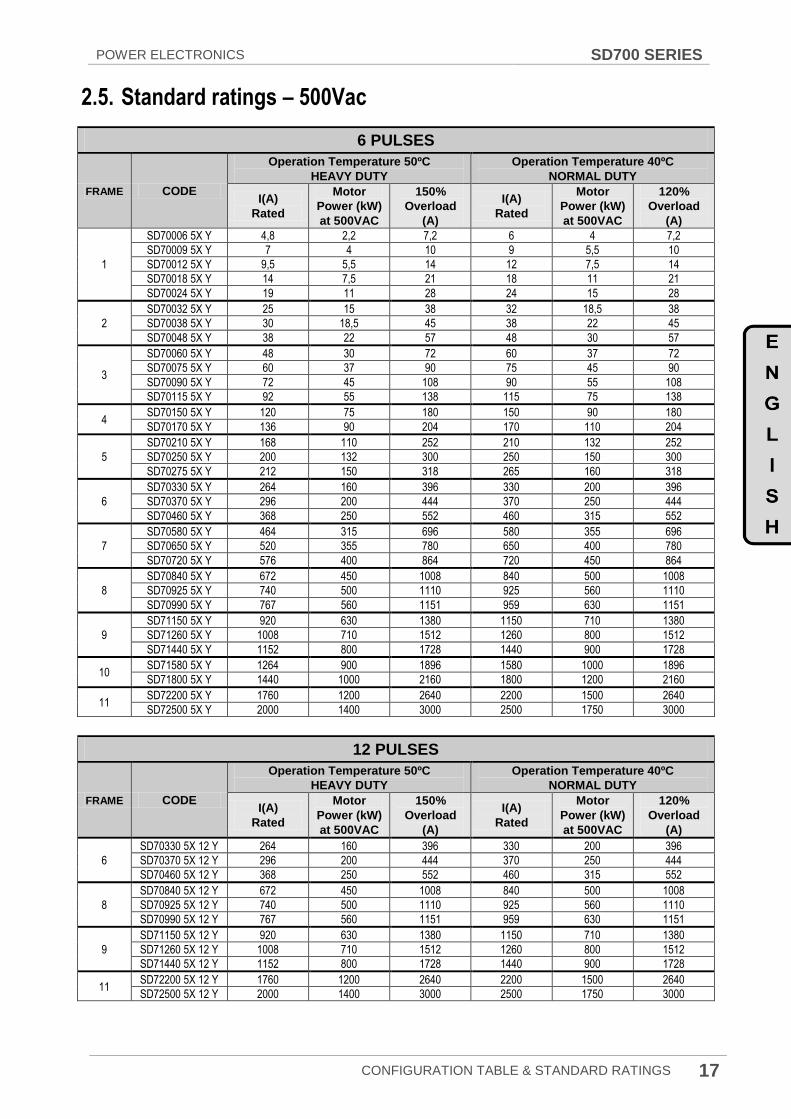
2.5. Standard ratings – 500Vac
6 PULSES
FRAME CODE
Operation Temperature 50ºC
HEAVY DUTY
Operation Temperature 40ºC
NORMAL DUTY
I(A)
Rated
Motor
Power (kW)
at 500VAC
150%
Overload
(A)
I(A)
Rated
Motor
Power (kW)
at 500VAC
120%
Overload
(A)
1
SD70006 5X Y 4,8 2,2 7,2 6 4 7,2
SD70009 5X Y 7 4 10 9 5,5 10
SD70012 5X Y 9,5 5,5 14 12 7,5 14
SD70018 5X Y 14 7,5 21 18 11 21
SD70024 5X Y 19 11 28 24 15 28
2
SD70032 5X Y 25 15 38 32 18,5 38
SD70038 5X Y 30 18,5 45 38 22 45
SD70048 5X Y 38 22 57 48 30 57
3
SD70060 5X Y 48 30 72 60 37 72
SD70075 5X Y 60 37 90 75 45 90
SD70090 5X Y 72 45 108 90 55 108
SD70115 5X Y 92 55 138 115 75 138
4 SD70150 5X Y 120 75 180 150 90 180
SD70170 5X Y 136 90 204 170 110 204
5
SD70210 5X Y 168 110 252 210 132 252
SD70250 5X Y 200 132 300 250 150 300
SD70275 5X Y 212 150 318 265 160 318
6
SD70330 5X Y 264 160 396 330 200 396
SD70370 5X Y 296 200 444 370 250 444
SD70460 5X Y 368 250 552 460 315 552
7
SD70580 5X Y 464 315 696 580 355 696
SD70650 5X Y 520 355 780 650 400 780
SD70720 5X Y 576 400 864 720 450 864
8
SD70840 5X Y 672 450 1008 840 500 1008
SD70925 5X Y 740 500 1110 925 560 1110
SD70990 5X Y 767 560 1151 959 630 1151
9
SD71150 5X Y 920 630 1380 1150 710 1380
SD71260 5X Y 1008 710 1512 1260 800 1512
SD71440 5X Y 1152 800 1728 1440 900 1728
10 SD71580 5X Y 1264 900 1896 1580 1000 1896
SD71800 5X Y 1440 1000 2160 1800 1200 2160
11 SD72200 5X Y 1760 1200 2640 2200 1500 2640
SD72500 5X Y 2000 1400 3000 2500 1750 3000
12 PULSES
FRAME CODE
Operation Temperature 50ºC
HEAVY DUTY
Operation Temperature 40ºC
NORMAL DUTY
I(A)
Rated
Motor
Power (kW)
at 500VAC
150%
Overload
(A)
I(A)
Rated
Motor
Power (kW)
at 500VAC
120%
Overload
(A)
6
SD70330 5X 12 Y 264 160 396 330 200 396
SD70370 5X 12 Y 296 200 444 370 250 444
SD70460 5X 12 Y 368 250 552 460 315 552
8
SD70840 5X 12 Y 672 450 1008 840 500 1008
SD70925 5X 12 Y 740 500 1110 925 560 1110
SD70990 5X 12 Y 767 560 1151 959 630 1151
9
SD71150 5X 12 Y 920 630 1380 1150 710 1380
SD71260 5X 12 Y 1008 710 1512 1260 800 1512
SD71440 5X 12 Y 1152 800 1728 1440 900 1728
11 SD72200 5X 12 Y 1760 1200 2640 2200 1500 2640
SD72500 5X 12 Y 2000 1400 3000 2500 1750 3000

SD700 SERIES POWER ELECTRONICS
18 CONFIGURATION TABLE & STANDARD RATINGS
18 PULSES
FRAME CODE
Operation Temperature 50ºC
HEAVY DUTY
Operation Temperature 40ºC
NORMAL DUTY
I(A)
Rated
Motor
Power (kW)
at 500VAC
150%
Overload
(A)
I(A)
Rated
Motor
Power (kW)
at 500VAC
120%
Overload
(A)
7
SD70580 5X 18 Y 464 315 696 580 355 696
SD70650 5X 18 Y 520 355 780 650 400 780
SD70720 5X 18 Y 576 400 864 720 450 864
9
SD71150 5X 18 Y 920 630 1380 1150 710 1380
SD71260 5X 18 Y 1008 710 1512 1260 800 1512
SD71440 5X 18 Y 1152 800 1728 1440 900 1728
10 SD71580 5X 18 Y 1264 900 1896 1580 1000 1896
SD71800 5X 18 Y 1440 1000 2160 1800 1200 2160
11 SD72200 5X 18 Y 1760 1200 2640 2200 1500 2640
SD72500 5X 18 Y 2000 1400 3000 2500 1750 3000
24 PULSES
FRAME CODE
Operation Temperature 50ºC
HEAVY DUTY
Operation Temperature 40ºC
NORMAL DUTY
I(A)
Rated
Motor
Power (kW)
at 500VAC
150%
Overload
(A)
I(A)
Rated
Motor
Power (kW)
at 500VAC
120%
Overload
(A)
8
SD70840 5X 24 Y 672 450 1008 840 500 1008
SD70925 5X 24 Y 740 500 1110 925 560 1110
SD70990 5X 24 Y 767 560 1151 959 630 1151
11 SD72200 5X 24 Y 1760 1200 2640 2200 1500 2640
SD72500 5X 24 Y 2000 1400 3000 2500 1750 3000
2.6. Standard ratings – 525Vac
6 PULSES
FRAME CODE
Operation Temperature 50ºC
HEAVY DUTY
Operation Range 40ºC
NORMAL DUTY
I(A)
Rated
Motor
Power (kW)
at 525VAC
150%
Overload
(A)
I(A)
Rated
Motor
Power (kW)
at 525VAC
120%
Overload
(A)
4
SD70100 7X Y 100 75 150 122 90 150
SD70120 7X Y 120 90 180 147 110 180
SD70145 7X Y 145 110 218 176 132 218
5 SD70180 7X Y 180 132 270 222 150 270
SD70205 7X Y 205 150 308 254 185 308
6
SD70270 7X Y 270 200 405 334 250 405
SD70295 7X Y 295 220 443 360 280 443
SD70340 7X Y 340 250 510 417 315 510
7
SD70425 7X Y 425 315 638 526 400 638
SD70470 7X Y 470 355 705 586 450 705
SD70535 7X Y 535 400 803 666 500 803
8 SD70660 7X Y 660 500 990 824 600 990
SD70750 7X Y 750 560 1125 936 700 1125
9 SD70845 7X Y 845 630 1268 1052 800 1268
SD70950 7X Y 950 710 1425 1157 900 1425
10
SD71070 7X Y 1070 800 1605 1337 1000 1605
SD71205 7X Y 1205 900 1808 1504 1100 1808
SD71340 7X Y 1340 1000 2010 1672 1250 2010
SD71605 7X Y 1605 1200 2408 2006 1500 2408
11 SD72005 7X Y 2005 1500 3008 2507 1900 3008
POWER ELECTRONICS SD700 SERIES
CONFIGURATION TABLE & STANDARD RATINGS 19
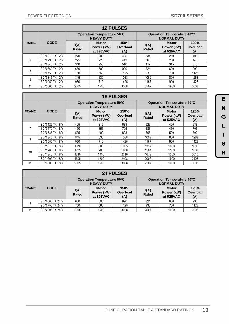
12 PULSES
FRAME CODE
Operation Temperature 50ºC
HEAVY DUTY
Operation Temperature 40ºC
NORMAL DUTY
I(A)
Rated
Motor
Power (kW)
at 525VAC
150%
Overload
(A)
I(A)
Rated
Motor
Power (kW)
at 525VAC
120%
Overload
(A)
6
SD70270 7X 12 Y 270 200 405 334 250 405
SD70295 7X 12 Y 295 220 443 360 280 443
SD70340 7X 12 Y 340 250 510 417 315 510
8 SD70660 7X 12 Y 660 500 990 824 600 990
SD70750 7X 12 Y 750 560 1125 936 700 1125
9 SD70845 7X 12 Y 845 630 1268 1052 800 1268
SD70950 7X 12 Y 950 710 1425 1157 900 1425
11 SD72005 7X 12 Y 2005 1500 3008 2507 1900 3008
18 PULSES
FRAME CODE
Operation Temperature 50ºC
HEAVY DUTY
Operation Temperature 40ºC
NORMAL DUTY
I(A)
Rated
Motor
Power (kW)
at 525VAC
150%
Overload
(A)
I(A)
Rated
Motor
Power (kW)
at 525VAC
120%
Overload
(A)
7
SD70425 7X 18 Y 425 315 638 526 400 638
SD70470 7X 18 Y 470 355 705 586 450 705
SD70535 7X 18 Y 535 400 803 666 500 803
9 SD70845 7X 18 Y 845 630 1268 1052 800 1268
SD70950 7X 18 Y 950 710 1425 1157 900 1425
10
SD71070 7X 18 Y 1070 800 1605 1337 1000 1605
SD71205 7X 18 Y 1205 900 1808 1504 1100 1808
SD71340 7X 18 Y 1340 1000 2010 1672 1250 2010
SD71605 7X 18 Y 1605 1200 2408 2006 1500 2408
11 SD72005 7X 18 Y 2005 1500 3008 2507 1900 3008
24 PULSES
FRAME CODE
Operation Temperature 50ºC
HEAVY DUTY
Operation Temperature 40ºC
NORMAL DUTY
I(A)
Rated
Motor
Power (kW)
at 525VAC
150%
Overload
(A)
I(A)
Rated
Motor
Power (kW)
at 525VAC
120%
Overload
(A)
8 SD70660 7X 24 Y 660 500 990 824 600 990
SD70750 7X 24 Y 750 560 1125 936 700 1125
11 SD72005 7X 24 Y 2005 1500 3008 2507 1900 3008

SD700 SERIES POWER ELECTRONICS
20 CONFIGURATION TABLE & STANDARD RATINGS
2.7. Standard ratings – 690Vac
6 PULSES
FRAME CODE
Operation Temperature 50ºC
HEAVY DUTY
Operation Temperature 40ºC
NORMAL DUTY
I(A)
Rated
Motor
Power (kW)
at 690VAC
150%
Overload
(A)
I(A)
Rated
Motor
Power (kW)
at 690VAC
120%
Overload
(A)
3 SD70052 6X Y 52 45 78 65 55 78
SD70062 6X Y 62 55 93 78 75 93
4 SD70080 6X Y 80 75 120 100 90 120
SD70105 6X Y 105 90 157 131 110 157
5
SD70130 6X Y 130 110 195 163 132 195
SD70150 6X Y 150 132 225 188 160 225
SD70170 6X Y 170 160 255 213 200 255
6
SD70210 6X Y 210 200 315 263 250 315
SD70260 6X Y 260 250 390 325 315 390
SD70320 6X Y 320 315 480 400 355 480
7 SD70385 6X Y 385 355 578 481 450 578
SD70460 6X Y 460 450 690 575 500 690
8 SD70550 6X Y 550 500 825 688 630 825
SD70660 6X Y 660 630 990 825 800 990
9
SD70750 6X Y 750 710 1125 938 900 1125
SD70840 6X Y 840 800 1260 1050 1000 1260
SD70950 6X Y 950 900 1425 1188 1100 1425
10
SD71140 6X Y 1140 1000 1710 1425 1300 1710
SD71270 6X Y 1270 1200 1905 1588 1600 1905
SD71420 6X Y 1420 1400 2130 1775 1700 2130
11 SD71500 6X Y 1500 1500 2250 1875 1800 2250
SD71800 6X Y 1800 1800 2700 2250 2000 2700
12 PULSES
FRAME CODE
Operation Temperature 50ºC
HEAVY DUTY
Operation Temperature 40ºC
NORMAL DUTY
I(A)
Rated
Motor
Power (kW)
at 690VAC
150%
Overload
(A)
I(A)
Rated
Motor
Power (kW)
at 690VAC
120%
Overload
(A)
6
SD70210 6X 12 Y 210 200 315 263 250 315
SD70260 6X 12 Y 260 250 390 325 315 390
SD70320 6X 12 Y 320 315 480 400 355 480
8 SD70550 6X 12 Y 550 500 825 688 630 825
SD70660 6X 12 Y 660 630 990 825 800 990
9
SD70750 6X 12 Y 750 710 1125 938 900 1125
SD70840 6X 12 Y 840 800 1260 1050 1000 1260
SD70950 6X 12 Y 950 900 1425 1188 1100 1425
11 SD71500 6X 12 Y 1500 1500 2250 1875 1800 2250
SD71800 6X 12 Y 1800 1800 2700 2250 2000 2700

POWER ELECTRONICS SD700 SERIES
CONFIGURATION TABLE & STANDARD RATINGS 21
18 PULSES
FRAME CODE
Operation Temperature 50ºC
HEAVY DUTY
Operation Temperature 40ºC
NORMAL DUTY
I(A)
Rated
Motor
Power (kW)
at 690VAC
150%
Overload
(A)
I(A)
Rated
Motor
Power (kW)
at 690VAC
120%
Overload
(A)
7 SD70385 6X 18 Y 385 355 578 481 450 578
SD70460 6X 18 Y 460 450 690 575 500 690
9
SD70750 6X 18 Y 750 710 1125 938 900 1125
SD70840 6X 18 Y 840 800 1260 1050 1000 1260
SD70950 6X 18 Y 950 900 1425 1188 1100 1425
10
SD71140 6X 18 Y 1140 1000 1710 1425 1300 1710
SD71270 6X 18 Y 1270 1200 1905 1588 1600 1905
SD71420 6X 18 Y 1420 1400 2130 1775 1700 2130
11 SD71500 6X 18 Y 1500 1500 2250 1875 1800 2250
SD71800 6X 18 Y 1800 1800 2700 2250 2000 2700
24 PULSES
FRAME CODE
Operation Temperature 50ºC
HEAVY DUTY
Operation Temperature 40ºC
NORMAL DUTY
I(A)
Rated
Motor
Power (kW)
at 690VAC
150%
Overload
(A)
I(A)
Rated
Motor
Power (kW)
at 690VAC
120%
Overload
(A)
8 SD70550 6X 24 Y 550 500 825 680 630 825
SD70660 6X 24 Y 660 630 990 825 800 990
11 SD71500 6X 24 Y 1500 1500 2250 1875 1800 2250
SD71800 6X 24 Y 1800 1800 2700 2250 2000 2700
SD700 SERIES POWER ELECTRONICS
22 TECHNICAL CHARACTERISTICS
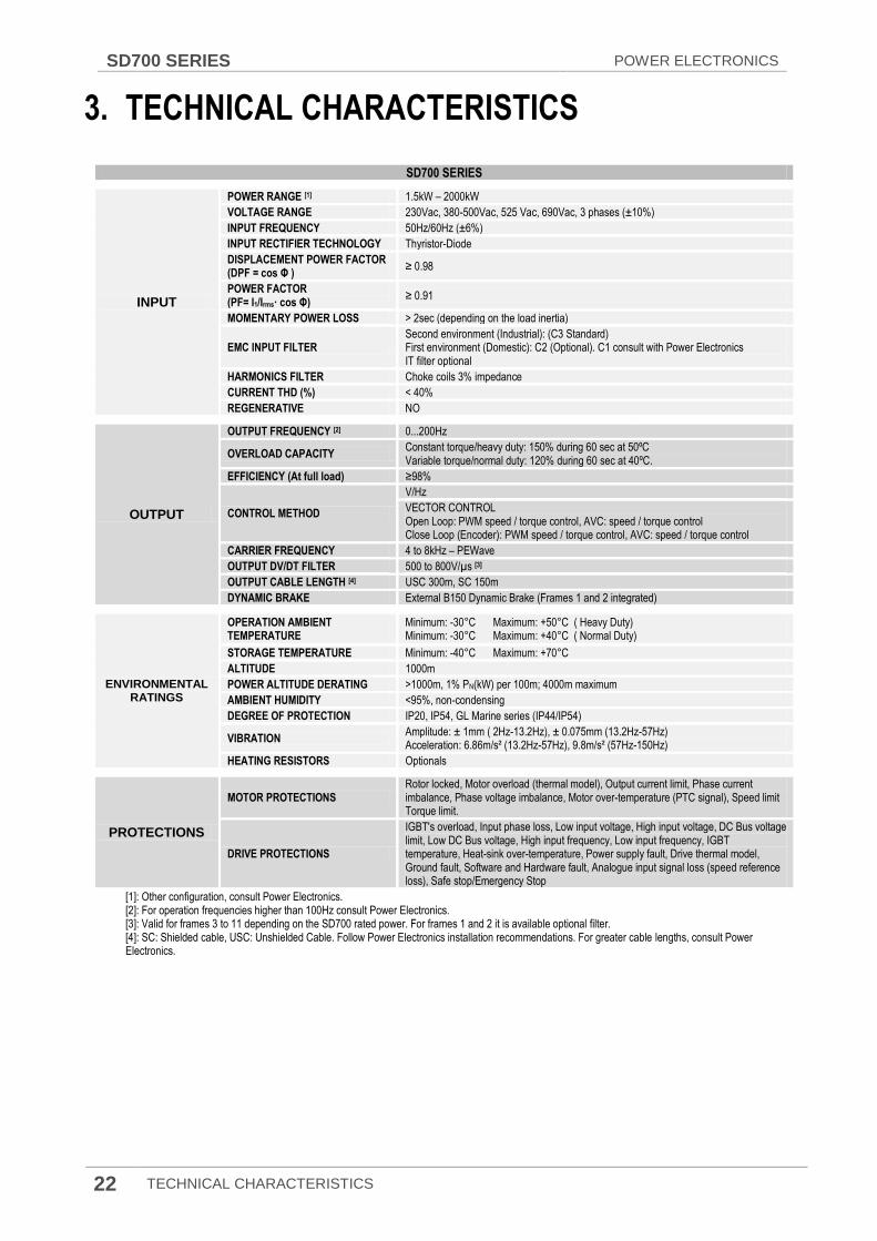
3. TECHNICAL CHARACTERISTICS
SD700 SERIES
INPUT
POWER RANGE [1] 1.5kW – 2000kW
VOLTAGE RANGE 230Vac, 380-500Vac, 525 Vac, 690Vac, 3 phases (±10%)
INPUT FREQUENCY 50Hz/60Hz (±6%)
INPUT RECTIFIER TECHNOLOGY Thyristor-Diode
DISPLACEMENT POWER FACTOR (DPF = cos Φ )
≥ 0.98
POWER FACTOR (PF= I1/Irms· cos Φ)
≥ 0.91
MOMENTARY POWER LOSS > 2sec (depending on the load inertia)
EMC INPUT FILTER Second environment (Industrial): (C3 Standard) First environment (Domestic): C2 (Optional). C1 consult with Power Electronics IT filter optional
HARMONICS FILTER Choke coils 3% impedance
CURRENT THD (%) < 40%
REGENERATIVE NO
OUTPUT
OUTPUT FREQUENCY [2] 0...200Hz
OVERLOAD CAPACITY Constant torque/heavy duty: 150% during 60 sec at 50ºC Variable torque/normal duty: 120% during 60 sec at 40ºC.
EFFICIENCY (At full load) ≥98%
CONTROL METHOD
V/Hz
VECTOR CONTROL Open Loop: PWM speed / torque control, AVC: speed / torque control Close Loop (Encoder): PWM speed / torque control, AVC: speed / torque control
CARRIER FREQUENCY 4 to 8kHz – PEWave
OUTPUT DV/DT FILTER 500 to 800V/µs [3]
OUTPUT CABLE LENGTH [4] USC 300m, SC 150m
DYNAMIC BRAKE External B150 Dynamic Brake (Frames 1 and 2 integrated)
ENVIRONMENTAL RATINGS
OPERATION AMBIENT TEMPERATURE
Minimum: -30°C Maximum: +50°C ( Heavy Duty) Minimum: -30°C Maximum: +40°C ( Normal Duty)
STORAGE TEMPERATURE Minimum: -40°C Maximum: +70°C
ALTITUDE 1000m
POWER ALTITUDE DERATING >1000m, 1% PN(kW) per 100m; 4000m maximum
AMBIENT HUMIDITY <95%, non-condensing
DEGREE OF PROTECTION IP20, IP54, GL Marine series (IP44/IP54)
VIBRATION Amplitude: ± 1mm ( 2Hz-13.2Hz), ± 0.075mm (13.2Hz-57Hz) Acceleration: 6.86m/s² (13.2Hz-57Hz), 9.8m/s² (57Hz-150Hz)
HEATING RESISTORS Optionals
PROTECTIONS
MOTOR PROTECTIONS Rotor locked, Motor overload (thermal model), Output current limit, Phase current imbalance, Phase voltage imbalance, Motor over-temperature (PTC signal), Speed limit Torque limit.
DRIVE PROTECTIONS
IGBT's overload, Input phase loss, Low input voltage, High input voltage, DC Bus voltage limit, Low DC Bus voltage, High input frequency, Low input frequency, IGBT temperature, Heat-sink over-temperature, Power supply fault, Drive thermal model, Ground fault, Software and Hardware fault, Analogue input signal loss (speed reference loss), Safe stop/Emergency Stop
[1]: Other configuration, consult Power Electronics. [2]: For operation frequencies higher than 100Hz consult Power Electronics. [3]: Valid for frames 3 to 11 depending on the SD700 rated power. For frames 1 and 2 it is available optional filter. [4]: SC: Shielded cable, USC: Unshielded Cable. Follow Power Electronics installation recommendations. For greater cable lengths, consult Power Electronics.
POWER ELECTRONICS SD700 SERIES
TECHNICAL CHARACTERISTICS 23
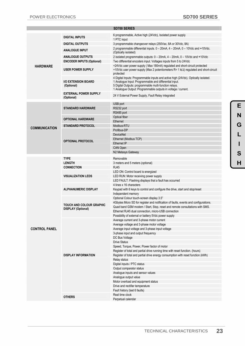
SD700 SERIES
HARDWARE
DIGITAL INPUTS 6 programmable, Active high (24Vdc), Isolated power supply
1 PTC input
DIGITAL OUTPUTS 3 programmable changeover relays (250Vac, 8A or 30Vdc, 8A)
ANALOGUE INPUT 2 programmable differential inputs. 0 – 20mA, 4 – 20mA, 0 – 10Vdc and 10Vdc. (Optically isolated)
ANALOGUE OUTPUTS 2 isolated programmable outputs: 0 – 20mA, 4 – 20mA, 0 – 10Vdc and 10Vdc
ENCODER INPUTS (Optional) Two differential encoders input. Voltages inputs from 5 to 24Vdc
USER POWER SUPPLY
+24Vdc user power supply ( Max 180mA) regulated and short-circuit protected
+10Vdc user power supply (Max 2 potentiometers R= 1 k ) regulated and short-circuit protected
I/O EXTENSION BOARD (Optional)
4 Digital Inputs: Programmable inputs and active high (24Vdc). Optically isolated. 1 Analogue Input: Programmable and differential input. 5 Digital Outputs: programmable multi-function relays. 1 Analogue Output: Programmable outputs in voltage / current.
EXTERNAL POWER SUPPLY (Optional)
24 V External Power Supply, Fault Relay integrated
COMMUNICATION
STANDARD HARDWARE
USB port
RS232 port
RS485 port
OPTIONAL HARDWARE Optical fiber
Ethernet
STANDARD PROTOCOL Modbus-RTU
OPTIONAL PROTOCOL
Profibus-DP
DeviceNet
Ethernet (Modbus TCP)
Ethernet IP
CAN Open
N2 Metasys Gateway
CONTROL PANEL
TYPE Removable
LENGTH 3 meters and 5 meters (optional)
CONNECTION RJ45
VISUALIZATION LEDS
LED ON: Control board is energized
LED RUN: Motor receiving power supply
LED FAULT: Flashing displays that a fault has occurred
ALPHANUMERIC DISPLAY
4 lines x 16 characters
Keypad with 6 keys to control and configure the drive, start and stop/reset
Independent memory
TOUCH AND COLOUR GRAPHIC DISPLAY (Optional)
Optional Colour touch-screen display 3.5”
4Gbytes Micro SD for register and notification of faults, events and configurations.
Quad band GSM modem / Start, Stop, reset and remote consultations with SMS.
Ethernet RJ45 dual connection, micro-USB connection
Possibility of external or battery 5Vdc power supply
DISPLAY INFORMATION
Average current and 3-phase motor current
Average voltage and 3-phase motor voltage
Average input voltage and 3-phase input voltage
3-phase input and output frequency
DC Bus Voltage
Drive Status
Speed, Torque, Power, Power factor of motor
Register of total and partial drive running time with reset function. (hours)
Register of total and partial drive energy consumption with reset function (kWh)
Relay status
Digital inputs / PTC status
Output comparator status
Analogue inputs and sensor values
Analogue output value
Motor overload and equipment status
Drive and rectifier temperature
Fault history (last 6 faults)
OTHERS Real time clock
Perpetual calendar
SD700 SERIES POWER ELECTRONICS
24 TECHNICAL CHARACTERISTICS
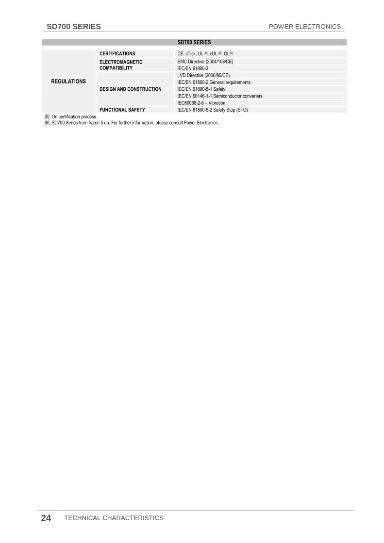
SD700 SERIES
REGULATIONS
CERTIFICATIONS CE, cTick, UL [5], cUL [5], GL[6]
ELECTROMAGNETIC COMPATIBILITY
EMC Directive (2004/108/CE)
IEC/EN 61800-3
DESIGN AND CONSTRUCTION
LVD Directive (2006/95/CE)
IEC/EN 61800-2 General requirements
IEC/EN 61800-5-1 Safety
IEC/EN 60146-1-1 Semiconductor converters
IEC60068-2-6 – Vibration
FUNCTIONAL SAFETY IEC/EN 61800-5-2 Safety Stop (STO)
[5]: On certification process. [6]: SD700 Series from frame 5 on. For further information, please consult Power Electronics.

POWER ELECTRONICS SD700 SERIES
RECEPTION, HANDLING AND TRANSPORTATION 25
4. RECEPTION, HANDLING AND TRANSPORTATION
CAUTION Read carefully the following installation instructions for a correct mechanical installation. Otherwise, the equipment can be damaged and lead to injury to people.
4.1. Reception and Storage
The SD700 are carefully tested and perfectly packed before delivering. In the event of transport damage, please ensure that you notify the transport agency and Power Electronics: 902 40 20 70 (International +34 96 136 65 57) or your nearest agent, within 24hrs from receipt of the goods.
Make sure model and serial number of the drive are the same on the delivery note and unit.
Drive‟s storage should be sun and moisture protected and with an ambient temperature between -40°C and +70°C, < 95 RH without condensation. It is recommended not pile more than two units.
4.2. Handling and Transportation
Only the transport methods described in this document or in the delivery notes are permissible. Any other transport method or system could damage the unit.
SD700 is delivered horizontally. Frames 1 and 2 are delivered in a cardboard box and frames 3 on are delivered fastened to a wooden pallet, covered with a cardboard box in frames 3 and 4 or with a wooden box in frames 5 on. Depending on the transport method, the drive could be moisture protected with a vacuum plastic bag. Move the complete pallet as close as possible to its final installation place before unpacking, to avoid any damage during transportation.
It is mandatory to transport it with a pallet truck, forklift or crane fork, taking care about the load distribution and centre of gravity. Check the size and weight of VFD components to choose proper lifting equipment with a capacity greater than the drive weight.
Unpack the drive carefully. Do not use edge tool to protect the product from damage. After open the package, please check the goods contained. Verify the item numbers contained within the package with the packing inventory list. Please set aside and reserve, if contained, the case of spare parts shipped with the product. There should be no evident damage caused by vibration, dropping or moisture.
CAUTION
If the maximum tonnage of cranes cannot meet the requirement, it could cause damage to the
equipment and lead to injury to people.

SD700 SERIES POWER ELECTRONICS
26 RECEPTION, HANDLING AND TRANSPORTATION
Figure 4.1 Frame 5 unpacking
To unpack, if necessary, unscrew the bolts that fix the wooden box with the pallet. Then, the drive is fixed to the pallet through the L shapes place in its four corners, unscrew all the fixation screws, otherwise if the cabinet is lifted the pallet could cause damage.
To rise to an upright position use only a crane or forklift equipped with belts or slings. Lift it carefully pulling from the top eyebolts.
CAUTION Do not lift the VSD from the eyebolts place on the top part under any circumstance, it could cause
damage to the equipment and lead to injury to people.
Once it is upright positioned, reallocate the belts/slings, the forklift or crane‟s fork to lift the drive pulling from the bottom part. Avoid brusque movements and shocks during transportation. At the time of placing the drive on the floor, stop lowering it just before reaching the floor and then slowly lower it on the floor to avoid any shock.
Figure 4.2 Lifting of the equipment
During handling and transportation, the goods should not be exposed to moisture, overturned, inverted, tilted or impacted. The tilting angle should be no more than 30º.
POWER ELECTRONICS SD700 SERIES
MECHANICAL INSTALLATION 27
5. MECHANICAL INSTALLATION
CAUTION The installation must be done by qualified personal.
Otherwise, the equipment can be damaged and lead to injury to people.
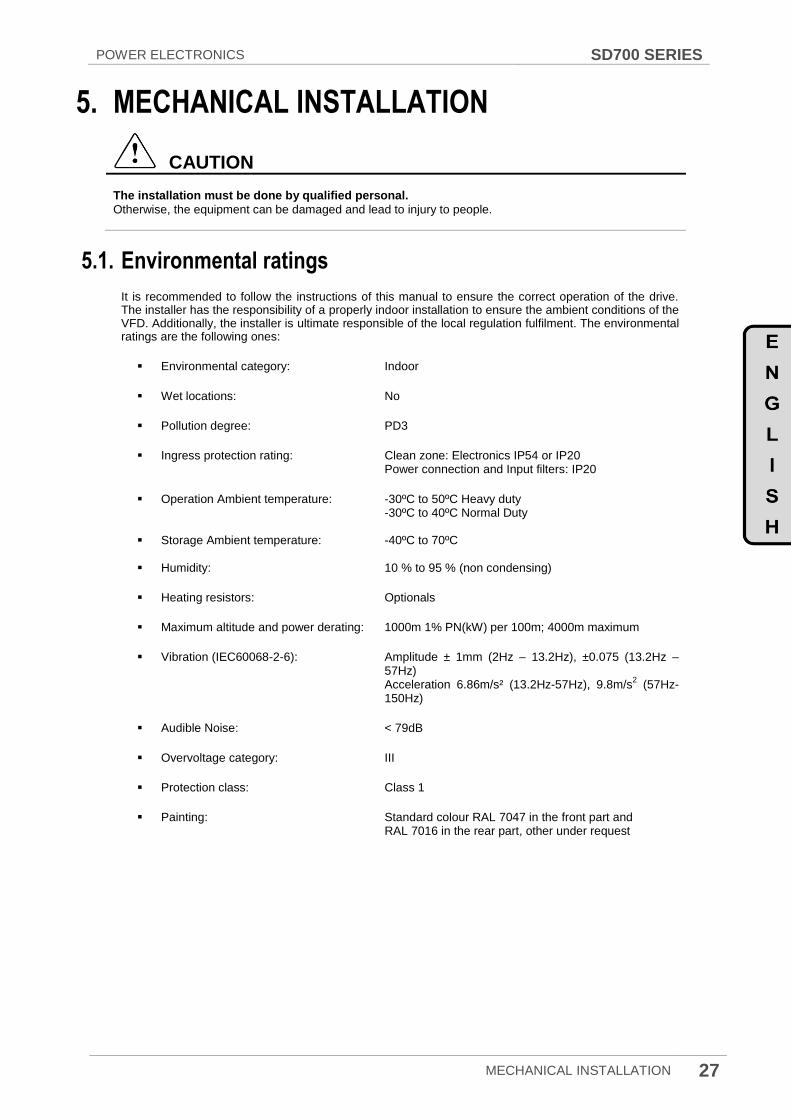
5.1. Environmental ratings
It is recommended to follow the instructions of this manual to ensure the correct operation of the drive. The installer has the responsibility of a properly indoor installation to ensure the ambient conditions of the VFD. Additionally, the installer is ultimate responsible of the local regulation fulfilment. The environmental ratings are the following ones:
Environmental category: Indoor
Wet locations: No
Pollution degree: PD3
Ingress protection rating: Clean zone: Electronics IP54 or IP20 Power connection and Input filters: IP20
Operation Ambient temperature: -30ºC to 50ºC Heavy duty -30ºC to 40ºC Normal Duty Storage Ambient temperature: -40ºC to 70ºC
Humidity: 10 % to 95 % (non condensing)
Heating resistors: Optionals
Maximum altitude and power derating: 1000m 1% PN(kW) per 100m; 4000m maximum
Vibration (IEC60068-2-6): Amplitude ± 1mm (2Hz – 13.2Hz), ±0.075 (13.2Hz – 57Hz)
Acceleration 6.86m/s² (13.2Hz-57Hz), 9.8m/s2 (57Hz-
150Hz)
Audible Noise: < 79dB
Overvoltage category: III
Protection class: Class 1
Painting: Standard colour RAL 7047 in the front part and RAL 7016 in the rear part, other under request
SD700 SERIES POWER ELECTRONICS
28 MECHANICAL INSTALLATION
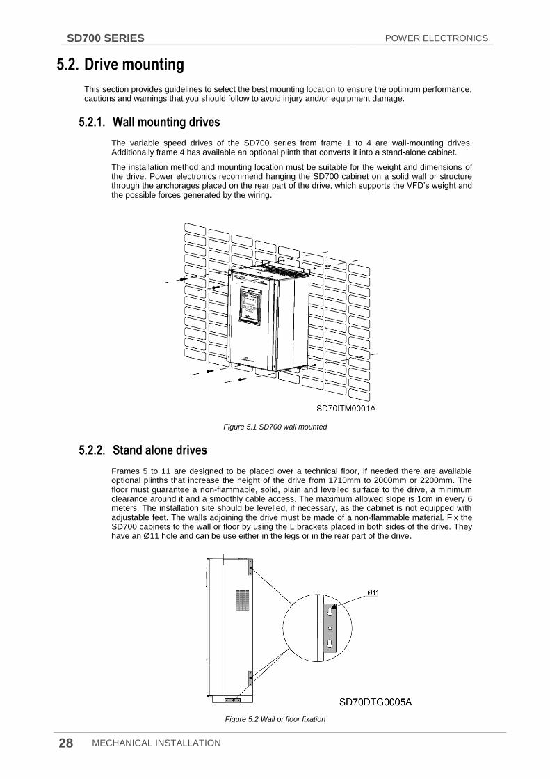
5.2. Drive mounting
This section provides guidelines to select the best mounting location to ensure the optimum performance, cautions and warnings that you should follow to avoid injury and/or equipment damage.
5.2.1. Wall mounting drives
The variable speed drives of the SD700 series from frame 1 to 4 are wall-mounting drives. Additionally frame 4 has available an optional plinth that converts it into a stand-alone cabinet.
The installation method and mounting location must be suitable for the weight and dimensions of the drive. Power electronics recommend hanging the SD700 cabinet on a solid wall or structure through the anchorages placed on the rear part of the drive, which supports the VFD‟s weight and the possible forces generated by the wiring.
Figure 5.1 SD700 wall mounted
5.2.2. Stand alone drives
Frames 5 to 11 are designed to be placed over a technical floor, if needed there are available optional plinths that increase the height of the drive from 1710mm to 2000mm or 2200mm. The floor must guarantee a non-flammable, solid, plain and levelled surface to the drive, a minimum clearance around it and a smoothly cable access. The maximum allowed slope is 1cm in every 6 meters. The installation site should be levelled, if necessary, as the cabinet is not equipped with adjustable feet. The walls adjoining the drive must be made of a non-flammable material. Fix the SD700 cabinets to the wall or floor by using the L brackets placed in both sides of the drive. They have an Ø11 hole and can be use either in the legs or in the rear part of the drive.
Figure 5.2 Wall or floor fixation

POWER ELECTRONICS SD700 SERIES
MECHANICAL INSTALLATION 29
It is recommended to construct a cable duct below the middle part of the cabinet. The duct width may not exceed 300 mm and the contact surface of the floor must resist the cabinet weight that lies on the legs.
5.3. Clearances
The SD700 VFD must be installed in vertical position, and firmly fastened through the dedicated anchorages placed in the rear part of the drive that avoid any movement.
If the equipment is installed inside a cabinet, ensure that the hot air expelled from the VFD is evacuated outside. This hot air can be aspirated again so the drive may suffer from overheating. To ensure a suitable cooling avoid the recirculation of air and keep the minimum clearance distances indicated below.
Figure 5.3 Minimum clearances for frames 1 to 4
Figure 5.4 Minimum clearances for frames 5 to 11
FRAME DISTANCE (mm) FRONT
CLEARANCE A B
1 200 200 700
2 200 200 800
3 200 200 800
4 300 300 820
FRAME
DISTANCE
(mm) FRONT
CLEARANCE A
5 400 930
6 400 940
7 400 1260
8 400 1260
9 400 940
10 400 1260
11 400 1260
SD700 SERIES POWER ELECTRONICS
30 MECHANICAL INSTALLATION
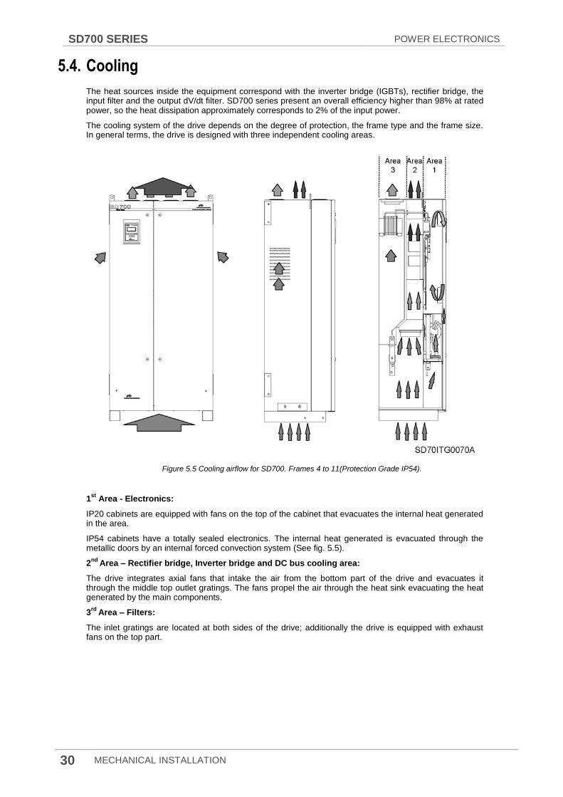
5.4. Cooling
The heat sources inside the equipment correspond with the inverter bridge (IGBTs), rectifier bridge, the input filter and the output dV/dt filter. SD700 series present an overall efficiency higher than 98% at rated power, so the heat dissipation approximately corresponds to 2% of the input power.
The cooling system of the drive depends on the degree of protection, the frame type and the frame size. In general terms, the drive is designed with three independent cooling areas.
Figure 5.5 Cooling airflow for SD700. Frames 4 to 11(Protection Grade IP54).
1st
Area - Electronics:
IP20 cabinets are equipped with fans on the top of the cabinet that evacuates the internal heat generated in the area.
IP54 cabinets have a totally sealed electronics. The internal heat generated is evacuated through the metallic doors by an internal forced convection system (See fig. 5.5).
2nd
Area – Rectifier bridge, Inverter bridge and DC bus cooling area:
The drive integrates axial fans that intake the air from the bottom part of the drive and evacuates it through the middle top outlet gratings. The fans propel the air through the heat sink evacuating the heat generated by the main components.
3rd
Area – Filters:
The inlet gratings are located at both sides of the drive; additionally the drive is equipped with exhaust fans on the top part.

POWER ELECTRONICS SD700 SERIES
MECHANICAL INSTALLATION 31
The following figure identifies the gratings and fans of the different cooling areas.
Figure 5.6 SD700 gratings and fans
FRAMES
ID 1 2 3 4 5 6 7 8 9 10 11
AREA 2
OPERATION FLOW (m3/h) (*) D 64-77 239-287 306-367 342-410 396-475 486-583 720-864 972-1166 1458-1750 2178-2614 2898-3478
INLET GRATING NET SECTION (m2) A 0.081 0.016 0.025 0.031 0.034 0.064 0.101 0.123 0.192 0.303 0.369
OUTLET GRATING NET SECTION (m2) D 0.003 0.013 0.017 0.019 0.022 0.027 0.040 0.054 0.081 0.121 0.161
AREA 3 OPERATION FLOW (m3/h) C - - - 180 360 720 1080 1440 2160 3240 4320
INLET GRATING NET SECTION (m2) B 0.081 0.016 0.025 0.031 0.034 0.041 0.041 0.041 0.122 0.122 0.122
Heat dissipation
The heat generated by the SD700 depends on the carrier frequency (Hz), the grid frequency and the load. It could be estimated by the following equation. Rated power condition is the worst case.
P loss [W] = 0,02 · Pmotor [W]
(*)The air velocity, which passes through the gratings, varies between 5 and 6 m/s depending on the blocking of the
gratings.

SD700 SERIES POWER ELECTRONICS
32 POWER CONNECTION
6. POWER CONNECTION
CAUTION Read carefully the following installation instructions for a correct electrical installation.
Otherwise, it could cause damage to the equipment and lead to injury to people.
6.1. Basic configuration
Proper safety equipment must be selected and correct connections must be done to ensure proper operation. An incorrectly applied or installed drive can result in system malfunction or reduction in product lifetime as well as component damage. You must read and understand this manual thoroughly before proceeding.
Figure 6.1 Basic configuration
AC Power Supply
Use a power supply with a voltage range compatible with the selected drive. SD700 drives are available for TN and TT grids, or IT grids (floating earth). Check the serial number to ensure the correct drive selection.
External line-side protection
Select fuses and switches in accordance with the recommendation within this manual and the applicable national and local codes. Do not use it for the purpose of starting or stopping the drive. IT grids should be externally protected against insulation breakdowns and overvoltages.
SD700 Installation
Install the drive following the recommendation within this manual in relation with the cooling requirements, position, clearances, wiring access and ground connection.
Motor cables
Select and install the motor cables according to the recommendation within this manual and the applicable national and local codes. An incorrect motor cable selection and installation could cause EMC filtering malfunction and motor damaged.
Motor Do not connect power factor capacitors, surge arrestors or RFI filters to the output side of the drive.

POWER ELECTRONICS SD700 SERIES
POWER CONNECTION 33
6.2. Topology
SD700 drive operates according to the principle of pulse-width modulation (PWM). Varying the power supply voltage and the grid frequency, it is possible to control the speed and torque of the connected induction three-phase motors by means of its main components: rectifier bridge, the DC bus, inverter bridge, and power and control board.
Figure 6.2 General Block Scheme for frames 3 to 11
SD700 integrate as standard input chokes filters. These filters significantly reduce the THDi values, and increase the impedance line protecting the drive against electrical distortions. Depending on the frame, the input choke filter is installed in the input side or in the DC bus. For frames 3 to 11 filter is installed in the input side. For frames 1 and 2 filter is installed in the DC bus (see figure 6.3).
SD700 frames 5 to 11 integrate as standard ultra fast fuses that protect the drive against downstream overcurrents. Additionally the drive integrates multiple electrical protections that protect the drive and the motor as a motor relay does.
The SD700 includes a power and a control board to control the rectifier thyristor diode‟s bridge shooting, the inverter IGBT‟s bridge shooting, the soft charge, the DC bus voltage and the motor performance. In addition, control board integrates the interface terminals such as communication ports, the digital and analogue inputs and outputs, colour touch-screen display and alphanumeric display, etc.
The inverter bridge generates the PWM wave that controls the motor performance (voltage, current, torque, etc...). SD700 Series by Power Electronics, integrate as standard output dV/dt filters and a CLAMP system that reduces significantly the dV/dt rise time below 500V/μs - 800V/μs, therefore, it reduces the voltages peaks at the motor windings, the common mode currents and the EMC emissions.
SD700 SERIES POWER ELECTRONICS
34 POWER CONNECTION
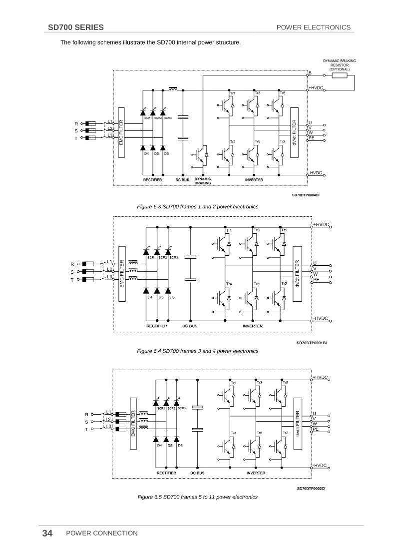
The following schemes illustrate the SD700 internal power structure.
Figure 6.3 SD700 frames 1 and 2 power electronics
Figure 6.4 SD700 frames 3 and 4 power electronics
Figure 6.5 SD700 frames 5 to 11 power electronics

POWER ELECTRONICS SD700 SERIES
POWER CONNECTION 35
6.3. Power connection and wiring
CAUTION The following installation recommendations are suitable for TN and TT grids. For IT grids check the dedicated section. Otherwise, it could cause damage to the equipment and lead to injury to people.
Wiring and periodic inspections should be performed at least 10 minutes after disconnecting the input power. To remove the front cover check that the DC Link red LED is off, then remove the metallic cover and check with a multimeter the following measures:
• Measure between the output power busbars U, V, W and the cabinet and check that the voltage is around 0V.
• Measure that the DC link terminals +, - and chassis voltage are below 30VDC. Otherwise, you may get an electric shock.
The user input and output busbars are labelled according to the following diagram.
Figure 6.6 Power wiring connection for frames 1 and 2
Figure 6.7 Power wiring connection for frames 3 to 11
The input terminals L1, L2, L3 and PE (drive supply), and output terminals U, V, W and PE (motor supply) must be introduced through the metallic panels situated in the bottom part of the cabinet. Do not drill or mechanize the gratings. Otherwise, the drive could reduce its cooling capacity.
The front metal panel corresponds to the motor cables and the rear metal panel to the input cables; these are not delivered drilled or pre-cut to fulfil worldwide configurations. Each cable must be equipped with its own cable gland or grommet that prevent for dust or moisture penetration.
SD700 SERIES POWER ELECTRONICS
36 POWER CONNECTION
As standard, the input and output terminals are made of tin plated copper. If they are oxidized prior to its installation, the connections will be poorly executed and will cause overheating. To avoid this effect is recommended to follow the next steps.
It is recommended to use Ø11 tin plated copper terminal lugs.
Use M10 zinc bolts and nuts and apply a torque of 40Nm. Check after the first week of operation that the torque applied is maintained.
The number of available terminals depends on the frame size. Check the power terminal section.
Before connecting the cables, clean the contact surfaces with a clean cloth and ethanol cleaner.
Use a spring washer and a fender washer between the nuts or bolts head and the busbar or terminal lug.
Use copper or aluminium 600Vac conductors for up to 500Vac rated voltage. For 525Vac and 690Vac phase to phase rated equipment use 1kV conductors.
Figure 6.8 Terminal lug connection
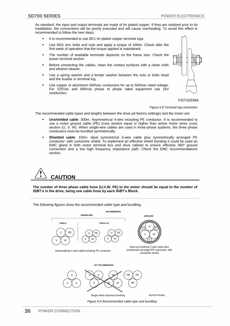
The recommended cable types and lengths between the drive (at factory settings) and the motor are:
Unshielded cable: 300m. Asymmetrical 4-wire including PE conductor. It is recommended to use a motor ground cable (PE) cross section equal or higher than active motor wires cross section (U, V, W). When single-wire cables are used in three-phase systems, the three phase conductors must be bundled symmetrically.
Shielded cable: 150m. Ideal symmetrical 3-wire cable plus symmetrically arranged PE conductor- with concentric shield. To implement an effective shield bonding it could be used an EMC gland in both motor terminal box and drive cabinet to ensure effective 360º ground connection and a low high frequency impedance path. Check the EMC recommendations section.
CAUTION
The number of three phase cable hose (U,V,W, PE) to the motor should be equal to the number of IGBT’s in the drive, being one cable hose by each IGBT’s Block.
The following figures show the recommended cable type and bundling.
Figure 6.9 Recommended cable type and bundling
POWER ELECTRONICS SD700 SERIES
POWER CONNECTION 37
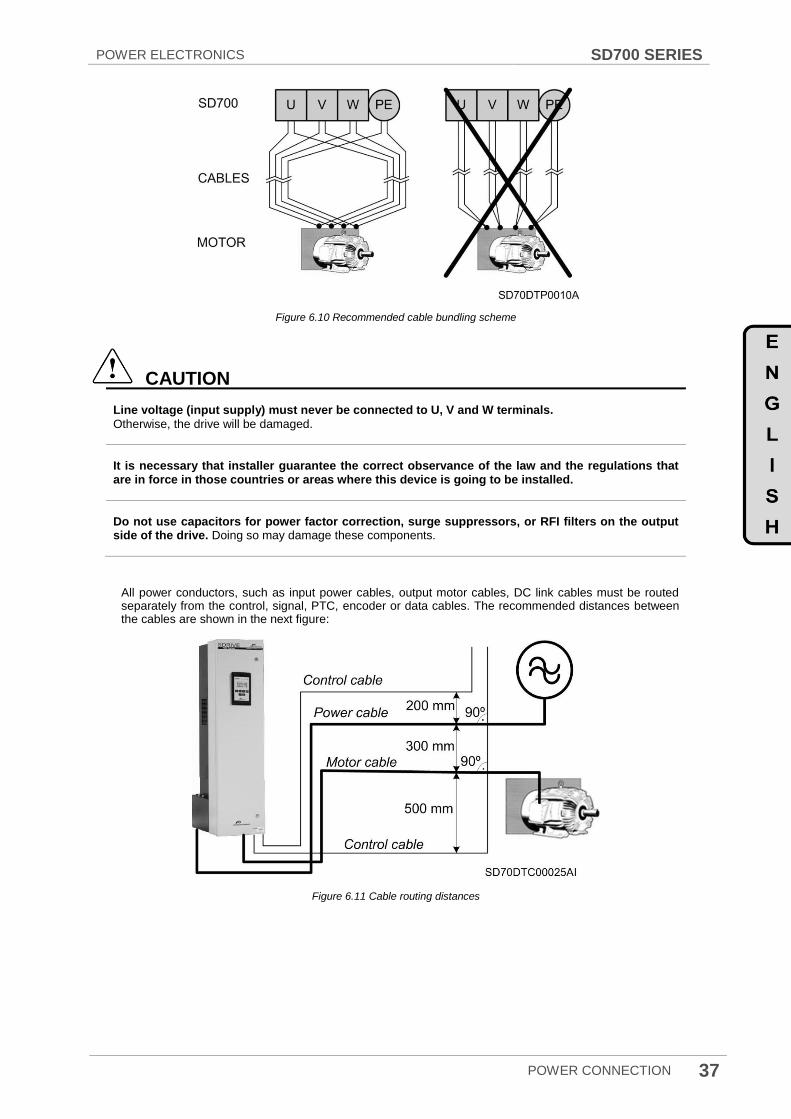
Figure 6.10 Recommended cable bundling scheme
CAUTION
Line voltage (input supply) must never be connected to U, V and W terminals.
Otherwise, the drive will be damaged.
It is necessary that installer guarantee the correct observance of the law and the regulations that are in force in those countries or areas where this device is going to be installed.
Do not use capacitors for power factor correction, surge suppressors, or RFI filters on the output side of the drive. Doing so may damage these components.
All power conductors, such as input power cables, output motor cables, DC link cables must be routed separately from the control, signal, PTC, encoder or data cables. The recommended distances between the cables are shown in the next figure:
Figure 6.11 Cable routing distances
SD700 SERIES POWER ELECTRONICS
38 POWER CONNECTION
It is recommended to route in separately cable racks, trays or ducts, the following cable types:
Single-wire signal or data cables with V< 60V
Single wire cable with 60V<V< 230V
Input power cables with low level of interferences 230V<V<1000V
Output motor power cables and Dynamic brake DC cables with high level of interferences 230V<V<1000V.
Medium voltage cables with V<1000V
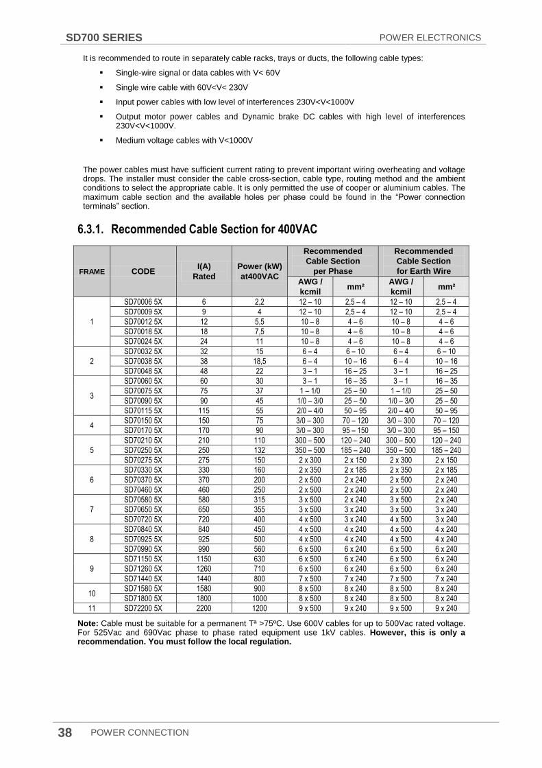
The power cables must have sufficient current rating to prevent important wiring overheating and voltage drops. The installer must consider the cable cross-section, cable type, routing method and the ambient conditions to select the appropriate cable. It is only permitted the use of cooper or aluminium cables. The maximum cable section and the available holes per phase could be found in the “Power connection terminals” section.
6.3.1. Recommended Cable Section for 400VAC
FRAME CODE I(A)
Rated
Power (kW)
at400VAC
Recommended
Cable Section
per Phase
Recommended
Cable Section
for Earth Wire
AWG /
kcmil mm²
AWG /
kcmil mm²
1
SD70006 5X 6 2,2 12 – 10 2,5 – 4 12 – 10 2,5 – 4
SD70009 5X 9 4 12 – 10 2,5 – 4 12 – 10 2,5 – 4
SD70012 5X 12 5,5 10 – 8 4 – 6 10 – 8 4 – 6
SD70018 5X 18 7,5 10 – 8 4 – 6 10 – 8 4 – 6
SD70024 5X 24 11 10 – 8 4 – 6 10 – 8 4 – 6
2
SD70032 5X 32 15 6 – 4 6 – 10 6 – 4 6 – 10
SD70038 5X 38 18,5 6 – 4 10 – 16 6 – 4 10 – 16
SD70048 5X 48 22 3 – 1 16 – 25 3 – 1 16 – 25
3
SD70060 5X 60 30 3 – 1 16 – 35 3 – 1 16 – 35
SD70075 5X 75 37 1 – 1/0 25 – 50 1 – 1/0 25 – 50
SD70090 5X 90 45 1/0 – 3/0 25 – 50 1/0 – 3/0 25 – 50
SD70115 5X 115 55 2/0 – 4/0 50 – 95 2/0 – 4/0 50 – 95
4 SD70150 5X 150 75 3/0 – 300 70 – 120 3/0 – 300 70 – 120
SD70170 5X 170 90 3/0 – 300 95 – 150 3/0 – 300 95 – 150
5
SD70210 5X 210 110 300 – 500 120 – 240 300 – 500 120 – 240
SD70250 5X 250 132 350 – 500 185 – 240 350 – 500 185 – 240
SD70275 5X 275 150 2 x 300 2 x 150 2 x 300 2 x 150
6
SD70330 5X 330 160 2 x 350 2 x 185 2 x 350 2 x 185
SD70370 5X 370 200 2 x 500 2 x 240 2 x 500 2 x 240
SD70460 5X 460 250 2 x 500 2 x 240 2 x 500 2 x 240
7
SD70580 5X 580 315 3 x 500 2 x 240 3 x 500 2 x 240
SD70650 5X 650 355 3 x 500 3 x 240 3 x 500 3 x 240
SD70720 5X 720 400 4 x 500 3 x 240 4 x 500 3 x 240
8
SD70840 5X 840 450 4 x 500 4 x 240 4 x 500 4 x 240
SD70925 5X 925 500 4 x 500 4 x 240 4 x 500 4 x 240
SD70990 5X 990 560 6 x 500 6 x 240 6 x 500 6 x 240
9
SD71150 5X 1150 630 6 x 500 6 x 240 6 x 500 6 x 240
SD71260 5X 1260 710 6 x 500 6 x 240 6 x 500 6 x 240
SD71440 5X 1440 800 7 x 500 7 x 240 7 x 500 7 x 240
10 SD71580 5X 1580 900 8 x 500 8 x 240 8 x 500 8 x 240
SD71800 5X 1800 1000 8 x 500 8 x 240 8 x 500 8 x 240
11 SD72200 5X 2200 1200 9 x 500 9 x 240 9 x 500 9 x 240
Note: Cable must be suitable for a permanent Tª >75ºC. Use 600V cables for up to 500Vac rated voltage. For 525Vac and 690Vac phase to phase rated equipment use 1kV cables. However, this is only a recommendation. You must follow the local regulation.
POWER ELECTRONICS SD700 SERIES
POWER CONNECTION 39
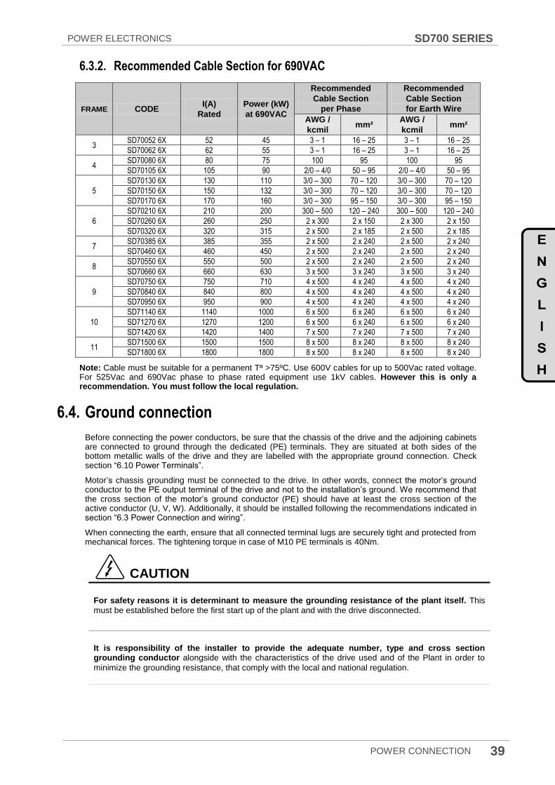
6.3.2. Recommended Cable Section for 690VAC
FRAME CODE I(A)
Rated
Power (kW)
at 690VAC
Recommended
Cable Section
per Phase
Recommended
Cable Section
for Earth Wire
AWG /
kcmil mm²
AWG /
kcmil mm²
3 SD70052 6X 52 45 3 – 1 16 – 25 3 – 1 16 – 25
SD70062 6X 62 55 3 – 1 16 – 25 3 – 1 16 – 25
4 SD70080 6X 80 75 100 95 100 95
SD70105 6X 10⁵ 90 2/0 – 4/0 50 – 95 2/0 – 4/0 50 – 95
5
SD70130 6X 130 110 3/0 – 300 70 – 120 3/0 – 300 70 – 120
SD70150 6X 150 132 3/0 – 300 70 – 120 3/0 – 300 70 – 120
SD70170 6X 170 160 3/0 – 300 95 – 150 3/0 – 300 95 – 150
6
SD70210 6X 210 200 300 – 500 120 – 240 300 – 500 120 – 240
SD70260 6X 260 250 2 x 300 2 x 150 2 x 300 2 x 150
SD70320 6X 320 315 2 x 500 2 x 185 2 x 500 2 x 185
7 SD70385 6X 385 355 2 x 500 2 x 240 2 x 500 2 x 240
SD70460 6X 460 450 2 x 500 2 x 240 2 x 500 2 x 240
8 SD70550 6X 550 500 2 x 500 2 x 240 2 x 500 2 x 240
SD70660 6X 660 630 3 x 500 3 x 240 3 x 500 3 x 240
9
SD70750 6X 750 710 4 x 500 4 x 240 4 x 500 4 x 240
SD70840 6X 840 800 4 x 500 4 x 240 4 x 500 4 x 240
SD70950 6X 950 900 4 x 500 4 x 240 4 x 500 4 x 240
10
SD71140 6X 1140 1000 6 x 500 6 x 240 6 x 500 6 x 240
SD71270 6X 1270 1200 6 x 500 6 x 240 6 x 500 6 x 240
SD71420 6X 1420 1400 7 x 500 7 x 240 7 x 500 7 x 240
11 SD71500 6X 1500 1500 8 x 500 8 x 240 8 x 500 8 x 240
SD71800 6X 1800 1800 8 x 500 8 x 240 8 x 500 8 x 240
Note: Cable must be suitable for a permanent Tª >75ºC. Use 600V cables for up to 500Vac rated voltage. For 525Vac and 690Vac phase to phase rated equipment use 1kV cables. However this is only a recommendation. You must follow the local regulation.
6.4. Ground connection
Before connecting the power conductors, be sure that the chassis of the drive and the adjoining cabinets are connected to ground through the dedicated (PE) terminals. They are situated at both sides of the bottom metallic walls of the drive and they are labelled with the appropriate ground connection. Check section “6.10 Power Terminals”.
Motor‟s chassis grounding must be connected to the drive. In other words, connect the motor‟s ground conductor to the PE output terminal of the drive and not to the installation‟s ground. We recommend that the cross section of the motor‟s ground conductor (PE) should have at least the cross section of the active conductor (U, V, W). Additionally, it should be installed following the recommendations indicated in section “6.3 Power Connection and wiring”.
When connecting the earth, ensure that all connected terminal lugs are securely tight and protected from mechanical forces. The tightening torque in case of M10 PE terminals is 40Nm.
CAUTION
For safety reasons it is determinant to measure the grounding resistance of the plant itself. This
must be established before the first start up of the plant and with the drive disconnected.
It is responsibility of the installer to provide the adequate number, type and cross section grounding conductor alongside with the characteristics of the drive used and of the Plant in order to
minimize the grounding resistance, that comply with the local and national regulation.
SD700 SERIES POWER ELECTRONICS
40 POWER CONNECTION
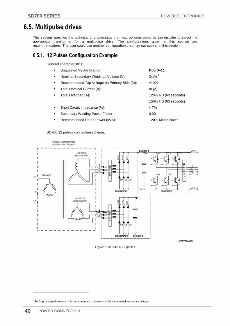
6.5. Multipulse drives
This section specifies the technical characteristics that may be considered by the installer to select the appropriate transformer for a multipulse drive. The configurations given in this section are recommendations. The user could use another configuration that may not appear in this section.
6.5.1. 12 Pulses Configuration Example
General characteristics:
Suggested Vector Diagram: Dd0/Dy11
Nominal Secondary Windings Voltage (V): 3xVn 1
Recommended Tap Voltage on Primary Side (%): ±10%
Total Nominal Current (A): In (A)
Total Overload (A): 120% ND (60 seconds)
150% HD (60 seconds)
Short Circuit Impedance (%): < 7%
Secondary Winding Power Factor: 0.90
Recommended Rated Power (kVA): +20% Motor Power
SD700 12 pulses connection scheme:
Figure 6.12 SD700 12 pulses
1 For improved performance, it is recommended to increase a 3% the nominal secondary voltage.
POWER ELECTRONICS SD700 SERIES
POWER CONNECTION 41
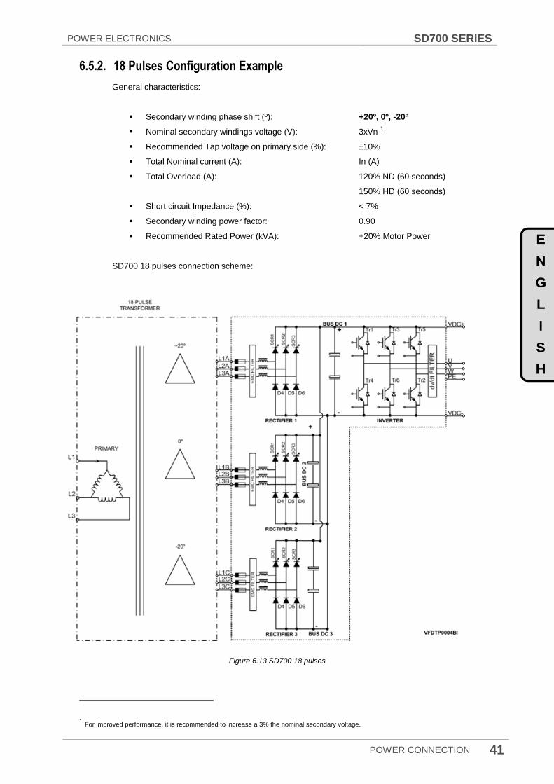
6.5.2. 18 Pulses Configuration Example
General characteristics:
Secondary winding phase shift (º): +20º, 0º, -20º
Nominal secondary windings voltage (V): 3xVn 1
Recommended Tap voltage on primary side (%): ±10%
Total Nominal current (A): In (A)
Total Overload (A): 120% ND (60 seconds)
150% HD (60 seconds)
Short circuit Impedance (%): < 7%
Secondary winding power factor: 0.90
Recommended Rated Power (kVA): +20% Motor Power
SD700 18 pulses connection scheme:
Figure 6.13 SD700 18 pulses
1 For improved performance, it is recommended to increase a 3% the nominal secondary voltage.

SD700 SERIES POWER ELECTRONICS
42 POWER CONNECTION
6.5.3. 24 Pulses Configuration Example
General characteristics:
Suggested Vector Diagram: D(-7.5)d0/D(-7.5)y11 D(+7.5)d0/D(+7.5)y11
Nominal secondary windings voltage (V): 3xVn 1
Recommended Tap voltage on primary side (%): ±10%
Total Nominal current (A): In (A)
Total Overload (A): 120% ND (60 seconds)
150% HD (60 seconds)
Short circuit Impedance (%): < 7%
Secondary winding power factor: 0.90
Recommended Rated Power (kVA): +20% Motor Power
SD700 24 pulses connection scheme:
Figure 6.14 SD700 24 pulses
1 For improved performance, it is recommended to increase a 3% the nominal secondary voltage.
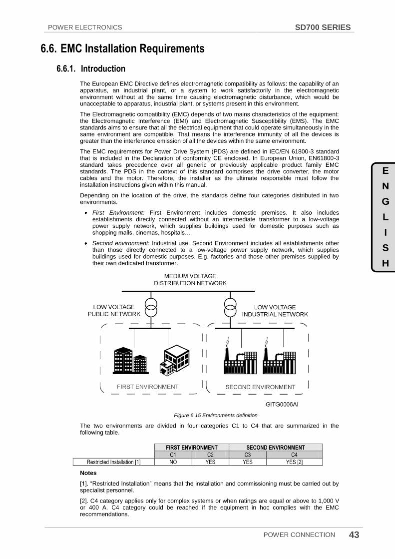
POWER ELECTRONICS SD700 SERIES
POWER CONNECTION 43
6.6. EMC Installation Requirements
6.6.1. Introduction
The European EMC Directive defines electromagnetic compatibility as follows: the capability of an apparatus, an industrial plant, or a system to work satisfactorily in the electromagnetic environment without at the same time causing electromagnetic disturbance, which would be unacceptable to apparatus, industrial plant, or systems present in this environment.
The Electromagnetic compatibility (EMC) depends of two mains characteristics of the equipment: the Electromagnetic Interference (EMI) and Electromagnetic Susceptibility (EMS). The EMC standards aims to ensure that all the electrical equipment that could operate simultaneously in the same environment are compatible. That means the interference immunity of all the devices is greater than the interference emission of all the devices within the same environment.
The EMC requirements for Power Drive System (PDS) are defined in IEC/EN 61800-3 standard that is included in the Declaration of conformity CE enclosed. In European Union, EN61800-3 standard takes precedence over all generic or previously applicable product family EMC standards. The PDS in the context of this standard comprises the drive converter, the motor cables and the motor. Therefore, the installer as the ultimate responsible must follow the installation instructions given within this manual.
Depending on the location of the drive, the standards define four categories distributed in two environments.
First Environment: First Environment includes domestic premises. It also includes establishments directly connected without an intermediate transformer to a low-voltage power supply network, which supplies buildings used for domestic purposes such as shopping malls, cinemas, hospitals…
Second environment: Industrial use. Second Environment includes all establishments other than those directly connected to a low-voltage power supply network, which supplies buildings used for domestic purposes. E.g. factories and those other premises supplied by their own dedicated transformer.
Figure 6.15 Environments definition
The two environments are divided in four categories C1 to C4 that are summarized in the following table.
FIRST ENVIRONMENT SECOND ENVIRONMENT
C1 C2 C3 C4
Restricted Installation [1] NO YES YES YES [2]
Notes
[1]. “Restricted Installation” means that the installation and commissioning must be carried out by specialist personnel.
[2]. C4 category applies only for complex systems or when ratings are equal or above to 1,000 V or 400 A. C4 category could be reached if the equipment in hoc complies with the EMC recommendations.

SD700 SERIES POWER ELECTRONICS
44 POWER CONNECTION
6.6.2. SD700 compliance
SD700 variable speed drives are designed for industrial (second environment) use. The use of radio frequency interference filters (RFI filters) and dV/dt filters as standard, and the correct installation following the recommendations within this manual, permits to achieve compliance with C3 category defined in IEC/EN 61800-3.
Optionally the SD700 non-floating earth variable speed drive could be installed in residential areas (first environment) by employing optional RFI filters that permits to achieve compliance with C2 category.
SD700 is not a retail unit, which is neither a plug in device nor a movable device and it is intended to be installed and commissioned by qualified personnel. Therefore, C1 category will not be required.
SD700 with floating earth configuration can be installed in Industrial (Second Environment) IT grids. Although they do not integrate normal RFI filters, following the installation recommendation within this manual and its dV/dt filter as standard, permits to achieve compliance with C3 category defined in IEC/EN61800-3.
6.6.3. Connection
SD700 do not require the use of shielded motor cable to achieve compliance with C3 category, when a correct installation is made. Wiring and Installation recommendations are included in sections “6.3 Power Connection and wiring” and “6.4 Ground connection”.
It is recommended to implement a 360º contact that creates an effective shield bonding in both the SD700 cabinet and the motor terminal box. As an example, it could be installed EMC cable glands as shown in the next figure.
Figure 6.16 Correct output motor cables shield bonding
It is recommended for control signals to use shielded cable and to follow recommendations included in section ”7.1 Wiring recommendations”.
CAUTION
Select communication and control system according to the drive EMC environment. Otherwise,
systems could suffer from interferences due to a low EMS level.
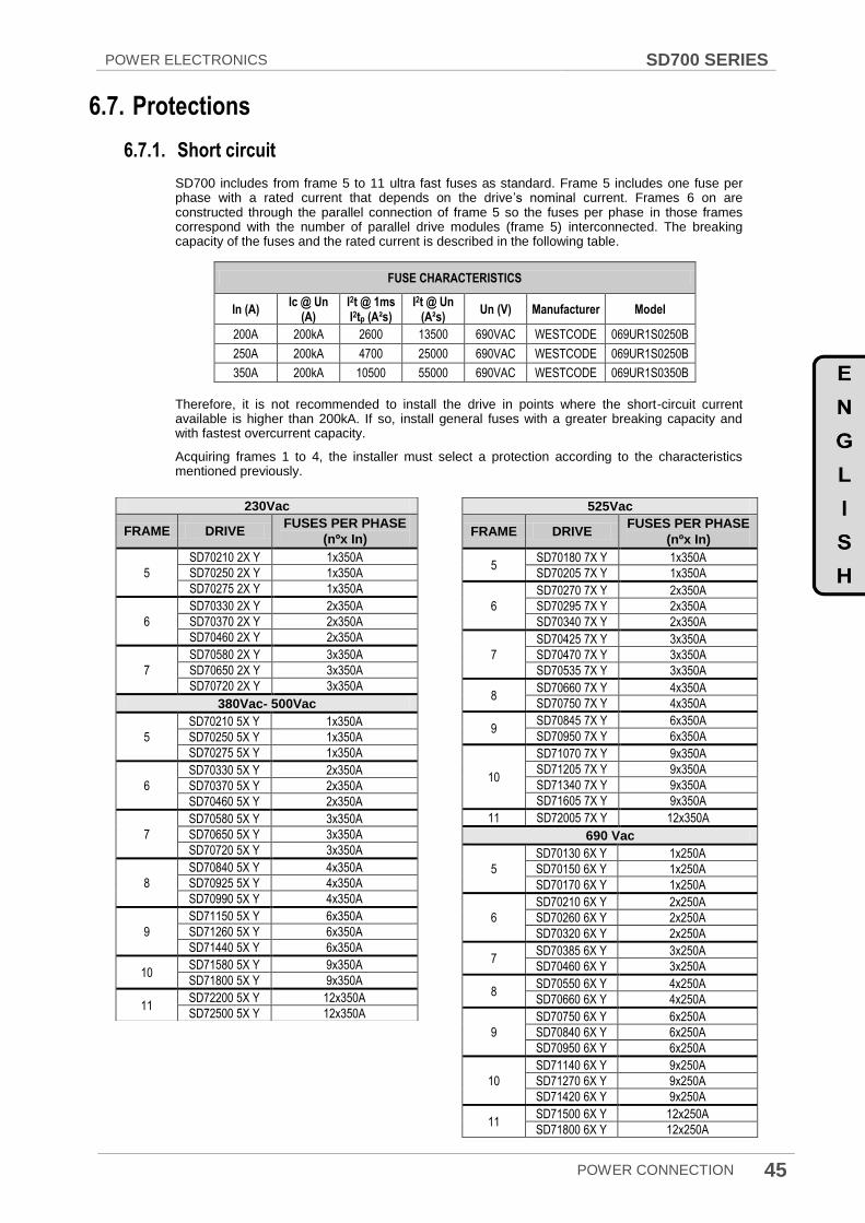
POWER ELECTRONICS SD700 SERIES
POWER CONNECTION 45
6.7. Protections
6.7.1. Short circuit
SD700 includes from frame 5 to 11 ultra fast fuses as standard. Frame 5 includes one fuse per phase with a rated current that depends on the drive‟s nominal current. Frames 6 on are constructed through the parallel connection of frame 5 so the fuses per phase in those frames correspond with the number of parallel drive modules (frame 5) interconnected. The breaking capacity of the fuses and the rated current is described in the following table.
Therefore, it is not recommended to install the drive in points where the short-circuit current available is higher than 200kA. If so, install general fuses with a greater breaking capacity and with fastest overcurrent capacity.
Acquiring frames 1 to 4, the installer must select a protection according to the characteristics mentioned previously.
FUSE CHARACTERISTICS
In (A) Ic @ Un
(A) I2t @ 1ms I2tp (A²s)
I2t @ Un (A²s)
Un (V) Manufacturer Model
200A 200kA 2600 13500 690VAC WESTCODE 069UR1S0250B
250A 200kA 4700 25000 690VAC WESTCODE 069UR1S0250B
350A 200kA 10500 55000 690VAC WESTCODE 069UR1S0350B
525Vac
FRAME DRIVE FUSES PER PHASE
(nºx In)
5 SD70180 7X Y 1x350A
SD70205 7X Y 1x350A
6
SD70270 7X Y 2x350A
SD70295 7X Y 2x350A
SD70340 7X Y 2x350A
7
SD70425 7X Y 3x350A
SD70470 7X Y 3x350A
SD70535 7X Y 3x350A
8 SD70660 7X Y 4x350A
SD70750 7X Y 4x350A
9 SD70845 7X Y 6x350A
SD70950 7X Y 6x350A
10
SD71070 7X Y 9x350A
SD71205 7X Y 9x350A
SD71340 7X Y 9x350A
SD71605 7X Y 9x350A
11 SD72005 7X Y 12x350A
690 Vac
5
SD70130 6X Y 1x250A
SD70150 6X Y 1x250A
SD70170 6X Y 1x250A
6
SD70210 6X Y 2x250A
SD70260 6X Y 2x250A
SD70320 6X Y 2x250A
7 SD70385 6X Y 3x250A
SD70460 6X Y 3x250A
8 SD70550 6X Y 4x250A
SD70660 6X Y 4x250A
9
SD70750 6X Y 6x250A
SD70840 6X Y 6x250A
SD70950 6X Y 6x250A
10
SD71140 6X Y 9x250A
SD71270 6X Y 9x250A
SD71420 6X Y 9x250A
11 SD71500 6X Y 12x250A
SD71800 6X Y 12x250A
230Vac
FRAME DRIVE FUSES PER PHASE
(nºx In)
5
SD70210 2X Y 1x350A
SD70250 2X Y 1x350A
SD70275 2X Y 1x350A
6
SD70330 2X Y 2x350A
SD70370 2X Y 2x350A
SD70460 2X Y 2x350A
7
SD70580 2X Y 3x350A
SD70650 2X Y 3x350A
SD70720 2X Y 3x350A
380Vac- 500Vac
5
SD70210 5X Y 1x350A
SD70250 5X Y 1x350A
SD70275 5X Y 1x350A
6
SD70330 5X Y 2x350A
SD70370 5X Y 2x350A
SD70460 5X Y 2x350A
7
SD70580 5X Y 3x350A
SD70650 5X Y 3x350A
SD70720 5X Y 3x350A
8
SD70840 5X Y 4x350A
SD70925 5X Y 4x350A
SD70990 5X Y 4x350A
9
SD71150 5X Y 6x350A
SD71260 5X Y 6x350A
SD71440 5X Y 6x350A
10 SD71580 5X Y 9x350A
SD71800 5X Y 9x350A
11 SD72200 5X Y 12x350A
SD72500 5X Y 12x350A
SD700 SERIES POWER ELECTRONICS
46 POWER CONNECTION
6.7.2. Ground fault protection
The drive is equipped with an internal software ground fault protective function to protect the drive against input and output unbalanced currents. The response threshold can be set from 0% to 30% of the rated current (G.11.3). For further information, see Programming and Software Manual.
This function is not intended to work as a personnel safety or fire protection, so an external protection must be provided to ensure that a substantial ground fault current is promptly interrupted. The SD700 drives are suitable to operate with RCD components Type B, if it is required. The EMC filters and long motor cables increase the ground leakage currents so the threshold response of the protection should be adjusted according to the relevant plant conditions. For additional information, contact with Power Electronics.
6.7.3. Motor thermal protection
The drive includes a motor thermal protection that based on the motor performance parameters mathematically calculates the thermal reservoir of the motor. When this reservoir is reduced below the limits, the drive automatically stops the motor. The thermal model sensitivity could be configured in parameter G2.7, for further information consult Software and programming manual.
The drive includes as standard a PTC connection that permits to monitor the motor temperature. Once connected and configured the drive could either stop the motor or generate a warning signal.
6.7.4. Others
The drive implements additional motor and drive protections such as power-loss ride through, automatic fly restart, high and low input and output voltage, pump overload and underload... For further information, consult Software and Programming manual.
6.7.5. Safety Stop Function
Safe Torque Off (STO) allows the drive output to be disabled so that the drive cannot provide power or generate torque in the motor. The STO safety function has been certified by Tüv Rheinland according to IEC/EN 61800-5-2. For further information, see section 7.3.
6.8. IT grids - floating earth drives
When planning an IT grid electrical installation select the drive for floating earth operation. Check the drive reference to ensure the correct drive selection.
IT grids must be equipped with an insulation monitoring system. To set the parameter settings, consider that the drive has inherent very high impedance, even when a large number of drives are working in parallel on the same IT system.
It is recommended the installation of surge arrester to ground to protect against transient overvoltages. The surge arrester must have rated voltage greater than the drive voltage range to prevent its operation during normal conditions.

POWER ELECTRONICS SD700 SERIES
POWER CONNECTION 47
6.9. Dynamic Braking Resistors for Equipments of Frames 1 and 2
The equipments of Frames 1 and 2 include the built-in dynamic brake as standard. The user should only connect a resistor between terminals +HVDC and B, as the following drawing shows.
Figure 6.17 Power electronics for equipments of Frames 1 and 2
6.9.1. Resistor Values for Dynamic Brake (Optional)
FRAME CODE I(A) Rated
Motor Power
(kW) at
400VAC
Dynamic
Braking
Resistor (Ω)
Power of
Braking
Resistor (kW)
1
SD70006 5X 6 2,2 250 2,2
SD70009 5X 9 4 140 4
SD70012 5X 12 5,5 100 5,5
SD70018 5X 18 7,5 75 7,5
SD70024 5X 24 11 50 11
2
SD70032 5X 32 15 40 15
SD70038 5X 38 18,5 30 18,5
SD70048 5X 48 22 25 22
Note: This table is based on ED (Enable Duty) of 100%. For other ED‟s different than 100%, it will be used braking resistor with the same value in ohms and their power will be calculated by multiplying their power value at 100% (table value) by the new ED. Enable Duty means the time operated by the resistor (regeneration). Resistors for 100% of ED = continuous operation. For example, in case of ED of 30%, it will be multiplied by 0.3.

SD700 SERIES POWER ELECTRONICS
48 POWER CONNECTION
6.9.2. Terminals of the Resistor for Dynamic Brake
The terminals of the braking resistors are:
TERMINAL DESCRIPTION
B1, B2 Connection terminals to connect the resistor to the terminals of the dynamic brake built in the drive.
TH1, TH2 [1]
Thermal sensor of the resistor. The status of which will change according to the temperature. - For normal temperature (ambient): Normally closed (NC) (TH1 – TH2 closed contact). - In case of resistor over temperature: Normally open (NO) (TH1 – TH2 open contact). Connect this signal to a terminal of one digital input of the drive configured as ‘external fault’.
[1]
Terminals TH1 and TH2 will be available when the used braking resistor is equipped with thermal sensor.
Note: It is recommended to use braking resistors equipped with thermal sensors. Connect it to one digital input of the drive and configure this input as „external fault‟.
6.9.3. Connection Drawing
The connection between the optional external resistor for the built-in dynamic brake and the drive is shown in the following figure.
Figure 6.18 Connection drawing of the resistor for the dynamic brake in equipments of Frames 1 and 2
Notes:
The braking resistor should be non-inductive.
To connect the sensor to the drive, it is recommended to use shielded cable.
The maximum cable length between the drive and the external braking resistor is 20m. For other configurations, contact with Power Electronics.
CAUTION Do not touch the braking resistor during the drive operation since it could be very hot (more than 150ºC).

POWER ELECTRONICS SD700 SERIES
POWER CONNECTION 49
6.10. Power terminals
6.10.1. Connections for Frame 1
Figure 6.19 Location of power connections for equipments of Frame 1 [mm]

SD700 SERIES POWER ELECTRONICS
50 POWER CONNECTION
6.10.2. Connections for Frame 2
Figure 6.20 Location of power connections for equipments of Frame 2 [mm]
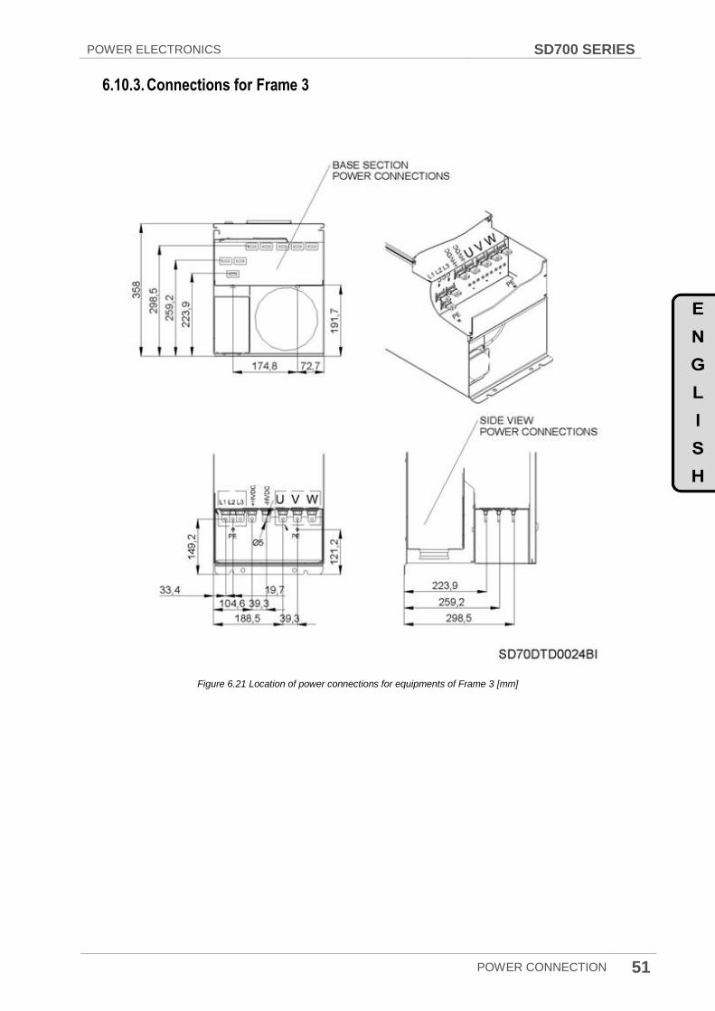
POWER ELECTRONICS SD700 SERIES
POWER CONNECTION 51
6.10.3. Connections for Frame 3
Figure 6.21 Location of power connections for equipments of Frame 3 [mm]

SD700 SERIES POWER ELECTRONICS
52 POWER CONNECTION
6.10.4. Connections for Frame 4
Figure 6.22 Location of power connections for equipments of Frame 4 [mm]

POWER ELECTRONICS SD700 SERIES
POWER CONNECTION 53
6.10.5. Connections for Frame 5
Figure 6.23 Location of power connections for equipments of Frame 5 [mm]
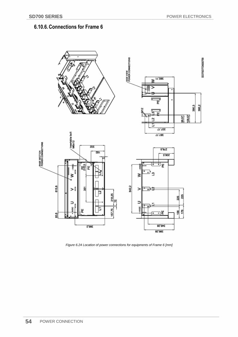
SD700 SERIES POWER ELECTRONICS
54 POWER CONNECTION
6.10.6. Connections for Frame 6
Figure 6.24 Location of power connections for equipments of Frame 6 [mm]
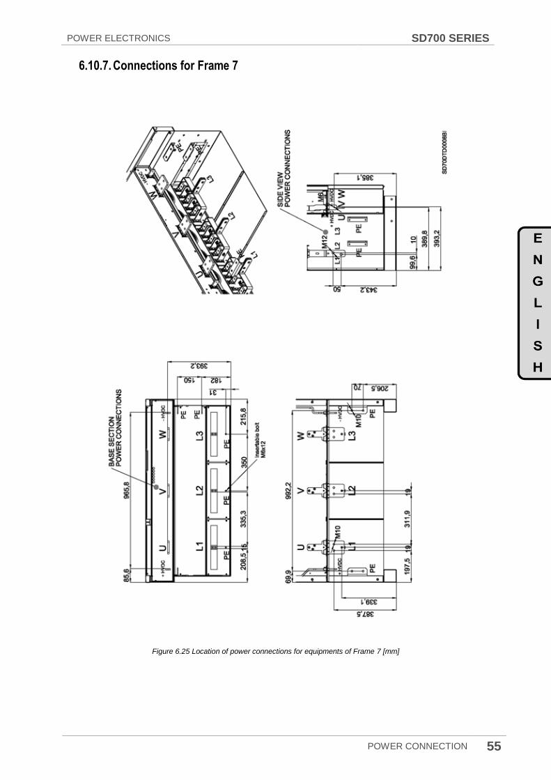
POWER ELECTRONICS SD700 SERIES
POWER CONNECTION 55
6.10.7. Connections for Frame 7
Figure 6.25 Location of power connections for equipments of Frame 7 [mm]

SD700 SERIES POWER ELECTRONICS
56 POWER CONNECTION
6.10.8. Connections for Frame 8
Figure 6.26 Location of power connections for equipments of Frame 8 [mm]
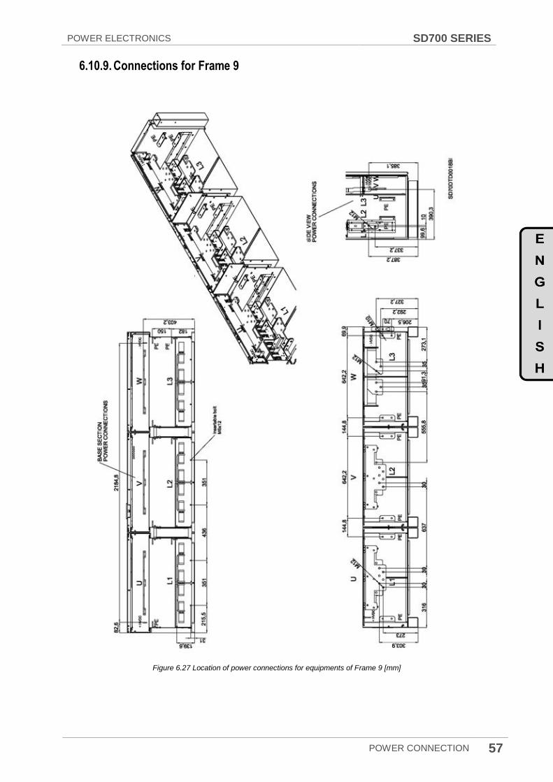
POWER ELECTRONICS SD700 SERIES
POWER CONNECTION 57
6.10.9. Connections for Frame 9
Figure 6.27 Location of power connections for equipments of Frame 9 [mm]

SD700 SERIES POWER ELECTRONICS
58 POWER CONNECTION
6.10.10. Connections for Frame 10
Figure 6.28 Location of power connections for equipments of Frame 10 [mm]

POWER ELECTRONICS SD700 SERIES
POWER CONNECTION 59
6.10.11. Connections for Frame 11
Figure 6.29 Location of power connections for equipments of Frame 11 [mm]
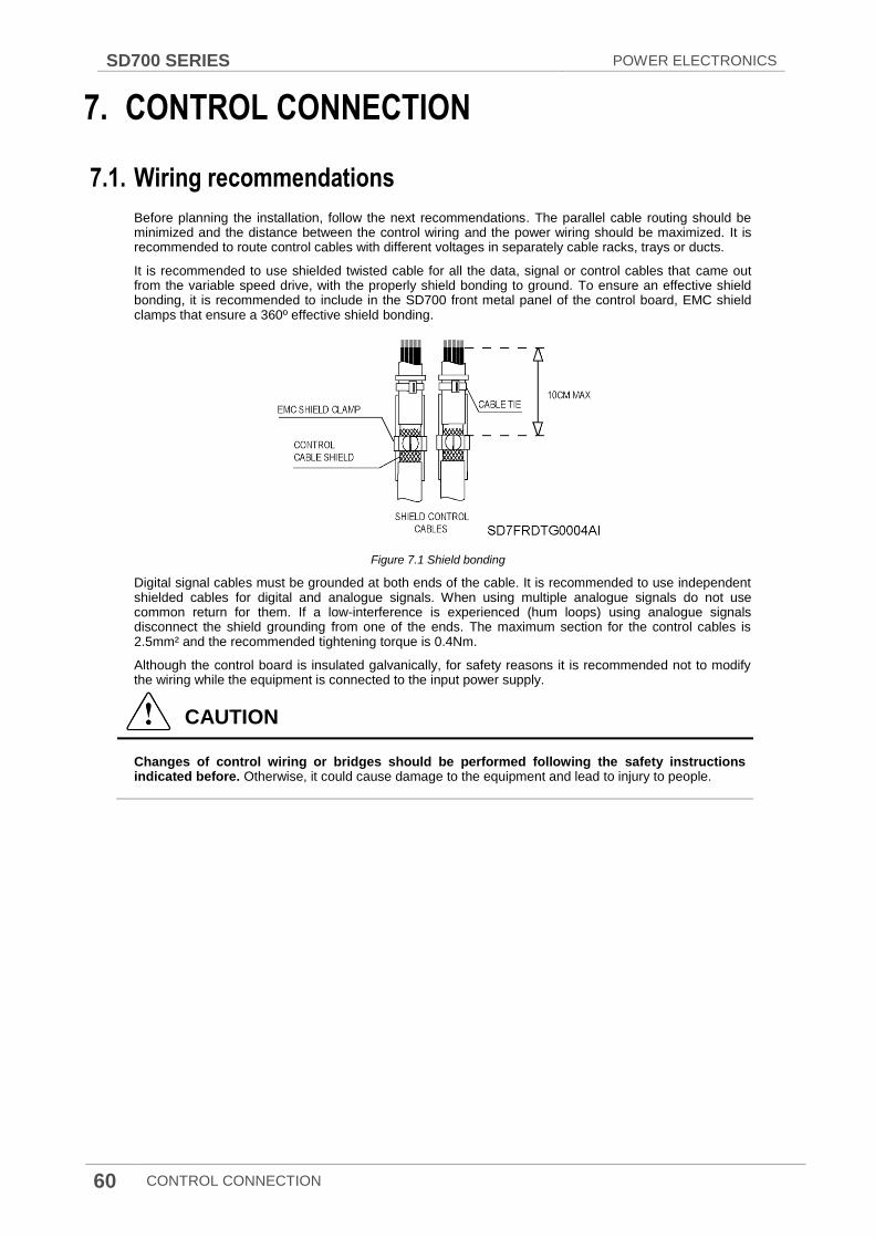
SD700 SERIES POWER ELECTRONICS
60 CONTROL CONNECTION
7. CONTROL CONNECTION
7.1. Wiring recommendations
Before planning the installation, follow the next recommendations. The parallel cable routing should be minimized and the distance between the control wiring and the power wiring should be maximized. It is recommended to route control cables with different voltages in separately cable racks, trays or ducts.
It is recommended to use shielded twisted cable for all the data, signal or control cables that came out from the variable speed drive, with the properly shield bonding to ground. To ensure an effective shield bonding, it is recommended to include in the SD700 front metal panel of the control board, EMC shield clamps that ensure a 360º effective shield bonding.
Figure 7.1 Shield bonding
Digital signal cables must be grounded at both ends of the cable. It is recommended to use independent shielded cables for digital and analogue signals. When using multiple analogue signals do not use common return for them. If a low-interference is experienced (hum loops) using analogue signals disconnect the shield grounding from one of the ends. The maximum section for the control cables is 2.5mm² and the recommended tightening torque is 0.4Nm.
Although the control board is insulated galvanically, for safety reasons it is recommended not to modify the wiring while the equipment is connected to the input power supply.
CAUTION
Changes of control wiring or bridges should be performed following the safety instructions indicated before. Otherwise, it could cause damage to the equipment and lead to injury to people.

POWER ELECTRONICS SD700 SERIES
CONTROL CONNECTION 61
7.2. Control board terminals description
CAUTION
Changes of control wiring or bridges should be performed at least 10 minutes after disconnecting the input power and after checking the DC Link voltage is discharged with a meter (below 30VDC). Otherwise, you may get an electric shock.
Figure 7.2 Control board of SD700
The user will have only access to the inverter control board that is equipped with the user interface ports and connectors. It integrate as standard PTC connection, analogue inputs and outputs, digital inputs and outputs, DC external input power supplies, RS485, RS232 and USB communication and display ports. Moreover, the board is ready for the connection of optional boards such as I/O expansion board, encoder board, communication boards, fiber optic board, etc.
Figure 7.3 Location and description of user connectors
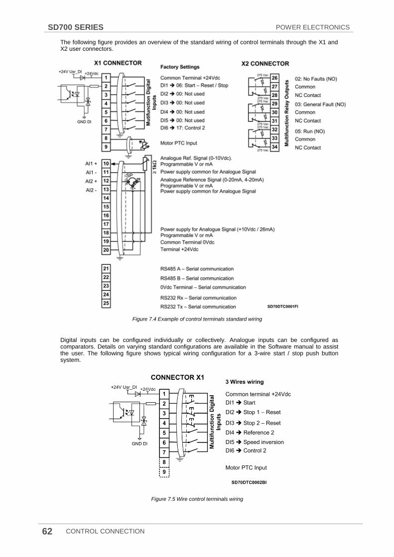
SD700 SERIES POWER ELECTRONICS
62 CONTROL CONNECTION
The following figure provides an overview of the standard wiring of control terminals through the X1 and X2 user connectors.
Figure 7.4 Example of control terminals standard wiring
Digital inputs can be configured individually or collectively. Analogue inputs can be configured as comparators. Details on varying standard configurations are available in the Software manual to assist the user. The following figure shows typical wiring configuration for a 3-wire start / stop push button system.
Figure 7.5 Wire control terminals wiring

POWER ELECTRONICS SD700 SERIES
CONTROL CONNECTION 63
X1 C
ON
NE
CT
OR
DIG
ITA
L I
NP
UT
S
PIN SIGNAL DESCRIPTION
1 +24V_USER Power supply for digital inputs. Short circuit and overload protected. (Maximum +24VDC, 180mA)
2 DI1
Programmable Digital Input 1. Digital inputs are configured in the Input group. Their status can be displayed in the visualisation group. It is powered from terminal 1 or an external power 24VDC supply. If an external power supply is used, the common should be connected to the terminal 19 (user GND).
3 DI2 Programmable Digital Input 2. See DI1 description.
4 DI3 Programmable Digital Input 3. See DI1 description.
5 DI4 Programmable Digital Input 4. See DI1 description.
6 DI5 Programmable Digital Input 5. See DI1 description.
7 DI6 Programmable Digital Input 6. See DI1 description.
8 PTC + Control signal of the motor temperature through the connection of a PTC.
9 PTC -
AN
AL
OG
UE
INP
UT
S 10 AI1 +
Voltage or current programmable Analogue Input 1 (V or mA). Configurable for 0-10VDC,
±10VDC, 0-20mA or 4-20mA. Input resistance value in voltage mode is Ri=20k . Input
resistance value in current mode is Ri=250 .
11 AI1 - Common for Analogue Input 1.
12 AI2 + Voltage or current programmable Analogue Input 2 (V or mA). See AI1 description.
13 AI2 - Common for Analogue Input 2.
AN
AL
OG
UE
OU
TP
UT
S
14 AO1 + Voltage or current programmable Analogue Output 1 (V or mA). Configurable for 0-10VDC, ±10VDC, 0-20mA or 4-20mA.
15 AO1 - Common for Analogue Output 1.
16 AO2 + Voltage or current programmable Analogue Output 2 (V or mA). Configurable for 0-10VDC, ±10VDC, 0-20mA or 4-20mA.
17 AO2 - Common for Analogue Output 2.
US
ER
PO
WE
R
SU
PP
LY
18 +10V_POT 10VDC power supply for analogue inputs. Input power for maximum 2 potentiometers (R≥1kΩ).
19 GND_USER Common for analogue inputs (0VDC).
20 +24V_USER User power supply. It provides a DC supply to an external sensor. (Maximum: +24VDC, 180mA).
SE
RIA
L
CO
MM
UN
ICA
TIO
N
21 RS485 A RS485 serial communication interface for Modbus.
22 RS485 B
23 RS Common Common for RS485 / RS232 serial communication signals.
24 RS232 Rx RS232 serial communication interface for Modbus.
25 RS232 Tx
X2 C
ON
NE
CT
OR
DIG
ITA
L O
UT
PU
TS
26 RLY1 NO Digital Output 1. Programmable change over relay (NO / NC). Potential free (Maximum: 250VAC, 8A; 30VDC, 8A).
27 RLY1 C
28 RLY1 NC
29 RLY2 NO Digital Output 2. Programmable change over relay (NO / NC). Potential free (Maximum: 250VAC, 8A; 30VDC, 8A).
30 RLY2 C
31 RLY2 NC
32 RLY3 NO Digital Output 3. Programmable change over relay (NO / NC). Potential free (Maximum: 250VAC, 8A; 30VDC, 8A).
33 RLY3 C
34 RLY3 NC
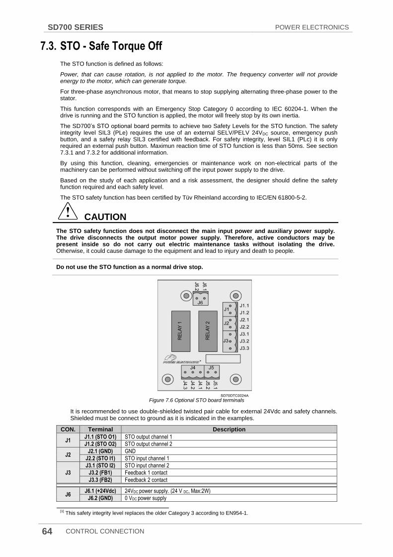
SD700 SERIES POWER ELECTRONICS
64 CONTROL CONNECTION
7.3. STO - Safe Torque Off
The STO function is defined as follows:
Power, that can cause rotation, is not applied to the motor. The frequency converter will not provide energy to the motor, which can generate torque.
For three-phase asynchronous motor, that means to stop supplying alternating three-phase power to the stator.
This function corresponds with an Emergency Stop Category 0 according to IEC 60204-1. When the drive is running and the STO function is applied, the motor will freely stop by its own inertia.
The SD700‟s STO optional board permits to achieve two Safety Levels for the STO function. The safety integrity level SIL3 (PLe) requires the use of an external SELV/PELV 24VDC source, emergency push button, and a safety relay SIL3 certified with feedback. For safety integrity, level SIL1 (PLc) it is only required an external push button. Maximun reaction time of STO function is less than 50ms. See section 7.3.1 and 7.3.2 for additional information.
By using this function, cleaning, emergencies or maintenance work on non-electrical parts of the machinery can be performed without switching off the input power supply to the drive.
Based on the study of each application and a risk assessment, the designer should define the safety function required and each safety level.
The STO safety function has been certified by Tüv Rheinland according to IEC/EN 61800-5-2.
CAUTION
The STO safety function does not disconnect the main input power and auxiliary power supply. The drive disconnects the output motor power supply. Therefore, active conductors may be present inside so do not carry out electric maintenance tasks without isolating the drive. Otherwise, it could cause damage to the equipment and lead to injury and death to people.
Do not use the STO function as a normal drive stop.
Figure 7.6 Optional STO board terminals
It is recommended to use double-shielded twisted pair cable for external 24Vdc and safety channels. Shielded must be connect to ground as it is indicated in the examples.
CON. Terminal Description
J1 J1.1 (STO O1) STO output channel 1
J1.2 (STO O2) STO output channel 2
J2 J2.1 (GND) GND
J2.2 (STO I1) STO input channel 1
J3
J3.1 (STO I2) STO input channel 2
J3.2 (FB1) Feedback 1 contact
J3.3 (FB2) Feedback 2 contact
J6 J6.1 (+24Vdc) 24VDC power supply. (24 V DC, Max:2W)
J6.2 (GND) 0 VDC power supply
[1] This safety integrity level replaces the older Category 3 according to EN954-1.
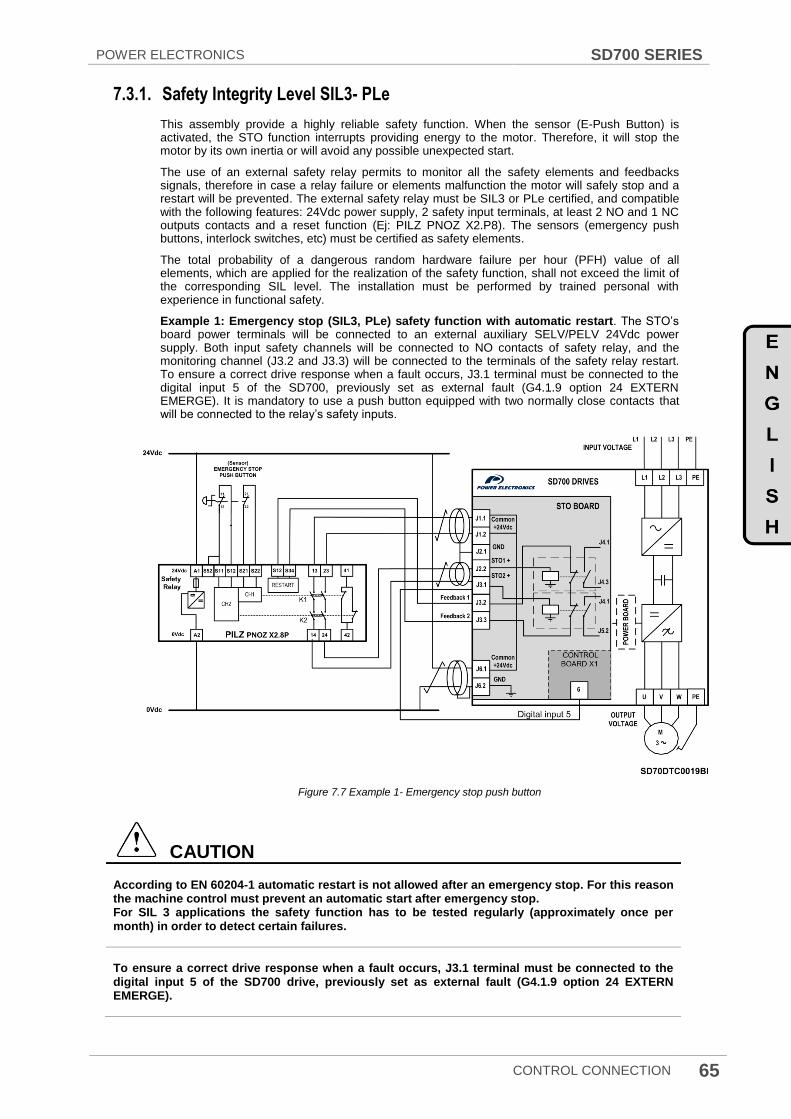
POWER ELECTRONICS SD700 SERIES
CONTROL CONNECTION 65
7.3.1. Safety Integrity Level SIL3- PLe
This assembly provide a highly reliable safety function. When the sensor (E-Push Button) is activated, the STO function interrupts providing energy to the motor. Therefore, it will stop the motor by its own inertia or will avoid any possible unexpected start.
The use of an external safety relay permits to monitor all the safety elements and feedbacks signals, therefore in case a relay failure or elements malfunction the motor will safely stop and a restart will be prevented. The external safety relay must be SIL3 or PLe certified, and compatible with the following features: 24Vdc power supply, 2 safety input terminals, at least 2 NO and 1 NC outputs contacts and a reset function (Ej: PILZ PNOZ X2.P8). The sensors (emergency push buttons, interlock switches, etc) must be certified as safety elements.
The total probability of a dangerous random hardware failure per hour (PFH) value of all elements, which are applied for the realization of the safety function, shall not exceed the limit of the corresponding SIL level. The installation must be performed by trained personal with experience in functional safety.
Example 1: Emergency stop (SIL3, PLe) safety function with automatic restart. The STO‟s board power terminals will be connected to an external auxiliary SELV/PELV 24Vdc power supply. Both input safety channels will be connected to NO contacts of safety relay, and the monitoring channel (J3.2 and J3.3) will be connected to the terminals of the safety relay restart. To ensure a correct drive response when a fault occurs, J3.1 terminal must be connected to the digital input 5 of the SD700, previously set as external fault (G4.1.9 option 24 EXTERN EMERGE). It is mandatory to use a push button equipped with two normally close contacts that will be connected to the relay‟s safety inputs.
Figure 7.7 Example 1- Emergency stop push button
CAUTION
According to EN 60204-1 automatic restart is not allowed after an emergency stop. For this reason the machine control must prevent an automatic start after emergency stop. For SIL 3 applications the safety function has to be tested regularly (approximately once per month) in order to detect certain failures.
To ensure a correct drive response when a fault occurs, J3.1 terminal must be connected to the digital input 5 of the SD700 drive, previously set as external fault (G4.1.9 option 24 EXTERN EMERGE).

SD700 SERIES POWER ELECTRONICS
66 CONTROL CONNECTION
Example 2: SIL3 (PLe) Safety door opening stop for maintenance tasks with manual restart. This function is used to prevent an unexpected restart when a maintenance task is being carried out in a risk area. In this case, the relay‟s safety inputs will be connected to a safety interlock switch placed in the door. Additionally a push button is installed to force a manual restart of the safety relay and a lamp connected to the NC output contact of the external safety relay will indicate the restart. To ensure a correct drive response when a fault occurs, J3.1 terminal must be connected to the digital input 5 of the SD700, previously set as external fault (G4.1.9 option 24 EXTERN EMERGE).
Figure 7.8 Example 2- Safety door opening
CAUTION For SIL 3 applications the safety function has to be tested regularly (approximately once per month) in order to detect certain failures.
To ensure a correct drive response when a fault occurs, J3.1 terminal must be connected to the digital input 5 of the SD700 drive, previously set as external fault (G4.1.9 option 24 EXTERN EMERGE).

POWER ELECTRONICS SD700 SERIES
CONTROL CONNECTION 67
7.3.2. Safety Integrity Level SIL1- PLc
This connection scheme provides an easy and cost effective solution for installations that not require the highest safety level requirements. In this case, the two NC contacts from the external push button are directly connected to the optional STO board. As the previous solutions, the operator pressing sensor will deactivates the IGBT switching of the inverter bridge through two independent channels, disconnecting the motor power supply and avoiding any possible unexpected restart. The monitoring terminals will not be connected. To ensure a correct drive response when a fault occurs, J3.1 terminal must be connected to the digital input 5 of the SD700, previously set as external fault (G4.1.9 option 24 EXTERN EMERGE).
Figure 7.9 Emergency Stop Push button connection scheme – SIL 1 -PLe
X1.19 and X1.20 terminals can be used for other purpose depending on the inverter applications (frequency reference performed by an external potentiometer, analogue feedback etc…). In order to avoid the multiple cable connection in a single terminal (X1.19, X1.20), it is recommended to add additional external terminals to distribute the power supply.
CAUTION
According to EN 60204-1 automatic restart is not allowed after an emergency stop. For this reason the machine control must prevent an automatic start after emergency stop.
To ensure a correct drive response when a fault occurs, J3.1 terminal must be connected to the digital input 5 of the SD700 drive, previously set as external fault (G4.1.9 option 24 EXTERN EMERGE).
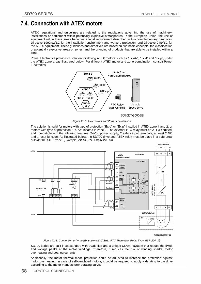
SD700 SERIES POWER ELECTRONICS
68 CONTROL CONNECTION
7.4. Connection with ATEX motors
ATEX regulations and guidelines are related to the regulations governing the use of machinery, installations or equipment within potentially explosive atmospheres. In the European Union, the use of equipment within these areas becomes a legal requirement described in two complementary directives: Directive 1999/92/EC for the installation environment and workers protection, and Directive 94/9/EC for the ATEX equipment. These guidelines and directives are based on two basic concepts: the classification of potentially explosive areas or zones, and the branding of products that are able to be installed within a zone.
Power Electronics provides a solution for driving ATEX motors such as “Ex nA”, “Ex d” and “Ex p”, under the ATEX zone areas illustrated below. For different ATEX motor and zone combination, consult Power Electronics.
Figure 7.10: Atex motors and Zones combination
The solution is valid for motors with type of protection "Ex d" or “Ex p” installed in ATEX zone 1 and 2, or motors with type of protection "EX nA" located in zone 2. The external PTC relay must be ATEX certified, and compatible with the following features: 24Vdc power supply, 2 safety input terminals, at least 2 NO and a reset function. As illustrated below, the SD700 drive and ATEX relay must be place in a safe area, outside the ATEX zone. (Example: ZIEHL -PTC MSR 220 Vi)
Figure 7.11: Connection scheme (Example with ZIEHL -PTC Thermistor Relay Type MSR 220 Vi)
SD700 series are built-in as standard with dV/dt filter and a unique CLAMP system that reduce the dV/dt and voltage peaks at the motor windings. Therefore, it reduces the risk of winding sparks, motor overheating and bearing currents.
Additionally, the motor thermal mode protection could be adjusted to increase the protection against motor overheating. In case of self-ventilated motors, it could be required to apply a derating to the drive according to the motor manufacturer derating curves.
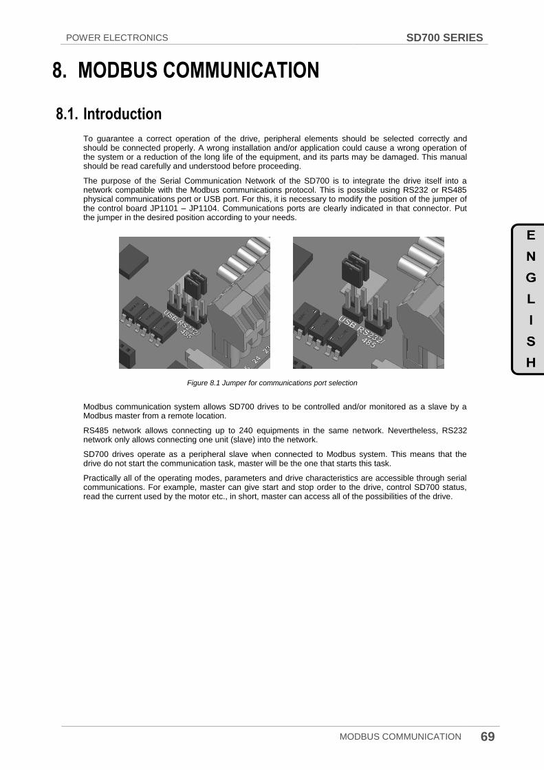
POWER ELECTRONICS SD700 SERIES
MODBUS COMMUNICATION 69
8. MODBUS COMMUNICATION
8.1. Introduction
To guarantee a correct operation of the drive, peripheral elements should be selected correctly and should be connected properly. A wrong installation and/or application could cause a wrong operation of the system or a reduction of the long life of the equipment, and its parts may be damaged. This manual should be read carefully and understood before proceeding.
The purpose of the Serial Communication Network of the SD700 is to integrate the drive itself into a network compatible with the Modbus communications protocol. This is possible using RS232 or RS485 physical communications port or USB port. For this, it is necessary to modify the position of the jumper of the control board JP1101 – JP1104. Communications ports are clearly indicated in that connector. Put the jumper in the desired position according to your needs.
Figure 8.1 Jumper for communications port selection
Modbus communication system allows SD700 drives to be controlled and/or monitored as a slave by a Modbus master from a remote location.
RS485 network allows connecting up to 240 equipments in the same network. Nevertheless, RS232 network only allows connecting one unit (slave) into the network.
SD700 drives operate as a peripheral slave when connected to Modbus system. This means that the drive do not start the communication task, master will be the one that starts this task.
Practically all of the operating modes, parameters and drive characteristics are accessible through serial communications. For example, master can give start and stop order to the drive, control SD700 status, read the current used by the motor etc., in short, master can access all of the possibilities of the drive.
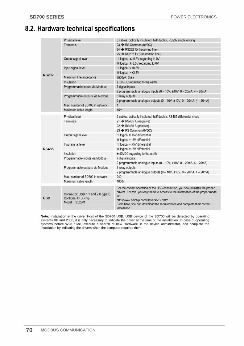
SD700 SERIES POWER ELECTRONICS
70 MODBUS COMMUNICATION
8.2. Hardware technical specifications
RS232
Physical level 3 cables, optically insulated, half duplex, RS232 single ending
Terminals 23 RS Common (0VDC)
24 RS232 Rx (receiving line)
25 RS232 Tx (transmitting line)
Output signal level '1' logical ≤ 6.5V regarding to 0V
'0' logical ≥ 6.5V regarding to 0V
Input signal level '1' logical < +0.8V
'0' logical > +2.4V
Maximum line impedance 2500pF, 3k
Insulation ± 50VDC regarding to the earth
Programmable inputs via Modbus 7 digital inputs
2 programmable analogue inputs (0 – 10V, ±10V, 0 – 20mA, 4 – 20mA)
Programmable outputs via Modbus 3 relay outputs
2 programmable analogue outputs (0 – 10V, ±10V, 0 – 20mA, 4 – 20mA)
Max. number of SD700 in network 1
Maximum cable length 15m
RS485
Physical level 2 cables, optically insulated, half duplex, RS485 differential mode
Terminals 21 RS485 A (negative)
22 RS485 B (positive)
23 RS Common (0VDC)
Output signal level '1' logical = +5V differential
'0' logical = -5V differential
Input signal level '1' logical = +5V differential
'0' logical = -5V differential
Insulation ± 50VDC regarding to the earth
Programmable inputs via Modbus 7 digital inputs
2 programmable analogue inputs (0 – 10V, ±10V, 0 – 20mA, 4 – 20mA)
Programmable outputs via Modbus 3 relay outputs
2 programmable analogue outputs (0 – 10V, ±10V, 0 – 20mA, 4 – 20mA)
Max. number of SD700 in network 240
Maximum cable length 1000m
USB Connector: USB 1.1 and 2.0 type B. Controller FTDI chip Model FT232BM
For the correct operation of the USB connection, you should install the proper drivers. For this, you only need to access to the information of the proper model in: http://www.ftdichip.com/Drivers/VCP.htm From here, you can download the required files and complete their correct installation.
Note: Installation in the driver Host of the SD700 USB, USB device of the SD700 will be detected by operating systems XP and 2000, it is only necessary to indicate the driver at the time of the installation. In case of operating systems before W98 / Me, execute a search of new Hardware in the device administrator, and complete the installation by indicating the drivers when the computer requires them.
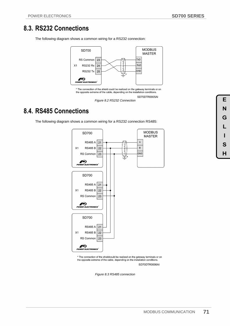
POWER ELECTRONICS SD700 SERIES
MODBUS COMMUNICATION 71
8.3. RS232 Connections
The following diagram shows a common wiring for a RS232 connection:
Figure 8.2 RS232 Connection
8.4. RS485 Connections
The following diagram shows a common wiring for a RS232 connection RS485:
Figure 8.3 RS485 connection

SD700 SERIES POWER ELECTRONICS
72 COMMISSIONING
9. COMMISSIONING
CAUTION
Only qualified personnel are allowed to commission the drive. Read and follow the safety instructions on the first pages of this manual. Neglecting the safety instructions can cause injury or
death.
Ensure that there is no voltage present in the input power terminals and no voltage can be connected to the drive inadvertently.
This chapter do not include all the tasks to be performed during commissioning, follow local and national regulations.
For a properly commissioning, we recommend checking the following steps:
Check the compatibility of the upstream protections (circuit breaker, fuses, etc...) that could cause an unexpected stop during the soft charge.
Assure that the line voltage is compatible with drive voltage range. On the contrary, the drive could be damaged.
Connect input, PE and output power wiring, and verify that they are correctly installed and fastened.
Check that the drive protective covers are mounted and doors are properly closed.
Check control, and analogue and digital signals cables, functions (STO). Potential free.
Check that the drive follows the remote and local speed commands.

POWER ELECTRONICS SD700 SERIES
COMMISSIONING 73
Verify that the display is turned on and set the drive control parameters (Follow the instruction delivered in Software and Programming manual).
Check line voltages displayed.
Start the drive without motor using the display‟s keyboard pushbutton “START”.
Check that the fans rotate smoothly and there is any obstacle reducing the cooling capacity.
Connect the motor and check its rotation direction.
Check that the drive follows the references of speed, current, etc.
Connect input power supply.
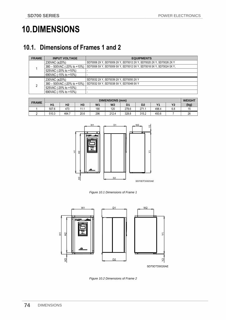
SD700 SERIES POWER ELECTRONICS
74 DIMENSIONS
10. DIMENSIONS
10.1. Dimensions of Frames 1 and 2
FRAME INPUT VOLTAGE EQUIPMENTS
1
230VAC (±20%) SD70006 2X Y, SD70009 2X Y, SD70012 2X Y, SD70020 2X Y, SD70026 2X Y
380 – 500VAC (-20% to +10%) SD70006 5X Y, SD70009 5X Y, SD70012 5X Y, SD70018 5X Y, SD70024 5X Y,
525VAC (-20% to +10%) -
690VAC (-15% to +10%) -
2
230VAC (±20%) SD70032 2X Y, SD70039 2X Y, SD70050 2X Y
380 – 500VAC (-20% to +10%) SD70032 5X Y, SD70038 5X Y, SD70048 5X Y
525VAC (-20% to +10%) -
690VAC (-15% to +10%) -
FRAME DIMENSIONS (mm) WEIGHT
(kg) H1 H2 H3 W1 W2 D1 D2 Y1 Y2
1 507.6 473 11.1 190 120 278.6 271.1 498.4 6.8 15
2 510.3 464.7 20.6 296 212.4 328.8 315.2 493.6 7 26
Figure 10.1 Dimensions of Frame 1
Figure 10.2 Dimensions of Frame 2

POWER ELECTRONICS SD700 SERIES
DIMENSIONS 75
10.2. Dimensions of Frames 3, 4 and 5
FRAME INPUT VOLTAGE EQUIPMENTS
3
230VAC (±20%) SD70064 2X Y, SD70075 2X Y, SD70090 2X Y, SD70115 2X Y
380 – 500VAC (-20% to +10%) SD70060 5X Y, SD70075 5X Y, SD70090 5X Y, SD70115 5X Y
525VAC (-20% to +10%) -
690VAC (-15% to +10%) SD70052 6X Y, SD70062 6X Y
4
230VAC (±20%) SD70150 2X Y, SD70170 2X Y
380 – 500VAC (-20% to +10%) SD70150 5X Y, SD70170 5X Y
525VAC (-20% to +10%) SD70100 7X Y, SD70120 7X Y, SD70145 7X Y
690VAC (-15% to +10%) SD70080 6X Y, SD70105 6X Y
5
230VAC (±20%) SD70210 2X Y, SD70250 2X Y, SD70275 2X Y
380 – 500VAC (-20% to +10%) SD70210 5X Y, SD70250 5X Y, SD70275 5X Y
525VAC (-20% to +10%) SD70180 7X Y, SD70205 7X Y
690VAC (-15% to +10%) SD70130 6X Y, SD70150 6X Y, SD70170 6X Y
FRAME DIMENSIONS (mm) WEIGHT
(kg) H1 H2 W1 W2 W3 D1 D2 Y1 Y2 Y3 Y4
3 853.5 838.5 300.5 200 140 358 - 827 15 - - 67.5
4 1245 1206 320 251 - 438.5 - 881 527.5 353.5 - 94
5 1712 1667 431 396 - 529 460 1403.5 1240.5 81.5 - 200
Figure 10.3 Dimensions of Frame 3 Figure 10.4 Dimensions of Frame 4
Figure 10.5 Dimensions of Frame 5

SD700 SERIES POWER ELECTRONICS
76 DIMENSIONS
10.3. Dimensions of Frames 6 and 7
FRAME INPUT VOLTAGE EQUIPMENTS
6
230VAC (±20%) SD70330 2X Y, SD70370 2X Y, SD70460 2X Y
380 – 500VAC (-20% to +10%) SD70330 5X Y, SD70370 5X Y, SD70460 5X Y, SD70330 5X 12 Y, SD70370 5X 12 Y, SD70460 5X 12 Y
525VAC (-20% to +10%) SD70270 7X Y, SD70295 7X Y, SD70340 7X Y, SD70270 7X 12 Y, SD70295 7X 12 Y, SD70340 7X 12 Y
690VAC (-15% to +10%) SD70210 6X Y, SD70260 6X Y, SD70320 6X Y, SD70210 6X 12 Y, SD70260 6X 12 Y, SD70320 6X 12 Y
7
230VAC (±20%) SD70580 2X Y, SD70650 2X Y, SD70720 2X Y
380 – 500VAC (-20% to +10%) SD70580 5X Y, SD70650 5X Y, SD70720 5X Y, SD70580 5X 18 Y, SD70650 5X 18 Y, SD70720 5X 18 Y
525VAC (-20% to +10%) SD70425 7X Y, SD70470 7X Y, SD70535 7X Y, SD70425 7X 18 Y, SD70470 7X 18 Y, SD70535 7X 18 Y
690VAC (-15% to +10%) SD70385 6X Y, SD70460 6X Y, SD70385 6X 18 Y, SD70460 6X 18 Y
FRAME DIMENSIONS (mm) WEIGHT
(kg) H1 H2 W1 W2 W3 D1 D2 Y1 Y2 Y3 Y4
6 1712 1667 786 747 - 529 460 1602 1208.5 230.5 81.5 335
7 1712 1667 1132 1097 - 529 460 1602 1208.5 230.5 81.5 479
Figure 10.6 Dimensions of Frame 6
Figure 10.7 Dimensions of Frame 7
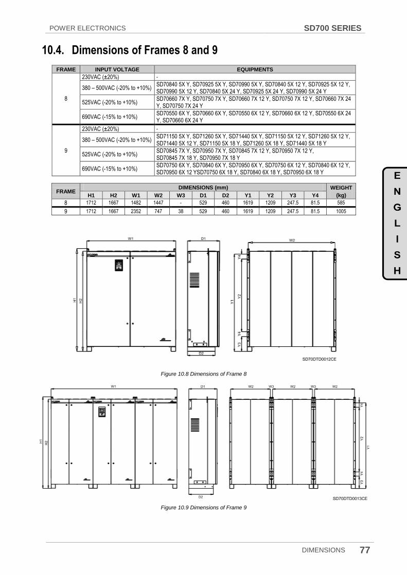
POWER ELECTRONICS SD700 SERIES
DIMENSIONS 77
10.4. Dimensions of Frames 8 and 9
FRAME INPUT VOLTAGE EQUIPMENTS
8
230VAC (±20%) -
380 – 500VAC (-20% to +10%) SD70840 5X Y, SD70925 5X Y, SD70990 5X Y, SD70840 5X 12 Y, SD70925 5X 12 Y, SD70990 5X 12 Y, SD70840 5X 24 Y, SD70925 5X 24 Y, SD70990 5X 24 Y
525VAC (-20% to +10%) SD70660 7X Y, SD70750 7X Y, SD70660 7X 12 Y, SD70750 7X 12 Y, SD70660 7X 24 Y, SD70750 7X 24 Y
690VAC (-15% to +10%) SD70550 6X Y, SD70660 6X Y, SD70550 6X 12 Y, SD70660 6X 12 Y, SD70550 6X 24 Y, SD70660 6X 24 Y
9
230VAC (±20%) -
380 – 500VAC (-20% to +10%) SD71150 5X Y, SD71260 5X Y, SD71440 5X Y, SD71150 5X 12 Y, SD71260 5X 12 Y, SD71440 5X 12 Y, SD71150 5X 18 Y, SD71260 5X 18 Y, SD71440 5X 18 Y
525VAC (-20% to +10%) SD70845 7X Y, SD70950 7X Y, SD70845 7X 12 Y, SD70950 7X 12 Y, SD70845 7X 18 Y, SD70950 7X 18 Y
690VAC (-15% to +10%) SD70750 6X Y, SD70840 6X Y, SD70950 6X Y, SD70750 6X 12 Y, SD70840 6X 12 Y, SD70950 6X 12 YSD70750 6X 18 Y, SD70840 6X 18 Y, SD70950 6X 18 Y
FRAME DIMENSIONS (mm) WEIGHT
(kg) H1 H2 W1 W2 W3 D1 D2 Y1 Y2 Y3 Y4
8 1712 1667 1482 1447 - 529 460 1619 1209 247.5 81.5 585
9 1712 1667 2352 747 38 529 460 1619 1209 247.5 81.5 1005
Figure 10.8 Dimensions of Frame 8
Figure 10.9 Dimensions of Frame 9

SD700 SERIES POWER ELECTRONICS
78 DIMENSIONS
10.5. Dimensions of Frames 10 and 11
FRAME INPUT VOLTAGE EQUIPMENTS
10
230VAC (±20%) -
380 – 500VAC (-20% to +10%) SD71580 5X Y, SD71800 5X Y, SD71580 5X 18 Y, SD71800 5X 18 Y
525VAC (-20% to +10%) SD71070 7X Y, SD71205 7X Y, SD71340 7X Y, SD71605 7X Y, SD71070 7X 18 Y, SD71205 7X 18 Y, SD71340 7X 18 Y, SD71605 7X 18 Y
690VAC (-15% to +10%) SD71140 6X Y, SD71270 6X Y, SD71420 6X Y, SD71140 6X 18 Y, SD71270 6X 18 Y, SD71420 6X 18 Y
11
230VAC (±20%) -
380 – 500VAC (-20% to +10%) SD72200 5X Y, SD72500 5X Y, SD72200 5X 12 Y, SD72500 5X 12 Y, SD72200 5X 18 Y, SD72500 5X 18 Y, SD72200 5X 24 Y, SD72500 5X 24 Y,
525VAC (-20% to +10%) SD72005 7X Y, SD72005 7X 12 Y, SD72005 7X 18 Y, SD72005 7X 24 Y
690VAC (-15% to +10%) SD71500 6X Y, SD71800 6X Y, SD71500 6X 12 Y, SD71800 6X 12 Y, SD71500 6X 18 Y, SD71800 6X 18 Y, SD71500 6X 24 Y, SD71800 6X 24 Y
FRAME DIMENSIONS (mm) WEIGHT
(kg) H1 H2 W1 W2 W3 D1 D2 Y1 Y2 Y3 Y4
10 1712 1667 3402 1097 38 529 460 1619 1209 247.5 81.5 1437
11 1712 1667 4452 1447 38 529 460 1619 1209 247.5 81.5 1755
Figure 10.10 Dimensions of Frame 10
Figure 10.11 Dimensions of Frame 11

POWER ELECTRONICS SD700 SERIES
MAINTENANCE 79
11. MAINTENANCE
SD700 drives consist of advanced semiconductor devices. Temperature, humidity, vibration and deteriorated components can reduce their efficiency. To avoid any possible irregularity we recommend making periodic inspections.
11.1. Warnings
Be sure to remove the input power while performing maintenance.
Be sure to perform maintenance after checking the DC Link capacitor has discharged. Check that the voltage between terminals +HVDC and -HVDC is below DC 30V. The bus capacitors in the drive main circuit can still be charged even after the power is turned off.
The correct output voltage of the drive can only be measured by using an RMS voltage meter. Others voltage meters, including digital voltage meters, are likely to display incorrect values caused by the high frequency PWM output voltage of the drive.
11.2. Routine Inspection
Be sure to check the following points before handling the drive:
Installation site conditions.
Drive cooling system conditions.
Excessive vibrations or noise in the motor.
Excessive overheating.
Normal output current value on the monitor.
Insp
ecti
on
site
Inspection element
Inspection
Period
Inspection method Criterion Instrument of Measurement
Mo
nth
ly
1 ye
ar
2 ye
ars
All
Ambient conditions
Are there dust particles? Are the ambient temperature and the humidity within specification?
o Visual check
Temperature: -30 to +50 ( or 40ºC) Humidity: below 95% non-condensing.
Thermometer, Hygrometer, Recorder.
Module Are there any abnormal noises or oscillations?
o Visual and audible. There are no anomalies.
Input power Is the input power to the main circuit correct?
o Measure the voltage between terminals L1, L2, L3 and PE.
Digital multimeter. Tester.
Power connections
Are the Power terminals correctly fastened?
o Measure the temperature and torque of the power connections
Fasten the bolts again one week after its start-up. Check that the temperature is homogeneous and below 70ºC
Infrared thermometer , Torque key
Mai
n c
ircu
it
Conductor/ Cable
Is the conductor corroded? Is the sheathing of the cable damaged?
o
o
Visual check. No anomaly.
Terminal Is any damage visible? o Visual check. No anomaly.
IGBT's module Diodes module and Rectifier
Check the resistance value between each one of the terminals
o
Disconnect the cables of the inverter and measure the resistance value between: L1, L2, L3, VDC+, VDC- and U, V, W VDC+, VDC-
with a tester > 10k
Digital multimeter. Analogue tester.
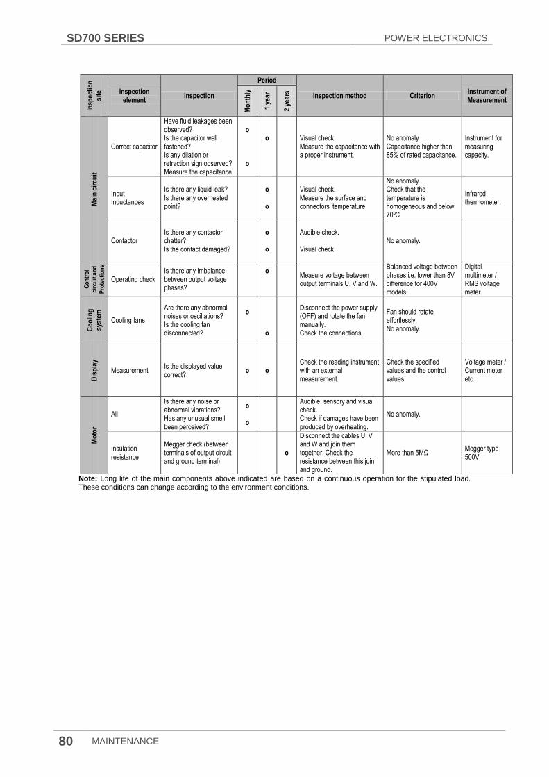
SD700 SERIES POWER ELECTRONICS
80 MAINTENANCE
Note: Long life of the main components above indicated are based on a continuous operation for the stipulated load. These conditions can change according to the environment conditions.
Insp
ecti
on
site
Inspection element
Inspection
Period
Inspection method Criterion Instrument of Measurement
Mo
nth
ly
1 ye
ar
2 ye
ars
Mai
n c
ircu
it
Correct capacitor
Have fluid leakages been observed? Is the capacitor well fastened? Is any dilation or retraction sign observed? Measure the capacitance
o
o
o
Visual check. Measure the capacitance with a proper instrument.
No anomaly Capacitance higher than 85% of rated capacitance.
Instrument for measuring capacity.
Input Inductances
Is there any liquid leak? Is there any overheated point?
o
o
Visual check. Measure the surface and connectors’ temperature.
No anomaly. Check that the temperature is homogeneous and below 70ºC
Infrared thermometer.
Contactor Is there any contactor chatter? Is the contact damaged?
o
o
Audible check. Visual check.
No anomaly.
Co
ntr
ol
circ
uit
an
d
Pro
tect
ion
s
Operating check Is there any imbalance between output voltage phases?
o
Measure voltage between output terminals U, V and W.
Balanced voltage between phases i.e. lower than 8V difference for 400V models.
Digital multimeter / RMS voltage meter.
Co
olin
g
syst
em
Cooling fans
Are there any abnormal noises or oscillations? Is the cooling fan disconnected?
o
o
Disconnect the power supply (OFF) and rotate the fan manually. Check the connections.
Fan should rotate effortlessly. No anomaly.
Dis
pla
y
Measurement Is the displayed value correct?
o o Check the reading instrument with an external measurement.
Check the specified values and the control values.
Voltage meter / Current meter etc.
Mo
tor
All
Is there any noise or abnormal vibrations? Has any unusual smell been perceived?
o
o
Audible, sensory and visual check. Check if damages have been produced by overheating.
No anomaly.
Insulation resistance
Megger check (between terminals of output circuit and ground terminal)
o
Disconnect the cables U, V and W and join them together. Check the resistance between this join and ground.
More than 5MΩ Megger type 500V
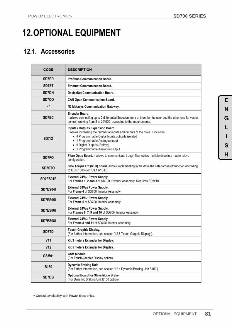
POWER ELECTRONICS SD700 SERIES
OPTIONAL EQUIPMENT 81
12. OPTIONAL EQUIPMENT
12.1. Accessories
CODE DESCRIPTION
SD7PD Profibus Communication Board.
SD7ET Ethernet Communication Board.
SD7DN DeviceNet Communication Board.
SD7CO CAN Open Communication Board.
- * N2 Metasys Communication Gateway.
SD7EC Encoder Board. It allows connecting up to 2 differential Encoders (one of them for the user and the other one for vector control) working from 5 to 24VDC, according to the requirements.
SD7IO
Inputs / Outputs Expansion Board. It allows increasing the number of inputs and outputs of the drive. It includes:
4 Programmable Digital Inputs optically isolated
1 Programmable Analogue Input
5 Digital Outputs (Relays)
1 Programmable Analogue Output
SD7FO Fibre Optic Board. It allows to communicate trough fiber optics multiple drive in a master slave configuration.
SD7STO Safe Torque Off (STO) board. Allows implementing in the drive the safe torque off function according to IEC 61800-5-2 (SIL1 or SIL3).
SD7ES01E External 24VDC Power Supply. For Frames 1, 2 and 3 of SD700. Exterior Assembly. Requires SD7EBI
SD7ES04I External 24VDC Power Supply. For Frame 4 of SD700. Interior Assembly.
SD7ES05I External 24VDC Power Supply. For Frame 5 of SD700. Interior Assembly.
SD7ES06I External 24VDC Power Supply. For Frames 6, 7, 9 and 10 of SD700. Interior Assembly.
SD7ES08I External 24VDC Power Supply. For Frame 8 and 11 of SD700. Interior Assembly.
SD7TD Touch-Graphic Display. (For further information, see section ’12.5 Touch-Graphic Display’).
V11 Kit 3 meters Extender for Display.
V12 Kit 5 meters Extender for Display.
GSM01 GSM Module. (For Touch-Graphic Display option).
B150 Dynamic Braking Unit. (For further information, see section ‘12.4 Dynamic Braking Unit B150’).
SD7DB Optional Board for Slave Mode Brake. (For Dynamic Braking Unit B150 option).
Consult availability with Power Electronics.
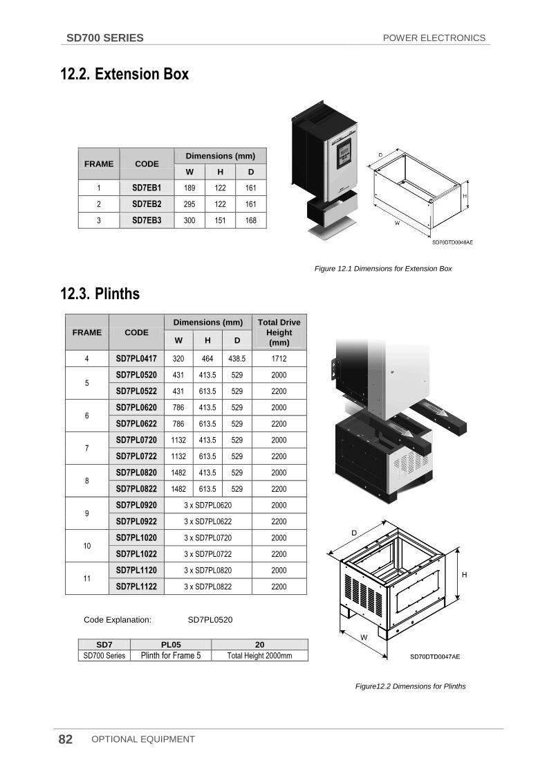
SD700 SERIES POWER ELECTRONICS
82 OPTIONAL EQUIPMENT
12.2. Extension Box
FRAME CODE Dimensions (mm)
W H D
1 SD7EB1 189 122 161
2 SD7EB2 295 122 161
3 SD7EB3 300 151 168
Figure 12.1 Dimensions for Extension Box
12.3. Plinths
FRAME CODE
Dimensions (mm) Total Drive
Height
(mm) W H D
4 SD7PL0417 320 464 438.5 1712
5 SD7PL0520 431 413.5 529 2000
SD7PL0522 431 613.5 529 2200
6 SD7PL0620 786 413.5 529 2000
SD7PL0622 786 613.5 529 2200
7 SD7PL0720 1132 413.5 529 2000
SD7PL0722 1132 613.5 529 2200
8 SD7PL0820 1482 413.5 529 2000
SD7PL0822 1482 613.5 529 2200
9 SD7PL0920 3 x SD7PL0620 2000
SD7PL0922 3 x SD7PL0622 2200
10 SD7PL1020 3 x SD7PL0720 2000
SD7PL1022 3 x SD7PL0722 2200
11 SD7PL1120 3 x SD7PL0820 2000
SD7PL1122 3 x SD7PL0822 2200
Code Explanation: SD7PL0520
SD7 PL05 20
SD700 Series Plinth for Frame 5 Total Height 2000mm
Figure12.2 Dimensions for Plinths

POWER ELECTRONICS SD700 SERIES
OPTIONAL EQUIPMENT 83
12.4. Dynamic Braking Unit B150
The Dynamic brake permits to control the regenerated energy for series SD700, SD700KOMPAKT and SD700FL. B150 dynamic brake activates an IGBT to discharge the DC bus over external resistors when the DC voltage overpasses a pre-set value. This activation signal could also be delivered by the drive acquiring an optional Master- Slave mode braking board.
The B150, with reduced dimensions and high reliability, is the main power-switching device of such a dynamic braking systems.
Figure 12.3 Dynamic Braking Unit. Dimensions [mm]
REFERENCE VOLTAGE
CURRENT (A) MINIMUM
RESISTANCE
RATING (Ω)
DIMENSIONS (MM)
WEIGHT MAXIMUM CONTINUOUS W D H
B150.2 230Vac 300A 150A 2.4Ω
177 221 352 7 kg B150 400Vac, 500Vac 300A 150A 2.4Ω
B150.6 690Vac 200A 100A 5.75Ω
12.4.1. Optional Board for Slave Mode Brake
There is the possibility for the drive to control the activation of the dynamic braking module B150. In this way, the optional board SD7DB must be used to allowi the drive to control the dynamic braking unit B150 that will operate as slave unit of the drive. This optional board is not required in case of the unit B150 operates in master mode.
Figure 12.4 Optional Board for Slave Mode Brake
(SD7DB)

SD700 SERIES POWER ELECTRONICS
84 OPTIONAL EQUIPMENT
12.5. Touch-Graphic Display
The Touch-Graphic Display provides a much more intuitive data presentation, an easy navigation through the control parameters and allows saving thousands of customized configurations defined by the user. Some of the outstanding characteristics of the graphic display are:
TFT-LCD Touch screen of 3,5 inches and 240x320 pixels
Customized visualization by the user
GSM and GPRS communication (SMS Service)
System help built-in
Fault Register (Logs)
Language selection
4 Gbytes Micro SD for data history storage.
Built in Quad band GSM Modem for sending SMS with Consultations or Notifications (Events, Alarms...)
Dual Ethernet Connection –LAN RJ45 and USB connection.
Possibility of external or battery 5Vdc power supply.
The Touch-Graphic display for the SD700 is a removable display unit for its remote installation, as the following figure shows:
Figure 12.5 Touch-Graphic Display Unit
There are three indicator leds integrated on the display that supply information about the drive operational status. In addition, there are a LCD screen of 3.5” and two control keys to Start / Stop the drive.
12.6. Communication boards
SD700 family is compatible with the most commonly used communication protocols (Profibus-DP, DeviceNet, Modbus TCP, Ethernet IP, N2 Metasys, CAN Open…), thanks to its optional boards.
Figure 12.6 Example of Profibus optional board

POWER ELECTRONICS SD700 SERIES
CE MARKING 85
13. CE MARKING
The CE Marking is a system to identify equipment that complies with the relevant directives (EMC directive). CE marking guarantees the free movement of the product within the EEA. CE marking shows that the product complies with technical safety, compatibility issues and conformity assessment.
13.1. EMC Directive
The EMC Directive defines the requirements for immunity and emissions of electrical equipment used within the European Union. SD700 Series drives are in accordance with the directive IEC 61800-3:2004 about adjustable speed electrical power drive systems.
13.2. Low Voltage Directive
The low voltage directive defines the security requirements of low voltage electrical equipment in order to circulate freely within the European Economic Area. SD700 Series drives are in accordance with the directive IEC 61800-5-1:2007 about adjustable speed electrical power drive systems.

SD700 SERIES POWER ELECTRONICS
86

DECLARATION OF CONFORMITY CE
The Company: Name: POWER ELECTRONICS ESPAÑA, S.L. Address: C/ Leonardo Da Vinci, 24-26, 46980 Paterna (Valencia) Telephone: +34 96 136 65 57 Fax: +34 96 131 82 01 Declares under its own responsibility, that the product:
Variable Speed Drive for A.C. motors
Brand: Power Electronics Model name: SD700 Series
Is in conformity with the following European Directives:
References Title
2006/95/CE Electrical Material intended to be used with certain limits of voltage
2004/108/CE Electromagnetic Compatibility
*2006/42/CE Machinery directive
*Models with optional STO card installed References of the harmonized technical norms applied under the Low Voltage Directive:
References Title
EN 61800-5-1:2007 Adjustable speed electrical power drive systems - Part 5-1: Safety requirements - Electrical, thermal and energy (IEC 61800-5-1:2007);
References of the harmonized technical norms applied under the Electromagnetic Compatibility Directive:
References Title
IEC 61800-3:2004 Adjustable speed electrical power drive systems. Part 3: EMC requirements and specific test methods.
References of the harmonized technical norms applied under the Machinery Directive:
References Title
IEC 61800-5-2:2007 Adjustable speed electrical power drive systems. Part 5-2: Safety requirements - Functional
Paterna, October 5
th 2012
David Salvo Executive Director
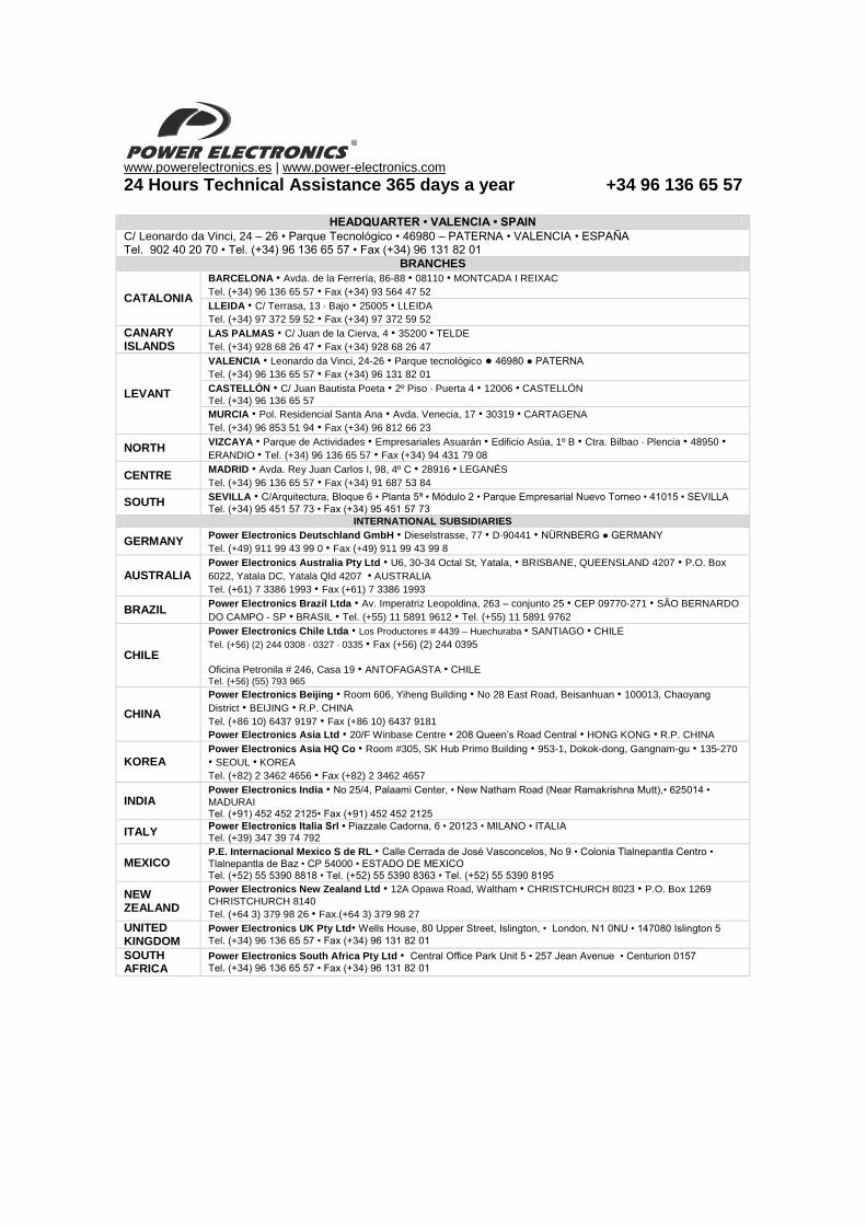
www.powerelectronics.es | www.power-electronics.com
24 Hours Technical Assistance 365 days a year +34 96 136 65 57
HEADQUARTER • VALENCIA • SPAIN
C/ Leonardo da Vinci, 24 – 26 • Parque Tecnológico • 46980 – PATERNA • VALENCIA • ESPAÑA Tel. 902 40 20 70 • Tel. (+34) 96 136 65 57 • Fax (+34) 96 131 82 01
BRANCHES
CATALONIA
BARCELONA • Avda. de la Ferrería, 86-88 • 08110 • MONTCADA I REIXAC
Tel. (+34) 96 136 65 57 • Fax (+34) 93 564 47 52
LLEIDA • C/ Terrasa, 13 · Bajo • 25005 • LLEIDA
Tel. (+34) 97 372 59 52 • Fax (+34) 97 372 59 52
CANARY ISLANDS
LAS PALMAS • C/ Juan de la Cierva, 4 • 35200 • TELDE
Tel. (+34) 928 68 26 47 • Fax (+34) 928 68 26 47
LEVANT
VALENCIA • Leonardo da Vinci, 24-26 • Parque tecnológico 46980 PATERNA
Tel. (+34) 96 136 65 57 • Fax (+34) 96 131 82 01
CASTELLÓN • C/ Juan Bautista Poeta • 2º Piso · Puerta 4 • 12006 • CASTELLÓN
Tel. (+34) 96 136 65 57
MURCIA • Pol. Residencial Santa Ana • Avda. Venecia, 17 • 30319 • CARTAGENA
Tel. (+34) 96 853 51 94 • Fax (+34) 96 812 66 23
NORTH VIZCAYA • Parque de Actividades • Empresariales Asuarán • Edificio Asúa, 1º B • Ctra. Bilbao · Plencia • 48950 • ERANDIO • Tel. (+34) 96 136 65 57 • Fax (+34) 94 431 79 08
CENTRE MADRID • Avda. Rey Juan Carlos I, 98, 4º C • 28916 • LEGANÉS
Tel. (+34) 96 136 65 57 • Fax (+34) 91 687 53 84
SOUTH SEVILLA • C/Arquitectura, Bloque 6 • Planta 5ª • Módulo 2 • Parque Empresarial Nuevo Torneo • 41015 • SEVILLA
Tel. (+34) 95 451 57 73 • Fax (+34) 95 451 57 73
INTERNATIONAL SUBSIDIARIES
GERMANY Power Electronics Deutschland GmbH • Dieselstrasse, 77 • D·90441 • NÜRNBERG GERMANY
Tel. (+49) 911 99 43 99 0 • Fax (+49) 911 99 43 99 8
AUSTRALIA Power Electronics Australia Pty Ltd • U6, 30-34 Octal St, Yatala, • BRISBANE, QUEENSLAND 4207 • P.O. Box
6022, Yatala DC, Yatala Qld 4207 • AUSTRALIA
Tel. (+61) 7 3386 1993 • Fax (+61) 7 3386 1993
BRAZIL Power Electronics Brazil Ltda • Av. Imperatriz Leopoldina, 263 – conjunto 25 • CEP 09770-271 • SÃO BERNARDO
DO CAMPO - SP • BRASIL • Tel. (+55) 11 5891 9612 • Tel. (+55) 11 5891 9762
CHILE
Power Electronics Chile Ltda • Los Productores # 4439 – Huechuraba • SANTIAGO • CHILE
Tel. (+56) (2) 244 0308 · 0327 · 0335 • Fax (+56) (2) 244 0395
Oficina Petronila # 246, Casa 19 • ANTOFAGASTA • CHILE Tel. (+56) (55) 793 965
CHINA
Power Electronics Beijing • Room 606, Yiheng Building • No 28 East Road, Beisanhuan • 100013, Chaoyang
District • BEIJING • R.P. CHINA
Tel. (+86 10) 6437 9197 • Fax (+86 10) 6437 9181
Power Electronics Asia Ltd • 20/F Winbase Centre • 208 Queen‟s Road Central • HONG KONG • R.P. CHINA
KOREA Power Electronics Asia HQ Co • Room #305, SK Hub Primo Building • 953-1, Dokok-dong, Gangnam-gu • 135-270
• SEOUL • KOREA
Tel. (+82) 2 3462 4656 • Fax (+82) 2 3462 4657
INDIA Power Electronics India • No 25/4, Palaami Center, • New Natham Road (Near Ramakrishna Mutt),• 625014 •
MADURAI Tel. (+91) 452 452 2125• Fax (+91) 452 452 2125
ITALY Power Electronics Italia Srl • Piazzale Cadorna, 6 • 20123 • MILANO • ITALIA Tel. (+39) 347 39 74 792
MEXICO P.E. Internacional Mexico S de RL • Calle Cerrada de José Vasconcelos, No 9 • Colonia Tlalnepantla Centro •
Tlalnepantla de Baz • CP 54000 • ESTADO DE MEXICO Tel. (+52) 55 5390 8818 • Tel. (+52) 55 5390 8363 • Tel. (+52) 55 5390 8195
NEW ZEALAND
Power Electronics New Zealand Ltd • 12A Opawa Road, Waltham • CHRISTCHURCH 8023 • P.O. Box 1269
CHRISTCHURCH 8140
Tel. (+64 3) 379 98 26 • Fax.(+64 3) 379 98 27
UNITED KINGDOM
Power Electronics UK Pty Ltd• Wells House, 80 Upper Street, Islington, • London, N1 0NU • 147080 Islington 5
Tel. (+34) 96 136 65 57 • Fax (+34) 96 131 82 01
SOUTH AFRICA
Power Electronics South Africa Pty Ltd • Central Office Park Unit 5 • 257 Jean Avenue • Centurion 0157
Tel. (+34) 96 136 65 57 • Fax (+34) 96 131 82 01

www.power-electronics.com