Embed Size (px)
Citation preview
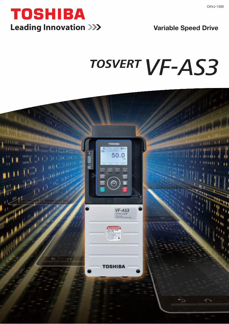
CKVJ-1300
Variable Speed Drive
2
Contents
Evolution to IoT-Ready drive. P3
Ideal for various applications. P5
All-in-One. Improvement in Usability. P7
Basic functions P9
Standard specifications P10
External dimensions P15
Standard connection diagrams P17
Terminal functions P18
For drive users P19
Peripheral devices P23
Insert type options P24
Totally enclosed box type for IP55 P34
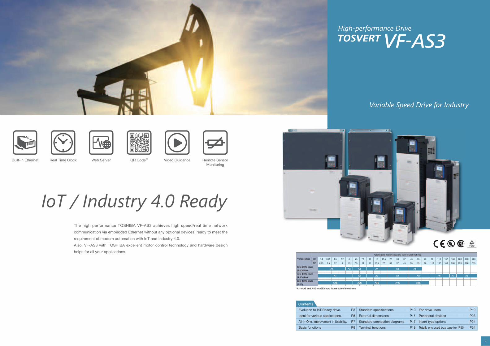
The high performance TOSHIBA VF-AS3 achieves high speed/real time network
communication via embedded Ethernet without any optional devices, ready to meet the
requirement of modern automation with IoT and Industry 4.0.
Also, VF-AS3 with TOSHIBA excellent motor control technology and hardware design
helps for all your applications.
IoT / Industry 4.0 Ready
Variable Speed Drive for Industry
Built-in Ethernet Real Time Clock Web Server QR Code ® Video Guidance Remote Sensor
Monitoring
High-performance Drive
Voltage class
Applicable motor capacity (kW) : Multi ratings
HD 0.4 0.75 1.5 2.2 4 5.5 7.5 11 15 18.5 22 30 37 45 55 75 90 110 132 160 200 220 280
ND 0.75 1.5 2.2 4 5.5 7.5 11 15 18.5 22 30 37 45 55 75 90 110 132 160 200 220 280 315
3ph-240V class
(IP20/IP00)
3ph-480V class
(IP20/IP00)
3ph-480V class
(IP55)
*A1 to A8 and A1E to A5E show frame size of the drives
A1 A2 A3 A4 A5 A6
A1 A2 A3 A4 A5 A6 A7 A8
A1E A2E A3E A4E A5E
3
Built-in Dual Ethernet Port
The VF-AS3 has an embedded Ethernet dual port adaptor that can
be used in the following Modbus TCP. The adaptor provides a set of
services at the Ethernet and TCP/IP level.
The dual Ethernet port adaptor offers an embedded Web server
which offers comfortable displaying and commissioning functions
directly from a standard web browser.
The VF-AS3 supports the following Automatic IP address assignment
via BOOTP and DHCP and Diagnostics and configuration via
integrated Web server.
Remote Sensor Monitoring
The sensor which is equipped in the machine and equipment, can be
connected with VF-AS3 and the status can be monitored by network
communication.
Evolution toIoT-Ready drive. The VF-AS3 is an IoT-Ready variable speed drive.
Using Internet, the VF-AS3 provides various
solutions to you.
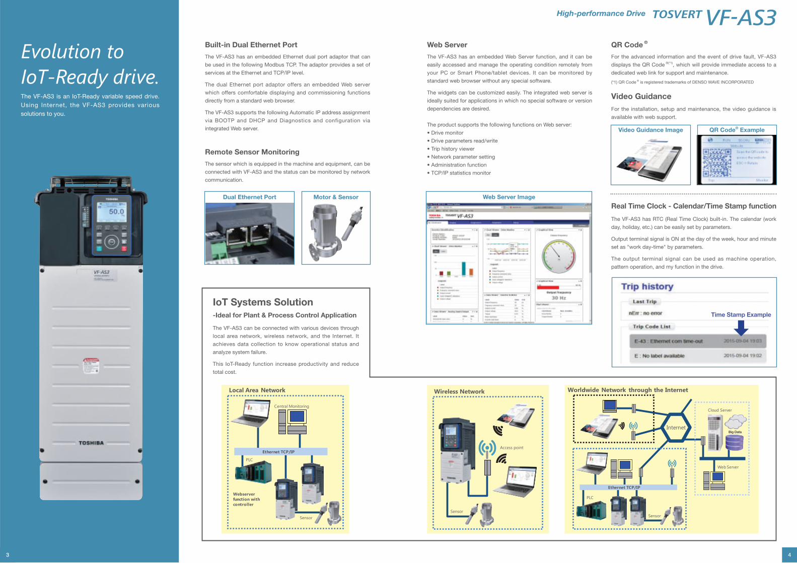
IoT Systems Solution
-Ideal for Plant & Process Control Application
The VF-AS3 can be connected with various devices through
local area network, wireless network, and the Internet. It
achieves data collection to know operational status and
analyze system failure.
This IoT-Ready function increase productivity and reduce
total cost.
Webserver function with controller
PLC
Sensor
Ethernet TCP/IP
Local Area Network
Central Monitoring
Dual Ethernet Port Motor & Sensor
4
Web Server
The VF-AS3 has an embedded Web Server function, and it can be
easily accessed and manage the operating condition remotely from
your PC or Smart Phone/tablet devices. It can be monitored by
standard web browser without any special software.
The widgets can be customized easily. The integrated web server is
ideally suited for applications in which no special software or version
dependencies are desired.
The product supports the following functions on Web server:
QR Code ®
For the advanced information and the event of drive fault, VF-AS3
displays the QR Code ®(*1), which will provide immediate access to a
dedicated web link for support and maintenance.
(*1) QR Code ®
Sensor
Access point
Wireless Network
Internet
Ethernet TCP/IP
Sensor
Cloud Server
Web Server
PLC
Worldwide Network through the Internet
Big Data
High-performance Drive
Real Time Clock - Calendar/Time Stamp function
The VF-AS3 has RTC (Real Time Clock) built-in. The calendar (work
day, holiday, etc.) can be easily set by parameters.
set as "work day-time" by parameters.
The output terminal signal can be used as machine operation,
pattern operation, and my function in the drive.
Web Server Image
Time Stamp Example
Video Guidance
For the installation, setup and maintenance, the video guidance is
available with web support.
QR Code® ExampleVideo Guidance Image
5 6
Ideal for various applications.The VF-AS3 has various functions dedicated to various applications.
The VF-AS3 will be the ideal choice for a wide variety of uses.
For Oil & Gas / Mining IndustryJack pumps / Compressor / Conveyor / Crushers / Compressor
For Water & Wastewater IndustryFan / Pump / Centrifuges
For Conveyor / Crane IndustryTransportation machine / Conveyor / Crushers / Compressor
For Chemical / Pharmaceutical IndustryPumps / Mixers / Compressor / Centrifuges / Fans
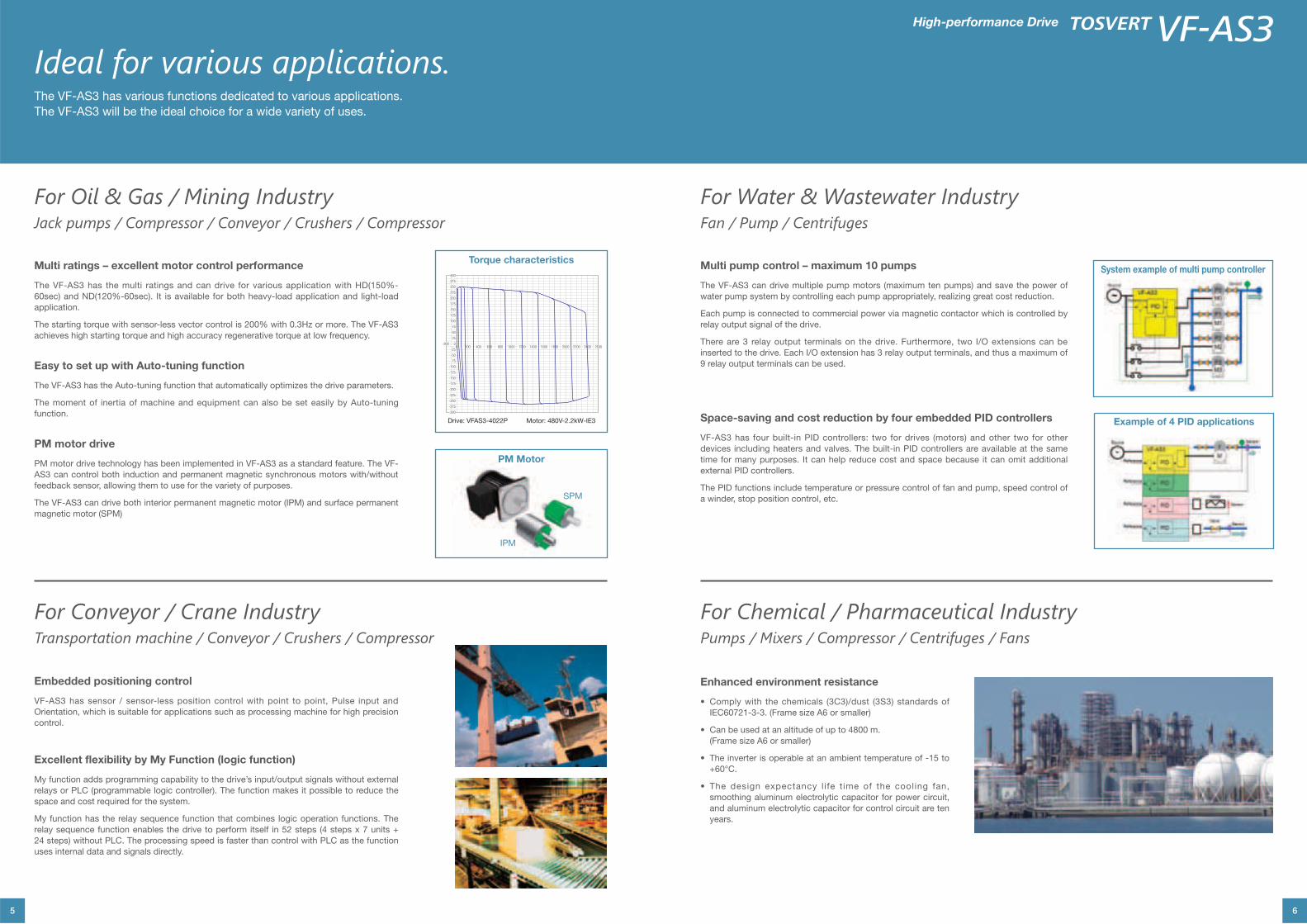
Multi ratings – excellent motor control performance
The VF-AS3 has the multi ratings and can drive for various application with HD(150%-
60sec) and ND(120%-60sec). It is available for both heavy-load application and light-load
application.
The starting torque with sensor-less vector control is 200% with 0.3Hz or more. The VF-AS3
achieves high starting torque and high accuracy regenerative torque at low frequency.
Multi pump control – maximum 10 pumps
The VF-AS3 can drive multiple pump motors (maximum ten pumps) and save the power of
water pump system by controlling each pump appropriately, realizing great cost reduction.
Each pump is connected to commercial power via magnetic contactor which is controlled by
relay output signal of the drive.
There are 3 relay output terminals on the drive. Furthermore, two I/O extensions can be
inserted to the drive. Each I/O extension has 3 relay output terminals, and thus a maximum of
9 relay output terminals can be used.
Space-saving and cost reduction by four embedded PID controllers
VF-AS3 has four built-in PID controllers: two for drives (motors) and other two for other
devices including heaters and valves. The built-in PID controllers are available at the same
time for many purposes. It can help reduce cost and space because it can omit additional
external PID controllers.
The PID functions include temperature or pressure control of fan and pump, speed control of
a winder, stop position control, etc.
Embedded positioning control
VF-AS3 has sensor / sensor-less position control with point to point, Pulse input and
Orientation, which is suitable for applications such as processing machine for high precision
control.
Enhanced environment resistance
(Frame size A6 or smaller)
smoothing aluminum electrolytic capacitor for power circuit,
and aluminum electrolytic capacitor for control circuit are ten
years.
Excellent flexibility by My Function (logic function)
My function adds programming capability to the drive’s input/output signals without external
space and cost required for the system.
My function has the relay sequence function that combines logic operation functions. The
uses internal data and signals directly.
Easy to set up with Auto-tuning function
The VF-AS3 has the Auto-tuning function that automatically optimizes the drive parameters.
The moment of inertia of machine and equipment can also be set easily by Auto-tuning
function.
PM motor drive
PM motor drive technology has been implemented in VF-AS3 as a standard feature. The VF-
AS3 can control both induction and permanent magnetic synchronous motors with/without
The VF-AS3 can drive both interior permanent magnetic motor (IPM) and surface permanent
magnetic motor (SPM)
High-performance Drive
300300
275275
250250
225225
200200
175175
150150
125125
100100
7575
5050
2525
0000 200200 400400 600600 800800 10001000 12001200 14001400 16001600 18001800 20002000 22002200 24002400 26002600
-200-200
-25-25
-50-50
-75-75
-100-100
-125-125
-150-150
-175-175
-200-200
-225-225
-250-250
-275-275
-300-300
Torque characteristics
PM Motor
SPM
IPM
System example of multi pump controller
Example of 4 PID applications
7 8
High-performance Drive
All-in-One. Improvement in Usability.The VF-AS3 allows various functions without external options.
The VF-AS3 realizes improvement in usability and cost reduction.
Not necessary to prepare optional devices separately.
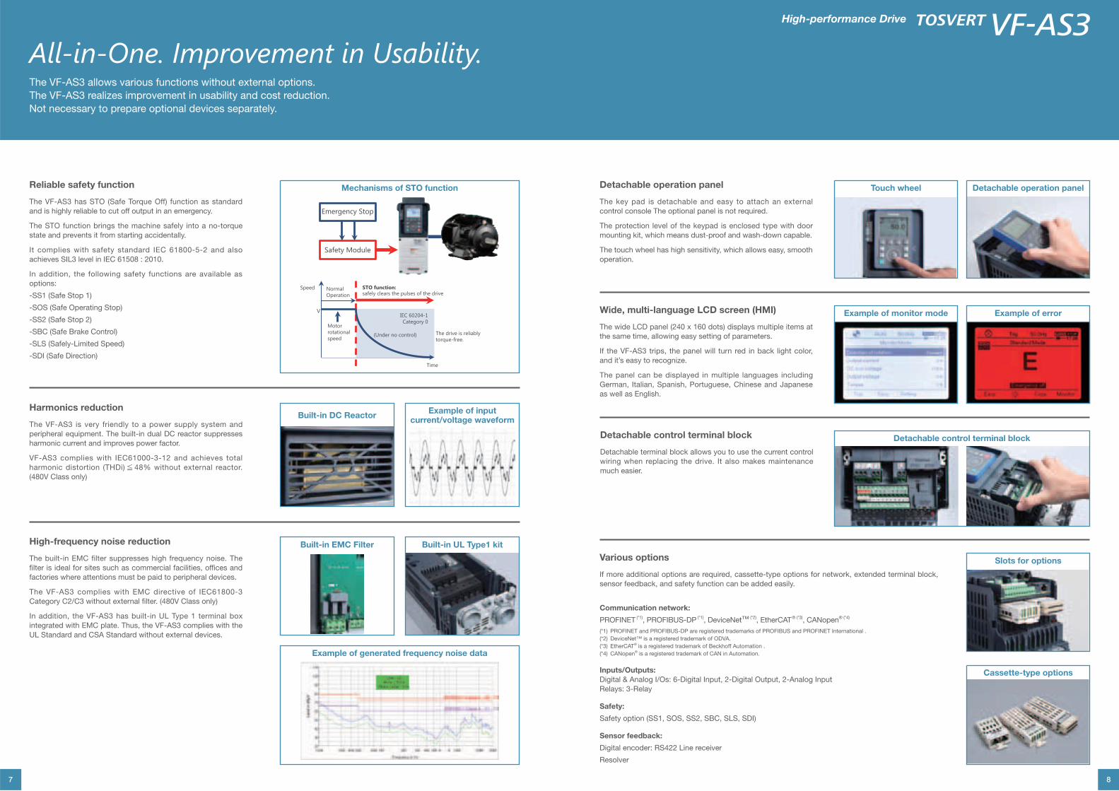
Reliable safety function
The VF-AS3 has STO (Safe Torque Off) function as standard
and is highly reliable to cut off output in an emergency.
The STO function brings the machine safely into a no-torque
state and prevents it from starting accidentally.
In addition, the following safety functions are available as
options:
-SS1 (Safe Stop 1)
-SOS (Safe Operating Stop)
-SS2 (Safe Stop 2)
-SLS (Safely-Limited Speed)
-SDI (Safe Direction)
Emergency Stop
Safety Module
NormalOperation
STO function:safely clears the pulses of the drive
Time
Speed
(Under no control)
Motor rotational speed
IEC 60204-1Category 0
The drive is reliably torque-free.
Mechanisms of STO function
Harmonics reduction
The VF-AS3 is very friendly to a power supply system and
harmonic current and improves power factor.
harmonic distortion (THDi)≦
Built-in DC ReactorExample of input
current/voltage waveform
High-frequency noise reduction
filter is ideal for sites such as commercial facilities, offices and
factories where attentions must be paid to peripheral devices.
In addition, the VF-AS3 has built-in UL Type 1 terminal box
Example of generated frequency noise data
Built-in EMC Filter Built-in UL Type1 kit
Various options
Communication network:
PROFINET (*1), PROFIBUS-DP (*1), DeviceNet™ (*2) ® (*3)
®
®
Inputs/Outputs:
Digital & Analog I/Os: 6-Digital Input, 2-Digital Output, 2-Analog Input
Relays: 3-Relay
Safety:
Sensor feedback:
Resolver
Slots for options
Cassette-type options
Detachable operation panel
control console The optional panel is not required.
The touch wheel has high sensitivity, which allows easy, smooth
operation.
Touch wheel Detachable operation panel
Wide, multi-language LCD screen (HMI)
the same time, allowing easy setting of parameters.
and it’s easy to recognize.
The panel can be displayed in multiple languages including
as well as English.
Example of monitor mode Example of error
Detachable control terminal block
much easier.
Detachable control terminal block
9
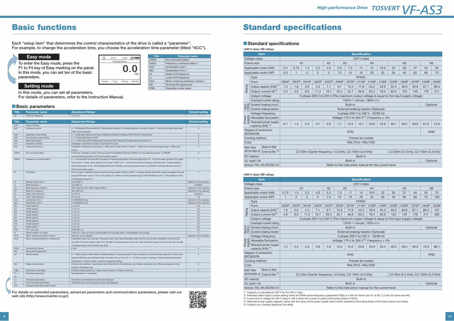
Basic functions
Each “setup item” that determines the control characteristics of the drive is called a “parameter”.For example, to change the acceleration time, you choose the acceleration time parameter (titled “ACC”).
Easy mode
To enter the Easy mode, press theF1 to F4 key of Easy marking on the panel. In this mode, you can set ten of the basic parameters.
Setting mode
In this mode, you can set all parameters.For details of parameters, refer to the Instruction Manual.
■Basic parametersTitle Parameter name Adjustment Range Default setting
FC Panel run frequency LL-UL Hz -
Title Parameter name Adjustment Range Default setting
AUH History function - -
AUF Guidance function
6:PM motor parameter
0
AUA Application easy setting 0
AUE Eco-standby power setting 0
AUL Multi-rating select 0
AU1 Automatic Acc/Dec 0
Torque boost macro
tuning
0
CMOd Run command select 0
FMOd Frequency command select 1 1
Pt V/f Pattern 0
vb Manual torque boost 1 0.00-30.00 % Depends on the capacity
vL Base frequency 1 15.0-590 Hz 50.0/60.0
vLv Base frequency voltage 1 Depends on the capacity
FH Maximum frequency 30.0-590.0 Hz Depends on the capacity
UL Upper limit frequency 0.0-FH Hz 50.0/60.0
LL Lower limit frequency 0.0-UL Hz 0.0
ACC Acceleration time 1 0.0-6000(600.0) sec Depends on the capacity
dEC Deceleration time 1 0.0-6000(600.0) sec Depends on the capacity
Sr0 Preset speed 0 LL-UL Hz 0.0
Sr1 Preset speed 1 LL-UL Hz 0.0
LL-UL Hz 0.0
Sr3 Preset speed 3 LL-UL Hz 0.0
Sr4 Preset speed 4 LL-UL Hz 0.0
Sr5 Preset speed 5 LL-UL Hz 0.0
Sr6 Preset speed 6 LL-UL Hz 0.0
LL-UL Hz 0.0
FPId PID 1 set value 0.0
Fr Panel Fwd/Rev run select 0
tHrA Motor overload protection current 1 Depends on the capacity Depends on the capacity
OLM Motor overload protection characteristic 0
FMSL Terminal FM function 0
FM Terminal FM adjustment - -
tyP Default setting
initialization) 14:Clear number of external equipment stating
0
SEt Region setting check
5:Mainly China(read only)
0
PSEL Parameter mode select 0
F1--~F9--
Extended parameters Set parameters in more detail -
A--- Advanced parameters Parameters with dedicated function are displayed -
C--- Communication parameters Parameters with communication function are displayed -
GrU Changed parameters search & edit - -
For details on extended parameters, advanced parameters and communication parameters, please visit our web site (http://www.inverter.co.jp/)
Title Parameter name
CMOd Run command select
FMOd Frequency command select 1
ACC Acceleration time 1
dEC Deceleration time 1
UL Upper limit frequency
LL Lower limit frequency
tHrA Motor overload protection current 1
FM Terminal FM adjustment
PSEL Parameter mode select
10
High-performance Drive
Standard specifications
■Standard specifications<240 V class: HD rating>
Item Specification
Voltage class 240 V class
Frame size A1 A2 A3 A4 A5 A6
Applicable motor (kW) 0.4 0.75 1.5 2.2 4.0 5.5 7.5 11 15 18.5 22 30 37 45 55
Applicable motor (HP) 0.5 1 2 3 5 7.5 10 15 20 25 30 40 50 60 75
Rating
Type VFAS3-
Form 2004P 2007P 2015P 2022P 2037P 2055P 2075P 2110P 2150P 2185P 2220P 2300P 2370P 2450P 2550P
Output capacity (kVA)*1 1.3 1.8 3.0 4.3 7.1 9.7 12.5 17.8 24.2 29.9 35.3 46.9 56.8 67.1 80.4
Output current (A)*2 3.3 4.6 8.0 11.2 18.7 25.4 32.7 46.8 63.4 78.4 92.6 123 149 176 211
Output voltage 3-phase 200 V to 240 V (The maximum output voltage is equal to the input supply voltage)
Overload current rating 150%-1 minute, 180%-2 s
Elec
al
brak
ing Dynamic braking circuit Built-in Optional
Dynamic braking resistor External braking resistor (Optional)
Po
wer
sup
ply
Voltage-frequency 3-phase 200 V to 240 V - 50/60 Hz
Allowable fluctuation Voltage 170 V to 264 V*3, Frequency ± 5%
Required power supply capacity (kVA) *4 0.7 1.4 2.4 3.7 5.9 7.7 10.5 15.7 20.6 24.9 30.7 40.5 49.6 61.0 73.3
Degree of protection (IEC60529)
IP20 IP00
Cooling method Forced air-cooled
Color RAL7016 / RAL7035
EMC filter (IEC61800-3)
Built-in filter -
External filter *5 C2-50m (Carrier frequency: 4.0 kHz), C3-150m (4.0 kHz) C2-50m (2.5 kHz), C3-150m (2.5 kHz)
DC reactor Built-in
UL type1 kit Built-in Optional
Harmonics THDi 48% (IEC61000-3-12) Refer to the instruction manual for the current level
<240 V class: ND rating>
Item Specification
Voltage class 240 V class
Frame size A1 A2 A3 A4 A5 A6
Applicable motor (kW) 0.75 1.5 2.2 4.0 5.5 7.5 11 15 18.5 22 30 37 45 55 75
Applicable motor (HP) 1 2 3 5 7.5 10 15 20 25 30 40 50 60 75 100
Rating
Type VFAS3-
Form 2004P 2007P 2015P 2022P 2037P 2055P 2075P 2110P 2150P 2185P 2220P 2300P 2370P 2450P 2550P
Output capacity (kVA)*1 1.8 3.0 4.3 7.1 9.7 12.5 17.8 24.2 29.9 35.3 46.9 56.8 67.1 80.4 107
Output current (A)*2 4.6 8.0 11.2 18.7 25.4 32.7 46.8 63.4 78.4 92.6 123 149 176 211 282
Output voltage 3-phase 200 V to 240 V (The maximum output voltage is equal to the input supply voltage)
Overload current rating 120%-1 minute, 135%-2 s
Elec
trica
l br
aking Dynamic braking circuit Built-in Optional
Dynamic braking resistor External braking resistor (Optional)
Po
wer
sup
ply
Voltage-frequency 3-phase 200 V to 240 V - 50/60 Hz
Allowable fluctuation Voltage 170 V to 264 V*3, Frequency ± 5%
Required power supply capacity (kVA) *4 1.2 2.3 3.3 5.9 7.8 10.3 15.0 20.6 24.9 29.4 40.5 49.3 59.6 73.3 98.1
Degree of protection (IEC60529)
IP20 IP00
Cooling method Forced air-cooled
Color RAL7016 / RAL7035
EMC filter (IEC61800-3)
Built-in filter -
External filter *5 C2-50m (Carrier frequency: 4.0 kHz), C3-150m (4.0 kHz) C2-50m (2.5 kHz), C3-150m (2.5 kHz)
DC reactor Built-in
UL type1 kit Built-in Optional
Harmonics THDi 48% (IEC61000-3-12) Refer to the instruction manual for the current level
*1: Capacity is calculated at 220 V for the 240 V class.
*2: Indicates rated output current setting when the PWM carrier frequency (parameter F300) is 4 kHz for frame size A1 to A5, 2.5 kHz for frame size A6.
*3: Lower limit of voltage for 240 V class is 180 V when the inverter is used continuously (load of 100%).
*4: Required power supply capacity varies with the value of the power supply side inverter impedance (including those of the input reactor and wires).
*5: Contact your Toshiba distributor for detail.

11
<480 V class: HD rating>
Item Specification
Voltage class 480 V class
Frame size A1 A2 A3 A4
Applicable motor (kW) 0.4 0.75 1.5 2.2 4.0 5.5 7.5 11 15 18.5 22 30 37
Applicable motor (HP) 0.5 1 2 3 5 7.5 10 15 20 25 30 40 50
Rating
Type VFAS3-
Form 4004PC 4007PC 4015PC 4022PC 4037PC 4055PC 4075PC 4110PC 4150PC 4185PC 4220PC 4300PC 4370PC
Output capacity (kVA)*1 1.1 1.7 3.0 4.3 7.1 9.7 12.6 17.9 24.2 29.9 35.3 46.9 56.8
Output current (A)*2 1.5 2.2 4.0 5.6 9.3 12.7 16.5 23.5 31.7 39.2 46.3 61.5 74.5
Output voltage 3-phase 380 V to 480 V (The maximum output voltage is equal to the input supply voltage)
Overload current rating 150%-1 minute, 180%-2 s
Elec
trica
l br
akin
g Dynamic braking circuit Built-in
Dynamic braking resistor External braking resistor (Optional)
Po
wer
sup
ply
Voltage-frequency 3-phase 380 V to 480 V - 50/60 Hz
Allowable fluctuation Voltage 323V to 528V*3 , Frequency ± 5%
Required power supply capacity (kVA) *4 0.7 1.4 2.6 3.9 6.6 8.5 11.4 16.6 22.3 27.3 32.7 44.3 53.9
Degree of protection (IEC60529)
IP20
Cooling method Forced air-cooled
Color RAL7016 / RAL7035
EMC filter (IEC61800-3)
Built-in filter C2-50m (Carrier frequency: 4.0 kHz), C3-150m (4.0 kHz)
External filter *5 C2-150m (Carrier frequency: 4.0 kHz), C3-300m (4.0 kHz)
DC reactor Built-in
UL type1 kit Built-in
Harmonics THDi 48% (IEC61000-3-12) Refer to the instruction manual for the current level
Item Specification
Voltage class 480 V class
Frame size A5 A6 A7 A8
Applicable motor (kW) 45 55 75 90 110 132 160 200 220 280
Applicable motor (HP) 60 75 100 125 150 200 250 300 350 450
Rating
Type VFAS3-
Form 4450PC 4550PC 4750PC 4900PC 4110KPC 4132KPC 4160KPC 4200KPC 4220KPC 4280KPC
Output capacity (kVA)*1 67.1 80.8 111 132 161 191 239 295 325 419
Output current (A)*2 88.0 106 145 173 211 250 314 387 427 550
Output voltage 3-phase 380 V to 480 V (The maximum output voltage is equal to the input supply voltage)
Overload current rating 150%-1 minute, 180%-2 s 150%-1 minute, 165%-2 s
Elec
trica
l br
akin
g Dynamic braking circuit Built-in Optional Built-in Optional
Dynamic braking resistor External braking resistor (Optional)
Po
wer
sup
ply Voltage-frequency 3-phase 380 V to 480 V - 50/60 Hz
3-phase 380 to 440 V - 50 Hz,3-phase 380 to 480 V - 60 Hz
Allowable fluctuation Voltage 323 V to 528 V*3, Frequency ± 5%Voltage 323 to 484 V - 50 Hz,
323 V to 528 V - 60 Hz*3, Frequency ± 5%
Required power supply capacity (kVA) *4
65.6 79.5 108 133 155 181 225 275 308 379
Degree of protection (IEC60529)
IP20 IP00
Cooling method Forced air-cooled
Color RAL7016 / RAL7035
EMC filter (IEC61800-3)
Built-in filter C3-150m (2.5 kHz) C3-50m (2.5 kHz)
External filter *5 C2-150m (2.5 kHz), C3-300m (2.5 kHz) C2-100m (2.5 kHz)
DC reactor Built-in Attached
UL type1 kit Built-in Optional -
Harmonics THDi 48% (IEC61000-3-12) Refer to the instruction manual for the current level
*1: Capacity is calculated at 440 V for the 480 V class.
*2: Indicates rated output current setting when the PWM carrier frequency (parameter F300) is 4 kHz for frame size A1 to A5, 2.5 kHz for frame size A6 to A8.
*3: Lower limit of voltage for 480 V class is 342 V when the inverter is used continuously (load of 100%).
*4: Required power supply capacity varies with the value of the power supply side inverter impedance (including those of the input reactor and wires).
*5: Contact your Toshiba distributor for detail.
12
High-performance Drive
<480 V class: ND rating>
Item Specification
Voltage class 480V class
Frame size A1 A2 A3 A4
Applicable motor (kW) 0.75 1.5 2.2 4.0 5.5 7.5 11 15 18.5 22 30 37 45
Applicable motor (HP) 1 2 3 5 7.5 10 15 20 25 30 40 50 60
Rating
Type VFAS3-
Form 4004PC 4007PC 4015PC 4022PC 4037PC 4055PC 4075PC 4110PC 4150PC 4185PC 4220PC 4300PC 4370PC
Output capacity (kVA)*1 1.7 3.0 4.3 7.1 9.7 12.6 17.9 24.2 29.9 35.3 46.9 56.8 67.1
Output current (A)*2 2.2 4.0 5.6 9.3 12.7 16.5 23.5 31.7 39.2 46.3 61.5 74.5 88.0
Output voltage 3-phase 380 V to 480 V (The maximum output voltage is equal to the input supply voltage)
Overload current rating 120%-1 minute, 135%-2 s
Elec
trica
l br
akin
g Dynamic braking circuit Built-in
Dynamic braking resistor External braking resistor (Optional)
Po
wer
sup
ply
Voltage-frequency 3-phase 380 V to 480 V - 50/60 Hz
Allowable fluctuation Voltage 323 V to 528 V*3 , Frequency ± 5%
Required power supply capacity (kVA) *4 1.2 2.4 3.4 6.1 8.3 10.9 15.6 21.3 26.4 31.4 42.0 52.4 63.2
Degree of protection (IEC60529)
IP20
Cooling method Forced air-cooled
Color RAL7016 / RAL7035
EMC filter (IEC61800-3)
Built-in filter C2-50m (Carrier frequency: 4.0 kHz), C3-150m (4.0 kHz)
External filter *5 C2-150m (Carrier frequency: 4.0 kHz), C3-300m (4.0 kHz)
DC reactor Built-in
UL type1 kit Built-in
Harmonics THDi 48% (IEC61000-3-12) Refer to the instruction manual for the current level
Item Specification
Voltage class 480 V class
Frame size A5 A6 A7 A8
Applicable motor (kW) 55 75 90 110 132 160 220 250 280 315
Applicable motor (HP) 75 100 125 150 200 250 350 400 450 500
Rating
Type VFAS3-
Form 4450PC 4550PC 4750PC 4900PC 4110KPC 4132KPC 4160KPC 4200KPC 4220KPC 4280KPC
Output capacity (kVA)*1 80.8 111 132 161 191 230 325 367 419 469
Output current (A)*2 106 145 173 211 250 302 427 481 550 616
Output voltage 3-phase 380 V to 480 V (The maximum output voltage is equal to the input supply voltage)
Overload current rating 120%-1 minute, 135%-2 s
Elec
trica
l br
akin
g Dynamic braking circuit Built-in Optional Built-in Optional
Dynamic braking resistor External braking resistor (Optional)
Po
wer
sup
ply Voltage-frequency 3-phase 380 V to 480 V - 50/60 Hz
3-phase 380 to 440 V - 50 Hz, 3-phase 380 to 480 V - 60 Hz
Allowable fluctuation Voltage 323 V to 528 V*3, Frequency ± 5% Voltage 323 to 484 V - 50 Hz,
323 V to 528 V - 60 Hz*3, Frequency ± 5%
Required power supply capacity (kVA) *4 77.0 103 125 155 181 214 296 335 379 422
Degree of protection (IEC60529)
IP20 IP00
Cooling method Forced air-cooled
Color RAL7016 / RAL7035
EMC filter (IEC61800-3)
Built-in filter C3-150m (2.5 kHz) C3-50m (2.5 kHz)
External filter *5 C2-150m (2.5 kHz), C3-300m (2.5 kHz) C2-100m (2.5 kHz)
DC reactor Built-in Attached
UL type1 kit Built-in Optional -
Harmonics THDi 48% (IEC61000-3-12) Refer to the instruction manual for the current level
*1: Capacity is calculated at 440 V for the 480 V class.
*2: Indicates rated output current setting when the PWM carrier frequency (parameter F300) is 4 kHz for frame size A1 to A5, 2.5 kHz for frame size A6 to A8.
*3: Lower limit of voltage for 480 V class is 342 V when the inverter is used continuously (load of 100%).
*4: Required power supply capacity varies with the value of the power supply side inverter impedance (including those of the input reactor and wires).
*5: Contact your Toshiba distributor for detail.
13
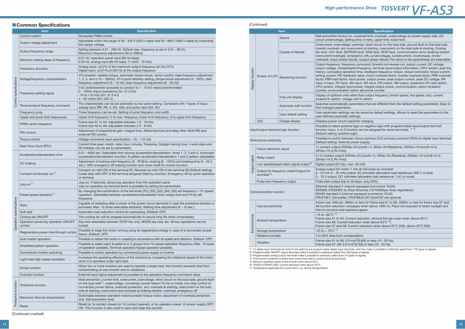
■Common SpecificationsItem Specification
Co
ntr
ol sp
ecific
atio
ns
Control system Sinusoidal PWM control
Output voltage adjustmentAdjustable within the range of 50 - 330 V (240 V class) and 50 - 660 V (480 V class) by correcting the supply voltage
Output frequency rangeSetting between 0.01 - 590 Hz. Default max. frequency is set to 0.01 - 80 Hz. Maximum frequency adjustment (30 to 590Hz)
Minimum setting steps of frequency0.01 Hz: operation panel input (60 Hz base), 0.03 Hz: analog input (60 Hz base, 11 bit/0 - 10 Vdc)
Frequency accuracyAnalog input: ±0.2% of the maximum output frequency (at 25±10°C) Digital input: ±0.01%±0.022 Hz of the output frequency
Voltage/frequency characteristicsV/f constant, variable torque, automatic torque boost, vector control, base frequency adjustment 1, 2, 3, and 4 (15 - 590Hz), V/f 5-point arbitrary setting, torque boost adjustment (0 - 30%), start frequency adjustment (0 - 10 Hz), stop frequency adjustment (0 - 30 Hz)
Frequency setting signal
3 kΩ potentiometer (possible to connect to 1 - 10 kΩ-rated potentiometer) 0 - 10Vdc (input impedance Zin: 31.5 kΩ) -10 to +10 Vdc (Zin: 31.5 kΩ) 4 - 20 mAdc (Zin: 250 Ω)
Terminal block frequency commandThe characteristic can be set arbitrarily by two-point setting. Compliant with 7 types of input; analog input (RR, RX, II, AI4, AI5), and pulse input (S4, S5)
Frequency jump Three frequency can be set. Setting of jump frequency and width.
Upper and lower limit frequencies Upper limit frequency: 0 to max. frequency, lower limit frequency: 0 to upper limit frequency
PWM carrier frequencyFrame size A1 to A4: adjustable between 1.0 - 16 kHz Frame size A5 to A8: adjustable between 2.5 - 8 kHz
PID controlAdjustment of proportional gain, integral time, differential time and delay filter. Multi PID and external PID control.
Torque control Voltage command input specification: -10 - +10 Vdc
Real Time Clock (RTC) Current time (year, month, date, hour, minute), Timezone, Daylight saving time, 4 work days and 20 holidays can be set by parameters
Op
era
tio
n s
pecific
atio
ns
Acceleration/deceleration time0.01 - 6000 sec. Selectable from among acceleration/deceleration. times 1, 2, 3 and 4. Automatic acceleration/deceleration function. S-pattern acceleration/deceleration 1 and 2 pattern adjustable.
DC brakingAdjustment of braking start frequency (0 - [FH]Hz), braking (0 - 100%) and braking time (0 - 25.5 sec.). With emergency off braking function and motor shaft fix control function.
Forward run/reverse run*1 Forward run with ON of the terminal [F], Reverse run with ON of the terminal [R] (Default setting). Coast stop with OFF of the terminal assigned Stad-by function. Emergency off by panel operation or terminal.
Jog run*1 Jog run, if selected, allows jog operation from the operation panel Jog run operation by terminal block is possible by setting the parameters.
Preset speed operation*1By changing the combination of the terminals [S1], [S2], [S3], [S4], [S5] set frequency + 31-speed operation. Selectable between acceleration/deceleration time, torque limit and V/f by set frequency.
RetryCapable of restarting after a check of the power circuit elements in case the protective function is activated. Max. 10 times selectable arbitrarily. Waiting time adjustment (0 - 10 sec.)
Soft stall Automatic load reduction control at overloading. (Default: OFF)
Cooling fan ON/OFF The cooling fan will be stopped automatically to assure long life when unnecessary.
Operation panel key operation ON/OFF control
Key lock selectable between STOP key only, MODE key only, etc. All key operations can be locked.
Regenerative power ride-through control Possible to keep the motor running using its regenerative energy in case of a momentary power failure. (Default: OFF)
Auto-restart operation Possible to restart the motor in coasting in accordance with its speed and direction. (Default: OFF)
Simplified pattern operation Possible to select each 8 patterns in 2 groups from 15-speed operation frequency. Max. 16 types of operation possible. Terminal operation/repeat operation possible.
Commercial inverter switching Possible to switch operation by commercial power supply or inverter
Light-load high-speed operationIncreases the operating efficiency of the machine by increasing the rotational speed of the motor when it is operated under light load.
Droop functionWhen two or more inverters are used to operate a single load, this function prevents load from concentrating on one inverter due to unbalance.
Override function External input signal adjustment is possible to the operation frequency command value.
Pro
tective f
unctio
n
Protective function
Stall prevention, current limit, overcurrent, overvoltage, short circuit on the load side, ground fault on the load side*4, undervoltage, momentary power failure (15 ms or more), non-stop control at momentary power failure, overload protection, arm overload at starting, overcurrent on the load side at starting, overcurrent and overload at braking resistor, overheat, emergency off
Electronic thermal characteristicSwitchable between standard motor/constant torque motor, adjustment of overload protection and stall prevention level.
ResetReset by 1a contact closed (or 1b contact opened), or by operation panel. Or power supply OFF/ON. This function is also used to save and clear trip records.
(Continued overleaf)
14
High-performance Drive
Item Specification
Dis
pla
y f
unctio
n
Screen of LCD
Alarms Stall prevention during run, overload limit, overload, undervoltage on power supply side, DC circuit undervoltage, setting error, in retry, upper limit, lower limit.
Causes of failures
Overcurrent, overvoltage, overheat, short circuit on the load side, ground fault on the load side, inverter overload, arm overcurrent at starting, overcurrent on the load side at starting, Cooling fan fault, CPU fault, EEPROM fault, RAM fault, ROM fault, communication error, (braking resistor overcurrent/overload), (emergency off), (undervoltage), (undercurrent), (overtorque), (motor overload), (input phase failure), (output phase failure) The items in the parentheses are selectable.
Monitoring function
Output frequency, frequency command, forward run/reverse run, output current, DC voltage, output voltage, compensated frequency, terminal input/output information, CPU version, past trip history, cumulative operation time, feedback frequency, torque, torque command, torque current, exiting current, PID feedback value, motor overload factor, inverter overload factor, PBR overload factor, PBR load factor, input power, output power, peak output current, peak DC voltage, RR input, II input, RX input, AI4 input, AI5 input, FM output, AM output, expansion I/O card option CPU version, integral input power, integral output power, communication option reception counter, communication option abnormal counter.
Free unit displayDisplay of optional units other than output frequency (motor speed, line speed, etc), current ampere/% switch, voltage volt/% switch
Automatic edit function Searches automatically parameters that are different from the default setting parameters. Easy to find changed parameters.
User default setting User parameter settings can be saved as default settings. Allows to reset the parameters to the user-defined parameter settings.
LED Charge display Displays power circuit capacitor charging.
Input/output terminal logic functionPossible to select positive logic or negative logic with programmable input/output terminal function menu. 2 or 3 function can be assigned for some terminals. *1 *2 (Default setting: positive logic)
Sink/source switchingPossible to switch between minus common (CC) and plus common (P24) for digital input terminal. (Default setting: external power supply)
outp
ut
sig
nal
Failure detection signal1c contact output (250Vac-2A (cosФ=1), 30Vac-2A (Resistive), 250Vac=1A (cosФ=0.4), 30Vdc=1A (L/R=7ms))
Relay output2×1a contact output (250Vac-2A (cosФ=1), 30Vac-2A (Resistive), 250Vac=1A (cosФ=0.4), 30Vdc=1A (L/R=7ms))
Low speed/speed reach signal output*2 Digital output (24 Vdc, max. 50 mA)
Output for frequency meter/Output for ammeter*3
Analog output for meter: 1 mA dc full-scale dc ammeter 0 - 20 mA (4 - 20 mA) output: DC ammeter (allowable load resistance: 500 Ω or less) 0 - 10 V output: DC voltmeter (allowable load resistance: 1 kΩ or more)
Pulse train frequency output Pulse train output (Up to 30 kpps, duty 50%)
Communication function
Ethernet standard 2-channel equipped (connector: RJ45) IEEE802.3/IEEE802.3u (Fast Ethernet) (10/100Mbps: Auto negotiation)RS485 standard 2-channel equipped (connector: RJ45) PROFINET, DeviceNet, PROFIBUS-DP, EtherCAT are optional.
Enviro
nm
ents
Use environmentsIndoor use. Altitude: 4800m or less for frame size A1 to A6, 3000m or less for frame size A7 and A8 (current reduction necessary when above 1000 m). Place not exposed to direct sunlight and free of corrosive and explosive gases.
Ambient temperature
-15 to +60°C *5
Frame size A1 to A5: Current reduction, remove the top cover when above 50°C; Frame size A6: Current reduction when above 50°C *6;Frame size A7 and A8: Current reduction when above 50°C (HD), above 45°C (ND)
Storage temperature -25 to + 70°C *7
Relative humidity 5 to 95% (free from condensation)
VibrationFrame size A1 to A6: 5.9 m/s2{0.6G} or less (10 - 55 Hz), Frame size A7, A8: 2.9 m/s2{0.3G} or less (10 - 55 Hz)
*1: 14 digital input terminals (of which 6 are options) are programmable digital input terminals, and they make it possible to arbitrarily select from 178 types of signals.
*2: Programmable ON/OFF output terminals make it possible to arbitrarily select from 256 types of signals.
*3: Programmable analog output terminals make it possible to arbitrarily select from 54 types of signals.
*4: This function protects inverters from overcurrent due to output circuit ground fault.
*5: Remove operation panel of the inverter when above 50°C.
*6: VFAS3-4132KPC (ND): Current reduction when above 45°C.
*7: Temperature applicable for a short term. e.g. during transportation
(Continued)
15
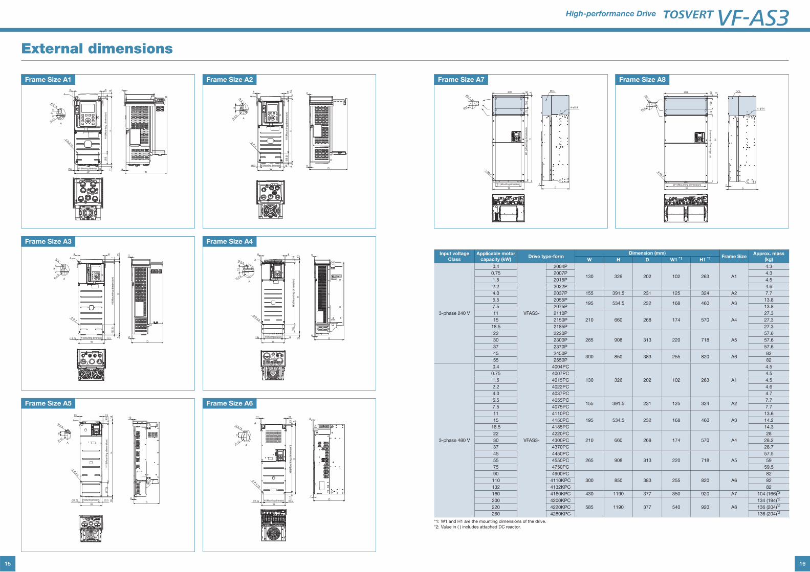
External dimensions
D6
188
13
H11
8H
1(M
ounting
dim
ensio
n)
W1(Mounting dimension)
2-R 2.75
R 2.75
R 5.5
(14) 14
W
(55)
9
A
A
Frame Size A1
D
6
288 1
5H
5
7H
1(M
ounting
dim
ensio
n)
W1(Mounting dimension)
2-R 3
R 3
R 5.5
(13.5) 13.5
W
(67.5
)
9
A
A
D
6
103131
14
H10
15
H1(M
ounting
dim
ensio
n)
W1(Mounting dimension)
2-R 4.5
R 4.5
R 10
(22.5) 22.5
W
(175)
15
A
A
D6
288 1
5H
5
8H
1(M
ounting
dim
ensio
n)
W1(Mounting dimension)
2-R 3
(15) 15
W
(59.5
)
A
R 3
R 5
.5
9
A
D6
388
14
H19
15
H1(M
ounting
dim
ensio
n)
W1(Mounting dimension)
2-R 3.5
R 3.5
R 7.5
(18) 18
W
(75)
10
A
A
D
7
81111
2H
13
H1(M
ounting
dim
ensio
n)
W1(Mounting dimension)
2-R 5.75
R 5.75
R 12
(22.5) 22.5W
(17)
17
A
A
Frame Size A2
Frame Size A3
Frame Size A5
Frame Size A4
Frame Size A6
16
High-performance Drive
440 330
150
75
H1 (M
ounting
dim
ensio
n)
H
2-R5.7
W1 (Mounting dimension)
W D
7
17
R5.7
R12
DCL
4-φ24
W1 (Mounting dimension) 7
DW
2-R5.7
H1 (M
ounting
dim
ensio
n)
H3
75
150
30
R5.7
R12
17
DCL
4-φ24
598
Input voltage
Class
Applicable motor
capacity (kW) Drive type-form
Dimension (mm)Frame Size
Approx. mass
(kg) W H D W1 *1 H1 *1
3-phase 240 V
0.4
VFAS3-
2004P
130 326 202 102 263 A1
4.3
0.75 2007P 4.3
1.5 2015P 4.5
2.2 2022P 4.6
4.0 2037P 155 391.5 231 125 324 A2 7.7
5.5 2055P195 534.5 232 168 460 A3
13.8
7.5 2075P 13.8
11 2110P
210 660 268 174 570 A4
27.3
15 2150P 27.3
18.5 2185P 27.3
22 2220P
265 908 313 220 718 A5
57.6
30 2300P 57.6
37 2370P 57.6
45 2450P300 850 383 255 820 A6
82
55 2550P 82
3-phase 480 V
0.4
VFAS3-
4004PC
130 326 202 102 263 A1
4.5
0.75 4007PC 4.5
1.5 4015PC 4.5
2.2 4022PC 4.6
4.0 4037PC 4.7
5.5 4055PC155 391.5 231 125 324 A2
7.7
7.5 4075PC 7.7
11 4110PC
195 534.5 232 168 460 A3
13.6
15 4150PC 14.2
18.5 4185PC 14.3
22 4220PC
210 660 268 174 570 A4
28
30 4300PC 28.2
37 4370PC 28.7
45 4450PC
265 908 313 220 718 A5
57.5
55 4550PC 59
75 4750PC 59.5
90 4900PC
300 850 383 255 820 A6
82
110 4110KPC 82
132 4132KPC 82
160 4160KPC 430 1190 377 350 920 A7 104 (166)*2
200 4200KPC
585 1190 377 540 920 A8
134 (194)*2
220 4220KPC 136 (204)*2
280 4280KPC 136 (204)*2
*1: W1 and H1 are the mounting dimensions of the drive.
*2: Value in ( ) includes attached DC reactor.
Frame Size A7 Frame Size A8
17
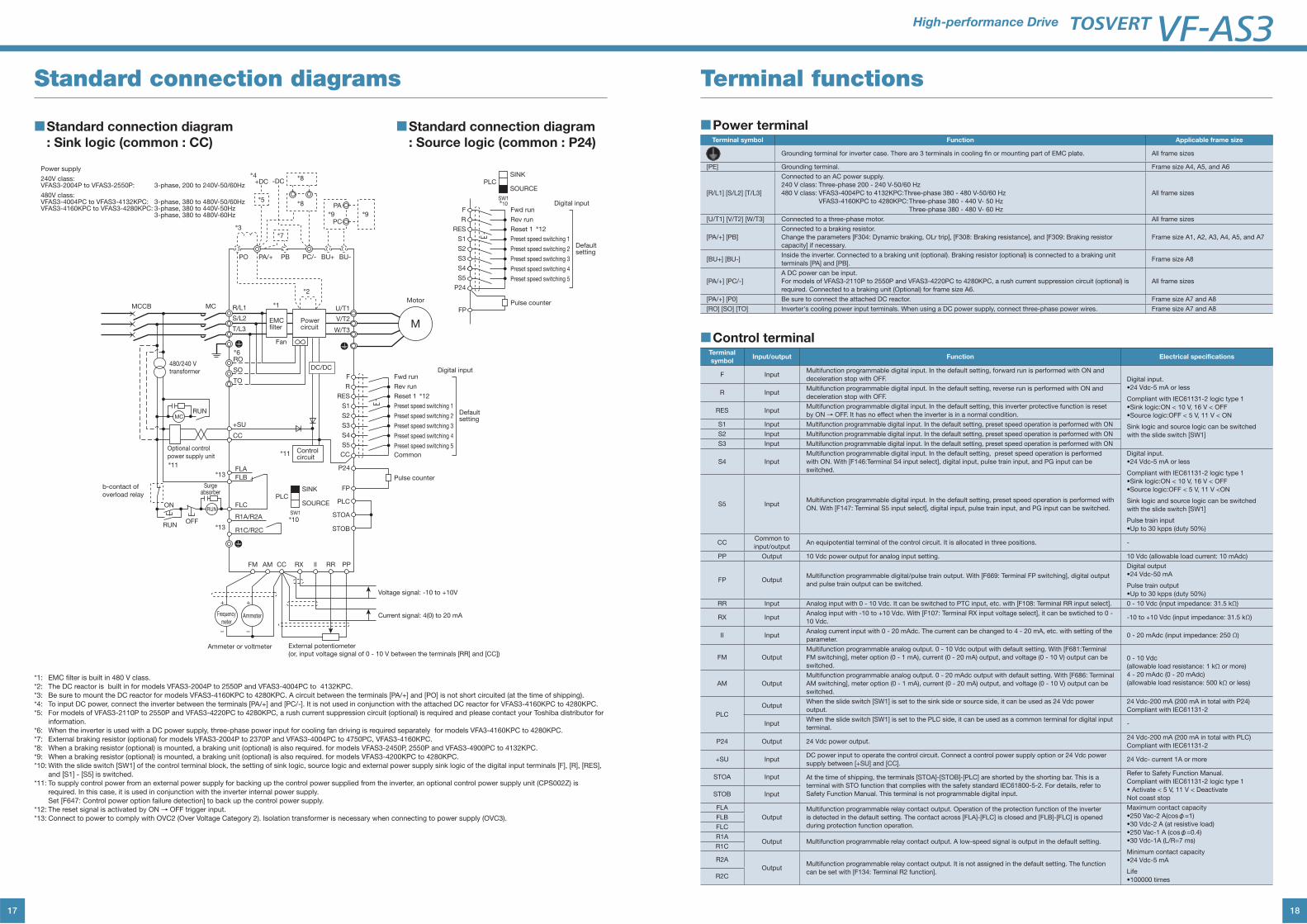
Standard connection diagrams
■Standard connection diagram
: Sink logic (common : CC)
■Standard connection diagram
: Source logic (common : P24)
*1: EMC filter is built in 480 V class.
*2: The DC reactor is built in for models VFAS3-2004P to 2550P and VFAS3-4004PC to 4132KPC.
*3: Be sure to mount the DC reactor for models VFAS3-4160KPC to 4280KPC. A circuit between the terminals [PA/+] and [PO] is not short circuited (at the time of shipping).
*4: To input DC power, connect the inverter between the terminals [PA/+] and [PC/-]. It is not used in conjunction with the attached DC reactor for VFAS3-4160KPC to 4280KPC.
*5: For models of VFAS3-2110P to 2550P and VFAS3-4220PC to 4280KPC, a rush current suppression circuit (optional) is required and please contact your Toshiba distributor for
information.
*6: When the inverter is used with a DC power supply, three-phase power input for cooling fan driving is required separately for models VFA3-4160KPC to 4280KPC.
*7: External braking resistor (optional) for models VFAS3-2004P to 2370P and VFAS3-4004PC to 4750PC, VFAS3-4160KPC.
*8: When a braking resistor (optional) is mounted, a braking unit (optional) is also required. for models VFAS3-2450P, 2550P and VFAS3-4900PC to 4132KPC.
*9: When a braking resistor (optional) is mounted, a braking unit (optional) is also required. for models VFAS3-4200KPC to 4280KPC.
*10: With the slide switch [SW1] of the control terminal block, the setting of sink logic, source logic and external power supply sink logic of the digital input terminals [F], [R], [RES],
and [S1] - [S5] is switched.
*11: To supply control power from an external power supply for backing up the control power supplied from the inverter, an optional control power supply unit (CPS002Z) is
required. In this case, it is used in conjunction with the inverter internal power supply.
Set [F647: Control power option failure detection] to back up the control power supply.
*12: The reset signal is activated by ON→ OFF trigger input.
*13: Connect to power to comply with OVC2 (Over Voltage Category 2). Isolation transformer is necessary when connecting to power supply (OVC3).
Power supply
240V class:VFAS3-2004P to VFAS3-2550P: 3-phase, 200 to 240V-50/60Hz
480V class:VFAS3-4004PC to VFAS3-4132KPC: 3-phase, 380 to 480V-50/60HzVFAS3-4160KPC to VFAS3-4280KPC: 3-phase, 380 to 440V-50Hz 3-phase, 380 to 480V-60Hz
R/L1
RO
SO
TO
S/L2
T/L3
U/T1
V/T2
W/T3
MCCB MC
+
−
PLCPLC
FLA
FLB
+SU
CC
FLC
R1A/R2A
R1C/R2C
SINK
SOURCE
P24
FP
FM AM CC RX RRII PP
RUN
RUN
ON
OFF
MC
RUN
STOB
STOA
M
+
−
SW1
F
R
RES
S1
S3
CC
DC/DC
PO PA/+ PB BU+ BU-PC/-
PA
PC
+DC -DC
*5
*4
*7
*8
*8
*9*9
*3
*2
*6
*11
*12
*11*13
*13
*10
Controlcircuit
Powercircuit
EMCfilter
Fan
Optional control
power supply unit
b-contact of
overload relay
Surgeabsorber
480/240 Vtransformer
Voltage signal: -10 to +10V
Current signal: 4(0) to 20 mA
External potentiometer
(or, input voltage signal of 0 - 10 V between the terminals [RR] and [CC])
Motor
Ammeter or voltmeter
AmmeterFrequency
meter
Fwd runDigital input
Defaultsetting
Rev run
Reset 1
*12
Preset speed switching 1
Preset speed switching 2
Preset speed switching 3
Preset speed switching 4
Preset speed switching 5
S2
S4
S5
Common
Pulse counter
FP
F
R
RES
S1
S3
P24
Fwd runDigital input
Defaultsetting
Rev run
Reset 1
Preset speed switching 1
Preset speed switching 2
Preset speed switching 3
Preset speed switching 4
Preset speed switching 5
S2
S4
S5
Pulse counter
PLCSINK
SOURCE
SW1*10
*1
18
High-performance Drive
Terminal functions
■Power terminalTerminal symbol Function Applicable frame size
Grounding terminal for inverter case. There are 3 terminals in cooling fin or mounting part of EMC plate. All frame sizes
[PE] Grounding terminal. Frame size A4, A5, and A6
[R/L1] [S/L2] [T/L3]
Connected to an AC power supply.
240 V class: Three-phase 200 - 240 V-50/60 Hz
480 V class: VFAS3-4004PC to 4132KPC: Three-phase 380 - 480 V-50/60 Hz
VFAS3-4160KPC to 4280KPC: Three-phase 380 - 440 V- 50 Hz
Three-phase 380 - 480 V- 60 Hz
All frame sizes
[U/T1] [V/T2] [W/T3] Connected to a three-phase motor. All frame sizes
[PA/+] [PB]
Connected to a braking resistor.
Change the parameters [F304: Dynamic braking, OLr trip], [F308: Braking resistance], and [F309: Braking resistor
capacity] if necessary.
Frame size A1, A2, A3, A4, A5, and A7
[BU+] [BU-]Inside the inverter. Connected to a braking unit (optional). Braking resistor (optional) is connected to a braking unit
terminals [PA] and [PB].Frame size A8
[PA/+] [PC/-]
A DC power can be input.
For models of VFAS3-2110P to 2550P and VFAS3-4220PC to 4280KPC, a rush current suppression circuit (optional) is
required. Connected to a braking unit (Optional) for frame size A6.
All frame sizes
[PA/+] [P0] Be sure to connect the attached DC reactor. Frame size A7 and A8
[RO] [SO] [TO] Inverter's cooling power input terminals. When using a DC power supply, connect three-phase power wires. Frame size A7 and A8
■Control terminalTerminal
symbolInput/output Function Electrical specifications
F InputMultifunction programmable digital input. In the default setting, forward run is performed with ON and
deceleration stop with OFF. Digital input.
Compliant with IEC61131-2 logic type 1
Sink logic and source logic can be switched
with the slide switch [SW1]
R InputMultifunction programmable digital input. In the default setting, reverse run is performed with ON and
deceleration stop with OFF.
RES InputMultifunction programmable digital input. In the default setting, this inverter protective function is reset
by ON→ OFF. It has no effect when the inverter is in a normal condition.
S1 Input Multifunction programmable digital input. In the default setting, preset speed operation is performed with ON
S2 Input Multifunction programmable digital input. In the default setting, preset speed operation is performed with ON
S3 Input Multifunction programmable digital input. In the default setting, preset speed operation is performed with ON
S4 Input
Multifunction programmable digital input. In the default setting, preset speed operation is performed
with ON. With [F146:Terminal S4 input select], digital input, pulse train input, and PG input can be
switched.
Digital input.
Compliant with IEC61131-2 logic type 1
Sink logic and source logic can be switched
with the slide switch [SW1]
Pulse train input
S5 InputMultifunction programmable digital input. In the default setting, preset speed operation is performed with
ON. With [F147: Terminal S5 input select], digital input, pulse train input, and PG input can be switched.
CCCommon to
input/outputAn equipotential terminal of the control circuit. It is allocated in three positions. -
PP Output 10 Vdc power output for analog input setting. 10 Vdc (allowable load current: 10 mAdc)
FP OutputMultifunction programmable digital/pulse train output. With [F669: Terminal FP switching], digital output
and pulse train output can be switched.
Digital output
Pulse train output
RR Input Analog input with 0 - 10 Vdc. It can be switched to PTC input, etc. with [F108: Terminal RR input select]. 0 - 10 Vdc (input impedance: 31.5 kΩ)
RX InputAnalog input with -10 to +10 Vdc. With [F107: Terminal RX input voltage select], it can be swtiched to 0 -
10 Vdc.-10 to +10 Vdc (input impedance: 31.5 kΩ)
II InputAnalog current input with 0 - 20 mAdc. The current can be changed to 4 - 20 mA, etc. with setting of the
parameter.0 - 20 mAdc (input impedance: 250 Ω)
FM Output
Multifunction programmable analog output. 0 - 10 Vdc output with default setting. With [F681:Terminal
FM switching], meter option (0 - 1 mA), current (0 - 20 mA) output, and voltage (0 - 10 V) output can be
switched.0 - 10 Vdc
(allowable load resistance: 1 kΩ or more)
4 - 20 mAdc (0 - 20 mAdc)
(allowable load resistance: 500 kΩ or less)AM Output
Multifunction programmable analog output. 0 - 20 mAdc output with default setting. With [F686: Terminal
AM switching], meter option (0 - 1 mA), current (0 - 20 mA) output, and voltage (0 - 10 V) output can be
switched.
PLC
OutputWhen the slide switch [SW1] is set to the sink side or source side, it can be used as 24 Vdc power
output.
24 Vdc-200 mA (200 mA in total with P24)
Compliant with IEC61131-2
InputWhen the slide switch [SW1] is set to the PLC side, it can be used as a common terminal for digital input
terminal.-
P24 Output 24 Vdc power output.24 Vdc-200 mA (200 mA in total with PLC)
Compliant with IEC61131-2
+SU InputDC power input to operate the control circuit. Connect a control power supply option or 24 Vdc power
supply between [+SU] and [CC].24 Vdc- current 1A or more
STOA Input At the time of shipping, the terminals [STOA]-[STOB]-[PLC] are shorted by the shorting bar. This is a
terminal with STO function that complies with the safety standard IEC61800-5-2. For details, refer to
Safety Function Manual. This terminal is not programmable digital input.
Refer to Safety Function Manual.
Compliant with IEC61131-2 logic type 1
Not coast stopSTOB Input
FLA
Output
Multifunction programmable relay contact output. Operation of the protection function of the inverter
is detected in the default setting. The contact across [FLA]-[FLC] is closed and [FLB]-[FLC] is opened
during protection function operation.
Maximum contact capacity
φ=1)
φ=0.4)
Minimum contact capacity
Life
FLB
FLC
R1AOutput Multifunction programmable relay contact output. A low-speed signal is output in the default setting.
R1C
R2A
OutputMultifunction programmable relay contact output. It is not assigned in the default setting. The function
can be set with [F134: Terminal R2 function].R2C
19
When studying how to use our drives
Notes
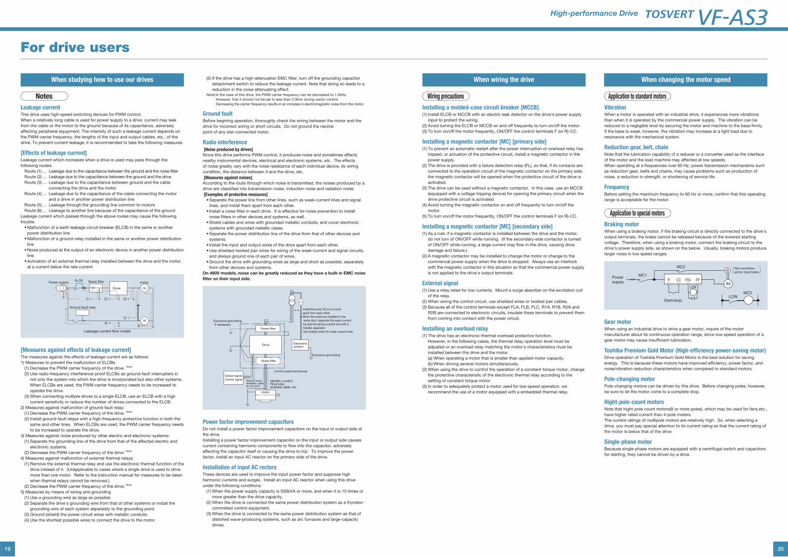
Leakage currentThis drive uses high-speed switching devices for PWM control.
When a relatively long cable is used for power supply to a drive, current may leak
from the cable or the motor to the ground because of its capacitance, adversely
affecting peripheral equipment. The intensity of such a leakage current depends on
the PWM carrier frequency, the lengths of the input and output cables, etc., of the
drive. To prevent current leakage, it is recommended to take the following measures.
[Effects of leakage current]Leakage current which increases when a drive is used may pass through the
following routes:
Route (1) ... Leakage due to the capacitance between the ground and the noise filter
Route (2) ... Leakage due to the capacitance between the ground and the drive
Route (3) ... Leakage due to the capacitance between ground and the cable
connecting the drive and the motor
Route (4) ... Leakage due to the capacitance of the cable connecting the motor
and a drive in another power distribution line
Route (5) ... Leakage through the grounding line common to motors
Route (6) ... Leakage to another line because of the capacitance of the ground
Leakage current which passes through the above routes may cause the following
trouble.
Malfunction of a earth leakage circuit breaker (ELCB) in the same or another
power distribution line
Malfunction of a ground-relay installed in the same or another power distribution
line
Noise produced at the output of an electronic device in another power distribution
line
Activation of an external thermal relay installed between the drive and the motor,
at a current below the rate current
65
4
321
Ground-fault relay
Power supplyELCB Noise filter
Drive
motor
M
M
Leakage current flow routes
[Measures against effects of leakage current]The measures against the effects of leakage current are as follows:
1) Measures to prevent the malfunction of ELCBs
(1) Decrease the PWM carrier frequency of the drive. Note)
(2) Use radio-frequency interference-proof ELCBs as ground-fault interrupters in
not only the system into which the drive is incorporated but also other systems.
When ELCBs are used, the PWM carrier frequency needs to be increased to
operate the drive.
(3) When connecting multiple drives to a single ELCB, use an ELCB with a high
current sensitivity or reduce the number of drives connected to the ELCB.
2) Measures against malfunction of ground-fault relay:
(1) Decrease the PWM carrier frequency of the drive. Note)
(2) Install ground-fault relays with a high-frequency protective function in both the
same and other lines. When ELCBs are used, the PWM carrier frequency needs
to be increased to operate the drive.
3) Measures against noise produced by other electric and electronic systems:
(1) Separate the grounding line of the drive from that of the affected electric and
electronic systems.
(2) Decrease the PWM carrier frequency of the drive. Note)
4) Measures against malfunction of external thermal relays:
(1) Remove the external thermal relay and use the electronic thermal function of the
drive instead of it. (Unapplicable to cases where a single drive is used to drive
more than one motor. Refer to the instruction manual for measures to be taken
when thermal relays cannot be removed.)
(2) Decrease the PWM carrier frequency of the drive. Note)
5) Measures by means of wiring and grounding
(1) Use a grounding wire as large as possible.
(2) Separate the drive's grounding wire from that of other systems or install the
grounding wire of each system separately to the grounding point.
(3) Ground (shield) the power circuit wires with metallic conduits.
(4) Use the shortest possible wires to connect the drive to the motor.
(5) If the drive has a high-attenuation EMC filter, turn off the grounding capacitor
detachment switch to reduce the leakage current. Note that doing so leads to a
reduction in the noise attenuating effect.Note) In the case of this drive, the PWM carrier frequency can be decreased to 1.0kHz.
However, that it should not be set to less than 2.0kHz during vector control.
Decreasing the carrier frequency results in an increase in electromagnetic noise from the motor.
Ground faultBefore begining operation, thoroughly check the wiring between the motor and the
drive for incorrect wiring or short circuits. Do not ground the neutral
point of any star-connected motor.
Radio interference [Noise produced by drives]Since this drive performs PWM control, it produces noise and sometimes affects
nearby instrumental devices, electrical and electronic systems, etc. The effects
of noise greatly vary with the noise resistance of each individual device, its wiring
condition, the distance between it and the drive, etc.
[Measures against noises]According to the route through which noise is transmitted, the noises produced by a
drive are classified into transmission noise, induction noise and radiation noise.
[Examples of protective measures] Separate the power line from other lines, such as weak-current lines and signal
lines, and install them apart from each other.
Install a noise filter in each drive. It is effective for noise prevention to install
noise filters in other devices and systems, as well.
Shield cables and wires with grounded metallic conduits, and cover electronic
systems with grounded metallic cases.
Separate the power distribution line of the drive from that of other devices and
systems.
Install the input and output wires of the drive apart from each other.
Use shielded twisted pair wires for wiring of the weak-current and signal circuits,
and always ground one of each pair of wires.
Ground the drive with grounding wires as large and short as possible, separately
from other devices and systems.
On 480V models, noise can be greatly reduced as they have a built-in EMC noise
filter on their input side.
Exclusive grounding
Electronic system
Control panel enclosure
Metallic conduit, Plica tube, shielded cable, etc
Ground every shielded cable at one point
Drive
Exclusive grounding,
if necessary
Install the wires 30 cm or more
apart from each other.
When the wires are installed in the
same duct, separate the weak-current
ine and the strong-current line with a
metallic separator.
Use twisted wires for weak-current lines.
motor
Noise filter
Noise filter
Sensor signal
Control signal
Power factor improvement capacitorsDo not install a power factor improvement capacitors on the input or output side of
the drive.
Installing a power factor improvement capacitor on the input or output side causes
current containing harmonic components to flow into the capacitor, adversely
affecting the capacitor itself or causing the drive to trip. To improve the power
factor, install an input AC reactor on the primary side of the drive.
Installation of input AC rectorsThese devices are used to improve the input power factor and suppress high
harmonic currents and surges. Install an input AC reactor when using this drive
under the following conditions:
(1) When the power supply capacity is 500kVA or more, and when it is 10 times or
more greater than the drive capacity.
(2) When the drive is connected the same power distribution system as a thyristor-
committed control equipment.
(3) When the drive is connected to the same power distribution system as that of
distorted wave-producing systems, such as arc furnaces and large-capacity
drives.
For drive users
20
High-performance Drive
When wiring the drive
Wiring precautions
Installing a molded-case circuit breaker [MCCB](1) Install ELCB or MCCB with an electric leak detector on the drive's power supply
input to protect the wiring.
(2) Avoid turning the ELCB or MCCB on and off frequently to turn on/off the motor.
(3) To turn on/off the motor frequently, ON/OFF the control terminals F (or R)-CC.
Installing a magnetic contactor [MC] [primary side](1) To prevent an automatic restart after the power interruption or overload relay has
tripped, or actuation of the protective circuit, install a magnetic contactor in the
power supply.
(2) The drive is provided with a failure detection relay (FL), so that, if its contacts are
connected to the operation circuit of the magnetic contactor on the primary side,
the magnetic contactor will be opened when the protective circuit of the drive is
activated.
(3) The drive can be used without a magnetic contactor. In this case, use an MCCB
(equipped with a voltage tripping device) for opening the primary circuit when the
drive protective circuit is activated.
(4) Avoid turning the magnetic contactor on and off frequently to turn on/off the
motor.
(5) To turn on/off the motor frequently, ON/OFF the control terminals F (or R)-CC.
Installing a magnetic contactor [MC] [secondary side](1) As a rule, if a magnetic contactor is installed between the drive and the motor,
do not turn of ON/OFF while running. (If the secondary-side contactor is turned
of ON/OFF while running, a large current may flow in the drive, causing drive
damage and failure.)
(2) A magnetic contactor may be installed to change the motor or change to the
commercial power supply when the drive is stopped. Always use an interlock
with the magnetic contactor in this situation so that the commercial power supply
is not applied to the drive's output terminals.
External signal(1) Use a relay rated for low currents. Mount a surge absorber on the excitation coil
of the relay.
(2) When wiring the control circuit, use shielded wires or twisted pair cables.
(3) Because all of the control terminals except FLA, FLB, FLC, R1A, R1B, R2A and
R2B are connected to electronic circuits, insulate these terminals to prevent them
from coming into contact with the power circuit.
Installing an overload relay(1) The drive has an electronic-thermal overload protective function.
However, in the following cases, the thermal relay operation level must be
adjusted or an overload relay matching the motor's characteristics must be
installed between the drive and the motor.
(a) When operating a motor that is smaller than applied motor capacity.
(b) When driving several motors simultaneously.
(2) When using the drive to control the operation of a constant-torque motor, change
the protective characteristic of the electronic thermal relay according to the
setting of constant torque motor.
(3) In order to adequately protect a motor used for low-speed operation, we
recommend the use of a motor equipped with a embedded thermal relay.
When changing the motor speed
Application to standard motors
VibrationWhen a motor is operated with an industrial drive, it experiences more vibrations
than when it is operated by the commercial power supply. The vibration can be
reduced to a negligible level by securing the motor and machine to the base firmly.
If the base is weak, however, the vibration may increase at a light load due to
resonance with the mechanical system.
Reduction gear, belt, chainNote that the lubrication capability of a reducer or a converter used as the interface
of the motor and the load machine may affected at low speeds.
When operating at a frequencies over 60 Hz, power transmission mechanisms such
as reduction gear, belts and chains, may cause problems such as production of
noise, a reduction in strength, or shortening of service life.
FrequencyBefore setting the maximum frequency to 60 Hz or more, confirm that this operating
range is acceptable for the motor.
Application to special motors
Braking motorWhen using a braking motor, if the braking circuit is directly connected to the drive's
output terminals, the brake cannot be released because of the lowered starting
voltage. Therefore, when using a braking motor, connect the braking circuit to the
drive's power supply side, as shown on the below. Usually, braking motors produce
larger noise in low speed ranges.
Powersupply
MC1
MC2
MC2
F CC P24 FPIM
B
LOW
LOW
Start/stop
Non-excitation
action type brake
Gear motorWhen using an industrial drive to drive a gear motor, inquire of the motor
manufacturer about its continuous operation range, since low-speed operation of a
gear motor may cause insufficient lubrication.
Toshiba Premium Gold Motor (High-efficiency power-saving motor)Drive operation of Toshiba Premium Gold Motor is the best solution for saving
energy. This is because these motors have improved efficiency, power factor, and
noise/vibration reduction characteristics when compared to standard motors.
Pole-changing motorPole-changing motors can be driven by this drive. Before changing poles, however,
be sure to let the motor come to a complete stop.
Hight-pole-count motorsNote that hight-pole count motors(8 or more poles), which may be used for fans,etc.,
have higher rated current than 4-pole moters.
The current ratings of multipole motors are relatively high. So, when selecting a
drive, you must pay special attention to its current rating so that the current rating of
the motor is below that of the drive.
Single-phase motorBecause single-phase motors are equipped with a centrifugal switch and capacitors
for starting, they cannot be driven by a drive.
21
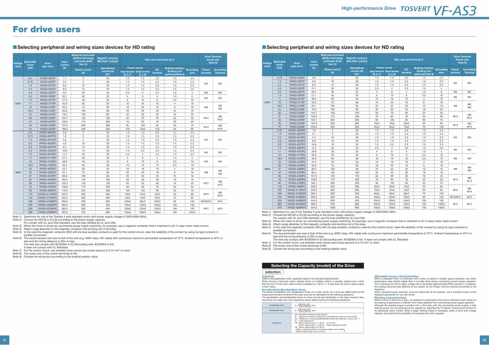
■Selecting peripheral and wiring sizes devices for HD rating
Voltage
class
Applicable
motor
(kW)
Drive
type-form
Input
current
(A)
Molded-case circuit breaker
(MCCB) or Earth leakage
circuit breaker (ELCB)
Note 1),2)
Magnetic contactor
(MC) Note 1),3),4),5)Wire size (mm) Note 6),7)
Drive Terminal
Screw size
Note 8)
Rated current
(A)
Operational
current (A)
AC1
Power circuitDC
terminal
Braking resistor/
Braking unit
(optional) Note 9)
Grounding
wire
Power
terminal
Grounding
TerminalInput terminal
(R, S, T)
Output terminal
(U, V, W)
240V
0.4 VFAS3-2004P 1.7 3 20 1.5 1.5 2.5 1.5 2.5
M4 M50.75 VFAS3-2007P 3.3 5 20 1.5 1.5 2.5 1.5 2.5
1.5 VFAS3-2015P 6.0 10 20 1.5 1.5 2.5 1.5 2.5
2.2 VFAS3-2022P 9.0 15 20 1.5 1.5 2.5 1.5 2.5
4.0 VFAS3-2037P 15.1 20 20 2.5 4 2.5 1.5 4 M4 M5
5.5 VFAS3-2055P 20.1 30 32 4 6 4 1.5 6M5 M5
7.5 VFAS3-2075P 27.3 40 32 6 10 6 2.5 10
11 VFAS3-2110P 40.0 50 50 10 16 10 4 16
M8M6
M815 VFAS3-2150P 53.2 75 60 16 25 16 6 16
18.5 VFAS3-2185P 64.8 100 80 25 35 25 10 16
22 VFAS3-2220P 78.3 100 80 35 50 35 16 25
M12M8
M1230 VFAS3-2300P 104.7 150 150 50 70 50 25 35
37 VFAS3-2370P 128.4 175 200 70 95 70 35 50
45 VFAS3-2450P 157.6 200 260 95 120 95 50 70M10
M8
M1055 VFAS3-2550P 189.0 250 260 120 70x2 120 50 95
480V
0.4 VFAS3-4004PC 0.9 3 20 1.5 1.5 2.5 1.5 2.5
M4 M5
0.75 VFAS3-4007PC 1.8 3 20 1.5 1.5 2.5 1.5 2.5
1.5 VFAS3-4015PC 3.2 5 20 1.5 1.5 2.5 1.5 2.5
2.2 VFAS3-4022PC 4.9 10 20 1.5 1.5 2.5 1.5 2.5
4.0 VFAS3-4037PC 8.3 10 20 1.5 1.5 2.5 1.5 2.5
5.5 VFAS3-4055PC 10.9 15 20 1.5 2.5 2.5 1.5 2.5M4 M5
7.5 VFAS3-4075PC 14.7 20 20 2.5 4 2.5 1.5 2.5
11 VFAS3-4110PC 21.4 30 32 4 6 4 1.5 4
M5 M515 VFAS3-4150PC 28.9 40 32 6 10 6 2.5 10
18.5 VFAS3-4185PC 35.4 50 50 10 10 10 2.5 10
22 VFAS3-4220PC 42.1 60 50 16 16 10 4 16
M8M6
M830 VFAS3-4300PC 57.1 75 60 25 25 16 6 16
37 VFAS3-4370PC 69.9 100 80 25 35 25 10 16
45 VFAS3-4450PC 84.8 125 100 35 35 35 16 16
M12M8
M1255 VFAS3-4550PC 103.3 125 135 50 50 50 16 25
75 VFAS3-4750PC 139.8 175 200 95 95 70 35 50
90 VFAS3-4900PC 170.2 225 260 120 120 95 35 70
M10M8
M10110 VFAS3-4110KPC 203.5 250 260 70x2 70x2 70x2 50 95
132 VFAS3-4132KPC 240.3 300 260 70x2 70x2 70x2 70 95
160 VFAS3-4160KPC 290.0 350 350 120x2 95x2 150x2 95 120 M10/M12 M12
200 VFAS3-4200KPC 360.0 500 450 150x2 120x2 150x3 150 150
M12 M12220 VFAS3-4220KPC 395.0 500 450 150x3 120x2 150x3 150 150
280 VFAS3-4280KPC 495.0 700 660 150x3 185x2 150x4 150 120x2
Note 1) Selections for use of the Toshiba 4-pole standard motor with power supply voltage of 200V/400V-50Hz.Note 2) Choose the MCCB or ELCB according to the power supply capacity. For comply with UL and CSA standard, use the fuse certified by UL and CSA.Note 3) When the motor is driven by commercial power supply switching, for example, use a magnetic contactor that is matched to AC-3 class motor rated current.Note 4) Attach surge absorber to the magnetic contactor and exciting coil of the relay.Note 5) In the case the magnetic contactor (MC) with 2a-type auxiliary contacts is used for the control circuit, raise the reliability of the contact by using 2a-type contacts in
parallel connection.Note 6) The recommended wire size is that of the wire (e.g. 600V class, HIV cable) with continuous maximum permissible temperature of 75°C. Ambient temperature is 40°C or
less and the wiring distance is 30m or less. The wire size comply with IEC60364-5-52 (Grounding wire: IEC60364-5-54). It does not comply with UL Standard.Note 7) For the control circuit, use shielded wires whose size (cross-section) is 0.75 mm2 or more.Note 8) The screw size of the control terminals is M3.Note 9) Choose the wiring size according to the braking resistor value.
For drive users
22
High-performance Drive
■Selecting peripheral and wiring sizes devices for ND rating
Voltage
class
Applicable
motor
(kW)
Drive
type-form
Input
current
(A)
Molded-case circuit breaker
(MCCB) or Earth leakage
circuit breaker (ELCB)
Note 1),2)
Magnetic contactor
(MC) Note 1),3),4),5)Wire size (mm) Note 6),7)
Drive Terminal
Screw size
Note 8)
Rated current
(A)
Operational
current (A)
AC1
Power circuitDC
terminal
Braking resistor/
Braking unit
(optional) Note 9)
Grounding
wire
Power
terminal
Grounding
TerminalInput terminal
(R, S, T)
Output terminal
(U, V, W)
240V
0.75 VFAS3-2004P 3.0 5 20 1.5 1.5 2.5 1.5 2.5
M4 M51.5 VFAS3-2007P 5.9 10 20 1.5 1.5 2.5 1.5 2.5
2.2 VFAS3-2015P 8.5 15 20 1.5 1.5 2.5 1.5 2.5
4.0 VFAS3-2022P 15.1 20 20 2.5 4 2.5 1.5 4
5.5 VFAS3-2037P 20.2 30 32 4 6 4 1.5 6 M4 M5
7.5 VFAS3-2055P 27.1 40 32 6 10 6 2.5 10M5 M5
11 VFAS3-2075P 39.3 50 50 10 16 10 4 16
15 VFAS3-2110P 53.0 75 60 16 25 16 6 16
M8M6
M818.5 VFAS3-2150P 65.1 100 80 25 35 25 10 16
22 VFAS3-2185P 76.0 100 80 35 50 35 16 25
30 VFAS3-2220P 104.7 150 150 50 70 50 25 35
M12M8
M1237 VFAS3-2300P 128.0 175 200 70 95 70 35 50
45 VFAS3-2370P 154.7 200 260 95 120 95 50 70
55 VFAS3-2450P 191.9 250 260 70x2 70x2 50x2 50 95M10
M8
M1075 VFAS3-2550P 256.0 350 350 95x2 95x2 70x2 70 120
480V
0.75 VFAS3-4004PC 1.6 3 20 1.5 1.5 2.5 1.5 2.5
M4 M5
1.5 VFAS3-4007PC 3.1 5 20 1.5 1.5 2.5 1.5 2.5
2.2 VFAS3-4015PC 4.5 10 20 1.5 1.5 2.5 1.5 2.5
4.0 VFAS3-4022PC 8.0 10 20 1.5 1.5 2.5 1.5 2.5
5.5 VFAS3-4037PC 10.8 15 20 1.5 2.5 2.5 1.5 2.5
7.5 VFAS3-4055PC 14.4 20 20 2.5 4 2.5 1.5 2.5M4 M5
11 VFAS3-4075PC 20.8 30 32 4 6 4 1.5 4
15 VFAS3-4110PC 28.3 40 32 6 10 6 2.5 10
M5 M518.5 VFAS3-4150PC 34.9 50 50 10 10 10 2.5 10
22 VFAS3-4185PC 41.4 50 50 10 16 10 4 16
30 VFAS3-4220PC 55.9 75 60 16 25 16 6 16
M8M6
M837 VFAS3-4300PC 69.0 100 80 25 35 25 10 16
45 VFAS3-4370PC 83.4 125 100 35 35 35 16 16
55 VFAS3-4450PC 101.9 125 135 50 50 50 16 25
M12M8
M1275 VFAS3-4550PC 138.0 175 200 70 95 70 35 50
90 VFAS3-4750PC 165.1 200 260 95 120 95 35 70
110 VFAS3-4900PC 203.5 250 260 50x2 50x2 70x2 35 95
M10M8
M10132 VFAS3-4110KPC 240.3 300 260 70x2 70x2 70x2 50 95
160 VFAS3-4132KPC 284.2 350 350 95x2 95x2 95x2 70 120
220 VFAS3-4160KPC 395.0 500 450 150x2 150x2 150x2 95 150 M10/M12 M12
250 VFAS3-4200KPC 444.0 500 450 150x2 150x2 150x2 150 150
M12 M12280 VFAS3-4220KPC 495.0 700 660 150x3 120x3 150x3 150 120x2
315 VFAS3-4280KPC 555.0 1000 660 150x3 150x3 150x3 150 120x2
Note 1) Selections for use of the Toshiba 4-pole standard motor with power supply voltage of 200V/400V-50Hz.Note 2) Choose the MCCB or ELCB according to the power supply capacity. For comply with UL and CSA standard, use the fuse certified by UL and CSA.Note 3) When the motor is driven by commercial power supply switching, for example, use a magnetic contactor that is matched to AC-3 class motor rated current.Note 4) Attach surge absorber to the magnetic contactor and exciting coil of the relay.Note 5) In the case the magnetic contactor (MC) with 2a-type auxiliary contacts is used for the control circuit, raise the reliability of the contact by using 2a-type contacts in
parallel connection.Note 6) The recommended wire size is that of the wire (e.g. 600V class, HIV cable) with continuous maximum permissible temperature of 75°C. Ambient temperature is 40°C or
less and the wiring distance is 30m or less. The wire size comply with IEC60364-5-52 (Grounding wire: IEC60364-5-54). It does not comply with UL Standard.Note 7) For the control circuit, use shielded wires whose size (cross-section) is 0.75 mm2 or more.Note 8) The screw size of the control terminals is M3.Note 9) Choose the wiring size according to the braking resistor value.
CapacityRefer to the applicable motor capacities listed in the standard specifications. When driving a high-pole motor, special motor, or multiple motors in parallel, select such a drive that the sum of the motor rated current multiplied by 1.05 to 1.1 is less than the drive's rated output current value.
Acceleration/deceleration timesThe actual acceleration and deceleration times of a motor driven by a drive are determined by the torque and moment of inertia of the load, and can be calculated by the following equations. The acceleration and deceleration times of a drive can be set individually. In any case, however, they should be set longer than their respective values determined by the following equations.
Allowable torque characteristicsWhen a standard motor is combined with a drive to perform variable speed operation, the motor temperature rises slightly higher than it normally does during commercial power supply operation. This is because the drive output voltage has a sinusoidal (approximate) PWM waveform. In addition, the cooling becomes less effective at low speed, so the torque must be reduced according to the frequency. When constant-torque operation must be performed at low speeds, use a constant-torque motor designed specifically for use with drives.
Starting characteristicsWhen a motor is driven by a drive, its operation is restricted by the drive’s overload current rating, so the starting characteristic is different from those obtained from commercial power supply operation. Although the starting torque is smaller with a drive than with the commercial power supply, a high starting torque can be produced at low speeds by adjusting the V/f pattern torque boost amount or by employing vector control. When a larger starting torque is necessary, select a drive with a larger capacity and examine the possibility of increasing the motor capacity.
Selecting the Capacity (model) of the Drive
selection
Acceleration time ta = (JM+JL) x ΔN
(sec.) 9.56 x (TM–TL)
Deceleration time ta = (JM +JL) x ΔN
(sec.) 9.56 x (TB+TL)
Conditions
JM : Moment of inertia of motor (kg.m2)JL : Moment of inertia of load (kg.m2) (converted into value on motor shaft)ΔN : Difference in rotating speed between before and after acc. or dce. (min.–1)TL : Load torque (N.m)TM : Motor rated torque x 1.1 (N.m) ... V/f control : Motor rated torque x 1.2 (N.m) ... Vector operation controlTB : Motor rated torque x 0.2 (N.m) When a braking resistor or a braking resistor unit is used: Motor rated torque x 0.8-1.0 (N.m) )(
23
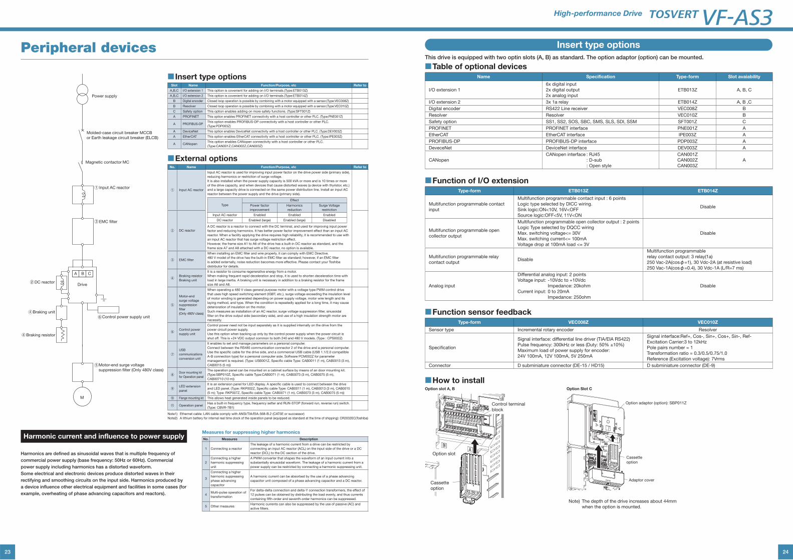
Peripheral devices
■ Insert type optionsSlot Name Function/Purpose, etc Refer to
A,B,C I/O extension 1 This option is covenient for adding on I/O terminals.(Type:ETB013Z)
A,B,C I/O extension 2 This option is covenient for adding on I/O terminals.(Type:ETB014Z)
B Digital encoder Closed loop operation is possible by combining with a motor equipped with a sensor.(Type:VEC008Z)
B Resolver Closed loop operation is possible by combining with a motor equipped with a sensor.(Type:VEC010Z)
C Safety option This option enables adding on more safety functions. (Type:SFT001Z)
A PROFINET This option enables PROFINET connectivity with a host controller or other PLC. (Type:PNE001Z)
A PROFIBUS-DPThis option enables PROFIBUS-DP connectivity with a host controller or other PLC.
(Type:PDP003Z)
A DeviceNet This option enables DeviceNet connectivity with a host controller or other PLC. (Type:DEV003Z)
A EtherCAT This option enables EtherCAT connectivity with a host controller or other PLC. (Type:IPE003Z)
A CANopenThis option enables CANopen connectivity with a host controller or other PLC.
(Type:CAN001Z,CAN002Z,CAN003Z)
■External optionsNo. Name Function/Purpose, etc Refer to
① Input AC reactor
Input AC reactor is used for improving input power factor on the drive power side (primary side),
reducing harmonics or restriction of surge voltage.
It is also installed when the power supply capacity is 500 kVA or more and is 10 times or more
of the drive capacity, and when devices that cause distorted waves (a device with thyristor, etc.)
and a large capacity drive is connected on the same power distribution line. Install an input AC
reactor between the power supply and the drive (primary side).
Type
Effect
Power factor
improvement
Harmonics
reduction
Surge Voltage
restriction
Input AC reactor Enabled Enabled Enabled
DC reactor Enabled (large) Enabled (large) Disabled
A DC reactor is a reactor to connect with the DC terminal, and used for improving input power
factor and reducing harmonics. It has better power factor improvement effect than an input AC
reactor. When a facility applying the drive requires high reliability, it is recommended to use with
an input AC reactor that has surge voltage restriction effect.
However, the frame size A1 to A6 of the drive has a built-in DC reactor as standard, and the
frame size A7 and A8 attached with a DC reactor, no option is available.
② DC reactor
③ EMC filter
When installing an EMC filter and wire properly, it can comply with EMC Directive.
480 V model of the drive has the built-in EMC filter as standard; however, if an EMC filter
is added externally, noise reduction becomes more effective. Please contact your Toshiba
distributor for details.
④ Braking resistor
Braking unit
It is a resistor to consume regenerative energy from a motor.
When making frequent rapid deceleration and stop, it is used to shorten deceleration time with
load in large inertia. A braking unit is necessary in addition to a braking resistor for the frame
size A6 and A8.
⑤
Motor-end
surge voltage
suppression
filter
(Only 480V class)
When operating a 480 V class general purpose motor with a voltage type PWM control drive
that uses high speed switching element (IGBT, etc.), surge voltage exceeding the insulation level
of motor winding is generated depending on power supply voltage, motor wire length and its
laying method, and type. When the condition is repeatedly applied for a long time, it may cause
deterioration of insulation on the motor.
Such measures as installation of an AC reactor, surge voltage suppression filter, sinusoidal
filter on the drive output side (secondary side), and use of a high insulation strength motor are
necessity.
⑥ Control power
supply unit
Control power need not be input separately as it is supplied internally on the drive from the
power circuit power supply.
Use this option when backing up only by the control power supply when the power circuit is
shut off. This is +24 VDC output common to both 240 and 480 V models. (Type : CPS002Z)
⑦USB
communications
conversion unit
It enables to set and manage parameters on a personal computer.
Connect between the RS485 communication connector 2 of the drive and a personal computer.
Use the specific cable for the drive side, and a commercial USB cable (USB 1.1/2.0 compatible
A-B connection type) for a personal computer side. Software PCM002Z for parameter
management is required. (Type: USB001Z, Specific cable Type: CAB0011 (1 m), CAB0013 (3 m),
CAB0015 (5 m))
⑧ Door mounting kit
for Operation panel
The operation panel can be mounted on a cabinet surface by means of an door mounting kit.
(Type:SBP010Z, Specific cable Type:CAB0071 (1 m), CAB0073 (3 m), CAB0075 (5 m),
CAB00710 (10 m))
⑨ LED extension
panel
It is an extension panel for LED display. A specific cable is used to connect between the drive
and LED panel. (Type: RKP002Z, Specific cable Type: CAB0011 (1 m), CAB0013 (3 m), CAB0015
(5 m); Type: RKP007Z, Specific cable Type: CAB0071 (1 m), CAB0073 (3 m), CAB0075 (5 m))
⑩ Flange mounting kit This allows heat generated inside panels to be reduced.
⑪ Operation panelHas a built-in frequency type, frequency setter and RUN-STOP (forward run, reverse run) switch.
(Type: CBVR-7B1)
Note1) Ethernet cable: LAN cable comply with ANSI/TIA/EIA-568-B.2 (CAT5E or successor)
Note2) A lithium battery for internal real time clock of the operation panel (equipped as standard at the time of shipping): CR2032EC(Toshiba)
Input AC reactor
Molded-case circuit breaker MCCB
or Earth leakage circuit breaker (ELCB)
Power supply
Magnetic contactor MC
DC reactorDrive
Control power supply unitBraking unit
Motor-end surge voltage
suppression filter (Only 480V class)
M
3
5
4
4
6
Braking resistor
2
1
EMC filter
A B C
Harmonic current and influence to power supply
Harmonics are defined as sinusoidal waves that is multiple frequency of
commercial power supply (base frequency: 50Hz or 60Hz). Commercial
power supply including harmonics has a distorted waveform.
Some electrical and electronic devices produce distorted waves in their
rectifying and smoothing circuits on the input side. Harmonics produced by
a device influence other electrical equipment and facilities in some cases (for
example, overheating of phase advancing capacitors and reactors).
Measures for suppressing higher harmonics
No. Measures Description
1 Connecting a reactor
The leakage of a harmonic current from a drive can be restricted by
connecting an input AC reactor (ACL) on the input side of the drive or a DC
reactor (DCL) to the DC section of the drive.
2
Connecting a higher
harmonic suppressing
unit
A PWM converter that shapes the waveform of an input current into a
substantially sinusoidal waveform. The leakage of a harmonic current from a
power supply can be restricted by connecting a harmonic suppressing unit.
3
Connecting a higher
harmonic suppressing
phase advancing
capacitor
A harmonic current can be absorbed by the use of a phase advancing
capacitor unit composed of a phase advancing capacitor and a DC reactor.
4Multi-pulse operation of
transformation
For delta-delta connection and delta-Y connection transformers, the effect of
12 pulses can be obtained by distributing the load evenly, and thus currents
containing fifth-order and seventh-order harmonics can be suppressed.
5 Other measuresHarmonic currents can also be suppressed by the use of passive (AC) and
active filters.
24
High-performance Drive
This drive is equipped with two optin slots (A, B) as standard. The option adaptor (option) can be mounted.
■Table of optional devicesName Specification Type-form Slot avaiability
I/O extension 1
6x digital input
2x digital output
2x analog input
ETB013Z A, B, C
I/O extension 2 3x 1a relay ETB014Z A, B ,C
Digital encoder RS422 Line receiver VEC008Z B
Resolver Resolver VEC010Z B
Safety option SS1, SS2, SOS, SBC, SMS, SLS, SDI, SSM SFT001Z C
PROFINET PROFINET interface PNE001Z A
EtherCAT EtherCAT interface IPE003Z A
PROFIBUS-DP PROFIBUS-DP interface PDP003Z A
DeveceNet DeviceNet interface DEV003Z A
CANopen
CANopen interface : RJ45
: D-sub
: Open style
CAN001Z
CAN002Z
CAN003Z
A
■Function of I/O extensionType-form ETB013Z ETB014Z
Multifunction programmable contact
input
Multifunction programmable contact input : 6 points
Logic type selected by DICC wiring.
Disable
Multifunction programmable open
collector output
Multifunction programmable open collector output : 2 points
Logic Type selected by DQCC wiring
Disable
Multifunction programmable relay
contact outputDisable
Multifunction programmable
relay contact output: 3 relay(1a)
250 Vac-2A(cosφ=1), 30 Vdc-2A (at resistive load)
250 Vac-1A(cosφ=0.4), 30 Vdc-1A (L/R=7 ms)
Analog input
Differential analog input: 2 points
Voltage input: -10Vdc to +10Vdc Impedance: 20kohm
Current input: 0 to 20mA Impedance: 250ohm
Disable
■Function sensor feedbackType-form VEC008Z VEC010Z
Sensor type Incremental rotary encoder Resolver
Specification
Signal interface: differential line driver (TIA/EIA RS422)
Pulse frequency: 300kHz or less (Duty: 50% ±10%)
Maximum load of power supply for encoder:
24V 100mA, 12V 100mA, 5V 250mA
Signal interface:Ref+, Cos-, Sin+, Cos+, Sin-, Ref-
Excitation Carrier:3 to 12kHz
Pole pairs number = 1
Transformation ratio = 0.3/0.5/0.75/1.0
Reference (Excitation voltage): 7Vrms
Connector D subminiature connector (DE-15 / HD15) D subminiature connector (DE-9)
■How to installOption slot A, B Option Slot C
Cassette
option
Option slot
Control terminal
block
Cassette
Option adaptor (option): SBP011Z
option
Adaptor cover
Note) The depth of the drive increases about 44mm
when the option is mounted.
Insert type options
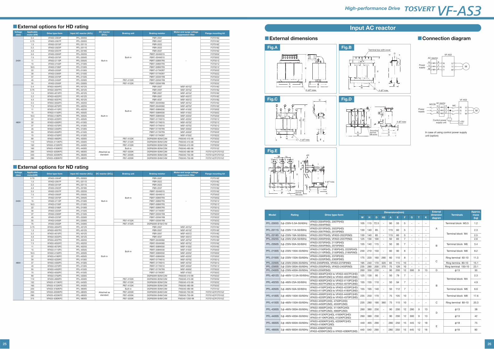
25
■External options for HD ratingVoltage
class
Applicable
motor (kW)Drive type-form Input AC reactor (ACL)
DC reactor
(DCL)Braking unit Braking resistor
Motor-end surge voltage
suppression filterFlange mounting kit
240V
0.4 VFAS3-2004P PFL-2005S
Buit-in
Built-in
PBR-2007
-
FOT018Z
0.75 VFAS3-2007P PFL-2005S PBR-2007 FOT018Z
1.5 VFAS3-2015P PFL-2011S PBR-2022 FOT018Z
2.2 VFAS3-2022P PFL-2011S PBR-2022 FOT018Z
4.0 VFAS3-2037P PFL-2018S PBR-2037 FOT019Z
5.5 VFAS3-2055P PFL-2025S PBR7-004W015 FOT020Z
7.5 VFAS3-2075P PFL-2050S PBR7-004W015 FOT020Z
11 VFAS3-2110P PFL-2050S PBR7-008W7R5 FOT021Z
15 VFAS3-2150P PFL-2100S PBR7-008W7R5 FOT021Z
18.5 VFAS3-2185P PFL-2100S PBR7-008W7R5 FOT021Z
22 VFAS3-2220P PFL-2100S PBR7-017W3R7 FOT022Z
30 VFAS3-2300P PFL-2150S PBR7-017W3R7 FOT022Z
37 VFAS3-2370P PFL-2150S PBR7-035W1R8 FOT022Z
45 VFAS3-2450P PFL-2200S PB7-4132K PBR7-035W1R8 FOT023Z
55 VFAS3-2550P PFL-2300S PB7-4132K PBR7-035W1R8 FOT023Z
480V
0.4 VFAS3-4004PC PFL-4012S
Built-in
Built-in
PBR-2007 MSF-4015Z FOT018Z
0.75 VFAS3-4007PC PFL-4012S PBR-2007 MSF-4015Z FOT018Z
1.5 VFAS3-4015PC PFL-4012S PBR-2007 MSF-4015Z FOT018Z
2.2 VFAS3-4022PC PFL-4012S PBR-2007 MSF-4037Z FOT018Z
4.0 VFAS3-4037PC PFL-4012S PBR-4037 MSF-4037Z FOT018Z
5.5 VFAS3-4055PC PFL-4025S PBR7-004W060 MSF-4075Z FOT019Z
7.5 VFAS3-4075PC PFL-4025S PBR7-004W060 MSF-4075Z FOT019Z
11 VFAS3-4110PC PFL-4025S PBR7-008W030 MSF-4150Z FOT020Z
15 VFAS3-4150PC PFL-4050S PBR7-008W030 MSF-4150Z FOT020Z
18.5 VFAS3-4185PC PFL-4050S PBR7-008W030 MSF-4220Z FOT020Z
22 VFAS3-4220PC PFL-4050S PBR7-017W015 MSF-4220Z FOT021Z
30 VFAS3-4300PC PFL-4100S PBR7-017W015 MSF-4370Z FOT021Z
37 VFAS3-4370PC PFL-4100S PBR7-017W010 MSF-4370Z FOT021Z
45 VFAS3-4450PC PFL-4100S PBR7-017W7R5 MSF-4550Z FOT022Z
55 VFAS3-4550PC PFL-4150S PBR7-017W7R5 MSF-4550Z FOT022Z
75 VFAS3-4750PC PFL-4150S PBR7-017W3R7 MSF-4750Z FOT022Z
90 VFAS3-4900PC PFL-4300S PB7-4132K DGP600W-B2M/C2M FN5040-410-99 FOT023Z
110 VFAS3-4110KPC PFL-4300S PB7-4132K DGP600W-B2M/C2M FN5040-410-99 FOT023Z
132 VFAS3-4132KPC PFL-4400S PB7-4132K DGP600W-B2M/C2M FN5040-410-99 FOT023Z
160 VFAS3-4160KPC PFL-4400S
Attached as
standard
Built-in DGP600W-B2M/C2M FN5040-480-99 FOT013Z
200 VFAS3-4200KPC PFL-4600S PB7-4200K DGP600W-B3M/C3M FN5040-480-99 FOT014Z/FOT015Z
220 VFAS3-4220KPC PFL-4600S PB7-4200K DGP600W-B3M/C3M FN5040-750-99 FOT014Z/FOT015Z
280 VFAS3-4280KPC PFL-4800S PB7-4200K DGP600W-B4M/C4M FN5040-750-99 FOT014Z/FOT015Z
■External options for ND ratingVoltage
class
Applicable
motor(kW)Drive type-form Input AC reactor (ACL) DC reactor (DCL) Braking unit Braking resistor
Motor-end surge voltage
suppression filterFlange mounting kit
240V
0.75 VFAS3-2004P PFL-2005S
Buit-in
Built-in
PBR-2007
-
FOT018Z
1.5 VFAS3-2007P PFL-2011S PBR-2022 FOT018Z
2.2 VFAS3-2015P PFL-2011S PBR-2022 FOT018Z
4.0 VFAS3-2022P PFL-2018S PBR-2037 FOT018Z
5.5 VFAS3-2037P PFL-2025S PBR7-004W015 FOT019Z
7.5 VFAS3-2055P PFL-2050S PBR7-004W015 FOT020Z
11 VFAS3-2075P PFL-2050S PBR7-008W7R5 FOT020Z
15 VFAS3-2110P PFL-2100S PBR7-008W7R5 FOT021Z
18.5 VFAS3-2150P PFL-2100S PBR7-008W7R5 FOT021Z
22 VFAS3-2185P PFL-2100S PBR7-008W7R5 FOT021Z
30 VFAS3-2220P PFL-2150S PBR7-017W3R7 FOT022Z
37 VFAS3-2300P PFL-2150S PBR7-035W1R8 FOT022Z
45 VFAS3-2370P PFL-2200S PBR7-035W1R8 FOT022Z
55 VFAS3-2450P PFL-2300S PB7-4132K PBR7-035W1R8 FOT023Z
75 VFAS3-2550P PFL-2400S PB7-4132K DGP600W-B1M/C1M FOT023Z
480V
0.75 VFAS3-4004PC PFL-4012S
Built-in
Built-in
PBR-2007 MSF-4015Z FOT018Z
1.5 VFAS3-4007PC PFL-4012S PBR-2007 MSF-4015Z FOT018Z
2.2 VFAS3-4015PC PFL-4012S PBR-2007 MSF-4037Z FOT018Z
4.0 VFAS3-4022PC PFL-4012S PBR-4037 MSF-4037Z FOT018Z
5.5 VFAS3-4037PC PFL-4025S PBR7-004W060 MSF-4075Z FOT018Z
7.5 VFAS3-4055PC PFL-4025S PBR7-004W060 MSF-4075Z FOT019Z
11 VFAS3-4075PC PFL-4025S PBR7-008W030 MSF-4150Z FOT019Z
15 VFAS3-4110PC PFL-4050S PBR7-008W030 MSF-4150Z FOT020Z
18.5 VFAS3-4150PC PFL-4050S PBR7-008W030 MSF-4220Z FOT020Z
22 VFAS3-4185PC PFL-4050S PBR7-008W030 MSF-4220Z FOT020Z
30 VFAS3-4220PC PFL-4100S PBR7-017W015 MSF-4370Z FOT021Z
37 VFAS3-4300PC PFL-4100S PBR7-017W015 MSF-4370Z FOT021Z
45 VFAS3-4370PC PFL-4100S PBR7-017W010 MSF-4550Z FOT021Z
55 VFAS3-4450PC PFL-4150S PBR7-017W7R5 MSF-4550Z FOT022Z
75 VFAS3-4550PC PFL-4150S PBR7-017W3R7 MSF-4750Z FOT022Z
90 VFAS3-4750PC PFL-4300S DGP600W-B2M/C2M FN5040-410-99 FOT022Z
110 VFAS3-4900PC PFL-4300S PB7-4132K DGP600W-B2M/C2M FN5040-410-99 FOT023Z
132 VFAS3-4110KPC PFL-4400S PB7-4132K DGP600W-B2M/C2M FN5040-410-99 FOT023Z
160 VFAS3-4132KPC PFL-4400S PB7-4132K DGP600W-B2M/C2M FN5040-480-99 FOT023Z
220 VFAS3-4160KPC PFL-4600S
Attached as
standard
Built-in DGP600W-B3M/C3M FN5040-480-99 FOT013Z
250 VFAS3-4200KPC PFL-4800S PB7-4200K DGP600W-B4M/C4M FN5040-750-99 FOT014Z/FOT015Z
280 VFAS3-4220KPC PFL-4800S PB7-4200K DGP600W-B4M/C4M FN5040-750-99 FOT014Z/FOT015Z
315 VFAS3-4280KPC PFL-4800S PB7-4200K DGP600W-B4M/C4M FN5040-1200-99 FOT014Z/FOT015Z
26
High-performance Drive
■External dimensions ■Connection diagram
Input AC reactor
A
W
H
D
4-φF holes
Fig.A
AW
H H2
D
4-φF holes
Fig.C
A
W
EDG
H
φK
4-φF holes
Grounding terminalM8 screw
Fig.E
AW
H
D
4-φF holes
Terminal box with coverFig.B
A
W
E
D
G
H
Grounding terminalM8 screw
4-φF holes
Fig.D
In case of using control power supply
unit (option)
Powersupply
Powersupply
AC reactor
R
S
T
U
V
W
U
V
W
X
Y
ZM
AC reactor
Control powersupply unit
MCCBMC
R
VF-AS3
S
T
+SUCC
U
V
W
U
V
W
X
Y
ZM
VF-AS3
Model Rating Drive type-formDimensions(mm) External
dimension
diagram
Terminals
Approx.
mass
(kg)W H D H2 A E F G T K
PFL-2005S 3φ-230V-5.5A-50/60HzVFAS3-2004P(HD), 2007P(HD)
VFAS3-2004P(ND)105 115 72.5 - 90 55 5 - - -
A
Terminal block M3.5 1.2
PFL-2011S 3φ-230V-11A-50/60HzVFAS3-2015P(HD), 2022P(HD)
VFAS3-2007P(ND), 2015P(ND)130 140 85 - 115 60 5 - - -
Terminal block M4
2.3
PFL-2018S 3φ-230V-18A-50/60Hz VFAS3-2037P(HD), VFAS3-2022P(ND) 130 140 85 - 115 60 5 - - - 2.5
PFL-2025S 3φ-230V-25A-50/60Hz VFAS3-2055P(HD), VFAS3-2037P(ND) 125 130 100 - 50 83 7 - - -
B
2.6
PFL-2050S 3φ-230V-50A-50/60HzVFAS3-2075P(HD), 2110P(HD)
VFAS3-2055P(ND), 2075P(ND)155 140 115 - 50 95 7 - - - Terminal block M6 3.4
PFL-2100S 3φ-230V-100A-50/60HzVFAS3-2150P(HD), 2185P(HD), 2220P(HD)
VFAS3-2110P(ND), 2150P(ND), 2185P(ND)230 210 150 - 60 90 8 - - - Terminal block M8 8.2
PFL-2150S 3φ-230V-150A-50/60HzVFAS3-2300P(HD), 2370P(HD)
VFAS3-2220P(ND), 2300P(ND)175 220 160 290 60 110 8 - - -
C
Ring terminal 60-10 11.3
PFL-2200S 3φ-230V-200A-50/60Hz VFAS-2450P(HD), VFAS3-2370P(ND) 195 240 170 320 65 115 10 - - - Ring termina 80-10 15.1
PFL-2300S 3φ-230V-300A-50/60Hz VFAS3-2550P(HD), VFAS3-2450P(ND) 235 280 200 370 75 128 10 - - - Ring terminal 150-10 23.1
PFL-2400S 3φ-230V-400A-50/60Hz VFAS3-2550P(ND) 260 330 230 - 90 200 12 300 9 13 D φ13 30
PFL-4012S 3φ-460V-12.5A-50/60HzVFAS3-4004PC(HD) to VFAS3-4037PC(HD)
VFAS3-4004PC(ND) to VFAS3-4022PC(ND)125 130 95 - 50 79 7 - - -
B
Terminal block M4
2.3
PFL-4025S 3φ-460V-25A-50/60HzVFAS3-4055PC(HD) to VFAS3-4110PC(HD)
VFAS3-4037PC(ND) to VFAS3-4075PC(ND)155 155 110 - 50 94 7 - - - 4.9
PFL-4050S 3φ-460V-50A-50/60HzVFAS3-4150PC(HD) to VFAS3-4220PC(HD)
VFAS3-4110PC(ND) to VFAS3-4185PC(ND)155 165 140 - 50 112 7 - - - Terminal block M6 6.6
PFL-4100S 3φ-460V-100A-50/60HzVFAS3-4300PC(HD) to VFAS3-4450PC(HD)
VFAS3-4220PC(ND) to VFAS3-4370PC(ND)235 250 170 - 75 105 10 - - - Terminal block M8 17.6
PFL-4150S 3φ-460V-150A-50/60HzVFAS3-4550PC(HD), 4750PC(HD)
VFAS3-4450PC(ND), 4550PC(ND)235 280 190 360 75 115 10 - - - C Ring terminal 80-10 20.3
PFL-4300S 3φ-460V-300A-50/60HzVFAS3-4900PC(HD), 4110KPC(HD)
VFAS3-4750PC(ND), 4900PC(ND)260 380 230 - 90 200 12 280 9 13
D
φ13 38
PFL-4400S 3φ-460V-400A-50/60HzVFAS3-4132KPC(HD), 4160KPC(HD)
VFAS3-4110KPC(ND), 4132KPC(ND)260 380 230 - 90 200 12 300 9 13 φ13 42
PFL-4600S 3φ-460V-600A-50/60HzVFAS3-4200KPC(HD), 4220KPC(HD)
VFAS3-4160KPC(ND)440 465 290 - 280 250 15 445 12 18
E
φ18 75
PFL-4800S 3φ-460V-800A-50/60HzVFAS3-4280KPC(HD)
VFAS3-4200KPC(ND) to VFAS3-4280KPC(ND)440 540 290 - 280 250 15 445 12 18 φ18 90
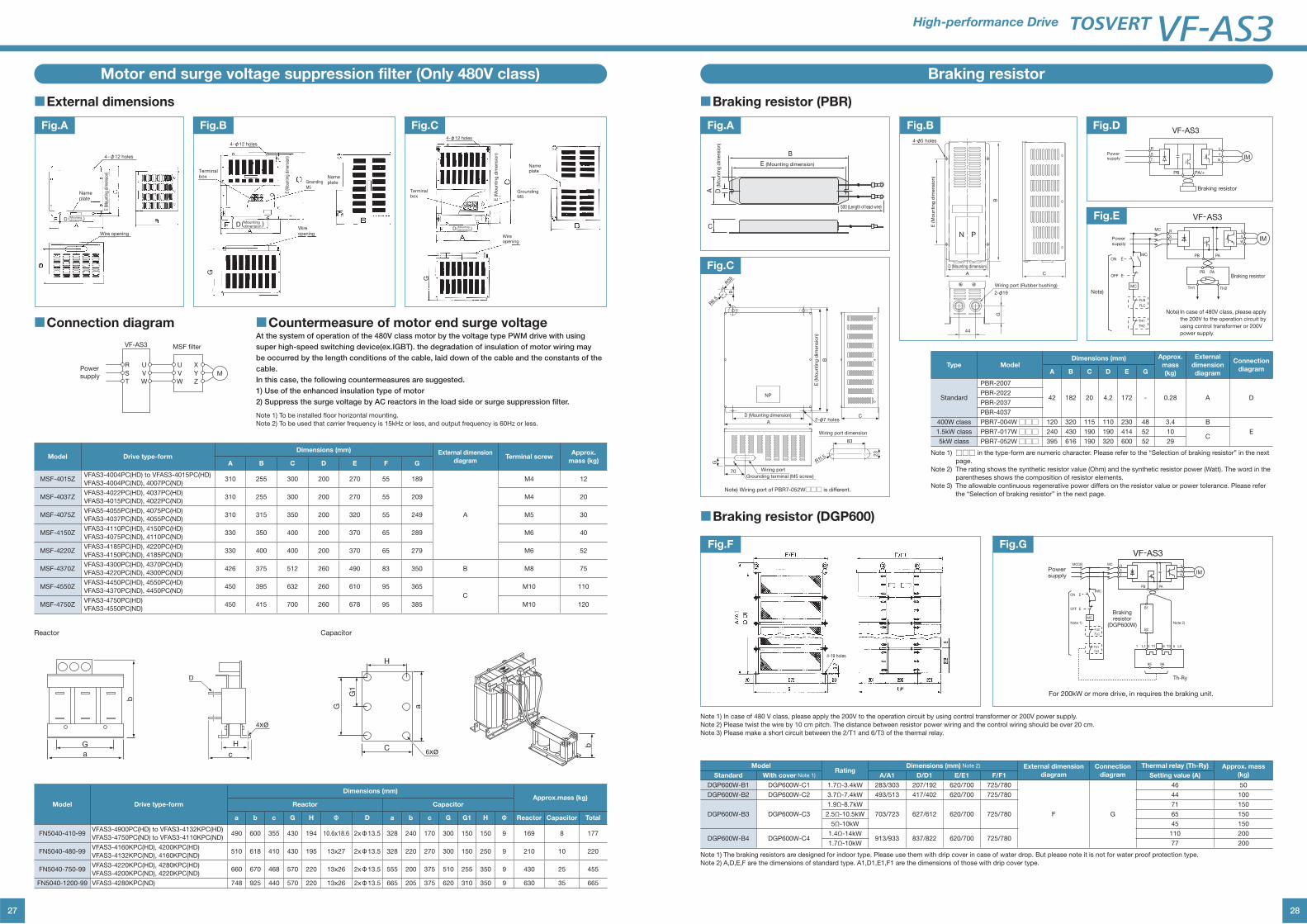
27
Motor end surge voltage suppression filter (Only 480V class)
■External dimensions
■Connection diagram ■Countermeasure of motor end surge voltageAt the system of operation of the 480V class motor by the voltage type PWM drive with using
super high-speed switching device(ex.IGBT). the degradation of insulation of motor wiring may
be occurred by the length conditions of the cable, laid down of the cable and the constants of the
cable.
In this case, the following countermeasures are suggested.
1) Use of the enhanced insulation type of motor
2) Suppress the surge voltage by AC reactors in the load side or surge suppression filter.
Note 1) To be installed floor horizontal mounting.
Note 2) To be used that carrier frequency is 15kHz or less, and output frequency is 60Hz or less.
4-φ12 holes
Nameplate
E (M
ount
ing
dim
ensi
on)
D ( )Mountingdimension
Wire opening
Fig.A
Nameplate
Wireopening
G
D ( )Mounting dimension
4-φ12 holes
GroundingM5
E (M
ount
ing
dim
ensi
on)
Terminal box
Fig.B
G
Wireopening
Terminalbox
4-φ12 holes
E (M
ou
ntin
g d
imen
sio
n)
GroundingM5
D ( )Mounting dimension
Nameplate
Fig.C
Powersupply
MSF filter
R
VF-AS3
S
T
U
V
W
M
U
V
W
X
Y
Z
Model Drive type-formDimensions (mm) External dimension
diagramTerminal screw
Approx.
mass (kg)A B C D E F G
MSF-4015ZVFAS3-4004PC(HD) to VFAS3-4015PC(HD)
VFAS3-4004PC(ND), 4007PC(ND)310 255 300 200 270 55 189
A
M4 12
MSF-4037ZVFAS3-4022PC(HD), 4037PC(HD)
VFAS3-4015PC(ND), 4022PC(ND)310 255 300 200 270 55 209 M4 20
MSF-4075ZVFAS5-4055PC(HD), 4075PC(HD)
VFAS3-4037PC(ND), 4055PC(ND)310 315 350 200 320 55 249 M5 30
MSF-4150ZVFAS3-4110PC(HD), 4150PC(HD)
VFAS3-4075PC(ND), 4110PC(ND)330 350 400 200 370 65 289 M6 40
MSF-4220ZVFAS3-4185PC(HD), 4220PC(HD)
VFAS3-4150PC(ND), 4185PC(ND)330 400 400 200 370 65 279 M6 52
MSF-4370ZVFAS3-4300PC(HD), 4370PC(HD)
VFAS3-4220PC(ND), 4300PC(ND)426 375 512 260 490 83 350 B M8 75
MSF-4550ZVFAS3-4450PC(HD), 4550PC(HD)
VFAS3-4370PC(ND), 4450PC(ND)450 395 632 260 610 95 365
C
M10 110
MSF-4750ZVFAS3-4750PC(HD)
VFAS3-4550PC(ND)450 415 700 260 678 95 385 M10 120
Model Drive type-form
Dimensions (mm)Approx.mass (kg)
Reactor Capacitor
a b c G H Φ D a b c G G1 H Φ Reactor Capacitor Total
FN5040-410-99VFAS3-4900PC(HD) to VFAS3-4132KPC(HD)
VFAS3-4750PC(ND) to VFAS3-4110KPC(ND)490 600 355 430 194 10.6x18.6 2xΦ13.5 328 240 170 300 150 150 9 169 8 177
FN5040-480-99VFAS3-4160KPC(HD), 4200KPC(HD)
VFAS3-4132KPC(ND), 4160KPC(ND)510 618 410 430 195 13x27 2xΦ13.5 328 220 270 300 150 250 9 210 10 220
FN5040-750-99VFAS3-4220KPC(HD), 4280KPC(HD)
VFAS3-4200KPC(ND), 4220KPC(ND)660 670 468 570 220 13x26 2xΦ13.5 555 200 375 510 255 350 9 430 25 455
FN5040-1200-99 VFAS3-4280KPC(ND) 748 925 440 570 220 13x26 2xΦ13.5 665 205 375 620 310 350 9 630 35 665
D
4xø
H
c
G
a
b
Reactor Capacitor
a
H
G1
G
C b
6xø
28
High-performance Drive
Braking resistor
■Braking resistor (PBR)
■Braking resistor (DGP600)
B
C
A
E (Mounting dimension)
D (M
ou
ntin
g d
imen
sio
n)
500 (Length of lead wire)
Fig.A
Note) Wiring port of PBR7-052W□□□ is different.
83
2-φ7 holesA
D (Mounting dimension)
E (M
ounting
dim
ensio
n)
NP
C
70 Wiring port
Grounding terminal (M5 screw)
Wiring port dimension
R11.5
R6.
5
R35
23
B
G
9
44
Wiring port (Rubber bushing)
2-φ19
A
N P
C
D (Mounting dimension)
BG
4-φ5 holes
E (M
ou
ntin
g d
imen
sio
n)
Fig.B
4-19 holes
Fig.F
For 200kW or more drive, in requires the braking unit.
IM
U
V
W
PAPB
B1
B2
1 L1 5 L32
95 96
T1 6 T3
Brakingresistor
(DGP600W)
Th-Ry
R
S
T
MC
MC
MC
E
E
ON
OFF
FLB
FLC
TH1
TH2
Powersupply
Note 1) Note 2)
VF-AS3MCCB
Fig.G
VF-AS3
R
S
U
VIMT
PA/+
Braking resistor
Powersupply
PB
W
Fig.D
VF-AS3
IM
U
V
W
PA
PA
PB
PB
TH2TH1
Braking resistor
R
S
T
MC
MC
MC
E
E
ON
OFF
FLB
FLC
TH1
TH2
Power
supply
Note)
Fig.E
Type ModelDimensions (mm) Approx.
mass
(kg)
External
dimension
diagram
Connection
diagramA B C D E G
Standard
PBR-2007
42 182 20 4.2 172 - 0.28 A DPBR-2022
PBR-2037
PBR-4037
400W class PBR7-004W□□□ 120 320 115 110 230 48 3.4 B
E1.5kW class PBR7-017W□□□ 240 430 190 190 414 52 10C
5kW class PBR7-052W□□□ 395 616 190 320 600 52 29
Note 1) □□□ in the type-form are numeric character. Please refer to the “Selection of braking resistor” in the next
page.
Note 2) The rating shows the synthetic resistor value (Ohm) and the synthetic resistor power (Watt). The word in the
parentheses shows the composition of resistor elements.
Note 3) The allowable continuous regenerative power differs on the resistor value or power tolerance. Please refer
the “Selection of braking resistor” in the next page.
ModelRating
Dimensions (mm) Note 2) External dimension
diagram
Connection
diagram
Thermal relay (Th-Ry) Approx. mass
(kg)Standard With cover Note 1) A/A1 D/D1 E/E1 F/F1 Setting value (A)
DGP600W-B1 DGP600W-C1 1.7Ω-3.4kW 283/303 207/192 620/700 725/780
F G
46 50
DGP600W-B2 DGP600W-C2 3.7Ω-7.4kW 493/513 417/402 620/700 725/780 44 100
DGP600W-B3 DGP600W-C3
1.9Ω-8.7kW
703/723 627/612 620/700 725/780
71 150
2.5Ω-10.5kW 65 150
5Ω-10kW 45 150
DGP600W-B4 DGP600W-C41.4Ω-14kW
913/933 837/822 620/700 725/780110 200
1.7Ω-10kW 77 200
Note 1) In case of 480 V class, please apply the 200V to the operation circuit by using control transformer or 200V power supply.
Note 2) Please twist the wire by 10 cm pitch. The distance between resistor power wiring and the control wiring should be over 20 cm.
Note 3) Please make a short circuit between the 2/T1 and 6/T3 of the thermal relay.
Note 1) The braking resistors are designed for indoor type. Please use them with drip cover in case of water drop. But please note it is not for water proof protection type.
Note 2) A,D,E,F are the dimensions of standard type. A1,D1,E1,F1 are the dimensions of those with drip cover type.
Fig.C
Note) In case of 480V class, please apply
the 200V to the operation circuit by
using control transformer or 200V
power supply.
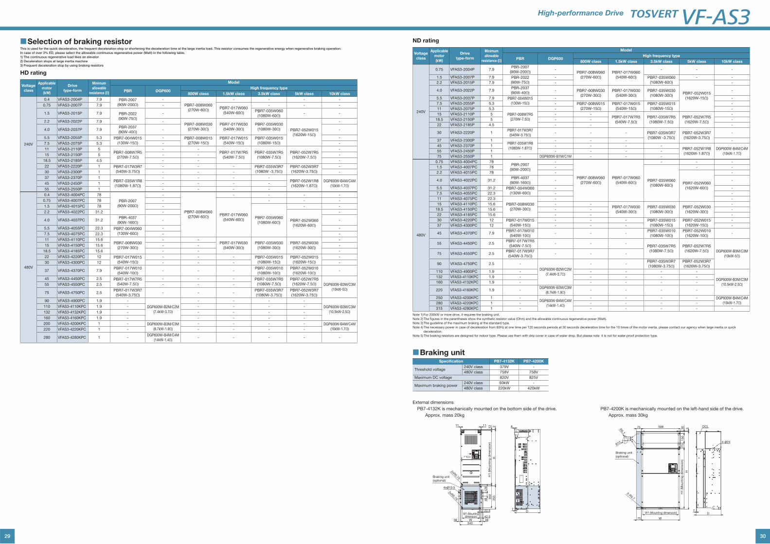
29
■Selection of braking resistorThis is used for the quick deceleration, the frequent deceleration stop or shortening the deceleration time at the large inertia load. This resistor consumes the regenerative energy when regenerative braking operation.
In case of over 3% ED, please select the allowable continuous regenerative power (Watt) in the following table.
1) The continuous regenerative load likes an elevator
2) Deceleration stops at large inertia machine
3) Frequent deceleration stop by using braking resistors
HD rating
Voltage
class
Applicable
motor
(kW)
Drive
type-form
Minimum
allowable
resistance (Ω)
Model
PBR DGP600High frequency type
800W class 1.5kW class 3.5kW class 5kW class 10kW class
240V
0.4 VFAS3-2004P 7.9 PBR-2007
(90W-200Ω)
-
PBR7-008W060
(270W-60Ω)
- - - -
0.75 VFAS3-2007P 7.9 -PBR7-017W060
(540W-60Ω)
- - -
1.5 VFAS3-2015P 7.9 PBR-2022
(90W-75Ω)
-PBR7-035W060
(1080W-60Ω)- -
2.2 VFAS3-2022P 7.9 -PBR7-008W030
(270W-30Ω)
PBR7-017W030
(540W-30Ω)
PBR7-035W030
(1080W-30Ω) PBR7-052W015
(1620W-15Ω)
-
4.0 VFAS3-2037P 7.9PBR-2037
(90W-40Ω)- -
5.5 VFAS3-2055P 5.3 PBR7-004W015
(130W-15Ω)
- PBR7-008W015
(270W-15Ω)
PBR7-017W015
(540W-15Ω)
PBR7-035W015
(1080W-15Ω)
-
7.5 VFAS3-2075P 5.3 - -
11 VFAS3-2110P 5PBR7-008W7R5
(270W-7.5Ω)
- -PBR7-017W7R5
(540W-7.5Ω)
PBR7-035W7R5
(1080W-7.5Ω)
PBR7-052W7R5
(1620W-7.5Ω)
-
15 VFAS3-2150P 5 - - -
18.5 VFAS3-2185P 4.5 - - -
22 VFAS3-2220P 1 PBR7-017W3R7
(540W-3.75Ω)
- - - PBR7-035W3R7
(1080W -3.75Ω)
PBR7-052W3R7
(1620W-3.75Ω)
-
30 VFAS3-2300P 1 - - - -
37 VFAS3-2370P 1PBR7-035W1R8
(1080W-1.87Ω)
- - - -PBR7-052W1R8
(1620W-1.87Ω)
DGP600W-B4M/C4M
(10kW-1.7Ω)45 VFAS3-2450P 1 - - - -
55 VFAS3-2550P 1 - - - -
480V
0.4 VFAS3-4004PC 78
PBR-2007
(90W-200Ω)
-
PBR7-008W060
(270W-60Ω)
- - - -
0.75 VFAS3-4007PC 78 -
PBR7-017W060
(540W-60Ω)
- - -
1.5 VFAS3-4015PC 78 -
PBR7-035W060
(1080W-60Ω)
- -
2.2 VFAS3-4022PC 31.2 -
PBR7-052W060
(1620W-60Ω)
-
4.0 VFAS3-4037PC 31.2PBR-4037
(90W-160Ω)- -
5.5 VFAS3-4055PC 22.3 PBR7-004W060
(130W-60Ω)
- -
7.5 VFAS3-4075PC 22.3 - -
11 VFAS3-4110PC 15.6PBR7-008W030
(270W-30Ω)
- -PBR7-017W030
(540W-30Ω)
PBR7-035W030
(1080W-30Ω)
PBR7-052W030
(1620W-30Ω)
-
15 VFAS3-4150PC 15.6 - - -
18.5 VFAS3-4185PC 15.6 - - -
22 VFAS3-4220PC 12 PBR7-017W015
(540W-15Ω)
- - - PBR7-035W015
(1080W-15Ω)
PBR7-052W015
(1620W-15Ω)
-
30 VFAS3-4300PC 12 - - - -
37 VFAS3-4370PC 7.9PBR7-017W010
(540W-10Ω)- - -
PBR7-035W010
(1080W-10Ω)
PBR7-052W010
(1620W-10Ω)-
45 VFAS3-4450PC 2.5 PBR7-017W7R5
(540W-7.5Ω)
- - - PBR7-035W7R5
(1080W-7.5Ω)
PBR7-052W7R5
(1620W-7.5Ω) DGP600W-B3M/C3M
(10kW-5Ω)
55 VFAS3-4550PC 2.5 - - -
75 VFAS3-4750PC 2.5PBR7-017W3R7
(540W-3.75Ω)- - -
PBR7-035W3R7
(1080W-3.75Ω)
PBR7-052W3R7
(1620W-3.75Ω)
90 VFAS3-4900PC 1.9 -
DGP600W-B2M/C2M
(7.4kW-3.7Ω)
- - - -
DGP600W-B3M/C3M
(10.5kW-2.5Ω)
110 VFAS3-4110KPC 1.9 - - - - -
132 VFAS3-4132KPC 1.9 - - - - -
160 VFAS3-4160KPC 1.9 - - - - -
200 VFAS3-4200KPC 1 - DGP600W-B3M/C3M
(8.7kW-1.9Ω)
- - - - DGP600W-B4M/C4M
(10kW-1.7Ω)220 VFAS3-4220KPC 1 - - - - -
280 VFAS3-4280KPC 1 -DGP600W-B4M/C4M
(14kW-1.4Ω)- - - - -
30
High-performance Drive
ND rating
Voltage
class
Applicable
motor
(kW)
Drive
type-form
Minimum
allowable
resistance (Ω)
Model
PBR DGP600High frequency type
800W class 1.5kW class 3.5kW class 5kW class 10kW class
240V
0.75 VFAS3-2004P 7.9PBR-2007
(90W-200Ω)-
PBR7-008W060
(270W-60Ω)
PBR7-017W060
(540W-60Ω)
- - -
1.5 VFAS3-2007P 7.9 PBR-2022
(90W-75Ω)
- PBR7-035W060
(1080W-60Ω)
- -
2.2 VFAS3-2015P 7.9 -
PBR7-052W015
(1620W-15Ω)
-
4.0 VFAS3-2022P 7.9PBR-2037
(90W-40Ω)- PBR7-008W030
(270W-30Ω)
PBR7-017W030
(540W-30Ω)
PBR7-035W030
(1080W-30Ω)
-
5.5 VFAS3-2037P 7.9 PBR7-004W015
(130W-15Ω)
- -
7.5 VFAS3-2055P 5.3 - PBR7-008W015
(270W-15Ω)
PBR7-017W015
(540W-15Ω)
PBR7-035W015
(1080W-15Ω)
-
11 VFAS3-2075P 5.3
PBR7-008W7R5
(270W-7.5Ω)
- -
15 VFAS3-2110P 5 - -PBR7-017W7R5
(540W-7.5Ω)
PBR7-035W7R5
(1080W-7.5Ω)
PBR7-052W7R5
(1620W-7.5Ω)
-
18.5 VFAS3-2150P 5 - - -
22 VFAS3-2185P 4.5 - - -
30 VFAS3-2220P 1PBR7-017W3R7
(540W-3.75Ω)- - - PBR7-035W3R7
(1080W -3.75Ω)
PBR7-052W3R7
(1620W-3.75Ω)
-
37 VFAS3-2300P 1PBR7-035W1R8
(1080W-1.87Ω)
- - - -
45 VFAS3-2370P 1 - - - -PBR7-052W1R8
(1620W-1.87Ω)
DGP600W-B4M/C4M
(10kW-1.7Ω)55 VFAS3-2450P 1 - - - -
75 VFAS3-2550P 1 - DGP600W-B1M/C1M - - -
480V
0.75 VFAS3-4004PC 78PBR-2007
(90W-200Ω)
-
PBR7-008W060
(270W-60Ω)
PBR7-017W060
(540W-60Ω)
- - -
1.5 VFAS3-4007PC 78 -
PBR7-035W060
(1080W-60Ω)
- -
2.2 VFAS3-4015PC 78 -
PBR7-052W060
(1620W-60Ω)
-
4.0 VFAS3-4022PC 31.2PBR-4037
(90W-160Ω)- -
5.5 VFAS3-4037PC 31.2 PBR7-004W060
(130W-60Ω)
- -
7.5 VFAS3-4055PC 22.3 - -
11 VFAS3-4075PC 22.3
PBR7-008W030
(270W-30Ω)
- -
15 VFAS3-4110PC 15.6 - -PBR7-017W030
(540W-30Ω)
PBR7-035W030
(1080W-30Ω)
PBR7-052W030
(1620W-30Ω)
-
18.5 VFAS3-4150PC 15.6 - - -
22 VFAS3-4185PC 15.6 - - -
30 VFAS3-4220PC 12 PBR7-017W015
(540W-15Ω)
- - - PBR7-035W015
(1080W-15Ω)
PBR7-052W015
(1620W-15Ω)
-
37 VFAS3-4300PC 12 - - - -
45 VFAS3-4370PC 7.9PBR7-017W010
(540W-10Ω)- - -
PBR7-035W010
(1080W-10Ω)
PBR7-052W010
(1620W-10Ω)-
55 VFAS3-4450PC 2.5PBR7-017W7R5
(540W-7.5Ω)- - -
PBR7-035W7R5
(1080W-7.5Ω)
PBR7-052W7R5
(1620W-7.5Ω) DGP600W-B3M/C3M
(10kW-5Ω)75 VFAS3-4550PC 2.5
PBR7-017W3R7
(540W-3.75Ω)- - -
90 VFAS3-4750PC 2.5 -
DGP600W-B2M/C2M
(7.4kW-3.7Ω)
- -PBR7-035W3R7
(1080W-3.75Ω)
PBR7-052W3R7
(1620W-3.75Ω)
110 VFAS3-4900PC 1.9 - - - - -
DGP600W-B3M/C3M
(10.5kW-2.5Ω)
132 VFAS3-4110KPC 1.9 - - - - -
160 VFAS3-4132KPC 1.9 - - - - -
220 VFAS3-4160KPC 1.9 -DGP600W-B3M/C3M
(8.7kW-1.9Ω)- - - -
250 VFAS3-4200KPC 1 -DGP600W-B4M/C4M
(14kW-1.4Ω)
- - - - DGP600W-B4M/C4M
(10kW-1.7Ω)280 VFAS3-4220KPC 1 - - - - -
315 VFAS3-4280KPC 1 - - - - - -
Note 1) For 200kW or more drive, it requires the braking unit.
Note 2) The figures in the parentheses show the synthetic resistor value (Ohm) and the allowable continuous regenerative power (Watt).
Note 3) The guideline of the maximum braking at the standard type.
Note 4) The necessary power in case of deceleration from 60Hz at one time per 120 seconds periods at 30 seconds deceleration time for the 10 times of the motor inertia. please contact our agency when large inertia or quick
deceleration.
Note 5) The braking resistors are designed for indoor type. Please use them with drip cover in case of water drop. But please note it is not for water proof protection type.
■Braking unitSpecification PB7-4132K PB7-4200K
Threshold voltage240V class 379V -
480V class 758V 758V
Maximum DC voltage 820V 825V
Maximum braking power 240V class 93kW -
480V class 220kW 420kW
W1 (Mounting dimension)7
D
W
2-R5.7
H1 (M
ounting
dim
ensio
n)
H3
75
150
30
R5.7
R12
17
59875
75
DCL
Braking unit
(optional)
4-φ24
PB7-4200K is mechanically mounted on the left-hand side of the drive.
Approx. mass 30kg
External dimensions
PB7-4132K is mechanically mounted on the bottom side of the drive.
Approx. mass 20kg
8
7D
1111 213
H1 (M
ounting
dim
ensio
n)
H353
350
126
48
42.5W1 (Mounting
dimension)
340
22.5
W 3838
4xφ10.5
2xR5.75
2xR5.75
Braking unit
(optional)
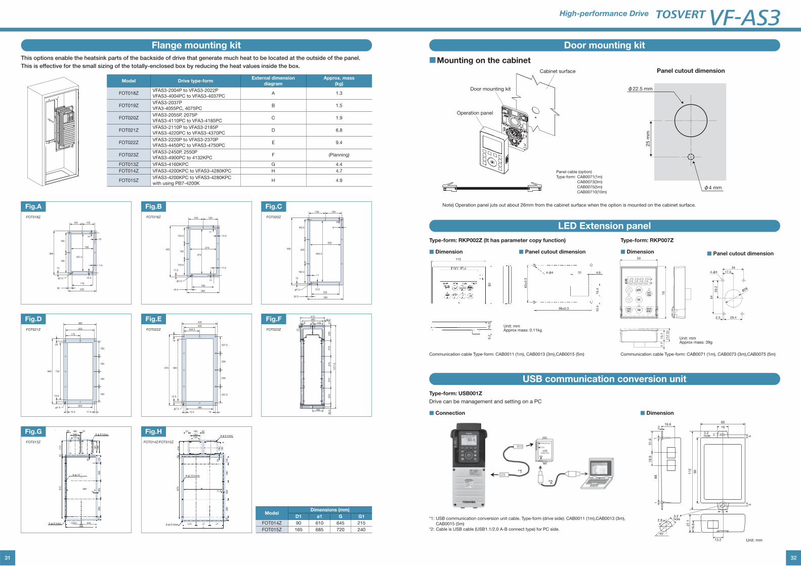
31
Flange mounting kit
This options enable the heatsink parts of the backside of drive that generate much heat to be located at the outside of the panel.
This is effective for the small sizing of the totally-enclosed box by reducing the heat values inside the box.
Model Drive type-formExternal dimension
diagram
Approx. mass
(kg)
FOT018ZVFAS3-2004P to VFAS3-2022P
VFAS3-4004PC to VFAS3-4037PCA 1.3
FOT019ZVFAS3-2037P
VFA3-4055PC, 4075PCB 1.5
FOT020ZVFAS3-2055P, 2075P
VFAS3-4110PC to VFA3-4185PCC 1.9
FOT021ZVFAS3-2110P to VFAS3-2185P
VFAS3-4220PC to VFAS3-4370PCD 6.8
FOT022ZVFAS3-2220P to VFAS3-2370P
VFAS3-4450PC to VFAS3-4750PCE 9.4
FOT023ZVFAS3-2450P, 2550P
VFAS3-4900PC to 4132KPCF (Planning)
FOT013Z VFAS3-4160KPC G 4.4
FOT014Z VFAS3-4200KPC to VFAS3-4280KPC H 4.7
FOT015ZVFAS3-4200KPC to VFAS3-4280KPC
with using PB7-4200KH 4.9
23530
105 105
φ7.5
165
165
360
15
175
10
7.5
12.5
10
190
307.5
Fig.A
175
350
325
385
800 733
190
190
190
190
20
13.5
12.5 17.5
φ7.5
Fig.D
19
51
80
45 180 10
150120
15
(245) 245
460
490
21
05
09
70
28
06
02
80
28
01
20
20
8-φ 10
6-φ 8 holes
8-φ 8 holesFig.G
120 120
133.5
130
133.5
420
11.5
26542.5
180
φ7.5
17.5
12.5
11
11
215
375
Fig.B
202.5
405
380
435
975 920
237.5
235
235
237.5
15
12.5
12.5 15
φ7.5
Fig.E145
26.5
413
180
21
1417.5
360
56.5
270
270
270
270
239
70
15
9Fig.F
D1 190 50
160130
17.5
(J1) J1
al
J
J1
21
05
09
70
28
06
02
80
28
01
20
20
19
5
18
0
8-φ 8 holes
8-φ 8 holes
8-φ 10 holes
Fig.H
135 135
162.5
200
162.5
555
15
12.5
32.5 295
φ7.5230
502.5
252
11
9
10
Fig.C
ModelDimensions (mm)
D1 a1 G G1
FOT014Z 90 610 645 215
FOT015Z 165 685 720 240
FOT023ZFOT022Z
FOT020ZFOT019Z
FOT014Z/FOT015ZFOT013Z
FOT021Z
FOT018Z
32
High-performance Drive
Door mounting kit
Cabinet surface
Operation panel
φ22.5 mm
φ4 mm
25 m
m
Panel cutout dimension
Door mounting kit
LED Extension panel
USB communication conversion unit
■Mounting on the cabinet
Panel cable (option)
Type-form: CAB0071(1m)
CAB0073(3m)
CAB0075(5m)
CAB00710(10m)
Note) Operation panel juts out about 26mm from the cabinet surface when the option is mounted on the cabinet surface.
80
115
16.2
9.2
4-φ4 31 4.6
16.4
10.498±0.3
63±
0.3
Type-form: RKP002Z (It has parameter copy function)
Type-form: USB001Z
Drive can be management and setting on a PC
Type-form: RKP007Z
Communication cable Type-form: CAB0011 (1m), CAB0013 (3m),CAB0015 (5m)
*1: USB communication conversion unit cable. Type-form (drive side): CAB0011 (1m),CAB0013 (3m),
CAB0015 (5m)
*2: Cable is USB cable (USB1.1/2.0 A-B connect type) for PC side.
Communication cable Type-form: CAB0071 (1m), CAB0073 (3m),CAB0075 (5m)
■ Panel cutout dimension ■ Panel cutout dimension■ Dimension ■ Dimension
■ Dimension
60
5
3.2 hole
1
219.6
88
1
19.9
31.6
90
112
16
5
9
13.2
19.627.1
3.2 hole
45°
2.8
Unit: mmApprox mass: 0.11kg
Unit: mm
■ Connection
50
4-φ4
φ28
54
29.2
34
17.5
29.42.3
70
(17.5)
15.1
7.7
Unit: mmApprox mass: 39g
*1
*2
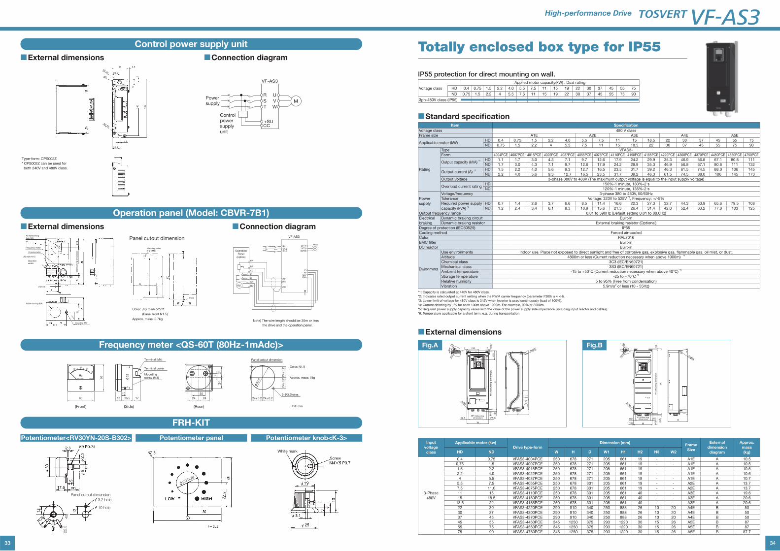
33
Control power supply unit
Operation panel (Model: CBVR-7B1)
Frequency meter <QS-60T (80Hz-1mAdc)>
FRH-KIT
■External dimensions
■External dimensions
■Connection diagram
■Connection diagram
Type-form: CPS002Z
* CPS002Z can be used for
both 240V and 480V class.
41 3.5
20.5
R2.25
φ8 5
5
140
150
4.5
20.5
R2.25
Control powersupply unit
R
S
T
+SU
VF-AS3
CC
U
V
W
MPowersupply
Panel cutout dimension
Color: JIS mark 5Y7/1
(Panel front N1.5)
Approx. mass: 0.7kg
90(M
ounting
dim
ensio
n)
φ5 hole
R2.5(Mounting
hole M4)
R5
Frequency meter
Potentiometer
JIS mark N1.5
Operation
switch
Mounting holes
2-φ4(M3)
Panel
Rubber bushing(φ34)
Grounding (M5)Note) The wire length should be 30m or less
the drive and the operation panel.
Operation
Panel
(option)
PP
RR
CC
F
R
CC
FM
Forward
Reverse
R/L1
PPRR
CC
FMCC
RF
U/T1V/T2
W/T3M
Motor
VF-AS3
FM
S/L2T/L3
(Rear)(Front) (Side)
24±
0.2
24±
0.2
24±0.224±0.2
Color: N1.5
Approx. mass: 75g
Unit: mm
Panel cutout dimension
φ53.5
2-φ3.5holes
24
9
24
24
30
24
80
80Hz-1mAdc QS60T
Hz
2040 60
0
60
60 13
10
25.5 17
φ52
Terminal (M4)
Terminal cover
Mounting screw (M3)
22.5
45
Panel cutout dimension3.2 hole
10 hole
φ20 hole
Screw
White mark
Potentiometer<RV30YN-20S-B302> Potentiometer panel Potentiometer knob<K-3>
34
High-performance Drive
Totally enclosed box type for IP55
IP55 protection for direct mounting on wall.
Voltage class
Applied motor capacity(kW) : Dual rating
HD 0.4 0.75 1.5 2.2 4.0 5.5 7.5 11 15 19 22 30 37 45 55 75
ND 0.75 1.5 2.2 4 5.5 7.5 11 15 19 22 30 37 45 55 75 90
3ph-480V class (IP55)
■Standard specificationItem Specification
Voltage class 480 V class
Frame size A1E A2E A3E A4E A5E
Applicable motor (kW)HD 0.4 0.75 1.5 2.2 4.0 5.5 7.5 11 15 18.5 22 30 37 45 55 75
ND 0.75 1.5 2.2 4 5.5 7.5 11 15 18.5 22 30 37 45 55 75 90
Rating
Type VFAS3-
Form 4004PCE 4007PCE 4015PCE 4022PCE 4037PCE 4055PCE 4075PCE 4110PCE 4150PCE 4185PCE 4220PCE 4300PCE 4370PCE 4450PCE 4550PCE 4750PCE
Output capacity (kVA) *1 HD 1.1 1.7 3.0 4.3 7.1 9.7 12.6 17.9 24.2 29.9 35.3 46.9 56.8 67.1 80.8 111
ND 1.7 3.0 4.3 7.1 9.7 12.6 17.9 24.2 29.9 35.3 46.9 56.8 67.1 80.8 111 132
Output current (A) *2 HD 1.5 2.2 4.0 5.6 9.3 12.7 16.5 23.5 31.7 39.2 46.3 61.5 74.5 88.0 106 145
ND 2.2 4.0 5.6 9.3 12.7 16.5 23.5 31.7 39.2 46.3 61.5 74.5 88.0 106 145 173
Output voltage 3-phase 380V to 480V (The maximum output voltage is equal to the input supply voltage)
Overload current ratingHD 150%-1 minute, 180%-2 s
ND 120%-1 minute, 135%-2 s
Power
supply
Voltage/frequency 3-phase 380 to 480V, 50/60Hz
Tolerance Voltage: 323V to 528V *3, Frequency: +/-5%
Required power supply
capacity (kVA) *4
HD 0.7 1.4 2.6 3.7 6.6 8.5 11.4 16.6 22.3 27.3 32.7 44.3 53.9 65.6 79.5 108
ND 1.2 2.4 3.4 6.1 8.3 10.9 15.6 21.3 26.4 31.4 42.0 52.4 63.2 77.0 103 125
Output frequency range 0.01 to 590Hz (Default setting 0.01 to 80.0Hz)
Electrical
braking
Dynamic braking circuit Built-in
Dynamic braking resistor External braking resistor (Optional)
Degree of protection (IEC60529) IP55
Cooling method Forced air-cooled
Color RAL7016
EMC filter Built-in
DC reactor Built-in
Environments
Use environments Indoor use. Place not exposed to direct sunlight and free of corrosive gas, explosive gas, flammable gas, oil mist, or dust.
Altitude 4800m or less (Current reduction necessary when above 1000m) *4
Chemical class 3C3 (IEC/EN60721)
Mechanical class 3S3 (IEC/EN60721)
Ambient temperature -15 to +50°C (Current reduction necessary when above 40°C) *5
Storage temperature -25 to +70°C *6
Relative humidity 5 to 95% (Free from condensation)
Vibration 5.9m/s2 or less (10 - 55Hz)
*1: Capacity is calculated at 440V for 480V class.
*2: Indicates rated output current setting when the PWM carrier frequency (parameter F300) is 4 kHz.
*3: Lower limit of voltage for 480V class is 342V when inverter is used continuously (load of 100%).
*4: Current derating by 1% for each 100m above 1000m. For example, 90% at 2000m.
*5: Required power supply capacity varies with the value of the power supply side impedance (including input reactor and cables).
*6: Temperature applicable for a short term. e.g. during transportation
■External dimensions
Input
voltage
class
Applicable motor (kw)Drive type-form
Dimension (mm)Frame
Size
External
dimension
diagram
Approx.
mass
(kg)HD ND W H D W1 H1 H2 H3 W2
3-Phase
480V
0.4 0.75 VFAS3-4004PCE 250 678 271 205 661 19 - - A1E A 10.5
0,75 1.5 VFAS3-4007PCE 250 678 271 205 661 19 - - A1E A 10.5
1.5 2.2 VFAS3-4015PCE 250 678 271 205 661 19 - - A1E A 10.5
2.2 4.0 VFAS3-4022PCE 250 678 271 205 661 19 - - A1E A 10.6
4 5.5 VFAS3-4037PCE 250 678 271 205 661 19 - - A1E A 10.7
5.5 7.5 VFAS3-4055PCE 250 678 301 205 661 19 - - A2E A 13.7
7.5 11.0 VFAS3-4075PCE 250 678 301 205 661 19 - - A2E A 13.7
11 15 VFAS3-4110PCE 250 678 301 205 661 40 - - A3E A 19.6
15 18.5 VFAS3-4150PCE 250 678 301 205 661 40 - - A3E A 20.6
18.5 22 VFAS3-4185PCE 250 678 301 205 661 40 - - A3E A 20.6
22 30 VFAS3-4220PCE 290 910 340 250 888 26 10 20 A4E B 50
30 37 VFAS3-4300PCE 290 910 340 250 888 26 10 20 A4E B 50
37 45 VFAS3-4370PCE 290 910 340 250 888 26 10 20 A4E B 50
45 55 VFAS3-4450PCE 345 1250 375 293 1220 30 15 26 A5E B 87
55 75 VFAS3-4550PCE 345 1250 375 293 1220 30 15 26 A5E B 87
75 90 VFAS3-4750PCE 345 1250 375 293 1220 30 15 26 A5E B 87.7
4xφ201357 7 10
.51
03
H
H1
(M
ou
ntin
g d
imen
sio
n)
D
17
(22.5)22.5W1 (Mounting
dimension)
W
4xR3
(6.5
)
H2
R3
R7
9
Fig.A
W2 (W2)
(17) W
W1 (Mounting dimension)
(H3
) (H2
)
D
2xR5.7
H3
H
H1 (M
ounting
dim
ensio
n)
4xφ36
R5.7
R12
17
Fig.B
Global Sales Department Motor Drive Division 580, Horikawa-cho, Saiwai-ku, Kawasaki, Kanagawa 212-0013, JapanTel : +81-44-520-0828Fax : +81-44-520-0508
Toshiba Industrial Products and Systems Corporation
AB16-05
Printed in Japan
For users of the products : Our variable speed drives are designed to control the speeds of three-phase motors for general industry.
For further information, please contact your nearest Toshiba Representative or International Operations-Producer Goods. The information in this brochure is subject to
change without notice.
Precautions
* Please read the instruction manual before installing or operating the drive unit.
* This product is intended for general purpose uses in industrial application. It cannot be used applications where may cause big impact
on public uses, such as power plant and railway, and equipment which endanger human life or injury, such as nuclear power control,
aviation, space flight control, traffic, safety device, amusement, or medical.
It may be considerable whether to apply, under the special condition or an application where strict quality control may not be required.
Please contact our headquarters, branch, or local offices printed on the front and back covers of this catalogue.
* When exporting Toshiba variable speed drive separately or combined with your equipment, please be sure to satisfy the objective
conditions and inform conditions listed in the export control policies, so called Catch All restrictions, which are set by the Ministry of
Economy, Trade and Industry of Japan, and the appropriate export procedures must also be taken.
* Please use our product in applications where do not cause serious accidents or damages even if product is failure, or please use in
environment where safety equipment is applicable or a backup circuit device is provided outside the system.
* Please do not use our product for any load other than three-phase motors.
* None of Toshiba, its subsidiaries, affiliates or agents, shall be liable for any physical damages, including, without limitation, malfunction,
anomaly, breakdown or any other problem that may occur to any apparatus in which the Toshiba variable speed drive is incorporated
or to any equipment that is used in combination with the Toshiba variable speed drive. Nor shall Toshiba, its subsidiaries, affiliates or
agents be liable for any compensatory damages resulting from such utilization, including compensation for special, indirect, incidental,
consequential, punitive or exemplary damages, or for loss of profit, income or data, even if the user has been advised or apprised of
the likelihood of the occurrence of such loss or damages.