Embed Size (px)
Citation preview

Variable speed drivesAltivar 71
05CatalogueMarch
For 3-phase asynchronous motors from 0.37 to 500 kW
Elmatik AS, Türi 9, 11314 Tallinn Estonia tel. +372 650 3875 tel. +372 650 3876 fax +372 655 8019 e-mail: [email protected]

Elmatik AS, Türi 9, 11314 Tallinn Estonia tel. +372 650 3875 tel. +372 650 3876 fax +372 655 8019 e-mail: [email protected]

1
Contents Variable speed drives for asynchronous motorsAltivar 71
Selection guide . . . . . . . . . . . . . . . . . . . . . . . . . . . . . . . . . . . . . . . . . . . . . . .page 2
b Presentation . . . . . . . . . . . . . . . . . . . . . . . . . . . . . . . . . . . . . . . . . . . . . . . . page 2
b Variable speed drives
v Characteristics . . . . . . . . . . . . . . . . . . . . . . . . . . . . . . . . . . . . . . . . . . . . . page 8
v Operation . . . . . . . . . . . . . . . . . . . . . . . . . . . . . . . . . . . . . . . . . . . . . . . . page 14
v References . . . . . . . . . . . . . . . . . . . . . . . . . . . . . . . . . . . . . . . . . . . . . . page 18
b Options
v accessories . . . . . . . . . . . . . . . . . . . . . . . . . . . . . . . . . . . . . . . . . . . . . . page 20
v dialogue . . . . . . . . . . . . . . . . . . . . . . . . . . . . . . . . . . . . . . . . . . . . . . . . . page 26
v encoder interface cards . . . . . . . . . . . . . . . . . . . . . . . . . . . . . . . . . . . . . page 29
v I/O extension cards . . . . . . . . . . . . . . . . . . . . . . . . . . . . . . . . . . . . . . . . page 31
v "Controller Inside" programmable card . . . . . . . . . . . . . . . . . . . . . . . . . page 39
v communication buses and networks . . . . . . . . . . . . . . . . . . . . . . . . . . . page 46
v resistance braking units . . . . . . . . . . . . . . . . . . . . . . . . . . . . . . . . . . . . page 49
v braking resistors . . . . . . . . . . . . . . . . . . . . . . . . . . . . . . . . . . . . . . . . . . page 51
v hoist resistors. . . . . . . . . . . . . . . . . . . . . . . . . . . . . . . . . . . . . . . . . . . . . page 53
v network braking units. . . . . . . . . . . . . . . . . . . . . . . . . . . . . . . . . . . . . . . page 63
b Reduction of current harmonics
v DC chokes . . . . . . . . . . . . . . . . . . . . . . . . . . . . . . . . . . . . . . . . . . . . . . . page 69
v line chokes. . . . . . . . . . . . . . . . . . . . . . . . . . . . . . . . . . . . . . . . . . . . . . . page 72
v passive filters . . . . . . . . . . . . . . . . . . . . . . . . . . . . . . . . . . . . . . . . . . . . . page 74
v additional EMC input filters . . . . . . . . . . . . . . . . . . . . . . . . . . . . . . . . . . page 78
b Output filters
v motor chokes . . . . . . . . . . . . . . . . . . . . . . . . . . . . . . . . . . . . . . . . . . . . . page 82
v sinus filters. . . . . . . . . . . . . . . . . . . . . . . . . . . . . . . . . . . . . . . . . . . . . . . page 85
b Combinations of variable speed drives and options . . . . . . . . . . . . . . page 86
b Dimensions . . . . . . . . . . . . . . . . . . . . . . . . . . . . . . . . . . . . . . . . . . . . . . . page 90
b Schemes. . . . . . . . . . . . . . . . . . . . . . . . . . . . . . . . . . . . . . . . . . . . . . . . . page 112
b Motor starters . . . . . . . . . . . . . . . . . . . . . . . . . . . . . . . . . . . . . . . . . . . . page 128
b Mounting recommendations . . . . . . . . . . . . . . . . . . . . . . . . . . . . . . . . page 132
b Combinations of functions and applications . . . . . . . . . . . . . . . . . . . page 140
b Functions . . . . . . . . . . . . . . . . . . . . . . . . . . . . . . . . . . . . . . . . . . . . . . . . page 142
b Compatibilty table for functions . . . . . . . . . . . . . . . . . . . . . . . . . . . . . page 174
b PowerSuite software workshop . . . . . . . . . . . . . . . . . . . . . . . . . . . . . . page 179
b Ethernet TCP/IP network. . . . . . . . . . . . . . . . . . . . . . . . . . . . . . . . . . . . page 184
b Communication via Fipio bus . . . . . . . . . . . . . . . . . . . . . . . . . . . . . . . page 188
b Communication via Modbus bus . . . . . . . . . . . . . . . . . . . . . . . . . . . . . page 191
b Communication via Modbus Plus bus. . . . . . . . . . . . . . . . . . . . . . . . . page 196
b Communication via Uni-Telway bus . . . . . . . . . . . . . . . . . . . . . . . . . . page 199
b Communication gateways LUF P . . . . . . . . . . . . . . . . . . . . . . . . . . . . . page 201
b Communication gateway LA9 P307 . . . . . . . . . . . . . . . . . . . . . . . . . . . page 203
b Schneider Electric worldwide. . . . . . . . . . . . . . . . . . . . . . . . . . . . . . . . page 204
b Product reference index . . . . . . . . . . . . . . . . . . . . . . . . . . . . . . . . . . . . page 210
Elmatik AS, Türi 9, 11314 Tallinn Estonia tel. +372 650 3875 tel. +372 650 3876 fax +372 655 8019 e-mail: [email protected]

2
Selection guide 1 Variable speed drivesfor asynchronous motors 1
Applications Speed control for asynchronous motorsApplication area Industry
Type of machine Simple machines
Power range for 50…60 Hz supply (kW) 0.18…2.2 0.18…15Single phase 100…120 V (kW) 0.18…0.75 –
Single phase 200…240 V (kW) 0.18…2.2 0.18…2.2Three phase 200…230 V (kW) 0.18…2.2 –
Three phase 200…240 V (kW) – 0.18…15
Three phase 380…460 V (kW) – –
Three phase 380…480 V (kW) – –Three phase 380…500 V (kW) – 0.37…15
Three phase 525…600 V (kW) – 0.75…15
Drive Output frequency 0.5…200 Hz 0.5…500 Hz
Type of control Asynchronous motor Sensorless flux vector control
Synchronous motor –
Transient overtorque 150…170% of the nominal motor torque 170…200% of the nominal motor torque
FunctionsNumber of functions 26 50Number of preset speeds 4 16
Number of I/O Analog inputs 1 3
Logic inputs 4 6Analog outputs – 1
Logic outputs 1 –
Relay outputs 1 2
Communication Embedded – Modbus and CANopen
Available as an option – Ethernet TCP/IP, DeviceNet, Fipio, Profibus DP
Cards (available as an option) – –
Standards and certification EN 50178, IEC/EN 61800-3EN 55011, EN 55022:class B and class A gr.1e, UL, CSA, NOM 117, C-Tick
EN 50178, IEC/EN 61800-3EN 55011, EN 55022: class A, class B with option carde, UL, C-Tick, N998
References ATV 11 ATV 31
Pages Please consult the “Soft starters and variable speed drives” catalogue
Elmatik AS, Türi 9, 11314 Tallinn Estonia tel. +372 650 3875 tel. +372 650 3876 fax +372 655 8019 e-mail: [email protected]

3
11
Building Industry
Pumps and fans Complex, modular machinesMachines requiring high-performance torque and accuracy at very low speed as well as high dynamicsHigh-power machines
0.75…315 0.37…500– –
– 0.37…5.5– –
– 0.37…75
0.75…315 –
– 0.75…500– –
– –
0.1…500 Hz 0…1000 Hz
Sensorless flux vector control Flux vector control with or without sensor, voltage/frequency ratio (2 or 5 pulses), ENA System
– Vector control without speed feedback
110% of nominal motor torque for 60 seconds
220% of nominal motor torque for 2 seconds, 170% for 60 seconds
44 > 1508 16
2…3 2…4
4…6 6…201…2 1…3
0…1 0…8
2 2…4
Modbus Modbus and CANopen
Ethernet TCP/IP, Fipio, Modbus Plus, INTERBUS, Profibus DP, AS-Interface, Uni-Telway, CANopen, DeviceNet, METASYS N2, Lonworks
Ethernet TCP/IP, Fipio, Modbus Plus, INTERBUS, Profibus DP, Modbus/Uni-Telway, DeviceNet
Pump switchingI/O extension cardsProgrammable "Controller Inside" card
Encoder interface cardsI/O extension cardsProgrammable "Controller Inside" card
EN 50178, IEC/EN 61800-3EN 55011 class AEN 55022 class Be, UL, N998
IEC/EN 61800-5-1, IEC/EN 61800-3 (environments 1 and 2, C1 to C3)EN 55011, EN 55022, IEC/EN 61000-4-2/4-3/4-4/4-5/4-6/4-11e, UL, CSA, DNV, C-Tick, NOM 117, GOST
ATV 38 ATV 71
Please consult the “Soft starters and variable speed drives” catalogue
18 and 19
Elmatik AS, Türi 9, 11314 Tallinn Estonia tel. +372 650 3875 tel. +372 650 3876 fax +372 655 8019 e-mail: [email protected]

4
Presentation 1 Variable speed drivesfor asynchronous motors 1
Altivar 71
The Altivar 71 range of variable speed drives is able to respond to the most exacting requirements thanks to its different types of motor control and numerous onboard functions. It is suitable for the most demanding drives:b Torque and speed accuracy at very low speeds, high dynamics with Flux Vector Control (with or without sensor)b Extended frequency range for high-speed motorsb Connection of special motors and drives in parallel thanks to the voltage/frequency ratiob Static speed accuracy and energy savings for synchronous motors in open loop modeb Smooth flexibility for unbalanced machines with the ENA System (Energy Adaptation System)
The functionality of the Altivar 71 drive boosts performance and increases a machine’s flexibility of use across multiple applications.
b Brake control adapted for translational, hoisting and slewing movementsb Load measurement using weight sensorb High-speed hoistingb Brake feedback managementb Limit switch management
b Very quick response times on transmission of a command: 2 ms (± 0.5 ms)b Reference via pulse train or differential analog inputb Control via the principal communication networksb Position control via limit switches with time optimization at low speedb Multiple parameter-settings via parameter set switching
b Up to 50 Hz of the bandwidthb Very quick response times on change of reference: 2 ms (± 0.5 ms)b Control via integrated CANopen busb Position control via limit switches
b High resolution of the digital speed reference (1/32000)b Speed accuracy assured by use of synchronous motor, irrespective of the loadb High bandwidthb Spooling functionb Connection to common DC bus
b Operation up to 1000 Hzb Fastest possible controlled stop on loss of line supplyb Control via integrated CANopen busb Protection of motor against overvoltages
b PID regulatorb High reference resolutionb Speed or torque controlb Connection to the principal communication networksb Separate control power supplyb Braking unit via re-injection to the line supplyb Connection to common DC bus
b Brake control adapted to suit passenger comfortb Processing of load measurement by weight sensorb Conformity of relays to lift safety standard EN 81-13-2-2-3b Connection to CANopen busb Control with integrity check of output contactorb Lift car clearance function
Applications
Hoisting Hoisting application
5325
37
Handling
Packing
Packing application
532
538
Textile machinery
Wood-working machinery
Process machinery
Process machinery application
532
539
Lifts
Characteristics:pages 8 to 13
References:pages 18 and 19
Dimensions:pages 90 to 111
Schemes:pages 112 to 127
Functions:pages 142 to 173
Elmatik AS, Türi 9, 11314 Tallinn Estonia tel. +372 650 3875 tel. +372 650 3876 fax +372 655 8019 e-mail: [email protected]

5
Presentation (continued) 1 Variable speed drivesfor asynchronous motors 1
Altivar 71
Comprehensive offer The Altivar 71 range of variable speed drives extends across a range of motor power ratings from 0.37 kW to 500 kW with three types of power supply: b 200…240 V single phase, from 0.37 kW to 5.5 kWb 200…240 V three phase, from 0.37 kW to 75 kWb 380…480 V three phase, from 0.75 kW to 500 kW
The Altivar 71 drive integrates the Modbus and CANopen protocols as standard as well as numerous functions.
These functions can be extended using communication, I/O and encoder interface option cards (see page 7).
The entire range conforms to international standards IEC/EN 61800-5-1, IEC/EN 61800-2, IEC/EN 61800-3, is e, UL, CSA, DNV, C-Tick, NOM 117 and GOST certified and has been developed to meet the directives regarding protection of the environment (RoHS, WEEE, etc).
The Altivar 71 can be inserted in an installation’s safety system. It integrates the “Power Removal” safety function which prohibits any accidental starting of the motor. This function complies with machine standard EN 954-1 category 3, the standard governing electrical installations IEC/EN 61508 SIL2 and the power drive systems standard IEC/EN 61800-5-2.
Electromagnetic compatibility EMCThe incorporation of EMC filters in ATV 71HpppM3 and ATV 71HpppN4 drives and the recognition of EMC requirements simplifies machine installation and provides an economical means of meeting e marking requirements.ATV 71HpppM3X drives are available without EMC filters. The filters are available as an option and can be installed by the user to reduce emission levels (see pages 76 to 79).
Other external options, such as braking resistors, network braking units and filters, are available to complement this offer (see page 7).
Installation The Altivar 71 drive has been designed to optimize the size of enclosures (floor-standing, wall-mounted, etc):b The power part, with IP 54 degree of protection, can be easily mounted outside the enclosure using the kit for flush-mounting in a dust and damp proof enclosure VW3 A9 5pp.This type of mounting can be used to limit the temperature rise inside the enclosure or to reduce the size of enclosure required (see page 21).b Ambient temperature inside the enclosure: v 50°C without deratingv Up to 60°C using the control card fan kit VW3 A9 4pp corresponding to the drive rating and, if necessary, by derating the output current (see page 20)b Mounting side-by-side (see pages 132 and 134)
The drive can also be wall-mounted in compliance with NEMA type 1 requirements using kit VW3 A9 2pp, for IP 21 protection or IP 31 using kit VW3 A9 1pp (see pages 22 and 23).
5327
26
ATV 71HC28N4, ATV 71HD37M3X, ATV 71HU22N4
5332
35
ATV 71HU75N4 flush-mounted
Characteristics:pages 8 to 13
References:pages 18 and 19
Dimensions:pages 90 to 111
Schemes:pages 112 to 127
Functions:pages 142 to 173
Elmatik AS, Türi 9, 11314 Tallinn Estonia tel. +372 650 3875 tel. +372 650 3876 fax +372 655 8019 e-mail: [email protected]

6
Presentation (continued) 1 Variable speed drivesfor asynchronous motors 1
Altivar 71
Dialogue tools The Altivar 71 drive 1 is supplied with a removable graphic display terminal 2 for remote operation:b The navigation button accesses the drop-down menus quickly and easily.b The graphic screen displays 8 lines of 24 characters of plain text.b The advanced functions on the display unit access the more complex drive functions.b The display screens, menus and parameters can all be customized for the user or the machine.b Online help screens are available.b Configurations can be stored and downloaded (four configuration files can be stored).b The drive can be connected to several other drives via a multidrop link.b It can be located remotely on an enclosure door with IP 54 or IP 65 degree of protection.b It is supplied with 6 languages installed as standard (English, French, German, Italian, Spanish and Chinese). Other languages can be loaded to the flash memory.
Up to 15 kW, the Altivar 71 drive can be controlled using an integrated 7-segment display terminal (see pages 18 and 19).
The PowerSuite software workshop 3 can be used to configure, adjust and debug the Altivar 71 in just the same way as all other Telemecanique drives and starters. It can be used via a direct connection, Ethernet, modem or a Bluetooth® wireless connection.
Quick programmingMacro-configurationThe Altivar 71 offers quick and easy programming using macro-configurations corresponding to different applications or uses: start-stop, material handling, hoisting, general use, connection to communication networks, PID regulator, master/slave. Each of these configurations is still fully modifiable.
“Simply start” menu The “Simply start” menu can be used to ensure the application operates correctly, obtain maximum motor performance and ensure motor protection.
The architecture, the hierarchical parameter structure and the direct access functions all serve to make programming quick and easy, even for the more complex functions.
Services The Altivar 71 has numerous built-in maintenance, monitoring and diagnostic functions:b Built-in drive test functions with diagnostic screen on the remote graphic display terminalb I/O mapsb Communication maps for the different portsb Oscilloscope function that can be viewed using the PowerSuite software workshopb Management of the drive installed base via processors with flash memory.b Remote use of these functions by connecting the drive to a modem via the Modbus portb Identification of all the drive’s component parts as well as the software versionsb Fault logs with display of the value of up to 16 variables on occurrence of a faultb Display terminal languages loaded in the flash memoryb A message of up to 5 lines of 24 characters can be stored in the drive.
1
2
3
3
M. handling
50Hz IEC
2.2kW
400V
:
:
:
:
: 2 wire
+50.00HzTerm1.1 SIMPLY START
Standard mot. Freq.
5.4A
Macro-configuration
Rated motor power
Rated motor volt.
<< >> QuickCode
RUN
2/3 wire control
522
151
“Simply start” menu
+50.00HzTermFAULT HISTORY
External FLT
0.0A
Overcurrent
Overvoltage
Undervoltage
QuickHelp
SCF1
Short circuit
5335
23
Fault log
+50.00HzTermMOTOR SHORT CIRCUIT
0.0A
Perform the diagnostic test.
Quick
SCF1
Check the connection cables
and the motor insulation.
5221
62
Troubleshooting screen
Characteristics:pages 8 to 13
References:pages 18 and 19
Dimensions:pages 90 to 111
Schemes:pages 112 to 127
Functions:pages 142 to 173
Elmatik AS, Türi 9, 11314 Tallinn Estonia tel. +372 650 3875 tel. +372 650 3876 fax +372 655 8019 e-mail: [email protected]

7
Presentation (continued) 1 Variable speed drivesfor asynchronous motors 1
Altivar 71
The Altivar 71 drive 1 can integrate a maximum of three option cards simultaneously, of which:b 2 can be selected from among the following (1):v I/O extension cards 2 (see pages 30 and 31)v communication cards 2 (Ethernet TCP/IP, Modbus/Uni-Telway, Fipio, Modbus Plus, Profibus DP, DeviceNet, INTERBUS, etc) (see pages 40 to 47)v programmable “Controller Inside” card 2. This is used to adapt the drive to specific applications quickly and progressively, by decentralizing the control system functions (programming in IEC 61131-3 compliant languages) (see pages 32 to 39).b 1 can be an encoder interface card 3 (with RS 422 compatible differential outputs, open collector outputs, push-pull outputs) (see pages 28 and 29).
External options can be associated with the Altivar 71:b Braking units and resistors (standard or hoist-specific) (see pages 48 to 61)b Networked braking units (see pages 62 to 65)b Line chokes, DC chokes and passive filters, to reduce harmonic currents (see pages 66 to 75)b Motor chokes and sinus filters for long cable runs or to remove the need for shielding (see pages 80 to 85)b Additional EMC input filters (see pages 76 to 79)
Note: please refer to the compatibility summary tables to determine which options are available for individual drives (see pages 86 to 89).
The Altivar 71 integrates a combined Modbus or CANopen port for quick, accurate motion control, adjustment, supervision and configuration. A second port is available for connecting a Magelis terminal for machine dialogue.
The drive can also be connected to other communication networks using the communication option cards (see pages 40 to 47).
The control part can be powered separately, thus allowing communication (monitoring, diagnostics) to be maintained even if the power part supply fails.
The programmable “Controller Inside” card transforms the drive into an automation island:b The card integrates its own I/O; it can also manage those of the drive and an I/O extension card.b It contains onboard application programs developed in IEC 61131-3 compliant languages, which reduce the control system response time.b Its CANopen master port enables control of other drives and dialogue with I/O modules and sensors.
(1) The Altivar 71 cannot support more than one option card with the same reference. Please refer to the compatibility tables summarizing the possible combinations for drives, options and accessories on pages 86 to 89.
Options
1
2 2
3
Integration into control systems
Example of a drive equipped with a communication card and a programmable “Controller Inside” card
Premium ATV 71Magelis XBT
I/O STBATV 31
I/O OTB Sensor
ModbusEthernet
CANopen master
Characteristics:pages 8 to 13
References:pages 18 and 19
Dimensions:pages 90 to 111
Schemes:pages 112 to 127
Functions:pages 142 to 173
Elmatik AS, Türi 9, 11314 Tallinn Estonia tel. +372 650 3875 tel. +372 650 3876 fax +372 655 8019 e-mail: [email protected]

8
Characteristics 1 Variable speed drivesfor asynchronous motors 1
Altivar 71
Environmental characteristicsConformity to standards Altivar 71 drives have been developed to conform to the strictest international
standards and the recommendations relating to electrical industrial control devices (IEC, EN), in particular: low voltage, IEC/EN 61800-5-1, IEC/EN 61800-3 (conducted and radiated EMC immunity and emissions).
EMC immunity IEC/EN 61800-3, environments 1 and 2IEC/EN 61000-4-2 level 3IEC/EN 61000-4-3 level 3IEC/EN 61000-4-4 level 4IEC/EN 61000-4-5 level 3IEC/EN 61000-4-6 level 3IEC/EN 61000-4-11 (1)
Conducted and radiated EMC emissions for drives
IEC/EN 61800-3, environments 1 and 2, categories C1, C2, C3ATV 71H037M3…HU15M3ATV 71H075N4…HU40N4
EN 55011 class A group 1, IEC/EN 61800-3 category C2With additional EMC filter (2):b EN 55011 class B group 1, IEC/EN 61800-3 category C1
ATV 71HU22M3…HU75M3ATV 71HU55N4…HC50N4
EN 55011 class A group 2, IEC/EN 61800-3 category C3With additional EMC filter (2):b EN 55011 class A group 1, IEC/EN 61800-3 category C2b EN 55011 class B group 1, IEC/EN 61800-3 category C1
ATV 71HpppM3X With additional EMC filter (2):b EN 55011 class A group 1, IEC/EN 61800-3 category C2b EN 55011 class B group 1, IEC/EN 61800-3 category C1
e marking The drives are marked e in accordance with the European low voltage (73/23/EEC and 93/68/EEC) and EMC (89/336/EEC) directives.
Product certifications UL, CSA, DNV, C-Tick, NOM 117 and GOSTDegree of protection IEC/EN 61800-5-1, IEC/EN 60529
ATV 71HpppM3ATV 71HD11M3X…HD45M3XATV 71H075N4…HD75N4
IP 21 and IP 41 on upper partIP 20 without cover plate on upper part of coverIP 21 with accessory VW3 A9 1pp, NEMA type 1 with accessory VW3 A9 2pp, see pages 22 and 23
ATV 71HD55M3X, HD75M3XATV 71HD90N4…HC50N4
IP 00, IP 41 on the upper part and IP 30 on the front panel and side parts.IP 31 with accessory VW3 A9 1pp, NEMA type 1 with accessory VW3 A9 2pp, see pages 22 and 23
Vibration resistance ATV 71HpppM3ATV 71HD11M3X…HD45M3XATV 71H075N4…HD75N4
1.5 mm peak to peak from 3…13 Hz, 1 gn from 13…200 Hz, conforming toIEC/EN 60068-2-6
ATV 71HD55M3X, HD75M3XATV 71HD90N4…HC50N4
1.5 mm peak to peak from 3…10 Hz, 0.6 gn from 10…200 Hz, conforming toIEC/EN 60068-2-6
Shock resistance ATV 71HpppM3ATV 71HD11M3X…HD45M3XATV 71H075N4…HD75N4
15 gn for 11 ms conforming to IEC/EN 60068-2-27
ATV 71HD55M3X, HD75M3XATV 71HD90N4…HC13N4
7 gn for 11 ms conforming to IEC/EN 60068-2-27
ATV 71HC16N4…HC50N4 4 gn for 11 ms conforming to IEC/EN 60068-2-27Maximum ambient pollution ATV 71HpppM3
ATV 71HD11M3X, HD15M3XATV 71H075N4…HD18N4
Degree 2 conforming to IEC/EN 61800-5-1
ATV 71HD18M3X…HD75M3XATV 71HD22N4…HC50N4
Degree 3 conforming to IEC/EN 61800-5-1
Environmental conditions ATV 71HpppM3, HpppM3X,ATV 71HpppN4
IEC 60721-3-3 classes 3C1 and 3S2
ATV 71HpppM3S337,ATV 71HpppM3X337,ATV 71H075N4S337…HD75N4S337,ATV 71HD90N4…HC50N4
IEC 60721-3-3 class 3C2
Relative humidity 5…95% without condensation or dripping water conforming to IEC 60068-2-3Ambient air temperaturearound the device
Operation °C - 10…+ 50 without deratingUp to 60°C with derating and with the control card fan kit VW3 A9 4pp corresponding to the drive rating (see derating curves on pages 133 and 135 to 137)
Storage °C - 25…+ 70Maximum operating altitude m 1000 without derating
1000…3000 derating the current by 1% per additional 100 m. Limited to 2000 m for the “Corner Grounded” distribution network
Operating positionMaximum permanent angle in relation to the normal vertical mounting position
(1) Drive behaviour according to the drive configurations(see pages 159, 162, 163, 171 and 172).
(2) See table on page 76 to check permitted cable lengths.
10˚ 10˚
Presentation:pages 4 to 6
References:pages 18 and 19
Dimensions:pages 90 to 111
Schemes:pages 112 to 127
Functions:pages 142 to 173
Elmatik AS, Türi 9, 11314 Tallinn Estonia tel. +372 650 3875 tel. +372 650 3876 fax +372 655 8019 e-mail: [email protected]
9
Characteristics (continued) 1 Variable speed drivesfor asynchronous motors 1
Altivar 71
Drive characteristicsOutput frequency range ATV 71HpppM3
ATV 71HD11M3X…HD37M3XATV 71H075N4…HD37N4
Hz 10…1000
ATV 71HD45M3X…HD75M3XATV 71HD45N4…HC50N4
Hz 10…500
Configurable switching frequency
kHz Adjustable during operation from 1…8, 2.5…8 or from 1…16 according to ratingATV 71HpppM3ATV 71HD11M3X, HD15M3XATV 71H075N4…HD30N4
kHz 4 without derating in continuous operationAbove this frequency, see derating curves on pages 133 and 135 to 137
ATV 71HD18M3X…HD75M3XATV 71HD37N4…HC50N4
kHz 2.5 without derating in continuous operation.Above this frequency, see derating curves on pages 133 and 135 to 137
Speed range 1…1000 in closed loop mode with encoder feedback1…100 in open loop mode
Speed accuracy For a torque variation of 0.2 Tn to Tn
± 0.01% of nominal speed, in closed loop mode with incremental encoder feedback± 10% of nominal slip, without speed feedback
Torque accuracy ± 5% in closed loop mode± 15% in open loop mode
Transient overtorque 170% of the nominal motor torque (typical value at ± 10%) for 60 s220% of the nominal motor torque (typical value at ± 10%) for 2 s
Braking torque 30% of motor nominal torque without braking resistor (typical value)Up to 150% with optional braking resistor, see pages 51 and 53
Maximum transient current 150% of the nominal drive current for 60 s (typical value)165% of the nominal drive current for 2 s (typical value)
Continuous torque at 0 Hz ATV 71H037M3…HD45M3XATV 71H075N4…HD75N4
The Altivar 71 drive can continuously supply the peak value of the drive nominal current
ATV 71HD55M3X, HD75M3XATV 71HD90N4…HC50N4
The Altivar 71 drive can continuously supply 80% of the peak value of the drive nominal current
Motor control profile Asynchronous motor Flux Vector Control (FVC) with sensor (current vector)Sensorless Flux Vector Control (FVC) (voltage or current vector)Voltage/frequency ratio (2 or 5 points) ENA (Energy Adaptation) System for unbalanced loads
Synchronous motor Vector control without speed feedback
Frequency loop PI regulator with adjustable structure for a speed response adapted to the machine (accuracy, speed)
Slip compensation Automatic whatever the load. Can be suppressed or adjustedNot available in voltage/frequency ratio
Electrical power characteristicsPower supply Voltage V 200 - 15%...240 + 10% single phase for ATV 71H075M3...HU75M3
200 - 15%...240 + 10% 3-phase for ATV 71HpppM3 and ATV 71HpppM3X380 - 15%...480 + 10% 3-phase for ATV 71HpppN4
Frequency Hz 50 - 5%...60 + 5%Signalling 1 red LED: LED lit indicates the presence of drive voltage
Output voltage Maximum 3-phase voltage equal to line supply voltage
Drive noise level Conforming to directive 86-188/EEC
ATV 71H037M3…HU15M3ATV 71H075N4…HU22N4
dBA 43
ATV 71HU22M3…HU40M3ATV 71H075N4…HU40N4
dBA 54.5
ATV 71HU55M3ATV 71HU55N4, HU75N4
dBA 55.6
ATV 71HU75M3ATV 71HD11N4
dBA 57.4
ATV 71HD11M3X, HD15M3XATV 71HD15N4, HD18N4
dBA 60.2
ATV 71HD18M3X, HD22M3XATV 71HD22N4
dBA 59.9
ATV 71HD30M3X…HD45M3X, ATV 71HD30N4, HD37N4
dBA 64
ATV 71HD45N4…HD75N4 dBA 63.7
ATV 71HD55M3XATV 71HD90N4
dBA 60.5
ATV 71HD75M3XATV 71HC11N4
dBA 69.5
ATV 71HC13N4, HC16N4 dBA 66ATV 71HC20N4…HC28N4 dBA 68
ATV 71HC31N4, HC40N4 dBA 70
ATV 71HC50N4 dBA 71Electrical isolation Between power and control (inputs, outputs, power supplies)
Presentation:pages 4 to 6
References:pages 18 and 19
Dimensions:pages 90 to 111
Schemes:pages 112 to 127
Functions:pages 142 to 173
Elmatik AS, Türi 9, 11314 Tallinn Estonia tel. +372 650 3875 tel. +372 650 3876 fax +372 655 8019 e-mail: [email protected]

10
Characteristics (continued) 1 Variable speed drivesfor asynchronous motors 1
Altivar 71
Connection cable characteristicsType of cable for Mounting in an enclosure Single-strand IEC cable, ambient temperature 45°C,
copper 90°C XLPE/EPR or copper 70°C PVCMounting in an enclosurewith an IP 21 or IP 31 kit
3-strand IEC cable, ambient temperature 40°C, copper 70°C PVC
Mounting in an enclosurewith NEMA type 1 kit
3-strand UL 508 cable except for choke (2-strand UL 508 cable),ambient temperature 40°C, copper 75°C PVC
Connection characteristics (terminals for the power supply, the motor, and the DC bus)Drive terminals L1/R, L2/S, L3/T U/T1, V/T2, W/T3 PC/-, PO, PA/+
Maximum connection capacity and tightening torque
ATV 71H037M3…HU40M3ATV 71H075N4…HU40N4
5 mm2, AWG 101.3 Nm
ATV 71HU55M3ATV 71HU55N4, HU75N4
8 mm2, AWG 81.3 Nm
ATV 71HU75M3ATV 71HD11N4
20 mm2, AWG 42.5 Nm
ATV 71HD11M3X, HD15M3XATV 71HD15N4, HD18N4
25 mm2, AWG 34.4 Nm
ATV 71HD18M3X, HD22M3XATV 71HD22N4
4 x 35 mm2, 3 x AWG 22.5 Nm
ATV 71HD30N4, HD37N4 4 x 50 mm2, 3 x AWG 1/02.5 Nm
ATV 71HD30M3X 4 x 70 mm2, 3 x AWG 2/02.5 Nm
ATV 71HD37M3X 4 x 95 mm2, 3 x AWG 4/02.5 Nm
ATV 71HD45M3X 4 x 120 mm2, 3 x 250 kcmil2.5 Nm
ATV 71HD45N4 4 x 70 mm2, 3 x AWG 2/02.5 Nm
ATV 71HD55N4 4 x 95 mm2, 3 x AWG 4/02.5 Nm
ATV 71HD75N4 4 x 120 mm2, 3 x 250 kcmil2.5 Nm
ATV 71HD55M3X 2 x (3 x 95 mm2), 2 x AWG 3/0–
2 x (3 x 70 mm2), 2 x AWG 1/0–
2 x 120 mm2, 2 x AWG 4/0–
ATV 71HD75M3X 2 x (3 x 95 mm2), 2 x AWG 3/0–
2 x (3 x 95 mm2), 2 x AWG 3/0–
2 x 120 mm2, 2 x AWG 4/0–
ATV 71HD90N4 2 x (3 x 70 mm2), 2 x AWG 1/0–
1 x (3 x 95 mm2), 2 x AWG 1/0–
2 x 95 mm2, 2 x AWG 3/0–
ATV 71HC11N4 2 x (3 x 95 mm2), 2 x AWG 3/0–
1 x (3 x 120 mm2), 2 x AWG 3/0–
2 x 120 mm2, 2 x AWG 4/0–
ATV 71HC13N4 2 x (3 x 95 mm2), 2 x AWG 3/0–
1 x (3 x 150 mm2), 2 x AWG 3/0–
2 x 120 mm2, 2 x AWG 4/0–
ATV 71HC16N4 2 x (3 x 120 mm2), 2 x AWG 4/0–
2 x (3 x 95 mm2), 2 x AWG 4/0–
2 x 150 mm2, 2 x 300 MCM–
ATV 71HC20N4 2 x (3 x 185 mm2), 2 x 300 MCM–
2 x (3 x 120 mm2), 2 x 300 MCM–
2 x 240 mm2, 3 x 250 MCM–
ATV 71HC25N4 Motor P 220 kW
2 x (3 x 185 mm2), 2 x 350 MCM–
2 x (3 x 150 mm2), 2 x 350 MCM–
3 x 150 mm2, 3 x 250 MCM–
Motor P 250 kW
3 x (3 x 150 mm2), 3 x 300 MCM–
2 x (3 x 150 mm2), 3 x 300 MCM–
4 x 150 mm2, 3 x 350 MCM–
ATV 71HC28N4 3 x (3 x 150 mm2), 3 x 300 MCM–
2 x (3 x 185 mm2), 3 x 300 MCM–
4 x 150 mm2, 3 x 350 MCM–
ATV 71HC31N4 3 x (3 x 185 mm2), 3 x 350 MCM–
3 x (3 x 150 mm2), 3 x 350 MCM–
4 x 185 mm2, 5 x 300 MCM–
ATV 71HC40N4 Motor P 350 kW
2 x 2 x (3 x 150 mm2), 2 x 2 x 300 MCM–
3 x (3 x 150 mm2), 5 x 300 MCM–
4 x 185 mm2, 6 x 300 MCM–
Motor P 400 kW
2 x 2 x (3 x 185 mm2), 2 x 2 x 300 MCM–
3 x (3 x 185 mm2), 5 x 300 MCM–
4 x 240 mm2, 2 x 3 x 350 MCM–
ATV 71HC50N4 2 x 3 x (3 x 150 mm2), 2 x 3 x 300 MCM–
4 x (3 x 185 mm2), 6 x 300 MCM–
4 x 240 mm2, 2 x 3 x 350 MCM–
Presentation:pages 4 to 6
References:pages 18 and 19
Dimensions:pages 90 to 111
Schemes:pages 112 to 127
Functions:pages 142 to 173
Elmatik AS, Türi 9, 11314 Tallinn Estonia tel. +372 650 3875 tel. +372 650 3876 fax +372 655 8019 e-mail: [email protected]

11
Characteristics (continued) 1 Variable speed drivesfor asynchronous motors 1
Altivar 71
(1) Please consult our catalogue “Power supplies, splitter blocks and interfaces”.
Electrical control characteristicsInternal supplies available Short-circuit and overload protection:
b 1 x 10.5 V c ± 5% supply for the reference potentiometer (1 to 10 kΩ), max. current 10 mA
b 1 x 24 V c supply (min. 21 V, max. 27 V), maximum current 200 mA.
External + 24 V power supply (1) (not provided)
24 V c (min. 19 V, max. 30 V) Power 30 W
Analog inputs AI1-/AI1+ 1 bipolar differential analog input ± 10 V c (maximum safe voltage 24 V)Max. sampling time: 2 ms ± 0.5 msResolution: 11 bits + 1 sign bitAccuracy: ± 0.6% for a temperature variation of 60°CLinearity: ± 0.15% of the maximum value
AI2 1 software-configurable current or voltage analog input:b analog voltage input 0...10 V c, impedance 30 kΩ (max. safe voltage 24 V)b analog current input X-Y mA by programming X and Y from 0 to 20 mA, with
impedance 242 ΩMax. sampling time: 2 ms ± 0.5 msResolution: 11 bitsAccuracy: ± 0.6% for a temperature variation of 60°CLinearity: ± 0.15% of the maximum value
Other inputs See option cards
Configurable voltage and current analog outputs
AO1 1 analog output configurable for voltage or current:b analog voltage output 0...10 V c, minimum load impedance 470 Ωb current analog output X-Y mA by programming X and Y from 0 to 20 mA, maximum
load impedance 500 ΩMax. sampling time: 2 ms ± 0.5 msResolution: 10 bitsAccuracy: ± 1% for a temperature variation of 60°CLinearity: ± 0.2%
Other outputs See option cardsConfigurable relay outputs R1A, R1B, R1C 1 relay logic output, one “N/C” contact and one “N/O” contact with common point
Minimum switching capacity: 3 mA for 24 V c Maximum switching capacity:b on resistive load (cos ϕ = 1): 5 A for 250 V a or 30 V cb on inductive load (cos ϕ = 0.4 and L/R = 7 ms): 2 A for 250 V a or 30 V c
Max. response time: 7 ms ± 0.5 msElectrical service life: 100,000 operations
R2A, R2B 1 relay logic output, one “N/O” contactMinimum switching capacity: 3 mA for 24 V c Maximum switching capacity:b on resistive load (cos ϕ = 1): 5 A for 250 V a or 30 V cb on inductive load (cos ϕ = 0.4 and L/R = 7 ms): 2 A for 250 V a or 30 V c
Max. response time: 7 ms ± 0.5 msElectrical service life: 100,000 operations
Other outputs See option cardsLogic inputs LI LI1...LI5 5 programmable logic inputs, 24 V c, compatible with level 1 PLC, IEC 65A-68
standardImpedance: 3.5 kΩMaximum voltage: 30 VMax. sampling time: 2 ms ± 0.5 msMultiple assignment makes it possible to configure several functions on one input (example: LI1 assigned to forward and preset speed 2, LI3 assigned to reverse and preset speed 3)
LI6 1 logic input, configurable by a switch as a logic input or as an input for PTC probesLogic input, characteristics identical to inputs LI1...LI5Input for a maximum of 6 PTC probes mounted in series:b nominal value < 1.5 kΩb trip resistance 3 kΩ, reset value 1.8 kΩb short-circuit protection < 50 Ω
Positive logic (Source) State 0 if y 5 V or logic input not wired, state 1 if u 11 VNegative logic (Sink) State 0 if u 16 V or logic input not wired, state 1 if y 10 V
Other inputs See option cards
Safety input PWR 1 input for the Power Removal safety function:b Power supply: 24 V c (max. 30 V)b Impedance: 1.5 kΩb State 0 if < 2 V, state 1 if > 17 V
Maximum I/O connection capacityand tightening torque
2.5 mm2 (AWG 14)0.6 Nm
Presentation:pages 4 to 6
References:pages 18 and 19
Dimensions:pages 90 to 111
Schemes:pages 112 to 127
Functions:pages 142 to 173
Elmatik AS, Türi 9, 11314 Tallinn Estonia tel. +372 650 3875 tel. +372 650 3876 fax +372 655 8019 e-mail: [email protected]

12
Characteristics (continued) 1 Variable speed drivesfor asynchronous motors 1
Altivar 71
Electrical control characteristics (continued)Acceleration and deceleration ramps Ramp profiles:
b linear, can be adjusted separately from 0.01 to 9999 sb S, U or customized
Automatic adaptation of deceleration ramp time if braking capacities exceeded, possible inhibition of this adaptation (use of braking resistor).
Braking to a standstill By DC injection:b by a command on a programmable logic inputb automatically as soon as the estimated output frequency drops to < 0.1 Hz, period
adjustable from 0 to 60 s or continuous, current adjustable from 0 to 1.2 In (in open loop mode only).
Main drive protection and safety features Thermal protection:b against overheatingb of the power stage
Protection against:b short-circuits between motor phasesb input phase breaksb overcurrents between output phases and earthb overvoltages on the DC busb a break on the control circuitb exceeding the limit speed
Safety function for: b line supply overvoltage and undervoltageb input phase loss, in 3-phase
Motor protection (see page 170) Thermal protection integrated in drive via continuous calculation of I2t taking speed into account:b The motor thermal state is saved when the drive is powered down.b Function can be modified via operator dialogue terminals, depending on the type
of motor (force-cooled or self-cooled).Protection against motor phase breaksProtection with PTC probes
Dielectric strength ATV 71pppM3ATV 71pppM3X
Between earth and power terminals: 2830 V cBetween control and power terminals: 4230 V c
ATV 71pppN4 Between earth and power terminals: 3535 V cBetween control and power terminals: 5092 V c
Insulation resistance to earth > 1 MΩ (electrical isolation) 500 V c for 1 minute
Frequency resolution Display units Hz 0.1
Analog inputs Hz 0.024/50 Hz (11 bits)
Operational safety characteristicsProtection Of the machine “Power Removal” (PWR) safety function which forces stopping and/or prevents
unintended equipment operation, conforming to EN 954-1 category 3 and draft standard IEC/EN 61800-5-2.
Of the system process “Power Removal” (PWR) safety function which forces stopping and/or prevents unintended equipment operation, conforming to IEC/EN 61508 level SIL2 and draft standard IEC/EN 61800-5-2.
Presentation:pages 4 to 6
References:pages 18 and 19
Dimensions:pages 90 to 111
Schemes:pages 112 to 127
Functions:pages 142 to 173
Elmatik AS, Türi 9, 11314 Tallinn Estonia tel. +372 650 3875 tel. +372 650 3876 fax +372 655 8019 e-mail: [email protected]

13
Characteristics (continued) 1 Variable speed drivesfor asynchronous motors 1
Altivar 71
Communication port characteristicsModbus protocolType of connection Modbus RJ45 connector port Modbus RJ45 network port
Structure Physical interface 2-wire RS 485Transmission mode RTU
Transmission speed Configurable via the display terminal or the PowerSuite software workshop:9600 bps or 19200 bps
Configurable via the display terminal or the PowerSuite software workshop:4800 bps, 9600 bps, 19200 bps or 38.4 Kbps
Format Fixed = 8 bits, even parity, 1 stop Configurable via the display terminal or the PowerSuite software workshop:- 8 bits, odd parity, 1 stop- 8 bits, even parity, 1 stop- 8 bits, no parity, 1 stop- 8 bits, no parity, 2 stop
Polarization No polarization impedancesThese should be provided by the wiring system (for example, in the master)
Address 1 to 247, configurable via the display terminal or the PowerSuite software workshop.3 addresses can be configured in order to access the drive data, the “Controller Inside” programmable card and the communication card respectively.These 3 addresses are identical for the connector and network ports.
Services Message handling Read Holding Registers (03) 63 words maximumWrite Single Register (06)Write Multiple Registers (16) 61 words maximumRead/Write Multiple Registers (23) 63/59 words maximumRead Device Identification (43)Diagnostics (08)
Communication monitoring Can be inhibited.“Time out”, which can be set between 0.1 s and 30 s
Diagnostics With LEDs An activity LED on integrated 7-segment display terminal. One LED for each port.
With graphic display terminal One activity LEDCommand word receivedReference receivedFor each port:b Number of frames receivedb Number of incorrect frames
CANopen protocolStructure Connector 9-way male SUB-D connector on CANopen adapter. This connects to the Modbus RJ45
network port.
Network management Slave
Transmission speed 20 Kbps, 50 Kbps, 125 Kbps, 250 Kbps, 500 Kbps or 1 MbpsAddress (Node ID) 1 to 127, configurable via the display terminal or the PowerSuite software workshop.
Services Number of PDOs 3 receive and 3 transmit (PDO1, PDO2 and PDO3)
PDO modes Event-triggered, Time-triggered, Remotely-requested, Sync (cyclic), Sync (acyclic)PDO linking Yes
PDO mapping Configurable (PDO1 and PDO2)
Number of SDOs 1 serverEmergency Yes
CANopen application layer CiA DS 301, V 4.02
Profile CiA DSP 402: CANopen “Device Profile Drives and Motion Control”Communication monitoring Node Guarding, Heartbeat
Diagnostics With LEDs 2 LEDs: “RUN” and “ERROR” on integrated 7-segment display terminal
With graphic display terminal and PowerSuite software workshop
2 LEDs: “RUN” and “ERROR”Command word receivedReference receivedDisplay of received PDOsDisplay of transmitted PDOsState of NMT chartReceived PDOs counterTransmitted PDOs counterReception error counter Transmission error counter
Description file A single eds file is supplied on the CD-ROM containing the documentation for the whole range. It contains the description of the drive parameters.
Presentation:pages 4 to 6
References:pages 18 and 19
Dimensions:pages 90 to 111
Schemes:pages 112 to 127
Functions:pages 142 to 173
Elmatik AS, Türi 9, 11314 Tallinn Estonia tel. +372 650 3875 tel. +372 650 3876 fax +372 655 8019 e-mail: [email protected]

14
Operation 1 Variable speed drivesfor asynchronous motors 1
Altivar 71
(1) For power ratings y 250 W, motor derating is 20% instead of 50% at very low frequencies.(2) The motor nominal frequency and the maximum output frequency can be adjusted from 10 to
500 Hz or 1000 Hz depending on the rating.Check the mechanical overspeed characteristics of the selected motor with the manufacturer.
Torque characteristics (typical curves)
The curves below define the available continuous torque and transient overtorque for both force-cooled and self-cooled motors. The only difference is in the ability of the motor to provide a high continuous torque at less than half the nominal speed.
Open loop applications1 Self-cooled motor: continuous useful torque (1)2 Force-cooled motor: continuous useful torque3 Overtorque for 60 s maximum4 Transient overtorque for 2 s maximum5 Torque in overspeed at constant power (2)
Closed loop applications1 Self-cooled motor: continuous useful torque (1)2 Force-cooled motor: continuous useful torque3 Overtorque for 60 s maximum4 Transient overtorque for 2 s maximum5 Torque in overspeed at constant power (2)
Altivar 71 drives are capable of supplying nominal torque continuously at zero speed.
Motor thermal protectionAltivar 71 drives feature thermal protection designed specifically for self-cooled or forced-cooled variable speed motors. The drive calculates the motor thermal state even when it is switched off.
This motor thermal protection is designed for a maximum ambient temperature of 40°C around the motor. If the temperature around the motor exceeds 40°C, thermal protection should be provided directly by thermistor probes (PTC) integrated in the motor. The probes are managed directly by the drive.
1,701,75
1,50
1,25
2,252,20
1
2
0,95
0,75
0,50
0,25
00 25/30 50/60 75/90 100/120
1
25
4
3
Hz
Open loop applications
T/Tn
1,50
1
0,50
025/30 50/60 75/90 100/120 Hz
1,70
2,202,25
2
1
2
3
4
5
2
1
1,25
0,75
0,25
1,75
Closed loop applications
T/Tn
Presentation:pages 4 to 7
References:pages 18 and 19
Dimensions:pages 90 to 111
Schemes:pages 112 to 127
Functions:pages 142 to 173
Elmatik AS, Türi 9, 11314 Tallinn Estonia tel. +372 650 3875 tel. +372 650 3876 fax +372 655 8019 e-mail: [email protected]
15
Operation (continued) 1 Variable speed drivesfor asynchronous motors 1
Altivar 71
Special usesUsing Altivar 71 drives with synchronous motors
Altivar 71 drives are also suitable for powering synchronous motors (sinusoidal electromotive force) in open loop mode and are used to achieve performance levels comparable to those associated with an asynchronous motor in sensorless Flux Vector Control.This drive/motor combination makes it possible to obtain remarkable speed accuracy and maximum torque even at zero speed. The design and construction of synchronous motors is such that they offer enhanced power density and speed dynamics in a compact unit. Drive control for synchronous motors does not cause stalling.
Using high-speed special motorsThese motors are designed for constant torque applications with high frequency ranges. The Altivar 71 supports operating frequencies of up to 1000 Hz. By design, this type of motor is more sensitive to overvoltages than a standard motor.Different solutions are available:b Overvoltage limitation functionb Output filtersThe drive’s 5-point voltage/frequency control ratio is particularly well-suited as it avoids resonance.
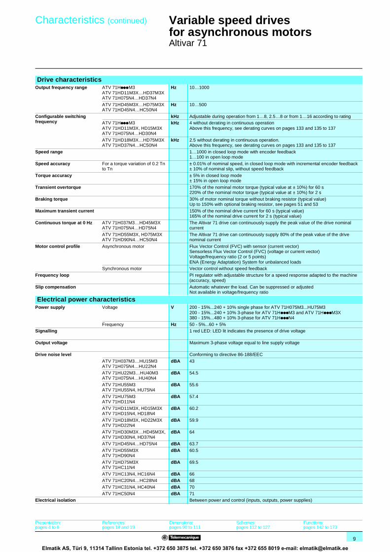
Using a motor at overspeedThe maximum output frequency can be adjusted from 10 to 1000 Hz for drives rated less than or equal to 37 kW and from 10 to 500 Hz for higher ratings.When using a standardized asynchronous motor at overspeed, check the mechanical overspeed characteristics of the selected motor with the manufacturer.Above its nominal speed corresponding to a frequency of 50/60 Hz, the motor operates with a decreasing flux and its torque decreases significantly (see the curve opposite).The application must be able to permit this type of low-torque, high-speed operation.
1 Machine torque (degressive torque)2 Machine torque (low motor torque)3 Continuous motor torqueTypical applications: wood-working machinery, broaching machines, high-speed hoisting, etc
Motor power less than drive powerAn Altivar 71 drive can power any motor with a rating lower than that for which the drive was designed. This motor/drive combination makes it suitable for applications requiring high, intermittent overtorque.Typical applications: machines with very high starting torque, grinders, kneaders, etc
Note: in this case, it is advisable to over-rate the drive to the next standard power rating immediately above that of the motor.
Example: Use an 11 kW motor with a 15 kW drive.
Power of a self-cooled motor greater than the drive powerThis motor/drive combination makes it possible to use a self-cooled motor for a greater speed range in continuous operation. The use of a motor with a higher power rating than that of the drive is only possible if the current drawn by this motor is less than or equal to the nominal drive current.
Note: Limit the motor power to the standard rating immediately above that of the drive.
Example: On a single machine, the use of a 2.2 kW drive combined with a 3 kW motor means that the machine can operate at its nominal power (2.2 kW) at low speed.1 Motor power = drive power = 2.2 kW2 2.2 kW drive combined with a 3 kW motor: greater speed range at 2.2 kW.
1
3
75/9025/3000
0,25
0,50
0,75
0,951
Hz100/12050/60
2
Using a motor at overspeed
T/Tn
1
2
50/60 Hz25/3010/1200
0,25
0,50
0,75
0,951
1,25
1
2
Power of a self-cooled motor greater than the drive power
I/In motor
Presentation:pages 4 to 7
References:pages 18 and 19
Dimensions:pages 90 to 111
Schemes:pages 112 to 127
Functions:pages 142 to 173
Elmatik AS, Türi 9, 11314 Tallinn Estonia tel. +372 650 3875 tel. +372 650 3876 fax +372 655 8019 e-mail: [email protected]

16
Operation (continued) 1 Variable speed drivesfor asynchronous motors 1
Altivar 71
Special uses (continued) Connecting motors in parallel
The nominal current of the drive must be greater than or equal to the sum of the currents of the motors to be controlled.In this case, provide external thermal protection for each motor using probes or thermal overload relays. For cable runs over a certain length, taking account of all tap links, it is advisable either to install an output filter between the drive and the motors or to use the overvoltage limitation function.
If several motors are used in parallel, there are 2 possible scenarios:b The motors have equal power ratings, in which case the torque characteristics will remain optimized after the drive has been configuredb The motors have different power ratings, in which case the torque characteristics will not be optimized for all the motors
Using a motor at constant torque up to 87/104 HzA 400 V, 50 Hz motor in connection can be used at constant torque up to 87 Hz if it is in ∆ connection.In this particular case, the initial motor power, as well as the power of the first associated drive are multiplied by √3 (it is therefore important to select a drive with a suitable rating).Example: A 2.2 kW, 50 Hz motor in connection supplies 3.8 kW at 87 Hz with a ∆ connection.
Note: Check the motor’s overspeed operating characteristics.
Using special motorsSpecial brake motors: tapered rotor or flux bypass
The magnetic field releases the brake. This type of operation with the Altivar 71 drive requires application of the voltage/frequency ratio.
Note: The no-load current may be high, operation at low speed can only be intermittent.
Resistive rotor asynchronous motorsDifferent motor control ratios available on the Altivar 71 make it possible to apply specific settings when using high-slip motors.
Altivar 71 M1In1
M2
Mx
In2
Inx
Outputfilter
In drive > In1 + In2 +…Inx
Connecting motors in parallel
Altivar 712,2 kW
Altivar 714 kW
50 Hz
∆ 87 Hz
2,2 kW1500 tr/min
3,8 kW2600 tr/min
Identical motor
87/104
230
400U (V)
50/60 Hz
Using a motor at constant torque up to 87/104 Hz
Presentation:pages 4 to 7
References:pages 18 and 19
Dimensions:pages 90 to 111
Schemes:pages 112 to 127
Functions:pages 142 to 173
Elmatik AS, Türi 9, 11314 Tallinn Estonia tel. +372 650 3875 tel. +372 650 3876 fax +372 655 8019 e-mail: [email protected]

17
Operation (continued) 1 Variable speed drivesfor asynchronous motors 1
Altivar 71
Special uses (continued)
Example of loss of output contactor
Switching the motor at the drive outputThe drive can be switched when locked or unlocked. If the drive is switched on-the-fly (drive unlocked), the motor is controlled and accelerates until it reaches the reference speed smoothly following the acceleration ramp. This use requires configuration of the automatic catching a spinning load ("catch on the fly") and the motor phase loss on output cut functions.
Typical applications: loss of safety circuit at drive output, bypass function, switching of motors connected in parallelOn new installations, it is recommended that the Power Removal safety function is used.
Test on a low power motor or without a motorIn a testing or maintenance environment the drive can be checked without having to switch to a motor with the same rating as the drive (particularly useful in the case of high power drives). This use requires deactivation of motor phase loss function.
N
t1
KM1 0
1
t2
t
t
Altivar 71 M
KM1
t1: deceleration without ramp (freewheel)t2: acceleration with ramp
Presentation:pages 4 to 7
References:pages 18 and 19
Dimensions:pages 90 to 105
Schemes:pages 112 to 127
Functions:pages 142 to 173
Elmatik AS, Türi 9, 11314 Tallinn Estonia tel. +372 650 3875 tel. +372 650 3876 fax +372 655 8019 e-mail: [email protected]

18
References 1 Variable speed drivesfor asynchronous motors 1
Altivar 71Supply voltage 200...240 V 50/60 Hz
Motor Line supply Altivar 71Powerindicated on plate (1)
Line current (2)
Apparentpower
Max. prospective line Isc
Maximum continuous current (1)
Max. transient current for
Reference (3) Weight
200 V 240 V 240 V 60 s 2 skW HP A A kVA kA A A A kg
Single phase supply voltage: 200…240 V 50/60 Hz 0.37 0.5 6.9 5.8 2.4 5 3 4.5 4.9 ATV 71H075M3 (4) 3.000
0.75 1 12 9.9 4.1 5 4.8 7.2 7.9 ATV 71HU15M3 (4) 3.0001.5 2 18.2 15.7 6.5 5 8 12 13.2 ATV 71HU22M3 (4) 3.000
2.2 3 25.9 22.1 9.2 5 11 16.5 18.1 ATV 71HU30M3 (4) 4.000
3 – 25.9 22 9.1 5 13.7 20.6 22.6 ATV 71HU40M3 (4) (5) 4.0004 5 34.9 29.9 12.4 5 17.5 26.3 28.8 ATV 71HU55M3 (4) (5) 5.500
5.5 7.5 47.3 40.1 16.7 22 27.5 41.3 45.3 ATV 71HU75M3 (4) (5) 5.500
3-phase supply voltage: 200…240 V 50/60 Hz 0.37 0.5 3.5 3.1 1.3 5 3 4.5 4.9 ATV 71H037M3 (4) 3.0000.75 1 6.1 5.3 2.2 5 4.8 7.2 7.9 ATV 71H075M3 (4) 3.000
1.5 2 11.3 9.6 4 5 8 12 13.2 ATV 71HU15M3 (4) 3.000
2.2 3 15 12.8 5.3 5 11 16.5 18.1 ATV 71HU22M3 (4) 4.0003 – 19.3 16.4 6.8 5 13.7 20.6 22.6 ATV 71HU30M3 (4) 4.000
4 5 25.8 22.9 9.5 5 17.5 26.3 28.8 ATV 71HU40M3 (4) 4.000
5.5 7.5 35 30.8 12.8 22 27.5 41.3 45.3 ATV 71HU55M3 (4) 5.5007.5 10 45 39.4 16.4 22 33 49.5 54.5 ATV 71HU75M3 (4) 7.000
11 15 53.3 45.8 19 22 54 81 89.1 ATV 71HD11M3X (4) (6) 9.000
15 20 71.7 61.6 25.6 22 66 99 109 ATV 71HD15M3X (4) (6) 9.00018.5 25 77 69 28.7 22 75 112 124 ATV 71HD18M3X (6) 19.000
22 30 88 80 33.3 22 88 132 145 ATV 71HD22M3X (6) 19.000
30 40 124 110 45.7 22 120 180 198 ATV 71HD30M3X (6) 39.00037 50 141 127 52.8 22 144 216 238 ATV 71HD37M3X (6) 39.000
45 60 167 147 61.1 22 176 264 290 ATV 71HD45M3X (6) 39.000
55 75 200 173 71.9 35 221 332 365 ATV 71HD55M3X (6) (7) (8) 59.000
75 100 271 232 96.4 35 285 428 470 ATV 71HD75M3X (6) (7) (8) 72.000
(1) These values are for a nominal switching frequency of 2.5 or 4 kHz, depending on the rating, for continuous operation.The switching frequency is adjustable from 1…16 kHz up to ATV 71HD45M3X and from 1…8 kHz for ATV 71HD55M3X and ATV 71HD75M3X drives.Above 2.5 or 4 kHz, depending on the rating, the drive decreases the switching frequency itself in the event of excessive temperature rise. For continuous operation above the nominal switching frequency, derate the nominal drive current (see derating curves on pages 133 and 135 to 137).
(2) Typical value for the indicated motor power and for the maximum prospective line Isc. (3) To order a special reinforced version for difficult environmental conditions, add S337 at the end of the reference
(except for ATV 71HpppM3X). (See the characteristics on page 8).Example: ATV 71H037M3 becomes ATV 71H037M3S337.For ATV 71HpppM3X, add 337 at the end of the reference. Example: ATV 71HD11M3X becomes ATV 71HD11M3X337.In this case, the drive is supplied with a remote graphic display terminal.
(4) Drive supplied with a remote graphic display terminal. To receive a drive without a graphic display terminal, add a Z at the end of the reference. It will then be equipped with an integrated 7-segment display terminal. This option is not available for drives operating in difficult environmental conditions (3).Example: ATV 71H037M3 without graphic terminal becomes ATV 71H037M3Z.
(5) A line choke must be used (see page 72).(6) Drive supplied without EMC filters. EMC filters are available as an option (see page 78).(7) Drive supplied as standard with a DC choke, which must be used when connecting the drive to the 3-phase supply.
For connections to the DC bus, the drive can be ordered without a DC choke by adding D at the end of the reference.Example: ATV 71HD55M3X becomes ATV 71HD55M3XD.
(8) Drive supplied without plate for EMC mounting. It is included in the kits for NEMA type 1, IP 21 or IP 31 conformity, to be ordered separately (see pages 22 and 23).
Note: please refer to the compatibility tables summarizing the possible combinations for drives, options and accessories on pages 86 to 89.
5331
58
ATV 71HU22M3Z
5327
25
ATV 71H037M3
532
724
ATV 71HD37M3X
Presentation:pages 4 to 7
Characteristics:pages 8 to 13
Dimensions:pages 90 to 103
Schemes:pages 112 to 127
Functions:pages 142 to 173
Elmatik AS, Türi 9, 11314 Tallinn Estonia tel. +372 650 3875 tel. +372 650 3876 fax +372 655 8019 e-mail: [email protected]

19
References (continued) 1 Variable speed drivesfor asynchronous motors 1
Altivar 71Supply voltage 380..0.480 V 50/60 Hz
Motor Line supply Altivar 71Powerindicated on plate (1)
Line current (2)
Apparentpower
Max. prospective line Isc
Maximum continuous current (1)
Max. transient current for
Reference Weight
380 V 480 V 380 V 60 s 2 skW HP A A kVA kA A A A kg
3-phase supply voltage: 380…480 V 50/60 Hz 0.75 1 3.7 3 2.4 5 2.3 3.5 3.8 ATV 71H075N4 (3) (4) 3.000
1.5 2 5.8 5.3 3.8 5 4.1 6.2 6.8 ATV 71HU15N4 (3) (4) 3.000
2.2 3 8.2 7.1 5.4 5 5.8 8.7 9.6 ATV 71HU22N4 (3) (4) 3.0003 – 10.7 9 7 5 7.8 11.7 12.9 ATV 71HU30N4 (3) (4) 4.000
4 5 14.1 11.5 9.3 5 10.5 15.8 17.3 ATV 71HU40N4 (3) (4) 4.000
5.5 7.5 20.3 17 13.4 22 14.3 21.5 23.6 ATV 71HU55N4 (3) (4) 5.5007.5 10 27 22.2 17.8 22 17.6 26.4 29 ATV 71HU75N4 (3) (4) 5.500
11 15 36.6 30 24.1 22 27.7 41.6 45.7 ATV 71HD11N4 (3) (4) 7.000
15 20 48 39 31.6 22 33 49.5 54.5 ATV 71HD15N4 (3) (4) 9.00018.5 25 45.5 37.5 29.9 22 41 61.5 67.7 ATV 71HD18N4 (3) 9.000
22 30 50 42 32.9 22 48 72 79.2 ATV 71HD22N4 (3) 19.000
30 40 66 56 43.4 22 66 99 109 ATV 71HD30N4 (3) 26.00037 50 84 69 55.3 22 79 118.5 130 ATV 71HD37N4 (3) 26.000
45 60 104 85 68.5 22 94 141 155 ATV 71HD45N4 (3) 44.000
55 75 120 101 79 22 116 174 191 ATV 71HD55N4 (3) 44.00075 100 167 137 109.9 22 160 240 264 ATV 71HD75N4 (3) 44.000
90 125 166 134 109.3 35 179 269 295 ATV 71HD90N4 (5) (6) 60.000
110 150 202 163 133 35 215 323 355 ATV 71HC11N4 (5) (6) 74.000132 200 239 192 157.3 35 259 388 427 ATV 71HC13N4 (5) (6) 80.000
160 250 289 233 190.2 50 314 471 518 ATV 71HC16N4 (5) (6) 110.000
200 300 357 286 235 50 387 580 638 ATV 71HC20N4 (5) (6) 140.000220 350 396 320 260.6 50 427 640 704 ATV 71HC25N4 (5) (6) 140.000
250 400 444 357 292.2 50 481 721 793
280 450 494 396 325.1 50 550 825 907 ATV 71HC28N4 (5) (6) 140.000315 500 555 444 365.3 50 616 924 1016 ATV 71HC31N4 (5) (6) 215.000
355 – 637 512 419.3 50 671 1006 1107 ATV 71HC40N4 (5) (6) 225.000
400 600 709 568 466.6 50 759 1138 1252500 700 876 699 576.6 50 941 1411 1552 ATV 71HC50N4 (5) (6) 300.000
(1) These values are for a nominal switching frequency of 2.5 or 4 kHz, depending on the rating, for continuous operation.The switching frequency is adjustable from 1…16 kHz up to ATV 71HD75N4 and from 2.5…8 kHz for ATV 71HD90N4…ATV 71HC50N4 drives.Above 2.5 or 4 kHz, depending on the rating, the drive decreases the switching frequency itself in the event of excessive temperature rise. For continuous operation above the nominal switching frequency, derate the nominal drive current (see derating curves on pages 133 and 135 to 137).
(2) Typical value for the indicated motor power and for the maximum prospective line Isc. (3) To order a special reinforced version for difficult environmental conditions, add S337 at the end of the reference
(see the characteristics on page 8).Example: ATV 71H075N4 becomes ATV 71H075N4S337.In this case, the drive is supplied with a remote graphic display terminal.ATV 71HD90N4…HC50N4 drives have been specially designed to operate in difficult environmental conditions.
(4) Drive supplied with a remote graphic display terminal. To receive a drive without a graphic display terminal, add a Z at the end of the reference. It will then be equipped with an integrated 7-segment display terminal. This option is not available for drives operating in difficult environmental conditions (3).Example: ATV 71H075N4 without graphic terminal becomes ATV 71H075N4Z.
(5) Drive supplied as standard with a DC choke, which must be used when connecting the drive to the 3-phase supply.For connections to the DC bus, the drive can be ordered without a DC choke by adding D at the end of the reference.Example: ATV 71HD90N4 becomes ATV 71HD90N4D.
(6) Drive supplied without plate for EMC mounting. It is included in the kits for NEMA type 1, IP 21 or IP 31 conformity, to be ordered separately (see pages 22 and 23).
Note: please refer to the compatibility tables summarizing the possible combinations for drives, options and accessories on pages 86 to 89.
532
723
ATV 71HU22N4
5331
58
ATV 71HU40N4Z
533
249
ATV 71HC28N4
Presentation:pages 4 to 7
Characteristics:pages 8 to 13
Dimensions:pages 90 to 103
Schemes:pages 112 to 127
Functions:pages 142 to 173
Elmatik AS, Türi 9, 11314 Tallinn Estonia tel. +372 650 3875 tel. +372 650 3876 fax +372 655 8019 e-mail: [email protected]

20
Presentation,references 1
Variable speed drivesfor asynchronous motors 1
Altivar 71Options: accessories
This adaptor is used to connect 115 V a logic signals to the logic inputs on the drive or an I/O extension card.
7 logic inputs with capacitive impedance at 60 Hz of 0.22 µF are available for connecting the logic signals:b Max. current: 200 mAb Response time: 5 ms to change from state 0 to state 1, 20 ms to change from state 1 to state 0b Logic state 0 for a voltage below 20 V, logic state 1 for a voltage between 70 V and 132 VThe power supply must be provided by a 115 V a external power supply (min. 70 V, max. 132 V).
This kit is required for ATV 71HD18M3X, HD22M3X and ATV 71HD22N4…HD75N4 drives.It enables the drive to operate at an ambient temperature of 50°C to 60°C, for example if it is mounted in an IP 54 enclosure. The circulation of air around the electronic cards prevents the formation of hot spots.Check the derating to be applied to the drive nominal current (see the derating curves on pages 133 and 135 to 137).
The kit 1 is mounted on the upper part of the drive. It is powered by the drive.It consists of:b A fan subassemblyb Fixing accessoriesb A manual
Adaptor for 115 V a logic inputs
ReferencesDescription Reference Weight
kgAdaptor for 115 V a logic inputs VW3 A3 101 –
Control card fan kit
1
5332
36
ReferencesFor drives Reference Weight
kgATV 71HD18M3X, HD22M3XATV 71HD22N4…HD37N4
VW3 A9 406 –
ATV 71HD45N4…HD75N4 VW3 A9 407 –
Dimensions:page 93
Elmatik AS, Türi 9, 11314 Tallinn Estonia tel. +372 650 3875 tel. +372 650 3876 fax +372 655 8019 e-mail: [email protected]

21
Presentation,references (continued) 1
Variable speed drivesfor asynchronous motors 1
Altivar 71Options: accessories
This kit can be used to mount the power part of the drive outside the enclosure (IP 54 degree of protection), which reduces the power dissipated into the enclosure (see page 138).With this type of mounting, the maximum internal temperature in the enclosure can then reach 60°C without it being necessary to derate the drive current.Between 50°C and 60°C, for ATV 71HD18M3X, HD22M3X and ATV 71HD22N4…HD75N4 drives, a control card fan kit must be used to prevent hot spots (see page 20). The back of the enclosure must be drilled and cut out for this type of mounting.
The kit consists of:b A metal frame of the right size for the drive ratingb Corner piecesb Sealsb A fan support (This can be used to move the fans so that they can be accessed from the front of the enclosure.)b Fixing accessoriesb A cutting and drilling templateb A manual
Kit for flush-mounting in a dust and damp proof enclosure
ReferencesFor drives Reference Weight
kgATV 71H037M3…HU15M3ATV 71H075N4…HU22N4
VW3 A9 501 2.700
ATV 71HU22M3…HU40M3ATV 71HU30N4, HU40N4
VW3 A9 502 3.100
ATV 71HU55M3ATV 71HU55N4, HU75N4
VW3 A9 503 3.700
ATV 71HU75M3ATV 71HD11N4
VW3 A9 504 4.600
ATV 71HD11M3X, HD15M3XATV 71HD15N4, HD18N4
VW3 A9 505 4.900
ATV 71HD18M3X, HD22M3XATV 71HD22N4
VW3 A9 506 3.900
ATV 71HD30N4, HD37N4 VW3 A9 507 4.200
ATV 71HD30M3X…HD45M3X VW3 A9 508 4.900
ATV 71HD45N4…HD75N4 VW3 A9 509 5.200ATV 71HD55M3X ATV 71HD90N4
VW3 A9 510 5.100
ATV 71HD75M3XATV 71HC11N4
VW3 A9 511 3.600
ATV 71HC13N4 VW3 A9 512 4.300
ATV 71HC16N4 VW3 A9 513 4.400
ATV 71HC20N4…HC28N4 Without braking unit VW3 A9 514 4.700With braking unit VW3 A9 515 4.700
ATV 71HC31N4, HC40N4 VW3 A9 516 5.900
ATV 71HC50N4 VW3 A9 517 6.200
ATV 71HU75N4 flush-mounted
533
254
ATV 71HC28N4D flush-mounted
533
255
Dimensions:pages 94 to 96
Elmatik AS, Türi 9, 11314 Tallinn Estonia tel. +372 650 3875 tel. +372 650 3876 fax +372 655 8019 e-mail: [email protected]
22
Presentation,references (continued) 1
Variable speed drivesfor asynchronous motors 1
Altivar 71Options: accessories
When the drive is mounted directly on a wall outside the enclosure, this kit can be used to ensure NEMA type 1 conformity when connecting the cables with a tube.The shielding is connected inside the kit.
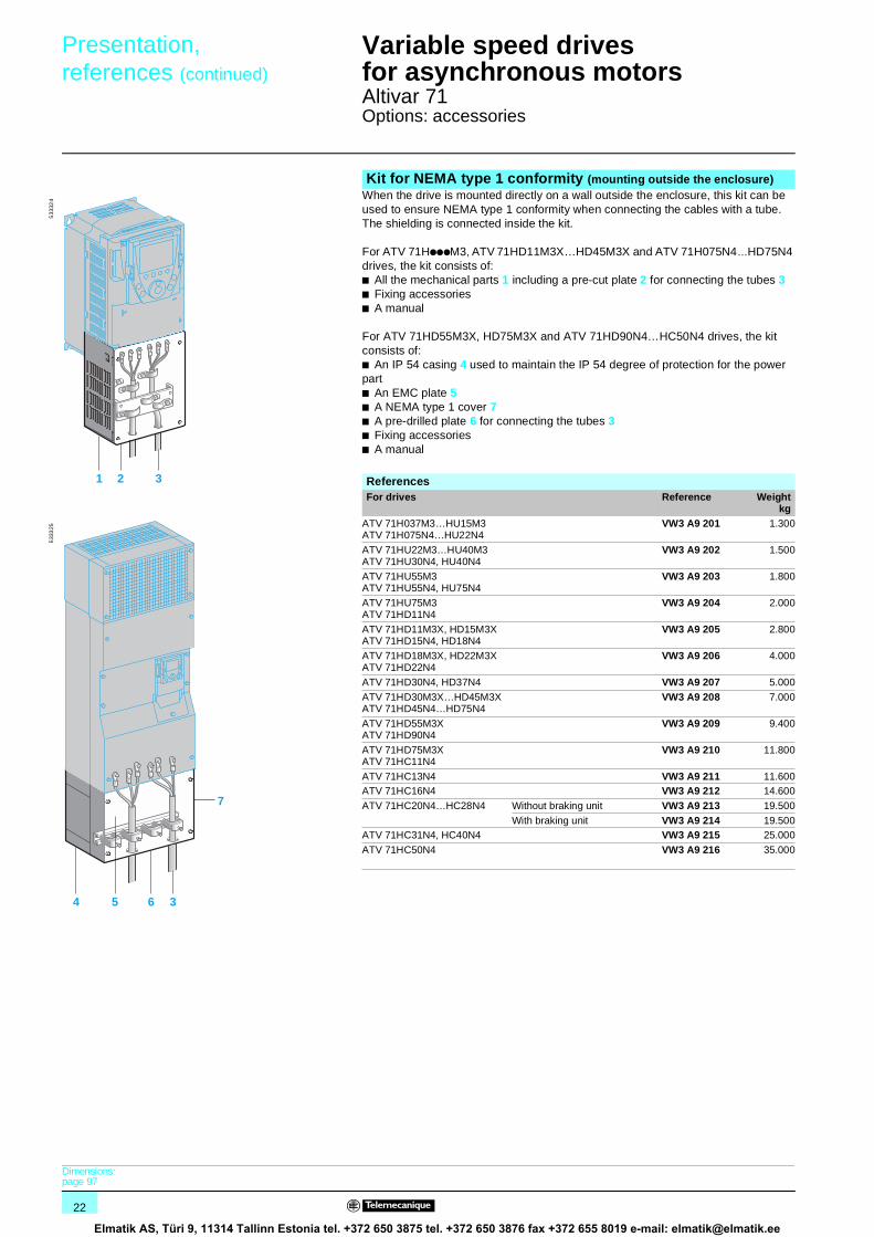
For ATV 71HpppM3, ATV 71HD11M3X…HD45M3X and ATV 71H075N4…HD75N4 drives, the kit consists of: b All the mechanical parts 1 including a pre-cut plate 2 for connecting the tubes 3b Fixing accessoriesb A manual
For ATV 71HD55M3X, HD75M3X and ATV 71HD90N4…HC50N4 drives, the kit consists of: b An IP 54 casing 4 used to maintain the IP 54 degree of protection for the power partb An EMC plate 5b A NEMA type 1 cover 7b A pre-drilled plate 6 for connecting the tubes 3b Fixing accessoriesb A manual
Kit for NEMA type 1 conformity (mounting outside the enclosure)
1 2 3
533
324
4 5 36
7
533
325
ReferencesFor drives Reference Weight
kgATV 71H037M3…HU15M3ATV 71H075N4…HU22N4
VW3 A9 201 1.300
ATV 71HU22M3…HU40M3ATV 71HU30N4, HU40N4
VW3 A9 202 1.500
ATV 71HU55M3ATV 71HU55N4, HU75N4
VW3 A9 203 1.800
ATV 71HU75M3ATV 71HD11N4
VW3 A9 204 2.000
ATV 71HD11M3X, HD15M3XATV 71HD15N4, HD18N4
VW3 A9 205 2.800
ATV 71HD18M3X, HD22M3XATV 71HD22N4
VW3 A9 206 4.000
ATV 71HD30N4, HD37N4 VW3 A9 207 5.000
ATV 71HD30M3X…HD45M3XATV 71HD45N4…HD75N4
VW3 A9 208 7.000
ATV 71HD55M3X ATV 71HD90N4
VW3 A9 209 9.400
ATV 71HD75M3XATV 71HC11N4
VW3 A9 210 11.800
ATV 71HC13N4 VW3 A9 211 11.600ATV 71HC16N4 VW3 A9 212 14.600
ATV 71HC20N4…HC28N4 Without braking unit VW3 A9 213 19.500
With braking unit VW3 A9 214 19.500ATV 71HC31N4, HC40N4 VW3 A9 215 25.000
ATV 71HC50N4 VW3 A9 216 35.000
Dimensions:page 97
Elmatik AS, Türi 9, 11314 Tallinn Estonia tel. +372 650 3875 tel. +372 650 3876 fax +372 655 8019 e-mail: [email protected]

23
Presentation,references (continued) 1
Variable speed drivesfor asynchronous motors 1
Altivar 71Options: accessories
When the drive is mounted directly on a wall outside the enclosure, this kit can be used to ensure conformity with IP 21 or IP 31 degree of protection when connecting the cables with a cable gland.The shielding is connected inside the kit.
For ATV 71HpppM3, ATV 71HD11M3X…HD45M3X and ATV 71H075N4…HD75N4 drives, the kit conforms to IP 21 degree of protection.It consists of: b All the mechanical parts 1 including a drilled plate 2 for fixing the cable glands 3b Fixing accessoriesb A manual
For ATV 71HD55M3X, HD75M3X and ATV 71HD90N4…HC50N4 drives, the kit conforms to IP 31 degree of protection.It consists of: b An IP 54 casing 4 used to maintain the IP 54 degree of protection for the power partb An EMC plate with cable clamps 5b An IP 31 cover 6b Fixing accessoriesb A manual
Kits for IP 21 or IP 31 conformity (mounting outside the enclosure)
1 2 3
5333
26
4 5
6
533
327
ReferencesFor drives Degree of
protectionReference Weight
kgATV 71H037M3…HU15M3ATV 71H075N4…HU22N4
IP 21 VW3 A9 101 1.300
ATV 71HU22M3…HU40M3ATV 71HU30N4, HU40N4
IP 21 VW3 A9 102 1.500
ATV 71HU55M3ATV 71HU55N4, HU75N4
IP 21 VW3 A9 103 1.800
ATV 71HU75M3ATV 71HD11N4
IP 21 VW3 A9 104 2.000
ATV 71HD11M3X, HD15M3XATV 71HD15N4, HD18N4
IP 21 VW3 A9 105 2.800
ATV 71HD18M3X, HD22M3XATV 71HD22N4
IP 21 VW3 A9 106 4.000
ATV 71HD30N4, HD37N4 IP 21 VW3 A9 107 5.000
ATV 71HD30M3X…HD45M3XATV 71HD45N4…HD75N4
IP 21 VW3 A9 108 7.000
ATV 71HD55M3X ATV 71HD90N4
IP 31 VW3 A9 109 9.400
ATV 71HD75M3XATV 71HC11N4
IP 31 VW3 A9 110 11.800
ATV 71HC13N4 IP 31 VW3 A9 111 11.600ATV 71HC16N4 IP 31 VW3 A9 112 14.600
ATV 71HC20N4…HC28N4 Without braking unit IP 31 VW3 A9 113 19.500
With braking unit IP 31 VW3 A9 114 19.500ATV 71HC31N4, HC40N4 IP 31 VW3 A9 115 25.000
ATV 71HC50N4 IP 31 VW3 A9 116 35.000
Dimensions:page 97
Elmatik AS, Türi 9, 11314 Tallinn Estonia tel. +372 650 3875 tel. +372 650 3876 fax +372 655 8019 e-mail: [email protected]

24
Presentation,references (continued) 1
Variable speed drivesfor asynchronous motors 1
Altivar 71Options: accessories
Substitution kit for Altivar 58 or Altivar 58F drivesThis kit 1 is used to fit an Altivar 71 drive in the place of an Altivar 58 or Altivar 58F drive using the same fixing holes. It includes the mechanical adaptors required for mounting.
KitsOld drive Motor Replaced by Reference Weight
PowerkW HP kg
Supply voltage 200…240 V single phase High torque application (170% Tn)
ATV 58HU09M2 0.37 0.5 ATV 71H075M3 VW3 A9 301 –
ATV 58HU18M2 0.75 1 ATV 71HU15M3 VW3 A9 301 –ATV 58HU29M2 1.5 2 ATV 71HU22M3 VW3 A9 303 –
ATV 58HU41M2 2.2 3 ATV 71HU30M3 VW3 A9 303 –
ATV 58HU72M2 3 – ATV 71HU40M3 VW3 A9 304 –ATV 58HU90M2 4 5 ATV 71HU55M3 VW3 A9 306 –
ATV 58HD12M2 5.5 7.5 ATV 71HU75M3 VW3 A9 306 –
Supply voltage 200…240 V three-phase High torque application (170% Tn)
ATV 58HU29M2 1.5 2 ATV 71HU15M3 VW3 A9 302 –
ATV 58HU41M2 2.2 3 ATV 71HU22M3 VW3 A9 303 –ATV 58HU54M2 3 – ATV 71HU30M3 VW3 A9 304 –
ATV 58HU72M2 4 5 ATV 71HU40M3 VW3 A9 304 –
ATV 58HU90M2 5.5 7.5 ATV 71HU55M3 VW3 A9 306 –ATV 58HD12M2 7.5 10 ATV 71HU75M3 VW3 A9 307 –
ATV 58HD16M2X 11 15 ATV 71HD11M3X VW3 A9 309 –
ATV 58HD23M2X 15 20 ATV 71HD15M3X VW3 A9 309 –ATV 58HD28M2X 18.5 25 ATV 71HD18M3X VW3 A9 312 –
ATV 58HD33M2X 22 30 ATV 71HD22M3X VW3 A9 312 –
ATV 58HD46M2X 30 40 ATV 71HD30M3X VW3 A9 314 –
Supply voltage 380…480 V three-phase High torque application (170% Tn)
ATV 58HU18N4 0.75 1 ATV 71H075N4 VW3 A9 302 –ATV 58HU29N4 1.5 2 ATV 71HU15N4 VW3 A9 302 –
ATV 58HU41N4 2.2 3 ATV 71HU22N4 VW3 A9 303 –
ATV 58HU54N4 3 – ATV 71HU30N4 VW3 A9 304 –ATV 58HU72N4 4 5 ATV 71HU40N4 VW3 A9 304 –
ATV 58HU90N4 5.5 7.5 ATV 71HU55N4 VW3 A9 305 –
ATV 58HD12N4 7.5 10 ATV 71HU75N4 VW3 A9 306 –ATV 58HD16N4 11 15 ATV 71HD11N4 VW3 A9 307 –
ATV 58HD23N4 15 20 ATV 71HD15N4 VW3 A9 308 –
ATV 58HD28N4 18.5 25 ATV 71HD18N4 VW3 A9 309 –ATV 58HD33N4 22 30 ATV 71HD22N4 VW3 A9 310 –
ATV 58HD46N4 30 40 ATV 71HD30N4 VW3 A9 311 –
ATV 58HD54N4 37 50 ATV 71HD37N4 VW3 A9 313 –ATV 58HD64N4 45 60 ATV 71HD45N4 VW3 A9 315 –
ATV 58HD79N4 55 75 ATV 71HD55N4 VW3 A9 315 –
1
VW3 A9 304
5332
38
Elmatik AS, Türi 9, 11314 Tallinn Estonia tel. +372 650 3875 tel. +372 650 3876 fax +372 655 8019 e-mail: [email protected]

25
References (continued) 1 Variable speed drivesfor asynchronous motors 1
Altivar 71Options: accessories
Kits (continued)Old drive Motor Replaced by Reference Weight
PowerkW HP kg
Supply voltage 200…240 V three-phase Standard torque applications (120% Tn)
ATV 58HD16M2X 15 20 ATV 71HD15M3X VW3 A9 309 –
ATV 58HD23M2X 18.5 25 ATV 71HD18M3X VW3 A9 310 –ATV 58HD28M2X 22 30 ATV 71HD22M3X VW3 A9 312 –
ATV 58HD33M2X 30 40 ATV 71HD30M3X VW3 A9 314 –
ATV 58HD46M2X 37 50 ATV 71HD37M3X VW3 A9 314 –
Supply voltage 380…480 V three-phase Standard torque applications (120% Tn)
ATV 58HD28N4 22 30 ATV 71HD22N4 VW3 A9 310 –ATV 58HD33N4 30 40 ATV 71HD30N4 VW3 A9 311 –
ATV 58HD46N4 37 50 ATV 71HD37N4 VW3 A9 311 –
ATV 58HD54N4 45 60 ATV 71HD45N4 VW3 A9 315 –ATV 58HD64N4 55 75 ATV 71HD55N4 VW3 A9 315 –
ATV 58HD79N4 75 100 ATV 71HD75N4 VW3 A9 315 –
1
VW3 A9 315
5332
37
Elmatik AS, Türi 9, 11314 Tallinn Estonia tel. +372 650 3875 tel. +372 650 3876 fax +372 655 8019 e-mail: [email protected]

26
Presentation,references 1
Variable speed drivesfor asynchronous motors 1
Altivar 71Options: dialogue
(1) In this case, use a VW3 A1 104 Rpp remote connecting cable, which must be ordered separately (see above).
(2) To be mounted on remote mounting kit VW3 A1 102 (for mounting on an enclosure door), which must be ordered separately (see above).
Remote graphic display terminal(this display terminal can be supplied with the drive or ordered separately)
This display terminal is attached to the front of the drive. In the case of drives supplied without a graphic display terminal, it covers the integrated 7-segment display terminal.It can be:b Used remotely in conjunction with the appropriate accessories (see below)b Connected to several drives using multidrop link components (see page 27)It is used:b To control, adjust and configure the driveb To display the current values (motor, input/output values, etc.)b To save and download configurations; 4 configuration files can be saved.The terminal’s maximum operating temperature is 60°C and it features IP 54 protection. Description
1 Graphic display:- 8 lines, 240 x 160 pixels- Large digits that can be read from 5 m away- Supports display of bar charts
2 Assignable function keys F1, F2, F3, F4:- Dialogue functions: direct access, help screens, navigation- Application functions: “Local Remote”, preset speed
3 “STOP/RESET”: local control of motor stop/fault reset4 “RUN”: local control of motor operation5 Navigation button:
- Press: saves the current value (ENT)- Turn ±: increases or decreases the value, takes you to the next or previous line.
6 “FWD/REV”: reverses the direction of rotation of the motor7 “ESC”: aborts a value, a parameter or a menu to return to the previous selection
Note: Keys 3, 4 and 6 can be used to control the drive directly.
References
5221
48
1
2
3
4
7
6
5
Description N° Reference Weightkg
Remote graphic display terminal 1 VW3 A1 101 0.145
32
1
4
5
1
4
Graphic display terminal accessoriesThe available accessories are:b A remote mounting kit for mounting on an enclosure door with IP 54 degree of protection. It includes:v All the mechanical fittingsv The screws and boltsb A transparent door which attaches to the remote mechanics to achieve IP 65 degree of protectionb A cable equipped with two RJ45 connectors so that the graphic display terminal can be connected to the Altivar 71 drive (1, 3, 5 or 10 m lengths available)b An RJ45 female/female adapter for connecting the VW3 A1 101 graphic display terminal to the VW3 A1 104 Rppp remote cable
ReferencesDescription N° Length
mDegree of protection
Reference Weightkg
Remote mounting kit (1) 2 – IP 54 VW3 A1 102 0.150
Door (2) 3 – IP 65 VW3 A1 103 0.040
Remote cablesEquipped with 2 RJ45 connectors
4 1 – VW3 A1 104 R10 0.0504 3 – VW3 A1 104 R30 0.150
4 5 – VW3 A1 104 R50 0.250
4 10 – VW3 A1 104 R100 0.500RJ45 female/femaleadaptor
5 – – VW3 A1 105 0.010
Dimensions:page 98
Elmatik AS, Türi 9, 11314 Tallinn Estonia tel. +372 650 3875 tel. +372 650 3876 fax +372 655 8019 e-mail: [email protected]

27
References (continued) 1 Variable speed drivesfor asynchronous motors 1
Altivar 71Options: dialogue
Multidrop link componentsThese components enable a graphic display terminal to be connected to several drives via a multidrop link. This multidrop link is connected to the Modbus terminal port on the front of the drive.
Connection accessories Description N° Sold in lots
ofUnit reference
Weightkg
Modbus splitter box10 RJ45 connectors and1 screw terminal
1 – LU9 GC3 0.500
Modbus T-junction boxes
With integrated 0.3 m cable
2 – VW3 A8 306 TF03 –
With integrated 1 m cable
2 – VW3 A8 306 TF10 –
Modbusline terminator
For RJ45 connector
R = 120 ΩC = 1 nF
3 2 VW3 A8 306 RC 0.010
Remote mounting kit
For the VW3 A1 101 graphic display terminal
4 – VW3 A1 102 0.150
Connecting cables(equipped with 2 RJ45 connectors)Used with N° Length
mReference Weight
kgFor remote operation of the Altivar 71 and the VW3 A1 101 graphic display terminal
5 1 VW3 A1 104 R10 0.050
3 VW3 A1 104 R30 0.150
5 VW3 A1 104 R50 0.250
10 VW3 A1 104 R100 0.500
Modbus bus 6 0.3 VW3 A8 306 R03 0.025
1 VW3 A8 306 R10 0.060
3 VW3 A8 306 R30 0.130
1
66
5 52
2 2 3
26
2
23
4
Example of connection via multidrop link
VW3 A1 102ATV 71
ATV 71
PowerSuite software workshop The PowerSuite software workshop offers the following benefits:b Messages can be displayed in plain text in several languages (English, French, German, Italian and Spanish)b Work can be prepared in the design office without having to connect the drive to the PCb Configurations and settings can be saved to floppy disk or hard disk and downloaded to the driveb Print facilityb Altivar 58 or Altivar 58F files can be converted for transfer to an Altivar 71 driveb Oscillograms can be displayed
See pages 176 to 179.
5332
19
PowerSuite software workshop
Dimensions:page 98
Elmatik AS, Türi 9, 11314 Tallinn Estonia tel. +372 650 3875 tel. +372 650 3876 fax +372 655 8019 e-mail: [email protected]

28
Presentation,characteristics 1
Variable speed drivesfor asynchronous motors 1
Altivar 71Options: encoder interface cards
(1) Minimum encoder power supply 4.5 V.(2) Minimum encoder power supply 8 V.(3) Shielded cable containing 3 twisted pairs at intervals of between 20 and 50 mm.
Connect the shielding to earth at both ends.Minimum recommended conductor cross-section for a minimum encoder voltage in order to limit line voltage drops.
Presentation Encoder interface cards are used for Flux Vector Control operation with sensor (FVC mode) which improves drive performance irrespective of the state of the motor load:b Zero speed torqueb Accurate speed regulationb Torque accuracyb Shorter response times on a torque surgeb Improved dynamic performance in transient state
In other control modes (voltage vector control, voltage/frequency ratio), the encoder interface card improves static speed accuracy.
Encoder interface cards can also be used for machine safety irrespective of the control type:b Overspeed detectionb Load veering detection
Encoder interface cards can also transmit an Altivar 71 drive reference provided by the encoder input. This use is specific to synchronizing the speed of several drives.
Three types of card are available depending on the encoder technology:b RS 422 compatible differential outputsb open collector outputs (NPN)b push-pull outputs
The card is inserted into a dedicated slot.
CharacteristicsEncoder interface card with RS 422 compatible differential outputsType of card VW3 A3 401 VW3 A3 402
Power(supplied by the card)
Voltage 5 V c (min. 5 V, max. 5.5 V) 15 V c (min. 15 V, max. 16 V)
Maximum current 200 mA 175 mAShort-circuit and overload protection
Maximum operating frequency 300 kHz
Input signals A, A, B, BImpedance 440 Ω
Number of pulses/encoder revolution 5000 maximumThe maximum high-speed frequency should not exceed 300 kHz
Maximum consumption current of encoder 100 mA (1) 200 mA (1) 100 mA (2) 200 mA (2)
Minimum recommendedcross-section ofconductors (3)
For a maximum cable length of 25 m
0.2 mm2
(AWG 24)0.5 mm2
(AWG 20)0.2 mm2
(AWG 24)
For a maximum cable length of 50 m
0.5 mm2
(AWG 20)0.75 mm2
(AWG 18)0.2 mm2
(AWG 24)
For a maximum cable length of 100 m
0.75 mm2
(AWG 18)1.5 mm2
(AWG 15)0.2 mm2
(AWG 24)
For a maximum cable length of 1,000 m
– 0.5 mm2
(AWG 20)1 mm2
(AWG 17)
VW3 A3 401
532
727
Schemes:page 121
Elmatik AS, Türi 9, 11314 Tallinn Estonia tel. +372 650 3875 tel. +372 650 3876 fax +372 655 8019 e-mail: [email protected]

29
Characteristics (continued),references 1
Variable speed drivesfor asynchronous motors 1
Altivar 71Options: encoder interface cards
(1) Minimum encoder power supply 10 V.(2) Minimum encoder power supply 14 V.(3) Shielded cable containing 3 twisted pairs at intervals of between 20 and 50 mm.
Connect the shielding to earth at both ends.Minimum recommended conductor cross-section for a minimum encoder voltage in order to limit line voltage drops.
(4) The Altivar 71 cannot support more than one encoder interface card. Please refer to the compatibility tables summarizing the possible combinations for drives, options and accessories on pages 86 to 89.
Characteristics (continued)Encoder interface card with open collector outputsType of card VW3 A3 403 VW3 A3 404
Power(supplied by the card)
Voltage 12 V c (min. 12 V, max. 13 V) 15 V c (min. 15 V, max. 16 V)Maximum current 175 mA
Short-circuit and overload protection
Maximum operating frequency 300 kHzInput signals A, A, B, B
Impedance 1 kΩNumber of pulses/encoder revolution 5000 maximum
The maximum high-speed frequency should not exceed 300 kHz
Maximum consumption current of encoder 100 mA (1) 175 mA (1) 100 mA (1) 175 mA (1)Minimum recommendedcross-section ofconductors (2)
For a maximum cable length of 100 m
0.2 mm2
(AWG 24)0.5 mm2
(AWG 20)0.2 mm2
(AWG 24)For a maximum cable length of 200 m
0.5 mm2
(AWG 20)0.75 mm2
(AWG 18)0.2 mm2
(AWG 24)For a maximum cable length of 500 m
1 mm2
(AWG 17)1.5 mm2
(AWG 15)0.5 mm2
(AWG 20)For a maximum cable length of 1,000 m
– 0.75 mm2
(AWG 18)1.5 mm2
(AWG 15)
Encoder interface card with push-pull outputsType of card VW3 A3 405 VW3 A3 406 VW3 A3 407
Power(supplied by the card)
Voltage 12 V c (min. 12 V, max. 13 V) 15 V c (min. 15 V, max. 16 V) 24 V c (min. 20 V, max. 30 V)
Maximum current 175 mA 100 mAShort-circuit and overload protection
Maximum operating frequency 300 kHz
Input signals A, A, B, BImpedance 1 kΩ 1.6 kΩState 0 If <1.5 V
State 1 If > 7.7 V and < 13 V If > 7.7 V and < 16 V If > 11.5 V and < 25 VNumber of pulses/encoder revolution 5000 maximum
The maximum high-speed frequency should not exceed 300 kHzMaximum consumption current of encoder 100 mA (1) 175 mA (1) 100 mA (1) 175 mA (1) 100 mA (2)
Minimum recommendedcross-section ofconductors (3)
For a maximum cable length of 100 m
0.2 mm2
(AWG 24)0.5 mm2
(AWG 20)0.2 mm2
(AWG 24)
For a maximum cable length of 200 m
0.5 mm2
(AWG 20)0.75 mm2
(AWG 18)0.2 mm2
(AWG 24)
For a maximum cable length of 500 m
1 mm2
(AWG 17)1.5 mm2
(AWG 15)0.5 mm2
(AWG 20)0.2 mm2
(AWG 24)
For a maximum cable length of 1,000 m
– 0.75 mm2
(AWG 18)1.5 mm2
(AWG 15)0.5 mm2
(AWG 20)
ReferencesEncoder interface cards (4)Description Voltage
VReference Weight
kgEncoder interface cards with RS 422 compatible differential outputs
5 VW3 A3 401 0.200
15 VW3 A3 402 0.200Encoder interface cards with open collector outputs
12 VW3 A3 403 0.200
15 VW3 A3 404 0,200
Encoder interface cards with push-pull outputs 12 VW3 A3 405 0.20015 VW3 A3 406 0.200
24 VW3 A3 407 0.200
Schemes:page 121
Elmatik AS, Türi 9, 11314 Tallinn Estonia tel. +372 650 3875 tel. +372 650 3876 fax +372 655 8019 e-mail: [email protected]

30
Presentation,characteristics 1
Variable speed drivesfor asynchronous motors 1
Altivar 71Options: I/O extension cards
Presentation Altivar 71 drives can be specially adapted to particular application areas by installing I/O extension cards.
Two models are available:b Card with logic I/O featuring:v 1 relay logic output (“C/O” contact)v 4 x 24 V c positive or negative logic inputsv 2 x 24 V c open collector positive or negative logic outputsv 1 input for PTC probes
b Card with extended I/O featuring:v 1 differential current analog input (0…20 mA)v 1 software-configurable voltage (0…10 V c) or current (0…20 mA) analog inputv 2 software-configurable voltage ( ± 10 V c, 0…10 V) or current (0…20 mA) analog outputsv 1 relay logic outputv 4 x 24 V c positive or negative logic inputsv 2 x 24 V c open collector positive or negative logic outputsv 1 input for PTC probesv 1 frequency control input
CharacteristicsLogic I/O card VW3 A3 201
Internal supplies available Short-circuit and overload protection:b 1 x 24 V c supply (min. 21 V, max. 27 V), maximum current 200 mA for the complete drive
and I/O extension card assemblyb 1 x - 10.5 V c supply (± 5%) for the reference potentiometer (1 to 10 kΩ), max. current 10 mA
Configurablerelay outputs
R3A, R3B, R3C 1 relay logic output, one “N/C” contact and one “N/O” contact with common point.Minimum switching capacity: 3 mA for 24 V cMaximum switching capacity:b on resistive load (cos ϕ = 1): 5 A for 250 V a or 30 V cb on inductive load (cos ϕ = 0.4 and L/R = 7 ms): 2 A for 250 V a or 30 V c
Electrical service life: 100,000 operationsMaximum response time: 7 ms ± 0.5 ms
Logic inputs LI7…LI10 4 programmable logic inputs, 24 V c, compatible with level 1 PLC, IEC 65A-68 standardImpedance 3.5 kΩMaximum voltage: 30 VMultiple assignment makes it possible to configure several functions on one inputMaximum sampling time: 2 ms ± 0.5 ms
Positive logic (Source) State 0 if y 5 V or logic input not wired, state 1 if u 11 V
Negative logic (Sink) State 0 if u 16 V or logic input not wired, state 1 if y 10 V
Logic outputs LO1, LO2 2 assignable open collector positive logic (Source) outputs, compatible with level 1 PLC, IEC 65A-68 standard24 V c internal or 24 V c external power supply (min. 12 V, max. 30 V)Maximum current: 200 mALogic output common (CLO) isolated from other signalsMaximum sampling time: 2 ms ± 0.5 ms. The active state is software-configurable as is a delay for each switching operation
Input for PTC probes TH1+/TH1- 1 input for a maximum of 6 PTC probes mounted in series:b nominal value < 1.5 kΩb trip resistance 3 kΩ, reset value 1.8 kΩb short-circuit protection < 50 Ω
Maximum I/O connection capacityand tightening torque
1.5 mm2 (AWG 16)0.25 Nm
VW3 A3 202
5327
28
Schemes:page 120
Elmatik AS, Türi 9, 11314 Tallinn Estonia tel. +372 650 3875 tel. +372 650 3876 fax +372 655 8019 e-mail: [email protected]

31
Characteristics (continued),references 1
Variable speed drivesfor asynchronous motors 1
Altivar 71Options: I/O extension cards
(1) The Altivar 71 cannot support more than one I/O card with the same reference. Please refer to the compatibility tables summarizing the possible combinations for drives, options and accessories on pages 86 to 89.
Characteristics (continued)Extended I/O card VW3 A3 202
Internal supplies available Short-circuit and overload protection:b 1 x 24 V c supply (min. 21 V, max. 27 V), max. current 200 mA for the complete drive and
I/O extension card assemblyb 1 x - 10.5 V c supply (± 5%) for the reference potentiometer (1 to 10 kΩ), max. current
10 mA
Analog inputs AI AI3+/AI3- 1 X-Y mA differential current analog input by programming X and Y from 0 to 20 mA, with impedance 250 ΩMaximum sampling time: 5 ms ± 1 msResolution: 11 bits + 1 sign bitAccuracy: ± 0.6% for a temperature variation of 60°CLinearity: ± 0.15% of the maximum value
AI4 1 software-configurable current or voltage analog input:b voltage analog input 0…10 V c, impedance 30 kΩ (maximum safe voltage 24 V)b X-Y mA current analog input by programming X and Y from 0 to 20 mA, with impedance 250 Ω
Maximum sampling time: 5 ms ± 1 msResolution: 11 bitsAccuracy: ± 0.6% for a temperature variation of 60°CLinearity: ± 0.15% of the maximum value
Analog outputs AO2, AO3 2 software-configurable current or voltage analog outputs:b voltage analog output ± 10 V c, 0…10 V, minimum load impedance 470 Ωb X-Y mA current analog output by programming X and Y from 0 to 20 mA, maximum load
impedance 500 ΩMaximum sampling time: 5 ms ± 1 msResolution: 10 bitsAccuracy: ± 1% for a temperature variation of 60°CLinearity: ± 0.2% of the maximum value
Configurable relay outputs R4A, R4B, R4C 1 relay logic output, one “N/C” contact and one “N/O” contact with common point.Minimum switching capacity: 3 mA for 24 V cMaximum switching capacity:b on resistive load (cos ϕ = 1): 5 A for 250 V a or 30 V c b on inductive load (cos ϕ = 0.4 and L/R = 7 ms): 1.5 A for 250 V a or 30 V c
Electrical service life: 100,000 operationsMaximum response time: 10 ms ± 1 ms
Logic inputs LI11…LI14 4 programmable logic inputs, 24 V c, compatible with level 1 PLC, IEC 65A-68 standardImpedance 3.5 kΩMaximum voltage: 30 VMultiple assignment makes it possible to configure several functions on one inputMaximum sampling time: 5 ms ± 1 ms
Positive logic (Source) State 0 if y 5 V or logic input not wired, state 1 if u 11 V
Negative logic (Sink) State 0 if u 16 V or logic input not wired, state 1 if y 10 VLogic outputs LO3, LO4 2 x 24 V c assignable open collector positive logic (Source) or negative logic (Sink) outputs,
compatible with level 1 PLC, IEC 65A-68 standardMaximum voltage: 30 VMaximum current: 200 mALogic output common (CLO) isolated from other signalsMaximum sampling time: 5 ms ± 1 ms. The active state is software-configurable as is a delay for each switching operation
Input for PTC probes TH2+/TH2- 1 input for a maximum of 6 PTC probes mounted in series:b nominal value < 1.5 kΩb trip resistance 3 kΩ, reset value 1.8 kΩb short-circuit protection < 50 Ω
Frequency control input RP Frequency range: 0…30 kHzCyclic ratio: 50 % ± 10 %Maximum sampling time: 5 ms ± 1 msMaximum input voltage 30 V, 15 mAAdd a resistor if the input voltage is greater than 5 V (510 Ω for 12 V, 910 Ω for 15 V, 1.3 kΩ for 24 V)State 0 if < 1.2 V, state 1 if > 3.5 V
Maximum I/O connection capacityand tightening torque
1.5 mm2 (AWG 16)0.25 Nm
ReferencesI/O extension cards (1)Description Reference Weight
kgLogic I/O card VW3 A3 201 0.300
Extended I/O card VW3 A3 202 0.300
Schemes:page 120
Elmatik AS, Türi 9, 11314 Tallinn Estonia tel. +372 650 3875 tel. +372 650 3876 fax +372 655 8019 e-mail: [email protected]

32
Presentation,description 1
Variable speed drivesfor asynchronous motors 1
Altivar 71Option: “Controller Inside” programmable card
Presentation
The “Controller Inside” programmable card is used to adapt the variable speed drive to specific applications by integrating control system functions.
Various predefined configurable applications are sold by Telemecanique and its partners. The PS 1131 software workshop for PC is used for programming and debugging new applications, quickly and in an open-ended manner (see page 35). It is not possible to transfer the program from the card to the PC, which enables us to protect our know-how.
A single “Controller Inside” programmable card can be fitted in the Altivar 71 drive. It can be combined with another option card (I/O extension or communication). Consult the summary tables of possible drive, option and accessory combinations (see pages 86 to 89).
The “Controller Inside” programmable card has:b 10 logic inputs, 2 of which can be used for 2 counters or 4 of which can be used for 2 incremental encodersb 2 analog inputsb 6 logic outputsb 2 analog outputsb A master port for the CANopen busb A PC port for programming with the PS 1131 software workshopIf the power consumption table does not exceed 200 mA, this card can be powered by the drive. Otherwise, an external 24 V c power supply must be used.
The “Controller Inside” programmable card can also use:b The drive I/Ob The I/O extension card I/Ob The encoder interface card points counterb The drive parameters (speed, current, torque, etc)
Description 1 RJ45 connector for connecting the PS 1131 software workshop via an RS 485
serial link. Connection to the PC is via a cable and an RS 232/RS 485 converter included in the PowerSuite for PC connection kit, VW3 A8 106.
2 9-way male SUB-D connector for connection to the CANopen bus.
3 Connector with removable screw terminals, 6 contacts at intervals of 3.81 for the 24 V c power supply and 4 logic inputs.
4 3 connectors with removable screw terminals, 6 contacts at intervals of 3.81 for 6 logic inputs, 6 logic outputs, 2 analog inputs, 2 analog outputs and 2 commons.
5 5 LEDs, comprising:b 1 to indicate the presence of the 24 V c power supplyb 1 to indicate a program execution faultb 2 to indicate the CANopen bus communication statusb 1 controlled by the application program
1 2 3
4
532
835
5
Characteristics:page 34
Functions:pages 35 to 38
References:page 39
Schemes:page 121
Elmatik AS, Türi 9, 11314 Tallinn Estonia tel. +372 650 3875 tel. +372 650 3876 fax +372 655 8019 e-mail: [email protected]

33
Description (continued) 1 Variable speed drivesfor asynchronous motors 1
Altivar 71Option: “Controller Inside” programmable card
Dialogue
Human-machine dialogue with the application programmed in the “Controller Inside” programmable card is possible using: b The Altivar 71 graphic display terminalb A Magelis industrial HMI terminal connected to the drive Modbus portb A Magelis industrial HMI terminal connected to the Ethernet TCP/IP network (if the drive is equipped with an Ethernet TCP/IP communication card)
A graphic terminal menu is dedicated to the “Controller Inside” programmable card. This menu can be customized by the card program according to the application.
Any industrial HMI terminal which supports the Modbus protocol can be used to display and modify the “Controller Inside” programmable card parameters. The drive Modbus server provides access to 2 Kwords (% MW, etc) in the card.
Master CANopen communication
The master CANopen port on the “Controller Inside” programmable card can be used to extend the I/O capacity and to control other CANopen slave devices.
Communication with a PLC
The Altivar 71 drive equipped with a “Controller Inside” programmable card fits easily into complex architectures.Regardless of which bus or network is being used (Ethernet TCP/IP, Modbus/Uni-Telway, Fipio, Modbus Plus, Profibus DP, INTERBUS, etc), the PLC can communicate with the “Controller Inside” programmable card and the drive. The periodic variables can still be configured as required.
Clock
A clock backed up by a lithium battery makes it possible to have a log of events that have occurred. When the “Controller Inside” programmable card is installed in the drive, the drive faults are automatically time and date-stamped without special programming.
Sensors
XBT MagelisATV 71
Modbus bus
Independent machine with multiwire system
ATV 31 ATV 31 Advantys STB distributed I/O
FTB 1CN
ATV 71
CANopen bus
Independent machine with CANopen bus
Sensors ATV 31 FTB 1CN
CANopen bus
Ethernet TCP/IP network
Premium
ATV 71ATV 71
XBT Magelis
Modular machine with Ethernet TCP/IP network
Characteristics:page 34
Functions:pages 35 to 38
References:page 39
Schemes:page 121
Elmatik AS, Türi 9, 11314 Tallinn Estonia tel. +372 650 3875 tel. +372 650 3876 fax +372 655 8019 e-mail: [email protected]
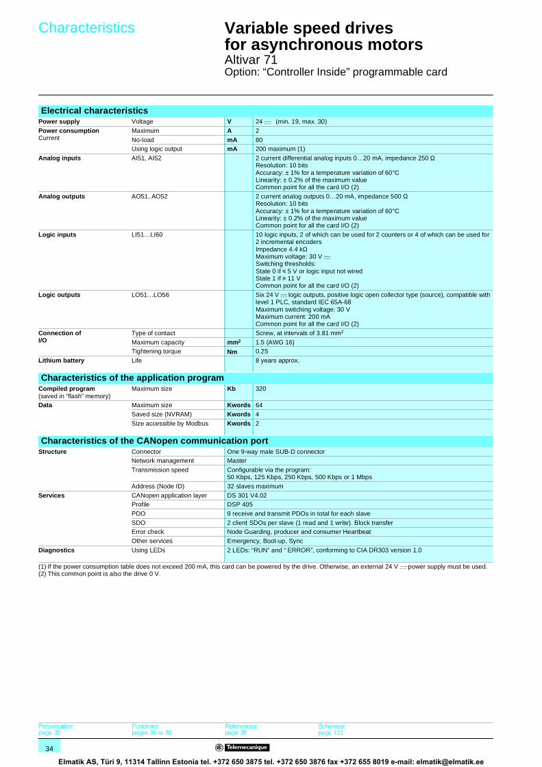
34
Characteristics 1 Variable speed drivesfor asynchronous motors 1
Altivar 71Option: “Controller Inside” programmable card
Electrical characteristicsPower supply Voltage V 24 c (min. 19, max. 30)
Power consumptionCurrent
Maximum A 2
No-load mA 80Using logic output mA 200 maximum (1)
Analog inputs AI51, AI52 2 current differential analog inputs 0…20 mA, impedance 250 ΩResolution: 10 bitsAccuracy: ± 1% for a temperature variation of 60°CLinearity: ± 0.2% of the maximum valueCommon point for all the card I/O (2)
Analog outputs AO51, AO52 2 current analog outputs 0…20 mA, impedance 500 ΩResolution: 10 bitsAccuracy: ± 1% for a temperature variation of 60°CLinearity: ± 0.2% of the maximum valueCommon point for all the card I/O (2)
Logic inputs LI51…LI60 10 logic inputs, 2 of which can be used for 2 counters or 4 of which can be used for 2 incremental encodersImpedance 4.4 kΩ Maximum voltage: 30 V cSwitching thresholds:State 0 if y 5 V or logic input not wiredState 1 if u 11 VCommon point for all the card I/O (2)
Logic outputs LO51…LO56 Six 24 V c logic outputs, positive logic open collector type (source), compatible with level 1 PLC, standard IEC 65A-68Maximum switching voltage: 30 VMaximum current: 200 mACommon point for all the card I/O (2)
Connection ofI/O
Type of contact Screw, at intervals of 3.81 mm2
Maximum capacity mm2 1.5 (AWG 16)Tightening torque Nm 0.25
Lithium battery Life 8 years approx.
Characteristics of the application programCompiled program(saved in “flash” memory)
Maximum size Kb 320
Data Maximum size Kwords 64
Saved size (NVRAM) Kwords 4
Size accessible by Modbus Kwords 2
Characteristics of the CANopen communication portStructure Connector One 9-way male SUB-D connector
Network management Master
Transmission speed Configurable via the program: 50 Kbps, 125 Kbps, 250 Kbps, 500 Kbps or 1 Mbps
Address (Node ID) 32 slaves maximum
Services CANopen application layer DS 301 V4.02Profile DSP 405
PDO 9 receive and transmit PDOs in total for each slave
SDO 2 client SDOs per slave (1 read and 1 write). Block transferError check Node Guarding, producer and consumer Heartbeat
Other services Emergency, Boot-up, Sync
Diagnostics Using LEDs 2 LEDs: “RUN” and “ ERROR”, conforming to CIA DR303 version 1.0
(1) If the power consumption table does not exceed 200 mA, this card can be powered by the drive. Otherwise, an external 24 V c power supply must be used.(2) This common point is also the drive 0 V.
Presentation:page 32
Functions:pages 35 to 38
References:page 39
Schemes:page 121
Elmatik AS, Türi 9, 11314 Tallinn Estonia tel. +372 650 3875 tel. +372 650 3876 fax +372 655 8019 e-mail: [email protected]

35
Functions 1 Variable speed drivesfor asynchronous motors 1
Altivar 71Option: “Controller Inside” programmable card
PS 1131 software workshopThe PS 1131 software workshop conforms to international standard IEC 61131-3, and includes all the functions for programming and setting up the “Controller Inside” programmable card.It includes the configurator for CANopen.It is designed for Microsoft Windows® 98, Microsoft Windows® NT 4.0, Microsoft Windows® Millennium, Microsoft Windows® 2000 Professional and Microsoft Windows® XP operating systems.
It benefits from the user-friendly interface associated with these operating systems:b Pop-up menusb Function blocksb Online helpThe PS 1131 software workshop is available in both English and German.
The programming and debugging tools can be accessed via the application browser. This provides the user with an overview of the program and quick access to all the application components:b Program editorb Function blocks editorb Variables editorb Animation tables editorb Runtime screens editor
Modular structured programmingThe PS 1131 software workshop is used to structure an application into function modules consisting of sections (program code), animation tables and runtime screens. Each program section has a name and is programmed in one of the six available languages. To protect know-how or prevent any accidental modification, each section can be write-protected or read/write-protected.
Exporting/importing function modulesIt is possible to export all or part of the tree structure in function modules.
Program structure and execution of an applicationThe program structure is single-task. It consists of several subroutines. Exchanges with the drive are performed by a function block available in the standard library.Cycle execution can be either cyclic, or periodic. A software watchdog, which can be configured between 100 and 800 ms by the user, monitors the cycle time.A task can be synchronized with the drive main task to improve repeat accuracy in motion control applications.
Cyclic execution Once each cycle ends, execution of a new cycle begins. The cycle execution must last for at least 5 ms.
Periodic executionThe program is executed periodically, and the period can be set by the user between 5 and 100 ms. Cycle execution must last for less than the defined period. Drive response in the event of the cycle time being exceeded can be managed by the program.
Exchange of periodic data with the drive
Program processing
Acquisition of “Controller Inside” programmable card inputs and
CANopen PDOs
Cyclic task orstart of period
Updating of “Controller Inside” programmable card outputs and
CANopen PDOs
End of task
Example of cycle execution for the “Controller Inside” programmable card connected on a CANopen bus
Presentation:page 32
Characteristics:page 34
References:page 39
Schemes:page 121
Elmatik AS, Türi 9, 11314 Tallinn Estonia tel. +372 650 3875 tel. +372 650 3876 fax +372 655 8019 e-mail: [email protected]

36
Functions (continued) 1 Variable speed drivesfor asynchronous motors 1
Altivar 71Option: “Controller Inside” programmable card
Programming languages6 programming languages are available:b Ladder language (LD)b Structured Text language (ST)b Grafcet language (SFC)b Instruction List language (IL)b Function block diagram (FBD)b Continuous Flow Chart (CFC)
Ladder Diagram (LD) A Ladder language program consists of a set of rungs executed sequentially.A rung consists of several lines.A line consists of several contacts and a coil. The language objects can be entered and displayed as symbols or tags as required.The Ladder language editor enables the immediate call of entry help functions such as access to function libraries and access to the variables editor.
Structured Text (ST) Structured Text language is a sophisticated algorithmic type language which is particularly well-suited to programming complex arithmetical functions, manipulating tables, message handling, etc.Structured Text language enables direct transcription of an analysis based on a flow chart, and is organized in statements.
Grafcet language (SFC) Grafcet language is used to describe the sequential part of the control system in a simple, graphic way. It corresponds to the “Sequential Function Chart” (SFC) language described in standard IEC 61131-3.Programs written in Grafcet (SFC) language consist of:b Macro-steps which are the grouping of a set of steps and transitionsb Steps with which the actions to be performed can be associatedb Transitions with which the conditions are associated (transition conditions)b Directed links connecting the steps and transitions
Example of Ladder language programming
Example of Structured Text language programming
Example of Grafcet language programming
Presentation:page 32
Characteristics:page 34
References:page 39
Schemes:page 121
Elmatik AS, Türi 9, 11314 Tallinn Estonia tel. +372 650 3875 tel. +372 650 3876 fax +372 655 8019 e-mail: [email protected]

37
Functions (continued) 1 Variable speed drivesfor asynchronous motors 1
Altivar 71Option: “Controller Inside” programmable card
Programming languages (continued)Instruction List language (IL)
Instruction List language can be used to write Boolean equations and use all the functions available in the language. It can be used to represent the equivalent of a ladder diagram in text form.Each instruction consists of an instruction code and a bit or word type operand. As in Ladder language, instructions are organized in sequences of instructions called statements (equivalent to a rung).
Function block diagram (FBD)FBD is a graphic language. It consists of function blocks connected by a rung. The program is executed sequentially.Each block can be a logical or arithmetical expression, a call to another function block, a jump or a return instruction.
Continuous Flow Chart (CFC)Continuous Flow Chart programming is a graphic language. The rung connecting the various function blocks on the page is not necessarily sequential. The output of a function block may be looped back on its input or on the input of a block already inserted in the rung.
Function blocks The PS 1131 software workshop has pre-programmed function blocks (standard library) and offers users the option of creating their own function blocks (user library).
Standard libraryThe standard library contains:b Logic functions (AND, OR, etc)b Mathematical functions (Cos, Sin, Exp, etc)b Function blocks dedicated to drives which simplify data exchanges between the drive and the “Controller Inside” programmable card (example: sending the speed reference)b Function blocks for managing the CANopen busb Graphic terminal display function blocks
User libraryUsers have the option of creating their own function blocks in order to structure their applications. This is a means of protecting the know-how contained in the algorithms, as it is possible to lock access to the user function blocks program.
Example of Instruction List language programming
SETDRIVE_VEL_LFR
iConsigne SetDrive_Vel_LFR
Example of a function block: sending the speed reference to the drive.
Presentation:page 32
Characteristics:page 34
References:page 39
Schemes:page 121
Elmatik AS, Türi 9, 11314 Tallinn Estonia tel. +372 650 3875 tel. +372 650 3876 fax +372 655 8019 e-mail: [email protected]

38
Functions (continued) 1 Variable speed drivesfor asynchronous motors 1
Altivar 71Option: “Controller Inside” programmable card
DebuggingThe PS 1131 software workshop offers a complete set of tools for debugging the application.
Program execution for debuggingThe main debugging functions are:b Use of breakpointsb Step-by-step program executionb Execution of a single cycleb Direct access to the subroutines that have been called (call stack)
Realtime program animationThe main functions of realtime animation of the program are:b Animation of part of the program in any languageb Automatic display of a variables window relating to this part of the program
Animation tablesTables containing variables for the application to be monitored can be created and saved.In both these tools, in addition to animating the data, it is possible to:b Modify and force the value of data of any typeb Change the display format (binary, hexadecimal, etc)
OscilloscopeThe PS 1131 software workshop Oscilloscope function can be used to monitor up to 20 variables in the form of curves.
Runtime screensA tool integrated in the PS 1131 software workshop can be used to design and use runtime screens for the application:b Creation of screen backgroundsb Animation of graphic objects associated with variablesb Display of messagesb Etc
SimulationThe PS 1131 software workshop Simulation function can be used to test the program without having to set up the drive.
Example of runtime screen
Presentation:page 32
Characteristics:page 34
References:page 39
Schemes:page 121
Elmatik AS, Türi 9, 11314 Tallinn Estonia tel. +372 650 3875 tel. +372 650 3876 fax +372 655 8019 e-mail: [email protected]

39
References 1 Variable speed drivesfor asynchronous motors 1
Altivar 71Option: “Controller Inside” programmable card
(1) The Altivar 71 drive can only take one “Controller Inside” programmable card. Consult the summary tables of possible drive, option and accessory combinations (see pages 86 to 60293/5).
(2) On drives ATV 71HpppM3, ATV 71HD11M3X, HD15M3X,ATV 71H075N4… HD18N4, this connector can be replaced by the TSX CAN KCDF 180T connector.
(3) The product reference is provided during the “Controller Inside” programmable card training course. Please consult your Regional Sales Office.
ReferencesCardDescription Reference Weight
kg“Controller Inside” programmable card (1)equipped with one 9-way male SUB-D connector
VW3 A3 501 0.320
Connection accessoriesDescription Reference Weight
kgCANopen connector (2)9-way female SUB-D with line terminatorthat can be disabled
VW3 CAN KCDF 180T –
Connection kit for PC serial portcontaining various accessories including:b 1 x 3 m cable with 2 RJ 45 connectorsb 1 RS 232/RS 485 converter with one 9-way female SUB-
D connector and one RJ45 connector
VW3 A8 106 0.350
CablesDescription Length
mReference Weight
kgCANopen cablesEC/LSZH standard
50 TSX CAN CA 50 –
100 TSX CAN CA 100 –
300 TSX CAN CA 300 –
CANopen cablesUL/C1 standard
50 TSX CAN CB 50 –
100 TSX CAN CB 100 –
300 TSX CAN CB 300 –
CANopen cableextra-flexible LSZH
100 TSX CAN CC 100 –
CANopen cableshigh chemical resistance
50 TSX CAN CD 50 –
100 TSX CAN CD 100 –
300 TSX CAN CD 300 –
PS 1131 software workshopDescription Reference Weight
kgPS 1131 software workshopsupplied on CD-ROM
(3) –
Presentation:page 32
Characteristics:page 34
References:page 39
Schemes:page 121
Elmatik AS, Türi 9, 11314 Tallinn Estonia tel. +372 650 3875 tel. +372 650 3876 fax +372 655 8019 e-mail: [email protected]

40
Presentation 1 Variable speed drivesfor asynchronous motors 1
Altivar 71Communication buses and networks
PresentationThe Altivar 71 drive is designed to suit all configurations found in communicating industrial installations. It includes Modbus and CANopen communication protocols as standard.
The Modbus protocol can be accessed directly by means of 2 integrated communication ports (for characteristics, see page 13):b One RJ45 Modbus terminal port 1, located on the drive front panel, for connecting:v the remote graphic display terminalv a Magelis industrial HMI terminalv the PowerSuite software workshopb One RJ45 Modbus network port 2, located on the drive control terminals. It is dedicated to control and signalling by a PLC or other type of controller. It can also be used to connect a terminal or the PowerSuite software workshop.
The CANopen protocol can be accessed from the Modbus network port via the CANopen adaptor 3 (for characteristics, see page 13). In this case, terminal port 1 must be used to access the Modbus protocol.
The Altivar 71 drive can also be connected to other industrial communication buses and networks using one of the communication option cards:b Ethernet TCP/IPb Modbus/Uni-Telway. This card can offer functions in addition to those of the integrated ports: Modbus ASCII and 4-wire RS 485b Fipiob Modbus Plus b Profibus DPb DeviceNetb INTERBUS
The option of powering the control part separately enables communication to be maintained (monitoring, diagnostics) even if there is no power supply to the power part.
The main Altivar 58 and Altivar 58F drive communication functions are compatible with the Altivar 71 drive (1):
- Connection- Communication services- Drive behaviour (profile)- Control and monitoring parameters- Standard adjustment parameters
The PowerSuite software workshop can be used to port configurations from Altivar 58 and Altivar 58F drives to the Altivar 71 drive.
(1) Consult the ATV 58(F)/ATV 71 substitution guide supplied on the documentation CD-ROM.
XBT Magelis Premium
ATV 31
ATV 71
CANopen bus
FTM FTM
Sensors Sensors
Example of configuration on the CANopen bus
1
2
3
533
191
Functions:page 41
Characteristics: pages 42 to 45
References: pages 46 and 47
Elmatik AS, Türi 9, 11314 Tallinn Estonia tel. +372 650 3875 tel. +372 650 3876 fax +372 655 8019 e-mail: [email protected]

41
Functions 1 Variable speed drivesfor asynchronous motors 1
Altivar 71Communication buses and networks
FunctionsAll the drive functions can be accessed via the network:b Controllingb Monitoringb Adjustmentb Configuration
When the drive is equipped with the "Controller Inside" programmable card, its variables (% MW, etc.) can be accessed via the Modbus message handling services via the integrated communication ports or the Ethernet TCP/IP communication card.
The speed or torque command and reference may come from different control sources:b I/O terminalsb Communication networkb “Controller Inside” programmable cardb Remote graphic display terminalThe advanced functions of the Altivar 71 drive can be used to manage switching of these drive control sources according to the application requirements.
It is possible to choose the assignment of the communication periodic variables using:b The network configuration software (Sycon, etc)b The Altivar 71 drive communication scanner function
Regardless of the type of network (except DeviceNet), the Altivar 71 drive can be controlled:b According to the Drivecom profile (CANopen CiA DSP 402)b According to the I/O profile where control is as simple and adaptable as control via the I/O terminalsThe DeviceNet card supports the ODVA standard profile.
Communication is monitored according to criteria specific to each protocol. However, regardless of the protocol, it is possible to configure the drive reaction to a communication fault:b Freewheel stop, stop on ramp, fast stop or braked stopb Maintain the last command receivedb Fallback position at a predefined speedb Ignore the fault
A command from the CANopen bus is processed with the same priority as one of the drive terminal inputs. This results in excellent response times on the network port via the CANopen adaptor.
Presentation:page 40
Characteristics: pages 42 to 45
References: pages 46 and 47
Elmatik AS, Türi 9, 11314 Tallinn Estonia tel. +372 650 3875 tel. +372 650 3876 fax +372 655 8019 e-mail: [email protected]

42
Characteristics 1 Variable speed drivesfor asynchronous motors 1
Altivar 71Communication buses and networks
(1) For Ethernet TCP/IP network, see pages 180 to 185.(2) Please consult our specialist “Ethernet TCP/IP Transparent Factory” catalogue.
Characteristics of the VW3 A3 310 Ethernet TCP/IP card (1)Structure Connector One RJ45 connector
Transmission speed 10/100 Mbps, half duplex and full duplex
IP addressing b Manual assignment via the display terminal or the PowerSuite software workshopb BOOTP (IP address dynamic server depending on the IEEE address)b DHCP (address dynamic server depending on the Device Name) with automatic reiteration
Physical Ethernet 2 (IEEE 802.3 is not supported)
Link LLC: IEEE 802.2MAC: IEEE 802.3
Network IP (RFC791)ICMP client for supporting certain IP services such as the “ping” command
Transport TCP (RFC793), UDPThe maximum number of connections is 8 (port 502)
Transparent Ready services
Class (2) B20
Web server HTTP server: simultaneous connection of 8 Internet browsers possibleServer factory-configured and modifiableThe memory available for the application is approximately 1 Mb
The factory-configured server contains the following pages:b Altivar viewer: displays the drive status and the state of its I/O, the main measurements
(speed, current, etc)b Data editor: access to the drive parameters for configuration, adjustment and signallingb Altivar chart: simplified oscilloscope functionb Security: configuration of passwords to access viewing and modificationb FDR Agent: configuration of the “Faulty Device Replacement” parametersb IO Scanner: configuration of periodic variables for controlling and monitoring the drive via the
PLC, etcb Ethernet statistics: drive identification (IP addresses, version, etc) from the Ethernet
transmission statistics
Messaging Modbus/TCP: 8 simultaneous connectionsRead Holding Registers (03), 63 words maximumRead Input Registers (04), 63 words maximumWrite Single Register (06)Write Multiple Registers (16), 63 words maximumRead/Write Multiple Registers (23)Read Device Identification (43)Diagnostics (08)
Periodic variables I/O scanning service (can be inhibited):b 10 control variables which can be assigned by the PowerSuite software workshop or the
standard Web serverb 10 monitoring variables which can be assigned by the PowerSuite software workshop or the
standard Web serverb PKW indexed periodic variableThe Global Data service is not supported
Network management SNMP
File transfer FTP (for FDR and WEB server)
FDR (Faulty Device Replacement) Yes
Communication monitoring Can be inhibitedTime out can be set between 0.5…60 s via the terminal, the PowerSuite software workshop or the standard Web server
Diagnostics Using LEDs 5 LEDs on the card: “RX” (reception), “TX” (transmission), “FLT” (collision detection)“IP” (IP address) and “10/100” Mbps (speed)
Using the graphic display terminal Control word receivedReference receivedNumber of frames receivedNumber of incorrect framesPeriodic variables (communication scanner)
Presentation:page 40
Functions: page 41
References: pages 46 and 47
Elmatik AS, Türi 9, 11314 Tallinn Estonia tel. +372 650 3875 tel. +372 650 3876 fax +372 655 8019 e-mail: [email protected]

43
Characteristics (continued) 1 Variable speed drivesfor asynchronous motors 1
Altivar 71Communication buses and networks
(1) For the Modbus bus, see pages 190 to 193.(2) For the Uni-Telway bus, see pages 198 and 199.
Characteristics of the VW3 A3 303 Modbus/Uni-Telway cardStructure Connector One 9-way female SUB-D connector
Physical interface 2-wire RS 485, 4-wire RS 485
Transmission speed Configurable via the display terminal or the PowerSuite software workshop:b 4800 bpsb 9600 bpsb 19200 bps
Polarization Type of polarization can be configured by switches on the card:b No polarization impedances (supplied by the wiring system, for example, in the master)b Two 4.7 kΩ polarization resistors
Selection of the protocol Via the display terminal or the PowerSuite software workshop:b Modbus RTUb Modbus ASCIIb Uni-Telway
Address 1 to 247, configurable by switches on the card.
Service Communication monitoring Can be inhibitedTime out can be set between 0.1…30 s via the terminal or the PowerSuite software workshop
Diagnostics Using LEDs 2 LEDs on the card: “RUN” (status) and “ERR” (fault)
Using the graphic display terminal Control word receivedReference received
Characteristics of the Modbus protocol (1)Structure Transmission mode RTU, ASCII
Format Configurable via the display terminal or the PowerSuite software workshop:In RTU mode only:b 8 bits, odd parity, 1 stopb 8 bits, no parity, 1 stopb 8 bits, even parity, 1 stopb 8 bits, no parity, 2 stop
In RTU and ASCII modes:b 7 bits, even parity, 1 stopb 7 bits, odd parity, 1 stopb 7 bits, even parity, 2 stopb 7 bits, odd parity, 2 stop
Service Messaging Read Holding Registers (03), 63 words maximumRead Input Registers (04), 63 words maximumWrite Single Register (06)Write Multiple Registers (16), 60 words maximumRead/Write Multiple Registers (23)Read Device Identification (43)Diagnostics (08)
Characteristics of the Uni-Telway protocol (2)Structure Format 8 bits, odd parity, 1 stop
Service Messaging Read word (04h)Write word (14h)Read object (36h), 63 words maximumWrite object (37h), 60 words maximumIdentification (0Fh)Protocol version (30h)Mirror (FAh)Read error counters (A2h)Reset counters (A4h)
Presentation:page 40
Functions: page 41
References: pages 46 and 47
Elmatik AS, Türi 9, 11314 Tallinn Estonia tel. +372 650 3875 tel. +372 650 3876 fax +372 655 8019 e-mail: [email protected]
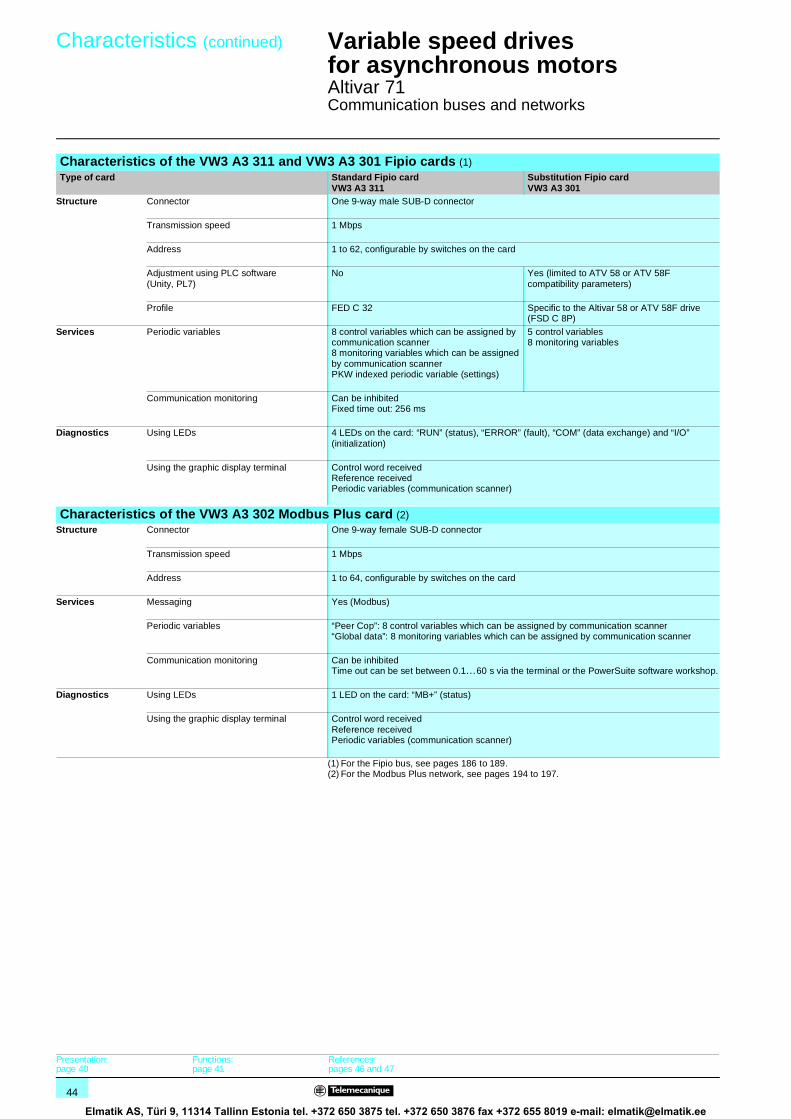
44
Characteristics (continued) 1 Variable speed drivesfor asynchronous motors 1
Altivar 71Communication buses and networks
(1) For the Fipio bus, see pages 186 to 189.(2) For the Modbus Plus network, see pages 194 to 197.
Characteristics of the VW3 A3 311 and VW3 A3 301 Fipio cards (1)Type of card Standard Fipio card
VW3 A3 311Substitution Fipio cardVW3 A3 301
Structure Connector One 9-way male SUB-D connector
Transmission speed 1 Mbps
Address 1 to 62, configurable by switches on the card
Adjustment using PLC software(Unity, PL7)
No Yes (limited to ATV 58 or ATV 58F compatibility parameters)
Profile FED C 32 Specific to the Altivar 58 or ATV 58F drive (FSD C 8P)
Services Periodic variables 8 control variables which can be assigned by communication scanner8 monitoring variables which can be assigned by communication scannerPKW indexed periodic variable (settings)
5 control variables8 monitoring variables
Communication monitoring Can be inhibitedFixed time out: 256 ms
Diagnostics Using LEDs 4 LEDs on the card: “RUN” (status), “ERROR” (fault), “COM” (data exchange) and “I/O” (initialization)
Using the graphic display terminal Control word receivedReference receivedPeriodic variables (communication scanner)
Characteristics of the VW3 A3 302 Modbus Plus card (2)Structure Connector One 9-way female SUB-D connector
Transmission speed 1 Mbps
Address 1 to 64, configurable by switches on the card
Services Messaging Yes (Modbus)
Periodic variables “Peer Cop”: 8 control variables which can be assigned by communication scanner“Global data”: 8 monitoring variables which can be assigned by communication scanner
Communication monitoring Can be inhibitedTime out can be set between 0.1…60 s via the terminal or the PowerSuite software workshop.
Diagnostics Using LEDs 1 LED on the card: “MB+” (status)
Using the graphic display terminal Control word receivedReference receivedPeriodic variables (communication scanner)
Presentation:page 40
Functions: page 41
References: pages 46 and 47
Elmatik AS, Türi 9, 11314 Tallinn Estonia tel. +372 650 3875 tel. +372 650 3876 fax +372 655 8019 e-mail: [email protected]

45
Characteristics (continued) 1 Variable speed drivesfor asynchronous motors 1
Altivar 71Communication buses and networks
Characteristics of the Profibus DP card VW3 A3 307Structure Connector One 9-way female SUB-D connector
Transmission speed 9600 bps, 19.2 Kbps, 93.75 Kbps, 187.5 Kbps, 500 Kbps, 1.5 Mbps, 3 Mbps, 6 Mbps or 12 Mbps
Address 1 to 126, configurable by switches on the card
Services Periodic variables PPO type 58 control variables which can be assigned by communication scanner8 monitoring variables which can be assigned by communication scannerPKW indexed periodic variable (settings)
Communication monitoring Can be inhibitedTime out can be set via the Profibus DP network configurator
Diagnostics Using LEDs 2 LEDs on the card: “ST” (status) and “DX” (data exchange)
Using the graphic display terminal Control word receivedReference receivedPeriodic variables (communication scanner)
Description file A single gsd file supplied on the documentation CD-ROM for the whole range. It does not contain the description of the drive parameters
Characteristics of the VW3 A3 309 DeviceNet cardStructure Connector One removable screw connector, 5 contacts at intervals of 5.08
Transmission speed 125 Kbps, 250 Kbps or 500 Kbps, configurable by switches on the card
Address 1 to 63, configurable by switches on the card
Services Periodic variables ODVA assemblies type 20, 21, 70 and 71Allen-Bradley® assemblies type 103, 104 and 105Communication scanner assemblies 100 and 101
Periodic exchange mode Inputs: Polled, Change of state, CyclicOutputs: Polled
Auto Device Replacement No
Communication monitoring Can be inhibitedTime out can be set via the DeviceNet network configurator
Diagnostics Using LEDs One two-tone LED on the card: “MNS” (status)
Using the graphic display terminal Control word receivedReference received
Description file A single eds file supplied on the documentation CD-ROM for the whole range. It contains the description of the drive parameters
Characteristics of the VW3 A3 304 INTERBUS cardStructure Connector 2 connectors: One 9-way male SUB-D and one 9-way female SUB-D
Power supply The card is powered by the drive. To ensure that the INTERBUS subscriber continues to operate during line supply failures to the power part, fit a separate power supply for the drive control part.
Drivecom profile 21
Services Messaging PCP:b Read: read a parameterb Write: write a parameterb Initiate: initialize the communication relationshipb Abort: abort the communication relationshipb Status: drive communication statusb Get-OV: read an object descriptionb Identify: identification of the card
Periodic variables 2 control variables which can be assigned by communication scanner2 monitoring variables which can be assigned by communication scanner
Communication monitoring Can be inhibitedFixed time out: 640 ms
Diagnostics Using LEDs 5 LEDs on the card: “U” (power supply), “RC” (bus input), “Rd” (bus output),“BA” (periodic data) and “TR” (messaging)
Using the graphic display terminal Control word receivedReference received
Presentation:page 40
Functions: page 41
References: pages 46 and 47
Elmatik AS, Türi 9, 11314 Tallinn Estonia tel. +372 650 3875 tel. +372 650 3876 fax +372 655 8019 e-mail: [email protected]

46
References 1 Variable speed drivesfor asynchronous motors 1
Altivar 71Communication buses and networks
Communication cards (1)Description Use Reference Weight
kgEthernetClass B20 (2)
To be connected on a Hub or Switch using a490 NTW 000 pp cable. See pages 184 and 185
VW3 A3 310 0.300
Modbus/Uni-Telway
To be connected on TSX SCA 62 subscriber socket using the VW3 A8 306 2 cable.See pages 191 and 199
VW3 A3 303 0.300
Standard Fipio To be connected using a TSX FP ACC 12 connector with a TSX FP CCpp extension cable or a TSX FP CApp drop cable. This card should be used for new installations. It is also used to replace an ATV 58 or ATV 58F drive equipped with a VW3 A58 311 card by an ATV 71 drive.To replace an ATV 58 or ATV 58F drive equipped with a VW3 58 301 card by an ATV 71 drive, use the VW3 A3 301 card (substitution).See pages 188 and 189
VW3 A3 311 0.300
Substitution Fipio
This card is also used to replace an ATV 58 or ATV 58F equipped with a VW3 A58 301 card by an ATV 71.To replace an ATV 58 or ATV 58F drive equipped with a VW3 A58 311 card by an ATV 71 drive, use the VW3 A3 311 card (standard).See pages 188 and 189
VW3 A3 301 0.300
Modbus Plus To be connected to the 990 NAD 230 00 IP 20 Modbus Plus tap using a 990 NAD 219p0 cable.See pages 196 and 197
VW3 A3 302 0.300
Profibus DP To be connected using a 490 NAD 911pp connector to Profibus cable TSX PBS CAp00 (3)
VW3 A3 307 0.300
DeviceNet The card is equipped with removable screw terminals.
VW3 A3 309 0.300
INTERBUS To be connected using cables for installation remote bus, reference 170 MCI ppp00 (3)
VW3 A3 304 0.300
(1) The Altivar 71 drive can only take one communication card. Consult the summary tables of possible drive, option and accessory combinations (see pages 86 to 89).
(2) Please consult our specialist “Ethernet TCP/IP Transparent Factory” catalogue.(3) Please consult our specialist "Modicon Premium Automation Platform - Unity & PL7"
catalogue.
TSX FP ACC12
5331
93
VW3 A3 311
5331
92
490 NAD 911 03
5331
94
Presentation:page 40
Functions: page 41
Characteristics: pages 42 to 45
Elmatik AS, Türi 9, 11314 Tallinn Estonia tel. +372 650 3875 tel. +372 650 3876 fax +372 655 8019 e-mail: [email protected]

47
References (continued) 1 Variable speed drivesfor asynchronous motors 1
Altivar 71Communication buses and networks
Connection accessoriesDescription N° Length
mUnit reference Weight
kg
Modbus busModbus splitter block10 RJ45 connectors and 1 screw terminal block
1 – LU9 GC3 0.500
Cables for Modbus bus equipped with 2 RJ45 connectors
2 0.3 VW3 A8 306 R03 0.025
1 VW3 A8 306 R10 0.060
3 VW3 A8 306 R30 0.130
Modbus T-junction boxes(with integrated cable)
3 0.3 VW3 A8 306 TF03 –
1 VW3 A8 306 TF10 –
Line terminatorFor RJ45 connector (3)
4 – VW3 A8 306 RC 0.010
Description N° Lengthm
Reference Weightkg
CANopen busCANopen adaptor for mounting on the RJ45 socket in the drive control terminals.The adaptor provides a 9-way male SUB-D connector conforming to the CANopen standard (CIA DRP 303-1).
1 – VW3 CAN A71 –
CANopen connector (4)9-way female SUB-Dwith line contactor(can be disabled).180° cable outletCAN-H, CAN-L, CAN-GND connection
2 – VW3 CAN KCDF 180T –
CANopen cables (1)Standard environments, fixed installation, LSZH (Low Smoke, Zero Halogen)
3 50 TSX CAN CA 50 –
100 TSX CAN CA 100 –
300 TSX CAN CA 300 –
CANopen cables (1)Standard environments, fixed installation, UL certification, flame retardant (IEC 60332-2)
3 50 TSX CAN CB 50 –
100 TSX CAN CB 100 –
300 TSX CAN CB 300 –
CANopen cables (1)Harsh environments, mobile installation, LSZH (Low Smoke, Zero Halogen), resistant to chemicals and solder splashes
3 50 TSX CAN CD 50 –
100 TSX CAN CD 100 –
300 TSX CAN CD 300 –
(1) Please consult our specialist "Modicon Premium Automation Platform - Unity & PL7" and "Modicon TSX Micro Automation Platform - PL7" catalogues.
(2) Cable depending on the type of controller or PLC.(3) Sold in lots of 2.(4) On drives ATV 71HpppM3, ATV 71HD11M3X, HD15M3X,ATV 71H075N4… HD18N4, this
connector can be replaced by the TSX CAN KCDF 180T connector.
4
22(2)
21 23
ATV 71
3 4
3 3
Example of Modbus diagram, connections via splitter blocks and RJ45 connectors
Premium (1)
5331
95M
odbu
s bu
s
VW3 CAN A71
533
196
(2)
12
3
Example of CANopen diagram
Premium (1)
5331
96C
AN
open
bus ATV 71
Presentation:page 40
Functions: pages 41
Characteristics: pages 42 to 45
Elmatik AS, Türi 9, 11314 Tallinn Estonia tel. +372 650 3875 tel. +372 650 3876 fax +372 655 8019 e-mail: [email protected]
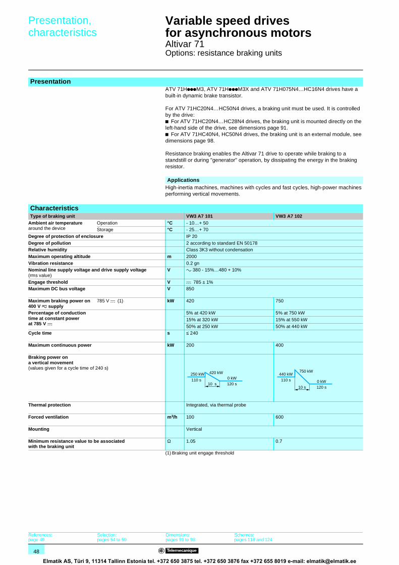
48
Presentation, characteristics 1
Variable speed drivesfor asynchronous motors 1
Altivar 71Options: resistance braking units
ATV 71HpppM3, ATV 71HpppM3X and ATV 71H075N4…HC16N4 drives have a built-in dynamic brake transistor.
For ATV 71HC20N4…HC50N4 drives, a braking unit must be used. It is controlled by the drive:b For ATV 71HC20N4…HC28N4 drives, the braking unit is mounted directly on the left-hand side of the drive, see dimensions page 91.b For ATV 71HC40N4, HC50N4 drives, the braking unit is an external module, see dimensions page 98.
Resistance braking enables the Altivar 71 drive to operate while braking to a standstill or during "generator" operation, by dissipating the energy in the braking resistor.
(1) Braking unit engage threshold
Presentation
ApplicationsHigh-inertia machines, machines with cycles and fast cycles, high-power machines performing vertical movements.
CharacteristicsType of braking unit VW3 A7 101 VW3 A7 102
Ambient air temperaturearound the device
Operation °C - 10…+ 50Storage °C - 25…+ 70
Degree of protection of enclosure IP 20
Degree of pollution 2 according to standard EN 50178Relative humidity Class 3K3 without condensation
Maximum operating altitude m 2000
Vibration resistance 0.2 gnNominal line supply voltage and drive supply voltage(rms value)
V a 380 - 15%…480 + 10%
Engage threshold V c 785 ± 1%Maximum DC bus voltage V 850
Maximum braking power on 400 V z supply
785 V c (1) kW 420 750
Percentage of conductiontime at constant powerat 785 V c
5% at 420 kW 5% at 750 kW
15% at 320 kW 15% at 550 kW
50% at 250 kW 50% at 440 kWCycle time s ≤ 240
Maximum continuous power kW 200 400
Braking power ona vertical movement(values given for a cycle time of 240 s)
Thermal protection Integrated, via thermal probe
Forced ventilation m3/h 100 600
Mounting Vertical
Minimum resistance value to be associatedwith the braking unit
Ω 1.05 0.7
250 kW
110 s
420 kW0 kW120 s10 s
440 kW
110 s
750 kW
0 kW120 s10 s
References:page 49
Selection:pages 54 to 59
Dimensions:pages 91 to 98
Schemes:pages 118 and 124
Elmatik AS, Türi 9, 11314 Tallinn Estonia tel. +372 650 3875 tel. +372 650 3876 fax +372 655 8019 e-mail: [email protected]

49
References 1 Variable speed drivesfor asynchronous motors 1
Altivar 71Options: resistance braking units
Note: To increase the braking power, several resistors can be mounted in parallel on the same braking unit. In this case, do not forget to take account of the minimum resistance value on each unit.
Braking unitsSupply voltage: 380…480 V 50/60 HzFor drives Power Loss Cable (drive-
braking unit)Cable (braking unit-resistors)
Reference Weight
Continuous Max. Continuous power
Cross-section
Max. length
Cross-section
Max. length
kW kW W mm2 m mm2 m kgATV 71HC20N4… HC28N4
200 420 550 – – 2 x 95 50 VW3 A7 101 30.000Internal connections
ATV 71HC31N4…HC50N4
400 750 750 2 x 150 1 2 x 150 50 VW3 A7 102 80.000
Presentation:page 48
Characteristics:page 48
Selection:pages 54 to 59
Dimensions:pages 91 to 98
Schemes:pages 118 and 124
Elmatik AS, Türi 9, 11314 Tallinn Estonia tel. +372 650 3875 tel. +372 650 3876 fax +372 655 8019 e-mail: [email protected]
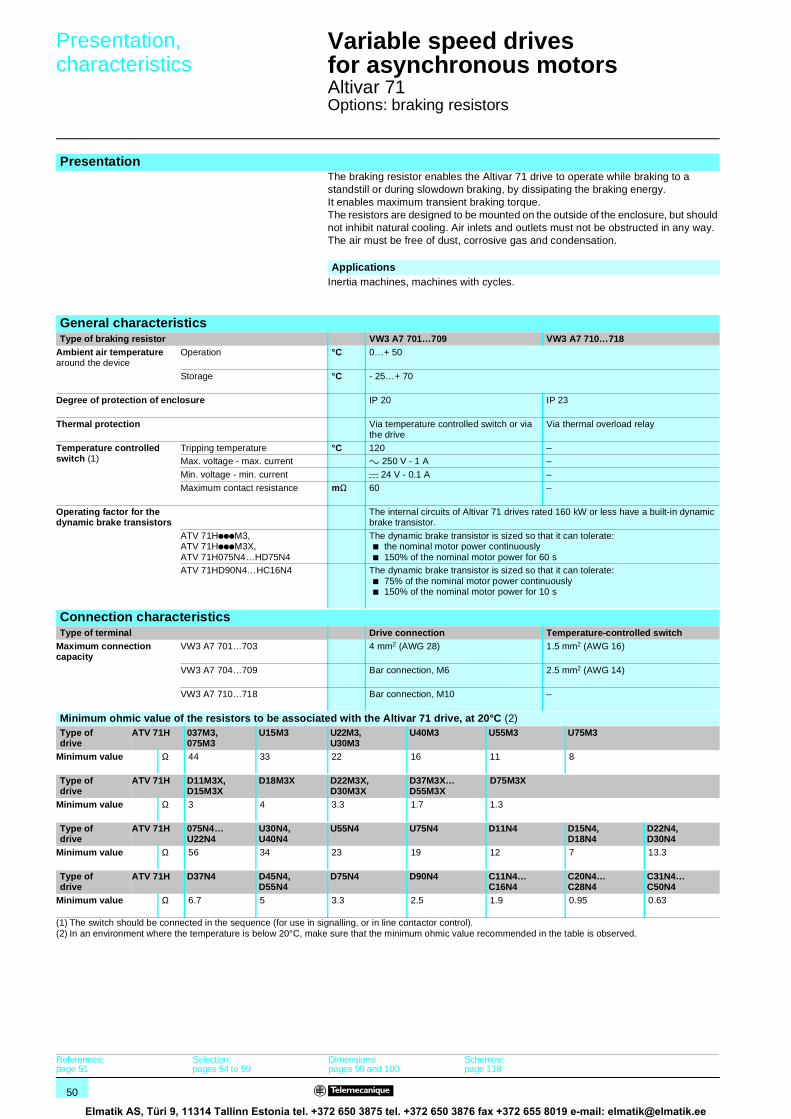
50
Presentation, characteristics 1
Variable speed drivesfor asynchronous motors 1
Altivar 71Options: braking resistors
The braking resistor enables the Altivar 71 drive to operate while braking to a standstill or during slowdown braking, by dissipating the braking energy.It enables maximum transient braking torque.The resistors are designed to be mounted on the outside of the enclosure, but should not inhibit natural cooling. Air inlets and outlets must not be obstructed in any way. The air must be free of dust, corrosive gas and condensation.
(1) The switch should be connected in the sequence (for use in signalling, or in line contactor control).(2) In an environment where the temperature is below 20°C, make sure that the minimum ohmic value recommended in the table is observed.
Presentation
ApplicationsInertia machines, machines with cycles.
General characteristicsType of braking resistor VW3 A7 701…709 VW3 A7 710…718
Ambient air temperaturearound the device
Operation °C 0…+ 50
Storage °C - 25…+ 70
Degree of protection of enclosure IP 20 IP 23
Thermal protection Via temperature controlled switch or via the drive
Via thermal overload relay
Temperature controlled switch (1)
Tripping temperature °C 120 –Max. voltage - max. current a 250 V - 1 A –
Min. voltage - min. current c 24 V - 0.1 A –
Maximum contact resistance mΩ 60 –
Operating factor for thedynamic brake transistors
The internal circuits of Altivar 71 drives rated 160 kW or less have a built-in dynamic brake transistor.
ATV 71HpppM3, ATV 71HpppM3X, ATV 71H075N4…HD75N4
The dynamic brake transistor is sized so that it can tolerate: b the nominal motor power continuouslyb 150% of the nominal motor power for 60 s
ATV 71HD90N4…HC16N4 The dynamic brake transistor is sized so that it can tolerate: b 75% of the nominal motor power continuouslyb 150% of the nominal motor power for 10 s
Connection characteristicsType of terminal Drive connection Temperature-controlled switch
Maximum connection capacity
VW3 A7 701…703 4 mm2 (AWG 28) 1.5 mm2 (AWG 16)
VW3 A7 704…709 Bar connection, M6 2.5 mm2 (AWG 14)
VW3 A7 710…718 Bar connection, M10 –
Minimum ohmic value of the resistors to be associated with the Altivar 71 drive, at 20°C (2)Type ofdrive
ATV 71H 037M3,075M3
U15M3 U22M3,U30M3
U40M3 U55M3 U75M3
Minimum value Ω 44 33 22 16 11 8
Type ofdrive
ATV 71H D11M3X, D15M3X
D18M3X D22M3X,D30M3X
D37M3X…D55M3X
D75M3X
Minimum value Ω 3 4 3.3 1.7 1.3
Type ofdrive
ATV 71H 075N4…U22N4
U30N4, U40N4
U55N4 U75N4 D11N4 D15N4,D18N4
D22N4, D30N4
Minimum value Ω 56 34 23 19 12 7 13.3
Type ofdrive
ATV 71H D37N4 D45N4, D55N4
D75N4 D90N4 C11N4…C16N4
C20N4…C28N4
C31N4…C50N4
Minimum value Ω 6.7 5 3.3 2.5 1.9 0.95 0.63
References:page 51
Selection:pages 54 to 59
Dimensions:pages 99 and 100
Schemes:page 118
Elmatik AS, Türi 9, 11314 Tallinn Estonia tel. +372 650 3875 tel. +372 650 3876 fax +372 655 8019 e-mail: [email protected]

51
References 1 Variable speed drivesfor asynchronous motors 1
Altivar 71Options: braking resistors
Braking resistorsFor drives Ohmic value
at 20°CAverage power available at 50°C (1)
Reference Weight
Ω kW kg
Supply voltage: 200…240 V 50/60 HzATV 71H037M3, H075M3 100 0.05 VW3 A7 701 1.900
ATV 71HU15M3, HU22M3 60 0.1 VW3 A7 702 2.400
ATV 71HU30M3, HU40M3 28 0.2 VW3 A7 703 3.500
ATV 71HU55M3, HU75M3 15 1 VW3 A7 704 11.000
ATV 71HD11M3X 10 1 VW3 A7 705 11.000
ATV 71HD15M3X 8 1 VW3 A7 706 11.000
ATV 71HD18M3X, HD22M3X 5 1 VW3 A7 707 11.000
ATV 71HD30M3X 4 1 VW3 A7 708 11.000
ATV 71HD37M3X, HD45M3X 2.5 1 VW3 A7 709 11.000
ATV 71HD55M3X 1.8 15.3 VW3 A7 713 50.000
ATV 71HD75M3X 1.4 20.9 VW3 A7 714 63.000
Supply voltage: 380…480 V 50/60 HzATV 71H075N4…HU40N4 100 0.05 VW3 A7 701 1.900
ATV 71HU55N4, HU75N4 60 0.1 VW3 A7 702 2.400
ATV 71HD11N4, HD15N4 28 0.2 VW3 A7 703 3.500
ATV 71HD18N4…HD30N4 15 1 VW3 A7 704 11.000
ATV 71HD37N4 10 1 VW3 A7 705 11.000
ATV 71HD45N4…HD75N4 5 1 VW3 A7 707 11.000
ATV 71HD90N4 2.75 25 VW3 A7 710 80.000
ATV 71HC11N4, HC13N4 2.1 37 VW3 A7 711 86.000
ATV 71HC16N4 2.1 44 VW3 A7 712 104.000
ATV 71HC20N4 1.05 56 VW3 A7 715 136.000
ATV 71HC25N4, HC28N4 1.05 75 VW3 A7 716 172.000
ATV 71HC31N4, HC40N4 0.7 112 VW3 A7 717 266.000
ATV 71HC50N4 0.7 150 VW3 A7 718 350.000
(1) Operating factor for resistors: The value of the average power that can be dissipated at 50°C from the resistor into the casing is determined for an operating factor during braking that corresponds to the majority of normal applications.For VW3 A7 701…709:- 2 s braking with 0.6 Tn braking torque for a 40 s cycle- 0.8 s braking with 1.5 Tn braking torque for a 40 s cycleFor VW3 A7 710…718:- 10 s braking with 2 Tn braking torque for a 30 s cycle
Presentation:page 50
Characteristics:page 50
Selection:pages 54 to 59
Dimensions:pages 99 and 100
Schemes:page 118
Elmatik AS, Türi 9, 11314 Tallinn Estonia tel. +372 650 3875 tel. +372 650 3876 fax +372 655 8019 e-mail: [email protected]

52
Presentation, characteristics 1
Variable speed drivesfor asynchronous motors 1
Altivar 71Options: hoist resistors
The hoist resistor is a braking resistor which enables the Altivar 71 drive to operate while braking to a standstill or during slowdown braking, by dissipating the braking energy.The resistors are designed to be mounted on the outside of the enclosure, but should not inhibit natural cooling. Air inlets and outlets must not be obstructed in any way.The air must be free of dust, corrosive gas and condensation.They enable maximum transient braking torque.
(1) For ATV 71HC20N4…HC50N4 drives, a braking unit must be used, see page 48.(2) In an environment where the temperature is below 20°C, make sure that the minimum ohmic value recommended in the table is observed.
Presentation
ApplicationsMachines performing vertical movements, machines with fast cycles, high-inertia machines.
General characteristicsType of hoist resistor VW3 A7 801 VW3 A7 802…A7 808 VW3 A7 809…A7 817
Ambient air temperaturearound the device
Operation °C 0…+ 50
Storage °C - 25…+ 75 - 25…+ 65
Degree of protection of enclosure IP 23 if horizontal mountingIP 20 in other cases
IP 23
Thermal protection Via thermal overload relay
Operating factor for thedynamic brake transistors
The internal circuits of Altivar 71 drives rated 160 kW or less have a built-in dynamic brake transistor.
ATV 71HpppM3, ATV 71HpppM3X, ATV 71H075N4…HD75N4
The dynamic brake transistor is sized so that it can tolerate: b the nominal motor power continuouslyb 150% of the nominal motor power for 60 s
ATV 71HD90N4…HC50N4 (1) The dynamic brake transistor is sized so that it can operate on a 240 s cycle at: b 88% of the nominal motor power for 50% of the cycle timeb 150% of the nominal motor power for 5% of the cycle
Connection characteristicsMaximum connection capacity
VW3 A7 801 Bar connection, M6
VW3 A7 802…817 Bar connection, M10
Minimum ohmic value of the resistors to be associated with the Altivar 71 drive, at 20°C (2)Type ofdrive
ATV 71H 037M3,075M3
U15M3 U22M3,U30M3
U40M3 U55M3 U75M3
Minimum value Ω 44 33 22 16 11 8
Type ofdrive
ATV 71H D11M3X, D15M3X
D18M3X D22M3X,D30M3X
D37M3X…D55M3X
D75M3X
Minimum value Ω 3 4 3.3 1.7 1.3
Type ofdrive
ATV 71H 075N4…U22N4
U30N4, U40N4
U55N4 U75N4 D11N4 D15N4,D18N4
D22N4, D30N4
Minimum value Ω 56 34 23 19 12 7 13.3
Type ofdrive
ATV 71H D37N4 D45N4, D55N4
D75N4 D90N4 C11N4…C16N4
C20N4…C28N4
C31N4…C50N4
Minimum value Ω 6.7 5 3.3 2.5 1.9 0.95 0.63
References:page 53
Selection:pages 54 to 59
Dimensions:page 101
Schemes:page 118
Elmatik AS, Türi 9, 11314 Tallinn Estonia tel. +372 650 3875 tel. +372 650 3876 fax +372 655 8019 e-mail: [email protected]

53
References 1 Variable speed drivesfor asynchronous motors 1
Altivar 71Options: hoist resistors
(1) Operating factor for hoist resistors: the value of the average power that can be dissipated at 50°C from the resistor is determined by an operating factor during braking.For VW3 A7 801…808:- 100 s braking with 1 Tn braking torque for a 200 s cycle- 20 s braking with 1.6 Tn braking torque for a 200 s cycleFor VW3 A7 809…817:- 110 s braking with 1.25 Tn braking torque for a 240 s cycle- 10 s braking with 2 Tn braking torque for a 240 s cycle
Hoist resistorsFor drives Ohmic value
at 20°CAverage power available at 50°C (1)
Reference Weight
Ω kW kg
Supply voltage: 200…240 V 50/60 HzATV 71H037M3, H075M3 100 1.6 VW3 A7 801 6.000
ATV 71HU15M3 60 5.6 VW3 A7 802 21.000
ATV 71HU22M3…HU40M3 24.5 9.8 VW3 A7 803 28.000
ATV 71HU55M3, HU75M3 14 22.4 VW3 A7 804 54.000
ATV 71HD11M3X, HD15M3X 8.1 44 VW3 A7 805 92.000
ATV 71HD18M3X 4.2 62 VW3 A7 806 126.000
ATV 71HD22M3X, HD30M3X 3.5 19.5 VW3 A7 807 51.000
ATV 71HD37M3X, HD45M3X 1.85 27.4 VW3 A7 808 94.000
ATV 71HD55M3X 1.8 30.6 VW3 A7 809 103.000
ATV 71HD75M3X 1.4 44 VW3 A7 810 119.000
Supply voltage: 380…480 V 50/60 HzATV 71H075N4…HU22N4 100 1.6 VW3 A7 801 6.000
ATV 71HU30N4…HU55N4 60 5.6 VW3 A7 802 21.000
ATV 71HU75N4, HD11N4 24.5 9.8 VW3 A7 803 28.000
ATV 71HD15N4…HD30N4 14 22.4 VW3 A7 804 54.000
ATV 71HD37N4…HD55N4 8.1 44 VW3 A7 805 92.000
ATV 71HD75N4 4.2 62 VW3 A7 806 126.000
ATV 71HD90N4 2.75 56 VW3 A7 811 130.000
ATV 71HC11N4, HC13N4 2.1 75 VW3 A7 812 181.000
ATV 71HC16N4 2.1 112 VW3 A7 813 250.000
ATV 71HC20N4 1.05 112 VW3 A7 814 280.000
ATV 71HC25N4, HC28N4 1.05 150 VW3 A7 815 362.000
ATV 71HC31N4, HC40N4 0.7 225 VW3 A7 816 543.000
ATV 71HC50N4 0.7 330 VW3 A7 817 642.000
Presentation:page 52
Characteristics:page 52
Selection:pages 54 to 59
Dimensions:page 101
Schemes:page 118
Elmatik AS, Türi 9, 11314 Tallinn Estonia tel. +372 650 3875 tel. +372 650 3876 fax +372 655 8019 e-mail: [email protected]

54
Selection 1 Variable speed drivesfor asynchronous motors 1
Altivar 71Options: braking units and resistors
Calculating the various braking powers makes it possible to determine the braking unit and the braking resistor.
Calculating the braking time from the inertia
Determining the braking unit and resistor
Presentation of the two main types of operation: A and B
A The braking power during deceleration is characterized by a peak power obtained at the start of deceleration, which decreases to 0 in proportion with the speed.Example: Stopping centrifuges, translational movement, change of direction, etc
B Braking power at constant speed n2.Example: Vertical downward movement, motor/generator test bench, gravity conveyors, etc.
n1 Motor speed [rpm]
n2 Motor speed during deceleration [rpm]Tl Load torque [Nm]
Tb Braking torque [Nm]
Peak braking power [W]
Average braking power during tb [W]
tb Braking time [s]
Note: Both these types of operation can be combined.
Type A operation
P
b
n
t
t
t0
n1
Pbraking
Pb
Pb
tb
tb
tb
TTl
Tb
n
t
t
t
1
2
0
-n
+n
Pbraking
Pb
Tl
tb
P b
Pb
tbJ ω⋅
Tb Tr+------------------= ω 2π n⋅
60--------------= Tb
ΣJ n1 n2( )⋅9,55 tb⋅
----------------------------------= P
bTb n1⋅9,55----------------=
PbP
b
2------=
Tb Motor braking torque [Nm]
∑J Total inertia applied to the motor [kgm2]n1 Motor speed ahead of gearbox [rpm]
n2 Motor speed after gearbox [rpm]
tb Braking time [s]Peak braking power [W]
Average braking power during time tb [W]
Tr Resistive torque [Nm]
n 2n 1
1
2i =
nn
2i
Motor Gearbox
Machine
JmachineJapplied
∑ J = Jmotor +Japplied
P b
Pb
Presentation:page 52
Characteristics:page 52
References:pages 49 and 51
Dimensions:pages 91 to 101
Schemes:page 118
Elmatik AS, Türi 9, 11314 Tallinn Estonia tel. +372 650 3875 tel. +372 650 3876 fax +372 655 8019 e-mail: [email protected]

55
Selection (continued) 1 Variable speed drivesfor asynchronous motors 1
Altivar 71Options: braking units and resistors
The braking unit is selected taking the following into account:b the continuous powerb the average braking power during downward movementb the peak power Depending on these elements, select the braking unit according to the characteristics on page 48.The braking resistor is selected taking account of the same elements listed above but with the addition of a check to ensure that the resistance value will allow the peak
power to be exceeded .
Note: The resistance value must always be greater than or equal to the values given in the tables on pages 50 and 52.
Operating type B1 Braking power of a load moving horizontally with constant deceleration (eg.: carriage)
W Kinetic energy [Joule] m Weight [kg]
v Speed [m/s]
tb Braking time [s]Peak braking power [W]
Average braking power during time tb [W] 2 Braking power for an active load (eg.: test bench) Tb Braking torque [Nm]
n Motor speed [rpm]
g Acceleration 9.81 m/s2
a Deceleration [m/s2] 3 Braking power for a downward vertical movement
v Linear downward speed [m/s] J Moment of inertia [kgms2]
ω Angular speed [rad/s]
tb Downward stopping time [s]
All the braking power calculations are only true if it is assumed that there are no losses (η = 1) and that there is no resistive torque.To be even more precise, the following must be considered:b the losses and the resistive torque of the system, which reduce the necessary braking powerb the driving torque (the wind, for example) which increases the braking power.
The required braking power is calculated as follows:Maximum actual braking power [W]
Continuous actual braking power [W]
ηtotal Total efficiencyPload Braking power connected with the resistive or
driving torque (not taken into account in the calculation). Pload can be positive or negative.
[W]
ηdrive Drive efficiency = 0.98ηmec Mechanical efficiency
ηmot Motor efficiency
For braking, the value of the braking resistor is selected to match the required power and the braking cycle.
Udc Braking unit engage threshold [V] In general:
T Cycle time [s]Upward braking power, therefore zero [W] Continuous power is obtained by taking the operating cycle into account.
t0 Rise time [s]
Average braking power during downward movement
[W]
t1 Downward movement time [1]
Peak braking power [W]
Average power during braking to a standstill [W]
t2 Standstill braking time [s]
Pcontinuous
[W]
W m v2⋅2
---------------= PbWtb-----= P
b Pb 2⋅=
P b
Pb
PbTb n⋅9,55--------------=
Pb m g v⋅ ⋅= P
b m g a+( ) v J ω2⋅tb
--------------+⋅ ⋅= ω 2π n⋅60--------------=
P b R
P
bR Pb Pload( ) η2×= total
η total ηmec ηmot 0,98××=
PbR Pb Pload( ) η2×= totalPb R
P
bRU2dc
R-------------- R⇒ U2dc
P
bR
--------------= =
Pb 0
t1t0
^
_
_
_
t2
Pb0
Pb1
Pb
Pb2
tc
Pb 1
P b
Pb 2
Pb0 t0 Pb1 t1 Pb2 t2×+×+×T
-------------------------------------------------------------------------=
Pb1
Pb2
P
b
R U2dc
P b
--------------=
Presentation:page 52
Characteristics:page 52
References:pages 49 and 51
Dimensions:pages 91 to 101
Schemes:page 118
Elmatik AS, Türi 9, 11314 Tallinn Estonia tel. +372 650 3875 tel. +372 650 3876 fax +372 655 8019 e-mail: [email protected]

56
Selection (continued) 1 Variable speed drivesfor asynchronous motors 1
Altivar 71Characteristics curves for resistors
Example of using characteristics curvesVW3 A7 710 (P continuous = 25 kW) for 2.75 Ω at 20°C
Example of using curves:
Point A For a 200 s cycle, the resistance of 2.75 Ωaccepts an overload of 7 x 25 kW (continuouspower) for 24 s, ie. braking 175 kW every 200 s.
Point B For a 120 s cycle, the resistance of 2.75 Ωaccepts an overload of 5 x 25 kW (continuouspower) for 20 s, ie. braking 125 kW every 120 s.
Point C For a 60 s cycle, the resistance of 2.75 Ωaccepts an overload of 5 x 25 kW (continuouspower) for 10 s, ie. braking 125 kW every 60 s.
Braking resistorsVW3 A7 701 (P continuous = 0.05 kW) VW3 A7 702 (P continuous = 0.1 kW)
VW3 A7 703 (P continuous = 0.2 kW) VW3 A7 704…709 (P continuous = 1 kW)
10
15
20
25
30
5
7
00 5025 75
A
BC
Coef.Pmax.Pav.
0
10
2
20
30
40
50
0 5 10 15 20 t (s)
Coef.Pmax.Pav.
0
10
2
20
30
40
50
0 5 10 15 20 t (s)
Coef.Pmax.Pav.
0
10
2
20
30
40
50
0 5 10 15 20 t (s)
Coef.Pmax.Pav.
0
10
2
20
30
40
50
0 5 10 15 20 t (s)
Coef.Pmax.Pav.
P max/P av (40 s cycle)P max/P av (60 s cycle)P max/P av (120 s cycle)P max/P av (200 s cycle)
Presentation:page 52
Characteristics:page 52
References:page 51
Dimensions:pages 99 and 100
Schemes:page 118
Elmatik AS, Türi 9, 11314 Tallinn Estonia tel. +372 650 3875 tel. +372 650 3876 fax +372 655 8019 e-mail: [email protected]

57
Selection (continued) 1 Variable speed drivesfor asynchronous motors 1
Altivar 71Characteristics curves for resistors
Braking resistors (continued)VW3 A7 710 (P continuous = 25 kW) VW3 A7 711 (P continuous = 37 kW)
VW3 A7 712 (P continuous = 44 kW) VW3 A7 713 (P continuous = 15.3 kW)
VW3 A7 714 (P continuous = 20.9 kW) VW3 A7 715 (P continuous = 56 kW)
10
15
2025
30
35
40
45
50
5
0t (s)0 50 100 150 20025 75 125 175
Coef.Pmax.Pav.
t (s)0 50 100 150 200
15
10
20
30
25
5
025 75 125 175
Coef.Pmax.Pav.
t (s)0 50 100 150 200
15
10
20
35
30
25
5
025 75 125 175
Coef.Pmax.Pav.
10
15
2025
30
35
40
45
50
5
0t (s)0 50 100 150 20025 75 125 175
Coef.Pmax.Pav.
10
15
2025
30
35
40
45
50
5
0t (s)0 50 100 150 20025 75 125 175
Coef.Pmax.Pav.
10
15
20
25
30
35
40
45
5
0t (s)0 50 100 150 20025 75 125 175
Coef.Pmax.Pav.
P max/P av (60 s cycle)P max/P av (120 s cycle)P max/P av (200 s cycle)
Presentation:page 52
Characteristics:page 52
References:page 51
Dimensions:pages 99 and 100
Schemes:page 118
Elmatik AS, Türi 9, 11314 Tallinn Estonia tel. +372 650 3875 tel. +372 650 3876 fax +372 655 8019 e-mail: [email protected]

58
Selection (continued) 1 Variable speed drivesfor asynchronous motors 1
Altivar 71Characteristics curves for resistors
Braking resistors (continued)VW3 A7 716 (P continuous = 75 kW) VW3 A7 717 (P continuous = 112 kW)
VW3 A7 718 (P continuous = 150 kW)
10
15
20
25
30
35
40
45
5
0t (s)0 50 100 150 20025 75 125 175
Coef.Pmax.Pav.
10
15
20
25
30
35
40
5
0t (s)0 50 100 150 20025 75 125 175
Coef.Pmax.Pav.
10
15
20
25
30
35
40
45
5
0t (s)0 50 100 150 20025 75 125 175
Coef.Pmax.Pav.
P max/P av (60 s cycle)P max/P av (120 s cycle)P max/P av (200 s cycle)
Presentation:page 52
Characteristics:page 52
References:page 51
Dimensions:pages 99 and 100
Schemes:page 118
Elmatik AS, Türi 9, 11314 Tallinn Estonia tel. +372 650 3875 tel. +372 650 3876 fax +372 655 8019 e-mail: [email protected]
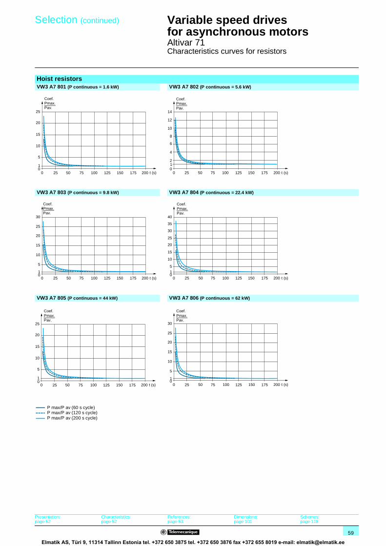
59
Selection (continued) 1 Variable speed drivesfor asynchronous motors 1
Altivar 71Characteristics curves for resistors
Hoist resistorsVW3 A7 801 (P continuous = 1.6 kW) VW3 A7 802 (P continuous = 5.6 kW)
VW3 A7 803 (P continuous = 9.8 kW) VW3 A7 804 (P continuous = 22.4 kW)
VW3 A7 805 (P continuous = 44 kW) VW3 A7 806 (P continuous = 62 kW)
t (s)0 50 100 150 200
15
10
20
25
5
10
25 75 125 175
Coef.Pmax.Pav.
1
t (s)0 50 100 150 200
6
8
10
12
14
2
4
025 75 125 175
Coef.Pmax.Pav.
t (s)0 50 100 150 200
15
10
20
25
30
5
10
25 75 125 175
Coef.Pmax.Pav.
t (s)0 50 100 150 200
15
10
20
25
30
35
40
510
25 75 125 175
Coef.Pmax.Pav.
t (s)0 50 100 150 200
15
10
20
25
5
10
25 75 125 175
Coef.Pmax.Pav.
t (s)0 50 100 150 200
15
10
20
25
30
5
10
25 75 125 175
Coef.Pmax.Pav.
P max/P av (60 s cycle)P max/P av (120 s cycle)P max/P av (200 s cycle)
Presentation:page 52
Characteristics:page 52
References:page 53
Dimensions:page 101
Schemes:page 118
Elmatik AS, Türi 9, 11314 Tallinn Estonia tel. +372 650 3875 tel. +372 650 3876 fax +372 655 8019 e-mail: [email protected]

60
Selection (continued) 1 Variable speed drivesfor asynchronous motors 1
Altivar 71Characteristics curves for resistors
Hoist resistors (continued)VW3 A7 807 (P continuous = 19.5 kW) VW3 A7 808 (P continuous = 27.4 kW)
VW3 A7 809 (P continuous = 30.6 kW) VW3 A7 810 (P continuous = 44 kW)
VW3 A7 811 (P continuous = 56 kW) VW3 A7 812 (P continuous = 75 kW)
t (s)0 50 100 150 200
15
10
20
25
30
35
40
510
25 75 125 175
Coef.Pmax.Pav.
t (s)0 50 100 150 200
10
1
20
30
40
50
60
25 75 125 175
Coef.Pmax.Pav.
10
15
2025
30
35
40
45
50
5
0t (s)0 50 100 150 20025 75 125 175
Coef.Pmax.Pav.
10
15
20
25
30
35
40
45
5
0t (s)0 50 100 150 20025 75 125 175
Coef.Pmax.Pav.
10
15
20
25
30
35
40
5
0t (s)0 50 100 150 20025 75 125 175
Coef.Pmax.Pav.
10
15
20
25
30
35
40
45
5
0t (s)0 50 100 150 20025 75 125 175
Coef.Pmax.Pav.
P max/P av (60 s cycle)P max/P av (120 s cycle)P max/P av (200 s cycle)
Presentation:page 52
Characteristics:page 52
References:page 53
Dimensions:page 101
Schemes:page 118
Elmatik AS, Türi 9, 11314 Tallinn Estonia tel. +372 650 3875 tel. +372 650 3876 fax +372 655 8019 e-mail: [email protected]

61
Selection (continued) 1 Variable speed drivesfor asynchronous motors 1
Altivar 71Characteristics curves for resistors
Hoist resistors (continued)VW3 A7 813 (P continuous = 112 kW) VW3 A7 814 (P continuous = 112 kW)
VW3 A7 815 (P continuous = 150 kW) VW3 A7 816 (P continuous = 225 kW)
VW3 A7 817 (P continuous = 330 kW)
10
15
20
25
30
35
40
5
0t (s)0 50 100 150 20025 75 125 175
Coef.Pmax.Pav.
10
15
20
25
30
35
40
45
5
0t (s)0 50 100 150 20025 75 125 175
Coef.Pmax.Pav.
10
15
20
25
30
35
40
45
5
0t (s)0 50 100 150 20025 75 125 175
Coef.Pmax.Pav.
10
15
20
25
30
35
40
45
5
0t (s)0 50 100 150 20025 75 125 175
Coef.Pmax.Pav.
10
15
20
25
30
35
40
5
0t (s)0 50 100 150 20025 75 125 175
Coef.Pmax.Pav.
P max/P av (60 s cycle)P max/P av (120 s cycle)P max/P av (200 s cycle)
Presentation:page 52
Characteristics:page 52
References:page 53
Dimensions:page 101
Schemes:page 118
Elmatik AS, Türi 9, 11314 Tallinn Estonia tel. +372 650 3875 tel. +372 650 3876 fax +372 655 8019 e-mail: [email protected]

62
Presentation,applications,characteristics 1
Variable speed drivesfor asynchronous motors 1
Altivar 71Options: network braking units
The network braking unit can be used to restore the following to the line supply:b the energy from the motorb the energy from the motors controlled by several drives connected on the same DC bus
Braking on a driving load:b vertical movementsb escalatorsb etc
Presentation
L1
L2
L3
PA/+
PC/–
Network braking unitAltivar 71
Applications
General characteristicsDegree of protection IP 20
Maximum relative humidity Class F humidity without condensation 5…85%
Ambient air temperaturearound the device
Operation °C 5…+ 40 without deratingUp to 55°C with current derating of 3% per °C above 40°C
Storage °C - 25…+ 55
Maximum operating altitude m 1000 without derating1000…4000 derating the current by 5% per additional 1000 m
Electrical characteristicsType of module VW3 A7 201…212 VW3 A7 231…241
Supply voltage V a 400 a 460
Nominal voltage ± 10% V a 380…415 a 440…480
Operating frequency Hz 40…60 ± 10 %
Overload capacity A 1.2 x maximum current (Irms)
Efficiency 97% (3% of thermal losses)
Power factor 1
Fundamental frequency component 0.7…0.95
Connection characteristicsMaximum connectioncapacity
VW3 A7 201 25 mm2, connected on a bar, M5
VW3 A7 202…205,VW3 A7 231, 232
35 mm2, connected on a bar, M6
VW3 A7 206…209,VW3 A7 233…238
95 mm2, connected on a bar, M8
VW3 A7 210…212,VW3 A7 239…241
150 mm2, connected on a bar, M10
References:page 63
Selection:pages 64 and 65
Dimensions:pages 102 and 103
Schemes:page 123
Elmatik AS, Türi 9, 11314 Tallinn Estonia tel. +372 650 3875 tel. +372 650 3876 fax +372 655 8019 e-mail: [email protected]

63
References 1 Variable speed drivesfor asynchronous motors 1
Altivar 71Options: network braking units
Line voltage: a 400 VMaximum currentIrms
Continuous braking power
CL fuses Reference Weight
a c a aA A kW A V kg
11 13 7 20 660 VW3 A7 201 20.000
20 24 13 30 690 VW3 A7 202 25.000
32 38 11 50 690 VW3 A7 203 26.000
48 58 21.5 80 690 VW3 A7 204 30.000
65 78 26 100 690 VW3 A7 205 32.000
102 123 32 160 660 VW3 A7 206 43.000
130 157 38 200 660 VW3 A7 207 48.000
195 236 38 315 660 VW3 A7 208 52.000
231 279 86 350 660 VW3 A7 209 90.000
289 350 120 400 1000 VW3 A7 210 100.000
360 433 135 500 1000 VW3 A7 211 115.000
500 600 200 630 1000 VW3 A7 212 125.000
Line voltage: a 460 VMaximum currentIrms
Continuous braking power
CL fuses Reference Weight
a c a aA A kW A V kg
28 33 – 50 690 VW3 A7 231 26.000
41 50 21.5 80 690 VW3 A7 232 30.000
57 69 26 100 690 VW3 A7 233 36.000
88 107 32 160 660 VW3 A7 234 43.000
113 137 38 200 660 VW3 A7 235 48.000
138 166 38 250 660 VW3 A7 236 48.000
157 189 38 250 660 VW3 A7 237 50.000
176 212 38 315 660 VW3 A7 238 90.000
201 243 86 315 660 VW3 A7 239 100.000
289 346 120 500 1000 VW3 A7 240 105.000
500 600 240 630 1000 VW3 A7 241 125.000
Presentation:page 62
Selection:pages 64 and 65
Dimensions:pages 102 and 103
Schemes:page 123
Elmatik AS, Türi 9, 11314 Tallinn Estonia tel. +372 650 3875 tel. +372 650 3876 fax +372 655 8019 e-mail: [email protected]

64
Selection 1 Variable speed drivesfor asynchronous motors 1
Altivar 71Characteristic curves
(1) Power indicated for a temperature of 35°C.
Example of how to use characteristic curvesVW3 A7 204, A7 232 (Continuous braking power = 21.5 kW) (1)
Example of how to use the curves:
Required braking power of 27 kW.The intersection point between the braking time and the time between 2 braking operations must be on or below the relevant curve.
Point A For a braking time of 2 minutes, there must be at least50 seconds between 2 braking operations.
Network braking unitsVW3 A7 204, A7 232 (Continuous braking power = 21.5 kW) (1) VW3 A7 205, A7 233 (Continuous braking power = 26 kW) (1)
VW3 A7 206, A7 234 (Continuous braking power = 32 kW) (1) VW3 A7 207, A7 235 (Continuous braking power = 38 kW) (1)
0
0
1
2
1
3
4
5
6
7
8
9
10
2 3 4 5 6 7 8 9 10 11
A
Time between braking operations (min.)
Bra
king
tim
e (m
in.)
27 kW
33 kW
00
1
2
1
3
4
5
6
7
8
9
10
2 3 4 5 6 7 8 9 10 11Time between braking operations (min.)
Bra
king
tim
e (m
in.)
27 kW
33 kW
0
2
1
3
4
5
6
7
8
9
10
0 1 2 3 4 5 6 7 8 9 10 11
33 kW
Time between braking operations (min.)
Bra
king
tim
e (m
in.)
45 kW
00
1
1
0,5
1,5
2
2,5
3
3,5
4
4,5
5
2 3 4 5 6 7 8 9 10 11
Time between braking operations (min.)
Bra
king
tim
e (m
in.)
45 kW
70 kW
00
1
1
0,5
1,5
2
2,5
3
3,5
4
4,5
5
2 3 4 5 6 7 8 9 10 11Time between braking operations (min.)
Bra
king
tim
e (m
in.)
52 kW
90 kW
Presentation:page 62
References: page 63
Dimensions:pages 102 and 103
Schemes:page 123
Elmatik AS, Türi 9, 11314 Tallinn Estonia tel. +372 650 3875 tel. +372 650 3876 fax +372 655 8019 e-mail: [email protected]

65
Selection (continued) 1 Variable speed drivesfor asynchronous motors 1
Altivar 71Characteristic curves
VW3 A7 208 (Continuous braking power = 38 kW) (1) VW3 A7 209, A7 239 (Continuous braking power = 86 kW) (1)
VW3 A7 210, A7 240 (Continuous braking power = 120 kW) (1) VW3 A7 211 (Continuous braking power = 135 kW)
VW3 A7 212 (Continuous braking power = 200 kW) VW3 A7 241 (Continuous braking power = 240 kW)
(1) Power indicated for a temperature of 35°C.
00
1
1
0,5
1,5
2
2,5
3
3,5
4
4,5
5
2 3 4 5 6 7 8 9 10 11
Time between braking operations (min.)
Bra
king
tim
e (m
in.)
52 kW
135 kW
00
1
1
0,5
1,5
2
2,5
3
3,5
4
4,5
5
2 3 4 5 6 7 8 9 10 11
110 kW
Time between braking operations (min.)B
raki
ng ti
me
(min
.)
160 kW
00
1
1
0,5
1,5
2
2,5
3
3,5
4
4,5
5
2 3 4 5 6 7 8 9 10 11
Time between braking operations (min.)
Bra
king
tim
e (m
in.)
135 kW
200 kW
00
1
1
0,5
1,5
2
2,5
3
3,5
4
4,5
5
2 3 4 5 6 7 8 9 10 11Time between braking operations (min.)
Bra
king
tim
e (m
in.)
170 kW
250 kW
00
1
1
0,5
1,5
2
2,5
3
3,5
4
4,5
5
2 3 4 5 6 7 8 9 10 11
230 kW
345 kW
Time between braking operations (min.)
Bra
king
tim
e (m
in.)
00
1
1
0,5
1,5
2
2,5
3
3,5
4
4,5
5
2 3 4 5 6 7 8 9 10 11
260 kW
400 kW
Time between braking operations (min.)
Bra
king
tim
e (m
in.)
260 kW
400 kW
Presentation:page 62
References: page 63
Dimensions:pages 102 and 103
Schemes:page 123
Elmatik AS, Türi 9, 11314 Tallinn Estonia tel. +372 650 3875 tel. +372 650 3876 fax +372 655 8019 e-mail: [email protected]

66
Presentation 1 Variable speed drivesfor asynchronous motors 1
Altivar 71: reduction of current harmonicsOptions: DC chokes
(1) Short-circuit ratio
The main solutions for reducing current harmonics are as follows:b DC chokes, see belowb Line chokes, see page 70b 16% and 10% passive filters, see page 73b Use of passive filters with a DC choke, see page 73
These 4 solutions can be used on the same installation.It is always easier and less expensive to handle current harmonics at installation level as a whole rather than at the level of each individual unit, particularly when using passive filters and active compensators.
DC chokes DC chokes are used to reduce current harmonics in order to comply with standard 61000-3-2 for drives in which the line current is more than 16 A and less than 75 A.Using the DC choke with the drive complies with draft standard IEC/61000-3-12 provided that the RSCE u 120 (1) at the point of connection to the public network.120 represents the minimum value of RSCE (1) for which the values in table 4 of draft standard IEC/61000-3-12 are not exceeded.It is the responsibility of the installer or the user to ensure that the device is connected correctly to a connection point with an RSCE u 120.The choke is connected to the drive power terminals.The DC choke is supplied as standard with ATV 71HD55M3X, HD75M3X and ATV 71HD90N4…HC50N4 drives.
ApplicationsReduction of current harmonics.Use with passive filters for greater reduction of current harmonics (see page 73).Maintaining the motor torque in relation to the AC line choke.
M1 3
L1
L2
L3
PO
PA
/+P
C/–
DC choke
Altivar 71
Characteristics:page 67
References:page 69
Dimensions:page 104
Schemes:pages 114 to 117
Elmatik AS, Türi 9, 11314 Tallinn Estonia tel. +372 650 3875 tel. +372 650 3876 fax +372 655 8019 e-mail: [email protected]

67
Presentation (continued) 1 Variable speed drivesfor asynchronous motors 1
Altivar 71: reduction of current harmonicsOptions: DC chokes
Example of current harmonic levels up to harmonic order 49 for a 400 V/50 Hz supply with chokes connected between the PO and PA+ terminals on the Altivar 71.
Motor For ATV 71 drives
Line supply Current harmonic levels THDpower Line
currentLine Isc H1 H5 H7 H11 H13 H17 H19 H23 H25 H29 H31 H35 H37 H41 H43 H47 H49 (1)
kW HP A kA A % % % % % % % % % % % % % % % %
3-phase supply voltage: 230 V 50 Hz 0.37 0.5 H037M3 1.5 5 1.4 26.7 18.4 9.1 7.7 5.8 5.1 4.3 3.8 3.4 3 2.8 2.5 2.4 2.2 2.1 1.9 36.30.75 1 H075M3 3.05 5 2.81 31.99 20.91 8.88 7.36 5.6 4.63 4.07 3.42 3.18 2.71 2.59 2.24 2.17 1.91 1.86 1.66 41.27
1.5 2 HU15M3 6.04 5 5.55 33.65 21.59 8.14 6.84 4.97 4.19 3.54 3.08 2.71 2.43 2.17 2.01 1.78 1.7 1.5 1.47 42.4
2.2 3 HU22M3 8.33 5 7.64 34.89 21.11 8.78 6.72 5.36 4.1 3.8 3 2.9 2.37 2.29 1.95 1.85 1.66 1.52 1.44 43.333 – HU30M3 11.12 5 10.19 35.17 20.68 8.71 6.48 5.24 3.94 3.67 2.88 2.76 2.27 2.15 1.87 1.71 1.58 1.37 1.37 43.22
4 5 HU40M3 14.53 5 13.29 36.23 20.51 8.73 6.2 5.2 3.73 3.61 2.71 2.68 2.14 2.06 1.76 1.61 1.49 1.27 1.28 43.91
5.5 7.5 HU55M3 19.2 8 17.9 30.68 17.26 8.75 6.31 5.3 4.03 3.72 2.98 2.79 2.36 2.17 1.94 1.71 1.63 1.36 1.4 387.5 10 HU75M3 26.1 15 23.9 35.23 21.09 8.82 6.71 5.38 4.09 3.82 2.98 2.91 2.35 2.31 1.92 1.87 1.63 1.54 1.4 43.96
11 15 HD11M3X 36.6 15 34.2 30.91 17.12 8.86 6.36 5.37 4.08 3.77 3.01 2.82 2.37 2.19 1.94 1.73 1.62 1.37 1.38 38.14
15 20 HD15M3X 48.6 15 55.8 25.51 13.46 8.73 6.32 5.25 4.21 3.6 3.11 2.62 2.42 1.95 1.93 1.47 1.56 1.12 1.26 35.3418.5 25 HD18M3X 58.7 15 55.8 25.51 13.46 8.73 6.32 5.25 4.21 3.6 3.11 2.62 2.42 1.95 1.93 1.47 1.56 1.12 1.26 32.31
22 30 HD22M3X 70.28 22 65.92 29.81 15.91 8.7 6.15 5.23 3.99 3.63 2.95 2.68 2.32 2.04 1.89 1.57 1.57 1.22 1.32 36.62
30 40 HD30M3X 96.9 22 88.78 36.68 19.42 8.38 5.67 4.86 3.44 3.29 2.52 2.38 1.98 1.77 1.62 1.34 1.34 1.02 1.12 43.5137 50 HD37M3X 116.1 22 107.9 33.09 16.4 8.59 5.59 4.97 3.54 3.33 2.6 2.36 2.03 1.72 1.63 1.26 1.32 0.94 1.06 39.24
45 60 HD45M3X 138.7 22 130.5 30.15 13.86 8.65 5.38 5.01 3.49 3.33 2.55 2.33 1.96 1.66 1.53 1.2 1.19 0.9 0.9 35.7
3-phase supply voltage: 400 V 50 Hz 0.75 1 H075N4 1.77 5 1.61 34.6 23.7 8.9 7.8 5.6 4.8 4.1 3.5 3.2 2.8 2.6 2.3 2.2 1.9 1.9 1.7 44.951.5 2 HU15N4 3.34 5 3.03 35.55 23.53 8.95 7.65 5.61 4.74 4.06 3.49 3.16 2.76 2.57 2.28 2.15 1.94 1.83 1.68 45.48
2.2 3 HU22N4 4.83 5 4.4 35.79 22.77 8.7 7.11 5.41 4.36 3.89 3.2 3.01 2.53 2.43 2.09 2.01 1.77 1.7 1.53 45
3 – HU30N4 6.13 5 5.67 31.61 18.82 9.41 6.82 5.88 4.57 4.24 3.38 3.28 2.67 2.63 2.19 2.16 1.86 1.8 1.6 40.084 5 HU40N4 8.24 5 7.51 36.16 21.63 9 8.17 5.52 4.17 3.93 3.05 3 2.4 2.38 1.98 1.93 1.68 1.58 1.45 44.72
5.5 7.5 HU55N4 10.81 22 9.83 34.85 23.08 9.68 4.05 6.12 5.18 4.45 3.83 3.48 3.04 2.85 2.52 2.4 2.14 2.06 1.85 45.19
7.5 10 HU75N4 15.01 10 13.8 34.09 20.49 8.57 6.43 5.28 3.95 3.78 2.89 2.9 2.28 2.32 1.88 1.9 1.59 1.58 1.37 42.25
11 15 HD11N4 21.1 9 19.3 35.22 20.11 8.95 6.5 5.41 4.02 3.8 2.95 2.86 2.32 2.23 1.9 1.77 1.6 1.42 1.37 43.115 20 HD15N4 28.2 12 25.8 35.22 20.01 8.98 6.49 5.43 4.02 3.82 2.94 2.88 2.32 2.24 1.9 1.78 1.6 1.43 1.37 43.06
18.5 25 HD18N4 33.9 12 31.9 28.36 15.16 8.85 6.18 5.39 4.04 3.78 2.98 2.83 2.34 2.18 1.9 1.7 1.58 1.33 1.33 35.23
22 30 HD22N4 40.87 22 37.85 32.79 18.73 8.6 6.42 5.28 4.09 3.75 3.03 2.85 2.4 2.25 1.97 1.81 1.67 1.48 1.44 40.430 40 HD30N4 54.1 20 50.6 29.97 16.26 8.75 6.27 5.32 4.07 3.73 3.01 2.79 2.37 2.15 1.94 1.69 1.62 1.33 1.38 36.99
37 50 HD37N4 66.43 22 62.6 28.49 15.01 8.63 6.08 5.23 4 3.65 2.97 2.71 2.34 2.07 1.9 1.61 1.58 1.26 1.32 35.13
45 60 HD45N4 83.11 22 75.56 38.31 20.96 8.24 5.81 4.85 3.48 3.33 2.54 2.44 2 1.85 1.64 1.42 1.38 1.1 1.17 45.5955 75 HD55N4 98.6 22 91.69 32.94 16.76 8.5 5.68 4.98 3.62 3.38 2.67 2.44 2.09 1.81 1.69 1.37 1.39 1.04 1.14 39.29
75 100 HD75N4 134 22 125.9 30.65 14.43 8.4 5.4 4.84 3.52 3.21 2.59 2.25 2 1.61 1.58 1.17 1.25 0.88 0.96 36.2
90 125 HD90N4 158.81 35 145.1 36.72 20.66 8.33 6.19 4.93 3.78 3.43 2.75 2.56 2.13 1.99 1.72 1.59 1.4 1.29 1.16 44.26110 150 HC11N4 193.81 35 175.7 38.91 21.7 8.24 6.03 4.78 3.56 3.28 2.56 2.42 1.98 1.87 1.58 1.47 1.28 1.19 1.06 46.45
132 200 HC13N4 228.92 35 209.3 37.23 20.02 8.26 5.8 4.76 3.51 3.26 2.52 2.38 1.94 1.82 1.55 1.42 1.24 1.12 1 44.23
160 250 HC16N4 276.22 50 251.7 38.29 20.22 8.19 5.59 4.66 3.32 3.13 2.37 2.26 1.82 1.7 1.43 1.31 1.14 1.02 0.91 45.11200 300 HC20N4 340.29 50 313.6 36.03 17.85 8.16 5.3 4.59 3.25 3.05 2.32 2.17 1.76 1.6 1.37 1.2 1.05 0.91 0.82 42.07
220 350 HC25N4 378.67 50 344.9 38.91 19.7 8.11 5.22 4.47 3.04 2.93 2.15 2.07 1.63 1.52 1.27 1.14 0.99 0.85 0.78 45.26
250 400 HC25N4 423.72 50 390.1 36.61 17.59 8.11 5.04 4.46 3.04 2.9 2.16 2.02 1.62 1.46 1.24 1.07 0.95 0.78 0.73 42.35280 450 HC28N4 471.17 50 437.3 34.78 15.9 8.1 4.92 4.44 3.04 2.86 2.16 1.97 1.6 1.4 1.21 1 0.9 0.72 0.67 40.05
315 500 HC31N4 528.66 50 492.2 34.19 15.08 8.03 4.79 4.36 2.98 2.78 2.1 1.88 1.54 1.31 1.14 0.92 0.84 0.65 0.61 39.15
355 – HC40N4 607.3 50 555.5 38.78 17.83 7.88 4.59 4.14 2.64 2.58 1.84 1.74 1.37 1.21 1.04 0.85 0.78 0.6 0.58 44.12400 600 HC40N4 675.3 50 623.4 36.78 15.99 7.86 4.43 4.1 2.64 2.53 1.85 1.67 1.35 1.13 0.99 0.78 0.73 0.54 0.53 41.6
500 700 HC50N4 833.84 50 779.9 33.73 13.22 7.82 4.26 3.99 2.63 2.38 1.81 1.5 1.26 0.95 0.88 0.63 0.61 0.44 0.43 37.8
(1) Total harmonic distortion conforming to draft standard IEC 61000-3-12
Presentation:page 66
References:page 69
Dimensions:page 104
Schemes:pages 114 to 117
Elmatik AS, Türi 9, 11314 Tallinn Estonia tel. +372 650 3875 tel. +372 650 3876 fax +372 655 8019 e-mail: [email protected]

68
Characteristics 1 Variable speed drivesfor asynchronous motors 1
Altivar 71: reduction of current harmonicsOptions: DC chokes
General characteristicsDegree of protection IP 20
Maximum relative humidity 95%
Ambient air temperaturearound the device
Operation °C - 10…+ 50 without deratingUp to 60°C with current derating of 2.2% per °C above 50°C
Storage °C - 40…+ 65Maximum operating altitude m 1000 without derating
1000…3000 with current derating of 1% per additional 100 mVoltage drop 4 to 6%
Maximum current 1.65 x nominal current for 60 seconds
Connection characteristicsType of terminal Earth Power supply
Maximum connection capacityand tightening torque
VW3 A4 501…505 10 mm2 (AWG 6)1.2…1.4 Nm
2.5 mm2 (AWG 12)0.4…0.6 Nm
VW3 A4 506 10 mm2 (AWG 6)1.2…1.4 Nm
4 mm2 (AWG 10)0.5…0.8 Nm
VW3 A4 507 10 mm2 (AWG 6)1.2…1.4 Nm
6 mm2 (AWG 8)0.8…1 Nm
VW3 A4 508, 509 10 mm2 (AWG 6)1.2…1.4 Nm
10 mm2 (AWG 6)1.2…1.4 Nm
VW3 A4 510 10 mm2 (AWG 6)1.2…1.4 Nm
35 mm2 (AWG 0)2.5…3 Nm
VW3 A4 511 – Connected on a bar, Ø 9–
VW3 A4 512 – Connected on a bar, Ø 9–
Presentation:page 66
References:page 69
Dimensions:page 104
Schemes:pages 114 to 117
Elmatik AS, Türi 9, 11314 Tallinn Estonia tel. +372 650 3875 tel. +372 650 3876 fax +372 655 8019 e-mail: [email protected]

69
References 1 Variable speed drivesfor asynchronous motors 1
Altivar 71: reduction of current harmonicsOptions: DC chokes
DC chokes (1)For drives Inductance
valueNominal current
Loss Reference Weight
mH A W kg
3-phase supply voltage: 200…240 V 50/60 HzATV 71H037M3 18 2.25 7.7 VW3 A4 501 0.650ATV 71H075M3 6.8 8 22.5 VW3 A4 503 1.700
ATV 71HU15M3 3.2 14.3 32 VW3 A4 505 2.200
ATV 71HU22M3 2.2 19.2 33 VW3 A4 506 2.500ATV 71HU30M3 1.6 27.4 43 VW3 A4 507 3.000
ATV 71HU40M3, HU55M3
1.2 44 61 VW3 A4 508 4.500
ATV 71HU75M3 0.7 36 30.5 VW3 A4 509 2.500
ATV 71HD11M3X,HD15M3X
0.52 84.5 77 VW3 A4 510 6.200
ATV 71HD18M3X,HD22M3X
0.22 171.2 86 VW3 A4 511 15.500
ATV 71HD30M3X… HD45M3X
0.09 195 73 VW3 A4 512 10.000
3-phase supply voltage: 380…480 V 50/60 HzATV 71H075N4 18 2.25 7.7 VW3 A4 501 0.650ATV 71HU15N4 10 4.3 11 VW3 A4 502 1.000
ATV 71HU22N4,HU30N4
6.8 8 22.5 VW3 A4 503 1.700
ATV 71HU40N4 3.9 10.7 27 VW3 A4 504 1.650
ATV 71HU55N4 3.2 14.3 32 VW3 A4 505 2.200ATV 71HU75N4 2.2 19.2 33 VW3 A4 506 2.500
ATV 71HD11N4 1.6 27.4 43 VW3 A4 507 3.000
ATV 71HD15N4,HD18N4
1.2 44 57.5 VW3 A4 508 4.300
ATV 71HD22N4… HD37N4
0.52 84.5 98.3 VW3 A4 510 5.600
ATV 71HD45N4… HD75N4
0.22 171.2 128 VW3 A4 511 9.100
(1) With ATV 71HD55M3X, HD75M3X and ATV 71HD90N4…HC50N4 drives, the DC choke is supplied as standard with the drive.
Presentation:page 66
Characteristics:page 67
Dimensions:page 104
Schemes:pages 114 to 117
Elmatik AS, Türi 9, 11314 Tallinn Estonia tel. +372 650 3875 tel. +372 650 3876 fax +372 655 8019 e-mail: [email protected]

70
Presentation 1 Variable speed drivesfor asynchronous motors 1
Altivar 71: reduction of current harmonicsOptions: line chokes
Line chokes A line choke can be used to provide improved protection against overvoltages on the line supply and to reduce harmonic distortion of the current produced by the drive.
Line chokes are compulsory on ATV 71HU40M3…HU75M3 drives supplied with a single phase 200…240 V 50/60 Hz supply voltage.
The recommended chokes are used to limit the line current.They have been developed in line with standard EN 50178 (VDE 0160 level 1 high energy overvoltages on the line supply).
The choke values are defined for a voltage drop between 3% and 5% of the nominal supply voltage. Values higher than this will cause loss of torque.These chokes should be installed upstream of the drive.
ApplicationsThe use of line chokes is recommended in particular under the following circumstances:b Close connection of several drives in parallelb Line supply with significant disturbance from other equipment (interference, overvoltages)b Line supply with voltage imbalance between phases above 1.8% of the nominal voltageb Drive supplied by a line with very low impedance (in the vicinity of a power transformer 10 times more powerful than the drive rating)b Installation of a large number of frequency converters on the same lineb Reducing overloads on the cos ϕ correction capacitors, if the installation includes a power factor correction unit
M1 3 Altivar 71
L1
L2
L3
Line choke
Characteristics:page 71
References:page 72
Dimensions:page 104
Schemes:pages 114 to 117
Elmatik AS, Türi 9, 11314 Tallinn Estonia tel. +372 650 3875 tel. +372 650 3876 fax +372 655 8019 e-mail: [email protected]

71
Characteristics 1 Variable speed drivesfor asynchronous motors 1
Altivar 71: reduction of current harmonicsOptions: line chokes
General characteristicsType of choke VW3 A4 551... 553 VW3 A4 554... 555 VW3 A4 556... 560 VW3 A4 561… 567
Conformity to standards EN 50178 (VDE 0160 level 1 high energy overvoltages on the line supply), IEC 60076 (with HD 398)
Degree of protection Choke IP 00
Terminals IP 20 IP 10 IP 00Atmospheric pollution 3 C2, 3B1, 3S1 conforming to IEC 721.3.3
Degree of pollution 2 conforming to EN 50178
Vibration resistance 1.5 mm from 3…13 Hz, 1 gn from 13…200 Hz, conforming to IEC 60068-2Shock resistance 15 gn for 11 ms conforming to IEC/EN 60068-2-27
Maximum relative humidity 95%
Ambient air temperaturearound the device
Operation °C 0…+ 45 without deratingUp to + 55°C with current derating of 2% per °C above 45°C
Storage °C - 25…+ 70Isolation class F
Clearance distance in air mm 5.5 conforming to IEC 60664
Leakage distance in air mm 11.5 conforming to IEC 60664Maximum operating altitude m 1000 without derating
1000…3000 with current derating of 1% per additional 100 mVoltage drop Between 3% and 5% of the nominal supply voltage. Values higher than this will cause
loss of torqueMaximum current 1.65 x nominal current for 60 seconds
Connection characteristicsMaximum connection capacity and tightening torque
VW3 A4 551, 552 2.5 mm2, (AWG 12)0.4…0.6 Nm
VW3 A4 553 6 mm2, (AWG 8)0.8…1 Nm
VW3 A4 554 16 mm2, (AWG 4)1.2…1.4 Nm
VW3 A4 555 35 mm2, (AWG 0)2.5…3 Nm
VW3 A4 556 Connected on a bar, Ø 6.5 mm–
VW3 A4 557, 558 Connected on a bar, Ø 9 mm–
VW3 A4 559…561 Connected on a bar, Ø 11 mm–
VW3 A4 562…567 Connected on a bar, Ø 13 mm–
Presentation:page 70
References:page 72
Dimensions:page 104
Schemes:pages 114 to 117
Elmatik AS, Türi 9, 11314 Tallinn Estonia tel. +372 650 3875 tel. +372 650 3876 fax +372 655 8019 e-mail: [email protected]
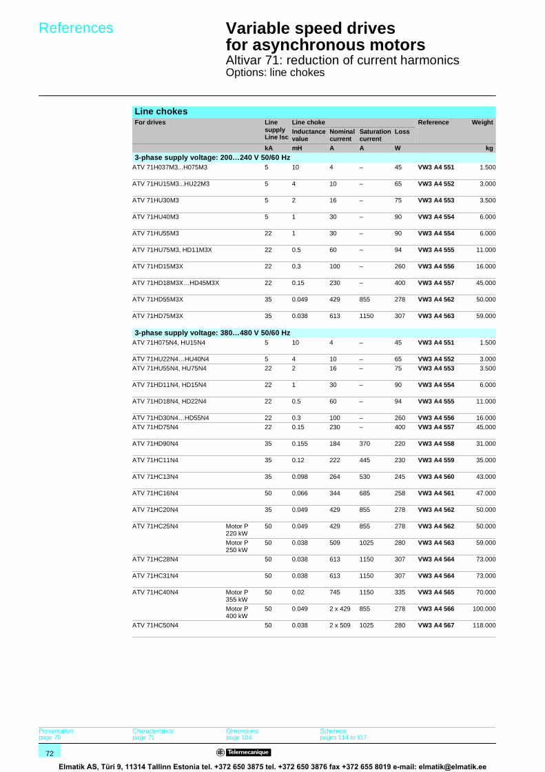
72
References 1 Variable speed drivesfor asynchronous motors 1
Altivar 71: reduction of current harmonicsOptions: line chokes
Line chokesFor drives Line
supplyLine Isc
Line choke Reference WeightInductancevalue
Nominal current
Saturation current
Loss
kA mH A A W kg
3-phase supply voltage: 200…240 V 50/60 HzATV 71H037M3...H075M3 5 10 4 – 45 VW3 A4 551 1.500
ATV 71HU15M3...HU22M3 5 4 10 – 65 VW3 A4 552 3.000
ATV 71HU30M3 5 2 16 – 75 VW3 A4 553 3.500
ATV 71HU40M3 5 1 30 – 90 VW3 A4 554 6.000
ATV 71HU55M3 22 1 30 – 90 VW3 A4 554 6.000
ATV 71HU75M3, HD11M3X 22 0.5 60 – 94 VW3 A4 555 11.000
ATV 71HD15M3X 22 0.3 100 – 260 VW3 A4 556 16.000
ATV 71HD18M3X…HD45M3X 22 0.15 230 – 400 VW3 A4 557 45.000
ATV 71HD55M3X 35 0.049 429 855 278 VW3 A4 562 50.000
ATV 71HD75M3X 35 0.038 613 1150 307 VW3 A4 563 59.000
3-phase supply voltage: 380…480 V 50/60 HzATV 71H075N4, HU15N4 5 10 4 – 45 VW3 A4 551 1.500
ATV 71HU22N4…HU40N4 5 4 10 – 65 VW3 A4 552 3.000
ATV 71HU55N4, HU75N4 22 2 16 – 75 VW3 A4 553 3.500
ATV 71HD11N4, HD15N4 22 1 30 – 90 VW3 A4 554 6.000
ATV 71HD18N4, HD22N4 22 0.5 60 – 94 VW3 A4 555 11.000
ATV 71HD30N4…HD55N4 22 0.3 100 – 260 VW3 A4 556 16.000
ATV 71HD75N4 22 0.15 230 – 400 VW3 A4 557 45.000
ATV 71HD90N4 35 0.155 184 370 220 VW3 A4 558 31.000
ATV 71HC11N4 35 0.12 222 445 230 VW3 A4 559 35.000
ATV 71HC13N4 35 0.098 264 530 245 VW3 A4 560 43.000
ATV 71HC16N4 50 0.066 344 685 258 VW3 A4 561 47.000
ATV 71HC20N4 35 0.049 429 855 278 VW3 A4 562 50.000
ATV 71HC25N4 Motor P 220 kW
50 0.049 429 855 278 VW3 A4 562 50.000
Motor P 250 kW
50 0.038 509 1025 280 VW3 A4 563 59.000
ATV 71HC28N4 50 0.038 613 1150 307 VW3 A4 564 73.000
ATV 71HC31N4 50 0.038 613 1150 307 VW3 A4 564 73.000
ATV 71HC40N4 Motor P 355 kW
50 0.02 745 1150 335 VW3 A4 565 70.000
Motor P 400 kW
50 0.049 2 x 429 855 278 VW3 A4 566 100.000
ATV 71HC50N4 50 0.038 2 x 509 1025 280 VW3 A4 567 118.000
Presentation:page 70
Characteristics:page 71
Dimensions:page 104
Schemes:pages 114 to 117
Elmatik AS, Türi 9, 11314 Tallinn Estonia tel. +372 650 3875 tel. +372 650 3876 fax +372 655 8019 e-mail: [email protected]

73
Presentation,characteristics 1
Variable speed drivesfor asynchronous motors 1
Altivar 71: reduction of current harmonicsOptions: passive filters
Passive filtersThe passive filter is used to reduce current harmonics with total harmonic distortion factors of less than 16% or 10%. These ratios may be less than 10% or 5% if used with a DC choke, see page 66.
ApplicationsReduction of current harmonics in order to use drives in the first environment.
General characteristicsDegree of protection IP 20
Maximum relative humidity Class F humidity without condensation 5%…85%
Ambient air temperaturearound the device
Operation °C 5…+ 40 without derating Up to 55°C with current derating of 3% per additional °C
Storage °C - 25…+ 55
Maximum operating altitude m 1000 without derating1000…4000 with current derating of 5% per additional 1000 m
Electrical characteristicsRange 400 V 460 V
Nominal voltage ± 10% V a 380…415 a 440…480
Operating frequency 50 ± 5% 60 ± 5%
Overload capacity 1.5 x Irms (A)
Efficiency 98% (2% of thermal losses)
THDI (1) % ≤ 16
Cos ϕ At 75% of the line current: 0.85At 100% of the line current: 0.99At 150% of the line current: 1
Connection characteristicsMaximum connectioncapacity
VW3 A4 601…604 16 mm2
VW3 A4 605…609 50 mm2
VW3 A4 610, 611, 614 Connected on a bar, Ø 12.5
VW3 A4 612, 613, 615…617 Connected on a bar, Ø 16.5
VW3 A4 621, 622 16 mm2
VW3 A4 623…627 50 mm2
VW3 A4 628, 629 Connected on a bar, Ø 12.5
VW3 A4 630…637 Connected on a bar, Ø 16.5VW3 A4 641…644 16 mm2
VW3 A4 645…648 50 mm2
VW3 A4 649 Connected on a bar, Ø 12.5VW3 A4 650…655 Connected on a bar, Ø 16.5
VW3 A4 661…663 16 mm2
VW3 A4 664…666 50 mm2
VW3 A4 667, 668 Connected on a bar, Ø 12.5
VW3 A4 669…675 Connected on a bar, Ø 16.5
(1) The total current harmonic distortion (THDI) is indicated for a total voltage harmonic distortion (THDU) < 2% and a short-circuit ratio (RSCE) > 66%. If these conditions are not adhered to, the total current harmonics will be reduced without any guarantee of level.
L1
L2
L3
Altivar 71
Passive filter
References:page 74
Dimensions:page 105
Schemes:page 122
Elmatik AS, Türi 9, 11314 Tallinn Estonia tel. +372 650 3875 tel. +372 650 3876 fax +372 655 8019 e-mail: [email protected]
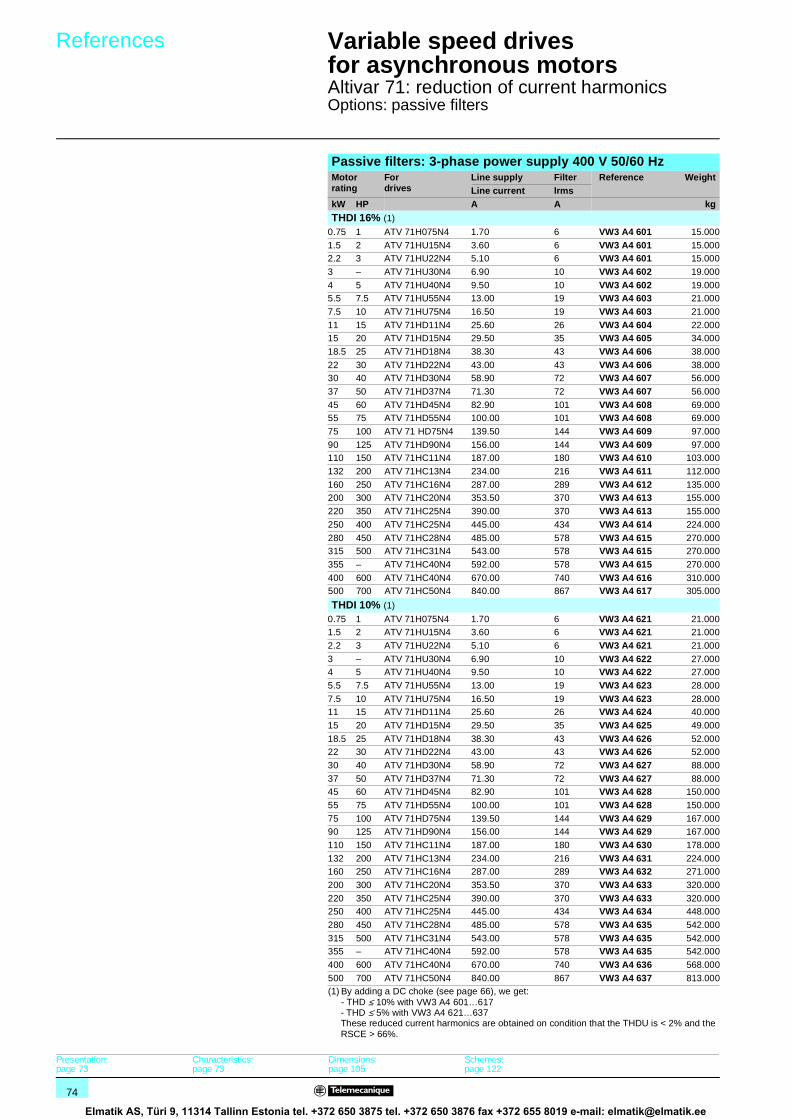
74
References 1 Variable speed drivesfor asynchronous motors 1
Altivar 71: reduction of current harmonicsOptions: passive filters
Passive filters: 3-phase power supply 400 V 50/60 HzMotor rating
Fordrives
Line supply Filter Reference WeightLine current lrms
kW HP A A kg
THDI 16% (1)
0.75 1 ATV 71H075N4 1.70 6 VW3 A4 601 15.000
1.5 2 ATV 71HU15N4 3.60 6 VW3 A4 601 15.0002.2 3 ATV 71HU22N4 5.10 6 VW3 A4 601 15.000
3 – ATV 71HU30N4 6.90 10 VW3 A4 602 19.000
4 5 ATV 71HU40N4 9.50 10 VW3 A4 602 19.0005.5 7.5 ATV 71HU55N4 13.00 19 VW3 A4 603 21.000
7.5 10 ATV 71HU75N4 16.50 19 VW3 A4 603 21.000
11 15 ATV 71HD11N4 25.60 26 VW3 A4 604 22.00015 20 ATV 71HD15N4 29.50 35 VW3 A4 605 34.000
18.5 25 ATV 71HD18N4 38.30 43 VW3 A4 606 38.000
22 30 ATV 71HD22N4 43.00 43 VW3 A4 606 38.00030 40 ATV 71HD30N4 58.90 72 VW3 A4 607 56.000
37 50 ATV 71HD37N4 71.30 72 VW3 A4 607 56.000
45 60 ATV 71HD45N4 82.90 101 VW3 A4 608 69.00055 75 ATV 71HD55N4 100.00 101 VW3 A4 608 69.000
75 100 ATV 71 HD75N4 139.50 144 VW3 A4 609 97.000
90 125 ATV 71HD90N4 156.00 144 VW3 A4 609 97.000110 150 ATV 71HC11N4 187.00 180 VW3 A4 610 103.000
132 200 ATV 71HC13N4 234.00 216 VW3 A4 611 112.000
160 250 ATV 71HC16N4 287.00 289 VW3 A4 612 135.000200 300 ATV 71HC20N4 353.50 370 VW3 A4 613 155.000
220 350 ATV 71HC25N4 390.00 370 VW3 A4 613 155.000
250 400 ATV 71HC25N4 445.00 434 VW3 A4 614 224.000
280 450 ATV 71HC28N4 485.00 578 VW3 A4 615 270.000315 500 ATV 71HC31N4 543.00 578 VW3 A4 615 270.000
355 – ATV 71HC40N4 592.00 578 VW3 A4 615 270.000
400 600 ATV 71HC40N4 670.00 740 VW3 A4 616 310.000500 700 ATV 71HC50N4 840.00 867 VW3 A4 617 305.000
THDI 10% (1)
0.75 1 ATV 71H075N4 1.70 6 VW3 A4 621 21.0001.5 2 ATV 71HU15N4 3.60 6 VW3 A4 621 21.000
2.2 3 ATV 71HU22N4 5.10 6 VW3 A4 621 21.000
3 – ATV 71HU30N4 6.90 10 VW3 A4 622 27.0004 5 ATV 71HU40N4 9.50 10 VW3 A4 622 27.000
5.5 7.5 ATV 71HU55N4 13.00 19 VW3 A4 623 28.000
7.5 10 ATV 71HU75N4 16.50 19 VW3 A4 623 28.00011 15 ATV 71HD11N4 25.60 26 VW3 A4 624 40.000
15 20 ATV 71HD15N4 29.50 35 VW3 A4 625 49.000
18.5 25 ATV 71HD18N4 38.30 43 VW3 A4 626 52.00022 30 ATV 71HD22N4 43.00 43 VW3 A4 626 52.000
30 40 ATV 71HD30N4 58.90 72 VW3 A4 627 88.000
37 50 ATV 71HD37N4 71.30 72 VW3 A4 627 88.00045 60 ATV 71HD45N4 82.90 101 VW3 A4 628 150.000
55 75 ATV 71HD55N4 100.00 101 VW3 A4 628 150.000
75 100 ATV 71HD75N4 139.50 144 VW3 A4 629 167.00090 125 ATV 71HD90N4 156.00 144 VW3 A4 629 167.000
110 150 ATV 71HC11N4 187.00 180 VW3 A4 630 178.000
132 200 ATV 71HC13N4 234.00 216 VW3 A4 631 224.000160 250 ATV 71HC16N4 287.00 289 VW3 A4 632 271.000
200 300 ATV 71HC20N4 353.50 370 VW3 A4 633 320.000
220 350 ATV 71HC25N4 390.00 370 VW3 A4 633 320.000250 400 ATV 71HC25N4 445.00 434 VW3 A4 634 448.000
280 450 ATV 71HC28N4 485.00 578 VW3 A4 635 542.000
315 500 ATV 71HC31N4 543.00 578 VW3 A4 635 542.000355 – ATV 71HC40N4 592.00 578 VW3 A4 635 542.000
400 600 ATV 71HC40N4 670.00 740 VW3 A4 636 568.000
500 700 ATV 71HC50N4 840.00 867 VW3 A4 637 813.000(1) By adding a DC choke (see page 66), we get:
- THD ≤ 10% with VW3 A4 601…617- THD ≤ 5% with VW3 A4 621…637These reduced current harmonics are obtained on condition that the THDU is < 2% and the RSCE > 66%.
Presentation:page 73
Characteristics:page 73
Dimensions:page 105
Schemes:page 122
Elmatik AS, Türi 9, 11314 Tallinn Estonia tel. +372 650 3875 tel. +372 650 3876 fax +372 655 8019 e-mail: [email protected]

75
References (continued) 1 Variable speed drivesfor asynchronous motors 1
Altivar 71: reduction of current harmonicsOptions: passive filters
Passive filters: 3-phase power supply 460 V 50/60 HzMotor rating
Fordrives
Line supply Filter Reference WeightLine current lrms
kW HP A A kg
THDI 16% (1)
0.75 1 ATV 71H075N4 1.60 6 VW3 A4 641 15.000
1.5 2 ATV 71HU15N4 3.00 6 VW3 A4 641 15.0002.2 3 ATV 71HU22N4 4.20 6 VW3 A4 641 15.000
3 – ATV 71HU30N4 6.20 6 VW3 A4 641 15.000
4 5 ATV 71HU40N4 6.90 10 VW3 A4 642 19.0005.5 7.5 ATV 71HU55N4 10.10 10 VW3 A4 642 19.000
7.5 10 ATV 71HU75N4 13.10 19 VW3 A4 643 23.000
11 15 ATV 71HD11N4 19.00 19 VW3 A4 643 23.00015 20 ATV 71HD15N4 24.10 26 VW3 A4 644 34.000
18.5 25 ATV 71HD18N4 31.70 35 VW3 A4 645 42.000
22 30 ATV 71HD22N4 36.00 35 VW3 A4 645 42.00030 40 ATV 71HD30N4 46.40 43 VW3 A4 646 45.000
37 50 ATV 71HD37N4 58.70 72 VW3 A4 647 61.000
45 60 ATV 71HD45N4 67.90 72 VW3 A4 647 61.00055 75 ATV 71HD55N4 82.60 101 VW3 A4 648 75.000
75 100 ATV 71 HD75N4 108.00 101 VW3 A4 648 75.000
90 125 ATV 71HD90N4 158.00 180 VW3 A4 649 107.000110 150 ATV 71HC11N4 187.00 180 VW3 A4 649 107.000
132 200 ATV 71HC13N4 234.00 289 VW3 A4 650 145.000
160 250 ATV 71HC16N4 287.00 289 VW3 A4 650 145.000200 300 ATV 71HC20N4 353.00 370 VW3 A4 651 185.000
220 350 ATV 71HC25N4 390.00 370 VW3 A4 651 185.000
250 400 ATV 71HC25N4 444.00 432 VW3 A4 652 238.000
280 450 ATV 71HC28N4 485.00 578 VW3 A4 653 290.000315 500 ATV 71HC31N4 543.00 578 VW3 A4 653 290.000
355 – ATV 71HC40N4 591.80 578 VW3 A4 653 290.000
400 600 ATV 71HC40N4 669.40 740 VW3 A4 654 370.000500 700 ATV 71HC50N4 840.00 867 VW3 A4 655 435.000
THDI 10% (1)
0.75 1 ATV 71H075N4 1.70 6 VW3 A4 661 21.0001.5 2 ATV 71HU15N4 3.60 6 VW3 A4 661 21.000
2.2 3 ATV 71HU22N4 5.10 6 VW3 A4 661 21.000
3 – ATV 71HU30N4 6.90 6 VW3 A4 661 21.0004 5 ATV 71HU40N4 9.50 10 VW3 A4 662 27.000
5.5 7.5 ATV 71HU55N4 13.00 10 VW3 A4 662 27.000
7.5 10 ATV 71HU75N4 16.50 19 VW3 A4 663 28.00011 15 ATV 71HD11N4 25.60 19 VW3 A4 663 28.000
15 20 ATV 71HD15N4 29.50 26 VW3 A4 664 41.000
18.5 25 ATV 71HD18N4 38.30 35 VW3 A4 665 49.00022 30 ATV 71HD22N4 43.00 35 VW3 A4 665 49.000
30 40 ATV 71HD30N4 58.90 43 VW3 A4 666 56.000
37 50 ATV 71HD37N4 71.30 72 VW3 A4 667 80.00045 60 ATV 71HD45N4 82.90 72 VW3 A4 668 98.000
55 75 ATV 71HD55N4 100.00 101 VW3 A4 668 98.000
75 100 ATV 71HD75N4 139.50 101 VW3 A4 668 98.00090 125 ATV 71HD90N4 156.00 180 VW3 A4 669 151.000
110 150 ATV 71HC11N4 187.00 180 VW3 A4 669 151.000
132 200 ATV 71HC13N4 234.00 289 VW3 A4 670 215.000160 250 ATV 71HC16N4 287.00 289 VW3 A4 670 215.000
200 300 ATV 71HC20N4 353.50 370 VW3 A4 671 250.000
220 350 ATV 71HC25N4 390.00 370 VW3 A4 671 250.000250 400 ATV 71HC25N4 445.00 432 VW3 A4 672 342.000
280 450 ATV 71HC28N4 485.00 578 VW3 A4 673 430.000
315 500 ATV 71HC31N4 543.00 578 VW3 A4 673 430.000355 – ATV 71HC40N4 592.00 578 VW3 A4 673 430.000
400 600 ATV 71HC40N4 670.00 740 VW3 A4 674 500.000
500 700 ATV 71HC50N4 840.00 867 VW3 A4 675 645.000(1) By adding a DC choke (see page 66), we get:
- THD ≤ 10% with VW3 A4 641…655- THD ≤ 5% with VW3 A4 661…675These reduced current harmonics are obtained on condition that the THDU is < 2% and the RSCE > 66%.
Presentation:page 73
Characteristics:page 73
Dimensions:page 105
Schemes:page 122
Elmatik AS, Türi 9, 11314 Tallinn Estonia tel. +372 650 3875 tel. +372 650 3876 fax +372 655 8019 e-mail: [email protected]

76
Presentation 1 Variable speed drivesfor asynchronous motors 1
Altivar 71Options: additional EMC input filters
Altivar 71 drives, except for the ATV 71HpppM3X, have built-in radio interference input filters to meet the EMC standard for variable speed electrical power drive “products” IEC/EN 61800-3, edition 2, category C2 or C3 in environment 1 or 2 and to comply with the European directive on EMC (electromagnetic compatibility).
For drivesEN 55011
Maximum length of shielded cable according toclass A (1)
Group 1 (2) Group 2 (2)
LF (3) HF (3) LF (3) HF (3)m m m m
ATV 71H037M3…HU22M3 10 5 – –
ATV 71HU30M3…HU75M3 – – 10 5ATV 71H075N4…HU40N4 10 5 – –
ATV 71HU55N4…HD15N4 – – 10 5
ATV 71HD18N4…HC50N4 – – 50 25
For drives Switching frequencyLF HFkHz kHz
ATV 71HpppM3ATV 71H075N4…HD30N4
3…4 4.1…16
ATV 71HD37N4…HD75N4 2…2.5 2.6…12ATV 71HD90N4…HC50N4 2…4 4.1…8
M1 3
L1
L2
L3
ATV 71pppppM3ATV 71pppppN4with built-in filter
Additional EMC input filtersApplications
M1 3 Altivar 71
L1
L2
L3
Additional EMC filter
Additional EMC input filters can be used to meet more stringent requirements and are designed to reduce conducted emissions on the line supply below the limits of standard EN 55011 group 1, class A or B (2).These additional filters are mounted under the drives. They can be mounted on the side of the product for ATV 71HpppM3, ATV 71HD11M3X…HD45M3X and ATV 71H075N4…HD75N4 drives. They act as a support for the drives and are fixed to them via tapped holes.
Use according to the type of networkUse of these additional filters is only possible on TN (connected to neutral) and TT (neutral to earth) type networks.
Standard IEC/EN 61800-3, appendix D2.1, states that on IT networks (impedance or isolated neutral), filters can cause permanent insulation monitors to operate in a random manner.In addition, the effectiveness of additional filters on this type of network depends on the type of impedance between neutral and ground, and therefore cannot be predicted.In the case of a machine which needs to be installed on an IT network, one solution consists of inserting an isolation transformer and placing the machine locally on a TN or TT network.(1) Maximum lengths for shielded cables connecting motors to drives, for a factory-set switching
frequency of 2.5 or 4 kHz depending on the rating (2). If motors are connected in parallel, it is the sum of all cable lengths that should be taken into account.
(2) See page 8.(3) LF: low switching frequency. HF: high switching frequency. These frequencies depend on the
drive rating.
Characteristics:Page 77
References:Pages 78 and 79
Dimensions:Pages 106 and 107
Schemes:Page 122
Elmatik AS, Türi 9, 11314 Tallinn Estonia tel. +372 650 3875 tel. +372 650 3876 fax +372 655 8019 e-mail: [email protected]

77
Characteristics 1 Variable speed drivesfor asynchronous motors 1
Altivar 71Options: additional EMC input filters
General characteristicsEMC filter VW3 A4 401…409 VW3 A4 410…414
Conformity to standards EN 133200
Degree of protection IP 20 and IP 41 on upper part IP 00IP 30 with VW3 A9 601, 602 kits
Maximum relative humidity 93% without condensation or dripping water conforming to IEC 68-2-3
Ambient temperaturearound the unit
Operation °C - 10…+ 50 - 25…+ 45
Storage °C - 40…+ 65 - 25…+ 85Maximum operating altitude m 1000 without derating
1000…3000 by derating the current by 1% per additional 100 m Limited to 2000 m for the “Corner Grounded” distribution network
Vibration resistance 1.5 mm peak to peak from 3…13 Hz, 1 gn peak from 13…150 Hz, in accordance with IEC 60068-2-6
Shock resistance 15 gn for 11 ms, in accordance with IEC 60068-2-27Maximum nominal voltage 50/60 Hz 3-phase V 240 + 10%
480 + 10%
Connection characteristicsMaximum connection capacity and tightening torque
VW3 A4 401 4 mm2 (AWG 10).0.6 Nm
VW3 A4 402 6 mm2 (AWG 8).1.5 Nm
VW3 A4 403 10 mm2 (AWG 6).1.5 Nm
VW3 A4 404 16 mm2 (AWG 4).2 Nm
VW3 A4 405…407 50 mm2 (AWG 0).6 Nm
VW3 A4 408 150 mm2 (300 kcmil).25 Nm
VW3 A4 409 25 mm2 (AWG 2).4 Nm
VW3 A4 410…412 Bar connection, M10–
VW3 A4 413 Bar connection, 2 x M12–
Presentation:Page 76
References:Pages 78 and 79
Dimensions:Pages 106 and 107
Schemes:Page 122
Elmatik AS, Türi 9, 11314 Tallinn Estonia tel. +372 650 3875 tel. +372 650 3876 fax +372 655 8019 e-mail: [email protected]

78
References 1 Variable speed drivesfor asynchronous motors 1
Altivar 71Options: additional EMC input filters
Additional EMC input filtersFor drives Maximum length of shielded cable
(1)In(2)
Il(3)
Loss (4)
Reference Weight
EN 55011 (5) class A Gr1
EN 55011 (5) class B Gr1
LF (6) HF (6) LF (6) HF (6)
m m m m A mA W kg
3-phase supply voltage: 200…240 V 50/60 HzATV 71H037M3…HU15M3 100 50 50 20 12 4 10 VW3 A4 401 2.200
ATV 71HU22M3…HU40M3 100 50 50 20 26 4.4 18 VW3 A4 402 4.000
ATV 71HU55M3 100 50 50 20 35 3 24 VW3 A4 403 5.800
ATV 71HU75M3 100 50 50 20 46 10 19 VW3 A4 404 7.000
ATV 71HD11M3X, HD15M3X 100 50 50 25 72 33 34 VW3 A4 405 12.000
ATV 71HD18M3X, HD22M3X 100 50 50 25 90 33 34 VW3 A4 406 15.000
ATV 71HD30M3X...HD45M3X 100 50 50 25 180 80 58 VW3 A4 408 40.000
ATV 71HD55M3X, HD75M3X 100 50 50 25 273 285 60 VW3 A4 410 22.000
3-phase supply voltage: 380…480 V 50/60 HzATV 71H075N4…HU22N4 100 50 50 20 12 7 5 VW3 A4 401 2.200
ATV 71HU30N4, HU40N4 100 50 50 20 26 8 6 VW3 A4 402 4.000
ATV 71HU55N4, HU75N4 100 50 50 20 35 7 14 VW3 A4 403 5.800
ATV 71HD11N4 100 50 50 20 46 14 13 VW3 A4 404 7.000
ATV 71HD15N4 (7), HD18N4 300 200 100 100 72 60 14 VW3 A4 405 12.000
ATV 71HD22N4 300 200 100 100 90 60 11 VW3 A4 406 15.000
ATV 71HD30N4, HD37N4 300 200 100 100 92 60 30 VW3 A4 407 17.000
ATV 71HD45N4…HD75N4 300 200 100 100 180 140 58 VW3 A4 408 40.000
ATV 71HD90N4…HC13N4 300 150 50 25 273 500 60 VW3 A4 410 22.000
ATV 71HC16N4…HC28N4 300 150 50 25 546 500 125 VW3 A4 411 25.000
ATV 71HC31...HC40N4 300 150 50 25 728 500 210 VW3 A4 412 25.000
ATV 71HC50N4 300 150 50 25 1456 200 380 VW3 A4 413 34.000
(1) The filter selection tables give the maximum lengths for shielded cables connecting motors to drives for a switching frequency of 1 to 16 kHz (5). These limits are given as examples only as they vary depending on the stray capacitance of the motors and the cables used. If motors are connected in parallel, it is the sum of the cable lengths that should be taken into account.
(2) Filter nominal current.(3) Maximum earth leakage current at 230 V and at 400 V 50 Hz on a TT network.(4) Via thermal dissipation.(5) See page 8.(6) LF: low switching frequency. HF: high switching frequency. These frequencies depend on the drive rating:For drives Switching frequency
LF HFkHz kHz
ATV 71HpppM3ATV 71H075N4…HD11N4
3…4 4.1…16
ATV 71HD11M3X, HD15M3XATV 71HD15N4…HD30N4
3.5...4 4.1…12
ATV 71HD18M3X...HD45M3XATV 71HD37N4...HD75N4
2…2.5 2.6…12
ATV 71HD55M3X, HD75M3X 2…4 4.1…8
ATV 71HD90N4, HC50N4 2…4 4.1…8
(7) It is possible to use a special filter VW3 A4 409 with a leakage current Il (3) of 14 mA which enables a maximum motor cable length of 100 m.
Presentation:Page 76
Characteristics:Page 77
Dimensions:Pages 106 and 107
Schemes:Page 122
Elmatik AS, Türi 9, 11314 Tallinn Estonia tel. +372 650 3875 tel. +372 650 3876 fax +372 655 8019 e-mail: [email protected]

79
References (continued) 1 Variable speed drivesfor asynchronous motors 1
Options: additional EMC input filters
IP 30 protection kitsDescription For filters Reference Weight
kgMechanical deviceconsisting of anIP 30 cover andcable clips
VW3 A4 410, 411 VW3 A9 601 –
VW3 A4 412, 413 VW3 A9 602 –
Presentation:Page 76
Characteristics:Page 77
Dimensions:Page 107
Schemes:Page 122
Elmatik AS, Türi 9, 11314 Tallinn Estonia tel. +372 650 3875 tel. +372 650 3876 fax +372 655 8019 e-mail: [email protected]

80
Presentation 1 Variable speed drivesfor asynchronous motors 1
Altivar 71: output filters
The Altivar 71 drive includes as standard a software function used to limit overvoltages at the motor terminals.Depending on the cable lengths or the type of application, it may be necessary to use output filters:b Motor chokes used to limit the dv/dtb Sinus filters that are particularly effective for long cable runs
Cable length (2) 10…50 m 50…100 m 100…150 m 150…300 m 300…600 m 600…1000 m
Shielded cableATV 71HpppM3ATV 71H075N4…HD15N4
Software function (1)
Motor choke –
ATV 71HpppM3XATV 71HD18N4…HC50N4
Software function (1) Motor choke –
Unshielded cableATV 71H037M3...HU15M3ATV 71H075N4...HU22N4
Software function (1) Motor choke orsinus filter
–
ATV 71HU22M3...HU30M3ATV 71HU55N4…HU75N4
Software function (1) Motor choke Sinus filter –
ATV 71HU40M3…HU75M3ATV 71HU75N4…HD15N4
Software function (1) Motor choke Sinus filter
ATV 71HpppM3XATV 71HD18N4…HC50N4
Software function (1) Motor choke Sinus filter
(1) The software function limits the overvoltage at the motor terminals to twice the DC bus voltage.For any application with braking cycles, the DC bus voltage rises to more than the supply voltage multiplied by 2. You must check the electrical characteristics of the motor before using this function.
(2) For an application with several motors connected in parallel, the cable length must include all cabling.Type of recommended cable: b Shielded cables: “GORSE” cable, type GUOSTV-LS/LH; “PROTOFLEX” cable, type EMV2YSL CYb Unshielded cables: “GORSE” cable, type H07 RN-F4GXX; “BELDEN” cable, type 2950X
Schemes:page 122
Elmatik AS, Türi 9, 11314 Tallinn Estonia tel. +372 650 3875 tel. +372 650 3876 fax +372 655 8019 e-mail: [email protected]

81
Presentation,characteristics 1
Variable speed drivesfor asynchronous motors 1
Altivar 71: output filtersOptions: motor chokes
Above a certain motor cable length, it is advisable to insert a motor choke between the drive and the motor. This maximum length depends on the drive rating and the type of motor cable:
The choke is used to:b Limit the dv/dt to 500 V/µsb Limit overvoltages on the motor terminals to:v 1000 V to 400 V a (rms value)v 1150 V to 460 V a (rms value)b Filter interference caused by opening a contactor placed between the filter and the motorb Reduce the motor earth leakage current
(1) These values are given for a switching frequency of 2.5 or 4 kHz depending on the rating.(2) Choke performance is ensured by not exceeding the cable lengths between the motor and the drive given in the table above. For an application with several
motors connected in parallel, the cable length must include all cabling. If a cable longer than that recommended is used, the motor chokes may overheat.(3) The contact should be connected in the sequence (use for signalling or in line contactor control).
Motor chokes
For drives Maximum length of motor cable (1)
Shielded cable Unshielded cablem m
ATV 71HpppM3ATV 71HD11M3X, HD15M3XATV 71H075N4…HD18N4
u 50 u 100
ATV 71HD18M3X…HD75M3XATV 71HD22N4…HC50N4
u 100 u 200
M1 3
Altivar 71
Motor choke
General characteristics (2)
Type of choke VW3 A5 101…103 VW3 A5 104…108Drive switching frequency ATV 71HpppM3
ATV 71HD11M3X, HD15M3XATV 71H075N4…HD30N4
kHz 4
ATV 71HD18M3X…HD75M3XATV 71HD37N4…HC50N4
kHz 2.5
Maximum drive output frequency Hz 100
Degree of protection IP 00 IP 00IP 20 with kits VW3 A9 612 and VW3 A9 613
Thermal protection By temperature controlled switch –Temperature controlled switch (3)
Tripping temperature °C 125 –
Maximum voltage V a 250 –
Maximum current A 0.5 –Ambient temperaturearound the unit
Operation °C - 10…+ 50
Storage °C - 25…+ 70
Connection characteristicsMaximum connection capacity and tightening torque
VW3 A5 101, 102 10 mm2 (AWG 6)1.5 Nm
VW3 A5 103 Connected on a bar, Ø 11 mm–
VW3 A5 104 Connected on a tag connector, M10–
VW3 A5 105, 106 Connected on a tag connector, M12–
VW3 A5 107, 108 Connected on a tag connector, 2 x M12–
References:page 82
Dimensions:pages 108 and 109
Schemes:page 122
Elmatik AS, Türi 9, 11314 Tallinn Estonia tel. +372 650 3875 tel. +372 650 3876 fax +372 655 8019 e-mail: [email protected]

82
References 1 Variable speed drivesfor asynchronous motors 1
Altivar 71: output filtersOptions: motor chokes
Motor chokesFor drives Maximum motor
cable lengthLoss Nominal
currentReference Weight
Shielded Unshieldedm m W A kg
3-phase supply voltage: 200…240 V 50/60 HzATV 71H037M3…HU22M3 150 300 150 12 VW3 A5 101 5.500
ATV 71HU30M3…HU75M3 200 260 250 48 VW3 A5 102 8.000
300 300 350 90 VW3 A5 103 10.000
ATV 71HD11M3X…HD22M3X 150 300 350 90 VW3 A5 103 10.000
ATV 71HD30M3X…HD45M3X 150 300 430 3 x 215 VW3 A5 104 (1) 17.300
ATV 71HD55M3X, HD75M3X 150 300 475 3 x 314 VW3 A5 105 (1) 29.600
3-phase supply voltage: 380…480 V 50/60 HzATV 71H075N4…HU40N4 75 90 150 12 VW3 A5 101 5.500
85 95 250 48 VW3 A5 102 8.000
160 200 350 90 VW3 A5 103 10.000
ATV 71HU55N4…HD18N4 85 95 250 48 VW3 A5 102 8.000
160 200 350 90 VW3 A5 103 10.000
200 300 430 3 x 215 VW3 A5 104 (1) 17.300
ATV 71HD22N4…HD30N4 140 170 350 90 VW3 A5 103 10.000
150 300 430 3 x 215 VW3 A5 104 (1) 17.300
ATV 71HD37N4 97 166 350 90 VW3 A5 103 10.000
200 300 430 3 x 215 VW3 A5 104 (1) 17.300
ATV 71HD45N4…HD75N4 150 300 430 3 x 215 VW3 A5 104 (1) 17.300
ATV 71HD90N4 200 300 430 3 x 215 VW3 A5 104 (1) 17.300
ATV 71HC11N4, HC13N4 150 250 475 3 x 314 VW3 A5 105 (1) 29.600
ATV 71HC16N4…HC20N4 250 300 530 3 x 481 VW3 A5 106 (1) 44.400
ATV 71HC25N4 Motor P 220 kW 250 300 530 3 x 481 VW3 A5 106 (1) 44.400
Motor P 250 kW 200 250 598 3 x 759 VW3 A5 107 (1) 64.500
ATV 71HC28N4, HC31N4 200 250 598 3 x 759 VW3 A5 107 (1) 64.500
ATV 71HC40N4 Motor P 355 kW 200 250 598 3 x 759 VW3 A5 107 (1) 64.500
Motor P 400 kW 250 300 682 3 x 1188 VW3 A5 108 (1) 99.200
ATV 71HC50N4 250 300 682 3 x 1188 VW3 A5 108 (1) 99.200
(1) 3 single-phase chokes are included with the drive.
VW3 A5 101
Presentation:page 80
Characteristics:page 81
Dimensions:pages 108 and 109
Schemes:page 122
Elmatik AS, Türi 9, 11314 Tallinn Estonia tel. +372 650 3875 tel. +372 650 3876 fax +372 655 8019 e-mail: [email protected]

83
References (continued) 1 Variable speed drivesfor asynchronous motors 1
Altivar 71: output filtersOptions: motor chokes
IP 20 protection kitsDescription For filters Reference Weight
kgMechanical kit including an IP 20 cover and cable clamps
VW3 A5 104, 105 VW3 A9 612 –
VW3 A5 106…108 VW3 A9 613 –
Presentation:page 80
Characteristics:page 81
References:page 82
Dimensions:page 109
Schemes:page 122
Elmatik AS, Türi 9, 11314 Tallinn Estonia tel. +372 650 3875 tel. +372 650 3876 fax +372 655 8019 e-mail: [email protected]

84
Presentation,characteristics 1
Variable speed drivesfor asynchronous motors 1
Altivar 71: output filtersOptions: sinus filters
Sinus filtersSinus filters allow Altivar 71 drives to operate with longer motor cables (up to 1000 m).For ATV 71pppM3, ATV 71H037M3X...HU45M3X, ATV 71H075N4... HD75N4 drives, it also enables the use of unshielded cables while still complying with the standards on radiated EMC emissions (EN55011 class A Gr1).
ApplicationsApplications requiring:b Long cable runsb Mechanical restrictions preventing the use of shielded cablesb An intermediate transformer between the drive and the motorb Motors connected in parallel
General characteristicsType of choke VW3 A5 201…206 VW3 A5 207…211
Degree of protection IP 20 IP 00Atmospheric pollution 3C2, 3B1, 3S1 conforming to IEC 721.3.3
Degree of pollution 2 conforming to standard EN 50178
Vibration resistance 1.5 mm from 3...13 Hz, 1 gn from 13...200 Hz, conforming to IEC 60068-2Shock resistance 15 gn for 11 ms conforming to IEC 60068-2-27
Maximum relative humidity 95%
Ambient air temperaturearound the device
Operation °C - 10...+ 40 without deratingFrom 40...50°C with current derating of 1.5% per additional °C
Storage °C - 40…+ 65
Maximum operating altitude m 1000 without deratingFrom 1000…3000 with current derating of 1% per additional 100 m
Switching frequency kHz 4...8Output frequency Hz 0...100
Voltage drop < 10%
Maximum voltage V a 500Maximum current 1.5 x nominal current for 60 s
Maximum length ofmotor cable
Unshielded cable m 600 or 1000 depending on the drive rating, see page 80
Connection characteristicsMaximum connection capacity and tightening torque
VW3 A5 201 4 mm2 (AWG 10)0.6 Nm
VW3 A5 202 6 mm2 (AWG 8)1.5 Nm
VW3 A5 203 10 mm2 (AWG 6)1.5 Nm
VW3 A5 204 25 mm2 (AWG 2)4 Nm
VW3 A5 205 50 mm2 (AWG 0)6 Nm
VW3 A5 206, 207 95 mm2 (AWG 4/0)20 Nm
VW3 A5 208, 209 Connected on a bar, Ø 11 mm–
VW3 A5 210 Connected on a bar, Ø 14 mm–
VW3 A5 211 Connected on a bar, 4 x Ø 11 mm–
M1 3
Altivar 71
Sinus filter
References:page 85
Dimensions:pages 110 and 111
Schemes:page 122
Elmatik AS, Türi 9, 11314 Tallinn Estonia tel. +372 650 3875 tel. +372 650 3876 fax +372 655 8019 e-mail: [email protected]

85
References 1 Variable speed drivesfor asynchronous motors 1
Altivar 71: output filtersOptions: sinus filters
(1) For ATV 71H037M3…HU15M3 and ATV 71H075N4…HU22N4 drives, it is advisable to use a lower category of motor with a sinus filter.
Sinus filtersFor drives Nominal
currentLossat 100 Hz
Reference Weight
A W kg
3-phase supply voltage: 200…240 V 50/60 HzATV 71H037M3...HU15M3 (1) 11 50 VW3 A5 201 8.000
ATV 71HU22M3, HU30M3 16 70 VW3 A5 202 11.000
ATV 71HU40M3... HU75M3 33 120 VW3 A5 203 22.000
ATV 71HD11M3X, HD15M3X 66 180 VW3 A5 204 45.000
ATV 71HD18M3X, HD22M3X 95 250 VW3 A5 205 60.000
ATV 71HD30M3X... HD45M3X 180 400 VW3 A5 206 120.000
ATV 71HD55M3X, HD75M3X 300 1360 VW3 A5 208 165.000
3-phase supply voltage: 380…480 V 50/60 HzATV 71H075N4...HU40N4 (1) 11 50 VW3 A5 201 8.000
ATV 71HU55N4 16 70 VW3 A5 202 11.000
ATV 71HU75N4...HD15N4 33 120 VW3 A5 203 22.000
ATV 71HD18N4... HD30N4 66 180 VW3 A5 204 45.000
ATV 71HD37N4, HD45N4 95 250 VW3 A5 205 60.000
ATV 71HD55N4, HD75N4 180 400 VW3 A5 206 120.000
ATV 71 HD90N4, HC11N4 200 945 VW3 A5 207 130.000
ATV 71 HC13N4, HC16N4 300 1360 VW3 A5 208 165.000
ATV 71 HC20N4 400 1900 VW3 A5 209 190.000
ATV 71 HC25N4 Motor P 220 kW 400 1900 VW3 A5 209 190.000
Motor P 250 kW 600 2370 VW3 A5 210 260.000
ATV 71 HC28N4, HC31N4 600 2370 VW3 A5 210 260.000
ATV 71 HC40N4 Motor P 355 kW 600 2370 VW3 A5 210 260.000
Motor P 400 kW 1200 5150 VW3 A5 211 600.000
ATV 71 HC50N4 1200 5150 VW3 A5 211 600.000
Presentation:page 84
Characteristics:page 84
Dimensions:pages 110 and 111
Schemes:page 122
Elmatik AS, Türi 9, 11314 Tallinn Estonia tel. +372 650 3875 tel. +372 650 3876 fax +372 655 8019 e-mail: [email protected]

86
Combinations 1 Variable speed drivesfor asynchronous motors 1
Altivar 71
Table showing possible combinations of Altivar 71 drive options Motor Drive Options
kW HP
DC choke
Line choke Additional EMC input filter
Motor choke IP 20 motor choke kit
Single phase supply voltage: 200…240 V 50/60 Hz0.37 0.5 ATV 71H075M3 VW3 A4 503 VW3 A4 551 VW3 A4 401 VW3 A5 101 –
0.75 1 ATV 71HU15M3 VW3 A4 505 VW3 A4 552 VW3 A4 401 VW3 A5 101 –
1.5 2 ATV 71HU22M3 VW3 A4 506 VW3 A4 552 VW3 A4 402 VW3 A5 101 –
2.2 3 ATV 71HU30M3 VW3 A4 507 VW3 A4 553 VW3 A4 402 VW3 A5 102, 103 –
3 – ATV 71HU40M3 VW3 A4 508 VW3 A4 554 VW3 A4 402 VW3 A5 102, 103 –
4 5 ATV 71HU55M3 VW3 A4 508 VW3 A4 554 VW3 A4 403 VW3 A5 102, 103 –
5.5 7.5 ATV 71HU75M3 VW3 A4 509 VW3 A4 555 VW3 A4 404 VW3 A5 102, 103 –
3-phase supply voltage: 200…240 V 50/60 Hz0.37 0.5 ATV 71H037M3 VW3 A4 501 VW3 A4 551 VW3 A4 401 VW3 A5 101 –
0.75 1 ATV 71H075M3 VW3 A4 503 VW3 A4 551 VW3 A4 401 VW3 A5 101 –
1.5 2 ATV 71HU15M3 VW3 A4 505 VW3 A4 552 VW3 A4 401 VW3 A5 101 –
2.2 3 ATV 71HU22M3 VW3 A4 506 VW3 A4 552 VW3 A4 402 VW3 A5 101 –
3 – ATV 71HU30M3 VW3 A4 507 VW3 A4 553 VW3 A4 402 VW3 A5 102, 103 –
4 5 ATV 71HU40M3 VW3 A4 508 VW3 A4 554 VW3 A4 402 VW3 A5 102, 103 –
5.5 7.5 ATV 71HU55M3 VW3 A4 508 VW3 A4 554 VW3 A4 403 VW3 A5 102, 103 –
7.5 10 ATV 71HU75M3 VW3 A4 509 VW3 A4 555 VW3 A4 404 VW3 A5 102, 103 –
11 15 ATV 71HD11M3X VW3 A4 510 VW3 A4 555 VW3 A4 405 VW3 A5 103 –
15 20 ATV 71HD15M3X VW3 A4 510 VW3 A4 556 VW3 A4 405 VW3 A5 103 –
18.5 25 ATV 71HD18M3X VW3 A4 511 VW3 A4 557 VW3 A4 406 VW3 A5 103 –
22 30 ATV 71HD22M3X VW3 A4 511 VW3 A4 557 VW3 A4 406 VW3 A5 103 –
30 40 ATV 71HD30M3X VW3 A4 512 VW3 A4 557 VW3 A4 408 VW3 A5 104 VW3 A9 612
37 50 ATV 71HD37M3X VW3 A4 512 VW3 A4 557 VW3 A4 408 VW3 A5 104 VW3 A9 612
45 60 ATV 71HD45M3X VW3 A4 512 VW3 A4 557 VW3 A4 408 VW3 A5 104 VW3 A9 612
55 75 ATV 71HD55M3X – VW3 A4 562 VW3 A4 401 VW3 A5 105 VW3 A9 612
75 100 ATV 71HD75M3X – VW3 A4 563 VW3 A4 401 VW3 A5 105 VW3 A9 612
Pages 18 69 72 78 82 83
Table showing possible combinations of options common to all Altivar 71 drivesFor drives Logic input
adaptor a 115 V
I/O cards (1) Program-mable "Controller Inside" card
Remote graphic display terminal
Encoder interface cards PowerSuite software workshop for PC and Pocket PC
Logic Extended RS 422 compatible differential outputs
Open collector outputs
Push-pull outputs
ATV 71Hppppp
VW3 A3 101 VW3 A3 201 VW3 A3 202 VW3 A3 501 VW3 A1 101 VW3 A3 401, 402
VW3 A3 403, 404
VW3 A3 405 …407
VW3 A8 104, 105
Pages 20 31 31 39 26 29 29 29 179
(1) Maximum combination: 2 cards, in accordance with the compatibility table below:
Type of card CommunicationVW3 A3 3pp
Programmable “Controller inside” VW3 A3 501
Logic I/OVW3 A3 201
Extended I/OVW3 A3 202
CommunicationVW3 A3 3ppProgrammable “Controller inside” VW3 A3 501Logic I/OVW3 A3 201Extended I/OVW3 A3 202
Possible to combine
Not possible to combine
Elmatik AS, Türi 9, 11314 Tallinn Estonia tel. +372 650 3875 tel. +372 650 3876 fax +372 655 8019 e-mail: [email protected]

87
11
Sinus filter Braking resistor
Hoist resistor Flush-mounting kit (inside dust and damp proof enclosure)
NEMA Type 1 conformity kit (outside enclosure)
IP 21 or IP 31 conformity kit (outside enclosure)
Control card fan kit
VW3 A5 201 VW3 A7 701 VW3 A7 801 VW3 A9 501 VW3 A9 201 VW3 A9 101 –
VW3 A5 201 VW3 A7 702 VW3 A7 802 VW3 A9 501 VW3 A9 201 VW3 A9 101 –
VW3 A5 202 VW3 A7 702 VW3 A7 803 VW3 A9 502 VW3 A9 202 VW3 A9 102 –
VW3 A5 202 VW3 A7 703 VW3 A7 803 VW3 A9 502 VW3 A9 202 VW3 A9 102 –
VW3 A5 203 VW3 A7 703 VW3 A7 803 VW3 A9 502 VW3 A9 202 VW3 A9 102 –
VW3 A5 203 VW3 A7 704 VW3 A7 804 VW3 A9 503 VW3 A9 203 VW3 A9 103 –
VW3 A5 203 VW3 A7 704 VW3 A7 804 VW3 A9 504 VW3 A9 204 VW3 A9 104 –
VW3 A5 201 VW3 A7 701 VW3 A7 801 VW3 A9 501 VW3 A9 201 VW3 A9 101 –
VW3 A5 201 VW3 A7 701 VW3 A7 801 VW3 A9 501 VW3 A9 201 VW3 A9 101 –
VW3 A5 201 VW3 A7 702 VW3 A7 802 VW3 A9 501 VW3 A9 201 VW3 A9 101 –
VW3 A5 202 VW3 A7 702 VW3 A7 803 VW3 A9 502 VW3 A9 202 VW3 A9 102 –
VW3 A5 202 VW3 A7 703 VW3 A7 803 VW3 A9 502 VW3 A9 202 VW3 A9 102 –
VW3 A5 203 VW3 A7 703 VW3 A7 803 VW3 A9 502 VW3 A9 202 VW3 A9 102 –
VW3 A5 203 VW3 A7 704 VW3 A7 804 VW3 A9 503 VW3 A9 203 VW3 A9 103 –
VW3 A5 203 VW3 A7 704 VW3 A7 804 VW3 A9 504 VW3 A9 204 VW3 A9 104 –
VW3 A5 204 VW3 A7 705 VW3 A7 805 VW3 A9 505 VW3 A9 205 VW3 A9 105 –
VW3 A5 204 VW3 A7 706 VW3 A7 805 VW3 A9 505 VW3 A9 205 VW3 A9 105 –
VW3 A5 205 VW3 A7 707 VW3 A7 806 VW3 A9 506 VW3 A9 206 VW3 A9 106 VW3 A9 406
VW3 A5 205 VW3 A7 707 VW3 A7 807 VW3 A9 506 VW3 A9 206 VW3 A9 106 VW3 A9 406
VW3 A5 206 VW3 A7 708 VW3 A7 807 VW3 A9 508 VW3 A9 208 VW3 A9 108 –
VW3 A5 206 VW3 A7 709 VW3 A7 808 VW3 A9 508 VW3 A9 208 VW3 A9 108 –
VW3 A5 206 VW3 A7 709 VW3 A7 808 VW3 A9 508 VW3 A9 208 VW3 A9 108 –
VW3 A5 208 VW3 A7 713 VW3 A7 809 VW3 A9 510 VW3 A9 209 VW3 A9 109 –
VW3 A5 208 VW3 A7 714 VW3 A7 810 VW3 A9 511 VW3 A9 210 VW3 A9 110 –
85 51 53 21 22 23 20
Communication cards (1)EthernetTCP/IP
Modbus/Uni-Telway
Fipio standard Substitution Fipio
Modbus Plus Profibus DP DeviceNet INTERBUS
VW3 A3 310 VW3 A3 303 VW3 A3 311 VW3 A3 301 VW3 A3 302 VW3 A3 307 VW3 A3 309 VW3 A3 304
46 and 184 46, 191 and 199 46 and 188 46 and 188 46 and 196 46 46 46
Elmatik AS, Türi 9, 11314 Tallinn Estonia tel. +372 650 3875 tel. +372 650 3876 fax +372 655 8019 e-mail: [email protected]

88
Combinations (continued) 1 Variable speed drivesfor asynchronous motors 1
Altivar 71
Table showing possible combinations of Altivar 71 drive options Motor Drive Option
kW HP
DC choke Line choke Passive filter(1)
Additional EMC input filter
IP 30 EMC filter kit
Motor choke
IP 20 motor choke kit
3-phase supply voltage: 380…480 V 50/60 Hz0.75 1 ATV 71H075N4 VW3 A4 501 VW3 A4 551 VW3 A4 6p1 VW3 A4 401 – VW3 A5 10p –
1.5 2 ATV 71HU15N4 VW3 A4 502 VW3 A4 551 VW3 A4 6p1 VW3 A4 401 – VW3 A5 10p –
2.2 3 ATV 71HU22N4 VW3 A4 503 VW3 A4 552 VW3 A4 6p1 VW3 A4 401 – VW3 A5 10p –
3 – ATV 71HU30N4 VW3 A4 503 VW3 A4 552 VW3 A4 6p2 VW3 A4 402 – VW3 A5 10p –
4 5 ATV 71HU40N4 VW3 A4 504 VW3 A4 552 VW3 A4 6p2 VW3 A4 402 – VW3 A5 10p –
5.5 7.5 ATV 71HU55N4 VW3 A4 505 VW3 A4 553 VW3 A4 6p3 VW3 A4 403 – VW3 A5 10p VW3 A9 612
7.5 10 ATV 71HU75N4 VW3 A4 506 VW3 A4 553 VW3 A4 6p3 VW3 A4 403 – VW3 A5 10p VW3 A9 612
11 15 ATV 71HD11N4 VW3 A4 507 VW3 A4 554 VW3 A4 6p4 VW3 A4 404 – VW3 A5 10p VW3 A9 612
15 20 ATV 71HD15N4 VW3 A4 508 VW3 A4 554 VW3 A4 6p5 VW3 A4 405 – VW3 A5 10p VW3 A9 612
18.5 25 ATV 71HD18N4 VW3 A4 508 VW3 A4 555 VW3 A4 6p6 VW3 A4 405 – VW3 A5 10p VW3 A9 612
22 30 ATV 71HD22N4 VW3 A4 510 VW3 A4 555 VW3 A4 6p6 VW3 A4 406 – VW3 A5 10p VW3 A9 612
30 40 ATV 71HD30N4 VW3 A4 510 VW3 A4 556 VW3 A4 6p7 VW3 A4 407 – VW3 A5 10p VW3 A9 612
37 50 ATV 71HD37N4 VW3 A4 510 VW3 A4 556 VW3 A4 6p7 VW3 A4 407 – VW3 A5 10p VW3 A9 612
45 60 ATV 71HD45N4 VW3 A4 511 VW3 A4 556 VW3 A4 6p8 VW3 A4 408 – VW3 A5 104 VW3 A9 612
55 75 ATV 71HD55N4 VW3 A4 511 VW3 A4 556 VW3 A4 6p8 VW3 A4 408 – VW3 A5 104 VW3 A9 612
75 100 ATV 71HD75N4 VW3 A4 511 VW3 A4 557 VW3 A4 6p9 VW3 A4 408 – VW3 A5 104 VW3 A9 612
90 125 ATV 71HD90N4 – VW3 A4 558 VW3 A4 6p9 VW3 A4 410 VW3 A9 601 VW3 A5 104 VW3 A9 612
110 150 ATV 71HC11N4 – VW3 A4 559 VW3 A4 6p0 VW3 A4 410 VW3 A9 601 VW3 A5 105 VW3 A9 612
132 200 ATV 71HC13N4 – VW3 A4 560 VW3 A4 6p1 VW3 A4 410 VW3 A9 601 VW3 A5 105 VW3 A9 612
160 250 ATV 71HC16N4 – VW3 A4 561 VW3 A4 6p2 VW3 A4 411 VW3 A9 601 VW3 A5 106 VW3 A9 613
200 300 ATV 71HC20N4 – VW3 A4 562 VW3 A4 6p3 VW3 A4 411 VW3 A9 601 VW3 A5 106 VW3 A9 613
220 350 ATV 71HC25N4 – VW3 A4 562 VW3 A4 6p3 VW3 A4 411 VW3 A9 601 VW3 A5 106 VW3 A9 613
250 400 ATV 71HC25N4 – VW3 A4 563 VW3 A4 6p4 VW3 A4 411 VW3 A9 601 VW3 A5 107 VW3 A9 613
280 450 ATV 71HC28N4 – VW3 A4 564 VW3 A4 6p5 VW3 A4 411 VW3 A9 601 VW3 A5 107 VW3 A9 613
315 500 ATV 71HC31N4 – VW3 A4 564 VW3 A4 6p5 VW3 A4 412 VW3 A9 602 VW3 A5 107 VW3 A9 613
355 – ATV 71HC40N4 – VW3 A4 565 VW3 A4 6p5 VW3 A4 412 VW3 A9 602 VW3 A5 107 VW3 A9 613
400 600 ATV 71HC40N4 – VW3 A4 566 VW3 A4 6p6 VW3 A4 412 VW3 A9 602 VW3 A5 108 VW3 A9 613
500 700 ATV 71HC50N4 – VW3 A4 567 VW3 A4 6p7 VW3 A4 413 VW3 A9 602 VW3 A5 108 VW3 A9 613
Pages 18 69 72 74 78 79 82 83
Table showing possible combinations of options common to all Altivar 71 drivesFor drives Logic input
adaptor a 115 V
I/O cards (2) Program-mable "Controller Inside" card
Remote graphic display terminal
Encoder interface cards PowerSuite software workshop for PC and Pocket PC
Logic Extended RS 422 compatible differential outputs
Open collector outputs
Push-pull outputs
ATV 71Hppppp
VW3 A3 101 VW3 A3 201 VW3 A3 202 VW3 A3 501 VW3 A1 101 VW3 A3 401, 402
VW3 A3 403, 404
VW3 A3 405 …407
VW3 A8 104, 105
Pages 20 31 31 39 26 29 29 29 179
(1) There are special passive filters for a a 460 V supply , see page 75.(2) Maximum combination: 2 cards, in accordance with the compatibility table below:
Type of card CommunicationVW3 A3 3pp
Programmable “Controller inside” VW3 A3 501
Logic I/OVW3 A3 201
Extended I/OVW3 A3 202
CommunicationVW3 A3 3ppProgrammable “Controller inside” VW3 A3 501Logic I/OVW3 A3 201Extended I/OVW3 A3 202
Possible to combine
Not possible to combine
Elmatik AS, Türi 9, 11314 Tallinn Estonia tel. +372 650 3875 tel. +372 650 3876 fax +372 655 8019 e-mail: [email protected]

89
11
Sinus filter Resistance braking unit
Braking resistor
Hoist resistor Flush-mounting kit (inside dust and damp proof enclosure)
NEMA Type 1 conformity kit (outside enclosure)
IP 21 or IP 31 conformity kit (outside enclosure)
Control card fan kit
VW3 A5 201 – VW3 A7 701 VW3 A7 801 VW3 A9 501 VW3 A9 201 VW3 A9 101 –
VW3 A5 201 – VW3 A7 701 VW3 A7 801 VW3 A9 501 VW3 A9 201 VW3 A9 101 –
VW3 A5 201 – VW3 A7 701 VW3 A7 801 VW3 A9 501 VW3 A9 201 VW3 A9 101 –
VW3 A5 201 – VW3 A7 701 VW3 A7 802 VW3 A9 502 VW3 A9 202 VW3 A9 102 –
VW3 A5 201 – VW3 A7 701 VW3 A7 802 VW3 A9 502 VW3 A9 202 VW3 A9 102 –
VW3 A5 202 – VW3 A7 702 VW3 A7 803 VW3 A9 503 VW3 A9 203 VW3 A9 103 –
VW3 A5 203 – VW3 A7 702 VW3 A7 803 VW3 A9 503 VW3 A9 203 VW3 A9 103 –
VW3 A5 203 – VW3 A7 703 VW3 A7 803 VW3 A9 504 VW3 A9 204 VW3 A9 104 –
VW3 A5 203 – VW3 A7 703 VW3 A7 804 VW3 A9 505 VW3 A9 205 VW3 A9 105 –
VW3 A5 204 – VW3 A7 704 VW3 A7 804 VW3 A9 505 VW3 A9 205 VW3 A9 105 –
VW3 A5 204 – VW3 A7 704 VW3 A7 804 VW3 A9 506 VW3 A9 206 VW3 A9 106 VW3 A9 406
VW3 A5 204 – VW3 A7 704 VW3 A7 804 VW3 A9 507 VW3 A9 207 VW3 A9 107 VW3 A9 406
VW3 A5 205 – VW3 A7 705 VW3 A7 805 VW3 A9 507 VW3 A9 207 VW3 A9 107 VW3 A9 406
VW3 A5 205 – VW3 A7 707 VW3 A7 805 VW3 A9 509 VW3 A9 208 VW3 A9 108 VW3 A9 407
VW3 A5 206 – VW3 A7 707 VW3 A7 805 VW3 A9 509 VW3 A9 208 VW3 A9 108 VW3 A9 407
VW3 A5 206 – VW3 A7 707 VW3 A7 806 VW3 A9 509 VW3 A9 208 VW3 A9 108 VW3 A9 407
VW3 A5 207 – VW3 A7 710 VW3 A7 811 VW3 A9 510 VW3 A9 209 VW3 A9 109 –
VW3 A5 207 – VW3 A7 711 VW3 A7 812 VW3 A9 511 VW3 A9 210 VW3 A9 110 –
VW3 A5 208 – VW3 A7 711 VW3 A7 812 VW3 A9 512 VW3 A9 211 VW3 A9 111 –
VW3 A5 208 – VW3 A7 712 VW3 A7 813 VW3 A9 513 VW3 A9 212 VW3 A9 112 –
VW3 A5 209 VW3 A7 101 VW3 A7 715 VW3 A7 814 VW3 A9 514, 515 VW3 A9 213, 214 VW3 A9 113, 114 –
VW3 A5 209 VW3 A7 101 VW3 A7 716 VW3 A7 815 VW3 A9 514, 515 VW3 A9 213, 214 VW3 A9 113, 114 –
VW3 A5 210 VW3 A7 101 VW3 A7 716 VW3 A7 815 VW3 A9 514, 515 VW3 A9 213, 214 VW3 A9 113, 114 –
VW3 A5 210 VW3 A7 101 VW3 A7 716 VW3 A7 815 VW3 A9 514, 515 VW3 A9 213, 214 VW3 A9 113, 114 –
VW3 A5 210 VW3 A7 102 VW3 A7 717 VW3 A7 816 VW3 A9 516 VW3 A9 215 VW3 A9 115 –
VW3 A5 210 VW3 A7 102 VW3 A7 717 VW3 A7 816 VW3 A9 516 VW3 A9 215 VW3 A9 115 –
VW3 A5 211 VW3 A7 102 VW3 A7 717 VW3 A7 816 VW3 A9 516 VW3 A9 215 VW3 A9 115 –
VW3 A5 211 VW3 A7 102 VW3 A7 718 VW3 A7 817 VW3 A9 517 VW3 A9 216 VW3 A9 116 –
85 49 51 53 21 22 23 20
Communication cards (2)EthernetTCP/IP
Modbus/Uni-Telway
Fipio standard Substitution Fipio
Modbus Plus Profibus DP DeviceNet INTERBUS
VW3 A3 310 VW3 A3 303 VW3 A3 311 VW3 A3 301 VW3 A3 302 VW3 A3 307 VW3 A3 309 VW3 A3 304
46 and 184 46, 191 and 199 46 and 188 46 and 188 46 and 196 46 46 46
Elmatik AS, Türi 9, 11314 Tallinn Estonia tel. +372 650 3875 tel. +372 650 3876 fax +372 655 8019 e-mail: [email protected]

90
Dimensions 1 Variable speed drivesfor asynchronous motors 1
Altivar 71Drives
ATV 71HpppM3, ATV 71HD11M3X, HD15M3X, ATV 71H075N4...HD18N4Without option card 1 option card (1) 2 option cards (1) Common front view
ATV 71H a b c c1 c2 G H K Ø037M3...U15M3, 075N4...U22N4 130 230 175 198 221 113.5 220 5 5
U22M3...U40M3, U30N4, U40N4 155 260 187 210 233 138 249 4 5U55M3, U55N4, U75N4 175 295 187 210 233 158 283 6 6
U75M3, D11N4 210 295 213 236 259 190 283 6 6
D11M3X, D15M3X,D15N4, D18N4
230 400 213 236 259 210 386 8 6
ATV 71HD18M3X…45M3X, ATV 71HD22N4…HD37N4Without option card 1 option card (1) 2 option cards (1) Common front view
ATV 71H a b c c1 c2 G H k ØD18M3X, D22M3X, D22N4 240 420 236 259 282 206 403 8.5 6
D30N4, D37N4 240 550 266 289 312 206 529 10 6
D30M3X…D45M3X 320 550 266 289 312 280 524.5 10 9
ATV 71HD45N4...HD75N4Without option card 1 option card (1) 2 option cards (1) Common front view
(1) Option cards: I/O extension cards, communication cards or “Controller Inside” programmable card.
G
a
= =
HK
c
b
c1 c2
4xØ
=c c1 c2
b
4xØ
G
a
=
HK
=
10
290 313 334
4xØ9
280
320
=
604,
5
630
Presentation:pages 4 to 7
Characteristics:pages 8 to 13
References:pages 18 and 19
Schemes:pages 112 to 127
Functions:pages 142 to 173
Elmatik AS, Türi 9, 11314 Tallinn Estonia tel. +372 650 3875 tel. +372 650 3876 fax +372 655 8019 e-mail: [email protected]

91
Dimensions (continued) 1 Variable speed drivesfor asynchronous motors 1
Altivar 71Drives
ATV 71HD55M3X, HD75M3X, ATV 71HD90N4...HC28N4With or without 1 option card (1)
2 option cards (1) Common front view ATV 71HC20N4…HC28N4 with braking unit VW3 A7 101
ATV 71H a b c c1 G H K K1 K2 ØD55M3X,D90N4
320 920 377 392 250 650 150 75 30 11.5
D75M3X,C11N4
360 1022 377 392 298 758 150 75 30 11.5
C13N4 340 1190 377 392 285 920 150 75 30 11.5C16N4 440 1190 377 392 350 920 150 75 30 11.5
C20N4…C28N4 595 1190 377 392 540 920 150 75 30 11.5
(1) Option cards: I/O extension cards, communication cards or “Controller Inside” programmable card.
ATV 71HC31N4…HC50N4With or without 1 option card (1)
2 option cards (1) ATV 71HC31N4, HC40N4 ATV 71HC50N4
Front view Front view
ATV 71H a b c c1 G J J1 H K K1 K2 ØC31N4, C40N4 890 1390 377 392 417.5 70 380 1120 150 75 30 11.5
C50N4 1120 1390 377 392 532.5 70 495 1120 150 75 30 11.5
c c1
b
HK
1K
K2a
= =G
8xØ
670
540
27,5102,5
c c1
b
G G= G==
K2
KK
1H
G =
J1 J J1
a a
J1 J J1
13xØ 14xØ
Presentation:pages 4 to 7
Characteristics:pages 8 to 13
References:pages 18 and 19
Schemes:pages 112 to 127
Functions:pages 142 to 173
Elmatik AS, Türi 9, 11314 Tallinn Estonia tel. +372 650 3875 tel. +372 650 3876 fax +372 655 8019 e-mail: [email protected]

92
Dimensions (continued) 1 Variable speed drivesfor asynchronous motors 1
Altivar 71Drives
ATV 71HpppM3Z, ATV 71HD11M3XZ, HD15M3XZ, ATV 71H075N4Z…HD15N4ZWithout option card (1) 1 option card (1) 2 option cards (1) Common front view
ATV 71H a b c c1 c2 G H K Ø037M3Z…U15M3Z,075N4Z…U22N4Z
130 230 149 172 195 113.5 220 5 5
U22M3Z…U40M3Z,U30N4Z, U40N4Z
155 260 161 184 207 138 249 4 5
U55M3Z,U55N4Z, U75N4Z
175 295 161 184 207 158 283 6 6
U75M3Z,D11N4Z
210 295 187 210 233 190 283 6 6
D11M3XZ, D15M3XZD15N4Z
230 400 187 210 233 210 386 8 6
(1) Option cards: I/O extension cards, communication cards or “Controller Inside” programmable card.
ATV 71HD55M3XD, HD75M3XD, ATV 71HD90N4D...HC28N4DWith or without 1 option card (1)
2 option cards (1) Common front view ATV 71HC20N4D…HC28N4D with braking unit VW3 A7 101
ATV 71H a b c c1 G H K ØD55M3XD,D90N4D
310 680 377 392 250 650 15 11.5
D75M3XD,C11N4D
350 782 377 392 298 758 12 11.5
C13N4D 330 950 377 392 285 920 15 11.5
C16N4D 430 950 377 392 350 920 15 11.5
C20N4D…C28N4D 585 950 377 392 540 920 15 11.5
c
b
c1 c2
4xØ
G
a
= =
HK
G
a
= =
HK
c
b
c1
660
540 22,597,5
4xØ4xØ
Presentation:pages 4 to 7
Characteristics:pages 8 to 13
References:pages 18 and 19
Schemes:pages 112 to 127
Functions:pages 142 to 173
Elmatik AS, Türi 9, 11314 Tallinn Estonia tel. +372 650 3875 tel. +372 650 3876 fax +372 655 8019 e-mail: [email protected]

93
Dimensions (continued) 1 Variable speed drivesfor asynchronous motors 1
Altivar 71Drives, accessories
ATV 71HC31N4D…HC50N4DWith or without 1 option card (1) 2 option cards (1) ATV 71HC31N4D, HC40N4D ATV 71HC50N4D
Front view Front view
ATV 71H a b c c1 G H K ØC31N4D, C40N4D 880 1150 377 392 417.5 1120 15 11.5
C50N4D 1110 1150 377 392 532.5 1120 15 11.5
(1) Option cards: I/O extension cards, communication cards or “Controller Inside” programmable card.
EMC mounting plates (1)For ATV 71HpppM3, ATV 71HD11M3X, HD15M3X, ATV 71H075N4…HD18N4
For ATV 71HD18M3X…HD45M3X, ATV 71HD22N4…HD75N4
For ATV 71H Ø
D18M3X, 22M3X,D22N4…D37N4
M5
D30M3X…D45M3XD45N4…D75N4
M8
(1) Supplied with the drive apart from ATV 71HD55M3X, HD75M3X, ATV 71HD90N4…HC50N4. In the case of these drives the mounting plate is supplied with the NEMA Type 1, IP 21 or IP 31 conformity kits, which must be ordered separately, see pages 22 and 23. Dimensions, see page 97.
Control card fan kitsVW3 A9 406, 407
Mounting recommendations
KH
a a
G =G= G= G =
6xØ5xØ
c
b
c1
50
M5
120
40
u 5
0
Presentation:pages 4 to 7
Characteristics:pages 8 to 13
References:pages 18 and 19
Schemes:pages 112 to 127
Functions:pages 142 to 173
Elmatik AS, Türi 9, 11314 Tallinn Estonia tel. +372 650 3875 tel. +372 650 3876 fax +372 655 8019 e-mail: [email protected]

94
Dimensions (continued) 1 Variable speed drivesfor asynchronous motors 1
Altivar 71Accessories
Kits for flush-mounting inside dust and damp proof enclosureVW3 A9 501…505 VW3 A9 506
Cut-outs and drill holes Cut-outs and drill holes
VW3 a a1 b b1 G G1 H H1A9 501 222 169 398.8 342 206 18.5 127 19.5A9 502 247 194 425.5 368 230 18 136 20
A9 503 267 214 463 406 250 18 149 20.5
A9 504 302 249 463.9 407 286 18.5 149 20A9 505 322 269 566.8 510 304 17.5 183 19.5
(1) Ø 3.6 hole for M4 self-tapping screw. (1) Ø 4.5 hole for M5 self-tapping screw.
VW3 A9 507 VW3 A9 508Cut-outs and drill holes Cut-outs and drill holes
(1) Ø 4.5 hole for M5 self-tapping screw. (1) Ø 4.5 hole for M5 self-tapping screw.
a1
H1
HH
H
b
a
b1
G1
=
G
=
10xØ3,6(1)
280
5,5
13
153
153
7,5
7 ,5
152,
7515
2,75
649
340
12xØ4,5 (1)
600
=
18
=
316
340
14xØ4,5 (1)
768
146
7,5
7,5
=
18
=316
280
5,5
13
146
146
146
146
719
420
14xØ4,5 (1)
757,
5
132,
5
= 1717 =
362
13
132,
515
916
214
8,5
708,
5
360
18
396
Presentation:page 21
References:page 21
Functions:pages 142 to 173
Elmatik AS, Türi 9, 11314 Tallinn Estonia tel. +372 650 3875 tel. +372 650 3876 fax +372 655 8019 e-mail: [email protected]

95
Dimensions (continued) 1 Variable speed drivesfor asynchronous motors 1
Altivar 71Accessories
Kits for flush-mounting inside dust and damp proof enclosure (continued)VW3 A9 509 VW3 A9 510, 511
Cut-outs and drill holes Cut-outs and drill holes
VW3 a a1 a2 b b1 b2 G1A9 510 420 340 55 850 790 80 15
A9 511 440 360 45 885 845 66 18
VW3 G2 H H1 H2 H3 H4 KA9 510 30 260 120 80 100 15 35
A9 511 23 310 70 91.5 83.5 10 27.5
(1) Ø 4.5 hole for M5 self-tapping screw. (1) For fixing using an M8 screw min.VW3 A9 512, 513
Cut-outs and drill holes
VW3 a a1 GA9 512 442 360 390
A9 513 542 460 490(1) For fixing using an M8 screw min.
420
16xØ4,5
837,
5
144,
5
= 1717 =
362
13
117,
511
7,5
144,
514
5,25
145,
25788,
5
360
18
396
a2 a2
b2K
6xØ10
a1
==G
H1
H2
H3
HH
H4
b1b
a
G2
6xØ10 (1)
8xØ7x12
150
G1
8xØ10
111
30
1062
a1 15a
30
56 56 ==
G
8xØ10 (1)
6xØ7x12
6012
028
028
028
0
20
970
51
Presentation:page 21
References:page 21
Functions:pages 142 to 173
Elmatik AS, Türi 9, 11314 Tallinn Estonia tel. +372 650 3875 tel. +372 650 3876 fax +372 655 8019 e-mail: [email protected]

96
Dimensions (continued) 1 Variable speed drivesfor asynchronous motors 1
Altivar 71Accessories
Kits for flush-mounting inside dust and damp proof enclosure (continued)VW3 A9 514, 515
Cut-outs and drill holes
VW3 a a1 G G1
A9 514 697 610 645 215A9 515 772 685 720 240
(1) For fixing using an M8 screw min.
VW3 A9 516, 517Cut-outs and drill holes
VW3 a a1 G G1 G2A9 516 992 910 940 235 235A9 517 1222 1140 1170 285 300
(1) For fixing using an M10 screw min.
8xØ10
111
30
1062
a1 17,5a
30
56 56 G1G1 G1
G
8xØ10 (1)
8xØ7x12
6012
028
028
028
0
20
970
51
8xØ12
111
30
1262
a1 15a
30
56 56 G1G1 G2 G2
G
8xØ12 (1)
10xØ7x12
6012
035
034
035
0
20
1170
51
Presentation:page 21
References:page 21
Functions:pages 142 to 173
Elmatik AS, Türi 9, 11314 Tallinn Estonia tel. +372 650 3875 tel. +372 650 3876 fax +372 655 8019 e-mail: [email protected]

97
Dimensions (continued) 1 Variable speed drivesfor asynchronous motors 1
Altivar 71Accessories
NEMA Type 1, IP 21 (VW3 A9 2pp) or IP 31 (VW3 A9 1pp) conformity kitsVW3 A9 101…105, 201…205 VW3 A9 106…108, 206…208
VW3 a b VW3 a bA9 101, 201 130 113 A9 106, 206 240 185A9 102, 202 155 103 A9 107, 207 240 180
A9 103, 203 175 113 A9 108, 208 320 178
A9 104, 204 210 113A9 105, 205 230 108
VW3 A9 109…116, VW3 A9 209…216
VW3 A9 109…113, 115, VW3 A9 209…213, 215
VW3 A9 114, 214 VW3 A9 116, 216
VW3 a b c G G1 G2 K K1 K2 Ø J J1A9 109, 209 320 220 377 250 – – 95 65 75 11.5 – –
A9 110, 210 360 300 377 298 – – 172 65 75 11.5 – –A9 111, 211 340 315 377 285 – – 250 65 75 11.5 – –
A9 112, 212 440 375 377 350 – – 250 65 75 11.5 – –
A9 113, 213 595 375 377 540 – – 250 65 75 11.5 – –A9 114, 214 670 375 377 540 102.5 27.5 250 65 75 11.5 – –
A9 115, 215 890 475 477 835 – – 350 65 75 11.5 – –
A9 116, 216 1120 475 477 – – – 350 65 75 11.5 70 495
a
c
b
a
b
G G1 G2
K2
KK
1
8xØ4xØ4xØ
J1 J= J1 =G
b
c
a a a
= =
Presentation:pages 22 and 23
Characteristics:pages 8 to 13
References:pages 22 and 23
Schemes:pages 112 to 127
Functions:pages 142 to 173
Elmatik AS, Türi 9, 11314 Tallinn Estonia tel. +372 650 3875 tel. +372 650 3876 fax +372 655 8019 e-mail: [email protected]

98
Dimensions (continued) 1 Variable speed drivesfor asynchronous motors 1
Altivar 71Accessories, braking units
Remote graphic display terminalIP 54 kit VW3 A1 102
Cut-outs and drill holes
IP 65 kit VW3 A1 103
Braking unit VW3 A7 102
162,1
144,
3
6,5
35,2 12
100
5
114,
5
115
104 == 4xØ3,5
162,1
144,
3
14,3
35,2 21,6
310377
1150
4xØ11,5
Presentation:pages 26 and 48
Characteristics:page 48
References:pages 26 and 49
Schemes:pages 118 and 124
Functions:pages 142 to 173
Elmatik AS, Türi 9, 11314 Tallinn Estonia tel. +372 650 3875 tel. +372 650 3876 fax +372 655 8019 e-mail: [email protected]

99
Dimensions (continued) 1 Variable speed drivesfor asynchronous motors 1
Altivar 71Braking resistors
Braking resistorsVW3 A7 701…703
Mounting recommendations
VW3 a b c G H ØA7 701 95 293 95 70 275 6 x 12
A7 702 95 293 95 70 375 6 x 12
A7 703 140 393 120 120 375 6 x 12
VW3 A7 704…709 Mounting recommendations
G
a
c
Hb
4xØ
u 50
u 100 u 100
u 50
u 50
u 100 u 100
u 50
200
240
301
380
484
4xØ9
u 20
0
u 200
u 20
0
Presentation:page 50
Characteristics:page 50
References:page 51
Schemes:page 118
Functions:pages 142 to 173
Elmatik AS, Türi 9, 11314 Tallinn Estonia tel. +372 650 3875 tel. +372 650 3876 fax +372 655 8019 e-mail: [email protected]
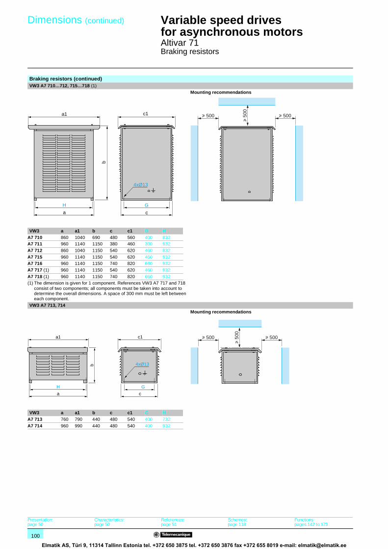
100
Dimensions (continued) 1 Variable speed drivesfor asynchronous motors 1
Altivar 71Braking resistors
Braking resistors (continued)VW3 A7 710…712, 715…718 (1)
Mounting recommendations
VW3 a a1 b c c1 G HA7 710 860 1040 690 480 560 400 832A7 711 960 1140 1150 380 460 300 932
A7 712 860 1040 1150 540 620 460 832
A7 715 960 1140 1150 540 620 460 932A7 716 960 1140 1150 740 820 660 932
A7 717 (1) 960 1140 1150 540 620 460 932
A7 718 (1) 960 1140 1150 740 820 660 932(1) The dimension is given for 1 component. References VW3 A7 717 and 718
consist of two components; all components must be taken into account to determine the overall dimensions. A space of 300 mm must be left between each component.
VW3 A7 713, 714 Mounting recommendations
VW3 a a1 b c c1 G HA7 713 760 790 440 480 540 400 732
A7 714 960 990 440 480 540 400 932
G
c
c1
H
a
b
a1
4xØ13
u 500
u 50
0
u 500
G
c
c1
H
a
b
a1
4xØ13
u 500u 500
u 50
0
Presentation:page 50
Characteristics:page 50
References:page 51
Schemes:page 118
Functions:pages 142 to 173
Elmatik AS, Türi 9, 11314 Tallinn Estonia tel. +372 650 3875 tel. +372 650 3876 fax +372 655 8019 e-mail: [email protected]

101
Dimensions (continued) 1 Variable speed drivesfor asynchronous motors 1
Altivar 71Hoist resistors
Hoist resistorsVW3 A7 801…804, 807…809
Mounting recommendations
VW3 a a1 b c c1 G H ØA7 801 490 452 203.5 153 202 95 470 10
A7 802 420 450 440 480 540 400 392 13
A7 803 580 610 440 480 540 400 552 13A7 804 960 990 440 480 540 400 932 13
A7 807 860 890 440 480 540 400 832 13
A7 808 860 890 690 480 540 400 832 13A7 809 860 890 690 480 450 400 832 13
VW3 A7 805, 806, 810…817 (1)
Mounting recommendations
VW3 a a1 b c c1 G HA7 805 860 1040 1150 540 620 460 832
A7 806 860 1040 1150 740 820 660 832
A7 810 860 1040 1150 540 620 460 832A7 811 960 1140 1150 540 620 460 932
A7 812 960 1140 1150 740 820 660 932
A7 813 (1) 960 1140 1150 540 620 460 932A7 814 (1) 960 1140 1150 540 620 460 932
A7 815 (1) 960 1140 1150 740 820 660 932
A7 816 (1) 960 1140 1150 740 820 660 932A7 817 (1) 960 1140 1700 740 820 660 932
(1) The dimension is given for 1 component. References VW3 A7 813…815 consist of 2 components and references VW3 A7 816 and 817 consist of 3 components; all components must be taken into account to determine the overall dimensions. A space of 300 mm must be left between each component.
G
c
c1
H
a
b
a1
4xØ
u 500u 500
u 50
0
G
c
c1
H
a
b
a1
4xØ13
u 500
u 50
0
u 500
Presentation:page 52
Characteristics:page 52
References:page 53
Schemes:page 118
Functions:pages 142 to 173
Elmatik AS, Türi 9, 11314 Tallinn Estonia tel. +372 650 3875 tel. +372 650 3876 fax +372 655 8019 e-mail: [email protected]

102
Dimensions (continued) 1 Variable speed drivesfor asynchronous motors 1
Altivar 71Network braking units
Network braking unitsVW3 A7 201…205, 231, 232
Mounting recommendations
VW3 a b c G H H1 ØA7 201, 202 270 500 295 260 260 80 7
A7 203…205, A7 231…232
270 580 295 260 340 80 7
VW3 A7 206…208, 233…237 Mounting recommendations
VW3 a b c G H H1 H2 ØA7 206…208 245 700 272 260 440 80 180 7A7 233…237 272 700 295 260 440 80 180 7
H
G= =
H1
b
a
c
4xØ
u 70 u 70
u 15
0u
150
H
G= =
H1
H2
a
b
c
4xØ
u 70 u 70
u 15
0
Presentation:page 62
Characteristics:page 62
References:page 63
Schemes:page 123
Functions:pages 142 to 173
Elmatik AS, Türi 9, 11314 Tallinn Estonia tel. +372 650 3875 tel. +372 650 3876 fax +372 655 8019 e-mail: [email protected]

103
Dimensions (continued) 1 Variable speed drivesfor asynchronous motors 1
Altivar 71Network braking units
Network braking units (continued)VW3 A7 209, 210, 238, 239
Mounting recommendations
VW3 A7 211, 212, 240, 241 Mounting recommendations
VW3 a b c G H H1 H2 ØA7 211, 240 380 937 395 350 320 80 280 8.5A7 212, 241 380 1037 395 350 320 80 280 8.5
320
350= =
280
80
837
380
395
2xØ8,5
4xØ8,5
u 70 u 70
u 15
0
H
G= =
H2
H1
b
a
c
2xØ
4xØ
937
u 70 u 70
u 15
0
Presentation:page 62
Characteristics:page 62
References:page 63
Schemes:page 123
Functions:pages 142 to 173
Elmatik AS, Türi 9, 11314 Tallinn Estonia tel. +372 650 3875 tel. +372 650 3876 fax +372 655 8019 e-mail: [email protected]

104
Dimensions (continued) 1 Variable speed drivesfor asynchronous motors 1
Altivar 71DC chokes, line chokes
(1) The dimension is given for 1 component. References VW3 A4 566 and 567 consist of two components; all components must be taken into account to determine the overall dimensions.
(2) 25 mm minimum.
DC chokesVW3 A4 501…510 VW3 A4 511, 512
VW3 a b c c1 G H ØA4 501 60 103 60 95 50 51 3.5
A4 502 60 103 77 118 50 68 3.5
A4 503 96 134 80 115 80 65 5.5A4 504 96 134 79 115 80 64 5.5
A4 505 96 134 85 120 80 70 5.5
A4 506 96 134 89 120 80 74 5.5A4 507 96 134 99 130 80 84 5.5
A4 508 108 142 112 145 90 97 5.5
A4 509 96 134 89 120 80 74 5.5A4 510 126 171 120 170 105 103 7
Line chokesVW3 A4 551…555 VW3 A4 556
VW3 a b c c1 G G1 H ØA4 551 100 135 55 60 40 60 42 6 x 9A4 552, 553 130 155 85 90 60 80.5 62 6 x 12
A4 554 155 170 115 135 75 107 90 6 x 12
A4 555 180 210 125 165 85 122 105 6 x 12VW3 A4 557 VW3 A4 558…567 (1)
VW3 a b b1 c c1 G G1 H Ø Ø1 Ø2A4 558 280 305 240 210 200 200 125 275 9 9 9
A4 559 280 330 260 210 200 200 125 300 11 9 9
A4 560, 561 320 380 300 210 200 225 150 350 11 9 9A4 562…564 320 380 300 250 230 225 150 350 13 11 11
A4 565 385 440 340 275 250 300 125 400 2 x Ø 13 13 13
A4 566, 567 (1) 320 380 300 250 230 225 150 350 13 11 11
H
4xØ
c
c1
G
a
b
222
240
217 18
191
7548
28014
4xØ7
H
8xØ
c
c1
G
G1
a
b
8xØ11x22
100
180
105
181
270
210
8xØ11x22
142
240
190
230
320
290
50
G
a
H b
G1
c1
(2)
c
b1
Ø
Ø1Ø2
Presentation:pages 66 and 70
Characteristics:pages 68 and 71
References:pages 69 and 72
Schemes:pages 114 to 117
Functions:pages 142 to 173
Elmatik AS, Türi 9, 11314 Tallinn Estonia tel. +372 650 3875 tel. +372 650 3876 fax +372 655 8019 e-mail: [email protected]

105
Dimensions (continued) 1 Variable speed drivesfor asynchronous motors 1
Altivar 71Passive filters
(1) The dimension is given for 1 component.References VW3 A4 614…616, 634…636, 652…654 and 672…674 consist of 2 components and references VW3 A4 617, 637, 655 and 675 consist of 3 components; all components must be taken into account to determine the overall dimensions.
Passive filtersVW3 A4 601…604, 621, 622, 641…644, 661…663
VW3 A4 605…609, 623…627, 645…648, 664…666
VW3 a b c H GA4 605, 606, 623…625, 645, 646, 664, 665 600 220 302 333.5 532.5
A4 607…609, 626, 627, 647, 648, 666 840 220 302 333.5 772.5
VW3 A4 610…617, 628…637, 649…655, 667…675 (1)
VW3 a b cA4 610, 611, 614 (1), 628, 629, 649, 667, 668
830 390 345
A4 612, 615…617 (1), 630, 631, 634 (1),650, 652 (1), 653 (1), 655 (1), 669
900 409 406
A4 613, 632, 635…637 (1), 651, 654 (1), 670, 672 (1), 673 (1), 675 (1)
1070 409 406
A4 633, 671, 674 (1) 1100 409 474
416
440165
135
242
G
aH
c
b
ac
b
Presentation:page 73
Characteristics:page 73
References:pages 74 and 75
Schemes:page 122
Functions:pages 142 to 173
Elmatik AS, Türi 9, 11314 Tallinn Estonia tel. +372 650 3875 tel. +372 650 3876 fax +372 655 8019 e-mail: [email protected]

106
Dimensions (continued) 1 Variable speed drivesfor asynchronous motors 1
Altivar 71Additional EMC input filters
Additional EMC input filtersVW3 A4 401…404 VW3 A4 405, 409
VW3 a b c G H H1 ØA4 401 130 290 40 105 275 – 4.5A4 402 155 324 50 130 309 – 4.5
A4 403 175 370 60 150 355 – 5.5
A4 404 210 380 60 190 365 – 5.5A4 405 230 498.5 62 190 479.5 460 6.6
A4 409 230 498.5 62 190 479.5 460 6.6
VW3 A4 406…408
VW3 a b c G H J ØA4 406 240 522 79 200 502.5 40 6.6
A4 407 240 650 79 200 631 40 6.6
A4 408 320 750 119 280 725 80 9
Mounting the filter under the drive Mounting the filter next to the drive Front view Front view
c
b
G
a
HØ
G
a
HH1
Ø
c
b
c
b
GJ
a
H
Ø
Presentation:page 76
Characteristics:page 77
References:pages 78 and 79
Schemes:page 122
Functions:pages 142 to 173
Elmatik AS, Türi 9, 11314 Tallinn Estonia tel. +372 650 3875 tel. +372 650 3876 fax +372 655 8019 e-mail: [email protected]

107
Dimensions (continued) 1 Variable speed drivesfor asynchronous motors 1
Altivar 71Additional EMC input filters
Additional EMC input filters (continued)VW3 A4 410…413
VW3 a a1 b b1 c G HA4 410 800 302 261 219 139 120 235A4 411 800 302 261 219 139 120 235
A4 412 900 352 281 239 174 145 255
A4 413 1000 401 301 259 164 170 275
IP 30 protection kits for filters VW3 A4 410…413
VW3 a a1 b b1A9 601 1200 800 310 270
A9 602 1400 1000 350 310
H b
a
a1
GG= =c10
b1
6xØ12
9090b
170 3535
=a1
a
=
b1
Presentation:page 76
Characteristics:page 77
References:pages 78 and 79
Schemes:page 122
Functions:pages 142 to 173
Elmatik AS, Türi 9, 11314 Tallinn Estonia tel. +372 650 3875 tel. +372 650 3876 fax +372 655 8019 e-mail: [email protected]

108
Dimensions (continued) 1 Variable speed drivesfor asynchronous motors 1
Altivar 71Motor chokes
Motor chokes (1)
VW3 A5 101, 102 Mounting recommendations (2)
VW3 a b c G H ØA5 101 190 210 90 170 45 8 x 12
A5 102 200 235 130 170 48 8 x 12
VW3 A5 103 (3)
Mounting recommendations (2)
VW3 A5 104, 105 (4)
VW3 a b c G H ØA5 104 170 250 100 150 75 9
A5 105 210 250 110 175 75 9 x 13(1) It is absolutely essential that the motor chokes are mounted on a metal support (grille, frame, etc.)(2) Because of the magnetic field, it is very important to follow the mounting recommendations provided.(3) Because of heat dissipation, this choke must be mounted vertically. (4) References VW3 A5 104 and 105 consist of 3 components.
H
c
G
a
b
4xØ
u 10
0
u 100 u 100u 100 u 100
180
234
226
79
126
101
4xØ8x13
Ø9
u 100
u 10
0u
100
Ga
b
H
c
4xØ
u 20
Presentation:pages 80 and 81
Characteristics:page 81
References:pages 82 and 83
Schemes:page 122
Functions:pages 142 to 173
Elmatik AS, Türi 9, 11314 Tallinn Estonia tel. +372 650 3875 tel. +372 650 3876 fax +372 655 8019 e-mail: [email protected]

109
Dimensions (continued) 1 Variable speed drivesfor asynchronous motors 1
Altivar 71Motor chokes
Motor chokes (continued) (1)
VW3 A5 106…108 (2)
VW3 a b c G H ØA5 106 (1) 245 250 200 225 175 9
A5 107 (1) 315 250 210 275 175 9
A5 108 (1) 370 250 230 325 200 9
IP 20 protection kits for chokes VW3 A5 104…108
VW3 a b G H ØA9 612 800 600 530 554 10 x 15
A9 613 1200 800 800 757 10 x 15
(1) It is absolutely essential that the motor chokes are mounted on a metal support (grille, frame, etc.)(2) References VW3 A5 106…108 consist of 3 components.
Hc
4xØ
G
a
b
u 20
331 G200a
H b4xØ
Presentation:pages 80 and 81
Characteristics:page 81
References:pages 82 and 83
Schemes:page 122
Functions:pages 142 to 173
Elmatik AS, Türi 9, 11314 Tallinn Estonia tel. +372 650 3875 tel. +372 650 3876 fax +372 655 8019 e-mail: [email protected]

110
Dimensions (continued) 1 Variable speed drivesfor asynchronous motors 1
Altivar 71Sinus filters
(1) Sinus filters emit considerable heat and must not be placed underneath the drive.
Sinus filters (1)
VW3 A5 201…206 Mounting recommendations
VW3 a b c G H ØA5 201 120 335 160 100 280 6.6
A5 202 120 375 190 100 320 6.6
A5 203 150 470 240 120 380 6.6A5 204 210 650 280 160 530 8.6
A5 205 250 780 360 200 650 8.6
A5 206 300 930 415 220 780 11VW3 A5 207
Mounting recommendations
4xØ
c G
a
H b
u 300u 300
u 20
0
u 30
0
u 200 u 200
194
290
370
420
500
4xØ11x15 u 200u 200
u 20
0
u 200 u 200
Presentation:pages 80 and 84
Characteristics:page 84
References:page 85
Schemes:page 122
Functions:pages 142 to 173
Elmatik AS, Türi 9, 11314 Tallinn Estonia tel. +372 650 3875 tel. +372 650 3876 fax +372 655 8019 e-mail: [email protected]

111
Dimensions (continued) 1 Variable speed drivesfor asynchronous motors 1
Altivar 71Sinus filters
(1) Sinus filters emit considerable heat and must not be placed underneath the drive.
Sinus filters (1)
VW3 A5 208…211 Mounting recommendations
VW3 a b c G H Ø Ø1A5 208 420 500 345 370 231 11 x 15 11
A5 209 480 600 340 430 238 13 x 18 11
A5 210 480 710 370 430 258 13 x 18 14A5 211 620 930 500 525 352 13 x 22 4 x Ø 11
G
a
b
H
c
4xØ
Ø1
Ø1
u 200u 200
u 20
0
u 200 u 200
Presentation:pages 80 and 84
Characteristics:page 84
References:page 85
Schemes:page 122
Functions:pages 142 to 173
Elmatik AS, Türi 9, 11314 Tallinn Estonia tel. +372 650 3875 tel. +372 650 3876 fax +372 655 8019 e-mail: [email protected]

112
Schemes 1 Variable speed drivesfor asynchronous motors 1
Altivar 71Safety requirements
(1) Redundant: consists of mitigating the effects of failure of one component by means of the correct operation of another, assuming that faults do not occur simultaneously on both.
“Power Removal” safety functionThe Altivar 71 drive integrates the “Power Removal” safety function which prohibits unintended equipment operation. The motor no longer produces torque.
This safety function:b complies with standard for safety of machinary EN 954-1, category 3b complies with standard for functional safety IEC/EN 61508, SIL2 capability (Functional safety of electrical/electronic/programmable electronic safety-related systems) The SIL (Safety Integrity Level) capability depends on the connection diagram for the drive and for the safety function. Failure to observe the setup recommendations could inhibit the SIL capability of the “Power Removal” safety function. b complies with definition of the draft product standard IEC/EN 61800-5-2 for both stop functions:v Safe Torque Off (“STO”)v Safe Stop 1 (“SS1”)
The “Power Removal” safety function has a redundant electronic architecture (1) which is monitored continuously by a diagnostics function.
This SIL2 and category 3 level of safety function is certified as conforming to these standards by the INERIS certification body under a program of voluntary certification.
Categories relating to safety according to EN 954-1Categories Basic safety principle Control system
requirementsBehaviour in the event of a fault
B Selection of components that conform to relevant standards.
Control in accordance with good engineering practice.
Possible loss of safety function.
1 Selection of components and basic safety principles.
Use of tried and tested components and proven safety principles.
Possible loss of safety function, but with less probability of this than with B
2 Selection of components and basic safety principles.
Cyclic testing. The test intervals must be suited to the machine and its applications.
Fault detected at each test.
3 Structure of the safety circuits.
A single fault must not cause loss of the safety function. This single fault must be detected if reasonably practicable.
Safety function ensured, except in the event of an accumulation of faults.
4 Structure of the safety circuits.
A single fault must not cause loss of the safety function. This fault must be detected at or before the next demand on the safety function. An accumulation of faults must not cause loss of the safety function.
Safety function always ensured.
The machinary manufacturer is responsible for selecting the safety category. The category depends of the level of risk factors given in standard EN 954-1.
Safety Integrity Levels (SIL) according to standard IEC/EN 61508
SIL1 according to standard IEC/EN 61508 is comparable with category 1 according to EN 954-1 (SIL1: means probability of undetected dangerous failure per hour between 10-5 and 10-6).SIL2 according to standard IEC/EN 61508 is comparable with category 3 according to EN 954-1 (SIL1: means probability of undetected dangerous failure per hour between 10-6 and 10-7).
Presentation:pages 4 to 7
Characteristics:pages 8 to 13
References:pages 18 and 19
Dimensions:pages 90 to 111
Functions:pages 142 to 173
Elmatik AS, Türi 9, 11314 Tallinn Estonia tel. +372 650 3875 tel. +372 650 3876 fax +372 655 8019 e-mail: [email protected]

113
Schemes (continued) 1 Variable speed drivesfor asynchronous motors 1
Altivar 71Safety requirements
“Power Removal” safety function considerationsThe “Power Removal” safety function cannot be considered as a means of electrical disconnection of the motor (no electrical isolation); if necessary, a Vario switch disconnector must be used.The “Power Removal” safety function is not designed to overcome any malfunction in the drive process control or application functions.The output signals available on the drive must not be considered as safety related signals (e.g. “Power Removal” active); these are Preventa-type safety module outputs which must be integrated into a safety related control/command circuit.
The schemes on the following pages take into account conformity with standard IEC/EN 60204-1 which defines three categories of stops:b Category 0: stopping by immediate removal of the power from the machine actuators (i.e. an uncontrolled stop).b Category 1: a controlled stop with power available to the machine actuators to achieve the stop and then removal of power when the stop is achieved.b Category 2: a controlled stop with power left available to the machine actuators.
Connection diagrams and applicationsConformity with category 1 of standard EN 954-1 and level SIL1 according to standard IEC/EN 61508
Use of the connection diagrams on pages 114 and 115 which use a line contactor or a Vario switch disconnector between the drive and the motor. In this case, the “Power Removal” safety function is not used and the motor stops in accordance with category 0 of standard IEC/EN 60204-1.
Conformity with category 3 of standard EN 954-1 and level SIL2 according to standard IEC/EN 61508
The connection diagrams use the “Power Removal” safety function of the Altivar 71 drive combined with a Preventa safety module which monitors the Emergency stop circuits.
Machines with short freewheel stopping times (low inertia or high resistive torque, see page 116).When the activation command is given on the PWR input with the controlled motor, the motor power supply is immediately switched off and the motor stops according to category 0 of standard IEC/EN 60204-1.Restarting is not permitted even when the activation command is given after the motor has come to a complete stop (“STO”).This safe stop is maintained while the PWR input remains activated.
This diagram must also be used for hoisting applications.On a “Power Removal” command, the drive requires the brake to be engaged, but a Preventa safety module contact must be inserted in series in the brake control circuit to engage it safely when a request is made to activate the “Power Removal” safety function.
Machines with long freewheel stopping times (high inertia or low resistive torque, see page 117).When the activation command is given, deceleration of the motor controlled by the drive is first requested, then, following a time delay controlled by a Preventa-type safety relay which corresponds to the deceleration time, the “Power Removal” safety function is activated by the PWR input. The motor stops according to category 1 of standard IEC/EN 60204-1 (“SS1”).
Periodic testThe “Power Removal” safety input must be activated at least once a year for preventive maintenance purposes. The drive must be switched off before preventive maintenance takes place, and then powered up again. If during testing the power supply to the motor is not switched off, safety integrity is no longer assured for the “Power Removal” safety function. The drive must therefore be replaced to ensure the operational safety of the machine or of the process system.
Presentation:pages 4 to 7
Characteristics:pages 8 to 13
References:pages 18 and 19
Dimensions:pages 90 to 111
Functions:pages 142 to 173
Elmatik AS, Türi 9, 11314 Tallinn Estonia tel. +372 650 3875 tel. +372 650 3876 fax +372 655 8019 e-mail: [email protected]

114
Schemes (continued) 1 Variable speed drivesfor asynchronous motors 1
Altivar 71
Schemes conforming to standards EN 954-1 category 1, IEC/EN 61508 SIL1 capability,in stopping category 0 according to IEC/EN 60204-1ATV 71ppppM3, ATV 71ppppM3X, ATV 71ppppN4 ATV 71H075M3…HU75M3 3-phase power supply with upstream breaking via contactor Power section for single phase power supply
Note: All terminals are located at the bottom of the drive. Fit interference suppressors to all inductive circuits near the drive or connected on the same circuit, such as relays, contactors, solenoid valves, fluorescent lighting, etc.Components for use with the Altivar (for a complete list of references, see our “Motor starter solutions. Power control and protection components” specialist catalogue).Reference Description
A1 ATV 71 drive, see pages 18 and 19
KM1 Contactor, see motor starters pages 128 to 131L1 DC choke, see page 69
Q1 Circuit-breaker, see motor starters pages 128 to 131
Q2 GV2 L rated at twice the nominal primary current of T1Q3 GB2 CB05
S1, S2 XB4 B or XB5 A pushbuttons
T1 100 VA transformer 220 V secondary(1) Line choke (single phase or 3-phase), see page 72.(2) For ATV 71HC40N4 drives combined with a 400 kW motor and ATV 71HC50N4, see page 118.(3) Fault relay contacts. Used for remote signalling of the drive status.(4) Connection of the common for the logic inputs depends on the positioning of the SW1 switch: see schemes on page 118.(5) DC choke as an option for ATV 71HpppM3, ATV 71HD11M3X…HD45M3X, ATV 71H075N4…HD75N4. Connected in place of the strap between the PO and
PA/+ terminals. For ATV 71HD55M3X, HD75M3X, ATV 71HD90N4…HC50N4 drives, the choke is supplied with the drive; the customer is responsible for connecting it.
(6) Software-configurable current (0…20 mA) or voltage (0…10 V) analog input.
PA
/+
W/T
3
PO
PC
/–
U/T
1
V/T
2
AI2
AI1
–
AO
1
CO
M
CO
M
+ 1
0
AI1
+
R/L
1
S/L
2
T/L
3
R1A
R1C
R1B LI
1
LI2
LI3
LI4
+ 2
4
PW
R
U1
W1
V1
M 3
X-Y mA
L1
0…10 V
(4)
(6)
(3) (2) (2) (2)
(5)
(1)
LI5
LI6
T1KM1
A2A1
3 4 5 6
Q2
ATV 71Hppppp
1 2
R1A R1C 13 14
Q1
2 4 6
KM1
Q21 2 Q3 S2 S1
KM1
1 3 5
A1
A1
2 4 6
1 3 5
R2A
R2C
Reference potentiometer
or
(1)
Q1
2 4 6
KM1
1 3 5
2 4
1 3
W/T
3
U/T
1
V/T
2R
/L1
S/L
2A1
U1
W1
V1
M 3
To 1/Q2
To 3/Q2
Presentation:pages 4 to 7
Characteristics:pages 8 to 13
References:pages 18 and 19
Dimensions:pages 90 to 111
Functions:pages 142 to 173
Elmatik AS, Türi 9, 11314 Tallinn Estonia tel. +372 650 3875 tel. +372 650 3876 fax +372 655 8019 e-mail: [email protected]

115
Schemes (continued) 1 Variable speed drivesfor asynchronous motors 1
Altivar 71
Schemes conforming to standards EN 954-1 category 1, IEC/EN 61508 SIL1 capability,in stopping category 0 according to IEC/EN 60204-1 (continued)ATV 71ppppM3, ATV 71ppppM3X, ATV 71ppppN4 ATV 71H075M3…HU75M3 3-phase power supply with downstream breaking via switch disconnector Power section for single phase power supply
Note: All terminals are located at the bottom of the drive. Fit interference suppressors to all inductive circuits near the drive or connected on the same circuit, such as relays, contactors, solenoid valves, fluorescent lighting, etc.
Components for use with the Altivar (for a complete list of references, see our “Motor starter solutions. Power control and protection components” specialist catalogue).
Reference DescriptionA1 ATV 71 drive, see pages 18 and 19L1 DC choke, see page 69
Q1 Circuit-breaker, see motor starters pages 128 to 131
Q2 Switch disconnector (Vario) (1) Line choke (single phase or 3-phase), see page 72.(2) For ATV 71HC40N4 drives combined with a 400 kW motor and ATV 71HC50N4, see page 118.(3) Fault relay contacts. Used for remote signalling of the drive status.(4) Connection of the common for the logic inputs depends on the positioning of the SW1 switch: see schemes on page 118.(5) DC choke as an option for ATV 71HpppM3, ATV 71HD11M3X…HD45M3X, ATV 71H075N4…HD75N4. Connected in place of the strap between the PO and
PA/+ terminals. For ATV 71HD55M3X, HD75M3X, ATV 71HD90N4…HC50N4 drives, the choke is supplied with the drive; the customer is responsible for connecting it.
(6) Software-configurable current (0…20 mA) or voltage (0…10 V) analog input.
PA
/+
W/T
3
PO
PC
/–
U/T
1
V/T
2
AI2
AI1
–
AO
1
CO
M
CO
M
+ 1
0
AI1
+
R/L
1
S/L
2
T/L
3
R1A
R1C
R1B LI
1
LI2
LI3
LI4
+ 2
4
PW
R
X-Y mA
L1
0…10 V
(4)
(6)
(3) (2) (2) (2)
(5)
(1)LI
5
LI6
ATV 71Hppppp
Q1
2 4 6
1 3 5
A1
R2A
R2C
1/L1
2/T
1
3/L2
4/T
2
5/L3
6/T
3
Q2
U1
W1
V1
M 3
Reference potentiometer
or
(1)
Q1
2 4 6
1 3 5
W/T
3
U/T
1
V/T
2R
/L1
S/L
2A1
1/L1
2/T
1
3/L2
4/T
2
5/L3
6/T
3
Q2
U1
W1
V1
M 3
Presentation:pages 4 to 7
Characteristics:pages 8 to 13
References:pages 18 and 19
Dimensions:pages 90 to 111
Functions:pages 142 to 173
Elmatik AS, Türi 9, 11314 Tallinn Estonia tel. +372 650 3875 tel. +372 650 3876 fax +372 655 8019 e-mail: [email protected]

116
Schemes (continued) 1 Variable speed drivesfor asynchronous motors 1
Altivar 71
Schemes conforming to standards EN 954-1 category 3, IEC/EN 61508 SIL2 capability,in stopping category 0 according to IEC/EN 60204-1ATV 71HpppM3, ATV 71HpppM3X, ATV 71HpppN4 ATV 71H075M3…HU75M3 3-phase power supply, low inertia machine, vertical movement Power section for single phase power
supply
Note: All terminals are located at the bottom of the drive. Fit interference suppressors to all inductive circuits near the drive or connected on the same circuit, such as relays, contactors, solenoid valves, fluorescent lighting, etc.
Components for use with the Altivar (for a complete list of references, see our “Motor starter solutions. Power control and protection components” and “Preventa safety solutions” specialist catalogues).
Reference DescriptionA1 ATV 71 drive, see pages 18 and 19
A2 Preventa XPS AC safety module for monitoring emergency stops and switches. One safety module can manage the “Power Removal” function for several drives on the same machine.
F1 Fuse
L1 DC choke, see page 69Q1 Circuit-breaker, see motor starters pages 128 to 131
S1 Emergency stop button with 2 contacts
S2 XB4 B or XB5 A pushbutton(1) Power supply: c or a 24 V, a 48 V, a 115 V, a 230 V.(2) S2: resets XPS AC module on power-up or after an emergency stop. ESC can be used to set external starting conditions.(3) Requests freewheel stopping of the movement and activates the “Power Removal” safety function.(4) Line choke (single phase or 3-phase), see page 72.(5) The logic output can be used to signal that the machine is in a safe stop state.(6) For ATV 71HC40N4 drives combined with a 400 kW motor and ATV 71HC50N4, see page 118.(7) Fault relay contacts. Used for remote signalling of the drive status.(8) Connection of the common for the logic inputs depends on the positioning of the SW1 switch: see schemes on page 118.(9) Standardized coaxial cable, type RG174/U according to MIL-C17 or KX3B according to NF C 93-550, external diameter 2.54 mm, maximum length 2 m. The
cable shielding must be earthed.(10)Optional DC choke for ATV 71HppppM3, ATV 71HD11M3X…HD45M3X, ATV 71H075N4…HD75N4. Connected in place of the strap between the PO and
PA/+ terminals. For ATV 71HD55M3X, HD75M3X, ATV 71HD90N4…HC50N4 drives, the choke is supplied with the drive; the customer is responsible for connecting it.
(11)Software-configurable current (0…20 mA) or voltage (0…10 V) analog input.
PA
/+
W/T
3
PO
PC
/–
U/T
1
V/T
2
AI2
AI1
–
AO
1
CO
M
CO
M
+ 1
0
AI1
+
R/L
1
S/L
2
T/L
3
R1A
R1C
R1B LI
1
LI2
LI3
LI4
+ 2
4
PW
R
X-Y mA
L1
0…10 V
(8) (9)
(5)
(11)
(7) (6) (6) (6)
(10)
(4)
LI5
LI6
ATV 71Hppppp
Q1
2 4 6
1 3 5
A1
R2A
R2C
A2 A1 Y1 13 23 33 Y43
14 24 34 Y44
+
–
A248 V, 115 V, 230 V
PE
K1
K1
K2
K2
S2
ESC
T
Y2
S1
L1 (+)(1)
(3)
(2)
(2)
N (–)
F1
XPS AC
U1
W1
V1
M 3 Reference
potentiometeror
Logic
(4)
Q1
2 4 6
1 3 5
W/T
3
U/T
1
V/T
2R
/L1
S/L
2A1
U1
W1
V1
M 3
Presentation:pages 4 to 7
Characteristics:pages 8 to 13
References:pages 18 and 19
Dimensions:pages 90 to 111
Functions:pages 142 to 173
Elmatik AS, Türi 9, 11314 Tallinn Estonia tel. +372 650 3875 tel. +372 650 3876 fax +372 655 8019 e-mail: [email protected]

117
Schemes (continued) 1 Variable speed drivesfor asynchronous motors 1
Altivar 71
Schemes conforming to standards EN 954-1 category 3, IEC/EN 61508 capability SIL2,in stopping category 1 according to IEC/EN 60204-1ATV 71HpppM3, ATV 71HpppM3X, ATV 71HpppN4 ATV 71H075M3…HU75M3 3-phase power supply, high inertia machine Power section for single phase power
supply
Note: All terminals are located at the bottom of the drive. Fit interference suppressors to all inductive circuits near the drive or connected on the same circuit, such as relays, contactors, solenoid valves, fluorescent lighting, etc.
Components for use with the Altivar (for a complete list of references, see our “Motor starter solutions. Power control and protection components” and “Preventa safety solutions” specialist catalogues).
Reference DescriptionA1 ATV 71 drive, see pages 18 and 19
A2 (6) Preventa XPS AT safety module for monitoring emergency stops and switches. One safety module can manage the “Power Removal” function for several drives on the same machine, but the time delay must be adjusted on the drive controlling the motor that requires the longest stopping time.
F1 Fuse
L1 DC choke, see page 69
Q1 Circuit-breaker, see motor starters pages 128 to 131S1 Emergency stop button with 2 contacts
S2 XB4 B or XB5 A pushbutton
(1) Power supply: c or a 24 V, a 115 V, a 230 V.(2) Requests controlled stopping of the movement and activates the “Power Removal” safety function.(3) Line choke (single phase or 3-phase), see page 72.(4) S2: resets XPS AC module on power-up or after an emergency stop. ESC can be used to set external starting conditions.(5) The “N/C” contact can be used to signal that the machine is in a safe stop state.(6) For stopping times requiring more than 30 seconds in category 1, use a Preventa XPS AV safety module which can provide a maximum time delay of
300 seconds.(7) For ATV 71HC40N4 drives combined with a 400 kW motor and ATV 71HC50N4, see page 118.(8) Fault relay contacts. Used for remote signalling of the drive status.(9) Connection of the common for the logic inputs depends on the positioning of the SW1 switch: see schemes on page 118.(10)Standardized coaxial cable, type RG174/U according to MIL-C17 or KX3B according to NF C 93-550, external diameter 2.54 mm, maximum length 2 m. The
cable shielding must be earthed.(11)Logic inputs LI1 and LI2 must be assigned to the direction of rotation: LI1 in the forward direction and LI2 in the reverse direction.(12)Optional DC choke for ATV 71HppppM3, ATV 71HD11M3X…HD45M3X, ATV 71H075N4…HD75N4. Connected in place of the strap between the PO and
PA/+ terminals. For ATV 71HD55M3X, HD75M3X, ATV 71HD90N4…HC50N4 drives, the choke is supplied with the drive; the customer is responsible for connecting it.
(13)Software-configurable current (0…20 mA) or voltage (0…10 V) analog input.
PA
/+
W/T
3
PO
PC
/–
U/T
1
V/T
2
AI2
AI1
–
AO
1
CO
M
CO
M
+ 1
0
AI1
+
R/L
1
S/L
2
T/L
3
R1A
R1C
R1B LI
1
LI2
LI3
LI4
+ 2
4
PW
R
X-Y mA
L1
0…10 V
(9) (10)
(11)
(5) (6)
(13)
(8) (7) (7) (7)
(12)
(3)
LI5
LI6
ATV 71Hppppp
Q1
2 4 6
1 3 5
A1
R2A
R2C
A2 A1 B1S21 13 23 33 41
14 24 34Y1 Y2 Y3 Y4 Y5
57 67
42 58 68
S11
S33
S12 S22
(+)(–)
A2 PE
0…30 s
N (–)
L1 (+) (1)
F1
S2 ESC(4) (4)
XPS AT
U1
W1
V1
M 3
S1(2)
Reference potentiometer
or
(3)
Q1
2 4 6
1 3 5
W/T
3
U/T
1
V/T
2R
/L1
S/L
2A1
U1
W1
V1
M 3
Presentation:pages 4 to 7
Characteristics:pages 8 to 13
References:pages 18 and 19
Dimensions:pages 90 to 111
Functions:pages 142 to 173
Elmatik AS, Türi 9, 11314 Tallinn Estonia tel. +372 650 3875 tel. +372 650 3876 fax +372 655 8019 e-mail: [email protected]

118
Schemes (continued) 1 Variable speed drivesfor asynchronous motors 1
Altivar 71
Power terminal connections for ATV 71HC40N4 combined with a 400 kW motor and ATV 71HC50N4
(1) For control section connections, see pages 114 to 117.(2) Line choke, see page 72.
VW3 A7 7pp braking resistors or VW3 A7 8pp hoisting resistors, VW3 A7 1pp braking unitsATV 71HpppM3, HpppM3X, ATV 71H075N4…HC16N4
ATV 71HC20N4…HC50N4
Components for use with the AltivarReference Description
A1 ATV 71 drive, see pages 18 and 19A2 Braking unit, if using a braking resistor or a hoisting resistor, for ATV 71HC20N4…HC50N4, see pages 48 and 49
L1 DC choke provided as standard with the drive
Braking resistor See pages 50 to 53
(1) Thermal overload relay if there is no temperature controlled switch in the sequence.
Examples of recommended schemesLogic inputs
The SW1 switch is used to adapt operation of the logic inputs (LI) to the PLC output technology:b Position the switch on Supply (factory setting) if using PLC outputs with PNP transistorsb Position the switch on Int Sink or Ext Sink if using PLC outputs with NPN transistors
Internal power supplySwitch on “Supply” position Switch on “Int Sink” position
External power supplySwitch on “Supply” position Switch on “Ext Sink” position
L1A
L2A
L3A
L1B
L2B
L3B
(2) (2)
To circuit-breaker (1)
A1
PA
/+
PB
Braking resistor
A1
A2
PA
/+
PO
PC
/–
+–
L1
(1)PB
PA
TH Braking resistor
Braking unit
ATV 71HpppppSW1
Sink
+24
LI1
LI2
LI3
LI4
LI5
LI6
0 V
SW2
PTC LI
SupplyExt. Int.
ATV 71Hppppp
+24
LI1
LI2
LI3
LI4
LI5
LI6
0 V
SW1
Sink
SW2
PTC LI
SupplyExt. Int.
ATV 71HpppppSW1
Sink
+24
LI1
LI2
LI3
LI4
LI5
LI6
0 V
+ 24 V0 V
SW2
LIPTC
SupplyExt. Int.
24 V c supply
ATV 71HpppppSW1
Sink
+24
LI1
LI2
LI3
LI4
LI5
LI6
0 V
+ 24 V0 V
SW2
LIPTC
SupplyExt. Int.
24 V c supply
Presentation:pages 4 to 7
Characteristics:pages 8 to 13
References:pages 18 and 19
Dimensions:pages 90 to 111
Functions:pages 142 to 173
Elmatik AS, Türi 9, 11314 Tallinn Estonia tel. +372 650 3875 tel. +372 650 3876 fax +372 655 8019 e-mail: [email protected]

119
Schemes (continued) 1 Variable speed drivesfor asynchronous motors 1
Altivar 71
Examples of recommended schemes (continued)Input for PTC probes
The SW2 switch is used to operate the LI6 input: b As a logic input by setting the SW2 switch to LI (factory setting)b Or for protecting the motor via PTC probes by setting the SW2 switch to PTC
2-wire control and jog operation (JOG) 3-wire control and jog operation (JOG)
Unipolar speed reference Bipolar speed reference Requires a VW3 A3 201 or VW3 A3 202 I/O extension card
Speed reference using axis control Separate control power supply The separate control card can be powered by an external 24 V c supply
Analog input configured for voltage Analog input configured for currentExternal 0…10 V External + 10 V 0-20 mA, 4-20 mA, X-Y mA
ATV 71Hppppp
LI6
0 V
SW2
LIPTC
A1
Motor
ATV 71H
+ 2
4
LI LI LI
Forward Reverse JOG
ATV 71H
+ 2
4
LI1
LI2
LI3
LI4
Stop Forward Reverse
JOGforward
JOGreverse
ATV 71H
AI1
–
CO
M
+10
AI1
+
Reference potentiometer
ATV 71Hppppp
AI1
–
CO
M
+10
AI1
+
VW3 A3 20p
– 10
Reference potentiometer
ATV 71H
AI1
–
CO
M
AI1
+
0 V + –
Reference ± 10 V
Axis control
0 V
P 2
4
ATV 71H
+ 24 V
0 V
24 V c supply
AI2
CO
M
0…10 V
ATV 71H
AI2
CO
M
+ 10 V
ATV 71H
Speed reference potentiometer 2.2 to 10 kΩ
AI2
CO
M
ATV 71H
Supply0-20 mA4-20 mAX-Y mA
Presentation:pages 4 to 7
Characteristics:pages 8 to 13
References:pages 18 and 19
Dimensions:pages 90 to 111
Functions:pages 142 to 173
Elmatik AS, Türi 9, 11314 Tallinn Estonia tel. +372 650 3875 tel. +372 650 3876 fax +372 655 8019 e-mail: [email protected]

120
Schemes (continued) 1 Variable speed drivesfor asynchronous motors 1
Altivar 71
VW3 A3 201 and VW3 A3 202 I/O extension cardsLogic I/O
The SW4 switch is used to adapt operation of the logic inputs (LI) to the PLC output technology:b Position the switch on Supply (factory setting) if using PLC outputs with PNP transistorsb Position the switch on Int Sink or Ext Sink if using PLC outputs with NPN transistorsInternal power supply
Switch on “Supply” position Switch on “Int Sink” position
External power supplySwitch on “Supply” position Switch on “Ext Sink” position
Analog I/O (only on VW3 A3 202 extended I/O card)
(1) Software-configurable current (0-20 mA) or voltage (0…10 V) analog input.(2) Software-configurable current (0-20 mA) or voltage (± 10 V or 0…10 V) analog outputs, independent selection possible for each output via switch).(3) R: add a resistor if the input voltage of the pulse train is greater than 5 V.
Recommended values:
Input voltageV
ResistanceΩ
12 510
15 91024 1300
+24
0 V
LIp
LOp
LOp
RpA
RpC
RpB
CLO
VW3 A3 20p
THp
+
THp
–
SW4
SinkSupplyExt. Int.
Motor
+24
0 V
LIp
LOp
LOp
RpA
RpC
RpB
CLO
THp
+
THp
–
SW4
Sink
VW3 A3 20p
SupplyExt. Int.
Motor
+24
0 V
RpA
RpC
RpB
CLO
SW4
Sink
+ 24 V
0 V
LIp
LOp
LOp
THp
+
THp
–
VW3 A3 20p
SupplyExt. Int.
Motor
24 V c supply
+24
0 V
RpA
RpC
RpB
CLO
SW4
Sink
+ 24 V
0 V
LIp
LOp
LOp
THp
+
THp
–
VW3 A3 20p
SupplyExt. Int.
Motor
24 V c supply
AI3
+
AI3
–
AI4
AO
2 (1
)
AO
3 (1
)
CO
M
CO
M
RP
0 V
X-Y mA R
0…10 V (1)
(2) (3)
VW3 A3 202
Supply0-20 mA4-20 mAX-Y mA
or
Presentation:pages 4 to 7
Characteristics:pages 8 to 13
References:pages 18 and 19
Dimensions:pages 90 to 111
Functions:pages 142 to 173
Elmatik AS, Türi 9, 11314 Tallinn Estonia tel. +372 650 3875 tel. +372 650 3876 fax +372 655 8019 e-mail: [email protected]

121
Schemes (continued) 1 Variable speed drivesfor asynchronous motors 1
Altivar 71
(1) Only if the power consumption is less than 200 mA; otherwise use an external power supply.
VW3 A3 401 to VW3 A3 407 encoder interface cardsClosed loop control
Wiring the encoder
VW3 A3 501 programmable “Controller Inside” cardCard powered by the drive (1)
Card powered by external power supply
A A –
B B –
0 V
s
+ V
s
A
A – B
B –
0 V
s
+ V
s
VW3 A3 40p
Encoder
SW1
Sink
24 V
LI5p
LO5p
LO5p
AI5
1
AI5
2
CO
M
VW3 A3 501
0-20 mA 0-20 mA
ATV 71Hppppp
+ 2
4 VSupply
Ext. Int.
CO
M
24 V
+ 24 V
0 V
LI5p
LO5p
LO5p
AI5
1
AI5
2
CO
M
AO
51
AO
52
CO
M
VW3 A3 501
0-20 mA 0-20 mA0-20 mA 0-20 mA
24 V c supply
Presentation:pages 4 to 7
Characteristics:pages 8 to 13
References:pages 18 and 19
Dimensions:pages 90 to 111
Functions:pages 142 to 173
Elmatik AS, Türi 9, 11314 Tallinn Estonia tel. +372 650 3875 tel. +372 650 3876 fax +372 655 8019 e-mail: [email protected]

122
Schemes (continued) 1 Variable speed drivesfor asynchronous motors 1
Altivar 71
(1) Line choke compulsory for ATV 71HU40M3X…HU75M3X.
VW3 A4 6pp passive filters
VW3 A4 4pp additional EMC input filters3-phase power supply, 3-phase filter Single phase power supply, 3-phase filter
VW3 A5 ppp output filtersVW3 A5 1pp motor chokes VW3 A5 2pp sinus filters
X2.
1
X2.
2
X2.
3
X1.
1
X1.
2
X1.
3
L1 L2 L3
VW3 A4 6pp
ATV 71HpppN4
L'1
L'2
L'3
L1 L2 L3
L1 L2 L3
VW3 A3 4pp
ATV 71Hppppp
VW3 A3 4pp
ATV 71Hppppp
L'1
L'2
L1 L2
L1 L2
L'3
L3L3
(1)
U V W
U V WPE
PE
UT
/1
VT
/2
WT
/3
VW3 A5 1pp
ATV 71Hppppp
U1
W1
V1
M 3
U V W
U V WPE
PE
UT
/1
VT
/2
WT
/3
VW3 A5 2pp
ATV 71Hppppp
U1
W1
V1
M 3
Presentation:pages 4 to 7
Characteristics:pages 8 to 13
References:pages 18 and 19
Dimensions:pages 90 to 111
Functions:pages 142 to 173
Elmatik AS, Türi 9, 11314 Tallinn Estonia tel. +372 650 3875 tel. +372 650 3876 fax +372 655 8019 e-mail: [email protected]

123
Schemes (continued) 1 Variable speed drivesfor asynchronous motors 1
Altivar 71
(1) Additional EMC input filter if necessary, see page 78.(2) Line choke recommended, see page 72.(3) For ATV 71HC40N4 drives combined with a 400 kW motor and ATV 71HC50N4, see page 118.
Network braking unit
Components for use with the Altivar (for a complete list of references, see our “Motor starter solutions. Power control and protection components” specialist catalogue).
Reference DescriptionA1 ATV 71 drive, see pages 18 and 19
A2 Network braking unit (see page 62)
F1 2 A fuse, a 230 VF2…F4 For fuses, see reference tables on pages 63 and 64.
Q1 Circuit-breaker DDR 300 mA. Protects against earth leakage faults. Rating: see motor starters on pages 128 to 131
+ 2
4
PA/+PC/–
+–
U1
W1
V1
M 3
ATV 71Hppppp
Q1
2 4 6
KM1
L1L2L3NPE
1 3 5
X2
A1
A2
2 4 6
1 3 5
12 34
L1 L2 L3 L1
L1
N230 V
N
PE
W/T
3
U/T
1
LI1
V/T
2
R/L
1
S/L
2
T/L
3
R1A
R1C
R1B
R2A
R2C
(1)
F2
F3
F4
(2)
(3) (3) (3)
F1
Relay
Presentation:pages 4 to 7
Characteristics:pages 8 to 13
References:pages 18 and 19
Dimensions:pages 90 to 111
Functions:pages 142 to 173
Elmatik AS, Türi 9, 11314 Tallinn Estonia tel. +372 650 3875 tel. +372 650 3876 fax +372 655 8019 e-mail: [email protected]

124
Schemes (continued) 1 Variable speed drivesfor asynchronous motors 1
Altivar 71
Drives combined with a braking unit and wired onto the same DC busATV 71HC20N4…HC50N4
(1) Thermal overload relay if there is no temperature controlled switch in the sequence.
Drive powered by external DC power supplyATV 71HD18M3X…HD45M3X, ATV 71HD22N4…HD75N4
For drivesA1, A2
DC power supply Braking resistors R1, R2 Contactors (3) KM1, KM2 Value Reference
A ΩATV 71HD18M3X 135 5 VW3 A7 707 LC1 D32ppATV 71HD22M3X 157 5 VW3 A7 707 LC1 D40ppATV 71HD30M3X 200 5 VW3 A7 707 LC1 D65ppATV 71HD37M3X 237 5 VW3 A7 707 LC1 D80ppATV 71HD45M3X 279 5 VW3 A7 707 LC1 D80ppATV 71HD22N4 93 5 VW3 A7 707 LC1 D25ppATV 71HD30N4 118 5 VW3 A7 707 LC1 D32ppATV 71HD37N4 139 5 VW3 A7 707 LC1 D38ppATV 71HD45N4 163 5 VW3 A7 707 LC1 D40ppATV 71HD55N4 189 5 VW3 A7 707 LC1 D50ppATV 71HD75N4 244 5 VW3 A7 707 LC1 D80pp(1) DC power supply not included.(2) Fast-acting fuses, see page 126. The function of the fuses is to protect the DC bus wiring in the event of a drive short-circuit.(3) See our “Motor starter solutions. Power control and protection components” specialist catalogue.
Note: ATV 71HpppM3, ATV 71HD11M3X, H015M3X and ATV 71H075N4…HD18N4 drives have an integrated pre-charge circuit. This is used to connect the DC power supply directly to the drive without the need for an external pre-charge circuit.
U V W
L1 L2 L3
3 a
M
PA/+
PO
+
– PB
PA
PC/–
ATV 71HC20N4…HC50N4
TH
3 a
M
+
– PB
PA
TH
U V
W
L1 L2 L3
PA/+
PO
PC/–
(1) (1)
ATV 71HC20N4…HC50N4
Braking unit Braking unit
Braking resistor
Braking resistor
+
–
U1
W1
V1
M 3
A1
W/T
3
U/T
1
V/T
2
PC
/ –
PA
/+ P0
R2A
R2C
A2
A1
- KM1R1
F1
U1
W1
V1
M 3
A2
W/T
3
U/T
1
V/T
2
PC
/ –
PA
/+ P0
R2A
R2C
A2
A1
- KM2R2
F2(2) (2)
DC power supply (1)
Presentation:pages 4 to 7
Characteristics:pages 8 to 13
References:pages 18 and 19
Dimensions:pages 90 to 111
Functions:pages 142 to 173
Elmatik AS, Türi 9, 11314 Tallinn Estonia tel. +372 650 3875 tel. +372 650 3876 fax +372 655 8019 e-mail: [email protected]

125
Schemes (continued) 1 Variable speed drivesfor asynchronous motors 1
Altivar 71
(1) DC chokes compulsory except for ATV 71HD11M3X…HD45M3X and ATV 71HD18N4…HD75N4 (these drives include a DC choke as standard).
Connection diagrams for several drives in parallel on the DC busDrives with different ratings
Reference DescriptionA1 ATV 71 drive, see pages 18 and 19.
Drive power = ∑ motor power ratings M1 + M2 + M3 + …A2, A3 ATV 71 drives powered by the DC bus. They must be protected using fast-acting fuses. Contactors on the DC circuit are
ineffective as the switching action may cause the fuses to blow owing to the high load current.F1 Fast-acting fuses, see page 126. Drive A1 powered by the AC supply with an output bus.
The function of the fuse is to protect the internal diode bridge in the event of a short-circuit on the external DC bus.F2, F3 Fast-acting fuses, see page 126. Drives A2 and A3 are powered by their DC bus and are not connected to the AC input. The
function of the fuses is to protect the DC bus wiring in the event of a drive short-circuit.
Drives with equivalent ratings
Reference DescriptionA1, A2, A3 ATV 71 drive, see pages 18 and 19.
The power difference between the drives connected in parallel must not exceed any rating.
F1, F2, F3 Fast-acting fuses, see page 126. Drives A1, A2 and A3 powered by the AC supply with an output bus. The function of the fuse is to protect the internal diode bridge in the event of a short-circuit on the external DC bus.
KM1 When using a common line contactor, all the Altivar 71 drive load circuits operate in parallel and cannot therefore be overloaded.
L1, L2, L3 DC chokes, see page 69.
Q1, Q2, Q3 Circuit-breakers on the line supply side to protect drives against overloads. Use trip contacts on the “external fault” logic input or the line contactor. The line contactor must only be activated if all three circuit-breakers are closed, as otherwise there is a risk of damage to the drives.
+
U V W
L1 L2 L3
ILF2 F3
Q1
M1
KM1
U V WM2
U V W
M3
ATV 71HpppppATV 71Hppppp ATV 71Hppppp
F1
PA
/+
PC
/–
PA
/+
PC
/–A3A2A1
U V W
L1 L2 L3
Q1
M1
U V W
L1 L2 L3
M2
U V W
L1 L2 L3
M3
F1 F2
KM1
F3
Q2 Q3
ATV 71Hppppp ATV 71Hppppp ATV 71Hppppp
L1 (1) L2 (1) L3 (1)
PA/+
PO
PC/–
PA/+
PO
PC/–
PA/+
PO
PC/–
A3A1 A2
Presentation:pages 4 to 7
Characteristics:pages 8 to 13
References:pages 18 and 19
Dimensions:pages 90 to 111
Functions:pages 142 to 173
Elmatik AS, Türi 9, 11314 Tallinn Estonia tel. +372 650 3875 tel. +372 650 3876 fax +372 655 8019 e-mail: [email protected]

126
Combinations 1 Variable speed drivesfor asynchronous motors 1
Altivar 71
Size of DC bus fuses (F1, F2, F3) depending on the drive ratingFor drives Fast-acting fuses (1)
AATV 71H037M3…HU15M3 25ATV 71HU22M3…HU40M3 50
ATV 71HU55M3, HU75M3 100
ATV 71HD11M3X…HD18M3X 160ATV 71HD22M3X, HD30M3X 250
ATV 71HD37M3X, HD45M3X 350
ATV 71HD55M3X 500ATV 71HD75M3X 630
ATV 71H075N4…HU22N4 25
ATV 71HU30N4, HU40N4 50ATV 71HU55N4…HD11N4 80
ATV 71HD15N4…HD22N4 100
ATV 71HD30N4, HD37N4 160ATV 71HD45N4 200
ATV 71HD55N4 250
ATV 71HD75N4 350ATV 71HD90N4 315
ATV 71HC11N4, HC13N4 400
ATV 71HC16N4 500ATV 71HC20N4 630
ATV 71HC25N4, HC28N4 800
ATV 71HC31N4 1000ATV 71HC40N4, HC50N4 1250
(1) Nominal voltage of fast-acting fuse:
Line voltage Nominal voltage offast-acting fuse
a V V230 690
400 690
440 800460 800
480 800
Presentation:pages 4 to 7
Characteristics:pages 8 to 13
References:pages 18 and 19
Dimensions:pages 90 to 111
Functions:pages 142 to 173
Elmatik AS, Türi 9, 11314 Tallinn Estonia tel. +372 650 3875 tel. +372 650 3876 fax +372 655 8019 e-mail: [email protected]

127
Recommendationsfor setup 1
Variable speed drivesfor asynchronous motors 1
Altivar 71Electromagnetic compatibility
b Grounds between drive, motor and cable shielding must have “high frequency” equipotentiality.b Use shielded cables with shielding connected to ground over 360° at both ends for the motor cable, the braking resistor cable and the control-signalling cables. Conduit or metal ducting can be used for part of the shielding length provided that there is no break in the continuity of the earth connections.b Ensure maximum separation between the power supply cable (line supply) and the motor cable.
1 Steel plate (1), to be fitted on the drive (machine ground).2 Altivar 71 drive.3 Unshielded power supply wires or cable.4 Unshielded wires for the output of the fault relay contacts.5 Fix and earth the shielding of cables 6, 7 and 8 as close as possible to the drive:
- strip the shielding.- fix the cable to the plate 1 by attaching the clamp to the stripped part of the shielding.The shielding must be clamped tightly enough to the metal plate to ensure good contact.
6 Shielded cable for connecting the motor.7 Shielded cable for connecting the control/signalling wiring.
For applications requiring several conductors, use cables with a small cross-section (0.5 mm2).
8 Shielded cable for connecting the braking resistor. 6, 7, 8 the shielding must be connected to ground at both ends.The shielding must be continuous and intermediate terminals must be placed in EMC shielded metal boxes.
9 Ground screw.
Connections for ensuring conformity to EMC standardsPrinciple
3 8
99 9
67 4
2
1 5
ATV 71HpppM3, ATV 71HD11M3X, HD15M3X, ATV 71H075N4…HD18N4
9 9
2
1
7683 4
5
ATV 71HD18M3X…HD45M3X, ATV 71HD22N4…HD75N4
5
51
2
7683 4ATV 71HD55M3X, HD75M3X, ATV 71HD90N4…HC50N4
Installation diagram for ATV 71Hppppp drives
Note: The HF equipotential ground connection between the drive, motor and cable shielding does not remove the need to connect the PE protective conductors (green-yellow) to the appropriate terminals on each unit.If using an additional EMC input filter, it should be mounted beneath the drive and connected directly to the line supply via an unshielded cable. Link 3 on the drive is via the filter output cable.
(1) Plate supplied for ATV 71HpppM3, ATV 71HD11M3X, HD45M3X and ATV 71H075N4…HD75N4 drives.For ATV 71HD55M3X, HD75M3X and ATV 71HD90N4…HC50N4 drives, the plate is supplied with the NEMA type 1 conformity kit or the IP 21 or IP 31 conformity kit, to be ordered separately, see pages 22 and 23.
Presentation:pages 4 to 7
Characteristics:pages 8 to 13
References:pages 18 and 19
Dimensions:pages 90 to 111
Functions:pages 142 to 173
Elmatik AS, Türi 9, 11314 Tallinn Estonia tel. +372 650 3875 tel. +372 650 3876 fax +372 655 8019 e-mail: [email protected]

128
Combinations forcustomer assembly 1
Variable speed drivesfor asynchronous motors 1
Altivar 71Motor starters: supply voltage 200…240 V
Circuit-breaker/contactor/drive combinations can be used to ensure continuous service of the installation with optimum safety.The type of circuit-breaker/contactor coordination selected can reduce maintenance costs in the event of a motor short-circuit by minimizing the time required to make the necessary repairs and the cost of replacement equipment. The suggested combinations provide type 1 or type 2 coordination depending on the drive rating.
Type 2 coordination: A motor short-circuit will not damage the device or affect its settings. The motor starter should be able to operate once the electrical fault has been removed. The electrical isolation provided by the circuit-breaker will not be affected by the short-circuit. Welding of the contactor contacts is permissible if they can be separated easily.
Type 1 coordination: The electrical isolation provided by the circuit-breaker will not be affected by the incident and no other elements apart from the contactor are damaged as a result of the motor short-circuit.
The drive controls the motor, provides protection against short-circuits between the drive and the motor and protects the motor cable against overloads. The overload protection is provided by the drive's motor thermal protection. If this protection is removed, external thermal protection should be provided.Before restarting the installation, the cause of the trip must be removed.
Applications
Single phase supply voltage 200…240 V 50/60 Hz Motor Drive Circuit-breaker Line
contactor Power(1)
Reference Reference(2)
Rating Im Reference (3) (4)
kW HP A A
Type 2 coordination0.37 0.5 ATV 71H075M3 GV2 L10 6.3 – LC1 D18pp0.75 1 ATV 71HU15M3 GV2 L14 10 – LC1 D18pp1.5 2 ATV 71HU22M3 GV2 L20 18 – LC1 D25pp2.2 3 ATV 71HU30M3 GV2 L22 25 – LC1 D25pp3 – ATV 71HU40M3 (5) GV2 L22 25 – LC1 D25pp4 5 ATV 71HU55M3 (5) NS80HMA50 50 300 LC1 D40pp5.5 7.5 ATV 71HU75M3 (5) NS80HMA50 50 300 LC1 D50pp(1) Standard power ratings for 4-pole motors 50/60 Hz 230 V.
The values expressed in HP comply with the NEC (National Electrical Code).(2) NS80HMA: product sold under the Merlin Gerin brand.
Breaking capacity of circuit-breakers according to standard IEC60947-2:Circuit-breaker Icu (kA) for 240 V
GV2 L 50
NS80HMA 100(3) Composition of contactors:
LC1 D18 to LC1 D50: 3 poles + 1 “N/O” auxiliary contact and 1 “N/C” auxiliary contact.(4) Replace pp with the control circuit voltage reference indicated in the table below.
Volts a 24 48 110 220 230 240LC1 D 50 Hz B5 E5 F5 M5 P5 U5
60 Hz B6 E6 F6 M6 – U650/60 Hz B7 E7 F7 M7 P7 U7
For other voltages available between 24 V and 660 V, or a DC control circuit, please consult your Regional Sales Office.(5) A line choke must be added (see page 72).
5333
6710
3282
_18
5334
31
GV2 L20+LC1 D25pp+ATV 71HU22M3
Elmatik AS, Türi 9, 11314 Tallinn Estonia tel. +372 650 3875 tel. +372 650 3876 fax +372 655 8019 e-mail: [email protected]

129
Combinations forcustomer assembly
(continued) 1
Variable speed drivesfor asynchronous motors 1
Altivar 71Motor starters: supply voltage 200…240 V
3-phase supply voltage 200…240 V 50/60 Hz Motor Drive Circuit-breaker Line
contactor Power (1) Reference Reference
(2) Rating Im Reference
(3) (4)kW HP A A
Type 2 coordination0.37 0.5 ATV 71H037M3 GV2 L08 4 – LC1 D09pp0.75 1 ATV 71H075M3 GV2 L14 10 – LC1 D09pp1.5 2 ATV 71HU15M3 GV2 L14 10 – LC1 D18pp2.2 3 ATV 71HU22M3 GV2 L16 14 – LC1 D18pp3 – ATV 71HU30M3 GV2 L20 18 – LC1 D25pp4 5 ATV 71HU40M3 GV2 L22 25 – LC1 D25pp5.5 7.5 ATV 71HU55M3 NS80HMA50 50 300 LC1 D40pp7.5 10 ATV 71HU75M3 NS80HMA50 50 300 LC1 D50pp11 15 ATV 71HD11M3X NS80HMA80 80 480 LC1 D65pp15 20 ATV 71HD15M3X NS100NMA80 80 480 LC1 D65pp18.5 25 ATV 71HD18M3X NS100NMA100 100 600 LC1 D80pp22 30 ATV 71HD22M3X NS100NMA100 100 600 LC1 D80pp30 40 ATV 71HD30M3X NS160NMA150 150 1350 LC1 D115pp37 50 ATV 71HD37M3X NS160NMA150 150 1350 LC1 D150pp45 60 ATV 71HD45M3X NS250NMA220 220 1980 LC1 D150pp55 75 ATV 71HD55M3X NS250NMA220 220 1980 LC1 F225pp75 100 ATV 71HD75M3X NS400NSTR43ME 320 2880 LC1 F265pp(1) Standard power ratings for 4-pole motors 50/60 Hz 230 V.
The values expressed in HP comply with the NEC (National Electrical Code).(2) NS80HMA, NSpppN: products sold under the Merlin Gerin brand.
Breaking capacity of circuit-breakers according to standard IEC60947-2:
Circuit-breaker Icu (kA) for 240 VGV2 L08…L20 100GV2 L22 50
NS80HMA 100
NSpppNMA 85(3) Composition of contactors:
LC1 D09 to LC1 D150: 3 poles + 1 “N/O” auxiliary contact and 1 “N/C” auxiliary contact.LC1 Fppp: 3 poles. To add auxiliary contacts or other accessories, please consult our specialist catalogue “Motor-starter solutions. Control and protection components”.
(4) Replace pp with the control circuit voltage reference indicated in the table below.Volts a 24 48 110 220 230 240
LC1 D 50 Hz B5 E5 F5 M5 P5 U560 Hz B6 E6 F6 M6 – U650/60 Hz B7 E7 F7 M7 P7 U7
LC1 F225 50 Hz (LX1 coil) B5 E5 F5 M5 P5 U560 Hz (LX1 coil) – E6 F6 M6 – U640…400 Hz (LX9 coil) – E7 F7 M7 P7 U7
LC1 F265 40…400 Hz (LX1 coil) B7 E7 F7 M7 P7 U7For other voltages available between 24 V and 660 V, or a DC control circuit, please consult your Regional Sales Office.
046
751
_25
103
308
_22
NS80HMA50+LC1 D40pp+ATV 71HU55M3
533
344
Elmatik AS, Türi 9, 11314 Tallinn Estonia tel. +372 650 3875 tel. +372 650 3876 fax +372 655 8019 e-mail: [email protected]

130
Combinations forcustomer assembly
(continued) 1
Variable speed drivesfor asynchronous motors 1
Altivar 71Motor starters: supply voltage 380…415 V
3-phase supply voltage 380…415 V 50/60 Hz Motor Drive Circuit-breaker Line
contactorPower (1) Reference Reference (2) Rating Im Reference (3) (4)
kW HP A A
Type 2 coordination0.75 1 ATV 71H075N4 GV2 L08 4 – LC1 D18pp1.5 2 ATV 71HU15N4 GV2 L10 6.3 – LC1 D18pp2.2 3 ATV 71HU22N4 GV2 L14 10 – LC1 D18pp3 – ATV 71HU30N4 GV2 L16 14 – LC1 D18pp4 5 ATV 71HU40N4 GV2 L16 14 – LC1 D18pp5.5 7.5 ATV 71HU55N4 GV2 L22 25 – LC1 D25pp7.5 10 ATV 71HU75N4 NS80HMA50 50 300 LC1 D40pp11 15 ATV 71HD11N4 NS80HMA50 50 300 LC1 D40pp15 20 ATV 71HD15N4 NS80HMA50 50 300 LC1 D50pp18.5 25 ATV 71HD18N4 NS80HMA50 50 300 LC1 D50pp22 30 ATV 71HD22N4 NS80HMA80 80 480 LC1 D65pp30 40 ATV 71HD30N4 NS80HMA80 80 480 LC1 D65pp37 50 ATV 71HD37N4 NS100pMA100 100 800 LC1 D80pp45 60 ATV 71HD45N4 NS160pMA150 150 1350 LC1 D115pp55 75 ATV 71HD55N4 NS160pMA150 150 1350 LC1 D115pp75 100 ATV 71HD75N4 NS250pMA150 150 1350 LC1 D150pp90 125 ATV 71HD90N4 NS250pMA220 220 1980 LC1 F185pp110 150 ATV 71HC11N4 NS250pMA220 220 1980 LC1 F185pp132 200 ATV 71HC13N4 NS400pSTR43MEF 320 2880 LC1 F265pp160 250 ATV 71HC16N4 NS400pSTR43MEF 320 2880 LC1 F265pp200 300 ATV 71HC20N4 NS400pSTR43MEF 320 2880 LC1 F400pp220 350 ATV 71HC25N4 NS630pSTR43MEF 500 4500 LC1 F400pp250 400 ATV 71HC25N4 NS630pSTR43MEF 500 4500 LC1 F500pp280 450 ATV 71HC28N4 NS630pSTR43MEF 500 4500 LC1 F500pp315 500 ATV 71HC31N4 NS630pSTR43MEF 500 4500 LC1 F500pp
Type 1 coordination355 – ATV 71HC40N4 NS800 MicroLogic
2 or 5 (LR OFF)800 1600 LC1 F630pp
400 600 ATV 71HC40N4 NS800 MicroLogic 2 or 5 (LR OFF)
800 1600 LC1 F630pp
500 800 ATV 71HC50N4 NS1000 MicroLogic 2 or 5 (LR OFF)
1000 2000 LC1 F800pp
(1) Standard power ratings for 4-pole motors 50/60 Hz 400 V.The values expressed in HP comply with the NEC (National Electrical Code).
(2) NS80HMA, NSpppp, NS800, NS1000: products sold under the Merlin Gerin brand.For references to be completed, replace the dot with the letter corresponding to the circuit-breaker performance (N, H, L).Breaking capacity of circuit-breakers according to standard IEC60947-2:
Circuit-breaker Icu (kA) for 400 VN H L
GV2 L08…L14 100 – – –GV2 L16…L22 50 – – –
NS80HMA 70 – – –
NS100pMA, NS160pMA, NS250pMA – 36 70 150NS400p, NS630p, NS800, NS1000 – 50 70 150
(3) Composition of contactors:LC1 D18 to LC1 D150: 3 poles + 1 “N/O” auxiliary contact and 1 “N/C” auxiliary contact.LC1 Fppp: 3 poles. To add auxiliary contacts or other accessories, please consult our specialist catalogue “Motor-starter solutions. Control and protection components”.
(4) Replace pp with the control circuit voltage reference indicated in the table below.
Volts a 24 48 110 220 230 240LC1 D 50 Hz B5 E5 F5 M5 P5 U5
60 Hz B6 E6 F6 M6 – U650/60 Hz B7 E7 F7 M7 P7 U7
LC1 F115…F225 50 Hz (LX1 coil) B5 E5 F5 M5 P5 U560 Hz (LX1 coil) – E6 F6 M6 – U640…400 Hz (LX9 coil) – E7 F7 M7 P7 U7
LC1 F265…F330 40…400 Hz (LX1 coil) B7 E7 F7 M7 P7 U7LC1 F400…F630 40…400 Hz (LX1 coil) – E7 F7 M7 P7 U7LC1 F800 40…400 Hz (LX1 coil) – – FE7 P7 P7 P7For other voltages available between 24 V and 660 V, or a DC control circuit, please consult your Regional Sales Office.
5333
451
0551
7_18
NS160HMAppp+LC1 D115pp+ATV 71HD45N4
5333
68
Elmatik AS, Türi 9, 11314 Tallinn Estonia tel. +372 650 3875 tel. +372 650 3876 fax +372 655 8019 e-mail: [email protected]

131
Combinations forcustomer assembly
(continued) 1
Variable speed drivesfor asynchronous motors 1
Altivar 71Motor starters: supply voltage 440…480 V
3-phase supply voltage 440…480 V 50/60 Hz Motor Drive Circuit-breaker Line
contactorPower (1) Reference Reference (2) Rating Im Reference (3) (4)
kW HP A A
Type 2 coordination0.75 1 ATV 71H075N4 GV2 L08 4 – LC1 D18pp1.5 2 ATV 71HU15N4 GV2 L10 6.3 – LC1 D18pp2.2 3 ATV 71HU22N4 GV2 L14 10 – LC1 D18pp3 – ATV 71HU30N4 GV2 L14 10 – LC1 D18pp4 5 ATV 71HU40N4 GV2 L16 14 – LC1 D18pp5.5 7.5 ATV 71HU55N4 NS80HMA50 50 300 LC1 D25pp7.5 10 ATV 71HU75N4 NS80HMA50 50 300 LC1 D40pp11 15 ATV 71HD11N4 NS80HMA50 50 300 LC1 D40pp15 20 ATV 71HD15N4 NS80HMA50 50 300 LC1 D50pp18.5 25 ATV 71HD18N4 NS100pMA50 50 300 LC1 D50pp22 30 ATV 71HD22N4 NS100pMA50 50 300 LC1 D65pp30 40 ATV 71HD30N4 NS100pMA100 100 600 LC1 D65pp37 50 ATV 71HD37N4 NS100pMA100 100 600 LC1 D80pp45 60 ATV 71HD45N4 NS160pMA100 100 600 LC1 D115pp55 75 ATV 71HD55N4 NS160pMA150 150 1350 LC1 D115pp75 100 ATV 71HD75N4 NS160pMA150 150 1350 LC1 D115pp90 125 ATV 71HD90N4 NS160pMA150 150 1350 LC1 D115pp110 150 ATV 71HC11N4 NS250pMA220 220 1980 LC1 F185pp132 200 ATV 71HC13N4 NS250pMA220 220 1980 LC1 F225pp160 250 ATV 71HC16N4 NS400pSTR43ME 320 2880 LC1 F265pp200 300 ATV 71HC20N4 NS400pSTR43ME 320 2880 LC1 F330pp220 350 ATV 71HC25N4 NS400pSTR43ME 320 2880 LC1 F400pp250 400 ATV 71HC25N4 NS630pSTR43ME 500 4500 LC1 F400pp280 450 ATV 71HC28N4 NS630pSTR43ME 500 4500 LC1 F500pp315 500 ATV 71HC31N4 NS630pSTR43ME 500 4500 LC1 F500pp355 – ATV 71HC40N4 NS630pSTR43ME 500 4500 LC1 F630pp
Type 1 coordination400 600 ATV 71HC40N4 NS800 MicroLogic
2 or 5 (LR OFF)800 1600 LC1 F630pp
500 800 ATV 71HC50N4 NS1000 MicroLogic2 or 5 (LR OFF)
1000 2000 LC1 F800pp
(1) Standard power ratings for 4-pole motors 50/60 Hz 400 V.The values expressed in HP comply with the NEC (National Electrical Code).
(2) NS800HMA, NSpppp, NS800, NS1000: products sold under the Merlin Gerin brand.For references to be completed, replace the dot with the letter corresponding to the circuit-breaker performance (N, H, L).Breaking capacity of circuit-breakers according to standard IEC60947-2:
Circuit-breaker Icu (kA) for 440 VN H L
GV2 L08, GV2 L10 100 – – –
GV2 L14 20 – – –
NS80HMA 65 – – –NS100pMA, NS160pMA, NS250pMA – 35 65 130
NS400p, NS630p – 42 65 130
NS800, NS1000 – 50 65 130(3) Composition of contactors:
LC1 D18 to LC1 D115: 3 poles + 1 “N/O” auxiliary contact and 1 “N/C” auxiliary contact.LC1 Fppp: 3 poles. To add auxiliary contacts or other accessories, please consult our specialist catalogue “Motor-starter solutions. Control and protection components”.
(4) Replace pp with the control circuit voltage reference indicated in the table below.Volts a 24 48 110 220 230 240
LC1 D 50 Hz B5 E5 F5 M5 P5 U560 Hz B6 E6 F6 M6 – U650/60 Hz B7 E7 F7 M7 P7 U7
LC1 F115…F225 50 Hz (LX1 coil) B5 E5 F5 M5 P5 U560 Hz (LX1 coil) – E6 F6 M6 – U640…400 Hz (LX9 coil) – E7 F7 M7 P7 U7
LC1 F265…F330 40…400 Hz (LX1 coil) B7 E7 F7 M7 P7 U7LC1 F400…F630 40…400 Hz (LX1 coil) – E7 F7 M7 P7 U7LC1 F800 40…400 Hz (LX1 coil) – – FE7 P7 P7 P7For other voltages available between 24 V and 660 V, or a DC control circuit, please consult your Regional Sales Office.
5333
4510
5517
_18
NS160HMA+LC1 D115pp+ATV 71HD55N4
533
346
Elmatik AS, Türi 9, 11314 Tallinn Estonia tel. +372 650 3875 tel. +372 650 3876 fax +372 655 8019 e-mail: [email protected]
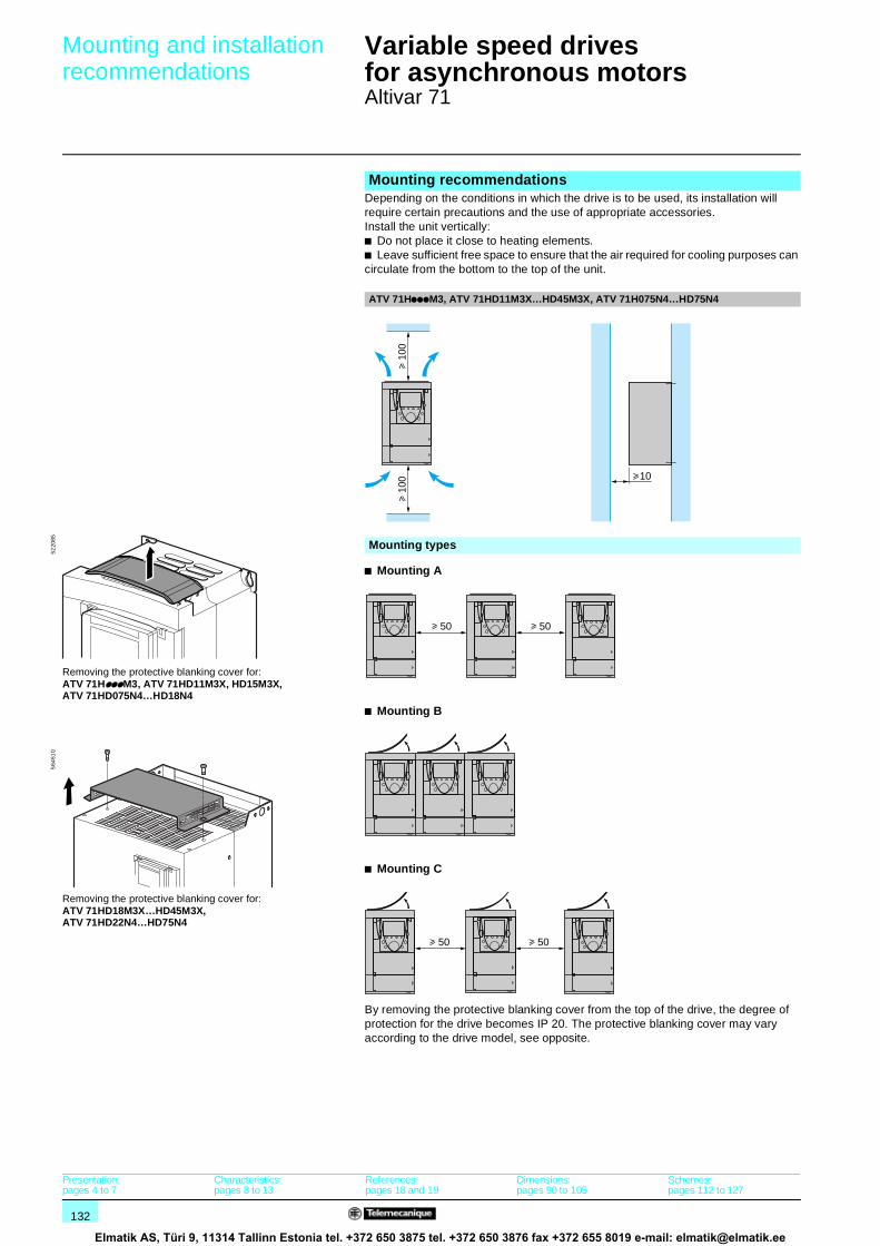
132
Mounting and installation recommendations 1
Variable speed drivesfor asynchronous motors 1
Altivar 71
b Mounting A
b Mounting B
b Mounting C
By removing the protective blanking cover from the top of the drive, the degree of protection for the drive becomes IP 20. The protective blanking cover may vary according to the drive model, see opposite.
Mounting recommendationsDepending on the conditions in which the drive is to be used, its installation will require certain precautions and the use of appropriate accessories.Install the unit vertically:b Do not place it close to heating elements.b Leave sufficient free space to ensure that the air required for cooling purposes can circulate from the bottom to the top of the unit.
ATV 71HpppM3, ATV 71HD11M3X…HD45M3X, ATV 71H075N4…HD75N4
u 10
0u
100 10
Mounting types
Removing the protective blanking cover for:ATV 71HpppM3, ATV 71HD11M3X, HD15M3X,ATV 71HD075N4…HD18N4
5220
85
Removing the protective blanking cover for:ATV 71HD18M3X…HD45M3X,ATV 71HD22N4…HD75N4
564
510
50 50
u 50 u 50
Presentation:pages 4 to 7
Characteristics:pages 8 to 13
References:pages 18 and 19
Dimensions:pages 90 to 105
Schemes:pages 112 to 127
Elmatik AS, Türi 9, 11314 Tallinn Estonia tel. +372 650 3875 tel. +372 650 3876 fax +372 655 8019 e-mail: [email protected]

133
Mounting and installation recommendations (continued)1
Variable speed drivesfor asynchronous motors 1
Altivar 71
Mounting recommendations (continued)Derating curves
The derating curves for the drive nominal current (In) depend on the temperature, the switching frequency and the mounting type.
ATV 71H037M3…HD15M3X and ATV 71H075N4…HD18N4
ATV 71HD22N4 and ATV 71HD30N4 (1)
ATV HD18M3X…HD45M3X and ATV 71HD37N4…HD75N4 (1)
For intermediate temperatures (55°C for example) interpolate between 2 curves.
(1) Above 50°C, ATV 71HD18M3X, HD22M3X, ATV 71HD30N4…HD75N4 drives should be fitted with a control card fan kit. See page 20.
In = 100
%
90
80
70
60
50
4 8 12 16 kHz
Switching frequency
60oC mountings A, B and C
50oC mounting A
40oC mounting A50oC mountings B and C
I/In
In = 100
%
90
80
70
60
50
4 8 12 16 kHzSwitching frequency
60oC mountings A, B and C
50oC mountings A, B and C
40oC mountings A, B and C
I/In
%
In = 100
90
80
70
60
50
4 8 12 16 kHz2,5Switching frequency
60oC mountings A, B and C
50oC mountings A, B and C
40oC mountings A, B and C
I/In
Presentation:pages 4 to 7
Characteristics:pages 8 to 13
References:pages 18 and 19
Dimensions:pages 90 to 105
Schemes:pages 112 to 127
Elmatik AS, Türi 9, 11314 Tallinn Estonia tel. +372 650 3875 tel. +372 650 3876 fax +372 655 8019 e-mail: [email protected]

134
Mounting and installation recommendations (continued)1
Variable speed drivesfor asynchronous motors 1
Altivar 71
Mounting recommendations (continued)ATV 71HD55M3X, HD75M3X, ATV 71HD90N4…HC50N4
ATV 71H hD55M3X, D90N4, C11N4 100
HC13N4, HC16N4 250HC20N4…HC28N4 300
HC31N4…HC40N4 450
HC50N4 550These drives can be mounted side by side, observing the following mounting recommendations:
h h
1040
040
0
1000
Presentation:pages 4 to 7
Characteristics:pages 8 to 13
References:pages 18 and 19
Dimensions:pages 90 to 105
Schemes:pages 112 to 127
Elmatik AS, Türi 9, 11314 Tallinn Estonia tel. +372 650 3875 tel. +372 650 3876 fax +372 655 8019 e-mail: [email protected]

135
Mounting and installation recommendations (continued)1
Variable speed drivesfor asynchronous motors 1
Altivar 71
Mounting recommendations (continued)Derating curves
The derating curves for the drive nominal current (In) depend on the temperature, the switching frequency and the mounting type.
For intermediate temperatures (55°C for example), interpolate between 2 curves.
ATV 71HD55M3X, HD75M3X ATV 71HD90N4
ATV 71HC11N4 ATV 71HC13N4
30
40
50 50 ˚C
60 ˚C
60
70
90
In = 100
120%
2 2,5 3 4 5 6 7 8 kHzSwitching frequency
50 ˚C
40 ˚C
60 ˚C
2 2,5
20
40
6067
0
80
In = 100
110
120%
3 4 5 6 7 8 kHzSwitching frequency
50 ˚C
40 ˚C
60 ˚C
2 2,5
20
40
60
70
0
80
In = 100
109
120%
3 4 5 6 7 8 kHzSwitching frequency
50 ˚C
40 ˚C
60 ˚C
2 2,5
20
40
60
78
0
In = 100107
120%
3 4 5 6 7 8 kHzSwitching frequency
Presentation:pages 4 to 7
Characteristics:pages 8 to 13
References:pages 18 and 19
Dimensions:pages 90 to 105
Schemes:pages 112 to 127
Elmatik AS, Türi 9, 11314 Tallinn Estonia tel. +372 650 3875 tel. +372 650 3876 fax +372 655 8019 e-mail: [email protected]

136
Mounting and installation recommendations (continued)1
Variable speed drivesfor asynchronous motors 1
Altivar 71
Mounting recommendations (continued)Derating curvesATV 71HC16N4 ATV 71HC20N4
ATV 71HC25N4 combined with a 220 kW motor ATV 71HC25N4 combined with a 250 kW motor
ATV 71HC28N4 ATV 71HC31N4
50 ˚C
40 ˚C
60 ˚C
2 2,5
20
40
60
71
80
0
In = 100
111120
%
3 4 5 6 7 8 kHzSwitching frequency
50 ˚C
40 ˚C
60 ˚C
2 2,5
20
40
60
72
80
0
In = 100
109
120%
3 4 5 6 7 8 kHzSwitching frequency
50 ˚C
40 ˚C
60 ˚C
2 2,5
20
40
60
72
80
0
In = 100
110
120%
3 4 5 6 7 8 kHzSwitching frequency
50 ˚C
40 ˚C
60 ˚C
2 2,5
20
40
60
7780
0
In = 100108
120%
3 4 5 6 7 8 kHzSwitching frequency
50 ˚C
40 ˚C
60 ˚C
2 2,5
20
40
60
81
0
In = 100107
120%
3 4 5 6 7 8 kHzSwitching frequency
50 ˚C
40 ˚C
60 ˚C
2 2,5
20
40
60
80
72
0
In = 100
110
120%
3 4 5 6 7 8 kHzSwitching frequency
Presentation:pages 4 to 7
Characteristics:pages 8 to 13
References:pages 18 and 19
Dimensions:pages 90 to 105
Schemes:pages 112 to 127
Elmatik AS, Türi 9, 11314 Tallinn Estonia tel. +372 650 3875 tel. +372 650 3876 fax +372 655 8019 e-mail: [email protected]

137
Mounting and installation recommendations (continued)1
Variable speed drivesfor asynchronous motors 1
Altivar 71
Mounting recommendations (continued)Derating curvesATV 71HC40N4 combined with a 355 kW motor ATV 71HC40N4 combined with a 400 kW motor
ATV 71HC50N4
50 ˚C
40 ˚C
60 ˚C
2 2,5
20
40
60
7680
0
In = 100
109
120
%
3 4 5 6 7 8 kHzSwitching frequency
50 ˚C
40 ˚C
60 ˚C
2 2,5
20
40
60
80
0
In = 100107
120
%
3 4 5 6 7 8 kHzSwitching frequency
50 ˚C
40 ˚C
60 ˚C
2 2,5
20
40
60
79
0
In = 100
108
120%
3 4 5 6 7 8 kHz
Switching frequency
Presentation:pages 4 to 7
Characteristics:pages 8 to 13
References:pages 18 and 19
Dimensions:pages 90 to 105
Schemes:pages 112 to 127
Elmatik AS, Türi 9, 11314 Tallinn Estonia tel. +372 650 3875 tel. +372 650 3876 fax +372 655 8019 e-mail: [email protected]
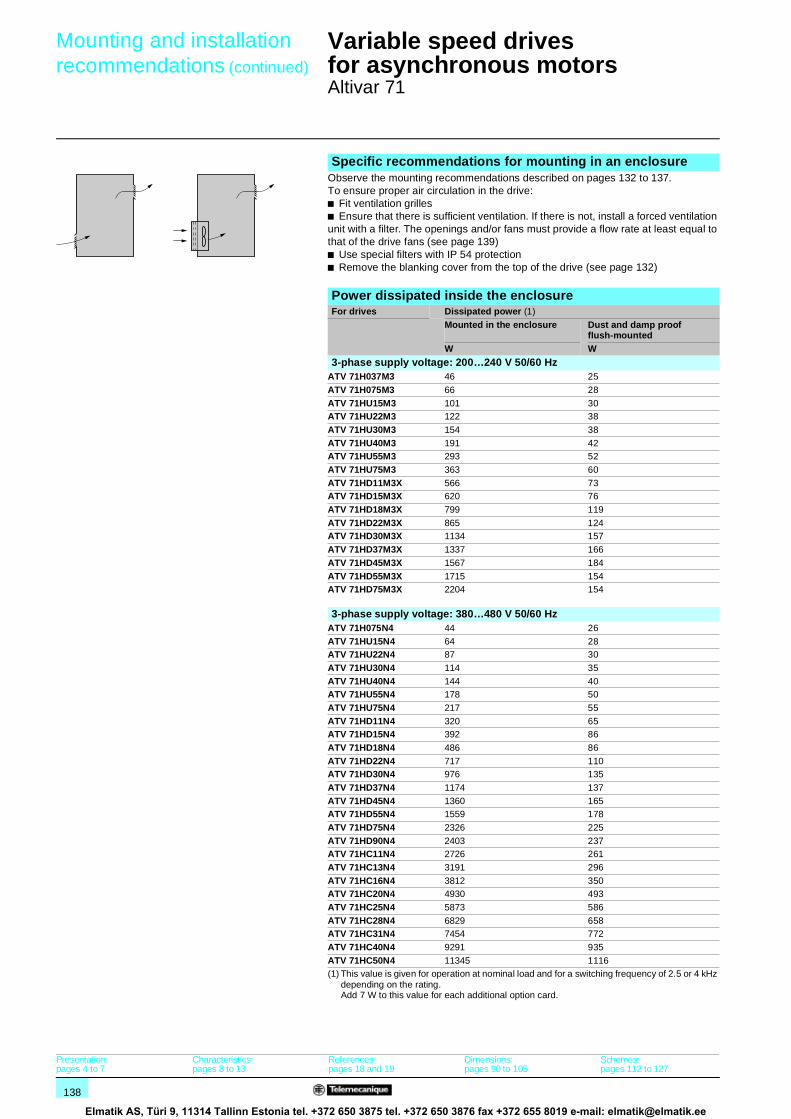
138
Mounting and installation recommendations (continued)1
Variable speed drivesfor asynchronous motors 1
Altivar 71
Specific recommendations for mounting in an enclosureObserve the mounting recommendations described on pages 132 to 137.To ensure proper air circulation in the drive:b Fit ventilation grillesb Ensure that there is sufficient ventilation. If there is not, install a forced ventilation unit with a filter. The openings and/or fans must provide a flow rate at least equal to that of the drive fans (see page 139)b Use special filters with IP 54 protectionb Remove the blanking cover from the top of the drive (see page 132)
Power dissipated inside the enclosureFor drives Dissipated power (1)
Mounted in the enclosure Dust and damp proof flush-mounted
W W
3-phase supply voltage: 200…240 V 50/60 HzATV 71H037M3 46 25
ATV 71H075M3 66 28
ATV 71HU15M3 101 30ATV 71HU22M3 122 38
ATV 71HU30M3 154 38
ATV 71HU40M3 191 42ATV 71HU55M3 293 52
ATV 71HU75M3 363 60
ATV 71HD11M3X 566 73ATV 71HD15M3X 620 76
ATV 71HD18M3X 799 119
ATV 71HD22M3X 865 124ATV 71HD30M3X 1134 157
ATV 71HD37M3X 1337 166
ATV 71HD45M3X 1567 184
ATV 71HD55M3X 1715 154ATV 71HD75M3X 2204 154
3-phase supply voltage: 380…480 V 50/60 HzATV 71H075N4 44 26
ATV 71HU15N4 64 28ATV 71HU22N4 87 30
ATV 71HU30N4 114 35
ATV 71HU40N4 144 40ATV 71HU55N4 178 50
ATV 71HU75N4 217 55
ATV 71HD11N4 320 65ATV 71HD15N4 392 86
ATV 71HD18N4 486 86
ATV 71HD22N4 717 110ATV 71HD30N4 976 135
ATV 71HD37N4 1174 137
ATV 71HD45N4 1360 165ATV 71HD55N4 1559 178
ATV 71HD75N4 2326 225
ATV 71HD90N4 2403 237ATV 71HC11N4 2726 261
ATV 71HC13N4 3191 296
ATV 71HC16N4 3812 350ATV 71HC20N4 4930 493
ATV 71HC25N4 5873 586
ATV 71HC28N4 6829 658ATV 71HC31N4 7454 772
ATV 71HC40N4 9291 935
ATV 71HC50N4 11345 1116(1) This value is given for operation at nominal load and for a switching frequency of 2.5 or 4 kHz
depending on the rating.Add 7 W to this value for each additional option card.
Presentation:pages 4 to 7
Characteristics:pages 8 to 13
References:pages 18 and 19
Dimensions:pages 90 to 105
Schemes:pages 112 to 127
Elmatik AS, Türi 9, 11314 Tallinn Estonia tel. +372 650 3875 tel. +372 650 3876 fax +372 655 8019 e-mail: [email protected]
139
Mounting and installation recommendations (continued)1
Variable speed drivesfor asynchronous motors 1
Altivar 71
Fan flow rate depending on the drive ratingFor drive Flow rate m3/hour
ATV 71H037M3…HU15M3,ATV 71H075N4…HU22N4
17
ATV 71HU22M3…HU40M3,ATV 71HU30N4, HU40N4
56
ATV 71HU55M3, ATV 71HU55N4, HU75N4
112
ATV 71HU75M3, ATV 71HD11N4
163
ATV 71HD11M3X, HD15M3XATV 71HD15N4, HD18N4
252
ATV 71HD18M3X, HD22M3X,ATV 71HD22N4
203
ATV 71HD30N4, HD37N4 203
ATV 71HD30M3X…HD45M3X 406
ATV 71HD45N4…HD75N4 406
ATV 71HD55M3X, ATV 71HD90N4
402
ATV 71HD75M3X, ATV 71HC11N4
774
ATV 71HC13N4 745
ATV 71HC16N4 860
ATV 71HC20N4… HC28N4 1260
ATV 71HC31N4, HC40N4 2100
ATV 71HC50N4 2400
Sealed metal enclosure (IP 54 degree of protection)The drive must be mounted in a dust and damp proof casing in certain environmental conditions: dust, corrosive gases, high humidity with risk of condensation and dripping water, splashing liquid, etc.This enables the drive to be used in an enclosure where the maximum internal temperature reaches 50°C.
Calculating the enclosure dimensionsMaximum thermal resistance Rth (°C/W)
θ = maximum temperature inside enclosure in °Cθe = maximum external temperature in °CP = total power dissipated in the enclosure in W
Power dissipated by drive: see page 138 (mounting in an enclosure or flush-mounting in an enclosure).Add the power dissipated by the other equipment components.
Useful heat dissipation surface of enclosure S (m2)(sides + top + front panel if wall-mounted)
K = enclosure thermal resistance per m2
For a metal enclosure:b K = 0.12 with internal fanb K = 0.15 without fanNote: Do not use insulated enclosures, as they have a poor level of conductivity.
Rth θ θeP
----------------=
SK
Rth----------=
Presentation:pages 4 to 7
Characteristics:pages 8 to 13
References:pages 18 and 19
Dimensions:pages 90 to 105
Schemes:pages 112 to 127
Elmatik AS, Türi 9, 11314 Tallinn Estonia tel. +372 650 3875 tel. +372 650 3876 fax +372 655 8019 e-mail: [email protected]

140
Combinations 1 Variable speed drivesfor asynchronous motors 1
Altivar 71
b Frequent or necessary use
Compatible combinations of functions and applicationsApplications Hoisting Lift Material handling
Machines Cranes, overhead cranes, gantries (vertical hoisting, translation, slewing), lifting platforms
Retrofit lifts up to 1.2 ms Palletizers/depalletizers, carton packers, labelling machines, conveyors, roller tables
Motor control functionsFlux vector control with and without sensor b b b2-point vector control bOpen-loop synchronous motor
ENA system
Voltage/frequency ratio bOutput frequency 1000 Hz
Motor overvoltage limiting b b bApplication functionsDifferential bipolar reference b bReference delinearization (magnifying glass effect) b bFrequency control input
Operations on the references (summing, subtraction, multiplication)
b
Brake control b b bBrake feedback via contact bHigh-speed hoisting bLoad measurement b bLoad sharing b bLimit switch management b b bS ramp b b bCurrent limiting
Output contactor command bIntegrity check of output contactor bRescue following power failure bStop on thermal alarm bTorque control bTorque limit bMotor fluxing b bParameter set switching b b bMotor switching b bPosition control via limit switches bUncontrolled output cut bDetection of current or torque limit bPID regulator
Auto/man
Reference storage
+/- speed, single action button
+/- speed, double action button b+/- speed around a reference
Traverse control
Automatic catching a spinning load with speed detection(catch a spinning load)
Undervoltage management
Fastest possible stop
Presentation:pages 4 to 7
Characteristics:pages 8 to 13
References:pages 18 and 19
Dimensions:pages 90 to 105
Schemes:pages 112 to 127
Elmatik AS, Türi 9, 11314 Tallinn Estonia tel. +372 650 3875 tel. +372 650 3876 fax +372 655 8019 e-mail: [email protected]

141
11
(For other functions that can be used for all applications, see pages 152 to 173)Packing Textiles Wood High inertia Process
Palletizers/depalletizers, carton packers, labelling machines
Weaving looms, carding frames, washing machines, spinners, drawing frames
Automatic lathes, saws, milling
Centrifuges, mixers, unbalanced machines (beam pumps, presses)
Sectional production lines(speed < 500 m/min)Example: building materials
b b b b bbb
bb b
b bb b b b b
b
b bb b b
b b b
b bb b b
bb b b b bbb
bb
b bb b
b bbb b b
b b b bb b
Presentation:pages 4 to 7
Characteristics:pages 8 to 13
References:pages 18 and 19
Dimensions:pages 90 to 105
Schemes:pages 112 to 127
Elmatik AS, Türi 9, 11314 Tallinn Estonia tel. +372 650 3875 tel. +372 650 3876 fax +372 655 8019 e-mail: [email protected]
142
Functions 1 Variable speed drivesfor asynchronous motors 1
Altivar 71
Summary of functionsRemote graphic display terminal functions
Description page 144
Navigation page 145Password page 145
Integrated 7-segment display terminalPresentation page 146
Start-upSimply Start menu page 146
Programming using macro-configurations page 147MONITORING menu page 148
Configuration and settingsPresentation page 148
OperationPresentation page 148
Maintenance, diagnosticsResponse to faults or alarms page 149
Fault log and help page 149IDENTIFICATION menu page 149
Test functions page 149
Oscilloscope function page 149
Controlling the driveVia the drive I/O page 150
Via the remote graphic display terminal page 150
Via a communication network page 151
Application functions2-wire control
- State detection page 152
- Transition detection page 152
- Forward operation as priority page 1523-wire control page 152
Phase rotation page 152
Ramps- Time page 152
- Profile (linear, S, U) page 153
- Switching page 153- Automatic adaptation page 153
Preset speeds page 154
Jog operation page 154Limiting low speed operating time page 154
Motor control type
- Flux vector control with sensor page 155- Sensorless flux vector control page 155
- 2-point vector control page 155
- Voltage/frequency ratio page 155- ENA system page 155
- Synchronous motor page 155
Using an incremental encoder page 156Encoder tests page 156
Limiting motor overvoltage page 156
Auto-tuning page 156Switching frequency, noise reduction page 156
Motor fluxing page 157
Brake control- Movement type page 157
- Brake feedback via contact page 157
- Brake release pulse page 157- Brake engage on reversal of operating direction page 157
- Brake engage request time delay page 157
- Automatic DC injection page 157
Presentation:pages 4 to 7
Characteristics:pages 8 to 13
References:pages 18 and 19
Dimensions:pages 90 to 111
Schemes:pages 112 to 127
Elmatik AS, Türi 9, 11314 Tallinn Estonia tel. +372 650 3875 tel. +372 650 3876 fax +372 655 8019 e-mail: [email protected]

143
Functions 1 Variable speed drivesfor asynchronous motors 1
Altivar 71
Summary of functions (continued)Application functions (continued)
Limit switch management page 157
High-speed hoisting page 158External weight measurement page 159
Load sharing page 159
Output contactor- Control page 159
- Integrity check page 159
Stop on thermal alarm page 159Evacuation following power failure page 159
Uncontrolled output cut page 160
+/- speed- Single action buttons page 160
- Double action buttons page 160
- Reference saving page 161- Around a reference page 161
Spooling
- Traverse control page 161- Counter wobble page 162
Automatic catching of a spinning load with speed detection page 162
Undervoltage management page 163Braking balance page 163
Braking resistor thermal protection page 163
Parameter set switching page 163Motor or configuration switching page 163
Position control via limit switches page 164
Short and long cam operation page 164
Reference switching page 165Operations on the references
- Summing inputs page 165
- Subtraction inputs page 165- Multiplication inputs page 165
PID regulator
- Preset PID references page 166- Predictive speed reference page 166
- Auto/man page 166
Torque control page 167Torque limit page 168
Torque or current limit detection page 168
Current limit page 168Reference saving page 169
Stop types
- Freewheel stop page 169- Fast stop page 169
- Fastest possible stop page 169
- DC injection stop page 169Motor thermal protection page 170
Drive thermal protection page 170
IGBT thermal protection page 170Configuring the drive’s fault response page 171
Resetting resettable faults page 171
General reset (disables all faults) page 171Automatic restart page 172
PTC probe protection page 172
IGBT testing page 172Resetting operating time to zero page 172
External fault page 172
Line contactor control page 173Forced local mode page 173
Presentation:pages 4 to 7
Characteristics:pages 8 to 13
References:pages 18 and 19
Dimensions:pages 90 to 111
Schemes:pages 112 to 127
Elmatik AS, Türi 9, 11314 Tallinn Estonia tel. +372 650 3875 tel. +372 650 3876 fax +372 655 8019 e-mail: [email protected]

144
Functions (continued) 1 Variable speed drivesfor asynchronous motors 1
Altivar 71
Remote graphic display terminal functions This display terminal is attached to the front of the drive. It includes the integrated 7-segment display terminal for drives supplied without a graphic display terminal.
b Descriptionv Description of graphic display terminal1 Graphic display unit:
- 8 lines, 240 x 160 pixels- large digit display that can be read from 5 m away- bar chart display
2 Assignable functions keys F1, F2, F3, F4:- dialogue functions: direct access, help screens, navigation- application functions: Local/Remote, preset speed.
3 STOP/RESET key: local control of motor stopping/fault clearing4 RUN key: local control of motor operation5 Navigation button:
- Press to save the current value (ENT)- Turn ± to increase or decrease the value, go to the next or previous line
6 FWD/REV key: reverses the direction of rotation of the motor7 ESC key: aborts a value, parameter or menu to return to the previous option.
Note: Keys 3, 4 and 6 can be used to control the drive directly.
v Description of graphic display unit 1 Display line. Its content can be configured; the factory settings show:
- the drive status (e.g. RUN)- the active control channel (e.g. “Term”: terminals)- the frequency reference- the current in the motor
2 Menu line. Indicates the current menu or submenu.3 Area displaying menus, submenus, parameters, values, bar charts, in the form of
a scrolling window, with a maximum of 5 lines.The line or value selected using the navigation button is displayed in reverse video (see opposite).
4 Section displaying the functions assigned to the keys F1 to F4 and aligned with them, for example:- >> : Horizontal scrolling to the right, or proceeding to the next menu or submenu,
or, in the case of a value, decreasing the value, displayed in reverse video (see example opposite)
- << : Horizontal scrolling to the left, or proceeding to the next menu or submenu, or, in the case of a value, increasing the value, displayed in reverse video
- Quick: Rapid access to a parameter from any screen when the Quick function is displayed above the F4 key
- HELP: Contextual help- Code: Displays the selected parameter code- Other functions (application functions) can be assigned to these keys via the 1.6
COMMAND menu.5 : Means that this display window does not scroll further down.
: Means that this display window can scroll further down.6 : Means that this display window can scroll further up.
: Means that this display window does not scroll further up.
5221
48
1
2
3
4
7
6
5
+50.00HzTerm1. DRIVE MENU
1.3 SETTINGS
5.4A
1.1 SIMPLY START
1.4 MOTOR CONTROL
1.5 INPUTS / OUTPUTS CFG
<< >> Quick
RUN
F1 F2 F3 F4
5
3
4
2
1
1.2 MONITORING
6
Code
5221
49
Presentation:pages 4 to 7
Characteristics:pages 8 to 13
References:pages 18 and 19
Dimensions:pages 90 to 111
Schemes:pages 112 to 127
Elmatik AS, Türi 9, 11314 Tallinn Estonia tel. +372 650 3875 tel. +372 650 3876 fax +372 655 8019 e-mail: [email protected]

145
Functions (continued) 1 Variable speed drivesfor asynchronous motors 1
Altivar 71
b PasswordAltivar 71 drives allow individual parameters to be selected for password protection. Rights can be set for save operations and for loading the configuration.
Remote graphic display terminal functions (continued)b Navigation: accessing menus and parametersStructure of main menus:
1 Drive menu:Menu type Function
1.1 SIMPLY START Simplified menu for a quick start-up1.2 MONITORING Displays current values for motor, inputs/outputs
and communication (command words, status words, etc.)
1.3 SETTINGS Accesses the adjustment parameters, which can be modified during operation
1.4 MOTOR CONTROL Accesses the motor parameters, including adjustment of motor control profiles
1.5 INPUTS/OUTPUTS CFG Configures the I/O and transforms signals1.6 COMMAND Configures the command and reference channels1.7 APPLICATION FUNCT. Configures the application functions (preset
speeds, PID regulator, etc.)1.8 FAULT MANAGEMENT Configures the fault management process1.9 COMMUNICATION Configures the communication networks1.10 DIAGNOSTICS Provides diagnostics for motor and drive,
integrated test procedures, fault log1.11 IDENTIFICATION Identifies the drive and the internal options1.12 FACTORY SETTINGS Restores factory settings (completely or by
parameter group)1.13 USER MENU Accesses the parameters selected by the user1.14 PROGRAMMABLE CARD Accesses the parameters for the Controller Inside
programmable card
2 Display line
3 Display screen: Displays values in the form of bar charts or digital values, depending on the extent of customization.
4 Main menu:Menu type Function
1. DRIVE MENU See above (1 Drive menu) 2. ACCESS LEVEL 4 access levels: basic, limited, advanced, expert3. OPEN/SAVE AS Transfers files between the graphic display
terminal and the drive4. PASSWORD Provides password protection for the
configuration5. LANGUAGE Choice of 6 languages available (English,
German, Spanish, French, Italian and Chinese)6. MONITORING CONFIG. Customizes the display line 2 and the display
screen 3 (bar charts, digital values)7. DISPLAY CONFIG. Configures how parameters are displayed:
customization, selection for User menu, visibility, accessibility
2.2kW/3HP
Config n˚1
380/480V
ATV71HU22N4
+50.00HzTerm1. DRIVE MENU
1.3 SETTINGS
5.4A
1.2 MONITORING
1.4 MOTOR CONTROL
1.5 INPUTS / OUTPUTS CFG
<< >> QuickCode
RUN
+43.33HzTerm 5.4ARUN
+0.00HzTerm 0ARUN
1.1 SYMPLY START
1
MAIN MENU
3. OPEN / SAVE AS
2. LEVEL ACCESS
4. PASSWORD
5. LANGUAGE
Quick
1. DRIVE MENU
4
Motor speed
Quick
2
3
Min=0 Max=1500
1300 rpm
<< >>
5221
50
Presentation:pages 4 to 7
Characteristics:pages 8 to 13
References:pages 18 and 19
Dimensions:pages 90 to 111
Schemes:pages 112 to 127
Elmatik AS, Türi 9, 11314 Tallinn Estonia tel. +372 650 3875 tel. +372 650 3876 fax +372 655 8019 e-mail: [email protected]

146
Functions (continued) 1 Variable speed drivesfor asynchronous motors 1
Altivar 71
Integrated 7-segment display terminalATV 71pppppM3, ATV 71HD11M3X, HD15M3X and ATV 71H075N4…HD15N4 drives can be supplied without a graphic display terminal. In this case, they are equipped with an integrated 7-segment display terminal. This can be used to:v Display status and faultsv Access and modify parameters
Start-upThe Altivar 71 drive is supplied ready for use for most applications.When the drive is switched on, the menus for setting the language and access level appear automatically.
b Simply start menuBy accessing the Simply start menu directly it is possible to: v Pre-program the drive for an application:
- Select the relevant macro-configuration- 2-wire/3-wire control
v Benefit from optimum motor performance:- Enter data from the motor rating plate- Auto-tuning.
v Protect the motor by setting the drive’s integrated electronic thermal overload relay
M. handling
50Hz IEC
2.2kW
400V
:
:
:
:
: 2 wire
+50.00HzTerm1.1 SIMPLY START
Standard mot. Freq.
5.4A
Macro-configuration
Rated motor power
Rated motor volt.
<< >> QuickCode
RUN
2/3 wire control
Simply start menu
522
151
Presentation:pages 4 to 7
Characteristics:pages 8 to 13
References:pages 18 and 19
Dimensions:pages 90 to 111
Schemes:pages 112 to 127
Elmatik AS, Türi 9, 11314 Tallinn Estonia tel. +372 650 3875 tel. +372 650 3876 fax +372 655 8019 e-mail: [email protected]

147
Functions (continued) 1 Variable speed drivesfor asynchronous motors 1
Altivar 71
Start-up (continued)b Programming using macro-configurationsProgramming using macro-configurations offers the choice of seven options corresponding to the various business areas and applications:v Start/stopv Material handlingv General usev Hoistingv PID regulationv Communication network connectivityv Master/slave applicationsChoosing one of these macro-configurations automatically assigns the functions, parameters and I/O, even in the case of option cards. Although the configuration is preset, it can still be modified, if necessary.
The Start/stop macro-configuration is set as the factory configuration.The preset functions for each macro-configuration are given in the table below.
Type of macro-configuration
Start/stop Material handling
General use Hoisting PID regulation Communication network connectivity
Master/slave application
Altivar 71 drive I/OAI1 Ref. 1 channel Ref. 1 channel Ref. 1 channel Ref. 1 channel PID reference Ref. 2 channel
Ref. 1 channelby bus
Ref. 1 channel
AI2 Not assigned Sum ref. 2 Sum ref. 2 Not assigned PID feedback Not assigned Torque ref.2 channel
AO1 Motor freq. Motor freq. Motor freq. Motor freq. Motor freq. Motor freq. Signed torque2-wire LI1 Forward Forward Forward Forward Forward Forward Forward
LI2 Reverse Reverse Reverse Reverse Reverse Reverse Reverse
LI3 Not assigned 2 preset speeds JOG Fault reset PID integralreset
Ref 2switch
Trq/spdswitching
LI4 Not assigned 4 preset speeds Fault reset Ext fault PID 2preset ref.
Fault reset Fault reset
LI5 Not assigned 8 preset speeds Torque limit Not assigned PID 4preset ref.
Not assigned Not assigned
LI6 Not assigned Fault reset Not assigned Not assigned Not assigned Not assigned Not assigned3-wire LI1 Stop Stop Stop Stop Stop Stop Stop
LI2 Forward Forward Forward Forward Forward Forward Forward
LI3 Reverse Reverse Reverse Reverse Reverse Reverse ReverseLI4 Not assigned 2 preset speeds JOG Fault reset PID integral
resetRef 2switch
Trq/spdswitching
LI5 Not assigned 4 preset speeds Fault reset Ext fault PID 2preset ref.
Fault reset Fault reset
LI6 Not assigned 8 preset speeds Torque limit Not assigned PID 4preset ref.
Not assigned Not assigned
R1 Faulty Faulty Faulty Faulty Faulty Faulty Faulty
R2 Not assigned Not assigned Not assigned Brk control Not assigned Not assigned Not assigned
I/O extension card I/O2-wire LI7 Not assigned Not assigned Not assigned Not assigned Not assigned Not assigned Not assigned
3-wire LI7 Not assigned Not assigned Not assigned Not assigned Not assigned Not assigned Not assignedLI8 to LI14 Not assigned Not assigned Not assigned Not assigned Not assigned Not assigned Not assigned
LO1 to LO4 Not assigned Not assigned Not assigned Not assigned Not assigned Not assigned Not assigned
R3/R4 Not assigned Not assigned Not assigned Not assigned Not assigned Not assigned Not assignedAI3, AI4 Not assigned Not assigned Not assigned Not assigned Not assigned Not assigned Not assigned
RP Not assigned Not assigned Not assigned Not assigned Not assigned Not assigned Not assigned
AO2 Motor current Motor current Motor current Motor current Motor current Motor current Motor currentAO3 Not assigned Signed torque Not assigned Signed torque PID error Not assigned Motor freq.
Graphic display terminal keysF1 key Not assigned Not assigned Not assigned Not assigned Not assigned Control
via graphic display terminal
Not assigned
F2, F3, F4 keys Not assigned Not assigned Not assigned Not assigned Not assigned Not assigned Not assigned
Presentation:pages 4 to 7
Characteristics:pages 8 to 13
References:pages 18 and 19
Dimensions:pages 90 to 111
Schemes:pages 112 to 127
Elmatik AS, Türi 9, 11314 Tallinn Estonia tel. +372 650 3875 tel. +372 650 3876 fax +372 655 8019 e-mail: [email protected]

148
Functions (continued) 1 Variable speed drivesfor asynchronous motors 1
Altivar 71
Start-up (continued)
b MONITORING menuThe MONITORING menu can be used to display commands, the operation of the motor and application through the drive of its I/O or of the communication network connections.
Logic input map
Communication map
10
PR
10
LI7 LI8 LI9 LI10 LI11 LI12 LI13 LI14
LI1 LI2 LI3 LI4 LI5 LI6
+50.00HzTermLogic input map
80A
<< >> Quick
RUN
5.4 A
1300 rpm
80 %
85 %
:
:
:
:
: 43.3 Hz
+43.33HzTerm1.2 MONITORING
Motor speed
5.4A
Motor current
Motor thermal state
Drv thermal state
<< >> QuickCode
RUN
Frequency Ref.
Displaying physical values
522
169
ABCD Hex
CANopen
+50.00 Hz
2153 Hex
:
:
:
:
: Modbus
+50.00HzMod.COMMUNICATION MAP
Active ref. channel
5.4A
Cmd Value
Frenquency ref.
ETA status word
<< >> QuickCode
RUN
Cmd channel
Configuration and settings
The SETTINGS menu can be used to configure all the drive’s settings.Activating a function automatically provides access to the related settings on the same screen (the application functions are described on pages 152 to 173).
Setting a function
Configuring a value
LI4
LI3
LI5
NO
10.0 Hz
:
:
:
:
:
+0.00HzTermPRESET SPEEDS
8 preset speeds
0.0A
4 preset speeds
16 preset speeds
Preset speed 2
<< >> QuickCode
RDY
2 preset speeds
3,00 s
0,01
3,00 s
5,00 s
5,00 s
:
:
:
:
:
+50.00HzTerm1.3 SETTINGS
Deceleration
1250A
Acceleration
Acceleration 2
Deceleration 2
<< >> QuickCode
RUN
Ramp increment
Settings screen
5221
54
Min=0,01 Max=9999
9. 1 s5
+0.00HzTermACCELERATION
0A
<< >> Quick
RDY
Operation
The display screen appears automatically every time the drive is turned on.There are different possible scenarios:b One or two bar charts are displayed.b One, two or five digital values are displayed.
+43.33HzTerm 5.4ARUNMotor speed
QuickMin=0 Max=1500
1300 rpm
5335
25
1 bar chart
+45.1
+38.0HzTermOutput frequency
10A
<< >> Quick
DEC
Hz
1 digital value
5.4 A
1300 rpm
80 %
85 %
:
:
:
:
: 43.3 Hz
+43.33HzTerm1.2 MONITORING
Motor speed
5.4A
Motor current
Motor thermal state
Drv thermal state
<< >> QuickCode
RUN
Frequency Ref.
5 digital values
Presentation:pages 4 to 7
Characteristics:pages 8 to 13
References:pages 18 and 19
Dimensions:pages 90 to 111
Schemes:pages 112 to 127
Elmatik AS, Türi 9, 11314 Tallinn Estonia tel. +372 650 3875 tel. +372 650 3876 fax +372 655 8019 e-mail: [email protected]

149
Functions (continued) 1 Variable speed drivesfor asynchronous motors 1
Altivar 71
b Oscilloscope functionThe Altivar 71 drive has an oscilloscope function, which produces traces that can be viewed using the PowerSuite software workshop. The PowerSuite software workshop can also be used to carry out remote diagnostics via modem.
Maintenance, diagnosticsNew functions have been added to the Altivar 71 drive to enable it to provide quick and simple maintenance, ultimately boosting productivity:
b Response to faults or alarmsIt is possible to use the alarm management or drive operation configuration functions to take corrective measures before stopping the machine.
b Fault log and helpWhen a fault occurs, a help screen is available to quickly identify the cause of the fault.As soon as the fault occurs, values such as speed, current, thermal state, timer are saved and restored in the fault log.The last 8 faults are stored.
b IDENTIFICATION menuThe IDENTIFICATION menu can be used to display the relevant serial numbers and software versions, thereby helping to manage the equipment base. This information, also available from the PowerSuite software workshop, can be exported to other database-type software applications.
b Test functionsThe Altivar 71 drive includes the following test functions:v Identifying any motor short-circuit before start-upv Running, via the graphic display terminal or PowerSuite software workshop, automatic procedures during maintenance operations aimed at testing:
- the motor- the drive power components
The test results are shown on the graphic display terminal or using the PowerSuite software workshop.It is also possible to write and read messages in the drive using the graphic display terminal or the PowerSuite software workshop.
+50.00HzTermFAULT HISTORY
External FLT
0.0A
Overcurrent
Overvoltage
Undervoltage
QuickHelp
SCF1
Short circuit
533
523.
Fault log
+50.00HzTermMOTOR SHORT CIRCUIT
0.0A
Perform the diagnostic test.
Quick
SCF1
Check the connection cables
and the motor insulation.
Troubleshooting screen
5221
62
+50.00HzTerm1.11 IDENTIFICATION
380 / 480 V
5.4A
2.2 kW / 3HP
Appl. Software V1.0 IE 01
MC Software V1.0 IE 01
<< >> Quick
RUN
ATV71HU22N4
Identification screen
522
163
+50.00HzTermSERVICE MESSAGE
5.4A
Quick
RUN
For technical support,
dial 32 12 75
Example of a customized message
522
157
Presentation:pages 4 to 7
Characteristics:pages 8 to 13
References:pages 18 and 19
Dimensions:pages 90 to 111
Schemes:pages 112 to 127
Elmatik AS, Türi 9, 11314 Tallinn Estonia tel. +372 650 3875 tel. +372 650 3876 fax +372 655 8019 e-mail: [email protected]

150
Functions (continued) 1 Variable speed drivesfor asynchronous motors 1
Altivar 71
Controlling the driveb Via the drive I/OControl signals are transmitted via cable to the I/O. Functions are assigned to logic inputs, analog inputs, etc.A logic input can be assigned to more than one function. This means that two functions can be controlled using a single signal, thereby limiting the number of inputs required.
The Altivar 71 drive I/O can be configured independently from each other. For instance,v A time delay can be applied when it comes to reading the logic inputs, so as to avoid any bounce-back from certain switches.v Transforming incoming signals on the analog inputs can help the drive fully adapt to the control devices and applications:
- minimum and maximum values for the input signal- input filtering in order to eliminate unwanted interference from the signals
received- magnifying glass effect through delinearizing the input signal in order to increase
the precision with small amplitude signals- Pedestal and Deadband functions for signals in order to prevent low speed
operations which can have an adverse effect on the application- Mid-point function, which can be used from a unipolar input signal to obtain a
bipolar output signal to control the speed and direction of rotationv Transforming analog outputs which transfer information sent by the drive to other devices (display units, drives, PLCs, etc.):
- voltage or current output signal- minimum and maximum values for the output signal- output signal filtering
Logic outputs can be delayed on activation and deactivation. The output state can also be configured when the signal is active.The frequency control signals are also transformed by the drive:v signal frequency minimum and maximum values (30 kHz on the extended I/O card’s RP input, 300 kHz maximum on the encoder interface card input).
b Via the remote graphic display terminalThe rotation commands and references (torque, speed or PID) can be controlled via the graphic display terminal. Some application functions can also be assigned to the function keys F1, F2, F3 and F4 on the graphic display terminal. It is possible to manage a change in command and/or reference source (bumpless function) in different ways.For example, two options are offered when switching control from via the terminals to via the graphic display terminal:v stop the Altivar 71 drive, orv continue operation with a copy of the direction of rotation and reference
Presentation:pages 4 to 7
Characteristics:pages 8 to 13
References:pages 18 and 19
Dimensions:pages 90 to 111
Schemes:pages 112 to 127
Elmatik AS, Türi 9, 11314 Tallinn Estonia tel. +372 650 3875 tel. +372 650 3876 fax +372 655 8019 e-mail: [email protected]

151
Functions (continued) 1 Variable speed drivesfor asynchronous motors 1
Altivar 71
Controlling the drive (continued)b Via a communication networkv I/O profileThe I/O profile, which is easy and quick to use, can be used to control the Altivar 71 drive via the communication network, in the same way as via the I/O terminals.When commands are sent via a network they are written in a command word. This word behaves like virtual terminals containing logic inputs.Application functions can be assigned to the bits of this word. More than one function can be assigned to the same bit.
The commands and references can come from different sources, such as the terminals, graphic display terminal or communication networks.Each source can be set or switched individually using logic inputs or command word bits.
The I/O profile is supported by all integrated communication ports (Modbus, CANopen), as well as by all the communication cards available (Ethernet TCP/IP, Fipio, Profibus DP, etc.).
v CiA DSP 402 profile (CANopen Device Profile Drives and Motion Control)This profile from the organization CiA (CAN in Automation) describes standard functions, parameters and operation for variable speed drives.This standard is an extension of the DRIVECOM profile. The Altivar 71 drive complies with the CiA DSP 402 standard and it supports the following 2 modes in this profile: separate and not separate.
Separate modeThe Start/Stop commands and references can come for different sources.For example, the speed reference is transmitted by the Ethernet TCP/IP network and the Start/Stop commands by the logic signals wired on the terminals.
Each source can be set or switched individually using logic inputs or command word bits.
Not separate modeThe Start/Stop commands and references (speed, torque, PID, etc.) come from the same source (e.g. CANopen bus).
It is possible to replace this source by another one, using a logic input or command word bit.
The CiA DSP 402 profile is supported by all integrated communication ports (Modbus, CANopen), as well as by all the communication cards available (Ethernet TCP/IP, Fipio, Profibus DP, etc.).
v ODVA profileThe ODVA profile is supported by the DeviceNet communication card.
Presentation:pages 4 to 7
Characteristics:pages 8 to 13
References:pages 18 and 19
Dimensions:pages 90 to 111
Schemes:pages 112 to 127
Elmatik AS, Türi 9, 11314 Tallinn Estonia tel. +372 650 3875 tel. +372 650 3876 fax +372 655 8019 e-mail: [email protected]

152
Functions (continued) 1 Variable speed drivesfor asynchronous motors 1
Altivar 71
b 2-wire controlThis can be used to control the direction of operation by means of a stay-put contact.It is enabled by means of 1 or 2 logic inputs (non-reversing or reversing).
This function is suitable for all non-reversing and reversing applications.3 operating modes are possible:v detection of the state of the logic inputsv detection of a change in state of the logic inputsv detection of the state of the logic inputs with forward operation always having priority over reverse
b 3-wire control This can be used to control the operating and stopping direction by means of pulsed contacts. It is enabled by means of 2 or 3 logic inputs (non-reversing or reversing).
This function is suitable for all non-reversing and reversing applications.
b Phase rotationThis function can be used to reverse the direction of rotation without modifying the drive wiring.
b Rampsv Acceleration and deceleration ramp times This can be used to define acceleration and deceleration ramp times according to the application and the machine dynamics.
Application functions
Linear acceleration ramp Linear deceleration rampFrS: Nominal motor frequencyt1: Acceleration timet2: Deceleration timet1 and t2 can be set independently from 0.01 to 9999 s (according to one of the following ramp increments: 0.01 s, 0.1 s or 1 s) Factory setting: 3 s.
24 V LI1 LIx
Altivar 71 control terminals LI1: forwardLIx: reverse
Wiring diagram for 2-wire control
1
1
1
0
0
0
0
f (Hz)
Stop
Forward
Reverse
t
t
t
t
Example of 3-wire control operation
24 V LI1 LI2 LIx
Altivar 71 control terminals LI1: StopLI2: ForwardLIx: Reverse
Wiring diagram for 3-wire control
0.01
Linear
3.92 s
0.54 s
0.0 Hz
:
::
:
:
+0.00HzTermRAMP
Acceleration
0.0A
Ramp increment
Deceleration
Ramp 2 threshold
QuickCode
RDY
Ramp shape
Ramp settings
5221
64
FrS
f (Hz)
0t1
t
FrS
f (Hz)
0t2
t
Presentation:pages 4 to 7
Characteristics:pages 8 to 13
References:pages 18 and 19
Dimensions:pages 90 to 111
Schemes:pages 112 to 127
Elmatik AS, Türi 9, 11314 Tallinn Estonia tel. +372 650 3875 tel. +372 650 3876 fax +372 655 8019 e-mail: [email protected]

153
Functions (continued) 1 Variable speed drivesfor asynchronous motors 1
Altivar 71
v Acceleration and deceleration ramp profileThis can be used to gradually increase the output frequency starting from a speed reference, following a linear profile or a preset profile.
In the case of applications involving handling, packaging and passenger transport, the use of S ramps takes up mechanical play and eliminates jolts and also limits “non-following” of speed during rapid transient operation of high-inertia machines. Selecting “linear”, “S”, “U” or customized profiles assigns both the acceleration and deceleration ramps.
v Ramp switching This can be used to switch 2 acceleration and deceleration ramp times, which can be adjusted separately. Ramp switching can be enabled by:
- a logic input- a frequency threshold- a combination of the logic input (or a command word bit) and the frequency
threshold- a command word bit
Function suitable for:- material handling with smooth starting and approach- machines with fast steady state speed correction
v Automatic adaptation of deceleration rampThis can be used to automatically adapt the deceleration ramp if the initial setting is too low when the load inertia is taken into account. This function prevents the drive from locking in the event of an overbraking fault.When this function is active and a short deceleration time has been set, the drive optimizes the motor power supply in order to achieve a high braking torque.
Function suitable for all applications which do not need to stop at a precise moment and do not use braking resistors.
Automatic adaption must be disabled for machines with a stop position on a ramp and using a braking resistor. This function is automatically disabled if the brake sequence is configured.
S ramps U ramps Customized ramps
FrS: Nominal motor frequencyt1: Ramp time sett2 = 0.6 x t1The curve coefficient is fixed.
FrS: Nominal motor frequencyt1: Ramp time sett2 = 0.5 x t1The curve coefficient is fixed.
FrS: Nominal motor frequencytA1: Can be set between 0 and 100% (of ACC or AC2)tA2: Can be set between 0 and (100% - tA1) (of ACC or AC2)tA3: Can be set between 0 and 100% (of dEC or dE2)tA4: Can be set between 0 and (100% - tA3) (of dEC or dE2)ACC: Acceleration ramp 1 timeAC2: Acceleration ramp 2 timedEC: Deceleration ramp 1 timedE2: Deceleration ramp 2 time
f (Hz) f (Hz)
FrS FrS
0 0t tt2
t1
t2
t1
f (Hz)
FrS
0 tt2
t1
f (Hz)
FrS
0t2
t1
f (Hz)
FrS
0 ttA1
ACC or AC2
f (Hz)
FrS
0 ttA2 tA3 tA4
dEC or dE2
t
t
f (Hz)
0
1
LI4 01
t
AC2
ACC
Forwardorreverse
dE2
dEC
Acceleration 1 (ACC) and deceleration 1 (dEC):- adjustment 0.01 to 9999 s- factory setting 3 sAcceleration 2 (AC2) and deceleration 2 (dE2):- adjustment 0.01 to 9999 s- factory setting 5 sHSP: high speed.
HSP
Example of switching using logic input LI4
Presentation:pages 4 to 7
Characteristics:pages 8 to 13
References:pages 18 and 19
Dimensions:pages 90 to 111
Schemes:pages 112 to 127
Elmatik AS, Türi 9, 11314 Tallinn Estonia tel. +372 650 3875 tel. +372 650 3876 fax +372 655 8019 e-mail: [email protected]

154
Functions (continued) 1 Variable speed drivesfor asynchronous motors 1
Altivar 71
b Preset speeds This can be used to switch preset speed references.2, 4, 8 or 16 preset speeds can be selected.It is enabled by means of 1, 2, 3 or 4 logic inputs.Preset speeds can be set in increments of 0.1 Hz, from 0 Hz to 500 Hz or 1000 Hz, depending on the rating.
Function suitable for material handling and machines with several operating speeds.
Example of operation with 4 preset speeds and 2 logic inputs
b Jog operationThis can be used for pulse operation with minimum ramp times (0.1 s), limited speed reference and minimum time between 2 pulses. It is enabled by 1 logic input and pulses given by the operating direction command.
Function suitable for machines with product insertion in manual mode(e.g. gradual movement of the mechanism during maintenance operations).
b Limiting low speed operating timeThe motor is stopped automatically after a period of operation at low speed (LSP) with a zero reference and a run command present.This time can be set between 0.1 and 999.9 seconds (0 corresponds to an unlimited time). Factory setting 0 s. The motor restarts automatically on the ramp when the reference reappears or if the run command is interrupted and then re-established.
Function suitable for automatic Stops/Starts.
LI4
LI3
LI5
NO
10.0 Hz
:
:
:
:
:
+0.00HzTermPRESET SPEEDS
8 preset speeds
0.0A
4 preset speeds
16 preset speeds
Preset speed 2
<< >> QuickCode
RDY
2 preset speeds
Preset speed settings
522
133
1
101520
1
LI3 0
1
LI4 0
LI2 0
t
t
t
t
f (Hz)
LSP
Forwardor
Reverse
The speed achieved with the LI3 and LI4 inputs at 0 is LSP or reference speed, resulting from the operations carried out on the references.
Factory settings:
1st speed: LSP (low speed or speed reference)
2nd speed: 10 Hz
3rd speed: 15 Hz
4th speed: 20 Hz
1
0
1
0
f (Hz)
Forward or Reverse
Speed reference:can be set from 0 to 10 Hz,factory setting 10 Hz.
t
t
tJGt
JOGJGt: minimum time between 2 pulses, which can be set between 0.5 and 2 s.
Example of jog operation
Presentation:pages 4 to 7
Characteristics:pages 8 to 13
References:pages 18 and 19
Dimensions:pages 90 to 111
Schemes:pages 112 to 127
Elmatik AS, Türi 9, 11314 Tallinn Estonia tel. +372 650 3875 tel. +372 650 3876 fax +372 655 8019 e-mail: [email protected]

155
Functions (continued) 1 Variable speed drivesfor asynchronous motors 1
Altivar 71
b Motor control typesv Flux vector control with sensor (FVC)This control type can be used to obtain the best static and dynamic torque performance.
v Sensorless flux vector controlIn voltage mode, this control type can be used with a single motor or motors connected in parallel.In current mode, this profile performs better than the previous type, but it cannot supply power to motors connected in parallel.
v 2-point vector controlThe zone for operating at constant power can be optimized by defining an additional point in the control profile. This function should be used with motors offering a two-part defluxing zone.It can be used to limit the voltage at the motor terminals when the motor is being powered by a high line supply.
v Voltage/frequency ratioThis control type is particularly suitable for special motors (high-speed motors, synchronized asynchronous motors, etc.). The ratio can be adjusted by 2 or 5 points and used to achieve output frequencies of up to 1000 Hz.
v ENA systemThis profile is reserved for unbalanced machines (presses, etc.). It can be used to reduce mechanical stress, power consumption and avoid the use of braking resistors.
v Synchronous motorThis control type is exclusively reserved for controlling open loop synchronous permanent magnet motors with sinusoidal electromotive force (EMF).
Presentation:pages 4 to 7
Characteristics:pages 8 to 13
References:pages 18 and 19
Dimensions:pages 90 to 111
Schemes:pages 112 to 127
Elmatik AS, Türi 9, 11314 Tallinn Estonia tel. +372 650 3875 tel. +372 650 3876 fax +372 655 8019 e-mail: [email protected]
156
Functions (continued) 1 Variable speed drivesfor asynchronous motors 1
Altivar 71
b Using an incremental encoderThe Altivar 71 drive uses encoder feedback to: v Operate in FVC closed loop control mode. In addition to the torque performance and speed accuracy it provides, the speed feedback can also be used to manage overspeed and slipping protection.v Improve the steady state speed accuracy and/or manage overspeed and slipping protection in the other control types (FVC open loop control mode and U/f ratio)v Manage only overspeed and slipping protection
b Encoder testsThe Altivar 71 drive can detect encoder signal loss, as well as a mechanical break in the coupling between encoder and motor.
b Limiting motor overvoltageThe Altivar 71 drive inverter bridge control can be used to limit overvoltage in the motor terminals, which is double the voltage level in the DC bus (Stressless PWM). This function is useful in cases where long lengths of cabling, rewound motors or motors in a low isolation class are involved.
b Auto-tuningAuto-tuning can be performed: v using a dialogue tool (graphical display terminal, PowerSuite software workshop, integrated 7-segment display terminal)v via a communication networkv automatically every time the drive is switched onv by enabling a logic input
Auto-tuning can be used to enhance application performance.In Flux Vector Control mode (FVC closed loop and FVC open loop with current control), certain parameters are measured periodically.Saving the motor thermal state can help to compensate exactly for the motor resistors, even after the drive has been switched off.
b Switching frequency, noise reductionBy controlling the switching frequency, it is possible to reduce the noise generated by the motor for any application requiring a low level of noise.The switching frequency is modulated randomly in order to avoid resonance. This function can be disabled if it causes instability.High frequency switching of the intermediate DC voltage can be used to supply the motor with a current wave that has a lower harmonic distortion. The switching frequency can be adjusted during operation to reduce the noise generated by the motor.Value: 1 to 16 kHz; factory setting 2.5 or 4 kHz, depending on the rating.
Presentation:pages 4 to 7
Characteristics:pages 8 to 13
References:pages 18 and 19
Dimensions:pages 90 to 111
Schemes:pages 112 to 127
Elmatik AS, Türi 9, 11314 Tallinn Estonia tel. +372 650 3875 tel. +372 650 3876 fax +372 655 8019 e-mail: [email protected]

157
Functions (continued) 1 Variable speed drivesfor asynchronous motors 1
Altivar 71
b Motor fluxingThis can be used to obtain rapid high torque on start-up; magnetic flux needs to be already established in the motor.There is a choice between open loop or closed loop operation.
In continuous mode, the drive automatically establishes the flux when it is powered up.
In non-continuous mode:v If a logic input or command word bit is assigned to the motor fluxing command, flux is established when the command is confirmed.v If an input logic or command word bit has not been assigned, or if the latter are not active when a run command is given, fluxing occurs when the motor starts.
Fluxing is accelerated if a higher current than the nominal motor current is applied, then it is set to the value of the motor no-load current. b Brake control This can be used to manage control of an electromagnetic brake in synchronization with starting and stopping the motor to avoid jolts and load slipping.The brake control sequence is managed by the drive.
v Movement type The Altivar 71 drive adapts the brake control operation to the type of movement, whether vertical or horizontal, in order to achieve maximum torque performance and eliminate jolts.
v Brake feedback via contact By connecting a brake contact to the drive, it is possible to detect brake faults. If the brake status does not match the relevant control (the contact must be open for a released brake), the drive locks when a fault occurs.
v Brake release pulseThis can be used to set the torque for brake release when ascending (forward) or two release thresholds (one for ascending and the other for descending).
This function is only available for vertical movements.
v Brake engage on reversal of operating direction To prevent the speed from passing through zero when reversing the direction of rotation, the drive firstly requires the brake to be engaged at the end of deceleration and then for it to be released before accelerating in the other direction of rotation.
v Brake engage request time delayIn the case of slewing movements, this function can be used, at the end of deceleration, to control how the brake is engaged when the torsional stress being exerted on the machine structure is zero.
v Automatic DC injectionIn the case of a horizontal movement, the DC injection at the end of deceleration can be used to prevent jolting when the brake is being engaged.
This function is only available for horizontal movements.
b Limit switch managementThis can be used to manage the operation of one or two limit switches (non-reversing or reversing).Each limit (forward, reverse) is associated with a logic input. The type of stop that occurs on detection of a limit can be configured as a stop on ramp, freewheel or fast stop.Following a stop, the motor is permitted to restart in the opposite direction only.
0
Reference
t
t
t
Open loop vertical movement
bEn: Brake engage frequencybEt: Brake engage timebIr: Initialization of ramp once the “brake release” time (brt) has expiredbrt: Brake release timeIbr: Brake release currentJdC: Reverse jumptbE: Brake engage timettr: Restart time
Note: in open loop mode, feedback from an incremental encoder can be connected to the drive in order to directly detect overspeed and slipping.
Frequency
bIrjdCjdC
bEn
Flux currentNominal flux
current
Torque current
Ibr
Direction ofoperation.
Relay or logicoutput
Brake contact
Brake statusReleased
Engagedbrt tbE bEt ttr
Ascending Descending
0 reached
t
t
t
t
Fluxed motor
Presentation:pages 4 to 7
Characteristics:pages 8 to 13
References:pages 18 and 19
Dimensions:pages 90 to 111
Schemes:pages 112 to 127
Elmatik AS, Türi 9, 11314 Tallinn Estonia tel. +372 650 3875 tel. +372 650 3876 fax +372 655 8019 e-mail: [email protected]

158
Functions (continued) 1 Variable speed drivesfor asynchronous motors 1
Altivar 71
b High-speed hoistingThis can be used to optimize cycle times for hoisting movements when the load is zero or small.It allows operation at constant power (motor defluxing beyond the nominal motor frequency) in order to achieve a higher speed than the nominal speed, without exceeding the nominal motor current and thereby preventing the motor from overheating.
There are 2 possible operating modes:
v Speed reference mode: The maximum permitted speed is calculated by the drive at an imposed speed step so that the drive can measure the load.
FrS: Nominal motor frequencyHSP: High speed parameterOSP: Adjustable speed step for load measurementtOS: Load measuring timeTwo parameters can be used to reduce the speed calculated by the drive, for ascending and descending.
v Current limiting mode: The maximum permitted speed is the speed at which the current is limited in the motor quadrant, ascending only. For descending, operation is always based on speed reference mode.
CLO: Current limitation for high speed-functionFrS: Nominal motor frequencyHSP: High speed parameterSCL: Adjustable speed threshold above which current limitation is active
0
0
0 t
t
t
CommandAscending or
Descending
ReferenceHSP
FrS
OSP
Frequency HSP
Calculatedlimit
FrS
OSP
tOS
Speed reference mode
0
0
0
0
t
t
t
t
CommandAscending
ReferenceHSP
FrS
Frequency HSP
Current
CLO
SCL
FrSSCL
Limit imposed by current limitation
Current limiting mode
Presentation:pages 4 to 7
Characteristics:pages 8 to 13
References:pages 18 and 19
Dimensions:pages 90 to 111
Schemes:pages 112 to 127
Elmatik AS, Türi 9, 11314 Tallinn Estonia tel. +372 650 3875 tel. +372 650 3876 fax +372 655 8019 e-mail: [email protected]

159
Functions (continued) 1 Variable speed drivesfor asynchronous motors 1
Altivar 71
b External weight measurement This function uses the information supplied by a weight sensor via an analog input (usually a 4-20 mA signal) to adapt the current (lbr) of the Brake logic control function.
Function suitable for applications involved in:v measuring the total weight of a hoisting winch and its loadv measuring the total weight of a lift winch, the cabin and counterweight.
The current (lbr) is adapted according to the curve opposite.
b Load sharingThis function can be used for applications where several motors are mechanically linked in order to share the loads of the different motors by adjusting the speed according to the torque on each motor.
b Control and integrity check of output contactor
v ControlThis allows the drive to control a contactor located between the drive and the motor.The request to close the contactor is made when a run command appears. The request to open the contactor is made when there is no current in the motor.
Note: If a DC injection braking function has been configured it should not be left operating too long in stop mode, as the contactor only opens at the end of braking.
v Integrity checkThis check is carried out by connecting a volt-free contact on each contactor to one of the drive’s logic inputs. The corresponding logic input should be at 1 when there is no run command and at 0 during operation.When there is any inconsistency, the drive locks in fault mode if the output contactor does not close (LIx = 1) or gets stuck (LIx = 0). The time delay for when the drive locks in fault mode can be adjusted.
These sequences are commonly used in lift applications.In order to enhance the level of security and reduce the amount of maintenance work, it is recommended that the Altivar 71 drive’s integrated “Power Removal” safety function is used.
b Stop on thermal alarmThis can be used to:v Allow a movement to end before examining a thermal fault. There are two adjustable thresholds used to define the thermal state level which, when exceeded, makes a machine stop;v Prevent a new run command from being accepted as long as the drive and motor temperatures are not less than 100%.
Function suitable for lift applications: it can prevent people getting trapped if a lift gets stuck between two floors.
b Evacuation following power failure This can be used to control the reduced speed engine with a reduced voltage supply (220 V z, for example: uninterruptible power supply (UPS)), by preserving torque performance.
Function suitable for lift applications: When there is a power failure, it facilitates the evacuation of people trapped in a lift stuck between two floors.
lbr
0100 %
This curve can represent a weight sensor on a lift winch, where a zero load is exerted on the motor when the load in the cabin is not zero.
Point 2Y (CP2)
Point 1Y (CP1)
Point 1X (LP1)
Zero load
Point 2X (LP2)
Weight sensor signal
CP1, CP2, LP1, LP2: weight sensor calibration points
LbC
LbC
C
Tn
Tn
F
Load sharing
LbC: Load correction (Hz)
0WU V LO/R
p
P24
LIp
ATV 71
K20
K20
KM2
KM2
KM2
M 3
Command Feedback
Control and integrity check of output contactor
Presentation:pages 4 to 7
Characteristics:pages 8 to 13
References:pages 18 and 19
Dimensions:pages 90 to 111
Schemes:pages 112 to 127
Elmatik AS, Türi 9, 11314 Tallinn Estonia tel. +372 650 3875 tel. +372 650 3876 fax +372 655 8019 e-mail: [email protected]

160
Functions (continued) 1 Variable speed drivesfor asynchronous motors 1
Altivar 71
b Uncontrolled output cutIt is possible to configure output phase loss protection, which will allow the drive or motor circuit to be broken without the drive becoming locked in fault mode and facilitate a smooth restart after the motor has been reconnected. The output phase loss may also lock the drive, depending on the configuration.
b +/- speed This can be used to increase or decrease a speed reference by means of 1 or 2 logic inputs, with or without the last reference being saved (motorized potentiometer function). This function is suitable for centralized control of a machine with several sections operating in one direction or for control by a handling crane pendant control station with two operating directions.
Two types of operation are available:v Use of single action buttons: 2 logic inputs are required in addition to the operating direction(s).v Use of double action buttons: only 1 logic input assigned to + speed is required.
Use of single action buttons: 2 logic inputs are required in addition to the operating direction(s).
LSP: low speed, HSP: high speedExample of "+/- speed" with 2 logic inputs, single action buttons and reference saving
Use of double action buttons: only 1 logic input assigned to + speed is required.
Logic inputs:
Released(- speed)
1st press(speed maintained)
2nd press(+ speed)
Forward button
– a a and b
Reverse button
– c c and d
LSP: low speed, HSP: high speedExample with double action buttons and 1 logic input
Note: This type of +/- speed control is incompatible with 3-wire control.
LI4
:
:
: LI3
RAM
+0.00HzTerm+/- SPEED
Ref. saved
0.0A
- speed assign.
QuickCode
RDY
+ speed assign.
+/- speed function settings
522
166
1
0
1
0
1
0
f (Hz)
t
t
t
t
Forwardor
Reverse
+ speed
- speed
HSP
LSP
a b c d
Forward
a and b: 1st pressc and d: 2nd press
Reverse + speed
0
0a a
b ba a a a
c c
d
a
0
f (Hz)
t
t
t
2nd press1st press
Reverseoperation2nd press1st press
HSP
LSP
LSP
HSP
Forward
Presentation:pages 4 to 7
Characteristics:pages 8 to 13
References:pages 18 and 19
Dimensions:pages 90 to 111
Schemes:pages 112 to 127
Elmatik AS, Türi 9, 11314 Tallinn Estonia tel. +372 650 3875 tel. +372 650 3876 fax +372 655 8019 e-mail: [email protected]

161
Functions (continued) 1 Variable speed drivesfor asynchronous motors 1
Altivar 71
v Reference savingThis function is associated with +/- speed control. This can be used for reading and saving the last speed reference prior to the loss of the run command or line supply. The reference saved is applied the next time a run command is received.
v +/- speed around a reference The reference is given by Fr1 or Fr1b, including, if relevant, the summing, subtraction and multiplication functions, as well as the preset speeds.During the run command the drive goes to the reference, following the acceleration and deceleration ramps (pressing +/- speed makes the speed vary around this reference according to acceleration ramp 2 and deceleration ramp 2).+ or - speed variation around the reference is limited to a percentage of the reference (SRP parameter). When operation has stopped, the amended reference is not saved.The maximum total reference is always limited by high speed (HSP parameter) and the minimum reference (LSP parameter).
b Spoolingv Traverse controlFunction for winding reels of thread (in textile applications)
The cam rotation speed must follow a precise profile to ensure a steady, compact, linear reel is obtained.
A function can also be used to reduce the base reference as the reel gets larger.
+ SRP %
+ SRP %
– SRP %
– SRP %
LSP
LSP
Forward
Example of +/- speed around a 2-wire control reference
Forward
Reverse
Reference
Motor frequency
Reference
+ speed
– speed
Direction of operation
Spoolingdrive
Windingdrive
Motor
Thread guide motor Cam
Gearbox
Gearbox
Reel of thread
Main shaft
Thread guide
Thread
t
t
t
Base reference
Traverse Control LI orcommand bit
Run command
Motor speed
Ramp ACC
Ramp dECStart of
functionEnd of function
Bit 15 of the LRS1 word(Traverse Control in
progress)
t
Presentation:pages 4 to 7
Characteristics:pages 8 to 13
References:pages 18 and 19
Dimensions:pages 90 to 111
Schemes:pages 112 to 127
Elmatik AS, Türi 9, 11314 Tallinn Estonia tel. +372 650 3875 tel. +372 650 3876 fax +372 655 8019 e-mail: [email protected]
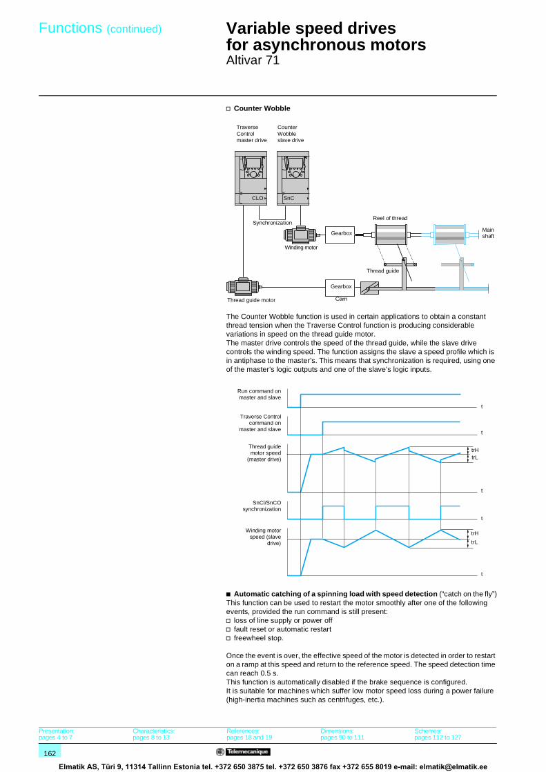
162
Functions (continued) 1 Variable speed drivesfor asynchronous motors 1
Altivar 71
v Counter Wobble
The Counter Wobble function is used in certain applications to obtain a constant thread tension when the Traverse Control function is producing considerable variations in speed on the thread guide motor.The master drive controls the speed of the thread guide, while the slave drive controls the winding speed. The function assigns the slave a speed profile which is in antiphase to the master’s. This means that synchronization is required, using one of the master’s logic outputs and one of the slave’s logic inputs.
b Automatic catching of a spinning load with speed detection (“catch on the fly”)This function can be used to restart the motor smoothly after one of the following events, provided the run command is still present: v loss of line supply or power offv fault reset or automatic restartv freewheel stop.
Once the event is over, the effective speed of the motor is detected in order to restart on a ramp at this speed and return to the reference speed. The speed detection time can reach 0.5 s.This function is automatically disabled if the brake sequence is configured.It is suitable for machines which suffer low motor speed loss during a power failure (high-inertia machines such as centrifuges, etc.).
TraverseControl master drive
CounterWobble slave drive
Gearbox
Reel of thread
Thread guide
Main
Thread guide motor
Gearbox
Cam
Winding motor
Synchronization
CLO SnC
shaft
Run command onmaster and slave
Traverse Controlcommand on
master and slave
SnCl/SnCOsynchronization
Winding motorspeed (slave
drive)
Thread guidemotor speed
(master drive)
t
t
t
t
t
trH
trL
trLtrH
Presentation:pages 4 to 7
Characteristics:pages 8 to 13
References:pages 18 and 19
Dimensions:pages 90 to 111
Schemes:pages 112 to 127
Elmatik AS, Türi 9, 11314 Tallinn Estonia tel. +372 650 3875 tel. +372 650 3876 fax +372 655 8019 e-mail: [email protected]

163
Functions (continued) 1 Variable speed drivesfor asynchronous motors 1
Altivar 71
b Undervoltage managementDepending on the application, it is possible to configure the Altivar 71’s response to undervoltages or power failures.If undervoltage occurs:v The Altivar 71 drive can continue operating with undervoltage levels up to -50% (adjustable threshold)v If the drive locks as a result, management of the fault relay can be configured (open or not). If the fault relay does not open an alarm is shown.
The Altivar 71 drive can also be configured to prevent the drive locking (using an alarm):v Controlled stop according to the type of stop configuredv Deceleration based on a ramp which it automatically adapts to maintain the DC bus voltage, thereby preventing the drive from locking in fault modev Instant IGBT (inverter bridge) loss followed by power supplied to the motor as soon as the line voltage has reappeared. This function can be used to prevent the Altivar 71 drive being reinitialized.
b Braking balanceWhen several drives are connected on a common DC bus, this function can be used to adjust the braking thresholds in order to balance the braking powers among the various drives or braking units.
b Braking resistor thermal protectionThe Altivar 71 drive incorporates thermal protection for braking resistors if it is not fitted with a thermal switch. If the resistor thermal state is too high an alarm can be assigned to the logic output or the drive may lock in fault mode, depending on how the function is programmed.
b Parameter set switching (multi-parameter)This can be used to switch 3 sets of 15 parameters maximum when the motor is running.Each set can contain a different value for each of the parameters. The sets are switched using 1 or 2 logic inputs or command word bits.
Function suitable for machines involving 2 or 3 manufacturing processes.
b Motor or configuration switching (multi-motor or multi-configuration)
The Altivar 71 drive can have 3 configurations, which can be activated remotely, allowing it to adapt to:v 2 or 3 different motors or mechanisms in multi-motor mode. In this instance, the thermal state for all the motors is calculated and saved. This means that each motor is protected thermally. v 2 or 3 configurations for the same motor in multi-configuration mode. This function can also be used to save the current configuration in another memory zone, which it can be retrieved from.Switching is carried out using 1 or 2 logic inputs, depending on the number of motors or configurations chosen (2 or 3).
Multi-motor and multi-configuration modes cannot be used together.
LIx
ATV 71
+ 24 V
LIy
M0 M1 M2
Configuration 0
Configuration 1
Configuration 2
LO or R
LO or R
LO or R
Configuration 2
Configuration 1
Configuration 0 if the two switches are open.
Schematic diagram for multi-motor mode
Presentation:pages 4 to 7
Characteristics:pages 8 to 13
References:pages 18 and 19
Dimensions:pages 90 to 111
Schemes:pages 112 to 127
Elmatik AS, Türi 9, 11314 Tallinn Estonia tel. +372 650 3875 tel. +372 650 3876 fax +372 655 8019 e-mail: [email protected]

164
Functions (continued) 1 Variable speed drivesfor asynchronous motors 1
Altivar 71
b Positioning on limit switches or position sensors This can be used to manage positioning based on limit switches or position sensors.
Activating the slowdown contact or stop contact allows the device to start in the other direction, even at high speed.
Slowdown mode can be configured: v The drive uses the validated ramp timev The drive calculates a ramp time according to the actual speed when the request to slow down is made. This calculation can be used to optimize the cycle time by limiting the time spent operating at low speed.
The stop type can also be configured:v stop on rampv freewheel stopv fast stop
b Short and long cam operationv Short camsIn this instance, when operating for the first time or after restoring the factory settings, the drive must initially be started outside the slowdown and stop zones in order to initialize the function.
v Long camsIn this instance, there is no restriction, which means that the function is initialized across the whole trajectory.
Example 1: limit switch positioningSlowdown and stopping occur when the sensor is changing state (open contact). It is possible to assign a command word bit or a logic input to disable the function in order to be able restart or not stop on the position.
Example 2: positioning on a target zoneThe disable contact can be used to restart in order to get past the target.
Forward slowdown
Forward stop
Reverse slowdown
Reverse stop
Reverse Forward
Rev
erse
slo
wdo
wn
For
war
d st
op
Rev
erse
sto
p
For
war
d sl
owdo
wn
Reverse
Forward low speed
Reverse low speed Forward
Trajectory
0
0
0
0
0
FWDslowdown
Forward
Reverse
FWDstop limit
Min. speed(LSP)
speed
Forward slowdown zone
Forward stop zone
Forwardslowdown
Forwardstop
Forward slowdown zone
Forward stop zone
Forwardslowdown
Forwardstop
Presentation:pages 4 to 7
Characteristics:pages 8 to 13
References:pages 18 and 19
Dimensions:pages 90 to 111
Schemes:pages 112 to 127
Elmatik AS, Türi 9, 11314 Tallinn Estonia tel. +372 650 3875 tel. +372 650 3876 fax +372 655 8019 e-mail: [email protected]

165
Functions (continued) 1 Variable speed drivesfor asynchronous motors 1
Altivar 71
b Reference switching Switching between two references (speed, torque, PID, etc.) can be enabled by:v a logic inputv a command word bitReference 1 (Fr1) is active if the logic input (or command word bit) is at 0; reference 2 (Fr1b) is active if the logic input (or command word bit) is at 1.References can be switched with the motor running.
Reference Fr1b, like Fr1, can originate from:v an analog input (AI)v a frequency control input (RP)v the graphic display terminalv the Modbus or CANopen busv a communication cardv the Controller Inside programmable card
b Operations on references (summing, subtraction, multiplication)Summing, subtraction and multiplication inputs can be activated simultaneously.
The drive reference is thus:v reference of drive A = (Fr1 or Fr1b + SA2 + SA3 - dA2 - dA3) x MA2 x MA3
v Summing inputsThey can be used to add 2 to 3 references from different sources to Fr1 or Fr1b (see “Reference switching”).The references to be added together are selected from all the possible types of reference.
For example, Reference Fr1 or Fr1b from AI1Reference SA2 from CANopenReference SA3 from a communication cardReference of drive A = Fr1 or Fr1b + SA2 + SA3.
v Subtraction inputsThey can be used to subtract 2 to 3 references from different sources from Fr1 or Fr1b (see “Reference switching”).The references to be subtracted are selected from all the possible types of reference.
For example, Reference Fr1 or Fr1b from AI1Reference dA2 from CANopenReference dA3 from a communication cardReference of drive A = Fr1 or Fr1b - dA2 - dA3.
v Multiplication inputs They can be used to multiply 2 to 3 references from different sources by Fr1 or Fr1b (see “Reference switching”).The references to be multiplied are selected from all the possible types of reference.
For example, Reference Fr1 or Fr1b from AI1Reference MA2 from CANopenReference MA3 from a communication cardReference of drive A = Fr1 or Fr1b x MA2 x MA3.
1
0
1
Fr1
Fr1b
LIx 0
f (Hz)
t
t
t
Forwardor
Reverse
Example of reference switching
SA2
SA3
dA2
dA3
MA2
MA3
A
A: drive referenceSA2, SA3: summed inputsdA2, dA3: subtraction inputsMA2, MA3: multiplication inputs.
Fr1 orFr1b
Presentation:pages 4 to 7
Characteristics:pages 8 to 13
References:pages 18 and 19
Dimensions:pages 90 to 111
Schemes:pages 112 to 127
Elmatik AS, Türi 9, 11314 Tallinn Estonia tel. +372 650 3875 tel. +372 650 3876 fax +372 655 8019 e-mail: [email protected]

166
Functions (continued) 1 Variable speed drivesfor asynchronous motors 1
Altivar 71
b PID regulatorThis can be used to regulate a process with a reference and feedback given by a sensor.Function suitable for controlling traction on a winder.
ACC: Acceleration, DEC: Deceleration, LI: Logic inputs, B: Speed reference.
v Internal references- rPI: reference transmitted by the graphic display terminal or a communication
network.- A: reference given by Fr1 or Fr1b with the summing, subtraction and
multiplication functions, as appropriate.The “PII” parameter is used to choose between these two references.
v Preset PID references 2 or 4 PID references are available. Table showing combinations of selected PID references:
v PID feedback PID feedback can be assigned to one of the analog inputs (AI1 to AI4), the frequency control input (RP) or the encoder, depending on the option cards present. It can also be transmitted by a communication network (AI network).
v Predictive speed referenceThis reference can come from the terminals (analog inputs, encoders, etc.), the graphic display terminal or a communication network.This speed input gives an initial reference for starting.
v Auto/Man.This can be used to switch from speed regulation mode (Man.) to PID regulation mode (Auto). A logic input or command word bit is used for switching.Speed regulation mode (Man.)The manual reference is transmitted via the terminals (analog inputs, encoder, preset speeds, etc.).With manual switching, the speed reference changes according to the ramp times ACC and DEC.PID regulation mode (Auto)In automatic mode it is possible to:
- adapt the references and feedback to the process (transformation)- correct a PID inversion- adjust the proportional, integral and derivative gains (Kp, Ki and Kd)- shunt the integral- use the “alarm” on the logic output or display it on the graphic display terminal, if
the threshold is exceeded (Max. feedback, Min. feedback and PID error) - display the PID reference, PID feedback, PID error and PID output on the graphic
display terminal and assign them to an analog output- apply a ramp (time = PrP) to the PID reference.
The motor speed is limited to between LSP and HSP.It is displayed as process values.
LIx (Pr4) LIy (Pr2) Reference0 0 rPI or A
0 1 rP2
1 0 rP31 1 rP4
+ +
+
PII
Pr2Pr4
PrP
rPI
A
LI
B
PIF
nOAI1
...AI4RP
PIC
FP1 x PSrACC DEC
tLSPAU
PIF1 / PIF2PIP1 / PIP2
nO
rP2rP3rP4
SP2...SP16...
rdG POH
POL
rIGrPG
PIM
nO
Ramp
PID
Gains
Ramps
Error inversion
Restart error threshold(wake-up)
Predictive speed referenceScaling
Manual reference
Preset manual references
EncoderNetwork AI
Internal references
Preset PID references
(man.)
Auto/Man.
Presentation:pages 4 to 7
Characteristics:pages 8 to 13
References:pages 18 and 19
Dimensions:pages 90 to 111
Schemes:pages 112 to 127
Elmatik AS, Türi 9, 11314 Tallinn Estonia tel. +372 650 3875 tel. +372 650 3876 fax +372 655 8019 e-mail: [email protected]
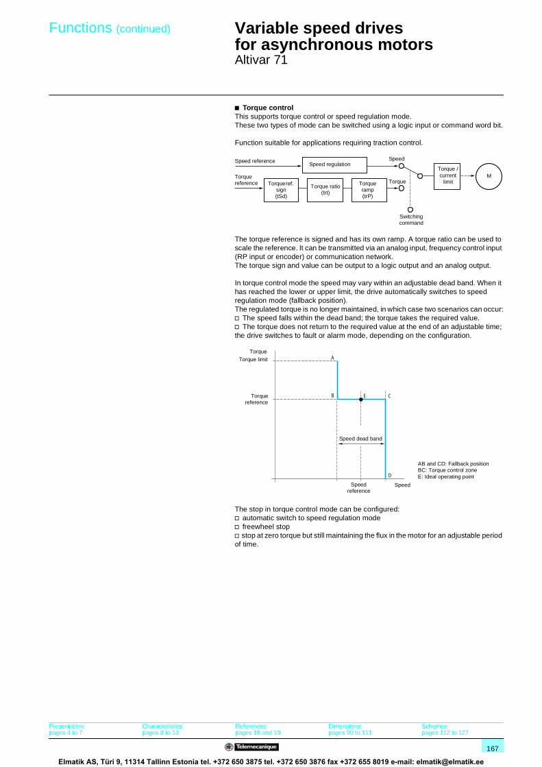
167
Functions (continued) 1 Variable speed drivesfor asynchronous motors 1
Altivar 71
b Torque controlThis supports torque control or speed regulation mode.These two types of mode can be switched using a logic input or command word bit.
Function suitable for applications requiring traction control.
The torque reference is signed and has its own ramp. A torque ratio can be used to scale the reference. It can be transmitted via an analog input, frequency control input (RP input or encoder) or communication network.The torque sign and value can be output to a logic output and an analog output.
In torque control mode the speed may vary within an adjustable dead band. When it has reached the lower or upper limit, the drive automatically switches to speed regulation mode (fallback position).The regulated torque is no longer maintained, in which case two scenarios can occur:v The speed falls within the dead band; the torque takes the required value.v The torque does not return to the required value at the end of an adjustable time; the drive switches to fault or alarm mode, depending on the configuration.
The stop in torque control mode can be configured:v automatic switch to speed regulation modev freewheel stopv stop at zero torque but still maintaining the flux in the motor for an adjustable period of time.
Speed reference
Torque reference Torque ref.
sign(tSd)
Torque ratio(trt)
Torque ramp(trP)
Speed regulationSpeed
Torque
Torque / current
limitM
Switching command
A
B E C
D
Speed dead band
Torque limitTorque
Torquereference
SpeedSpeed reference
AB and CD: Fallback positionBC: Torque control zoneE: Ideal operating point
Presentation:pages 4 to 7
Characteristics:pages 8 to 13
References:pages 18 and 19
Dimensions:pages 90 to 111
Schemes:pages 112 to 127
Elmatik AS, Türi 9, 11314 Tallinn Estonia tel. +372 650 3875 tel. +372 650 3876 fax +372 655 8019 e-mail: [email protected]

168
Functions (continued) 1 Variable speed drivesfor asynchronous motors 1
Altivar 71
b Torque limitThis can be used to limit the torque in the motor and generator quadrants using separate settings.
There are two types of torque limit:v one with a value set by a parameterv the other with a value given by an analog input, frequency control input or encoder.
When both torque limit types are enabled it is the lowest value which is read. They can be switched using a logic input or command word bit.
This function is not available for voltage/frequency ratio.
The torque limit operates in both directions of rotation in motor or generator mode.
b Torque or current limit detectionThis function can be used to detect when the current or torque limit has been reached. Depending on the configuration, it is possible to:v use an alarm to signal thisv lock the drive after an adjustable period of time.
b Current limit A 2nd current limit can be configured between 0 and 1.65 times the drive nominal current and it can be used to limit the rise in motor temperature and the torque.Switching between 2 current limits can be enabled via:v a logic inputv a command word bit
150 %
100 %
150 %
100 %
Speed –
Reverse operation
Generator modeReversespeed –torque +
Motor modeForwardspeed +torque +
Motor modeReversespeed –torque –
Generator modeForwardspeed +torque –
Speed +
Forward
Torque +
Torque –Overload rangeMotor torqueTorque limit
6.4 A
LI6
7.9 A:
:
:
+0.00HzTerm2nd CURRENT LIMIT.
Current limitation
0.0A
I Limit. 2 value
QuickCode
RDY
I Limit. 2 activ.
Configuring current switching
5221
70
Presentation:pages 4 to 7
Characteristics:pages 8 to 13
References:pages 18 and 19
Dimensions:pages 90 to 111
Schemes:pages 112 to 127
Elmatik AS, Türi 9, 11314 Tallinn Estonia tel. +372 650 3875 tel. +372 650 3876 fax +372 655 8019 e-mail: [email protected]

169
Functions (continued) 1 Variable speed drivesfor asynchronous motors 1
Altivar 71
b Reference saving This can be used to:v Read and save the speed reference value of the analog input using a logic input when the command lasts longer than 0.1 sv Control the speed of several drives alternately via a single analog reference and a logic input for each drivev Enable via a logic input a line reference (serial link) on several drives in order to synchronize movements by eliminating variations when the reference is sentThe reference is acquired 100 ms after the rising edge of the request.A new reference is not then acquired until a new request is made.
b Stop typesv Freewheel stop This can be used to stop the motor by resistive torque only if the supply to the motor is removed.
A freewheel stop is achieved:- by configuring a normal stop command as a freewheel stop (when a run
command is over or a stop command occurs)- by enabling a logic input- by activating a command word bit
v Fast stopThis can be used to achieve a braked stop with an acceptable deceleration ramp time (divided by an adjustable coefficient from 0 to 10) for the drive/motor unit to avoid locking in the event of an overbraking fault. If the coefficient is equal to 0 the motor decelerates as fast as possible.
This is used for conveyors with emergency stop electrical braking.A fast stop is achieved:
- by configuring a normal stop as a fast stop (when a run command is over or a stop command occurs)
- by enabling a logic input- by activating a command word bit
v Fastest possible stopIf the ramp divider coefficient is equal to 0 the motor decelerates as fast as possible.
v DC injection stopThis can be used to brake high-inertia machines at low speed or maintain torque on stopping.A DC injection stop is achieved:
- by configuring a normal stop as a DC injection stop (when a run command is over or a stop command occurs)
- by enabling a logic input- by activating a command word bit
The DC value and the standstill braking time are adjustable.
0
0
1
0
1
100 ms 100 ms100 ms
t
t
t
Example of how reference saving works
F: motor frequency
Run command
LIx (saved)
Analog reference
NO
Ramp stop
LI4
0
NO
:
:
:
:
:
+0.00HzTermSTOP CONFIGURATION
Fast stop assign.
0.0A
Freewheel assign.
Ramp divider
DC inject. assign.
QuickCode
RDY
Type of stop
Configuring stop types
522
142
Presentation:pages 4 to 7
Characteristics:pages 8 to 13
References:pages 18 and 19
Dimensions:pages 90 to 111
Schemes:pages 112 to 127
Elmatik AS, Türi 9, 11314 Tallinn Estonia tel. +372 650 3875 tel. +372 650 3876 fax +372 655 8019 e-mail: [email protected]

170
Functions (continued) 1 Variable speed drivesfor asynchronous motors 1
Altivar 71
b Motor thermal protectionMotor thermal protection is provided by the drive:v directly, through PTC probes located in the motor windingsv indirectly, via the integrated thermal relay. Indirect thermal protection is implemented via continuous calculation of its theoretical temperature rise.
The microprocessor calculates the theoretical temperature rise of the motor based on various elements:v the operating frequencyv the current taken by the motorv the operating timev the maximum ambient temperature around the motor (40°C)v the type of motor ventilation (self-cooled or force-cooled)
Thermal protection can be adjusted from 0.2 to 1.5 times the nominal drive current. It must be adjusted to the nominal current indicated on the motor rating plate.
Note: The motor thermal state memory returns to zero when the drive control part is switched off.
v Self-cooled motors:The tripping curves vary with the motor frequency.
v Force-cooled motors:Only the 50 Hz tripping curve should be considered, whatever the motor frequency.
b Drive thermal protectionThe drive’s thermal protection is provided by a PTC probe fitted on the heatsink or integrated with the power module.
b IGBT thermal protectionThe drive manages the switching frequency intelligently according to the IGBT temperature.If the drive’s current rating is exceeded (e.g. current higher than the nominal drive current for a zero stator frequency), an alarm is displayed and a timer increases for as long the alarm is present.
(a 16 min)
10 000(a 2 h 45)
1 000
1000,7 0,8 0,9 1 1,1 1,2 1,3 1,4 1,5 1,6
5020101 3 5 Hz
Trip
tim
e in
sec
onds
Motor current/ItH
Motor thermal protection curves
t
Presentation:pages 4 to 7
Characteristics:pages 8 to 13
References:pages 18 and 19
Dimensions:pages 90 to 111
Schemes:pages 112 to 127
Elmatik AS, Türi 9, 11314 Tallinn Estonia tel. +372 650 3875 tel. +372 650 3876 fax +372 655 8019 e-mail: [email protected]

171
Functions (continued) 1 Variable speed drivesfor asynchronous motors 1
Altivar 71
b Configuring the drive’s fault response (fault management) Different responses can be configured for the drive in the event of a resettable fault occurring: v freewheel stopv drive switches to the fallback speedv drive maintains the speed at which it was operating when the fault occurred until the fault disappearsv stop on rampv fast stopv DC injection stopv no stop (alarm activated)
List of resettable faults:v external faultv speed feedback lossv overspeedv slippingv output phase lossv auto-tuning faultv brake contactor feedback faultv encoder couplingv loss of 4-20mAv PTC probev drive overheatingv motor overload if the thermal state is less than 100%v line overvoltagev overbrakingv current/torque limitv IGBT overheatingv communication faults (Modbus, CANopen and other communication networks)
b Resetting resettable faults This can be used to remove the last fault using a logic input, command word bit or the STOP/RESET key on the graphic display terminal. The restart conditions after a reset to zero are the same as those of a normal power-up.List of resettable faults, see “Configuring the drive’s fault response”.Line supply undervoltage and input phase loss faults are reset automatically when the line supply is restored.
Function suitable for applications where drives are difficult to access, for example, a drive placed on a moving part.
b General reset (disables all faults)This function can be used to disable all faults, including thermal protection (forced operation) and may cause irreparable damage to the drive.
Function suitable for applications where restarting may be crucial (conveyor in an oven, smoke extraction system, machines with solidifying products to be discarded).The function is enabled by a logic input.Fault monitoring is active if the logic input is at state 1.All faults are reset on a change of state of the logic input.
Note: Use of this function invalidates the guarantee.
+0.00HzTerm4-20mA LOSS
Ramp stop
0.0A
Spd maintain
Fast stop
DC injection
Quick
RDY
Fallback spd
Configuration of the drive’s fault response
522
143
Presentation:pages 4 to 7
Characteristics:pages 8 to 13
References:pages 18 and 19
Dimensions:pages 90 to 111
Schemes:pages 112 to 127
Elmatik AS, Türi 9, 11314 Tallinn Estonia tel. +372 650 3875 tel. +372 650 3876 fax +372 655 8019 e-mail: [email protected]

172
Functions (continued) 1 Variable speed drivesfor asynchronous motors 1
Altivar 71
b Automatic restartThis enables the drive to be restarted automatically after it has locked in fault mode if the relevant fault has disappeared and the other operating conditions permit a restart.This restart is performed by a series of automatic attempts separated by increasingly longer waiting periods of 1 s, 5 s, 10 s then 1 minute for the rest.The options for the restart process’s duration are 5, 10 and 30 min., 1, 2, 3 hours and an unlimited time.If the drive has not restarted after the configured time, it will lock and the procedure is abandoned until it has been switched off and on again.
The faults which allow the drive to be restarted in this way are:v line overvoltagev motor thermal overloadv drive thermal overloadv DC bus overvoltagev line phase failurev external faultv loss of 4-20mAv PTC probev serial linkv current or torque limitv output phase lossv line voltage too low. For this fault, the function is always active, even if it is not configured.v fault caused by CANopen, Modbus or other commmunication networks. These faults are reset automatically as soon as the command word or frequency reference is sent to the drive.For these types of fault, the relay configured as a fault relay remains activated if the function is configured. The speed reference and operating direction must be maintained for this function.
This function is suitable for machines or installations which are in continuous operation or unmonitored, and where a restart will not endanger equipment or personnel in any way.
b PTC probe protectionThe probes can be connected directly to the drive’s control card or to the I/O option cards.The way in which a temperature fault is recorded by the drive can be configured:v permanent recordv only recorded when the drive’s power section is switched onv only recorded when the motor is running
b IGBT testingWhen enabled, this function tests every IGBT and the motor connections in order to detect a short-circuit or an open circuit. This test is run every time the drive is powered on and before each motor start.
This function must not be enabled with machines with fast cycles in order to preserve the time for recording run commands.
b Resetting operating time to zeroThe drive’s operating and power-up time can be reset.
b External faultThis function can lead to the drive locking if a fault occurs in the machine. This fault is flagged on the drive display unit. The fault is flagged if the signal is at 1 or 0, according to the function’s configuration.
Presentation:pages 4 to 7
Characteristics:pages 8 to 13
References:pages 18 and 19
Dimensions:pages 90 to 111
Schemes:pages 112 to 127
Elmatik AS, Türi 9, 11314 Tallinn Estonia tel. +372 650 3875 tel. +372 650 3876 fax +372 655 8019 e-mail: [email protected]

173
Functions (continued) 1 Variable speed drivesfor asynchronous motors 1
Altivar 71
b Line contactor controlThis can be used on each run command to close the line contactor and open it when the motor is no longer on. The drive’s control section must be powered without fail by an external 24 V c source.
This function must be used for simple sequences with a low number of Start/Stop operations (Start/Stop cycle longer than 60 seconds).
After a run command, if the line contactor is not closed the drive will lock after an adjustable period of time.
b Forced local modeForced local mode imposes control via the terminals or graphic display terminal and disables all other control modes.Switching to forced local mode may be activated via:v a logic inputv a function key on the graphic display terminal
The following references and commands are available for forced local mode: v references AI1, AI2, etc. and command via logic inputsv reference and command via the graphic display terminal
00
V
24 V
WU V LO/R
LI P24
LIn
L1 L2 L3
M 3
ATV 71
K10
K10
KM1 K11
K11
Emergencystop
Line 3 a
Run
Forwardor reverse
External source 24 V c
Presentation:pages 4 to 7
Characteristics:pages 8 to 13
References:pages 18 and 19
Dimensions:pages 90 to 111
Schemes:pages 112 to 127
Elmatik AS, Türi 9, 11314 Tallinn Estonia tel. +372 650 3875 tel. +372 650 3876 fax +372 655 8019 e-mail: [email protected]

174
Functions 1 Variable speed drivesfor asynchronous motors 1
Altivar 71
Function compatibility tableb Configurable I/OFunctions which are not listed in this table are fully compatible.Stop functions have priority over run commands.The selection of functions is limited:v By the number of drive I/O which can be reassigned: if necessary, add an I/O extension card.v By the incompatibility of certain functions with one another.
Functions Operationon the references
+/- speed (3) Limit switch management
Preset speeds
PID regulator Traversecontrol
Jog operation Brake control
Operation on the references
A A+/- speed (3)
Limit switch management
Preset speedsX A
PID regulator
Traverse control
Jog operationX X
Brake control
Automatic catching a spinning load with speed detection (catch on the fly)Control and integrity check of output contactor
DC injection stop
Fast stop
Freewheel stop
+/- speed around a reference
High-speed hoisting
Torque control
Load sharing
Position control via limit switches
(1) Torque control and the speed reference functions are only incompatible if torque control mode is active.(2) Priority is given to the first of these two stop modes to be activated.(3) Excluding special use with reference channel Fr2.
Incompatible functions Priority functions (functions which cannot be active at the same time)
Compatible functions X The arrow indicates which function has priority.
N/A A Example: The "Freewheel stop" function has priority over the "Fast stop" function.
(1) (1) (1) (1) (1)(1) (1)
Elmatik AS, Türi 9, 11314 Tallinn Estonia tel. +372 650 3875 tel. +372 650 3876 fax +372 655 8019 e-mail: [email protected]

175
1
1
Automatic catching a spinning load with speed detection (catch on the fly)
Control and integrity check of output contactor
DC injection stop
Fast stop Freewheel stop
+/- speed around a reference
High-speed hoisting
Torque control
Load sharing Position control via limit switches
A
A
X X
(1)
(1)
(1)
(1)
(1)
(1)
(1)
(1)
(2)
(2)
(1)
(1) (1) (1)
(1)
Elmatik AS, Türi 9, 11314 Tallinn Estonia tel. +372 650 3875 tel. +372 650 3876 fax +372 655 8019 e-mail: [email protected]

176
Presentation,functions 1
PowerSuite software workshop 1
The PowerSuite software workshop is a user-friendly tool designed for setting up control devices for the following Telemecanique brand motors:b TeSys model U controller-startersb Altistart soft start/soft stop unitsb Altivar variable speed drivesIt includes various functions designed for setup phases such as:b Preparing configurations (for PC)b Start-up (for PC and Pocket PC)b Maintenance (for PC and Pocket PC)In order to simplify the start-up and maintenance phases, the PowerSuite software workshop can use the Bluetooth® wireless link.
Preparing configurationsThe PowerSuite software workshop can be used on its own to generate the device configuration. It can be:b Saved, printed and exported to office automation softwareb Exchanged between a PC and a Pocket PC using standard synchronization software such as Microsoft ActivSync®
The PowerSuite software workshop can also be used to convert:b An Altivar 28 drive configuration to an Altivar 31 drive configurationb An Altivar 58 or Altivar 58F drive configuration to an Altivar 71 drive configuration
SetupWhen the PC is connected to the device, the PowerSuite software workshop can be used to:b Transfer the generated configurationb Adjustb Monitor: This option has been enhanced with new functions such as:v The oscilloscopev The high speed oscilloscope (minimum time base: 2 ms)v Display of communication parametersb Controlb Save the final configuration
MaintenanceIn order to simplify maintenance operations, the PowerSuite software workshop can be used to:b Compare the configuration of a device currently being used with a saved configurationb Manage the user’s installed base of equipment, in particular:v Organize the installed base into folders (electrical equipment, machinery, workshops, etc)v Store maintenance messagesv Simplify Ethernet connection by storing the IP address
User interfaceThe PowerSuite software workshop can be used to:b Present the device parameters arranged by function in the form of illustrated views of diagrams or simple tablesb Customize the parameter namesb Create:v A user menu (choice of particular parameters)v Monitoring control panels with graphic elements (cursor, gauges)b Perform sort operations on the parametersb Display text in five languages (English, French, German, Italian and Spanish). The language changes immediately and there is no need to restart the program.
It also has online contextual help:b On the PowerSuite toolb On the device functions by direct access to the user’s manuals.
(1) Some functions are not available for all devices. See the table of function availability, page 177.
Presentation
PowerSuite software workshop for PCFunctions (1)
5331
80
PowerSuite screen on PCManagement of the installed base
533
181
PowerSuite screen on PCView of PI regulator function parameters
5331
82
PowerSuite screen on PCMonitoring control panel (cursor, gauge)
References:page 179
Elmatik AS, Türi 9, 11314 Tallinn Estonia tel. +372 650 3875 tel. +372 650 3876 fax +372 655 8019 e-mail: [email protected]

177
Functions (continued) 1 PowerSuite software workshop 1
Availability of functions for the PowerSuite software workshop for PCFunctions not listed in the table are available for all devices.Function available with devices Controller-
starterSoft start/soft stop unit
Drives
TeSys model U
ATS 48 ATV 11 ATV 31 ATV 38 ATV 58ATV 58F
ATV 68 ATV 71
MonitoringOscilloscopeHigh speed oscilloscopeDisplay of communication parametersControlCustomization of parameter namesCreation of a user menuCreation of monitoring control panelsSort operation on parameters
Functions available Functions not available
ConnectionsModbus communication bus The PowerSuite software workshop for PC can be connected directly to the device terminal port or Modbus network port via the serial port on the PC.
Two types of connection are possible:b With a single device (point-to-point connection)b With a number of devices (multidrop connection)
Note: The Altivar 68 drive uses a specific protocol for point-to-point connection. Multidrop connection is not available.
Ethernet TCP/IP communication network The PowerSuite software workshop for PC can be connected to an Ethernet network (see pages 180 to 185). In this case, the devices can be accessed:b Using a 174 CEV 300 20 Ethernet-Modbus bridgeb Using a VW A3 310 communication card for the Altivar 71 driveb Using a VW3 A58 310 communication card for the Altivar 38, 58 and 58F drives
Bluetooth® wireless link (2)The PowerSuite software workshop for PC can communicate via a Bluetooth® radio link with a device equipped with a Bluetooth® - Modbus VW3 A8 114 adaptor. The adaptor plugs into the device terminal port or Modbus network port, and has a range of 10 m (class 2).
If the PC does not have Bluetooth® technology, use the VW3 A8 115 USB-Bluetooth®
adaptor.
Remote maintenanceUsing a simple Ethernet connection, the PowerSuite software workshop can be used for remote monitoring and diagnostics.When devices are not connected to the Ethernet network, or it is not directly accessible, various remote transmission solutions may be possible (modem, teleprocessing gateway, etc). Please consult your Regional Sales Office.
Hardware and software environmentsThe PowerSuite software workshop for PC can operate in the following PC environments and configurations:b Microsoft Windows® 98 SE, Microsoft Windows® 2000, Microsoft Windows® XPb Pentium III, 800 MHz, hard disk with 300 Mb available, 128 Mb RAMb SVGA or higher definition monitor
(1) Please consult our specialist “Automation platform Modicon Premium and Unity - PL7 software“ and “Automation platform Modicon TSX Micro - PL7 software” catalogues.
(2) Not available for Altivar 11 and Altivar 68 drives.
RS 232RS 485
533
183
Modbus multidrop connection
Modbus bus
ATV 31 ATV 38 ATV 71 TeSys model U
PowerSuite
ATS 48
XGS Z24
533
184
Ethernet connection
Bridge
PLC (1)
Ethernet TCP/IP network
ATV 31 ATS 48 ATV 38 ATV 71
Modbus bus
PowerSuite
Presentation:page 176
References:page 179
Elmatik AS, Türi 9, 11314 Tallinn Estonia tel. +372 650 3875 tel. +372 650 3876 fax +372 655 8019 e-mail: [email protected]

178
Functions (continued) 1 PowerSuite software workshop 1
PowerSuite software workshop for Pocket PC (1) Functions
Start-upWhen the Pocket PC is connected to the device, the PowerSuite software workshop can be used to:b Transfer the configurationb Adjustb Monitor (2)b Control (2)b Save the final configuration
MaintenanceIt can be used to compare the configuration of a device currently being used with a saved configuration.
User interfaceThe PowerSuite software workshop for Pocket PC can be installed in a single language selected from the five available (English, French, German, Italian and Spanish).
ConnectionsModbus communication bus The PowerSuite software workshop for Pocket PC can be connected directly to the device terminal port or Modbus network port via the serial port on the Pocket PC.
The Modbus connection kit is connected via the Pocket PC serial synchronization cable. This cable must be ordered from the supplier of the Pocket PC.It can only be connected to a single device, in point-to-point connection.
Hardware and software environmentsThe PowerSuite software workshop version V2.0.0 for Pocket PC is compatible with Pocket PCs equipped with a Microsoft Windows® for Pocket PC 2002 or Microsoft Windows MobileTM 2003 operating system and an ARM or XSCALE processor.Performance tests for the PowerSuite software workshop version V2.0.0 have been carried out with the following Pocket PCs:b Hewlett Packard® IPAQ 2210b Compaq® IPAQ series 3800 and 3900b Hewlett Packard® Jornada series 560
(1) The PowerSuite software workshop for Pocket PC is not compatible with the Altivar 68 and Altivar 71 variable speed drives.
(2) Not available for the Altivar 11 variable speed drive.
Acceleration
File Zoom Tools Help
Adjustments
High Speed
3,0 50,0
inout
PowerSuite screen on Pocket PCAdjustments
5331
85
Presentation:page 176
References:page 179
Elmatik AS, Türi 9, 11314 Tallinn Estonia tel. +372 650 3875 tel. +372 650 3876 fax +372 655 8019 e-mail: [email protected]

179
References 1 PowerSuite software workshop 1
ReferencesPowerSuite software workshop for PC or Pocket PCDescription Composition Reference Weight
kgPowerSuite CD-ROM b 1 program for PC and for Pocket PC in English, French,
German, Italian and Spanishb Technical documentationb ABC configurator program for the LUF Pp communication
gateways
VW3 A8 104 0.100
PowerSuite update CD-ROM (1)
b 1 program for PC and for Pocket PC in English, French, German, Italian and Spanish
b Technical documentation and ABC configurator program
VW3 A8 105 0.100
Connection kit for PC serial port
b 1 x 3 m cable with 2 RJ 45 connectorsb 1 RS 232/RS 485 converter with one 9-way female
SUB-D connector and one RJ 45 connectorb 1 RJ45/9-way SUB-D adaptor for connecting ATV 38/58/58F
drivesb 1 RJ45/9-way SUB-D adaptor for connecting ATV 68 drivesb 1 converter for the ATV 11 drive, with one 4-way male
connector and one RJ45 connector
VW3 A8 106 0.350
Connection kit for Pocket PC serial port (2)
b 1 x 0.6 m cable with 2 RJ 45 connectorsb 1 RS 232/RS 485 converter with one 9-way male
SUB-D connector and one RJ 45 connectorb 1 RJ45/9-way SUB-D adaptor for connecting ATV 38/58/58F
drivesb 1 converter for the ATV 11 drive, with one 4-way male
connector and one RJ45 connector
VW3 A8 111 0.300
Modbus-Bluetooth® adaptor (3)
b 1 Bluetooth® adaptor (10 m range, class 2) with 1 RJ45 connector
b 1 x 0.1 m cable with 2 RJ 45 connectors for PowerSuiteb 1 x 0.1 m cable with 1 RJ 45 connector and 1 mini DIN
connector, for TwidoSoftb 1 RJ45/9-way SUB-D adaptor for connecting ATV 38/58/58F
drives
VW3 A8 114 0.155
USB-Bluetooth® adaptor for PC
This adaptor is required for a PC which is not equippedwith Bluetooth® technology. It is connected to a USB port on the PC.Range of 10 m (class 2).
VW3 A8 115 0.290
RS 232-RS 485 interface b 1 Modbus multidrop converter for connection to screw terminals. Requires a 24 V c (20...30 V), 20 mA power supply (4).
XGS Z24 0.105
(1) Updates a version u V1.40 with the latest available version. For versions < V1.40, you should order the PowerSuite CD-ROM, VW3 A8 104.
(2) This kit connects to the serial synchronization cable, which must be ordered separately from the supplier of the Pocket PC.(3) Can also be used to communicate between a Twido PLC and the TwidoSoft software workshop.(4) Please consult our specialist “Interfaces, I/O splitter box and power supply” catalogue.
CompatibilityConnection Controller-
starterSoft start/soft stop unit
Drives
TeSys model U
ATS 48 ATV 11 ATV 31 ATV 38 ATV 58ATV 58F
ATV 68 ATV 71
Compatibility of the PowerSuite software workshop for PC with the following devices (minimum version)Modbus serial link (ATV 68: specific protocol) V1.40 V1.30 V1.40 V2.0 V1.40 V1.0 V1.50 V2.2Ethernet (device equipped with an Ethernet TCP/IP card) V1.50 V1.50 V2.2Ethernet via Modbus Ethernet bridge V1.50 V2.0 V1.50 V1.50 V2.2Bluetooth® V2.2 V2.2 V2.2 V2.2 V2.2 V2.2
Compatibility of the PowerSuite software workshop for Pocket PC with the following devices (minimum version)Modbus serial link V1.50 V1.30 V1.40 V2.0 V1.40 V1.20
Compatibility of the PowerSuite software workshop with Pocket PCsConnection Operating system Performance tested models PowerSuite software versions
V2.0 V1.50 V1.40 V1.30Modbus serial link Windows MobileTM 2003 for Pocket PC Hewlett Packard® IPAQ 2210
Windows® for Pocket PC 2002 Compaq® IPAQ series 3800, 3900
Hewlett Packard® Jornada series 560Windows® for Pocket PC 2000 Hewlett Packard® Jornada 525, 545, 548
Windows® CE Hewlett Packard® Jornada 420
Compatible devices and/or software versionsIncompatible devices and/or software versions
VW3 A8 104
5331
87
VW3 A8 114
533
188
Presentation:page 176
Functions:pages 176 to 178
Elmatik AS, Türi 9, 11314 Tallinn Estonia tel. +372 650 3875 tel. +372 650 3876 fax +372 655 8019 e-mail: [email protected]

180
Presentation 1 Starters, drivesand communication 1
Ethernet TCP/IP networkTransparent Ready concept
PresentationIntroduced by Schneider Electric, the Transparent Ready concept enables transparent communication between control system devices, production and management. Network technologies and the associated new services are used to share and distribute data between sensors, PLCs, workstations and third-party devices in an increasingly efficient manner. Web servers embedded in the network components and control system devices can be used to: b Access configuration data transparentlyb Perform remote diagnosticsb Incorporate simple human/machine interface functions
This concept is based on the Ethernet TCP/IP industrial standard which proposes a single network that meets most communication requirements fromsensors/actuators through to production management systems.Where a variety of communication systems are usually required, Transparent Ready standard technologies can result in significant cost savings in the areas of definition, installation, maintenance or training.
Transparent Ready is based on:b Ethernet TCP/IP-based services meeting control system requirements in terms of functions, performance and quality of servicesb Products including several ranges of PLC, distributed I/O, industrial terminals, variable speed drives, gateways and an increasing number of partner productsb The ConneXium range of cabling accessories: hubs, switches, cables adapted to the environment and to the requirements of industrial conditions.
Services based on Ethernet TCP/IP
The following Altivar variable speed drives can be connected to the Ethernet TCP/IP network:b Altivar 38 drive via a VW3 A58 310 communication cardb Altivar 71 drive via a VW3 A3 310 communication cardThese cards are supplied with a standard Web server. It is fully modifiable by the user according to the application (JAVA or FactoryCast development tool).
Services
Applica- tions
Transport
Link
Physical
Network manage-ment
GlobalData
FDR automatic reconfiguration
WebServer
Messa-ging
ModbusI/OScanning
SNMP NDDS DHCP TFTP FTP HTTP Modbus
UDP TCP
IP
Ethernet 802.3 and Ethernet II
MIB
Tra
nsp
aren
t R
ead
y
Characteristics:page 181
Functions:pages 181 to 183
Connections:page 184
References:pages 184 and 185
Elmatik AS, Türi 9, 11314 Tallinn Estonia tel. +372 650 3875 tel. +372 650 3876 fax +372 655 8019 e-mail: [email protected]

181
Characteristics,functions 1
Starters, drivesand communication 1
Ethernet TCP/IP networkTransparent Ready concept
CharacteristicsStructure Topology Industrial local area network conforming to ANSI/IEEE 802.3 (4th edition 1993-07-08)
Star networkTransmission mode Manchester baseband. Half-duplex or full-duplex
Data rate 10/100 Mbps with automatic recognition
Medium STP double shielded twisted pair, impedance 100 Ω ± 15 Ω for 10 BASE-T or category 5 Ethernet cable, conforming to standard TIA/EIA-568A
Length of network 100 m maximum between Hub or switch and a station
Type of device ATV 38, ATV 71Universal services HTTP, BOOTP, DHCP, FTP, TFTP, SNMP
Transparent Ready services Modbus messaging, IO Scanning, FDR
Universal servicesHTTP “Hypertext Transfer Protocol” (RFC 1945)
HTTP “Hypertext Transfer Protocol” is a protocol used to transmit Web pages between a server and a browser. HTTP has been used on the Web since 1990.
Web servers embedded in control system devices are at the heart of the Transparent Ready concept and provide easy access to devices anywhere in the world using a standard web browser such as Internet Explorer or Netscape Navigator.
BOOTP/DHCP (RFC 1531)
BOOTP/DHCP is used to supply devices (client) automatically with IP addresses and parameters. This avoids having to manage the addresses of each device individually by transferring their management to a server.BOOTP identifies the client device by its Ethernet MAC address. This address is unique to each device, and should be entered in the server each time the device is changed.DHCP “Dynamic Host Configuration Protocol” identifies the client device by a name in plain language (“Device Name”) which is maintained throughout the application (eg: “Conveyor 23”).
Altivar 71 and Altivar 38 drives can be given a name (“Device Name”) by the terminal or the PowerSuite software workshop.Telemecanique has used the standard BOOTP/DHCP protocols in order to offer the faulty device replacement (FDR) service.
FTP “File Transfer Protocol” (RFCs 959, 2228, and 2640)
FTP (File Transfer Protocol) supplies the standard file sharing elements. The FTP protocol is used by numerous systems to exchange files between devices.
Transparent Ready devices implement FTP in order to transfer certain data from or to devices, especially for downloading firmware or custom Web pages.
SNMP “Simple Network Management Protocol” (RFCs 1155, 1156 and 1157)
The Internet community has developed the SNMP standard to enable management of the various network components by means of a single system. The network management system can exchange data with SNMP agent devices. This function allows the manager to view the status of the network and products, to modify their configuration and to feed back alarms in the event of a fault.
Transparent Ready devices are compatible with SNMP and can be integrated naturally into a network administered via SNMP.
Presentation:page 180
Connections:page 184
References:pages 184 and 185
Elmatik AS, Türi 9, 11314 Tallinn Estonia tel. +372 650 3875 tel. +372 650 3876 fax +372 655 8019 e-mail: [email protected]

182
Functions (continued) 1 Starters, drivesand communication 1
Ethernet TCP/IP networkTransparent Ready concept
Transparent Ready servicesModbus communication standard
Modbus, the industry communication standard since 1979, has been ported to Ethernet TCP/IP, the backbone of the Internet revolution, to create Modbus TCP/IP, a totally open protocol on Ethernet. There is no need for any proprietary component, nor the purchase of a licence in order to develop a connection to Modbus TCP/IP.This protocol can easily be ported to any device supporting a standard TCP/IP communication stack. The specifications can be obtained free of charge from the web site: www.modbus.org.
Modbus TCP, simple and open
The Modbus application layer is very simple and universally familiar. Thousands of manufacturers are already implementing this protocol. Many have already developed a Modbus TCP/IP connection and numerous products are currently available.The simplicity of Modbus TCP/IP enables any small field device, such as an I/O module, to communicate on Ethernet without the need for a powerful microprocessor or a large amount of internal memory.
Modbus TCP, high performance
Due to the simplicity of its protocol and the fast data rate of Ethernet 100 Mbps, the performance of Modbus TCP/IP is excellent. This means that this type of network can be used in realtime applications such as I/O Scanning.
I/O Scanning serviceSchematic diagram
The Altivar 38 and Altivar 71 drives accept the I/O scanning service generated by:b The following automation platforms:v Premium equipped with a TSX ETY 410/5101 modulev Quantumv Momentum M1Eb A PC equipped with Modbus communication software with the I/O scanner functionThis service is used to manage the exchange of remote I/O on the Ethernet network after simple configuration and without the need for special programming.
The drive I/O are scanned transparently by means of read/write requests according to the Modbus master/slave protocol on the TCP/IP profile.
The “I/O Scanning” service can be configured, activated or deactivated by:b The PowerSuite software workshopb The standard Web server
Read Write%MW word table
Premium
Ethernet TCP/IP
Input wordsDrive output words
Altivar 38 Altivar 71 Altivar 71
Momentum
Presentation:page 180
Characteristics:page 181
Connections:page 184
References:pages 184 and 185
Elmatik AS, Türi 9, 11314 Tallinn Estonia tel. +372 650 3875 tel. +372 650 3876 fax +372 655 8019 e-mail: [email protected]

183
Functions (continued) 1 Starters, drivesand communication 1
Ethernet TCP/IP networkTransparent Ready concept
Transparent Ready services (continued)Faulty Device Replacement (FDR) service
The FDR service uses standard BOOTP, DHCP, file management and TFTP technologies in the aim of simplifying the maintenance of Ethernet devices.It is used to replace a faulty device with a new product, ensuring its detection, reconfiguration and automatic restarting by the system, without the need for any delicate manual intervention.
The main steps are:b A device using the FDR service becomes faulty.b A similar device is taken out of the maintenance reserve base, preconfigured with the “Device_name” of the faulty device, then reinstalled on the network.b The FDR server (which can be a Quantum or Premium PLC Ethernet module) detects the new arrival, configures it with its IP address and transfers all its configuration parameters to it.b The substituted device checks that the parameters are fully compatible with its own characteristics, then switches to operational mode.
Web serverThe Ethernet cards in Altivar 38 and Altivar 71 drives incorporate a standard Web server, in English.The functions provided by this Web server require no special configuration or programming of the PC supporting the Internet browser. Using a password, two levels of access can be defined to the web server: read-only or modification.
The standard Web server provides access to the following functions:b Altivar Viewerb Data Editorb Ethernet Statisticsb Securityb Etc
The standard Web server can be adapted or replaced by a customized Web server depending on the requirements of the application. Knowledge of HTTP protocol and JAVA technology is required in order to make modifications.
Presentation:page 180
Characteristics:page 181
Connections:page 184
References:pages 184 and 185
Elmatik AS, Türi 9, 11314 Tallinn Estonia tel. +372 650 3875 tel. +372 650 3876 fax +372 655 8019 e-mail: [email protected]

184
Connections,references 1
Starters, drivesand communication 1
Ethernet TCP/IP networkTransparent Ready concept
Connections
Ethernet network connection elementsCommunication interfacesDescription For devices Reference Weight
kgCommunication cards equipped with an RJ45 connectorEthernet Modbus TCP/IP 10/100 Mbps Class B 20
ATV 38 (1) VW3 A58 310 0.300
ATV 71 VW3 A3 310 0.300
Ethernet/Modbus bridgewith 1 x 10BASE-T/100BASE-TX Ethernet port (RJ45 type)
ATS 48ATV 31
174 CEV 300 20 (2)
0.500
Connecting cablesDescription Used Length Reference (3) Weight
From To m kgStraight shielded twisted pair cables2 RJ45 connectors
ATV 38 (+VW3 A3 310 communication card),ATV 71 (+VW3 A3 310 communication card),Ethernet/Modbus bridge174 CEV 300 20
499 NpH 1pp 10 hubs, 499 NpS 171 00 switches
2 490 NTW 000 02 –
5 490 NTW 000 05 –
12 490 NTW 000 12 –
40 490 NTW 000 40 –
80 490 NTW 000 80 –
Cable for Modbus bus1 RJ45 connector and one stripped end
ATS 48, ATV 31
Ethernet/Modbus bridge174 CEV 300 20
3 VW3 A8 306 D30 –
(1) At 100 Mbps, connection of the VW3 A58 310 communication card on the Ethernet network via a switch only authorizes data exchange in “Half Duplex” mode. It is vital to use the hubs or switches recommended above on which it is possible to configure “Half Duplex” mode.
(2) Please consult our specialist “Automation platform Modicon Premium and Unity - PL7 software” catalogue.(3) Cable conforming to category 5 EIA/TIA-568 standard and IEC 1180/EN 50 173, class D. For UL and CSA 22.1 approved
cables, add the letter U at the end of the reference. Example: 490 NTW 000 02 becomes 490 NTW 000 02U.
ATV 71 Magelis XBT ATV 71 ATS 48
Transceiver
Hub
Switch
Redundant fibre optic ring 200 Mbps Full-duplex
Switch
Transceiver
Switch
Hub
Quantum
HubPremium
Hub Hub
Fibre optic loop
Optical fibre
ATV 71ATV 38ATV 31 ATS 48 Advantys STB Momentum
GatewayGateway
Premium
522
077
174 CEV 300 20
Presentation:page 180
Characteristics:page 181
Functions:pages 181 to 183
Elmatik AS, Türi 9, 11314 Tallinn Estonia tel. +372 650 3875 tel. +372 650 3876 fax +372 655 8019 e-mail: [email protected]

185
References (continued) 1 Starters, drivesand communication 1
Ethernet TCP/IP networkTransparent Ready concept
Ethernet network connection elements (continued)Accessories (1)
Description Type of Ethernet network Available ports Reference Weightkg
Hubs (2) 10 Mbps 4 x 10BASE-T ports 499 NEH 104 10 0.530
3 x 10BASE-T ports2 x 10BASE-FL ports
499 NOH 105 10 0.900
100 Mbps 4 x 100BASE-TX ports 499 NEH 141 10 0.240
Switches (2) 10/100 Mbps 5 x 10BASE-T/100BASE-TX ports2 x 100BASE-TX ports
499 NES 171 00 0.460
5 x 10BASE-T/100BASE-TX ports2 x 100BASE-FX ports
499 NOS 171 00 0.460
(1) For Transparent Ready accessories, please consult our specialist “Ethernet TCP/IP, Transparent Factory” catalogue.(2) At 100 Mbps, connection of the VW3 A58 310 communication card on the Ethernet network via a switch only authorizes data
exchange in “Half Duplex” mode. It is vital to use the hubs or switches recommended above on which it is possible to configure “Half Duplex” mode.
530
141
499 NEH 104 10
530
142
499 NES 171 00
Presentation:page 180
Characteristics:page 181
Functions:pages 181 to 183
Connections:page 184
Elmatik AS, Türi 9, 11314 Tallinn Estonia tel. +372 650 3875 tel. +372 650 3876 fax +372 655 8019 e-mail: [email protected]

186
Presentation 1 Starters, drivesand communication 1
Communication via Fipio bus
(1) Please consult our specialist “Automation platform Modicon Premium and Unity - PL7 software” catalogue.
(2) Please consult our specialist “Automation platform Modicon TSX Micro and PL7 software” catalogue.
(3) Please consult our specialist “Human/Machine interfaces” catalogue.(4) Please consult our specialist “Distributed I/O Advantys STB” catalogue.(5) Please consult our specialist “Modicon Momentum Automation platform” catalogue.
Presentation
The Fipio fieldbus is a standard means of communication between control system components, and conforms to the World FIP standard.A Premium PLC (bus manager) can control 127 devices (agents) over a maximum distance of 15 km.The Fipio bus manager is integrated in the PLC processor.
The Altistart 48 soft start/soft stop unit and the Altivar 31 variable speed drive can be connected to the Fipio bus via an LUF P1 Fipio/Modbus gateway.
The following Altivar variable speed drives are connected to the Fipio network via a communication card:b VW3 A58 311 card for the Altivar 38 driveb VW3 A3 311 card for the Altivar 71 drive
The following devices can also be connected to the Fipio bus:b TSX Micro (2) or Premium Agent function (1) PLCsb The CCX 17 operator panel (2)b The Magelis XBT-F terminal with graphic screen (3) b The Magelis iPC industrial PC (3)b Advantys STB IP 20 distributed I/O (4)b Discrete, analog or application-specific Momentum distributed I/O (5)b Discrete or analog (IP 20) TBX distributed I/O (1)b TBX discrete (IP 65) or TSX EpF (IP67) dust and damp proof distributed I/O (1)b The TBX SAP 10 Fipio/AS-Interface gateway (1) b The LUF P1 Fipio/Modbus gatewayb A PC terminal b Partner products in the Collaborative Automation programme
Fipio bus
Premium
AdvantysSTB
ATV 71 ATV 38
ATS 48
LUF P1
ATV 31
Magelis XBT
Characteristics: page 187
Connections:page 188
References: pages 188 and 189
Elmatik AS, Türi 9, 11314 Tallinn Estonia tel. +372 650 3875 tel. +372 650 3876 fax +372 655 8019 e-mail: [email protected]

187
Characteristics 1 Starters, drivesand communication 1
Communication via Fipio bus
CharacteristicsStructure Topology Industrial bus conforming to the World FIP standard
Subscribers linked via daisy-chain or tap junctions
Access method Producer/consumer principleBus management by a fixed arbitrator (bus manager)
Transmission mode Baseband physical layer on shielded twisted pair, according to standard NF C 46-604
Data rate 1 Mbps
Medium Shielded twisted pair 150 Ω.Optical fibre 62.5/125 with the use of electrical/fibre optic repeaters
Number of subscribers 32 maximum per segment1 manager + 127 agents maximum over all segmentsThe number of Fipio agents is limited by the memory capacity of Premium processors(62 Altivar drives maximum) (1)
Number of segments Unlimited in tree or star architecturesLimited to 5 cascaded segmentsThe link between 2 subscribers may cross 4 electrical or electrical/fibre optic repeaters maximum
Length of bus 15,000 m maximum1,000 m maximum without repeater for an electrical segment5,000 m maximum for 5 electrical segments3,000 m maximum for 1 fibre optic segment
Type of device ATS 48, ATV 31 ATV 38 ATV 71Type of interface LUF P1 VW3 A58 311 VW3 A3 311
Profile FED C 32P FED C 32 FED C 32
Control and adjustment 26 configurable words (2) 5 predefined words 8 configurable words (communication scanner)
Monitoring 26 configurable words (2) 8 predefined words 8 configurable words (communication scanner)
Configuration and adjustment 1 indexed wordRead/write access to all functions by the PLC application program
(1) Please consult our specialist “Automation platform Modicon Premium and Unity - PL7 software” catalogue.
(2) 26 words in total for control and monitoring. To extend the I/O capacity to 26 control words and 26 monitoring words, use the ABC Configurator software (see page 179).
Presentation: page 186
Connections:page 188
References: pages 188 and 189
Elmatik AS, Türi 9, 11314 Tallinn Estonia tel. +372 650 3875 tel. +372 650 3876 fax +372 655 8019 e-mail: [email protected]

188
Connections,references 1
Starters, drivesand communication 1
Communication via Fipio bus
Fipio wiring system
Elements for connecting the Fipio bus and a Premium PLC (1)Cards and gatewayDescription Used
forCode Reference Weight
kgFipio cardThe card is equipped with a9-way male SUB-D connector, which can take a TSX FP ACC12 connector with a TSX FP CAp00 trunk cable or TSX FP CCp00 drop cable.
ATV 38 1 VW3 A58 311 0.300
Standard Fipio cardThe card is equipped with a9-way male SUB-D connector, which can take a TSX FP ACC12 connector with a TSX FP CAp00 trunk cable or TSX FP CCp00 drop cable.This card should be used for new installations. It is also used to replace an ATV 58 or ATV 58F equipped with a VW3 A58 311 card by an ATV 71.
ATV 71 2 VW3 A3 311 0.300
Substitution Fipio cardThe card is equipped with a9-way male SUB-D connector, which can take a TSX FP ACC12 connector with a TSX FP CAp00 trunk cable or TSX FP CCp00 drop cable.This Fipio communication card is reserved for replacing an ATV 58 or ATV 58F equipped with a VW3 A58 301 card by an ATV 71.
ATV 71 2 VW3 A3 301 0.300
Fipio/Modbus gatewayThe gateway is equipped with:b 1 Fipio 9-way male SUB-D connector
which will take a TSX FP ACC12 connector for use with a TSX FP CAp00 trunk cable or TSX FPCCp00 drop cable
b 1 RJ45 connector for Modbus for connection with the VW3 A8 306 Rpp cableFit an external 24 V c power supply, 100 mA minimum, to be ordered separately (2).
ATS 48ATV 31
3 LUF P1 0.240
(1) To order other elements for connection to the Fipio bus, please consult our specialist “Automation platform Modicon Premium and Unity - PL7 software” catalogue.
(2) Please consult our specialist “Interfaces, I/O splitter boxes and power supplies” catalogue.
5
6
6
6
44
4
1
646 6
14
9
7
11 111111
1413
12
10
8
8
14
11
11
4
32 2
c 19…60 V
c 19…60 V
c 24…48 V
ATV 38
ATS 48ATV 31
ATV 71ATV 71Premium
LUF P1
533
148
Presentation: page 186
Characteristics: page 187
Elmatik AS, Türi 9, 11314 Tallinn Estonia tel. +372 650 3875 tel. +372 650 3876 fax +372 655 8019 e-mail: [email protected]

189
References (continued) 1 Starters, drivesand communication 1
Communication via Fipio bus
Elements for connecting the Fipio bus and a Premium PLC (continued) (1)
AccessoriesDescription Use Code Unit reference Weight
kgFemale connector for device with 9-way female SUB-D connector(polycarbonate, IP 20)
Connection via daisy-chain or tap junctions. For ATV 38, ATV 71, LUF P1 gatewayand Premium PLC
4 TSX FP ACC12 0.040
Tap junction(polycarbonate, IP 20)
Trunk cable tap link 5 TSX FP ACC14 0.120
Fipio line terminators(sold in lots of 2)
Connector, tap junctionand repeater
6 TSX FP ACC7 0.020
Electrical repeater(IP 65)Power supply 24…48 V c, 150 mA (2)
Increases the length of the bus while enabling connection of 2 segments of 1000 m maximum
7 TSX FP ACC6 0.520
Electrical/fibre optic repeater(IP 65)Power supply 19…60 Vc, 210 mA (2)
Used for connection(via a patch panel) of an electrical segment (1000 m max.) and a fibre optic segment (3000 m max.)
8 TSX FP ACC8M 0.620
Modbus splitter blockequipped with 10 RJ45 connectorsand 1 screw terminal
Used to connect an ATV 31, ATS 48 on the LUP P1 gateway
9 LU9 GC3 0.500
Modbus line terminators (3) LU9 GC3 Modbus splitter block 10 VW3 A8 306 RC 0.010FIP wiring test tool Used to test each section of a network
segment– TSX FP ACC9 0.050
Connecting cables (1)Description Used Code Length Reference Weight
From To m kgTrunk cables8 mm, 1 shielded twisted pair 150 Ω.In standard atmosphere (4) and inside buildings
TSX FP ACC12 connector,TSX FP ACC14 junction box,TSX FP ACC6, ACC8M repeaters
TSX FP ACC12 connector,TSX FP ACC14 junction box, TSX FP ACC6 repeater
11 100 TSX FP CA100 5.680200 TSX FP CA200 10.920
500 TSX FP CA500 30.000
Trunk cables9.5 mm, 1 shielded twisted pair 150 Ω. In harsh environments (5), outside buildings or in mobile installations (6)
TSX FP ACC12 connector,TSX FP ACC14 junction box,TSX FP ACC6, ACC8M repeaters
TSX FP ACC12 connector,TSX FP ACC14 junction box, TSX FP ACC6 repeater
11 100 TSX FP CR100 7.680
200 TSX FP CR200 14.920500 TSX FP CR500 40.000
Drop cables8 mm, 2 shielded twisted pairs 150 Ω.In standard atmosphere (4) and inside buildings
TSX FP ACC12 connector
TSX FP ACC14 junction box
12 100 TSX FP CC100 5.680
200 TSX FP CC200 10.920
500 TSX FP CC500 30.000
Fibre optic jumperDouble optical fibre 62.5/125
TSX FP ACC8M repeater
Patch panel 13 2 TSX FP JF020 0.550
Cables for Modbus bus2 RJ45 connectors
LUF P1 gateway,ATS 48,ATV 31
LU9 GC3 Modbus splitter block
14 0.3 VW3 A8 306 R03 0.025
1 VW3 A8 306 R10 0.0603 VW3 A8 306 R30 0.130
DocumentationThe manuals and quick reference guides for starters and variable speed drives, as well as the user manuals for communication gateways, are available on the web site: www.telemecanique.com.(1) To order other elements for connection to the Fipio bus, please consult our specialist “Automation platform Modicon Premium
and Unity - PL7 software” catalogue.(2) Please consult our specialist “Interfaces, I/O splitter boxes and power supplies” catalogue.(3) Sold in lots of 2.(4) Standard environment:
- no particular environmental constraints- operating temperature between + 5°C and + 60°C- fixed installation
(5) Harsh environment: - withstand to hydrocarbons, industrial oils, detergents, solder splashes- relative humidity up to 100%- saline atmosphere- significant temperature variations- operating temperature between -10°C and +70°C- mobile installation
(6) Mobile installation: cables in accordance with VDE 472 part 603/H:- use on a cable-carrier chain with bending radius 75 mm minimum- use on a gantry, provided that operating conditions such as acceleration, speed, length, etc are adhered to: please consult your Regional Sales Office- unauthorised use on robots, or multi-axis applications
Presentation: page 186
Characteristics: page 187
Connections:page 188
Elmatik AS, Türi 9, 11314 Tallinn Estonia tel. +372 650 3875 tel. +372 650 3876 fax +372 655 8019 e-mail: [email protected]

190
Presentation,characteristics 1
Starters, drivesand communication 1
Communication via Modbus bus
Presentation
Modbus is a master/slave protocol.
Two exchange mechanisms are possible:b Request/response: The request from the master is addressed to a given slave. The master then waits for the response from the slave which has been interrogated.b Broadcasting: The master broadcasts a request to all the slave stations on the bus, which execute the command without transmitting a response.
The Altistart 48 soft start/soft stop unit, Altivar 31 and Altivar 38 variable speed drives are connected to the Modbus bus via their terminal port.On the Altivar 38 drive, the terminal port can be freed up for connection of the operator terminal by using a communication card. The Altivar 71 variable speed drive includes the Modbus protocol as standard. It can be accessed directly by means of 2 integrated communication ports:b A terminal port for connection of the graphic display terminal or an industrial HMI terminal (Magelis type)b Modbus network portAs an option, the Altivar 71 drive can also be equipped with a VW3 A3 303 Modbus/Uni-Telway communication card which offers additional characteristics (4-wire RS 485, ASCII mode, etc).
CharacteristicsType of device ATS 48 ATV 31 ATV 38 ATV 71 ATV 71 ATV 38, ATV 71Type of connection Terminal port Network port Communication card
Structure Connector RJ45 RJ45 9-way female SUB-D
RJ45 RJ45 9-way female SUB-D
Topology Bus
Physical interface 2-wire RS 485 2-wire or 4-wire RS 485Access method Master/slave
Transmission mode RTU RTU or ASCII
Data rate 38.4 Kbps – – – – p –19.2 or 9.6 Kbps p p p p p p4.8 Kbps p p – – p p
Medium Double shielded twisted pairNumber of subscribers 18, 27 or 31 slaves, depending on polarization (1)
Type of polarization 4.7 kΩ pulldown resistors
No pulldown
4.7 kΩ pulldown resistors
No pulldown
No pulldown Configurable.No pulldown or 4.7 kΩ pulldown resistors
Length of bus 1000 or 1300 m excluding tap links, depending on polarization (1)
Tap link 3 or 20 m maximum, depending on polarization (1)
(1) See the configuration table on page 191.
Quantum
PremiumTSX Micro Twido
ATV 31
ATV 71 ATV 38ATS 48
Modbus bus
Connections:pages 191 and 192
References:pages 191 to 193
Elmatik AS, Türi 9, 11314 Tallinn Estonia tel. +372 650 3875 tel. +372 650 3876 fax +372 655 8019 e-mail: [email protected]

191
Connections,references 1
Starters, drivesand communication 1
Communication via Modbus bus
Configuration on the basis of polarizationThe specification of the physical layer provided by standard RS 485 is incomplete. Various polarization diagrams can therefore be applied depending on the environment in which the equipment is to be used.The Modbus standard specifies the polarization exactly (1).
MasterWith polarization4.7 kΩ
With polarization470 Ω
Slave Without polarization
Configuration not recommended. Modbus type configuration31 slaves.Length of bus: 1,300 mTap link: 3 m maximum.RC line terminators(R =120 Ω, C = 1 nF).
With polarization4.7 kΩ
Uni-Telway type configuration27 slaves.Length of bus: 1,000 mTap link: 20 m maximum.RC line terminators(R =120 Ω, C = 1 nF).
Mixed configuration18 slaves.Length of bus: 1,000 mTap link: 20 m maximum.RC line terminators(R =120 Ω, C = 1 nF).
Connection elements for RJ45 wiring systemCardDescription Used with Reference Weight
kgCommunication cardequipped with one 9-way female SUB-D connector
ATV 71 VW3 A3 303 0.300
AccessoriesDescription Code Unit reference Weight
kgModbus splitter block10 RJ45 connectors and 1 screw terminal block
1 LU9 GC3 0.500
Modbus T-junction boxes With integrated cable (0.3 m)
2 VW3 A8 306 TF03 –
With integrated cable (1 m)
2 VW3 A8 306 TF10 –
Line terminators For RJ45 connector(3)
R = 120 ΩC = 1 nF
3 VW3 A8 306 RC 0.200
R = 150 Ω 3 VW3 A8 306 R 0.010
CablesDescription Used Code Length Reference Weight
From To m kgCables forModbus bus2 RJ45 connectors
ATS 48,ATV 31, ATV 71(connector ports or Modbus network)
VW3 A8 306 TFpp Modbus T-junction boxLU9 GC3 Modbus splitter block
LU9 GC3 Modbus splitter block
VW3 A8 306 TFpp Modbus T-junction boxLU9 GC3 Modbus splitter block
4 0.3 VW3 A8 306 R03 0.025
1 VW3 A8 306 R10 0.060
3 VW3 A8 306 R30 0.130
Cables forModbus busOne 9-way male SUB-D connector and one RJ45 connector
ATV 38(terminal port)ATV 38(+VW3 A58 303 kit)ATV 71 (+ VW3 A3 303 communication card)
LU9 GC3 Modbus splitter block
4 1 VW3 A58 306 R10 0.080
3 VW3 A58 306 R30 0.150
Double shielded twisted pair cables
LU9 GC3 Modbus splitter block(screw terminals)
LU9 GC3 Modbus splitter block(screw terminals)
5 100 TSX CSA 100 5.680
200 TSX CSA 200 10.920
500 TSX CSA 500 30.000
(1) Standard defined in 2002, available on the web site: www.modbus.org.(2) The cable for connecting the PLC and the splitter block depends on the type of PLC ; please consult our specialist “Automation
platform Modicon Premium and Unity - PL7 software”, “Automation platform Modicon Quantum”, “Automation platform Modicon TSX Micro and PL7 software” and “Automation and relay functions” catalogues.
(3) Sold in lots of 2.
34
2 2
4
41
5
42 2 3
(2)
Starters/drives
PLC
LU9 GC3
522
184
VW3 A8 306 TFpp
5321
74
Presentation:page 190
Characteristics:page 190
Elmatik AS, Türi 9, 11314 Tallinn Estonia tel. +372 650 3875 tel. +372 650 3876 fax +372 655 8019 e-mail: [email protected]

192
Connections,references (continued) 1
Starters, drivesand communication 1
Communication via Modbus bus
(1) The cable for connecting the PLC and the splitter block depends on the type of PLC ; please consult our specialist “Automation platform Modicon Premium and Unity - PL7 software”, “Automation platform Modicon Quantum”, “Automation platform Modicon TSX Micro and PL7 software” and “Automation and relay functions” catalogues.
Connection elements using tap junctionsKitDescription Used with For protocol Reference Weight
kgCommunication kitcomprising:b 1 communication card equipped
with one 9-way female SUB-D connectorb 1 x 3 m cable equipped with:v One 9-way male SUB-D connector for connection
to the communication cardv One 15-way male SUB-D connector for connection
to a TSX SCA 62 subscriber socketb 1 “Modbus, Uni-Telway” user’s manual
ATV 38with operator terminal
Uni-Telway, Modbus ASCII, Modbus RTU/Jbus
VW3 A58 303 0.300
AccessoriesDescription Code Reference Weight
kgTap junction3 screw terminals, RC line terminator
1 TSX SCA 50 0.520
Subscriber socketTwo 15-way female SUB-D connectors and 2 screw terminals, RC line terminator
2 TSX SCA 62 0.570
CablesDescription Used Code Length Reference Weight
From To m kgDouble shielded twisted pair cables
TSX SCA 50 junction box,TSX SCA 62 subscriber socket
TSX SCA 50 junction box,TSX SCA 62 subscriber socket
3 100 TSX CSA 100 5.680
200 TSX CSA 200 10.920
500 TSX CSA 500 30.000
Cable for Modbus bus1 RJ45 connector and one stripped end
ATS 48,ATV 31, ATV 71(terminal ports or Modbus network)
TSX SCA 50 junction box
4 3 VW3 A8 306 D30 0.150
Cable for Modbus bus1 RJ45 connector andone 15-way male SUB-D connector
ATS 48,ATV 31, ATV 71(terminal ports or Modbus network)
TSX SCA 62 subscriber socket
5 3 VW3 A8 306 0.150
Cable for Uni-Telway and Modbus bus2 male SUB-D connectors,9 and 15-way
ATV 71 (+ VW3 A3 303 communication card)
TSX SCA 62 subscriber socket
5 3 VW3 A8 306 2 0.150
3
5 4
2 1(1)
Starters/drives
PLC
TSX SCA 50
5331
78
TSX SCA 62
5331
79
Presentation:page 190
Characteristics:page 190
Elmatik AS, Türi 9, 11314 Tallinn Estonia tel. +372 650 3875 tel. +372 650 3876 fax +372 655 8019 e-mail: [email protected]

193
References (continued) 1 Starters, drivesand communication 1
Communication via Modbus bus
Connection elements using tap junctions (continued)CablesDescription Used For
protocolReference Weight
kgFrom ToRS 485 connection kit comprising: b 1 x 3 m cable equipped with:v One 9-way male SUB-D
connector v One 15-way male SUB-D
connectorb 1 “RS 485” user’s manual b 1 “Communication variables”
user's manual
ATV 38without operator terminal(terminal port)
TSX SCA 62 subscriber socket
ModbusRTU
VW3 A58 306 0.300
Connection elements using screw terminalsAccessoriesDescription Unit reference Weight
kgLine terminators (1)for screw terminals
R = 120 Ω, C = 1 nF
VW3 A8 306 DRC 0.200
R = 150 Ω VW3 A8 306 DR 0.200
CableDescription Used Length Reference Weight
From To m kgCable for Modbus1 RJ45 connector and one stripped end
ATS 48,ATV 31, ATV 71(terminal ports or Modbus network)
Standard screw terminals, TSX SCA 50 junction box
3 VW3 A8 306 D30 0.150
DocumentationThe manuals and quick reference guides for starters and variable speed drives, as well as the user manuals for communication gateways, are available on the web site: www.telemecanique.com.
(1) Sold in lots of 2.
Presentation:page 190
Characteristics:page 190
Connections:pages 191 and 192
Elmatik AS, Türi 9, 11314 Tallinn Estonia tel. +372 650 3875 tel. +372 650 3876 fax +372 655 8019 e-mail: [email protected]

194
Presentation 1 Starters, drivesand communication 1
Communication via Modbus Plus network
Presentation
The Modbus Plus network is a high-performance industrial local area network which can be used to meet the needs of client/server type extended architectures, combining a high data rate (1 Mbps), simple low-cost transmission media and numerous messaging services.
The Altistart 48 soft start/soft stop unit and the Altivar 31 variable speed drive can be connected to the Modbus Plus network via an NW BM85000 gateway which has four RS 232 serial ports.
The following Altivar variable speed drives are connected to the Modbus Plus network via a communication card:b VW3 A58 302 card for the Altivar 38 driveb VW3 A3 302 card for the Altivar 71 drive
Communication services
The main data exchange services between subscribers connected to the network are:b The “Modbus messaging” service according to Modbus protocolb The “Global Data” service: each subscriber makes available 32 words for each of the 63 other network subscribersb The “Peer Cop” dialogue service: point-to-point transaction of 32 receive or transmit words
The “Global Data” and “Peer Cop” services are restricted to a Modbus Plus network with a maximum of 64 subscribers.
Altivar 38 and Altivar 71 drives are accessed by simple configuration in the PLC using “Peer Cop” and “Global Data” services.These services enable rapid exchange of the main drive parameters:b The “Peer Cop” service for controlling and adjusting the driveb The “Global data” service for monitoring the drive
Other parameters, which are used less frequently, can be accessed by the Modbus messaging service.
Modbus Plus network
Quantum
ATV 38
ATS 48
ATV 71
Premium
Advantys STB
Gateway
ATV 31
Characteristics: page 195
Connections:page 196
References: pages 196 and 197
Elmatik AS, Türi 9, 11314 Tallinn Estonia tel. +372 650 3875 tel. +372 650 3876 fax +372 655 8019 e-mail: [email protected]

195
Characteristics 1 Starters, drivesand communication 1
Communication via Modbus Plus network
CharacteristicsStructure Topology Bus
Physical interface RS 485
Access method Token bus
Transmission mode HDLC synchronous
Data rate 1 Mbps
Medium Shielded twisted pair 120 Ω Optical fibre
Number of subscribers per network
32, without repeater64, with one or more repeaters
Number of networks 4, separated by a maximum of 3 bridges
Length of network 450 m maximum without repeater1800 m maximum with 3 electrical repeaters3000 m between 2 fibre optic repeaters
Services Modbus messaging Point-to-point requests with confirmation report: 200 bytes maximum, compatible with all Modbus subscribers
“Global Data” 4096-byte shared databaseCyclic exchange of 32 broadcast wordsLimited to one networkThis service does not cross bridges
“Peer Cop” dialogue Point-to-point or broadcast messageLimited to one networkThis service does not cross bridges
Type of device ATS 48, ATV 31 ATV 38 ATV 71Type of interface NW BM85000 VW3 A58 302 VW3 A3 302
Control “Modbus messaging” “Peer Cop”32 predefined words maximum
“Peer Cop”8 configurable words maximum (communication scanner)
Monitoring “Modbus messaging” “Global Data”32 predefined words maximum
“Global Data”8 configurable words maximum (communication scanner)
Configuration and adjustment “Modbus messaging” “Modbus messaging”Read/write access to all drive parameters
Presentation: page 194
Connections:page 196
References: pages 196 and 197
Elmatik AS, Türi 9, 11314 Tallinn Estonia tel. +372 650 3875 tel. +372 650 3876 fax +372 655 8019 e-mail: [email protected]

196
Connections,references 1
Starters, drivesand communication 1
Communication via Modbus Plus network
Modbus Plus wiring system
Modbus Plus bus connection elements (1)
Cards and gatewaysDescription Used with Code Reference Weight
kgCommunication cardsequipped with one 9-way female SUB-D connector
ATV 38 1 VW3 A58 302 0.300ATV 71 1 VW3 A3 302 0.300
Modbus Plus/Modbus gateway4 RS 232 portspower supply 115…220 Va
ATS 48, ATV 31 2 NW BM85000 3.158
RS 232/RS 485 interfacepower supply 24 V c, 20 mA (2)
ATS 48, ATV 31 3 XGS Z24 0.105
Connection accessoriesDescription Use Code Reference Weight
kgModbus Plus tap(IP 20)
For connecting via a tap junction 4 990 NAD 230 00 0.230
Modbus Plus in-line connector Gateway, bridge and repeater 5 AS MBKT 085 0.035Connector with Modbus Plus terminator(sold in lots of 2)
Bridge and repeater 6 AS MBKT 185 0.260
Modbus Plus electrical repeater Extension beyond 450 m orup to 64 subscribers
7 NW RR85 001 2.677
Modbus Plus bridge with 4 ports
Connection of 4 networks maximum 8 NW BP85 002 2.813
Line/station fibre optic repeater
– 9 490 NRP 254 00 2.856
Point-to-point fibre optic repeater
Used to connect an electrical segment to the fibre optic segment (3000 m maximum)
– NW NRP 253 00 2.863
Wiring tool Inserting trunk and drop cables in a 990 NAD 230 00 tap
– 043 509 383 3.000
(1) To order other connection elements, please consult our specialist “Automation platform Modicon Premium and Unity - PL7 software” and “Automation platform Modicon Quantum” catalogues.
(2) Please consult our specialist “Interfaces, I/O splitter boxes and power supplies” catalogue.
RS 232
RS 485
7
1313
116
12 2
13
3
11
11
1 1
6
9
10
11
11
10 4
10 54 4 4
44
8
Network # 1
Network # 2Premium
Quantum
ATV 38
ATV 31ATS 48
ATV 71
Quantum
Fib
re o
ptic
link
Presentation: page 194
Characteristics: page 195
Elmatik AS, Türi 9, 11314 Tallinn Estonia tel. +372 650 3875 tel. +372 650 3876 fax +372 655 8019 e-mail: [email protected]

197
References (continued) 1 Starters, drivesand communication 1
Communication via Modbus Plus network
(1) To order other connection elements, please consult our specialist “Automation platform Modicon Premium and Unity - PL7 software” and “Automation platform Modicon Quantum” catalogues.
Modbus Plus bus connection elements (continued) (1)
CablesDescription Used Code Length Reference Weight
From To m kgTrunk cables forModbus Plus
990 NAD 230 00 Modbus Plus tap
990 NAD 230 00 Modbus Plus tap,AS MBKT 085 Modbus Plus in-line connector,Modbus Plus connector with terminatorsAS MBKT 185
10 30.5 490 NAA 271 01 1.833
152.5 490 NAA 271 02 10.135
305 490 NAA 271 03 18.940
457 490 NAA 271 04 30.000
1525 490 NAA 271 06 112.950
Drop cablesOne 9-way male SUB-D connector and onestripped end
ATV 38 (+VW3 A58 302 communication card), Premium, Quantum PLCs, NW BP85 002 Modbus Plus bridge with 4 ports, 490 NRP 253 00 line/station fibre optic repeater
990 NAD 230 00 Modbus Plus tap
11 2.4 990 NAD 211 10 0.169
6 990 NAD 211 30 0.459
ATV 71(+ VW3 A3 302 communication card)
990 NAD 230 00 Modbus Plus tap
12 2.4 990 NAD 219 10 0.142
6 990 NAD 219 30 0.465
Cable for Modbus1 RJ45 connector and one stripped end
ATS 48, ATV 31, NW BM85000 Modbus Plus/Modbus gateway
RS 232/RS 485 interface
13 3 VW3 A8 306 D30 0.115
Presentation: page 194
Characteristics: page 195
Connections:page 196
Elmatik AS, Türi 9, 11314 Tallinn Estonia tel. +372 650 3875 tel. +372 650 3876 fax +372 655 8019 e-mail: [email protected]
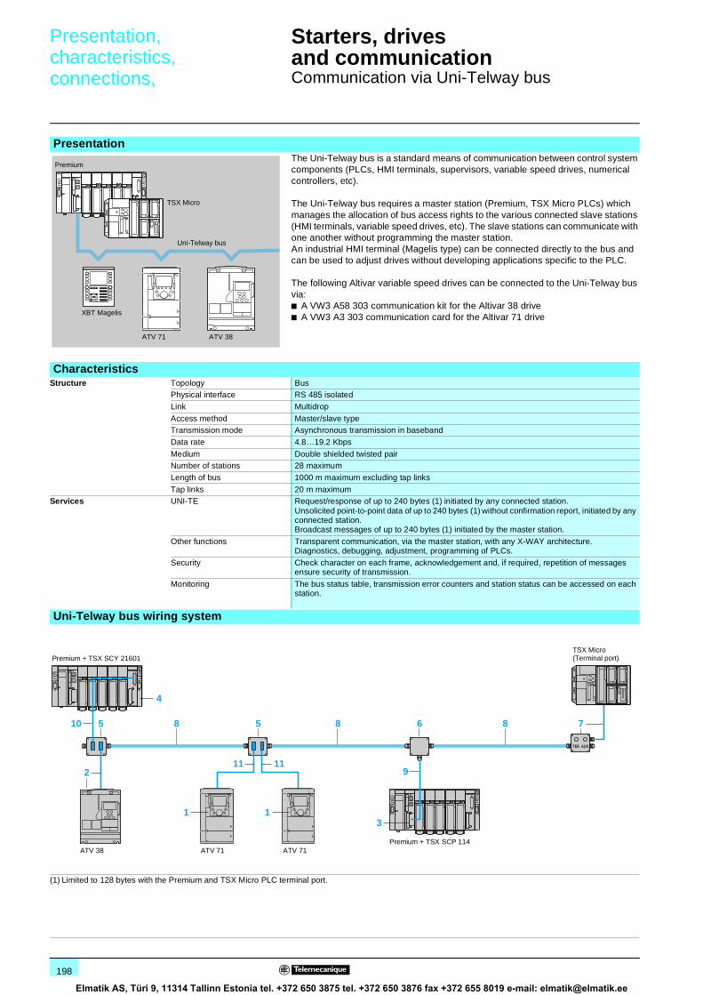
198
Presentation,characteristics,connections, 1
Starters, drivesand communication 1
Communication via Uni-Telway bus
Presentation The Uni-Telway bus is a standard means of communication between control system components (PLCs, HMI terminals, supervisors, variable speed drives, numerical controllers, etc).
The Uni-Telway bus requires a master station (Premium, TSX Micro PLCs) which manages the allocation of bus access rights to the various connected slave stations (HMI terminals, variable speed drives, etc). The slave stations can communicate with one another without programming the master station. An industrial HMI terminal (Magelis type) can be connected directly to the bus and can be used to adjust drives without developing applications specific to the PLC.
The following Altivar variable speed drives can be connected to the Uni-Telway bus via:b A VW3 A58 303 communication kit for the Altivar 38 driveb A VW3 A3 303 communication card for the Altivar 71 drive
CharacteristicsStructure Topology Bus
Physical interface RS 485 isolated
Link Multidrop
Access method Master/slave typeTransmission mode Asynchronous transmission in baseband
Data rate 4.8…19.2 Kbps
Medium Double shielded twisted pairNumber of stations 28 maximum
Length of bus 1000 m maximum excluding tap links
Tap links 20 m maximumServices UNI-TE Request/response of up to 240 bytes (1) initiated by any connected station.
Unsolicited point-to-point data of up to 240 bytes (1) without confirmation report, initiated by any connected station.Broadcast messages of up to 240 bytes (1) initiated by the master station.
Other functions Transparent communication, via the master station, with any X-WAY architecture.Diagnostics, debugging, adjustment, programming of PLCs.
Security Check character on each frame, acknowledgement and, if required, repetition of messages ensure security of transmission.
Monitoring The bus status table, transmission error counters and station status can be accessed on each station.
Uni-Telway bus wiring system
(1) Limited to 128 bytes with the Premium and TSX Micro PLC terminal port.
ATV 71 ATV 38
XBT Magelis
TSX Micro
Premium
Uni-Telway bus
8 88 710
119
3
655
211
1 1
4
TSX Micro(Terminal port)
Premium + TSX SCP 114ATV 38 ATV 71
Premium + TSX SCY 21601
ATV 71
Elmatik AS, Türi 9, 11314 Tallinn Estonia tel. +372 650 3875 tel. +372 650 3876 fax +372 655 8019 e-mail: [email protected]

199
References 1 Starters, drivesand communication 1
Communication via Uni-Telway bus
Uni-Telway bus connection elements (1)
Cards, kit and moduleDescription Used with Code Protocol Reference Weight
kgCommunication cardcard equipped with a 9-way female SUB-D connector
ATV 71 1 Uni-Telway, Modbus
VW3 A3 303 0.300
Communication kitcomprising:b 1 communication card
equipped with a 9-way female SUB-D connector
b 1 x 3 m cable equipped with 2 male SUB-D connectors:
v 9-way for connection to theVW3 A3 303 communication card
v 15-way for connection to the TSX SCA 62 subscriber socket
ATV 38 2 Uni-Telway, Modbus
VW3 A58 303 0.300
RS 485 type III PCMCIA card(compatible with RS 422)1.2...19.2 Kbps
Premium, Atrium, TSX Micro PLCs or TSX SCY 21601 module
3 Uni-Telway, Modbus, character mode
TSX SCP 114 0.105
Communication module Premium or Atrium PLCs 4 Uni-Telway, Modbus, character mode
TSX SCY 21601 0.360
Connection accessoriesDescription Use Code Reference Weight
kgSubscriber socketTwo 15-way female SUB-D connectorsand 2 screw terminals
2-channel junction box, trunk cable extension and line terminator
5 TSX SCA 62 0.570
Tap junction3 screw terminals
Junction box, trunk cable extension and line terminator
6 TSX SCA 50 0.520
Terminal port connection boxwith integrated cable of length 1 m
Connection of a TSX Micro or Premium PLC via the PLC terminal port and line terminator
7 TSX P ACC 01 0.690
CablesDescription Used Code Length Reference Weight
From To m kgUni-Telway double shielded twisted pair cables
TSX SCA 50 junction box, TSX SCA 62 subscriber socket, TSX P ACC 01 terminal port connection box
TSX SCA 62 subscriber socket, TSX SCA 50 junction box, TSX P ACC 01 terminal port connection box
8 100 TSX CSA 100 5.680
200 TSX CSA 200 10.920
500 TSX CSA 500 30.000
Cables for isolated RS 485 tap link
TSX SCP 114 card
TSX SCA 50 junction box
9 3 TSX SCP CU 4030 0.160
TSX SCA 62 subscriber socket
9 3 TSX SCP CU 4530 0.180
Integrated channel (channel 0) of TSX SCY 21601 module
TSX SCA 50 junction box
10 3 TSX SCP CU 6030 0.180
TSX SCA 62 subscriber socket
10 3 TSX SCY CU 6530 0.200
Cable for Uni-Telway and Modbus bus2 male SUB-D connectors, 9 and 15-way
ATV 71(+VW3 A3 303 communication card)
TSX SCA 62 subscriber socket
11 3 VW3 A8 306 2 0.150
(1) To order other elements for connection to the Fipio bus, please consult our specialist “Automation platform Modicon Premium and Unity - PL7 software” and “Automation platform Modicon TSX Micro and PL7 software” catalogues.
TSX SCA 62
5331
53
TSX SCA 50
533
155
TSX P ACC 01
533
154
Elmatik AS, Türi 9, 11314 Tallinn Estonia tel. +372 650 3875 tel. +372 650 3876 fax +372 655 8019 e-mail: [email protected]

200
Presentation,description,setting-up 1
Starters, drivesand communication 1
Communication gateways LUF P
Communication gateways LUF P allow connection between Modbus and field buses such as Fipio, Profibus DP or DeviceNet.
After configuration, these gateways manage information which can be accessed by the Modbus bus and make this information available for read/write functions (command, monitoring, configuration and adjustment) on the field buses.
An LUF P communication gateway consists of a box which can be clipped onto a 35 mm omega rail, allowing connection of up to 8 Slaves connected on the Modbus bus.
(1) Connection kit for PowerSuite software workshop.
For the Fipio bus, software set-up of the gateway is performed using either PL7 Micro/Junior/Pro software or ABC Configurator software.For the Profibus DP and DeviceNet buses, software set-up is performed using ABC Configurator.This software is included:b in the PowerSuite software workshop for PC (see page 179),b in the TeSys model U user's manual.
Presentation
Example of architecture
Modbus
ATV 31
LUF P
ATS 48
FipioProfibus DPDeviceNet
(1)
Configurationof gatewayby PC
Model U starter-controllers
DescriptionFront panel of the product
1 LED indicating :- communication status of the Modbus buses,- gateway status,- communication status of the Fipio, Profibus DP or DeviceNet bus.
2 Connectors for connection to Fipio, Profibus DP or DeviceNet buses.
Underside of product
3 RJ45 connector for connection on the Modbus bus4 RJ45 connector for link to a PC5 c 24 V power supply
561
511
5615
12
1
2
3
5
4Software set-up
Characteristics, references :page 201
Dimensions :page 201
Elmatik AS, Türi 9, 11314 Tallinn Estonia tel. +372 650 3875 tel. +372 650 3876 fax +372 655 8019 e-mail: [email protected]

201
Characteristics,references,dimensions 1
Starters, drivesand communication 1
Communication gateways LUF P
CharacteristicsBus type Fipio Profibus DP DeviceNet
Environment Conforming to IEC 60664 Degree of pollution: 2
Ambient air temperature Around the device °C + 5…+ 50Degree of protection IP 20
Electromagneticcompatibility
Emission Conforming to IEC 50081-2: 1993
Immunity Conforming to IEC 61000-6-2: 1999Number of Modbus slaves which can be connected y 8
Connection Modbus By RJ45 connector conforming to Schneider Electric RS485 standard
To a PC By RJ45 connector, with PowerSuite connection kitField bus By SUB D9 female
connectorBy SUB D9 female connector
By 5-way removablescrew connector
Supply V External supply, c 24 ± 10 %
Consumption Max. mA 280
Typical mA 100Indication/diagnostics By LED on front panel
Services Profile FED C32 or FED C32P – –
Command 26 configurable words (1) 122 configurable words 256 configurable wordsMonitoring 26 configurable words (1) 122 configurable words 256 configurable words
Configuration and adjustment By gateway mini messaging facility (PKW)
(1) If the gateway is configured using PL7 and not ABC Configurator, the I/O capacity is limited to a total of 26 words.
ReferencesDescription For use with With bus type Reference Weight
kgCommunicationgateways
TeSys Model U starter-controllers,Altistart 48,Altivar 31
Fipio/Modbus LUF P1 0.245Profibus DP/Modbus LUF P7 0.245
DeviceNet/Modbus LUF P9 0.245
Connection accessoriesDescription For use with Length
mConnectors Reference Weight
kgConnection cables Modbus (2) 3 1 RJ45 type connector and
one end with stripped wiresVW3 A8 306 D30 0.150
0.3 2 RJ45 type connectors VW3 A8 306 R03 0.0501 2 RJ45 type connectors VW3 A8 306 R10 0.050
3 2 RJ45 type connectors VW3 A8 306 R30 0.150
Connectors Fipio – 1 SUB-D 9 male connector TSX FP ACC12 0.040
Profibus mid line
– 1 SUB-D 9 male connector 490 NAD 911 04 –
Profibus line end
– 1 SUB-D 9 male connector 490 NAD 911 03 –
DocumentationDescription Medium Language Reference Weight
kgUser's manual forTeSys model U range (3)
CD-Rom Multilingual : English, French, German, Italian, Spanish
LU9 CD1 0.022
(2) See pages 190 and 193.(3) This CD-Rom contains user's manuals for AS-Interface and Modbus communication modules,
multifunction control units and gateways, as well as for the gateway programming software, ABC Configurator.
Dimensions
8226
31
TSX FP ACC 12
490 NAD 911 03
82271
3
75 27
120
==
Presentation, description :page 200
Setting-up :page 200
Elmatik AS, Türi 9, 11314 Tallinn Estonia tel. +372 650 3875 tel. +372 650 3876 fax +372 655 8019 e-mail: [email protected]

202
Presentation,description,setting-up 1
Starters, drivesand communication 1
Communication gateway LA9 P307
Communication gateway LA9 P307 provides connection between the Profibus DP and Modbus buses. It is a Slave on the Profibus DP bus and Master on the Modbus bus. It manages information present on the Modbus bus to make it available forread/write functions in the Master PLC on the Profibus DP bus.
Gateway LA9 P307 consists of a box which can be clipped onto a 35 mm omega rail. It manages up to15 Slaves on the Modus bus.
The gateway is configured using the standard software tools for the Profibus bus.For the Premium automation platform, use SYCON configurator software.The user's manual (.PDF) and the gateway description file (.GSD) are supplied on diskette with the gateway.
Presentation
Example of architecture
1 Gateway LA9 P307,2 Tap-off cable VW3 P07 306 R10,3 Modbus splitter box LU9 GC3,4 Cable TSX CSA p00,5 Tap-link cable VW3 A8 306 Rpp,6 Tap-link cable VW3 A8 306 D30,7 Line end adapter VW3 A8 306 RC.
Profibus DP
Modbus
2
1
7
65 65
3 4 43
ATV 31
LT6 P LT6 P
ATS 48
DescriptionGateway LA9 P307 comprises :1 A SUB-D 9-way female connector for connection to the Profibus DP bus,2 A line end adapter on the Profibus DP bus,3 Gateway address coding on the Profibus DP bus,4 Status signalling LED,5 RJ 45 female connector for connection on the Modbus bus,6 c 24 V power supply.
5622
98
65
4
3
2
1
Software set-up
Characteristics, references :page 203
Dimensions :page 203
Elmatik AS, Türi 9, 11314 Tallinn Estonia tel. +372 650 3875 tel. +372 650 3876 fax +372 655 8019 e-mail: [email protected]

203
Characteristics,references,dimensions 1
Starters, drivesand communication 1
Communication gateway LA9 P307
CharacteristicsEnvironment Conforming to IEC 60664 Degree of pollution: 2
Ambient air temperature Around the device °C 0...+ 50
Degree of protection IP 20Number of Modbus slaves which can be connected 15
Connection on Modbus RJ 45 connector
Profibus SUB-D 9-way female connectorSupply External supply, c 24 V ± 20 %
Consumption mA 150 on c 24 V
Indication/diagnostics By LEDServices Command 16 words
Monitoring 16 words
Configuration and adjustment
By gateway mini messaging facility (PKW)
ReferencesDescription For use with Reference Weight
kgProfibus DP/Modbus communication gateway
LT6 PATS 48ATV 31
LA9 P307 0.260
Description For use with Lengthm
Reference Weightkg
RJ 45 cable with stripped wires
Screw terminal block- T-junction box TSX SCA 50- Y-junction subscriber socket TSX SCA 62
SUB-D connector(to be ordered separately)- LT6 P (SUB-D 9 female)
3 VW3 A8 306 D30 0.150
RJ 45-RJ 45 cable ATS 48ATV 31Modbus splitter box LU9 GC3
1 VW3 P07 306 R10 0.050
Connectors Profibus mid line
– 490 NAD 911 04 –
Profibus line end
– 490 NAD 911 03 –
DimensionsLA9 P307
LA9 P307
5622
99
490 NAD 911 03
8227
13
76,5
93
35
Presentation, description :page 202
Setting-up :page 202
Elmatik AS, Türi 9, 11314 Tallinn Estonia tel. +372 650 3875 tel. +372 650 3876 fax +372 655 8019 e-mail: [email protected]

204
Schneider Electric worldwide 0
Afghanistan Contacts are assured by Schneider Electric India
Albania Contacts are assured by Schneider Electric Austria
Algeria b Schneider Electric voie A Lot C22Zone industrielle Rouiba - Alger
Tel. : +213 21 92 97 02 à 09Fax : +213 21 92 97 00 à 01
Andorra Contacts are assured by Schneider Electric France
Angola Contacts are assured by Schneider Electric South Africa
Anguilla Contacts are assured by Schneider Electric Dominican Rep.
Antartica Contacts are assured by Schneider Electric Brazil
Antigua & Barbuda Contacts are assured by Schneider Electric Dominican Rep.
Argentina b Schneider Argentina Viamonte 2850 - 1678 Caseros(provincia Buenos Aires)
Tel.: +54 1 716 88 88Fax: +54 1 716 88 33
www.schneider-electric.com.ar
Armenia Contacts are assured by Schneider Electric Russian Fed.
Aruba Contacts are assured by Schneider Electric Dominican Rep.
Australia b Schneider Electric (Australia) Pty. Limited
2 Solent CircuitNorwest Business ParkBaulkham Hill _ NSW 2153
Tel.: +61 298 51 28 00Fax: +61 296 29 83 40
www.schneider.com.au
Austria b Schneider Austria Ges.m.b.H. Birostrasse 111239 Wien
Tel.: +431 610 540Fax: +431 610 54 54
www.schneider-electric.at
Azerbaijan Contacts are assured by Schneider Electric Russian Fed.
Bahamas b Schneider Electric Union VillagePO Box 3901 - Nassau
Tel. : +1 242 327 42 91Fax : +1 242 327 42 91
www.squared.com
Bahrain b Schneider Electric Floor 1 - Juma BuildingAbu Horaira AvenuePO Box 355 - 304 Manama
Tel.: +97 322 7897Fax: +97 321 8313
Bangladesh Contacts are assured by Schneider Electric India
Barbados Contacts are assured by Schneider Electric Dominican Rep.
Belarus b Schneider Electric Industries SA Prospect Macherova 5, of. 202220004 Minsk
Tel. : +375 172 23 75 50Fax : +375 172 23 97 61
Belgium b Schneider Electric nv/sa Dieweg 3B - 1180 Brussels
Tel.: +3223737711Fax: +3223753858
www.schneider-electric.be
Belize Contacts are assured by Schneider Electric USA
Benin Contacts are assured by Schneider Electric Ivory Coast
Bermuda Contacts are assured by Schneider Electric Dominican Rep.
Bhutan Contacts are assured by Schneider Electric India
Bolivia Contacts are assured by Schneider Electric Chile
Bosnia and Herzegovina Contacts are assured by Schneider Electric Croatia
Botswana Contacts are assured by Schneider Electric South Africa
Bouvet island Contacts are assured by Schneider Electric Dominican Rep.
Brazil b Schneider Electric Brazil Ltda. Avenida Das Nações Unidas 23223Jurubatuba - CEP 04795-907São Paulo-SP
Tel.: +55 55 24 52 33Fax: +55 55 22 51 34
www.schneider-electric.com.br
Brunei (Darussalam) Contacts are assured by Schneider Electric Singapore
Bulgaria b Schneider Electric Expo 2000, Boulevard Vaptzarov1407 Sofiav
Tel.: +3592 919 42Fax: +3592 962 44 39
www.schneiderelectric.bg
Burkina Faso Contacts are assured by Schneider Electric Ivory Coast
Burundi Contacts are assured by Schneider Electric Kenya
Cambodia Contacts are assured by Schneider Electric Viet Nam
Cameroon b Schneider Electric Cameroon 166, rue de l'Hôtel de VilleBP12087 - Douala
Tel.: +237 343 38 84Fax: +237 343 11 94
Canada b Schneider Canada 19, Waterman AvenueM4 B1Y2 Toronto - Ontario
Tel.: +1 416 752 8020Fax: +1 416 752 4203
www.schneider-electric.ca
Cape Verde Contacts are assured by Schneider Electric Senegal
Caribee Contacts are assured by Schneider Electric Dominican Rep.
Cayman islands Contacts are assured by Schneider Electric Dominican Rep.
Central African Republic Contacts are assured by Schneider Electric Cameroon
Chad Contacts are assured by Schneider Electric Cameroon
Chile b Schneider Electric Chile S.A. Avda. Pdte Ed. Frei Montalva, 6001-31 Conchali - Santiago
Tel.: +56 2 444 3000Fax: +56 2 423 9335
www.schneider-electric.co.cl
China b Schneider Beijing Landmark bldg-Room 18018 North Dong Sanhuan RdChaoyang District 100004 Beijing
Tel.: +86 10 65 90 69 07Fax: +86 10 65 90 00 13
www.schneider-electric.com.cn
Up-dated: 30-07-2003
Elmatik AS, Türi 9, 11314 Tallinn Estonia tel. +372 650 3875 tel. +372 650 3876 fax +372 655 8019 e-mail: [email protected]

Schneider Electric worldwide 0
Up-dated: 30-07-2003
205
Christmas island Contacts are assured by Schneider Electric Australia
Cocos (Keeling) islands Contacts are assured by Schneider Electric Australia
Colombia b Schneider Electric de Colombia S.A.
Calle 45A #102-48Bogota DC
Tel.: +57 1 426 97 00Fax: +57 1 426 97 40
Comoros Contacts are assured by Schneider Electric la Reunion
Congo Contacts are assured by Schneider Electric Cameroon
Cook islands Contacts are assured by Schneider Electric Australia
Costa Rica b Schneider Centroamérica Ltda. 1.5 kmts oeste de la Embajada Americana,Pavas, San José, Costa Rica C.A.Apartado: 4123-1000 San Jose
Tel.: +506 232-60-55Fax: +506 232-04-26
www.schneider-ca.com
Croatia b Schneider Electric SA Fallerovo Setaliste 22HR - 10000 Zagreb
Tel.: +385 1 367 100Fax: +385 1 367 111
Cuba b Schneider Electric Bureau de Liaison de La HavaneCalle 36- N°306-Apto1Entre 3ra y 5ta Avenida MiramarPlaya Habana
Tel.: +53 724 15 59Fax: +53 724 12 17
Cyprus b Schneider Electric Cyprus 28 General Timayia AvenueKyriakos Building, Block #A301Larnaca 6046
Tel.: +00357 248 12646Fax: +00357 246 37382
Czech Republic b Schneider Electric CZ, s.r.o. Thámova 13Praha 8 - 186 00
Tel.: +420 2 810 88 111Fax: +420 2 24 81 08 49
www.schneider-electric.cz
Democratic Rep. of Congo Contacts are assured by Schneider Electric Cameroon
Denmark b Schneider Electric A/S Baltorpbakken 14DK-2750 Ballerup
Tel.: +45 44 73 78 88Fax: +45 44 68 5255
www.schneider-electric.dk
Djibouti Contacts are assured by Schneider Electric Egypt
Dominican Republic b Schneider Electric Calle Jacinto ManonEsq. Federico GeraldinoEdificio D' Roca Plaza Suite 402,Ens. Paraiso - Santo Domingo
Tel.: +1 809 334 66 63Fax: +1 809 334 66 68
Ecuador b Schneider Electric Ecuador SA Av.Republica del Salvador 1082 y Nac Edificio Mansion Blanca-Quito
Tel. : +593 2 224 42 42Fax : +593 2 224 42 94
Egypt b Schneider Electric Egypt sae 68, El Tayaran StreetNasr City, 11371 - Cairo
Tel.: +20 24 01 01 19Fax: +20 24 01 66 87
www.schneider.com.eg
El Salvador Contacts are assured by Schneider Electric USA
Equatorial Guinea Contacts are assured by Schneider Electric Cameroon
Eritrea Contacts are assured by Schneider Electric Egypt
Estonia b Lexel Electric Ehitajate tee 110EE 12618 Talinn
Tel. : +372 650 97 00Fax : +372 650 97 22
Ethiopia Contacts are assured by Schneider Electric Egypt
Falkland islands Contacts are assured by Schneider Electric Brazil
Faroe islands Contacts are assured by Schneider Electric Australia
Fiji Contacts are assured by Schneider Electric Australia
Finland b Schneider Electric Oy Sinimäentie 1402630 Espoo
Tel. : +358 9 527 000Fax : +358 9 5270 0376
www.schneider-electric.fi
France b Schneider Electric SA 5, rue Nadar92500 Rueil Malmaison
Tel.: +33 (0)1 41 29 82 00Fax: +33 (0)1 47 51 80 20
www.schneider-electric.fr
French Polynesia Contacts are assured by Schneider Electric Australia
French West Indies Contacts are assured by Schneider Electric Dominican Rep.
Gabon Contacts are assured by Schneider Electric Cameroon
Gambia Contacts are assured by Schneider Electric Senegal
Georgia Contacts are assured by Schneider Electric Russian Fed.
Germany b Schneider Electric GmbH Gothaer Straße 29D-40880 Ratingen
Tel.: +49210 240 40Fax: +492 10 240 49 256
www.schneiderelectric.de
Ghana b Schneider Electric Ghana PMB Kia3rd Floor Opeibea HouseAirport Commercial CenterLiberation road - Accra
Tel. : +233 21 70 11 687Fax : +233 21 77 96 22
Gilbraltar Contacts are assured by Schneider Electric Spain
Greece b Schneider Electric AE 14th km - RN Athens-LamiaGR - 14564 Kifissia
Tel.: +302 106 29 52 00Fax: +302 106 29 52 10
www.schneider-electric.com.gr
Greenland Contacts are assured by Schneider Electric United States
Grenada Contacts are assured by Schneider Electric Dominican Rep.
Guadeloupe Contacts are assured by Schneider Electric Martinique
Guam Contacts are assured by Schneider Electric Australia
Elmatik AS, Türi 9, 11314 Tallinn Estonia tel. +372 650 3875 tel. +372 650 3876 fax +372 655 8019 e-mail: [email protected]

Schneider Electric worldwide 0
Up-dated: 30-07-2003
206
Guatemala Contacts are assured by Schneider Electric United States
Guinea-Bissau Contacts are assured by Schneider Electric Sénégal
Guinea Contacts are assured by Schneider Electric Ivory Coast
Guyana Contacts are assured by Schneider Electric United States
Haiti Contacts are assured by Schneider Electric Dominican Rep.
Heard & Mac Donald isl. Contacts are assured by Schneider Electric Australia
Honduras Contacts are assured by Schneider Electric United States
Hong Kong b Schneider Electric (Hong Kong) Ltd
Room 3108-28, 31th Floor,Sun Hung Kai Centre,30 Harbour Road, Wanchai
Tel.: +852 25 65 06 21Fax: +852 28 11 10 29
Hungary b Schneider Electric Hungária Villamossági Rt.
Fehérvári út 108 – 112H-1116 Budapest
Tel.: +36 1 382 26-06Fax: +36 1 206 1429
www.schneider-electric.hu
Iceland Contacts are assured by Schneider Electric Denmark
India b Schneider Electric India Max House, 1 Dr Jha Marg, Okhla110 020 New Dehli
Tel. : +91 11 631 85 84Tel. : +91 11 631 71 61
www.schneiderelectric-in.com
Indonesia b P.T. Schneider Indonesia Ventura Building 7th FloorJalan R.A. Kartini Kav.26Cilandak - 12430 Jakarta
Tel.: +62 +21 750 44 06Fax: +62 +21 750 44 15/ 16
www.schneider-electric.co.id
Iran (Islamic Republic of) b Telemecanique Iran 1047 Avenue VALI ASSRP.O. Box 15875-3547 15116 Teheran
Tel.: +98 218 71 01 42Fax: +98 218 71 81 87
Irak b Schneider Electric Industries SA 38050 Grenoble Cedex 9 Tel.: +33 04 76 60 54 27Fax: +33 04 76 60 56 60
Ireland b Schneider Electric Ireland Maynooth RoadCellbridge - Co. Kildare
Tel.: +353+0 1 6012200Fax: +353+0 1 6012201
www.schneiderelectric.ie
Italy b Schneider Electric S.p.A. Centro Direzionale ColleoniPalazzo Sirio - Viale Colleoni, 720041 Agrate Brianza (Mi)
Tel.: +39 39 655 8111Fax: +39 39 605 6237
www.schneiderelectric.it
Ivory Coast b Schneider Electric Afrique de l'Ouest
Rue Pierre et Marie Curie18 BP 2027 Abidjan 18
Tel.: +225 21 75 00 10Fax: +225 21 75 00 30
Jamaica b Schneider Electric Shop#5, Plaza Dunrobin30 Dunrobin Avenue - Kingstown
Tel. : +1876 755 41 27Tel. : +931 87 74
Japan b Schneider Electric Japan Ltd Torigoe F. Bldg1-8-2, TorigoeTaito-Ku - 111-0054 Tokyo
Tel.: +81 358 35 35 81Fax: +81 358 35 35 85
www.schneider-electric.co.jp
Jordan b Schneider Electric Industr. Jordan Jordan University StreetAbu Al Haj Commercial Complex2nd Floor - Office # 202 - Amman
Tel.: 962 65 16 78 87Fax: 962 65 16 79 1
Kazakstan b Schneider Electric Kazakhstan Liaison Office
Prospekt Abaia 157 off 9480009 Almaty
Tel. : +7 327 250 93 88Tel. : +7 327 250 63 70
Kenya b Schneider East Africa Power Technics ComplexMonbasa Road - PO Box 46345Nairobi
Tel. : +254 2.824.156Fax : +254 2.824.157
Kiribati Contacts are assured by Schneider Electric Australia
Korea b Schneider Electric Korea Ltd 3Floor, Cheil Bldg., 94-46, 7-KaYoungdeungpodong, Youngdeungpo-ku150-037 Seoul
Tel. : +82 2 2630 9700Fax : +82 2 2630 9800
www.csinfo.co.kr/schneider/
Kuwait b Schneider Electric Kuwait Al Gaas Tower - Sharq 2nd FloorPO Box 20092 - 13 061 Safat
Tel.: +965 240 75 46Fax: +965 240 75 06
Kyrgyz Republic Contacts are assured by Schneider Electric Russian Fed.
Laos Contacts are assured by Schneider Electric Thailand
Latvia b Lexel Electric 60A A.Deglava str.LV1035 Riga
Tel. : +371 780 23 74/75Fax : +371 754 62 80
Lebanon b Schneider Electric Liban Tabaris, Avenue Charles MalekImmeuble Ashada, 8P.O. Box 166223 - Beyrouth
Tel. : +961 1 20 46 20Tel. : +961 1 20 31 19
Lesotho Contacts are assured by Schneider Electric South Africa
Liberia Contacts are assured by Schneider Electric Ghana
Libya Contacts are assured by Schneider Electric Tunisia
Liechtenstein Contacts are assured by Schneider Electric Switzerland
Lithuania b Lexel Electric 44, Verkiu str.LT-2012 Vilnius
Tel. : +370 278 59 59/61Fax : +370 278 59 60
Loro Sae Contacts are assured by Schneider Electric Australia
Luxembourg b Schneider Electric Industrie SAS Agence de Metz1, Rue Graham Bell - BP n° 3519057075 Metz cedex 3 - France
Tel.: 33 03 87 39 06 03Fax: 33 03 87 74 25 96
www.schneider-electric.fr
Macau Contacts are assured by Schneider Electric China
Elmatik AS, Türi 9, 11314 Tallinn Estonia tel. +372 650 3875 tel. +372 650 3876 fax +372 655 8019 e-mail: [email protected]

Schneider Electric worldwide 0
Up-dated: 30-07-2003
207
Macedonia Contacts are assured by Schneider Electric Bulgaria
Madagascar Contacts are assured by Schneider Electric la Reunion
Malawi Contacts are assured by Schneider Electric South Africa
Malaysia b Schneider Electric (Malaysia) Sdn Bhd
No.11 Jalan U1/19, Seksyen U1Hicom-Glenmarie Industrial Park40150 Shah AlamSelangor Darul Ehsan
Tel. : (603) 7883 6333Fax : (603) 7883 6188
www.schneider-electric.com.my
Maldives Contacts are assured by Schneider Electric Reunion
Mali Contacts are assured by Schneider Electric Senegal
Malta Contacts are assured by Schneider Electric Tunisia
Marshall islands Contacts are assured by Schneider Electric Australia
Martinique b Schneider Electric Schneider ElectricImmeuble Cottrell - ZI de la Lézarde97232 Le Lamentin
Tel.: +05 96 51 06 00Fax: +05 96 51 11 26
Mauritania Contacts are assured by Schneider Electric Senegal
Mauritius b Schneider Electric Route côtièreCalodyne - Mauritius
Tel.: 230 282 18 83Fax: 230 282 18 84
Mayotte Contacts are assured by Schneider Electric Reunion
Mexico b Groupe Schneider Mexico Calz. Rojo Gomez N° 1121-ACol. Guadalupe del MoralMéxico, D.F. - C.P. 09300
Tel.: +525 686 30 00Fax: +525 686 24 09
www.schneider-electric.com.mx
Micronesia Contacts are assured by Schneider Electric Australia
Moldova Contacts are assured by Schneider Electric Romania
Monaco Contacts are assured by Schneider Electric France
Mongolia Contacts are assured by Schneider Electric Russian Fed.
Montserrat Contacts are assured by Schneider Electric Dominican Rep.
Morocco b Schneider Electric Morocco 26, rue Ibnou KhalikaneQuartier Palmiers20100 Casablanca
Tel.: +212 299 08 48 to 57Fax: +212 299 08 67 and 69
www.schneider.co.ma
Mozambique Contacts are assured by Schneider Electric South Africa
Myanmar Contacts are assured by Schneider Electric Singapore
Namibia Contacts are assured by Schneider Electric South Africa
Nauru Contacts are assured by Schneider Electric Australia
Nepal Contacts are assured by Schneider Electric India
Netherlands b Schneider Electric BV Waarderweg 40 - Postbus 8362003 RV Haarlem
Tel.: +31 23 512 4124Fax: +31 23 512 4100
www.schneider-electric.nl
Netherlands Antilles Contacts are assured by Schneider Electric Dominican Rep.
New Caledonia Contacts are assured by Schneider Electric Australia
New Zealand b Schneider Electric (NZ) Ltd 14 Charann Place AvondaleP.O. Box 15355 - New LynnAuckland
Tel. : +64 9 829 04 90Fax : +64 9 829 04 91
www.schneider-electric.co.nz
Nicaragua Contacts are assured by Schneider Electric United States
Niger Contacts are assured by Schneider Electric Ivory Coast
Nigeria b Schneider Electric Nigeria Limited Biro plaza - 8th Floor - Plot 634Abeyemo Alakija StreetVictoria Islan - Lagos
Tel. : +234 1 2702973Fax : +234 1 2702976
Niue Contacts are assured by Schneider Electric Australia
Norfolk island Contacts are assured by Schneider Electric Australia
North Korea Contacts are assured by Schneider Electric China
Northern Mariana islands Contacts are assured by Schneider Electric Australia
Norway b Schneider Electric Norge A/S Solgaard Skog 2Postboks 128 - 1501 Moss
Tel.: +47 6924 9700Fax: +47 6925 7871
www.schneider-electric.no
Oman b Schneider Electric CA c/o Arab Development CoPO Box 439 - 113 Muscat
Tel.: +968 77 163 64Fax: +968 77 104 49
Pakistan b Schneider Electric Pakistan 43-L, 2nd floor, M.M. Alam Road,Gulberg II - Lahore
Tel.: +92 42 5754471 à 73Fax: +92 42 5754474
Palau Contacts are assured by Schneider Electric Australia
Panama Contacts are assured by Schneider Electric United States
Papua New Guinea Contacts are assured by Schneider Electric Australia
Paraguay Contacts are assured by Schneider Electric Uruguay
Peru b Schneider Electric Peru S.A. Los Telares n°231 Urb. Vulcano, Ate Lima 03
Tel.: +511 348 44 11Fax: +511 348 05 23
www.schneider-electric.com.pe
Elmatik AS, Türi 9, 11314 Tallinn Estonia tel. +372 650 3875 tel. +372 650 3876 fax +372 655 8019 e-mail: [email protected]

Schneider Electric worldwide 0
Up-dated: 30-07-2003
208
Philippines b Schneider Electric Philippines, Inc 5th Floor, ALCO Building391 Sen, Gil Puyat AvenueMakati 1209
Tel. : +632 896 6063Fax : +632 896 7229
Pitcairn Contacts are assured by Schneider Electric Australia
Poland b Schneider Electric Polska Sp.zo.o. ul. Lubinowa 4a03-878 - Warszawa
Tel.: +48 22 511 8 200Fax: +48 22 511 8 210
www.schneider-electric.pl
Portugal b Schneider Electric Portugal Av.do Forte, 3Edificio Suécia II, Piso 3-ACP 2028 Carnaxide2795 Linda-A-Velha
Tel.: +351 21 416 5800Fax: +351 21 416 5857
www.schneiderelectric.pt
Puerto Rico Contacts are assured by Schneider Electric United States
Qatar b Schneider Electric Qatar Branch c/o Khalifa BinFahred Al ThaniTrad.and Co - P.O. Box 4484Doha
Tel.: +97 4424358Fax: +97 4424358
Reunion b Schneider Electric Immeuble Futura, 190, rue des 2 canonsBP 646 - 97497 Sainte Clothilde
Tel.: +262 28 14 28Fax: +262 28 39 37
Romania b Schneider Electric Bd Ficusului n°42Apimondia, Corp.A, et.1, Sector 1Bucuresti
Tel.: +401 203 06 50Fax: +401 232 15 98
www.schneider-electric.ro
Russian Federation b Schneider Electric ZAO Enisseyskaya 37129 281 Moscow
Tel.: +7095 797 40 00Fax: +7095 797 40 03
www.schneider-electric.ru
Rwanda Contacts are assured by Schneider Electric Kenya
Samoa Contacts are assured by Schneider Electric Australia
San Marino Contacts are assured by Schneider Electric Italy
Sandwich & Georgia island Contacts are assured by Schneider Electric Australia
Sao Tome & Principe Contacts are assured by Schneider Electric Senegal
Saudi Arabia b Schneider Electric Second Industrial CityP.O. Box 89249 - 11682 Riyadh
Tel.: +966 1 265 1515Fax: +966 1 265 1860
Senegal b Schneider Electric Sénégal BP 15952 - Dakar-FannRond point N'Gor - Dakar
Tel.: +221 820 68 05Fax: +221 820 58 50
Seychelles Contacts are assured by Schneider Electric Reunion
Sierra Leone Contacts are assured by Schneider Electric Ghana
Singapore b Schneider Electric Singapore Pte Ltd
10 Ang Mo Kio Street 65#02-17/20 TechPointSingapore 569059
Tel.: +65 484 78 77Fax: +65 484 78 00
www.schneider-electric.com.sg
Slovak Republic b Schneider Electric Slovakia spol s.r.o.
Borekova 10SK-821 06 Bratislava
Tel. : +02 45 52 40 10 and 40 30Fax : +02 45 52 40 00
www.schneider-electric.sk
Slovenia b Schneider Electric, d.o.o. Dunasjka 471000 Ljubljana
Tel. : +386 1 23 63 555Fax : +386 1 23 63 559
www.schneider-electric.si
Solomon islands Contacts are assured by Schneider Electric Australia
Somalia Contacts are assured by Schneider Electric Egypt
South Africa b Schneider Electric South Africa (PTY) Ltd
Private Bag X139Halfway House1685 - Midrand.
Tel.: +27 11 254 6400Fax: +27 11 315 8830
www.schneider-electric.co.za
Spain b Schneider Electric España, S.A. Pl. Dr. Letamendi, 5-708007 Barcelona
Tel.: +34 93 484 3100Fax: +34 93 484 3308
www.schneiderelectric.es
Sri Lanka b Schneider Electric Industries SA Liaison office SRI LankaLevel 3B Valiant towers46/7 Nawam Mawatha-Colombo 2
Tel. : +94 77 48 54 89 www.schneiderelectric-in.com
St Helena Contacts are assured by Schneider Electric Italy
St Kitts & Nevis Contacts are assured by Schneider Electric Dominican Rep.
St Lucia Contacts are assured by Schneider Electric Dominican Rep.
St Pierre et Miquelon Contacts are assured by Schneider Electric Dominican Rep.
St Vincent & Grenadines Contacts are assured by Schneider Electric Dominican Rep.
Sudan Contacts are assured by Schneider Electric Egypt
Suriname Contacts are assured by Schneider Electric United States
Svalbard & Jan Mayen isl. Contacts are assured by Schneider Electric Denmark
Swaziland Contacts are assured by Schneider Electric South Africa
Sweden b Schneider Electric AB Djupdalsvägen 17/1919129 Sollentuna
Tel.: +46 8 623 84 00Fax: +46 8 623 84 85
www.schneider-electric.se
Switzerland b Schneider Electric (Switzerland) S.A.
Schermenwaldstrasse 11CH - 3063 Ittigen
Tel.: +41 31 917 3333Fax: +41 31 917 3355
www.schneider-electric.ch
Syrian Arab Republic b Schneider Electric Syria Elba Street - MalkiGheibeh and Qassas bldg, 1st floorPO Box 33876-Damascus
Tel. : +963 11 37 49 88 00Fax : +963 11 37 17 55 9
Elmatik AS, Türi 9, 11314 Tallinn Estonia tel. +372 650 3875 tel. +372 650 3876 fax +372 655 8019 e-mail: [email protected]

Schneider Electric worldwide 0
Up-dated: 30-07-2003
209
Taiwan, Republic of China b Schneider Electric Taiwan Co Ltd 2FI., N°37, Ji-Hu Road, Nei-Hu Dist.,Taipei 114
Tel. : +886 2 8751 6388Fax : +886 2 8751 6389
www.schneider-electric.com.tw
Tajikistan Contacts are assured by Schneider Electric Russian Fed.
Tanzania, United Rep. of Contacts are assured by Schneider Electric Kenya
Thailand b Schneider (Thailand) Ltd 20th Floor Richmond Building75 Sukhumvit 26 Road, KlongtoeyBangkok 10110
Tel.: +662 204 9888Fax: +662 204 9816
www.schneider-electric.co.th
Togo Contacts are assured by Schneider Electric Ivory Coast
Tokelau Contacts are assured by Schneider Electric Australia
Tonga Contacts are assured by Schneider Electric Australia
Trinidad & Tobago b Schneider Electric 6, 1st Street West Ext.Beaulieu AvenueTrincity Trinidad West Indies
Tel.: 1868 640 42 04Fax: 1868 640 42 04
Tunisia b Schneider Electric Tunisia Rue du Lac Oubeira1053 Les Berges du Lac - Tunis
Tel.: +216 71 960 477Fax: +216 71 960 342
Turkey b Schneider Elektrik Sanayi Ve Ticaret A.S.
Tütüncü Mehmet Efendi Cad. N°:110 Kat 1-2 - 81080 Göztepe – Istanbul
Tel.: +90 21 63 86 95 70 Fax: +90 21 63 86 38 75
www.schneiderelectric.com.tr
Turkmenistan b Schneider Electric Turkmenistan Liaison Office
rue Neitralny Turkmenistan 28,off.326/32774 000 Achgabad
Tel. : +993 12 46 29 52Fax : +993 12 46 29 52
Turks & Caicos islands Contacts are assured by Schneider Electric Dominican Rep.
Tuvalu Contacts are assured by Schneider Electric Australia
Uganda Contacts are assured by Schneider Electric Kenya
Ukraine b Schneider Electric Rue Krechtchalik 2252601 Kiev
Tel.: +380 44 462 04 25Fax: +380 44 462 04 24
www.schneider-electric.com.ua
United Arab Emirates b Schneider Electric Abu Dhabi PO Box 29580Office Floor 2/Lulu StreetAl Marina Plaza TowerAbu Dhabi
Tel.: +9712 6 339444Fax: +9712 6 316606
United Kingdom b Schneider Electric Ltd Braywick House EastWindsor Road - MaidenheadBerkshire SL6 1 DN
Tel.: +44 (0)1 628 508 500Fax: +44 (0)1 628 508 508
www.schneider.co.uk
United States b Schneider Electric North American Division1415 Roselle RoadPalatine - IL 60067
Tel.: +1 847 397 2600Fax: +1 847 925 7500
www.squared.com
Uruguay b Schneider Electric Uruguay S.A. Ramon Masini 3190Montevideo
Tel. : +59 82 707 2392 Fax : +59 82 707 2184
Uzbekistan Contacts are assured by Schneider Electric Russian Fed.
Vanuatu Contacts are assured by Schneider Electric Australia
Vatican city St./Holy See Contacts are assured by Schneider Electric Italy
Venezuela b Schneider Mg SD TE, S.A Calle 162/ Piso 2Edificio Centro CynamidLa Urbina, 1070 - 75319 Caracas
Tel.: +58 2 241 13 44Fax: +58 2 243 60 09
www.schneider-electric.com.ve
Viet Nam b R.R.O. of Schneider Electric Industries S.A.S. in Viet Nam
Unit 2.9, 2nd Floor, e-Town Building364 Cong Hoa StreetTan Binh District - Ho Chi Minh City
Tel.: +84 8 8103 103Fax: +84 8 8120 477
Virgin islands Contacts are assured by Schneider Electric Dominican Rep.
Wallis & Futuna islands Contacts are assured by Schneider Electric Australia
Western Sahara Contacts are assured by Schneider Electric Morocco
Yemen Contacts are assured by Schneider Electric U.A.E.
Yugoslavia b Schneider Electric Jugoslavija d.o.o.
Ratarski put 27d11186 Belgrade
Tel.: +381 11 192 414Fax: +381 11 107 125
Zambia b Schneider Zambia Zambia Officec/o Matipi Craft Center BuildingPlot 1036 - Accra RoadPO Box 22792 - Kitwe
Tel.: +260 222 22 52Fax: +260 222 83 89
Zimbabwe b Schneider Electric Zimbabwe Liaison Office75A Second Street(corner Livingstone Avenue)Harare
Tel.: +263 4 707 179/180Fax: +263 4 707 176
Elmatik AS, Türi 9, 11314 Tallinn Estonia tel. +372 650 3875 tel. +372 650 3876 fax +372 655 8019 e-mail: [email protected]
210
Product reference index 0
043 509 383 196174 CEV 300 20 184490 NAA 271 01 197490 NAA 271 02 197490 NAA 271 03 197490 NAA 271 04 197490 NAA 271 06 197490 NAD 911 03 201
and 203490 NAD 911 04 201
and 203490 NRP 254 00 196490 NTW 000 02 184490 NTW 000 05 184490 NTW 000 12 184490 NTW 000 40 184490 NTW 000 80 184499 NEH 104 10 185499 NEH 141 10 185499 NES 171 00 185499 NOH 105 10 185499 NOS 171 00 185990 NAD 211 10 197990 NAD 211 30 197990 NAD 219 10 197990 NAD 219 30 197990 NAD 230 00 196
AAS MBKT 085 196AS MBKT 185 196ATV 71H037M3 18ATV 71H075M3 18ATV 71H075N4 19ATV 71HC11N4 19ATV 71HC13N4 19ATV 71HC16N4 19ATV 71HC20N4 19ATV 71HC25N4 19ATV 71HC28N4 19ATV 71HC31N4 19ATV 71HC40N4 19ATV 71HC50N4 19ATV 71HD11M3X 18ATV 71HD11N4 19ATV 71HD15M3X 18ATV 71HD15N4 19ATV 71HD18M3X 18ATV 71HD18N4 19ATV 71HD22M3X 18ATV 71HD22N4 19ATV 71HD30M3X 18ATV 71HD30N4 19ATV 71HD37M3X 18ATV 71HD37N4 19ATV 71HD45M3X 18ATV 71HD45N4 19ATV 71HD55M3X 18ATV 71HD55N4 19ATV 71HD75M3X 18ATV 71HD75N4 19ATV 71HD90N4 19ATV 71HU15M3 18ATV 71HU15N4 19ATV 71HU22M3 18ATV 71HU22N4 19ATV 71HU30M3 18ATV 71HU30N4 19ATV 71HU40M3 18ATV 71HU40N4 19ATV 71HU55M3 18ATV 71HU55N4 19ATV 71HU75M3 18ATV 71HU75N4 19
LLA9 P307 203LU9 CD1 201LU9 GC3 27,
47,
189
and 191LUF P1 188
and 201LUF P7 201LUF P9 201
NNW BM85000 196NW BP85 002 196NW NRP 253 00 196NW RR85 001 196
TTSX CAN CA 100 39
and 47TSX CAN CA 300 39
and 47TSX CAN CA 50 39
and 47TSX CAN CB 100 39
and 47TSX CAN CB 300 39
and 47TSX CAN CB 50 39
and 47TSX CAN CD 100 39
and 47TSX CAN CD 300 39
and 47TSX CAN CD 50 39
and 47TSX CSA 100 191,
192and 199
TSX CSA 200 191,
192 and199
TSX CSA 500 191,192
and 199TSX FP ACC12 189
and 201TSX FP ACC14 189TSX FP ACC6 189TSX FP ACC7 189TSX FP ACC8M 189TSX FP ACC9 189TSX FP CA100 189TSX FP CA200 189TSX FP CA500 189TSX FP CC100 189TSX FP CC200 189TSX FP CC500 189TSX FP CR100 189TSX FP CR200 189TSX FP CR500 189TSX FP JF020 189TSX P ACC 01 199TSX SCA 50 192
and 199TSX SCA 62 192
and 199TSX SCP 114 199TSX SCP CU 4030 199TSX SCP CU 4530 199TSX SCP CU 6030 199
TSX SCY 21601 199TSX SCY CU 6530 199
VVW3 A1 101 26VW3 A1 102 26
and 27VW3 A1 103 26VW3 A1 104 R10 26
and 27VW3 A1 104 R100 26
and 27VW3 A1 104 R30 26
and 27VW3 A1 104 R50 26
and 27VW3 A1 105 26VW3 A3 201 31VW3 A3 202 31VW3 A3 301 46
and 188VW3 A3 302 46
and 196VW3 A3 303 46
and 199VW3 A3 304 46VW3 A3 307 46VW3 A3 309 46VW3 A3 310 46
and 184VW3 A3 311 46
and 188VW3 A3 401 29VW3 A3 402 29VW3 A3 403 29VW3 A3 404 29VW3 A3 405 29VW3 A3 406 29VW3 A3 407 29VW3 A3 501 39VW3 A4 401 78VW3 A4 402 78VW3 A4 403 78VW3 A4 404 78VW3 A4 405 78VW3 A4 406 78VW3 A4 407 78VW3 A4 408 78VW3 A4 410 78VW3 A4 411 78VW3 A4 412 78VW3 A4 413 78VW3 A4 501 69VW3 A4 502 69VW3 A4 503 69VW3 A4 504 69VW3 A4 505 69VW3 A4 506 69VW3 A4 507 69VW3 A4 508 69VW3 A4 509 69VW3 A4 510 69VW3 A4 511 69VW3 A4 512 69VW3 A4 551 72VW3 A4 552 72VW3 A4 553 72VW3 A4 554 72VW3 A4 555 72VW3 A4 556 72VW3 A4 557 72VW3 A4 558 72VW3 A4 559 72
VW3 A4 560 72VW3 A4 561 72VW3 A4 562 72VW3 A4 563 72VW3 A4 564 72VW3 A4 565 72VW3 A4 566 72VW3 A4 567 72VW3 A4 601 74VW3 A4 602 74VW3 A4 603 74VW3 A4 604 74VW3 A4 605 74VW3 A4 606 74VW3 A4 607 74VW3 A4 608 74VW3 A4 609 74VW3 A4 610 74VW3 A4 611 74VW3 A4 612 74VW3 A4 613 74VW3 A4 614 74VW3 A4 615 74VW3 A4 616 74VW3 A4 617 74VW3 A4 621 74VW3 A4 622 74VW3 A4 623 74VW3 A4 624 74VW3 A4 625 74VW3 A4 626 74VW3 A4 627 74VW3 A4 628 74VW3 A4 629 74VW3 A4 630 74VW3 A4 631 74VW3 A4 632 74VW3 A4 633 74VW3 A4 634 74VW3 A4 635 74VW3 A4 636 74VW3 A4 637 74VW3 A4 641 75VW3 A4 642 75VW3 A4 643 75VW3 A4 644 75VW3 A4 645 75VW3 A4 646 75VW3 A4 647 75VW3 A4 648 75VW3 A4 649 75VW3 A4 650 75VW3 A4 651 75VW3 A4 652 75VW3 A4 653 75VW3 A4 654 75VW3 A4 655 75VW3 A4 661 75VW3 A4 662 75VW3 A4 663 75VW3 A4 664 75VW3 A4 665 75VW3 A4 666 75VW3 A4 667 75VW3 A4 668 75VW3 A4 669 75VW3 A4 670 75VW3 A4 671 75VW3 A4 672 75VW3 A4 673 75VW3 A4 674 75VW3 A4 675 75VW3 A5 101 82VW3 A5 102 82
VW3 A5 103 82VW3 A5 104 82VW3 A5 105 82VW3 A5 106 82VW3 A5 107 82VW3 A5 108 82VW3 A5 201 85VW3 A5 202 85VW3 A5 203 85VW3 A5 204 85VW3 A5 205 85VW3 A5 206 85VW3 A5 207 85VW3 A5 208 85VW3 A5 209 85VW3 A5 210 85VW3 A5 211 85VW3 A58 302 196VW3 A58 303 199VW3 A58 306 193VW3 A58 306 R10 191VW3 A58 306 R30 191VW3 A58 310 184VW3 A58 311 188VW3 A7 101 49VW3 A7 102 49VW3 A7 201 63VW3 A7 202 63VW3 A7 203 63VW3 A7 204 63VW3 A7 205 63VW3 A7 206 63VW3 A7 207 63VW3 A7 208 63VW3 A7 209 63VW3 A7 210 63VW3 A7 211 63VW3 A7 212 63VW3 A7 231 63VW3 A7 232 63VW3 A7 233 63VW3 A7 234 63VW3 A7 235 63VW3 A7 236 63VW3 A7 237 63VW3 A7 238 63VW3 A7 239 63VW3 A7 240 63VW3 A7 241 63VW3 A7 701 51VW3 A7 702 51VW3 A7 703 51VW3 A7 704 51VW3 A7 705 51VW3 A7 706 51VW3 A7 707 51VW3 A7 708 51VW3 A7 709 51VW3 A7 710 51VW3 A7 711 51VW3 A7 712 51VW3 A7 713 51VW3 A7 714 51VW3 A7 715 51VW3 A7 716 51VW3 A7 717 51VW3 A7 718 51VW3 A7 801 53VW3 A7 802 53VW3 A7 803 53VW3 A7 804 53VW3 A7 805 53VW3 A7 806 53VW3 A7 807 53
Elmatik AS, Türi 9, 11314 Tallinn Estonia tel. +372 650 3875 tel. +372 650 3876 fax +372 655 8019 e-mail: [email protected]

211
Product reference index 0
VW3 A7 808 53VW3 A7 809 53VW3 A7 810 53VW3 A7 811 53VW3 A7 812 53VW3 A7 813 53VW3 A7 814 53VW3 A7 815 53VW3 A7 816 53VW3 A7 817 53VW3 A8 104 179VW3 A8 105 179VW3 A8 106 39
and 179VW3 A8 111 179VW3 A8 114 179VW3 A8 115 179VW3 A8 306 2 192
and 199VW3 A8 306 D30 184,
192,193,
197,
201and 203
VW3 A8 306 DR 193VW3 A8 306 DRC 193VW3 A8 306 R 191VW3 A8 306 R03 27,
47,
189,191
and 201VW3 A8 306 R10 27,
47,
189,191
and 201VW3 A8 306 R30 27,
47,
189,
191and 201
VW3 A8 306 RC 27,47,
189
and 191VW3 A8 306 TF03 27,
47
and 191VW3 A8 306 TF10 27,
47and 191
VW3 A8 306 192VW3 A9 101 23VW3 A9 102 23VW3 A9 103 23VW3 A9 104 23VW3 A9 105 23VW3 A9 106 23VW3 A9 107 23VW3 A9 108 23VW3 A9 109 23VW3 A9 110 23VW3 A9 111 23VW3 A9 112 23VW3 A9 113 23VW3 A9 114 23VW3 A9 115 23VW3 A9 116 23VW3 A9 201 22
VW3 A9 202 22VW3 A9 203 22VW3 A9 204 22VW3 A9 205 22VW3 A9 206 22VW3 A9 207 22VW3 A9 208 22VW3 A9 209 22VW3 A9 210 22VW3 A9 211 22VW3 A9 212 22VW3 A9 213 22VW3 A9 214 22VW3 A9 215 22VW3 A9 216 22VW3 A9 301 24VW3 A9 301 24VW3 A9 302 24VW3 A9 303 24VW3 A9 304 24VW3 A9 305 24VW3 A9 306 24VW3 A9 307 24VW3 A9 308 24VW3 A9 309 24VW3 A9 310 25VW3 A9 311 25VW3 A9 312 25VW3 A9 313 24VW3 A9 314 24
and 25VW3 A9 315 24
and 25VW3 A9 406 20VW3 A9 407 20VW3 A9 501 21VW3 A9 502 21VW3 A9 503 21VW3 A9 504 21VW3 A9 505 21VW3 A9 506 21VW3 A9 507 21VW3 A9 508 21VW3 A9 509 21VW3 A9 510 21VW3 A9 511 21VW3 A9 512 21VW3 A9 513 21VW3 A9 514 21VW3 A9 515 21VW3 A9 516 21VW3 A9 517 21VW3 A9 601 79VW3 A9 602 79VW3 A9 612 83VW3 A9 613 83VW3 CAN A71 47VW3 CAN KCDF 39
and 47VW3 P07 306 R10 203
XXGS Z24 179
and 196
Elmatik AS, Türi 9, 11314 Tallinn Estonia tel. +372 650 3875 tel. +372 650 3876 fax +372 655 8019 e-mail: [email protected]

Elmatik AS, Türi 9, 11314 Tallinn Estonia tel. +372 650 3875 tel. +372 650 3876 fax +372 655 8019 e-mail: [email protected]

ART. 805984 03 / 2005
DIA
2ED
2050
104E
N
Schneider Electric Industries SAS
Head Office89, bd Franklin Roosevelt92506 Rueil-Malmaison CedexFrance
www.schneider-electric.comwww.telemecanique.com
Due to evolution of standards and equipment, the characteristics indicated in texts and images of thisdocument do not constitute a commitment on our part without confirmation.Design: Schneider ElectricPhotos: Schneider ElectricPrinted by:
Simply Smart !
The efficiency of Telemecanique branded solutionsUsed in combination, Telemecanique products provide quality solutions, meeting all your Automation and Control applications requirements.
A worldwide presence
Constantly availableb More than 5 000 points of sale in 130 countries.b You can be sure to find the range of products that are right for you and which complies fully with the standards in the country where they are used.
Technical assistance wherever you areb Our technicians are at your disposal to assist you in finding the optimum solution for your particular needs.b Schneider Electric provides you with all necessary technical assistance, throughout the world.
Detection
Interfaces & I/O
Networks & communication
Operator dialog Software tools
Automation
Motion control
Motor control
Power supplies
Mounting systems
Simple machinesAltistart 01: 0.37 to 75 kWAltivar 11: 0.18 to 2.2 kWAltivar 31: 0.18 to 15 kW
Complex, high power machinesAltivar 71: 0.37 to 500 kW
Pumping and ventilationmachinesAltistart 48: 4 to 1 200 kWAltivar 38: 0.75 to 315 kW
Elmatik AS, Türi 9, 11314 Tallinn Estonia tel. +372 650 3875 tel. +372 650 3876 fax +372 655 8019 e-mail: [email protected]