Embed Size (px)
Citation preview
Voith Turbo I Variable-Speed Turbo Couplings I cr 104 en
Variable-Speed Turbo Couplings

Fair. Reliable. Innovative.
This is our promise to our customers. And it is the demand we place on ourselves in the Paper, Energy, Mobility and Service markets.
Paper Energy Mobility Service
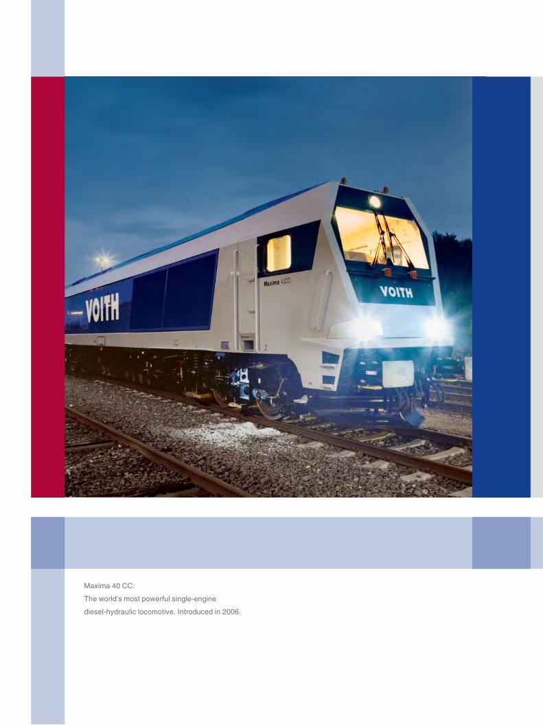
Maxima 40 CC:
The world‘s most powerful single-engine
diesel-hydraulic locomotive. Introduced in 2006.
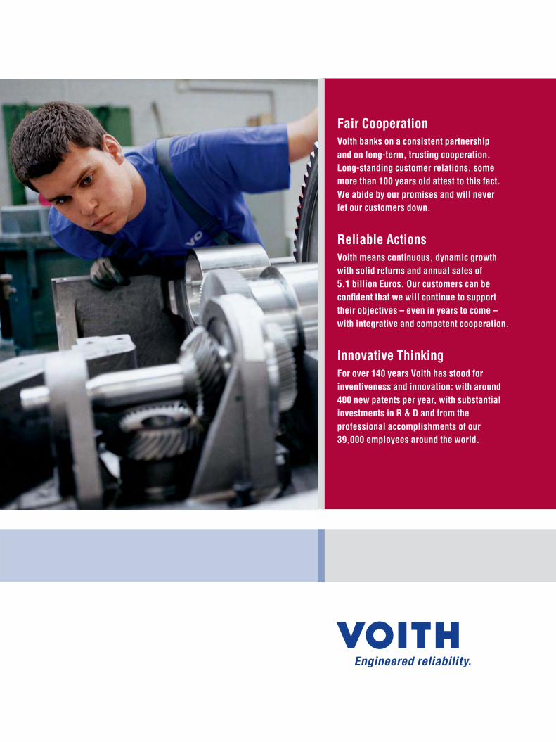
Fair Cooperation
Voith banks on a consistent partnership
and on long-term, trusting cooperation.
Long-standing customer relations, some
more than 100 years old attest to this fact.
We abide by our promises and will never
let our customers down.
Reliable Actions
Voith means continuous, dynamic growth
with solid returns and annual sales of
5.1 billion Euros. Our customers can be
confi dent that we will continue to support
their objectives – even in years to come –
with integrative and competent cooperation.
Innovative Thinking
For over 140 years Voith has stood for
inventiveness and innovation: with around
400 new patents per year, with substantial
investments in R & D and from the
professional accomplishments of our
39,000 employees around the world.

5Voith Turbo I Variable-Speed Turbo Couplings I cr 104 en
Voith Variable-Speed Turbo Couplings
Developed for Reliability
Fields of applications, drives of:
Voith Turbo is the worldwide leading manufacturer of hydro dynamic
variable-speed drives. Continuous development keeps our products
at the latest state of technology.
Ongoing research, state-of-the-art test equipment and a compre-
hensive quality assurance system form the basis of the reliability
of Voith variable-speed couplings. Voith variable-speed turbo cou-
plings are renowned all over the world for numerous features and
customer benefits in the widest range of applications.
Power plants:
� Fans
� Pumps
Materials handling:
� Slurry pumps
� Belt conveyors
District heating plants:
� Circulating pumps
Chemical industry:
� Pumps, Fans
� Mixers, Centrifuges
Oil & gas industry:
� Pumps
� Compressors
Metallurgical industry:
� Blowers
� Descaling pumps
Water industry:
� Water supply and waste water
pumps
Voith Turbo I Variable-Speed Turbo Couplings I cr 104 en
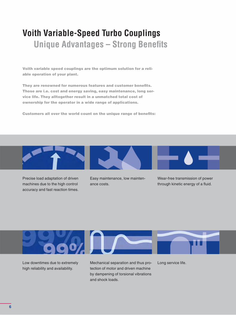
Voith Variable-Speed Turbo Couplings
Unique Advantages – Strong Benefi ts
Voith variable speed couplings are the optimum solution for a reli-
able operation of your plant.
They are renowned for numerous features and customer benefi ts.
Those are i.e. cost and energy saving, easy maintenance, long ser-
vice life. They alltogether result in a unmatched total cost of
ownership for the operator in a wide range of applications.
Customers all over the world count on the unique range of benefi ts:
Precise load adaptation of driven
machines due to the high control
accuracy and fast reaction times.
Easy maintenance, low mainten-
ance costs.
Long service life.
Wear-free transmission of power
through kinetic energy of a fl uid.
Mechanical separation and thus pro-
tection of motor and driven machine
by dampening of torsional vibrations
and shock loads.
Low downtimes due to extremely
high reliability and availability.
6
Voith Turbo I Variable-Speed Turbo Couplings I cr 104 en
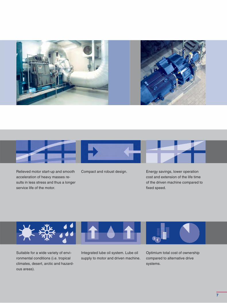
Relieved motor start-up and smooth
acceleration of heavy masses re-
sults in less stress and thus a longer
service life of the motor.
Compact and robust design. Energy savings, lower operation
cost and extension of the life time
of the driven machine compared to
fi xed speed.
Suitable for a wide variety of en vi-
ronmental conditions (i.e. tropical
climates, desert, arctic and hazard-
ous areas).
Integrated lube oil system. Lube oil
supply to motor and driven machine.
Optimium total cost of ownership
com pared to alternative drive
systems.
7
Voith Turbo I Variable-Speed Turbo Couplings I cr 104 en
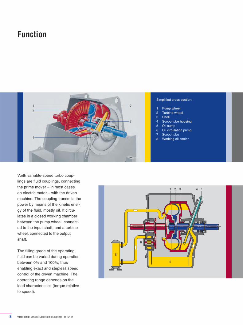
Simplified cross section:
1 Pump wheel2 Turbine wheel3 Shell4 Scoop tube housing5 Oil sump6 Oil circulation pump7 Scoop tube8 Working oil cooler
8
Function
Voith variable-speed turbo coup-
lings are fluid couplings, connecting
the prime mover – in most cases
an electric motor – with the driven
machine. The coupling transmits the
power by means of the kinetic ener-
gy of the fluid, mostly oil. It circu-
lates in a closed working chamber
bet ween the pump wheel, connect-
ed to the in put shaft, and a turbine
wheel, connected to the output
shaft.
The filling grade of the operating
fluid can be varied during operation
between 0% and 100%, thus
enabling exact and stepless speed
control of the driven machine. The
operating range depends on the
load characteristics (torque relative
to speed).
7
3
2
1
4
1 2 3 4 7
5
8
6
Voith Turbo I Variable-Speed Turbo Couplings I cr 104 en 9
Voith Variable-Speed Turbo Couplings
Torque Curves
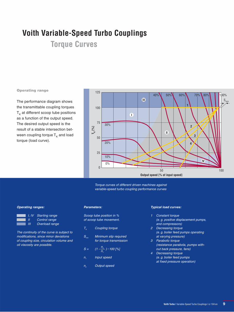
Operating range
The performance diagram shows
the transmittable coupling torques
TK at different scoop tube positions
as a function of the output speed.
The desired output speed is the
result of a stable intersection bet-
ween coup ling torque TK and load
torque (load curve).
Torque curves of different driven machines against variable-speed turbo coupling performance curves
Parameters:
Scoop tube position in % of scoop tube movement.
TK Coupling torque
Smin Minimum slip required for torque transmission
S = (1 - n2
n1
) • 100 [%]
n1 Input speed
n2 Output speed
Operating ranges:
I, IV Starting range II Control range III Overload range
The continuity of the curve is subject to modifications, since minor deviations of coupling size, circulation volume and oil viscosity are possible.
125
100
75
50
25
050 100
Smin
0%
10%
20%
30%
40% 50% 60% 70% 80% 100%
III
I
II
IV
1
2
3
4
TK [
%]
Output speed [% of input speed]
Typical load curves:
1 Constant torque (e. g. positive displacement pumps, and compressors)
2 Decreasing torque (e. g. boiler feed pumps operating at varying pressure)
3 Parabolic torque (resistance parabola, pumps with-out back pressure, fans)
4 Decreasing torque (e. g. boiler feed pumps at fixed pressure operation)
Voith Turbo I Variable-Speed Turbo Couplings I cr 104 en

Voith Turbo I Variable-Speed Turbo Couplings I cr 104 en10
Variable-Speed Turbo Couplings
Type SVTL
Coupling type SVTL has a self-sup-
porting design in a tunnel housing.
The rotating parts are supported in
the closed, oil-tight housing. Electric
motor and driven machine are con-
nected to the variable-speed turbo
coup ling via connecting couplings.
1 2 3 4 7
5
8
6
Simplified longitudinal section
1 Pump wheel
2 Turbine wheel
3 Shell
4 Scoop tube housing
5 Oil sump
6 Oil circulation pump
7 Scoop tube
8 Working oil cooler
The oil tank is integrated into the
housing, the oil pump is directly
driven by the input shaft. The shafts
are supported in antifriction bearings
which are lubricated by a mechani-
cally driven lube oil pump incorpo-
rated in the variable-speed coup ling.

Voith Turbo I Variable-Speed Turbo Couplings I cr 104 en 11
Variable-speed turbo coupling type SVTL in a boiler feed pump drive.
* With this design, oil tank extends into base, dimension B is therefore exceeded.
Size A B C Oil fi lling Weight
366-22 973 500 1,490 110 l 610 kg
422-22 973 500 1,490 110 l 630 kg
422-22-2,0 1,120 630 1,780 250 l 850 kg
487-21 973 500 1,490 110 l 570 kg
487-22 1,145 630 1,780 250 l 900 kg
487-12 1,255 800 1,780 500 l 1,200 kg
562-21 1,145 630 1,780 250 l 970 kg
562-12 1,255 800 1,780 500 l 1,260 kg
562-33 1,358 800 1,350 450 l 2,200 kg
562 HP 1,358 800 1,350 450 l 2,200 kg
650-21 1,310 750 2,000 300 l 1,200 kg
750-21-6,3 1,310 750 2,000 300 l 1,300 kg
750-22-12,8 1,469 725 1,400 400 l 1,750 kg*
866-22-12,8 1,469 725 1,400 400 l 1,800 kg*
Dimensions in mm.
A
B
C
Selection chart: Variable-speed turbo coupling type SVTL
5060
80100
200
300
400500600
8001000
2000
3000
40005000
7000
400 500 600 750 1000 1200 1500 1800 3000 3600
Input speed n1 [rpm]
Inp
ut
po
we
r ra
tin
g P
1 [
kW]
866
SVTL
22-
12,8
750
SVTL
21-
6,3
650
SVTL
21
562
SVTL
21
562
SVTL
12
487
SVTL
21
487
SVTL
22
422
SVTL
22
366
SVTL
22
562
SVTL
33
562
SVTL
HP
487
SVTL
12
422
SVTL
22-
2,0
750
SVTL
22-
12,8

Voith Turbo I Variable-Speed Turbo Couplings I cr 104 en
Simplified longitudinal section
1 Pump wheel
2 Turbine wheel
3 Shell
4 Scoop tube housing
5 Oil sump
6 Oil circulation pump
7 Scoop tube
8 Working oil cooler
12
Variable-Speed Turbo Couplings
Types SVNL, SVNLG
Coupling types SVNL and SVNLG
are of self-supporting design with a
horizontally split housing.
The rotating parts are located in the
completely closed, oil-tight housing.
Main motor and driven machine are
connected to the variable-speed tur-
bo coupling via connecting coup-
lings.
The oil tank is integrated into the
housing, a centrifugal oil pump (or,
with certain designs, a gear pump)
is used which is direct driven by the
input shaft.
With type SVNL, the main shafts
are supported by antifriction bear-
ings. The bear ings are force lubri-
cated using pressurized oil.
With type SVNLG, the main shafts
are supported by sleeve bearings.
The bearings are force lubricated by
pressur ized oil. For pre-lubrication
prior to start-up, an electric motor
driven auxiliary lubrication pump is
added.
1
8
8
556
6
47
117
2 3 1 2 3
4
Type SVNL Type SVNLG
Voith Turbo I Variable-Speed Turbo Couplings I cr 104 en 13
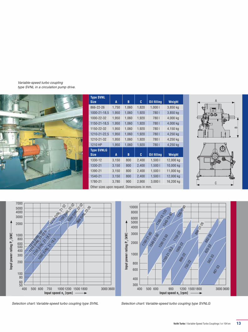
Variable-speed turbo coupling type SVNL in a circulation pump drive.
Type SVNL
Size A B C Oil fi lling Weight
866-22-26 1,750 1,060 1,820 1,000 l 3,850 kg
1000-21-18,5 1,950 1,060 1,920 780 l 3,850 kg
1000-22-32 1,950 1,060 1,920 780 l 4,000 kg
1150-21-18,5 1,950 1,060 1,920 780 l 4,000 kg
1150-22-32 1,950 1,060 1,920 780 l 4,150 kg
1210-21-22,5 1,950 1,060 1,920 780 l 4,250 kg
1210-21-32 1,950 1,060 1,920 780 l 4,250 kg
1210 HP 1,950 1,060 1,920 780 l 4,250 kg
Type SVNLG
Size A B C Oil fi lling Weight
1330-12 3,150 800 2,400 1,500 l 12,000 kg
1330-21 3,150 800 2,400 1,500 l 10,000 kg
1390-21 3,150 800 2,400 1,500 l 11,000 kg
1540-21 3,150 800 2,400 1,500 l 12,000 kg
1780-21 3,780 900 2,900 3,000 l 16,200 kg
Other sizes upon request. Dimensions in mm.
A
B
C
Selection chart: Variable-speed turbo coupling type SVNLG
5060
80100
200
300
400500600
8001000
2000
3000
40005000
7000
400 500 600 750 1000 1200 1500 1800 3000 3600
Input speed n1 [rpm]
Inp
ut
po
we
r ra
tin
g P
1 [
kW]
1150
SVN
L 21
-18,
512
10 S
VNL
21-3
2
1210
SVN
L HP
1210
SVN
L 21
-22,
5
1000
SVN
L 21
-18,
5
1150
SVN
L 22
-32
1000
SVN
L 22
-32
866
SVNL
22-
26
300
400
600
800
1000
2000
3000
4000
5000
8000
400 500 600 900 1200 15001800 3000 3600
Input speed n1 [rpm]
Inp
ut
po
we
r ra
tin
g P
1 [
kW]
1780
-21-
80
Selection chart: Variable-speed turbo coupling type SVNL
6000
10000
1780
-12-
120
1540
-21-
50
1540
-12-
80
1330
-12-
80
1330
-12-
5011
50-2
1-18
,5
487-
33
562-
33
620-
3368
2-33
750-
22
866-
22
866-
22-2
6
1000
-22
1150
-22

Voith Turbo I Variable-Speed Turbo Couplings I cr 104 en14
Variable-Speed Turbo Couplings
Type SVL
Coupling type SVL has a self-sup-
porting design with high power den-
sity. Input and output shafts are
supported separately in a cast iron
housing. Main motor and driven
machine are connected to the vari-
able-speed turbo coupling via con-
necting couplings.
1 2 3
4
8
10
7
9
56
11
The oil sump is flanged to the hous-
ing. The coupling has two oil circuits:
a working oil and a lubricating oil
circuit.
Both circuits are with mechanically
driven pumps. A flow control valve
adjusts the working oil flow to save
energy. The shafts are supported in
sleeve bearings which are force
lubricated using pres surized oil.
Simplified longitudinal section
1 Pump wheel
2 Turbine wheel
3 Shell
4 Coupling housing
5 Oil sump
6 Oil circulation pump
7 Scoop tube
8 Flow control valve
9 Auxiliary lubricating pump
10 Working oil cooler
11 Lube oil cooler
Voith Turbo I Variable-Speed Turbo Couplings I cr 104 en 15
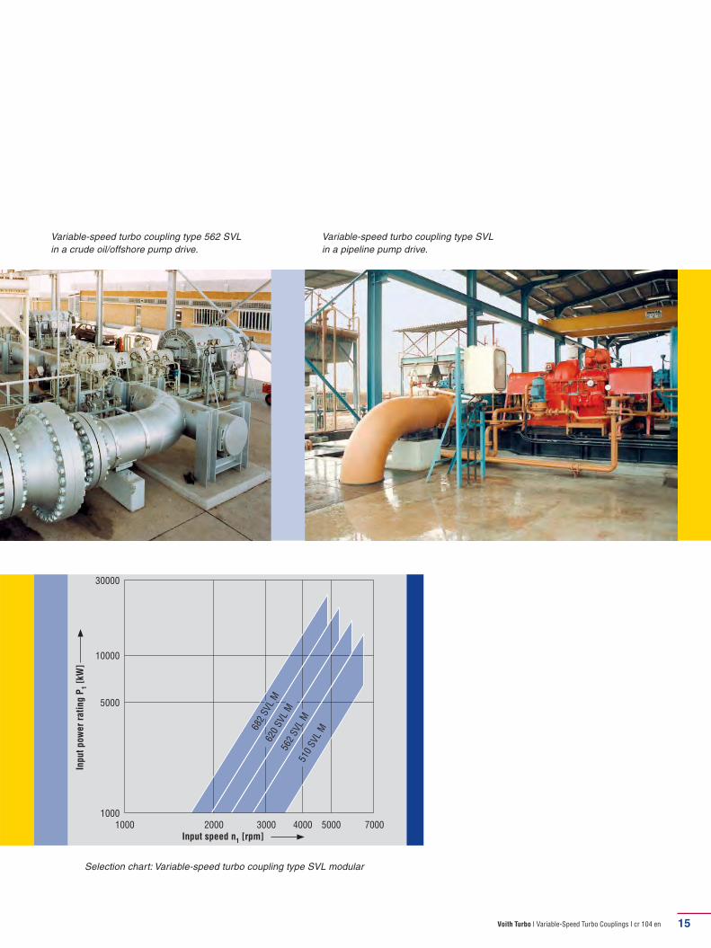
Variable-speed turbo coupling type 562 SVL in a crude oil/offshore pump drive.
Variable-speed turbo coupling type SVL in a pipeline pump drive.
Selection chart: Variable-speed turbo coupling type SVL modular
1000
30000
1000 2000 7000
Input speed n1 [rpm]
Inp
ut
po
we
r ra
tin
g P
1 [
kW]
682
SVL
M62
0 SVL
M56
2 SVL
M51
0 SVL
M
3000 4000 5000
10000
5000
Voith Turbo I Variable-Speed Turbo Couplings I cr 104 en16
Variable-Speed Turbo Couplings
Type SVTW
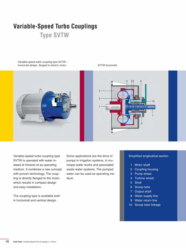
Variable-speed turbo coupling type
SVTW is operated with water in-
stead of mineral oil as operating
medium. It combines a new concept
with proven technology. The coup-
ling is directly flanged to the motor
which results in compact design
and easy installation.
The coupling type is available both
in horizontal and vertical design.
Simplified longitudinal section
1 Motor shaft
2 Coupling housing
3 Pump wheel
4 Turbine wheel
5 Shell
6 Scoop tube
7 Output shaft
8 Water supply line
9 Water return line
10 Scoop tube linkage
4 56
7
1
9
3
2
10
8
Variable-speed water coupling type SVTW – horizontal design, flanged to electric motor. SVTW horizontal.
Some applications are the drive of
pumps in irrigation systems, in mu-
nicipal water works and associated
waste water systems. The pumped
water can be used as operating me-
dium.

Voith Turbo I Variable-Speed Turbo Couplings I cr 104 en 17
Electric motor (P = 600 kW, n = 990 rpm) with vertical water coupling type 866 SVTW as drive of a drinking water pump in a German waterworks.
Size A B C D Weight
562 577 170 747 850 700 kg
650 738 170 930 960 847 kg
750 816 170 1,040 1,120 1,267 kg
866 1,011 210 1,273 1,350 2,040 kg
1000 1,133 250 1,415 1,500 2,990 kg
1150 vert. 1,254 250 1,586 1,720 4,450 kg
1390 vert. 1,522 300 1,894 2,065 6,750 kg
Dimensions in mm.
D
B
A
C
Selection chart: Variable-speed turbo coupling type SVTW
4500
400 600 750 900 1800
Input speed n1 [rpm]
Inp
ut
po
we
r ra
tin
g P
1 [
kW]
1390
ver
t.
3500
2500
1500
1000
500
1200 1500
1150
ver
t.10
00
866
750
650
562
100

Voith Turbo I Variable-Speed Turbo Couplings I cr 104 en18
Variable-Speed Turbo Couplings
Types SVNL vert., SVNK vert.
Type SVNL vert. Type SVNK vert.
Coupling type SVNL vert. is self-
supported and has a vertical de-
sign. The rotating parts are fully
supported in the housing.
Coupling type SVNK vert. is partly
self-supported and has also been
designed for vertical applications.
The coupling is supported by the
main motor shaft on the input side;
on the output side, a bearing has
been incorporated into the scoop
tube housing.
The housing of both types can be
adapted to the flange of the driven
machine. The oil supply is ensured
by a separate oil supply system.
Depending on the size, designs with
both antifriction and sleeve bearings
are available.
1
2
3
4
7
56
1
2
3
4
7
56
88
Simplified longitudinal section
1 Pump wheel
2 Turbine wheel
3 Shell
4 Scoop tube housing
5 Oil sump
6 Oil circulation pump
7 Scoop tube
8 Working oil cooler

Voith Turbo I Variable-Speed Turbo Couplings I cr 104 en
Selection chart: Variable-speed turbo coupling type SVNL vert.
200
5000
400 600 4000
Input speed n1 [rpm]
Inp
ut
po
we
r ra
tin
g P
1 [
kW]
1150
-22
4000
3000
2000
1000
500
300
2000 3000
19
Variable-speed turbo coupling type SVNL vert. in a waste water pump drive.
Size A B Cmin.*
487 945 775 680
562 1,250 1,030 790
650 1,250 1,030 890
750 1,614 1,305 1,050
866 1,614 1,305 1,180
1000 2,046 1,656 1,360
1150 2,046 1,656 1,560
Type SVNL vert. dimensions in mm.
Type SVNK vert. dimensions upon
request.
* customized to suit motor or driven
machine.
800 1200
1000
-22
866-
2275
0
650
562
487
366
316
C
B
A

Voith Turbo I Variable-Speed Turbo Couplings I cr 104 en
Integration of Voith Variable-Speed Turbo Coupling
into a Control Circuit
Position control circuit
Components:
� Scoop tube actuator including position controller for
continuous control operation
Process control circuit
Components:
� Process controller
� Scoop tube actuator including position control for
continuous control operation
If the speed is to be used as a pro cess value or if it is to
be displayed or to be incorporated, a speed mea suring
device is provided.
Similar to the speed, a process value (e. g. pressure,
flow, etc.) can be incorporated into a control cir cuit.
Then this process value is used as set value.
Variable-speed turbo couplings serve to control the speed of
driven machines. In many cases, the couplings are integrated
into an automatic process.
Position control circuit Process control circuit
MotorDriven
machineMotor
Driven
machine
Scoop tube
position controller
Actuator Actuator
Actual value scoop
tube position
4 – 20 mA
Set value
scoop tube position
4 – 20 mA
Actual value scoop
tube position
Set value scoop
tube position
Actual proces
value
4 – 20 mA
Set proces
value
4 – 20 mA
Speed
indicator
Process controller
Speed
measurement
device
Scoop tube
position controller
Pole wheel
with pick-up
20
Voith Turbo I Variable-Speed Turbo Couplings I cr 104 en
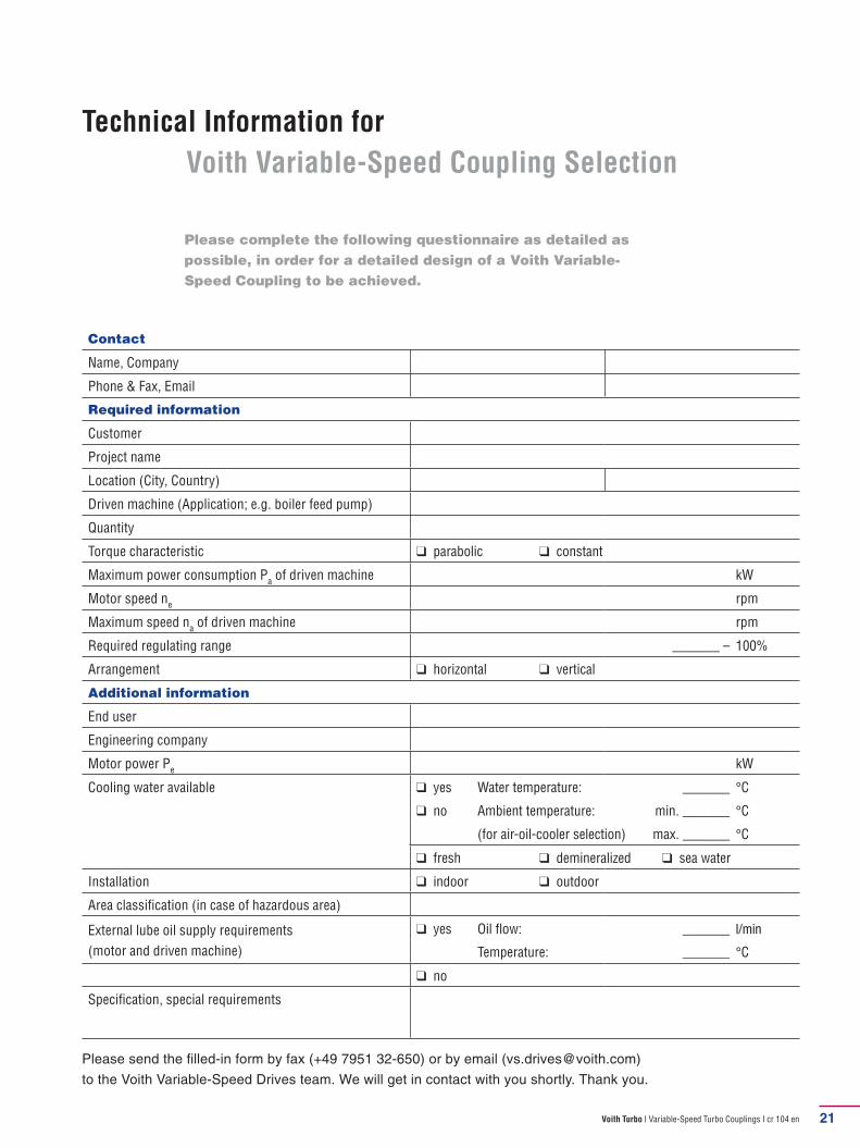
Technical Information for
Voith Variable-Speed Coupling Selection
21
Please complete the following questionnaire as detailed as possible, in order for a detailed design of a Voith Variable-Speed Coupling to be achieved.
Required information
Customer
Project name
Location (City, Country)
Driven machine (Application; e.g. boiler feed pump)
Quantity
Torque characteristic ❑ parabolic ❑ constant
Maximum power consumption Pa of driven machine kW
Motor speed ne
rpm
Maximum speed na of driven machine rpm
Required regulating range _______ – 100%
Arrangement ❑ horizontal ❑ vertical
Additional information
End user
Engineering company
Motor power Pe
kW
Cooling water available ❑ yes Water temperature: _______ °C
❑ no Ambient temperature: min. _______ °C
(for air-oil-cooler selection) max. _______ °C
❑ fresh ❑ demineralized ❑ sea water
Installation ❑ indoor ❑ outdoor
Area classifi cation (in case of hazardous area)
External lube oil supply requirements
(motor and driven machine)
❑ yes Oil flow: _______ l/min
Temperature: _______ °C
❑ no
Specifi cation, special requirements
Please send the fi lled-in form by fax (+49 7951 32-650) or by email ([email protected])
to the Voith Variable-Speed Drives team. We will get in contact with you shortly. Thank you.
Contact
Name, Company
Phone & Fax, Email 37,109 mm

Voith Turbo I Variable-Speed Turbo Couplings I cr 104 en
cr10
4en,
01.
2010
, 3.0
00, a
ik / W
A. D
imen
sion
s an
d ill
ustr
atio
ns w
ithou
t obl
igat
ion.
Sub
ject
to m
odifi
catio
ns.
Voith Turbo GmbH & Co. KG
Variable-Speed Drives
Voithstr. 1
74564 Crailsheim, Germany
Tel. +49-7951 32-0
Fax +49-7951 32-650
www.voithturbo.com / variable-speed