Embed Size (px)
Citation preview
ACTA TEHNICA CORVINIENSIS – Bulletin of Engineering Tome VII [2014] Fascicule 2 [April – June]
ISSN: 2067 – 3809
© copyright Faculty of Engineering - Hunedoara, University POLITEHNICA Timisoara
1. Eleonora DESNICA, 2. Danilo MIKIĆ
VARIOUS APPROACHES TO KINEMATIC ANALYSIS IN THE PROCESS OF DESIGN
OF PISTON MECHANISMS
1. University of Novi Sad, Technical Faculty ,,Mihajlo Pupin”, Zrenjanin, SERBIA
2. Technical School, Gornji Milanovac, SERBIA
Abstract: The purpose of this paper is to make an analysis of a system of piston mechanism and of its kinematic analysis on the one hand, and modeling and computer-aided design on the other hand. The paper uses kinematic analysis of a mechanism which is made in three methods – analytical, graphic and computer-aided which can also be successfully used in teaching engineers of technical sciences in higher education. Modern computer-aided methods are supported by a special software for analysis of treatment which can simulate not only movement of the mechanism, but it can also determine the position, velocity, acceleration, forces, moments and other parameters in every moment of time; however, control and application of mechanical laws are necessary. Some basic approaches, advantages and disadvantages of presented solutions are described. Keywords: piston mechanism, kinematic analysis, computer aided solution, piston velocity INTRODUCTION A piston mechanism is a kinematic chain which includes three components: crank, connecting rod and crosshead with a slipper whose purpose is to convert straight line motion to rotary motion and vice versa. The use of this mechanism is frequent especially in vehicles with internal combustion engines. A crankshaft, a piston, connecting rod and a cylinder (figures 1, 2 and 3) are parts of piston mechanism. Rotary motion of the crank is transferred to other systems of a vehicle via other parts of the engine, thus ensuring the geometric, kinematic and dynamic accuracy of the vehicle. It is a well known fact that there is a high degree of disturbance of the work of the crankshaft and the connecting rod. To identify these problems it is necessary to completely examine all parts of the mechanism to avoid high price of repair and maintenance, especially of the cylinder and the piston. The results of some researches show that the cause of damages in these parts lies in the “number of shifts of transmission during a drive, particularly when switching to the lower gear“. [1], [13] The mechanism has to convert straight line oscillating motion of the piston to a rotary motion of the crankshaft. This enables the work performed
by releasing of heat from the fuel in the piston crown to be transferred as turning moment to the crankshaft. [5], [6]
Figure 1. Piston mechanism:
1- piston , 2- connecting rod, 3- crankshaft
Figure 2. Parts of piston
ACTA TEHNICA CORVINIENSIS Fascicule 2 [April – June] – Bulletin of Engineering Tome VII [2014]
| 64 |
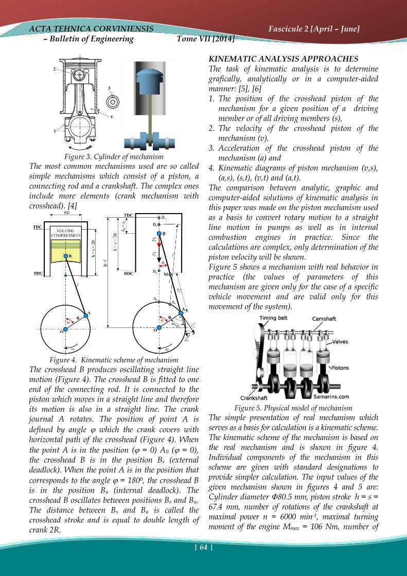
Figure 3. Cylinder of mechanism
The most common mechanisms used are so called simple mechanisms which consist of a piston, a connecting rod and a crankshaft. The complex ones include more elements (crank mechanism with crosshead). [4]
Figure 4. Kinematic scheme of mechanism
The crosshead B produces oscillating straight line motion (Figure 4). The crosshead B is fitted to one end of the connecting rod. It is connected to the piston which moves in a straight line and therefore its motion is also in a straight line. The crank journal A rotates. The position of point A is defined by angle ϕ which the crank covers with horizontal path of the crosshead (Figure 4). When the point A is in the position (ϕ = 0) A0 (ϕ = 0), the crosshead B is in the position Bs (external deadlock). When the point A is in the position that corresponds to the angle ϕ = 1800, the crosshead B is in the position Bu (internal deadlock). The crosshead B oscillates between positions Bs and Bu. The distance between Bs and Bu is called the crosshead stroke and is equal to double length of crank 2R.
KINEMATIC ANALYSIS APPROACHES The task of kinematic analysis is to determine grafically, analytically or in a computer-aided manner: [5], [6] 1. The position of the crosshead piston of the
mechanism for a given position of a driving member or of all driving members (s),
2. The velocity of the crosshead piston of the mechanism (v),
3. Acceleration of the crosshead piston of the mechanism (a) and
4. Kinematic diagrams of piston mechanism (v,s), (a,s), (s,t), (v,t) and (a,t).
The comparison between analytic, graphic and computer-aided solutions of kinematic analysis in this paper was made on the piston mechanism used as a basis to convert rotary motion to a straight line motion in pumps as well as in internal combustion engines in practice. Since the calculations are complex, only determination of the piston velocity will be shown. Figure 5 shows a mechanism with real behavior in practice (the values of parameters of this mechanism are given only for the case of a specific vehicle movement and are valid only for this movement of the system).
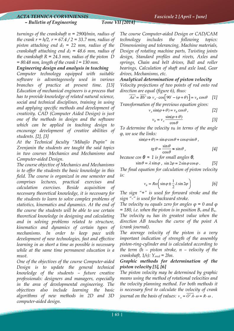
Figure 5. Physical model of mechanism
The simple presentation of real mechanism which serves as a basis for calculation is a kinematic scheme. The kinematic scheme of the mechanism is based on the real mechanism and is shown in figure 4. Individual components of the mechanism in this scheme are given with standard designations to provide simpler calculation. The input values of the given mechanism shown in figures 4 and 5 are: Cylinder diameter Φ80.5 mm, piston stroke h = s = 67.4 mm, number of rotations of the crankshaft at maximal power n = 6000 min-1, maximal turning moment of the engine Mmax = 106 Nm, number of
ACTA TEHNICA CORVINIENSIS Fascicule 2 [April – June] – Bulletin of Engineering Tome VII [2014]
| 65 |
turnings of the crankshaft n = 2900/min, radius of the crank r = h/2, r = 67.4 / 2 = 33.7 mm, radius of piston attaching end d1 = 22 mm, radius of the crankshaft attaching end d2 = 48.6 mm, radius of the crankshaft R = 24.3 mm, radius of the piston D = 80.48 mm, length of the crank l = 130 mm. Engineering design and analysis in teaching Computer technology equipped with suitable software is advantageously used in various branches of practice at present time. [13] Education of mechanical engineers is a process that has to provide knowledge of related natural science, social and technical disciplines, training in using and applying specific methods and development of creativity. CAD (Computer Aided Design) is just one of the methods in design and the software which can be applied in teaching design to encourage development of creative abilities of students. [2], [3] At the Technical faculty “Mihajlo Pupin” in Zrenjanin the students are taught the said topics in two courses Mechanics and Mechanisms and Computer-aided Design. The course objective of Mechanics and Mechanisms is to offer the students the basic knowledge in this field. The course is organized in one semester and comprises lectures, practical exercises and calculation exercises. Beside acquisition of necessary theoretical knowledge, it is necessary for the students to learn to solve complex problems of statistics, kinematics and dynamics. At the end of the course the students will be able to use certain theoretical knowledge in designing and calculating and in solving problems related to structure, kinematics and dynamics of certain types of mechanisms. In order to keep pace with development of new technologies, fast and effective learning in as short a time as possible is necessary while at the same time permanent education is a must. One of the objectives of the course Computer-aided Design is to update the general technical knowledge of the students – future creative professionals: designers and managers, especially in the area of developmental engineering. The objectives also include learning the basic algorithms of new methods in 2D and 3D computer-aided design.
The course Computer-aided Design or CAD/CAM technology includes the following topics: Dimensioning and tolerancing, Machine materials, Design of rotating machine parts, Twisting joints design, Standard profiles and rivets, Axles and springs, Chain and belt drives, Ball and roller bearings, Calculation of shaft and axle load, Gear drives, Mechanisms, etc. Analytical determination of piston velocity Velocity projections of two points of rod onto rod direction are equal (figure 6), thus:
' ' cos 90 ( ) cosA BAa Bb v vϕ θ θo⎡ ⎤= ⇒ ⋅ − + =⎣ ⎦ [1] Transformation of the previous equation gives:
sin( ) cosA Bv vϕ θ θ+ = , [2] sin( )cosB Av v ϕ θ
θ+
= [3]
To determine the velocity υB in terms of the angle φ, we use the links:
sin( ) sin cos cos sinϕ θ ϕ θ ϕ θ+ = + , sin sincos
tg θθ θ
θ= ≈ , [4]
because cos θ ≈ 1 is for small angles θ, sin sinθ λ ϕ= , sin 2 2sin cosϕ ϕ ϕ= . [5]
The final equation for calculation of piston velocity is:
1sin sin 22Bv Rω ϕ λ ϕ⎛ ⎞= ±⎜ ⎟
⎝ ⎠ [6]
The sign “+” is used for forward stroke and the sign “-“ is used for backward stroke. The velocity υB equals zero for angles φ = 0 and φ = 180, i.e. when the piston is in position Bs and Bu. The velocity υB has its greatest value when the direction AB touches the curve of the point A (crank journal). The average velocity of the piston is a very important indication of strength of the assembly piston-ring-cylinder and is calculated according to the term (h – piston stroke, n – velocity of the crankshaft, 1/s): Υsred = 2hn. Graphic methods for determination of the piston velocity [5], [6] The piston velocity may be determined by graphic means using the method of rotational velocities and the velocity planning method. For both methods it is necessary first to calculate the velocity of crank journal on the basis of values: 'av O A Rω ω= ⋅ = ⋅ .
ACTA TEHNICA CORVINIENSIS Fascicule 2 [April – June] – Bulletin of Engineering Tome VII [2014]
| 66 |
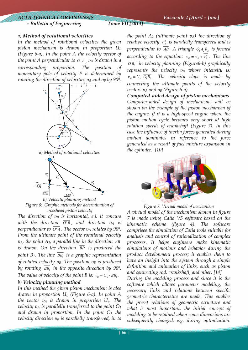
a) Method of rotational velocities In the method of rotational velocities the given piston mechanism is drawn in proportion UL (Figure 6-a). In the point A the velocity vector of the point A perpendicular to 'O A , υA is drawn in a corresponding proportion. The position of momentary pole of velocity P is determined by rotating the direction of velocities υA and υB by 900.
a) Method of rotational velocities
b) Velocity planning method
Figure 6: Graphic methods for determination of crosshead piston velocity
The direction of υB is horizontal, e.i. it concurs with the direction 'O B , and direction υA is perpendicular to 'O A . The vector υA rotates by 900. From the ultimate point of the rotational velocity υA, the point A1, a parallel line in the direction AB is drawn. On the direction BP is produced the point B1. The line 1BB is a graphic representation of rotated velocity υB. The position υB is produced by rotating 1BB in the opposite direction by 900. The value of velocity of the point B is: 1B vv U BB= ⋅ . b) Velocity planning method In this method the given piston mechanism is also drawn in proportion UL (Figure 6-a). In point A the vector υA is drawn in proportion Uυ. The velocity υA is parallelly transferred to the point O1 and drawn in proportion. In the point O1 the velocity direction υB is parallelly transferred, in to
the point A2 (ultimate point υA) the direction of relative velocity A
Bv is parallelly transferred and is perpendicular to AB . A triangle 1 2 2O A B is formed according to the equation: A
B A Bv v v= + . The line 1 2O B in velocity planning (Figure6-b) graphically
represents the velocity υB whose intensity is: 1 2B vv U O B= ⋅ . The velocity slope is made by
connecting the ultimate points of the velocity vectors υA and υB (Figure 6-a). Computed-aided design of piston mechanisms Computer-aided design of mechanisms will be shown on the example of the piston mechanism of the engine, if it is a high-speed engine where the piston motion cycle becomes very short at high rotation speeds of crankshaft (Figure 7). In this case the influence of inertia forces generated during motion dominates in reference to the force generated as a result of fuel mixture expansion in the cylinder. [10]
Figure 7. Virtual model of mechanism
A virtual model of the mechanism shown in figure 7 is made using Catia V5 software based on the kinematic scheme (figure 4). The software comprises the simulation of Catia tools suitable for analysis and control of rationalization of complex processes. It helps engineers make kinematic simulations of motions and behavior during the product development process; it enables them to have an insight into the system through a simple definition and animation of links, such as piston and connecting rod, crankshaft, and other. [14] During the modeling process and since it is the software which allows parameter modeling, the necessary links and relations between specific geometric characteristics are made. This enables the preset relations of geometric structure and what is most important, the initial concept of modeling to be retained when some dimensions are subsequently changed, e.g. during optimization.
ACTA TEHNICA CORVINIENSIS Fascicule 2 [April – June] – Bulletin of Engineering Tome VII [2014]
| 67 |
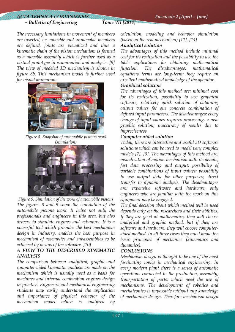
The necessary limitations in movement of members are inserted, i.e. movable and unmovable members are defined, joints are visualized and thus a kinematic chain of the piston mechanism is formed as a movable assembly which is further used as a virtual prototype in examination and analysis. [9] The view of modeled 3D mechanism is shown in figure 8b. This mechanism model is further used for visual animations.
Figure 8. Snapshot of automobile pistons work
(simulation)
Figure 9. Simulation of the work of automobile pistons
The figures 8 and 9 show the simulation of the automobile pistons work. It helps not only the professionals and engineers in this area, but also drivers to simulate engines and actuators. It is a powerful tool which provides the best mechanism design in industry, enables the best purpose in mechanism of assemblies and subassemblies to be achieved by means of the software. [10] A VIEW TO THE DESCRIBED KINEMATIC ANALYSIS The comparison between analytical, graphic and computer-aided kinematic analysis are made on the mechanism which is usually used as a basis for machines and internal combustion engines design in practice. Engineers and mechanical engineering students may easily understand the application and importance of physical behavior of the mechanism model which is analyzed by
calculation, modeling and behavior simulation (based on the real mechanism) [11], [14] Analytical solution The advantages of this method include minimal cost for its realization and the possibility to use the table applications for obtaining mathematical function. The disadvantages: mathematical equations terms are long-term; they require an excellent mathematical knowledge of the operator. Graphical solution The advantages of this method are: minimal cost for its realization, possibility to use graphical software, relatively quick solution of obtaining output values for one concrete combination of defined input parameters. The disadvantages: every change of input values requires processing, a new graphic solution; inaccuracy of results due to impreciseness. Computer aided solution Today, there are interactive and useful 3D software solutions which can be used to model very complex models [7], [8]. The advantages of this method are: visualization of motion mechanism with its details; fast data processing and output; possibility of variable combinations of input values; possibility to use output data for other purposes; direct transfer to dynamic analysis. The disadvantages are: expensive software and hardware, only engineers who are familiar with the work on this equipment may be engaged. The final decision about which method will be used depends only on the researchers and their abilities. If they are good at mathematics, they will choose analytical and graphic method, but if they use software and hardware, they will choose computer-aided method. In all three cases they must know the basic principles of mechanics (kinematics and dynamics). CONLUSIONS Mechanism design is thought to be one of the most fascinating topics in mechanical engineering. In every modern plant there is a series of automatic operations connected to the production, assembly, transportation of parts, which need the use of mechanisms. The development of robotics and mechatronics is impossible without any knowledge of mechanism design. Therefore mechanism design
ACTA TEHNICA CORVINIENSIS Fascicule 2 [April – June] – Bulletin of Engineering Tome VII [2014]
| 68 |
is of wider importance for everyday practice as well as for modern technology. Computer using in designing and constructing is not news any more, but inevitability. Introducing the computer technology in designing and constructing process changes a character of user’s work and changes his professional preparation. There are plenty of techniques of governing the application of corresponding program packages for the designing process. Designing with its requests includes needs for simulations of real conditions as well as analysis of interaction of models with the surroundings. The machine or mechanism design always starts with kinematics consideration. Kinematics is the study of geometry of motion, i.e. of relations between linked parts and their motion in relation to each other. Insufficient knowledge of kinematics may result in a design of a system with failures, with no optimal effect and/or with insufficient reliability. Very powerful personal computers are available today with software products which enable kinematic analysis and synthesis that were not easily, efficiently and cheaply made before. Availability of such complex and expensive computers stimulate defining kinematic principles in design. It could be said that mechanisms, along with other disciplines, are an area which both a designer and a user of machines must know well. This gives them confidence in solving tasks, designing mechanisms or adjusting them to conditions of use, which will satisfy all necessary requirements. The prerequisite for this is certainly a good knowledge of modern software tools. REFERENCES [1.] Bilek, O., Lukovics, I., Finite Element Model of
Dynamics within Highspeed Grinding Process, Academic Journal of Manufacturing Engineering, pp. 6-11, 2009.
[2.] Desnica, E., Letić, D., Advancing machine elements teaching in technical fields at university level education, Journal „Machine design”, pp.45-48, 2007.
[3.] Desnica, E., Letić, D., Gligorić, R., Navalušić, S., The importance of improving education for successful performance of engineering tasks, International Symposium KOD 2012 - Machine and industrial design in mechanical engineering, pp. 91-96, 2012.
[4.] Eckhardt, Homer D., Kinematic design of machines and Mechanisms, McGraw-Hill Companies,, pp.11-24, 1998.
[5.] Gligorić, R., Mechanisms of agricultural machinery, Faculty of Agriculture, Novi Sad, 2005.
[6.] Husnjak, M., Mehanizmi, Teorija mehanizama, Zagreb, 2010.
[7.] Letić, D., Desnica, E., Engineering Graphics I and II, Technical faculty “Mihajlo Pupin”, Zrenjanin, 2011.
[8.] Mikić, D., Ašonja, A., Gligorić, R., Savin, L., Tomić, M., Dynamic Solving of Rotational Transformation Matrix Using the D’ALAMBER Principle, Journal TTEM, Vol.7, No.3, pp.1187-1195, 2012.
[9.] Mikić D., Desnica, E., Aleksandar, A., Adamović, Ž., Mechanical modeling of industrial machines, II International Conference – Industrial Engineering And Environmental Protection (IIZS 2012), Zrenjanin, october 2012.
[10.] Mikić, D., Modeliranje mašinskih elemenata i konstrukcija u obrazovanju primenom softverskog paketa Catia“, Internacionalna konferencija Tehnika i informatika u obrazovanju, str.552-559, 2010.
[11.] Monkova, K., Monka, P., Hloch, S., Valiček, J., Kinematic analysis of quick-return mechanism in three various approaches, Technical Gazette 18, 2(2011), pp. 295-299, 2011.
[12.] Novak-Marcincin, J., Computer modelling and simulation of automated manufacturing systems, Annals of Faculty Engineering Hunedoara – International Journal of Engineering, Tome XI, fascicule 2, pp.23-26, 2013.
[13.] Rao, J. S., Dukkipati, R. V., Mechanism and Machine Theory, New Age International Ltd. Publisher, pp. 22-71. 1992.
[14.] http://www.autopedija.com/index.php/2008112265/konfiguracije-motora.html
copyright ©
University “POLITEHNICA” Timisoara, Faculty of Engineering Hunedoara,
5, Revolutiei, 331128, Hunedoara, ROMANIA http://acta.fih.upt.ro