Embed Size (px)
Citation preview
Various New Wireless technologies and test Solutions
SeungSeung‐‐Chul ShinChul ShinApplication EngineerApplication EngineerAgilent TechnologiesAgilent Technologies
Page 1
Agenda
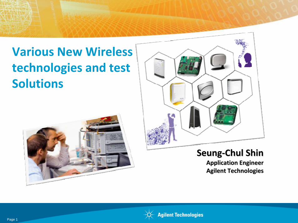
1. HSPA+, E-EDGE2. Battery drain test3. A-GPS4. DigiRF5. Femtocell
Page 2
Enabling Market Drivers
•Mobile music growing to $11B worldwide by 2011
•Mobile TV subscribers worldwide to exceed 460 Million by 2012•Mobile broadband computing is a tremendous opportunity; 70M unit opportunity worth some $50b in 2008
•Mobile workforce is growing – bandwidth & Speed to support enterprise applications necessary
•Most 3G operators currently have upgraded or plan to upgrade HSPA.
Page 3
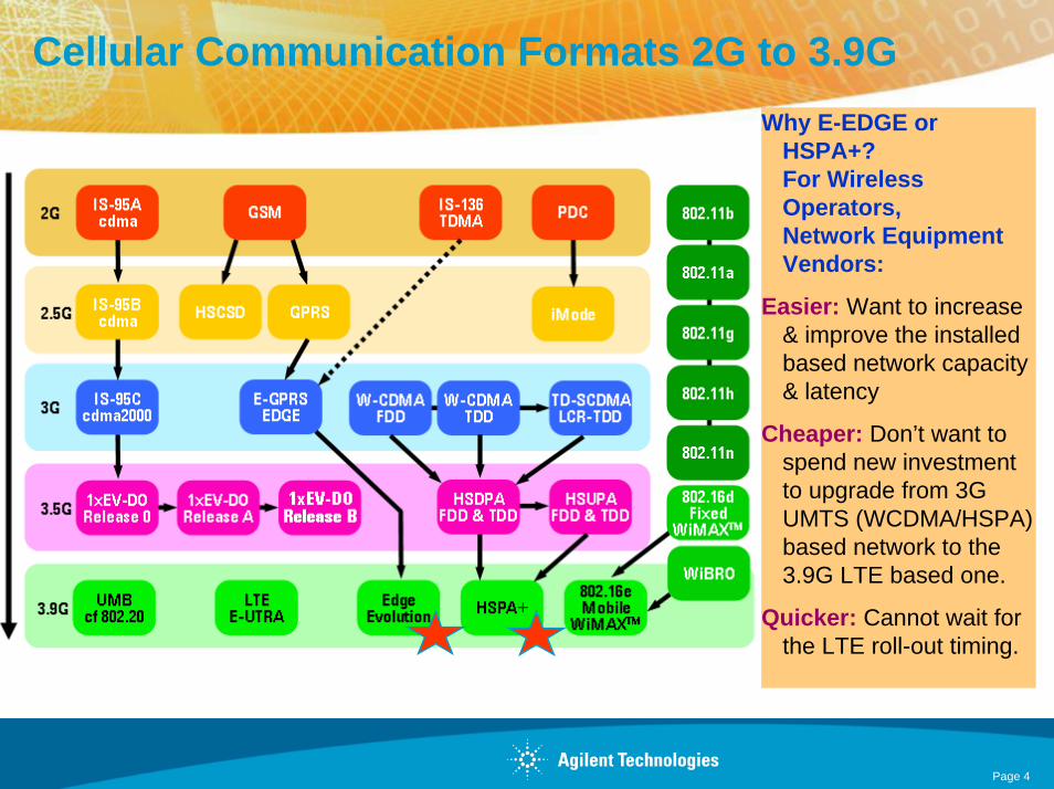
Cellular Communication Formats 2G to 3.9GWhy E-EDGE or
HSPA+? For Wireless Operators,Network Equipment Vendors:
Easier: Want to increase & improve the installed based network capacity & latency
Cheaper: Don’t want to spend new investment to upgrade from 3G UMTS (WCDMA/HSPA) based network to the 3.9G LTE based one.
Quicker: Cannot wait for the LTE roll-out timing.
Page 4
What’s “HSPA (High Speed Packet Access)”?Reminder of HSPA concepts
HSPA+
“HSPA” contains both “HSDPA” and “HSUPA”.
HSDPA: High Speed Downlink Packet Access
• Evolutional configuration for high rate packet data access for downlink.• Introduced as a part of 3GPP Release-5, overlaid on the 3GPP Release-99
(W-CDMA)• Applied the new “HS-” (or “hs-”) channels in PHY, TrCH, MAC layers.
(HS: High Speed (downlink))
HSUPA: High Speed Uplink Packet Access
• Evolutional configuration for high rate packet data access for uplink.• Introduced as a part of 3GPP Release-6, overlaid on the Release-99 (W-
CDMA) and Release-5 (HSDPA)• Applied “E-” (or “e-”) channels in PHY, TrCH, MAC layers.
(E: Enhanced (uplink))
Page 5

What’s “HSPA+ (High Speed Packet Access)”?Improvements to HSPA
HSPA+
HSPA+, (also known as: HSPA Evolution, Evolved HSPA, I-HSPA or Internet HSPA) is a wireless broadband standard defined in 3GPP release 7.HSPA+ aims to provide data rates up to 42 Mbit/s on the downlink and 22 Mbit/s on the uplink Uses MIMO technologies and higher order modulation to achieve these higher data rates.It also introduces an optional all-IP architecture for the network where base stations are directly connected to the internet. HSPA+ should not be confused with LTE, which uses a new air interface.
Page 6
HSDPA (DL), HSUPA (UL) vs. HSPA+ (DL, UL) Quick Comparison
HSPA+
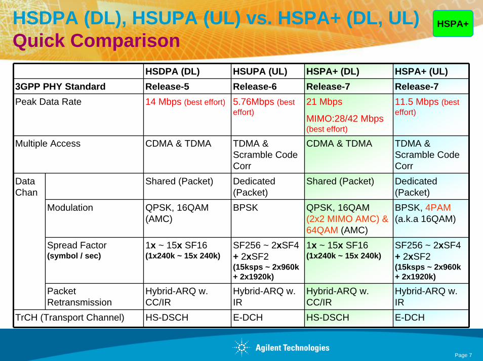
HSDPA (DL) HSUPA (UL) HSPA+ (DL) HSPA+ (UL)3GPP PHY Standard Release-5 Release-6 Release-7 Release-7Peak Data Rate 14 Mbps (best effort) 5.76Mbps (best
effort)21 Mbps
MIMO:28/42 Mbps (best effort)
11.5 Mbps (best effort)
Multiple Access CDMA & TDMA TDMA & Scramble Code Corr
CDMA & TDMA TDMA & Scramble Code Corr
Shared (Packet) Dedicated (Packet)
Shared (Packet) Dedicated (Packet)
Modulation QPSK, 16QAM (AMC)
BPSK QPSK, 16QAM (2x2 MIMO AMC) & 64QAM (AMC)
BPSK, 4PAM(a.k.a 16QAM)
Spread Factor(symbol / sec)
1x ~ 15x SF16(1x240k ~ 15x 240k)
SF256 ~ 2xSF4+ 2xSF2(15ksps ~ 2x960k + 2x1920k)
1x ~ 15x SF16(1x240k ~ 15x 240k)
SF256 ~ 2xSF4+ 2xSF2(15ksps ~ 2x960k + 2x1920k)
Data Chan
Packet Retransmission
Hybrid-ARQ w. CC/IR
Hybrid-ARQ w. IR
Hybrid-ARQ w. CC/IR
Hybrid-ARQ w. IR
TrCH (Transport Channel) HS-DSCH E-DCH HS-DSCH E-DCH
Page 7
HSPA+Transmitter TestingNew items to be aware of:
Modulation Analysis & Code Domain measurement
• Downlink Test Model 6 (HS-PDSCH in 64QAM)
• Downlink/Uplink Relative Code Domain Error (R-CDE)
• Uplink 4PAM-I/Q (like 16QAM)
Page 8

New “Test Model 6” for 64QAM HSPA+ testTS25.141 BTS Conformance Test: 6.1.1.4B Test Model 6
HSPA+
•Code set and locations are the same as the “Test Model 5 with 8 HS-PDSCH”, defined in 3GPP TS25.141 section 6.1.1.4A. The differences are:
• All 8 HS-PDSCH code channels are modulated with 64QAM
• Code power profile among HS-PDSCH and DPCH are slightly different.
•Test Model 6 is used for the new “RCDE”requirement, defined in 3GPP TS25.141 section 6.7.4.
Page 9

8960 HSPA+ Roadmap for LA
Available Now (as of May 2009)• 64QAM DL• Layer 2 MAC-ehs/e/hs signaling• Loopback to HSUPA or WCDMA• H-Set 8 with 64QAM• HSPA+ feature option on E1963A TA• HSPA+ DL in FDD test and RB test modes• HSPA+ DL IP data channel
For Future Consideration• 16QAM uplink with loopback• 16QAM Tx measurements
Page 10

Lets compare the battle for the mass car market to the cellular market. Quiz: Which is faster ?
Tata Nano $2,500
(EDGE Evolution <1Mbps)
Bugatti Veyron $1,500,000
(LTE ~300Mbps)
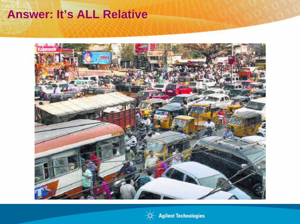
Answer: It’s ALL Relative
E-EDGEWhat’s “EDGE Evolution”?
EDGE = Enhanced Data rates for Global System for Mobile communications Evolution
EDGE Evolution = Enhanced Data rates for Global System for Mobile communications Evolution, Evolution
(also known as: E-EDGE (Evolved-EDGE), GERAN evolution)
• Standards working group uses the term REDHOT: Reduced symbolDuration, Higher Order modulation and Turbo codes
• Standards working group also uses the term HUGE: Higher Uplinkperformance for Geran Evolution
• Introduced as a part of 3GPP Rel-7
Page 13

E-EDGEWhat is Evolved EDGE?
Improvements to EDGE• Latencies are reduced by lowering the Transmission Time Interval by half (from 20 ms to 10 ms).
• Bit rates are increased and latencies down using dual carriers, higher symbol rate and higher-order modulation (16QAM and 32QAM as well as 8-PSK), and turbo codes to improve error correction.
• Signal quality is improved using dual antennas.
An EDGE Evolution terminal or network can support some of these improvements, or roll them out in stages.
Page 14
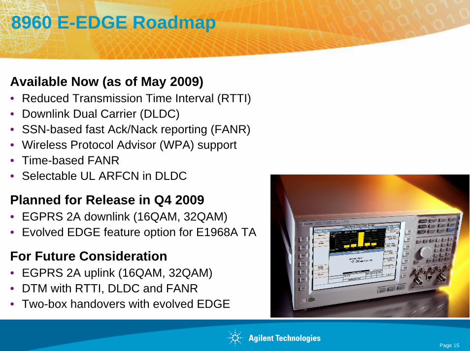
8960 E-EDGE Roadmap
Available Now (as of May 2009)• Reduced Transmission Time Interval (RTTI)• Downlink Dual Carrier (DLDC)• SSN-based fast Ack/Nack reporting (FANR)• Wireless Protocol Advisor (WPA) support• Time-based FANR• Selectable UL ARFCN in DLDC
Planned for Release in Q4 2009• EGPRS 2A downlink (16QAM, 32QAM)• Evolved EDGE feature option for E1968A TA
For Future Consideration• EGPRS 2A uplink (16QAM, 32QAM)• DTM with RTTI, DLDC and FANR• Two-box handovers with evolved EDGE
Page 15

Battery Life is #1 Problem for Smartphones
To fully optimize battery life must consider battery drain at all stages of development: RF HW design, integration, SW apps, validation
Existing test processes do not use realistic test scenarios to simulate device battery usage.
Must go beyond Talk Time testing to include more realistic testing for battery life
14565B Battery Drain software measures voltage and current characteristics now can add real-world stimulus with the 8960.
Only Agilent provides a battery drain test solution that provides “User Profile” stimulus to enable real-world battery drain test.
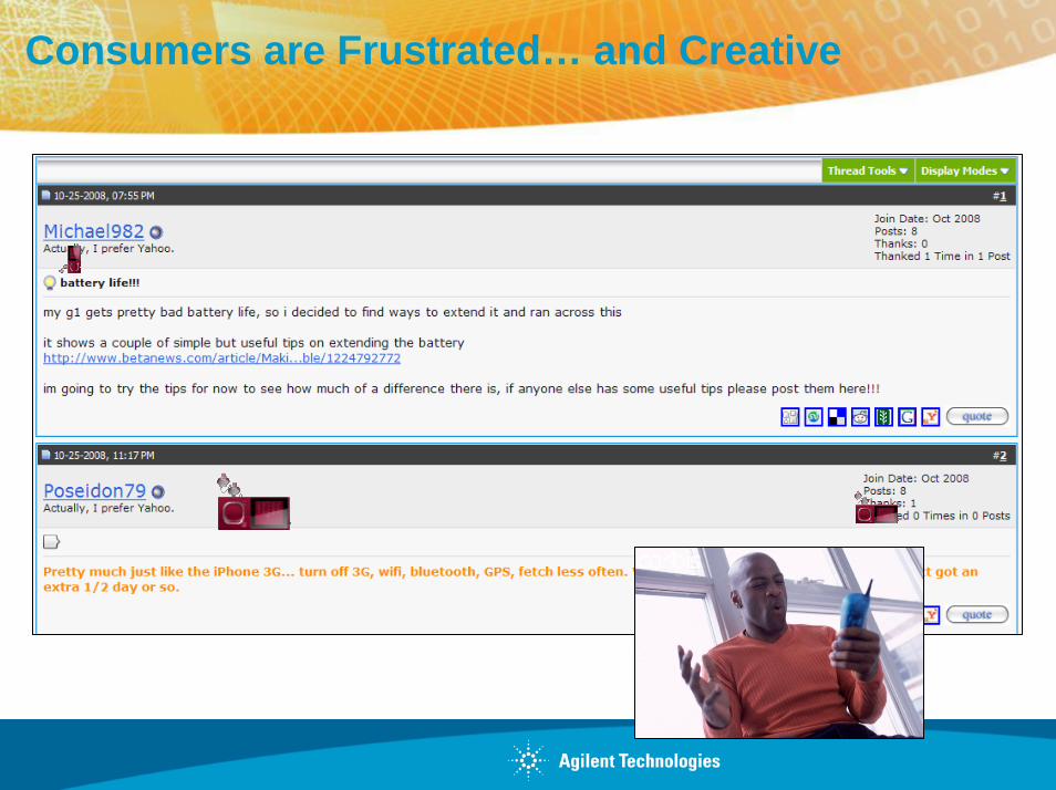
Consumers are Frustrated… and Creative
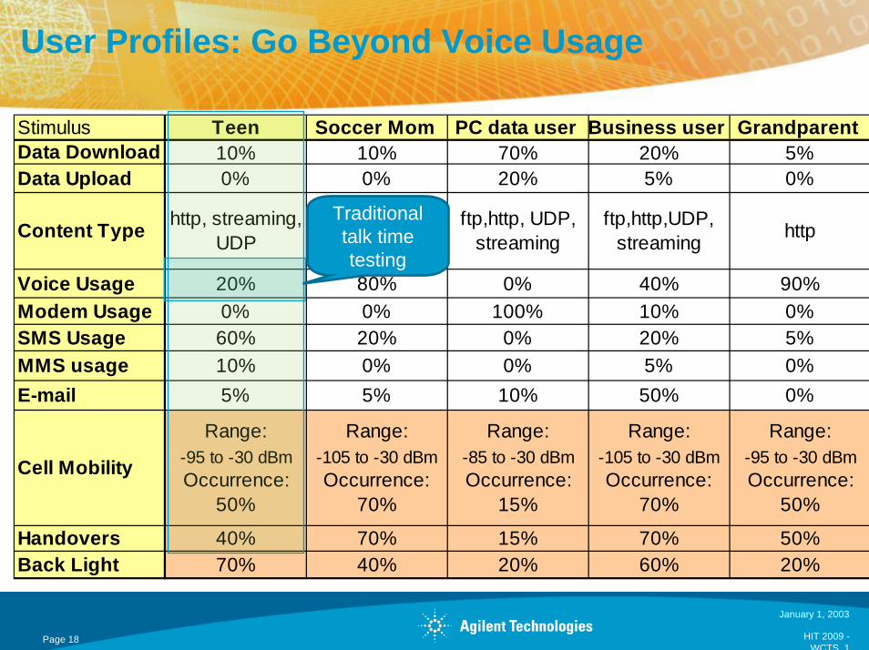
User Profiles: Go Beyond Voice Usage
Stimulus Teen Soccer Mom PC data user Business user Grandparent Data Download 10% 10% 70% 20% 5%Data Upload 0% 0% 20% 5% 0%
Content Type http, streaming, UDP http ftp,http, UDP,
streamingftp,http,UDP,
streaming http
Voice Usage 20% 80% 0% 40% 90%Modem Usage 0% 0% 100% 10% 0%SMS Usage 60% 20% 0% 20% 5%MMS usage 10% 0% 0% 5% 0%E-mail 5% 5% 10% 50% 0%
Cell Mobility
Range: -95 to -30 dBmOccurrence:
50%
Range:-105 to -30 dBmOccurrence:
70%
Range: -85 to -30 dBmOccurrence:
15%
Range:-105 to -30 dBmOccurrence:
70%
Range:-95 to -30 dBmOccurrence:
50%
Handovers 40% 70% 15% 70% 50%Back Light 70% 40% 20% 60% 20%
Traditional talk time testing
January 1, 2003
HIT 2009 -WCTS 1
Page 18
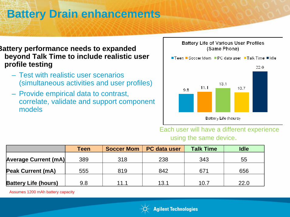
Battery Drain enhancements
Battery performance needs to expanded beyond Talk Time to include realistic user profile testing
– Test with realistic user scenarios (simultaneous activities and user profiles)
– Provide empirical data to contrast, correlate, validate and support component models
Each user will have a different experience using the same device.
Teen Soccer Mom PC data user Talk Time Idle
Average Current (mA) 389 318 238 343 55
Peak Current (mA) 555 819 842 671 656
Battery Life (hours) 9.8 11.1 13.1 10.7 22.0Assumes 1200 mAh battery capacity

Current Drain variations based on User Profiles
Data Modem User
Teen
Soccer Mom

Insightful Real World Battery Run-down Testing
+ +
--
ILOAD
ILOADRSHUN
T
VSHUNT (1 x VSHUNT)
VDROP = ZERO-- outout + out+ out
Zero-burden active shunt concept
DVM inDVM in
-- outout + out+ out
+ in+ in
-- inin
DUT batteryDUT batteryB+B+ BB--
Output set to 0 voltsOutput set to 0 volts
VVinin = = VVbatterybattery
Iload
Iload
battery voltage
maximum current
average current minimum current
Agilent 14565B software capturing the talk time battery run-down of a GSM handset :
• Characterize and validate DUT and its battery together• Determine Amp-Hours and Watt-Hours actually delivered• Verify low voltage shut-down termination
Agilent 66319B DC source output set to zero volts and connected in series becomes zero burden active shunt:
• Use actual DUT battery, real world results• No shunt V drop, DUT sees full battery voltage• DUT sees actual battery impedance only• DVM input logs actual battery run-down voltage
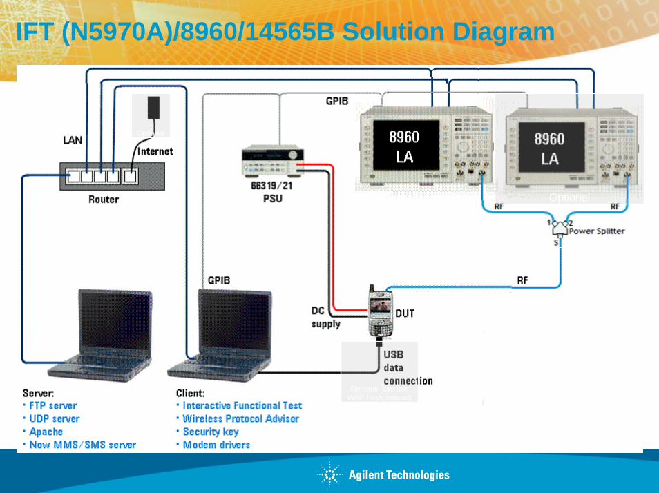
IFT (N5970A)/8960/14565B Solution Diagram
Optional
Optional (can use WAP Push instead)
Optional

W-CDMA/HSPA
What’s New with the 8960: Battery Drain
RRC state transitions: UE states defined for packet-switched data to provide high network capacity while optimizing user experience and device battery life
– Evaluate mobile transition behaviors between Idle, CELL_DCH, CELL_FACH, CELL_PCH, and URA_PCH
– Assess realistic battery life with different CELL_FACH timer scenariosWhat’s new May 2009:
– RRC state transitions with HSPA– Automatic RRC state transitions based on settable inactivity timers– FACH Measurement Occasions
Low battery consumption
Low data rates
URA_PCHCELL_PCH
CELL_DCH CELL_FACH
IDLEMost battery consumption
Highest data rates
Most Battery Consumption
Low battery consumption
Most battery consumption
No data transfer
Least battery consumption

Battery life tests
Current battery life tests do not take into account concurrent (or simultaneous) data-driven based activities
End-users are dissatisfied with device battery life
Wireless devices will continue to grow in complexity
Service Providers are changing their testing techniques
Use accurate “User profiles” for realistic prediction and validation of battery life of 3G mobile devices
Agilent is the only solution for real-world battery test– User profile testing is enabled by the 8960’s data test capabilities and
IFT automation
24 Group/Presentation TitleAgilent Restricted
Month ##, 200X

Position Location using pure GPS vs. A-GPS
A mobile phone can use GPS satellites to calculate its location…but• It takes a long time to find satellites (GPS time to fix up to 12.5 minutes)
• Accuracy is poor indoors/under cover
• It drains battery life
A-GPS (Assisted GPS) development was driven by U.S. FCC E911 requirement to quickly provide cell phone location to emergency call dispatchers. A-GPS provides the mobile with knowledge of the GPS satellites.
“assistance data” is provided by the base station to help the mobile find the GPS satellites more quickly.
The wireless device looks for the GPS satellites and
determines its location
A-GPS brings the Time to First Fix down to seconds vs. minutes
The wireless device then reports its location back to the base station
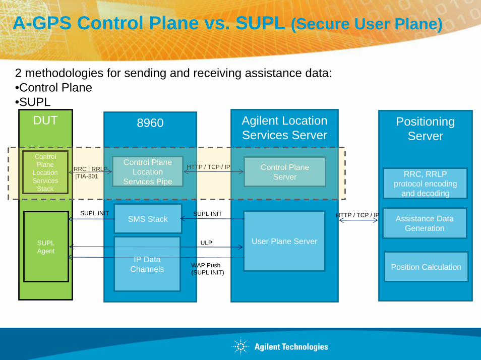
A-GPS Control Plane vs. SUPL (Secure User Plane)
DUT 8960
Control Plane
Location Services
Stack
SUPL Agent
Control Plane Location
Services Pipe
Agilent Location Services Server
Control Plane Server
User Plane Server
Positioning Server
RRC, RRLP protocol encoding
and decoding
Assistance Data Generation
Position Calculation
HTTP / TCP / IPSMS Stack
HTTP / TCP / IP
SUPL INITSUPL INIT
ULP
RRC | RRLP|TIA-801
WAP Push (SUPL INIT)
IP Data Channels
2 methodologies for sending and receiving assistance data: •Control Plane•SUPL
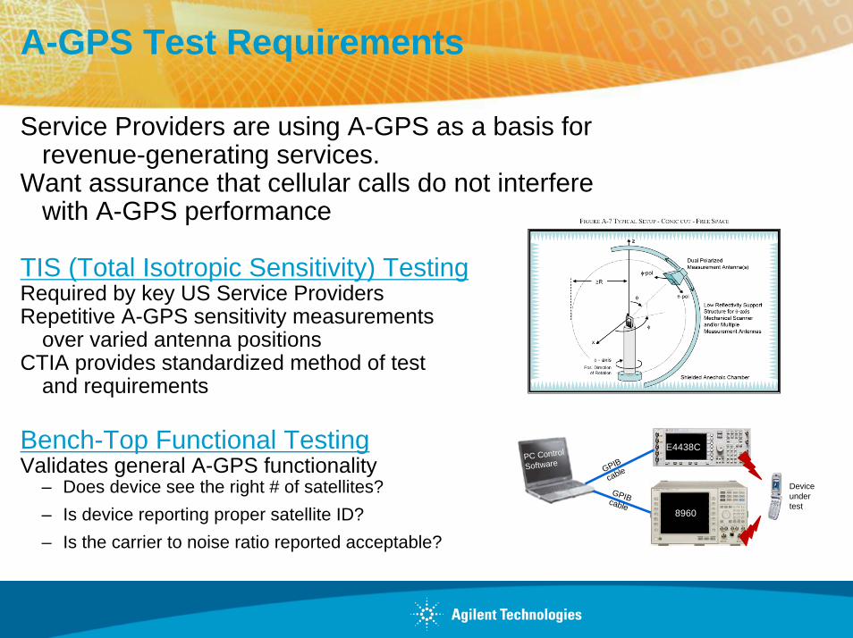
A-GPS Test Requirements
Service Providers are using A-GPS as a basis for revenue-generating services.
Want assurance that cellular calls do not interfere with A-GPS performance
TIS (Total Isotropic Sensitivity) TestingRequired by key US Service ProvidersRepetitive A-GPS sensitivity measurements
over varied antenna positionsCTIA provides standardized method of test
and requirements
Bench-Top Functional TestingValidates general A-GPS functionality
– Does device see the right # of satellites?– Is device reporting proper satellite ID?– Is the carrier to noise ratio reported acceptable?
PC Control
SoftwareGPIB
cable
GPIB cable8960
E4438C
Device under test

Agilent A-GPS Test Solution
Signal Simulation for Aerospace & Defense Applications
Agilent Restricted
Types of Assistance Data Messages Supported:
•2G A-GPS Testing: 8960 supports piping of RRLP assistance data message.
•3G A-GPS Testing: 8960 supports RRC assistance data message.
•No SUPL server support
Test results:
•GPS Time of Week (TOW)
•Number of Satellites
•Satellite Identification (ID) Number
•Time to First Fix (TTFF)
•Carrier to Noise Ratio (C/No)
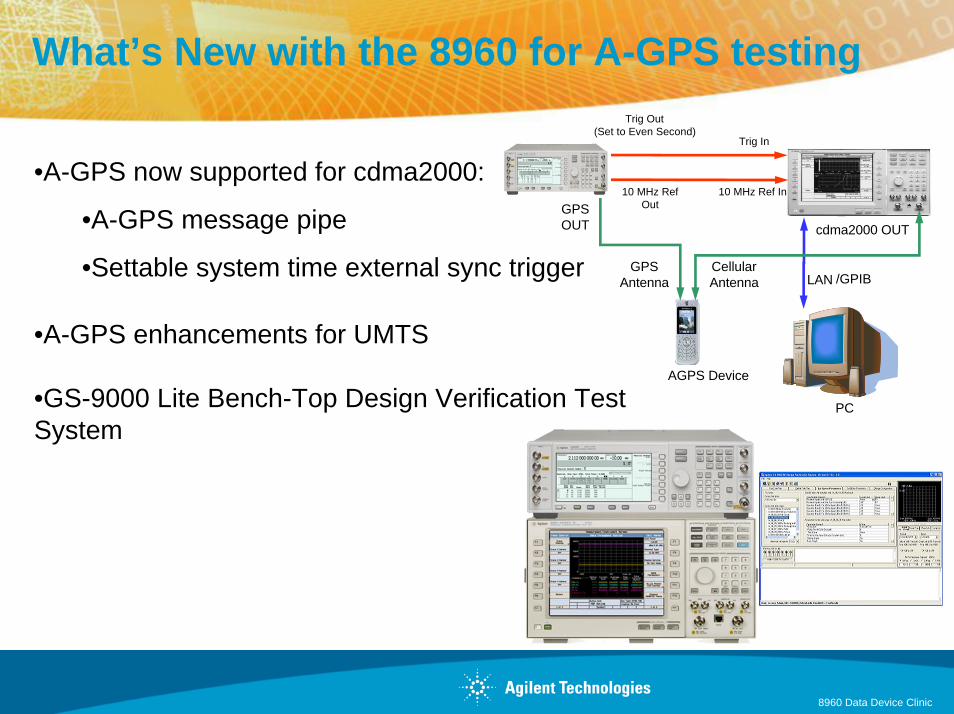
What’s New with the 8960 for A-GPS testing
•A-GPS now supported for cdma2000:
•A-GPS message pipe
•Settable system time external sync trigger
•A-GPS enhancements for UMTS
•GS-9000 Lite Bench-Top Design Verification Test System
E5515C
LAN
Trig Out (Set to Even Second)
10 MHz Ref Out
Trig In
10 MHz Ref In
AGPS Device
/GPIB
PC
GPS OUT cdma2000 OUT
Cellular Antenna
GPS Antenna
8960 Data Device Clinic
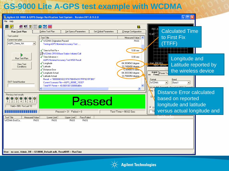
GS-9000 Lite A-GPS test example with WCDMA
Distance Error calculated based on reported longitude and latitude versus actual longitude and latitude
Longitude and Latitude reported by the wireless device
Calculated Time to First Fix (TTFF)
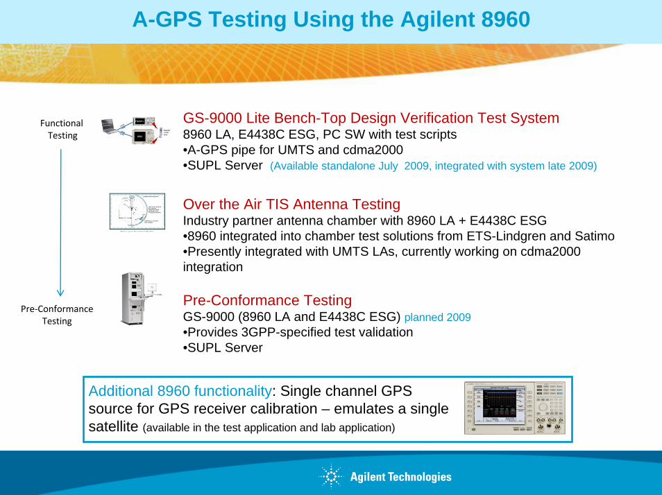
A-GPS Testing Using the Agilent 8960
GS-9000 Lite Bench-Top Design Verification Test System8960 LA, E4438C ESG, PC SW with test scripts•A-GPS pipe for UMTS and cdma2000•SUPL Server (Available standalone July 2009, integrated with system late 2009)
Over the Air TIS Antenna TestingIndustry partner antenna chamber with 8960 LA + E4438C ESG•8960 integrated into chamber test solutions from ETS-Lindgren and Satimo•Presently integrated with UMTS LAs, currently working on cdma2000 integration
Pre-Conformance TestingGS-9000 (8960 LA and E4438C ESG) planned 2009•Provides 3GPP-specified test validation•SUPL Server
Functional Testing
Pre‐Conformance Testing
Additional 8960 functionality: Single channel GPS source for GPS receiver calibration – emulates a single satellite (available in the test application and lab application)

DigRF v4 Overview
• Multi gigabit high speed serial interface to connect BB and RF-ICs
• Bus specification in mobile devices• Mobile Industry Processor Interface (MIPI)
Alliance, active standard body with key IC and handset vendors as board members
• Multilane (x2)• Packet & protocol based • Power saving modes and fast wake up
MIPI® Alliance www.mipi.org
© 2009 Agilent Technologies Page 32
PhysicalStandard
ProtocolStandard
D-PHY
CSICameraInterface
DSIDisplay
InterfaceDigRF
v4
M-PHY
DigRF v3
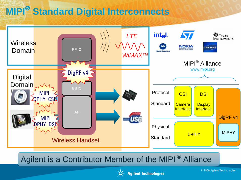
MIPI® Standard Digital Interconnects
Wireless Handset
RF IC
BB IC
AP
WiMAX™
WirelessDomain
DigitalDomain
MIPIDPHY DSI
MIPIDPHY CSI
DigRF v4
LTE
Agilent is a Contributor Member of the MIPI ® AllianceAgilent is a Contributor Member of the MIPI ® Alliance
Physical
Standard
Protocol
Standard
D-PHY
CSI
CameraInterface
DSI
DisplayInterface
DigRF v4
M-PHY
MIPI® Alliance www.mipi.org
© 2009 Agilent Technologies
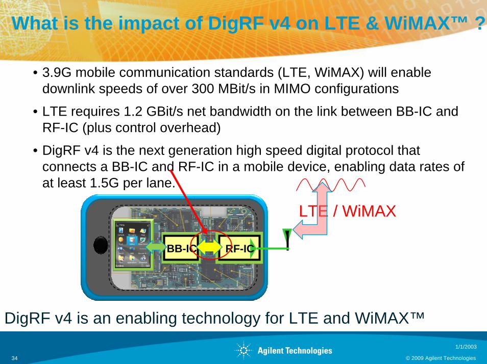
What is the impact of DigRF v4 on LTE & WiMAX™ ?
• 3.9G mobile communication standards (LTE, WiMAX) will enable downlink speeds of over 300 MBit/s in MIMO configurations
• LTE requires 1.2 GBit/s net bandwidth on the link between BB-IC and RF-IC (plus control overhead)
• DigRF v4 is the next generation high speed digital protocol thatconnects a BB-IC and RF-IC in a mobile device, enabling data rates of at least 1.5G per lane.
LTE / WiMAX
RF-ICBB-IC
DigRF v4 is an enabling technology for LTE and WiMAX™1/1/2003
© 2009 Agilent Technologies34

© 2009 Agilent Technologies 1/1/2003
Page 35Page 35
Vector Signal Analysis
RF-IC
Signal Studio
Tx
Rx
Signal Generator
Signal/Spectrum Analyzer
Agilent Solutions for DigRF v4World first DigRF v3/v4 tester including cross-domain tests with RF, SG and SA
Easy-to-use signal creation & analysis tools for both digital and RF wireless
with common software platforms
N5343A RDX - DigRF v3/v4 testerfor simulation, lane/protocol analysis,and monitor DigRF links of RFIC/BBIC
LTE / WiMAX™
W-CDMA/HSPAGSM/EDGE
DigRF Tester
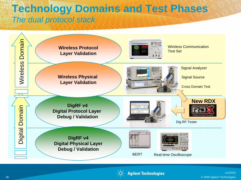
Technology Domains and Test PhasesThe dual protocol stack
Real-time OscilloscopeBERT
DigRF v4Digital Protocol Layer
Debug / Validation
DigRF v4Digital Physical Layer
Debug / Validation
Wireless ProtocolLayer Validation
Wireless Physical Layer Validation
Dig
ital D
omai
nW
irele
ss D
omai
n
Dig RF Tester
Signal Source
Signal Analyzer
Cross Domain Test
Wireless CommunicationTest Set
New RDX platform
1/1/2003© 2009 Agilent Technologies 36
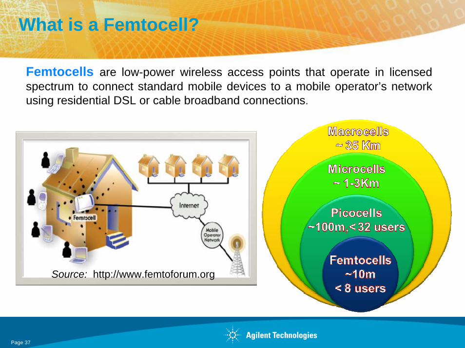
What is a Femtocell?
Femtocells are low-power wireless access points that operate in licensed spectrum to connect standard mobile devices to a mobile operator’s network using residential DSL or cable broadband connections.
Source: http://www.femtoforum.org
Page 37
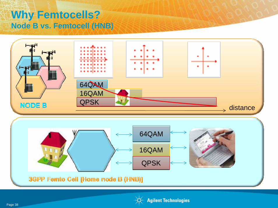
Why Femtocells?Node B vs. Femtocell (HNB)
64QAM64QAM16QAM16QAMQPSKQPSK
distance
64QAM64QAM
16QAM16QAM
QPSKQPSK
Page 38

Why Femtocell?
• Weaker indoor coverage at high carrier frequency
• Provisioning of higher data rates for many users by macro cellular coverage
• WLAN/VoIP competition by hybrid WLAN/UMTS terminals
• Backhaul cost to macro sites for high HSPA data rates
• Site acquisition and installation in urban and rural environments
• Network planning and operation
Page 39
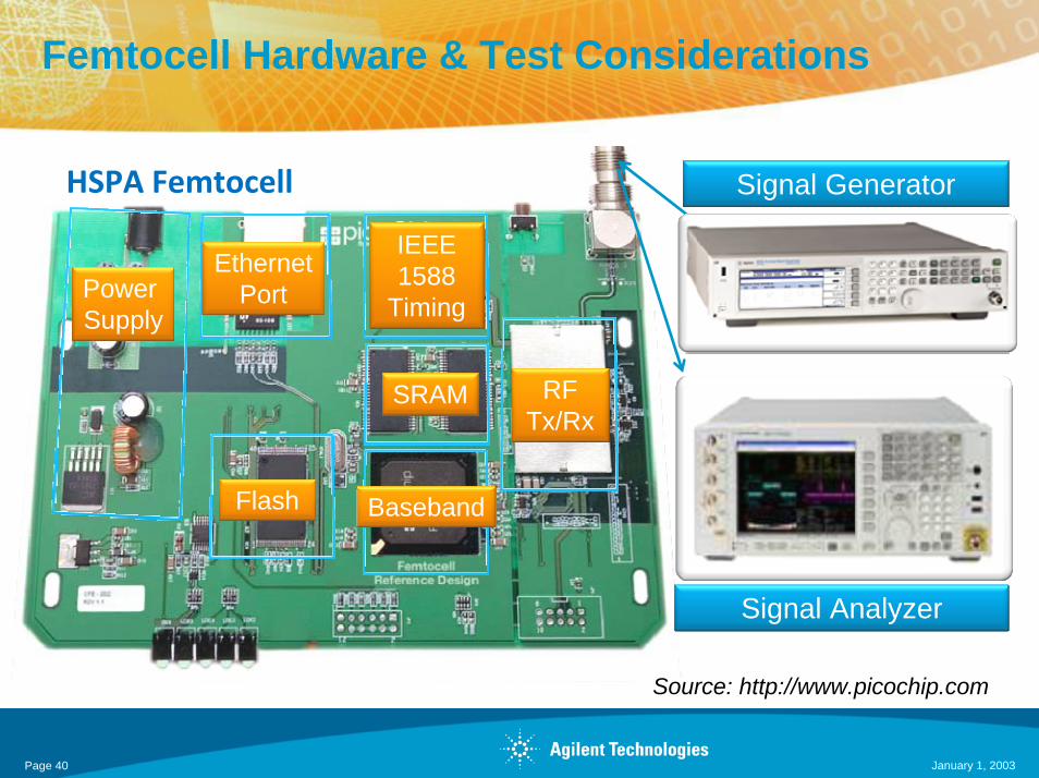
Femtocell Hardware & Test Considerations
Power Supply
Ethernet Port
Flash Baseband
SRAM
IEEE 1588
Timing
RFTx/Rx
Source: http://www.picochip.com
Signal Generator
Signal Analyzer
HSPA Femtocell
January 1, 2003Page 40

Page 41
3GPP Home Node B (HNB): Rx Test requirementSubset only
Femtocell25.820
ver 8.2.0
Base-Station25.104
ver 8.5.0
Specification HNB ValueBER shall not exceed 0.001
Local / Med / Wide range Node B Values
BER shall not exceed 0.0015.4.5.1 7.2.1 Reference sensitivity level -107dBm -107dBm/-111dBm /-121dBm
5.4.5.2 7.3.1 Dynamic range -57dBm -77dBm/-81dBm /-91dBm
5.4.5.3 7.4.1 Adjacent channel selectivity (ACS)
-91dBm -101dBm/-105dBm /-115dBm
5.4.5.4.1 7.5.1 Blocking characteristics:Minimum Requirement
-101dBm -101dBm/-105dBm /-115dBm
5.4.5.4.2 7.5.2 Blocking characteristics: Minimum Requirement - Co-
location with GSM900, DCS 1800, PCS1900, GSM850 and/or UTRA FDD
-101dBm -101dBm/-105dBm /-115dBm
5.4.5.4.3 7.5.3 Blocking characteristics : Minimum Requirement - Co-location with UTRA-TDD
-101dBm -101dBm/-101dBm /-115dBm
5.4.5.5 7.6.1 Intermodulation characteristics -101 dBm -101dB/-105 dBm/-115dBm
January 1, 2003

3GPP Home Node B (HNB): Tx Test requirementSubset only
Femtocell25.802
ver 8.2.0
Base-Station25.104
ver 8.5.0
Specification Proposed Value Current Value
5.4.4.2 6.2.1 Maximum Output Power 20 dBm (without MIMO)17dBm (with MIMO)
38 dBm [Medium range] 24 dBm [local area]
5.4.4.3 6.3.1 Frequency Error ±0.25 ppm ±0.1 ppm [Med range]±0.05 ppm [Wide range]
5.4.4.4.1 6.6.3.2.1 Spurious emissions - Protection of the BS receiver of
own or different BS
same -82dBm
5.4.4.4.2 6.6.3.4.1 Spurious emissions - Co-existence with co-located
and co-sited base stations
same -70dBm [pico 900/850] ,-82dBm
5.4.4.4.3 6.6.3.7.1.1 Spurious emissions - Co-existence with UTRA-TDD
same -52dBm
Page 42
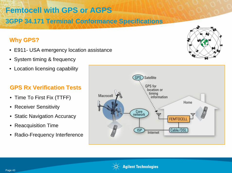
Femtocell with GPS or AGPS 3GPP 34.171 Terminal Conformance Specifications
GPS Rx Verification TestsGPS Rx Verification Tests• Time To First Fix (TTFF)
• Receiver Sensitivity
• Static Navigation Accuracy
• Reacquisition Time
• Radio-Frequency Interference
Why GPS?Why GPS?• E911- USA emergency location assistance
• System timing & frequency
• Location licensing capability
Page 43
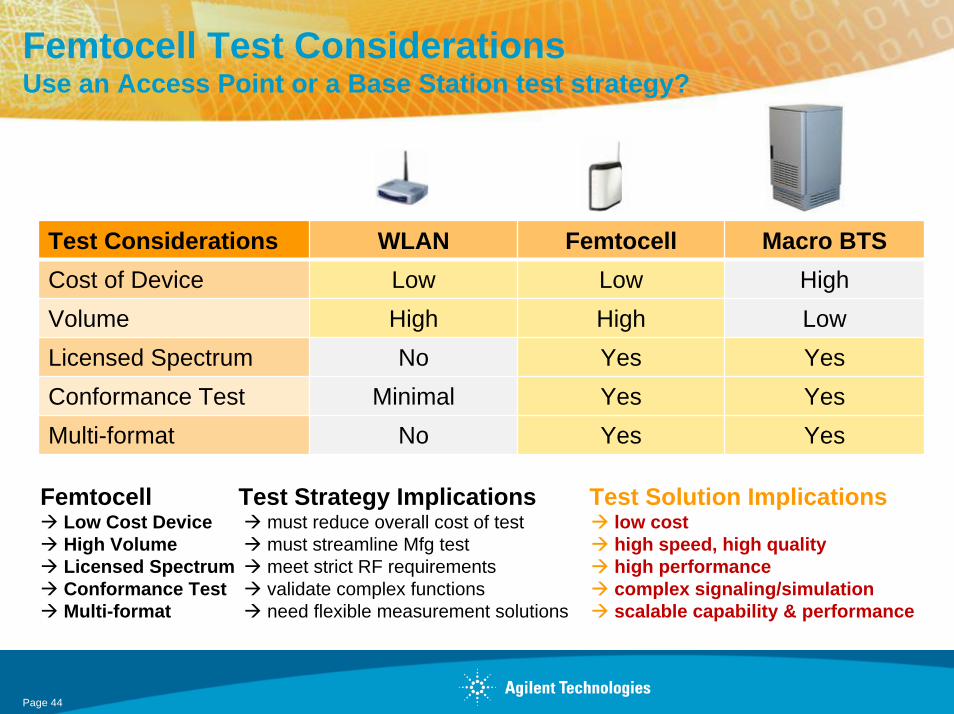
Femtocell Test ConsiderationsUse an Access Point or a Base Station test strategy?
Test Considerations WLAN Femtocell Macro BTSCost of Device Low Low HighVolume High High LowLicensed Spectrum No Yes YesConformance Test Minimal Yes YesMulti-format No Yes Yes
Femtocell Test Strategy Implications Test Solution ImplicationsLow Cost Device must reduce overall cost of test low costHigh Volume must streamline Mfg test high speed, high qualityLicensed Spectrum meet strict RF requirements high performanceConformance Test validate complex functions complex signaling/simulationMulti-format need flexible measurement solutions scalable capability & performance
Page 44

Agilent Femtocell RF Test Solutions For R&D & Manufacturing
Scalable Test SolutionsScalable Test Solutions• tailor the capability & performance from single channel
to MIMO• easily upgrade as your test needs evolve• multi-format application support
- W-CDMA, HSPA, LTE, GSM/EDGE, CDMA2000, 1xEV, WiMAX, GPS, WLAN, etc...
High PerformanceHigh Performance• power, accuracy, distortion performance, EVM,
dynamic range, bandwidth…
FastFast• switching speed• measurement speed
Low Cost of OwnershipLow Cost of Ownership• best price/performance value• outstanding reliability minimizes downtime in MFTR• low maintenance & repair cost• unrivaled worldwide service &
Application Engineer technical support
Signal Studio
Measurement Applications
MXA/EXA Signal Analyzer
MXG Vector Signal Generator
PXB MIMO Rx Tester
Page 45
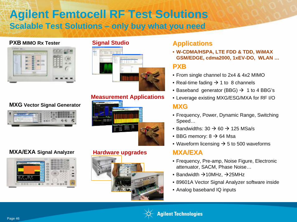
Agilent Femtocell RF Test Solutions Scalable Test Solutions – only buy what you need
MXA/EXA Signal Analyzer
MXG Vector Signal Generator
PXB MIMO Rx Tester Signal Studio
Measurement Applications
Hardware upgrades
ApplicationsApplications• W-CDMA/HSPA, LTE FDD & TDD, WiMAX
GSM/EDGE, cdma2000, 1xEV-DO, WLAN …
PXB PXB • From single channel to 2x4 & 4x2 MIMO• Real-time fading 1 to 8 channels • Baseband generator (BBG) 1 to 4 BBG’s• Leverage existing MXG/ESG/MXA for RF I/O
MXGMXG• Frequency, Power, Dynamic Range, Switching
Speed…• Bandwidths: 30 60 125 MSa/s• BBG memory: 8 64 Msa• Waveform licensing 5 to 500 waveforms
MXA/EXAMXA/EXA• Frequency, Pre-amp, Noise Figure, Electronic
attenuator, SACM, Phase Noise…• Bandwidth 10MHz, 25MHz • 89601A Vector Signal Analyzer software inside• Analog baseband IQ inputs
Page 46
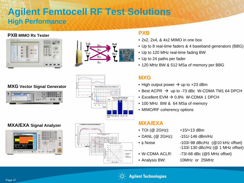
Agilent Femtocell RF Test Solutions High Performance
PXBPXB• 2x2, 2x4, & 4x2 MIMO in one box• Up to 8 real-time faders & 4 baseband generators (BBG)• Up to 120 MHz real-time fading BW• Up to 24 paths per fader• 120 MHz BW & 512 MSa of memory per BBG
MXGMXG• High output power up to +23 dBm• Best ACPR up to -73 dBc W-CDMA TM1 64 DPCH• Excellent EVM 0.8% W-CDMA 1 DPCH• 100 MHz BW & 64 MSa of memory• MIMO/RF coherency options
MXA/EXAMXA/EXA• TOI (@ 2GHz): +15/+13 dBm• DANL (@ 2GHz): -151/-146 dBm/Hz• φ Noise -103/-98 dBc/Hz (@10 kHz offset)
-133/-130 dBc/Hz (@ 1 MHz offset)• W-CDMA ACLR: -73/-68 dBc (@5 MHz offset)• Analysis BW: 10MHz or 25MHz
11h
MXA/EXA Signal Analyzer
MXG Vector Signal Generator
PXB MIMO Rx Tester
00h01h
10h
Tx0
Tx1
Rx0
Rx1
Page 47
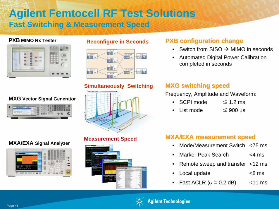
Agilent Femtocell RF Test Solutions Fast Switching & Measurement Speed
PXB configuration changePXB configuration change• Switch from SISO MIMO in seconds• Automated Digital Power Calibration
completed in seconds
MXG switching speed MXG switching speed Frequency, Amplitude and Waveform:
• SCPI mode ≤ 1.2 ms• List mode ≤ 900 μs
MXA/EXA measurement speedMXA/EXA measurement speed• Mode/Measurement Switch <75 ms
• Marker Peak Search <4 ms
• Remote sweep and transfer <12 ms
• Local update <8 ms
• Fast ACLR (σ = 0.2 dB) <11 ms
MXA/EXA Signal Analyzer
MXG Vector Signal Generator
PXB MIMO Rx Tester
Simultaneously Switching
Measurement Speed
Reconfigure in Seconds
Page 48
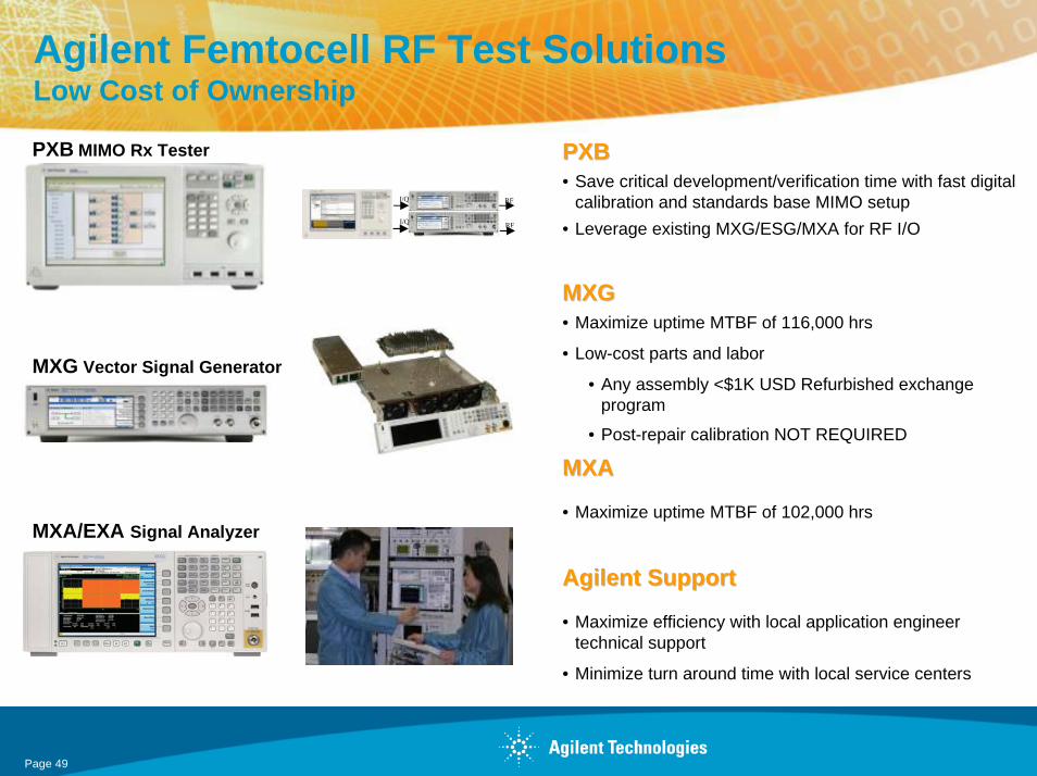
Agilent Femtocell RF Test Solutions Low Cost of Ownership
PXB PXB • Save critical development/verification time with fast digital
calibration and standards base MIMO setup• Leverage existing MXG/ESG/MXA for RF I/O
MXGMXG• Maximize uptime MTBF of 116,000 hrs
• Low-cost parts and labor
• Any assembly <$1K USD Refurbished exchange program
• Post-repair calibration NOT REQUIRED
MXAMXA
• Maximize uptime MTBF of 102,000 hrs
Agilent SupportAgilent Support
• Maximize efficiency with local application engineer technical support
• Minimize turn around time with local service centers
MXA/EXA Signal Analyzer
MXG Vector Signal Generator
PXB MIMO Rx Tester
RF
RF
I/Q
I/Q
Page 49

Femtocell Tx/Rx RF Test Setup for R&DWith Channel Emulation
Power Supply
Ethernet Port
Flash
BasebandSRAMIEEE 1588
Timing
RFTx/Rx
Ethernet Hub
10 MHz
40 ms TTI Trigger Event
1 to 50 MHz Frequency Reference *
UL
DL
AttenDuplexer
Femtocell
MXA/EXA Signal Analysis
MXG Signal Generation
Ethernet Hub
Source: http://www.picochip.com
PXB Channel Emulation
10 MHzI Q
* EXA can support 10 to 20 MHz with special option N9010AS-R13
Page 50
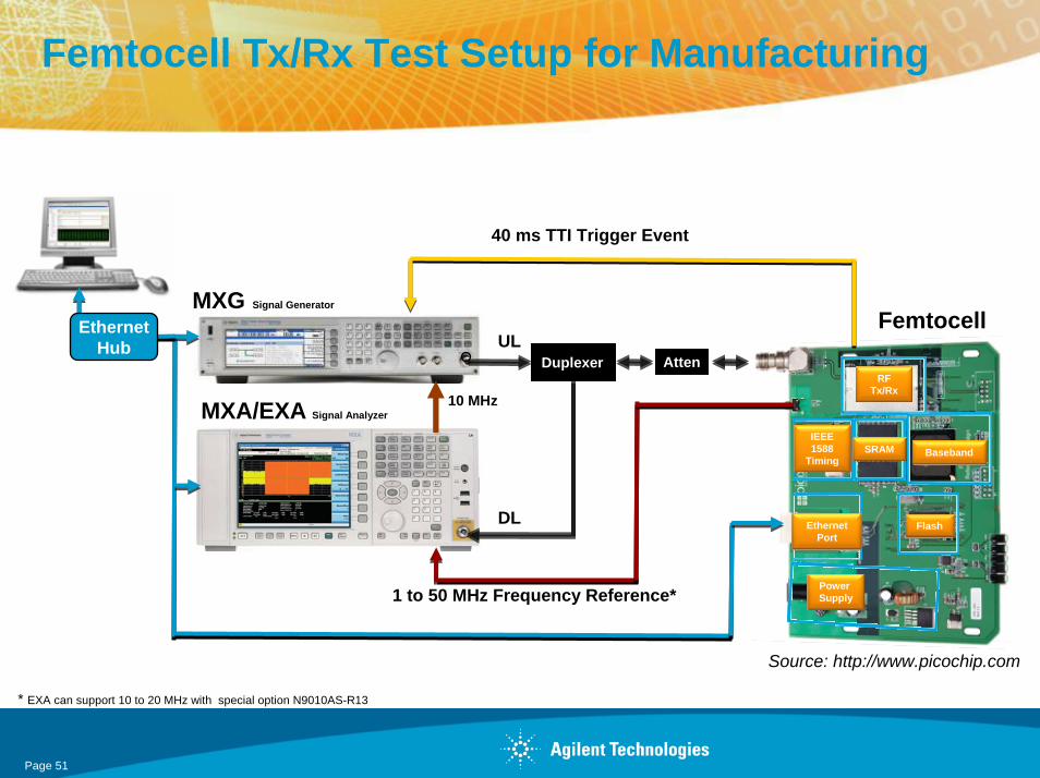
Femtocell Tx/Rx Test Setup for Manufacturing
Power Supply
Ethernet Port
Flash
BasebandSRAMIEEE 1588
Timing
RFTx/Rx
Ethernet Hub
10 MHz
40 ms TTI Trigger Event
1 to 50 MHz Frequency Reference*
UL
DL
AttenDuplexer
Femtocell
MXA/EXA Signal Analyzer
MXG Signal Generator
Ethernet Hub
Source: http://www.picochip.com
* EXA can support 10 to 20 MHz with special option N9010AS-R13
Page 51

SummaryAgilent Has The Right Tools for Femtocell RF Test
• Scalable solutions offer best price/performance value
• Industry leading speed
• Multi-format support now and in the future
• Low cost of ownership
• Backed by Agilent world wide service & support
MXA/EXA Signal Analyzer
MXG Vector Signal Generator
PXB MIMO Rx Tester Signal Studio
Measurement Applications
Page 52
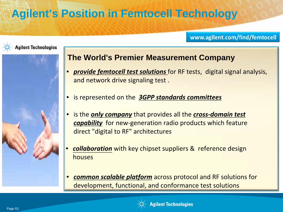
Agilent’s Position in Femtocell Technology
The World's Premier Measurement Company• provide femtocell test solutions for RF tests, digital signal analysis, and network drive signaling test .
• is represented on the 3GPP standards committees
• is the only company that provides all the cross‐domain test capability for new‐generation radio products which feature direct "digital to RF" architectures
• collaboration with key chipset suppliers & reference design houses
• common scalable platform across protocol and RF solutions for development, functional, and conformance test solutions
Page 53