Embed Size (px)
Citation preview

Varlogic NRC12 Power factor controller
User manual
DB
1215
83
User's manual
Menu Structure
DB
1216
03
Sequences
3653493EN_01.indd 2

User's manualD
1216
04
Menus
3653493EN_01.indd 3

User's manual
Power Factor Controller NRC12 USER’S MANUAL Table of Contents 1. General .............................................................................................. 5 1.1 Safety ...........................................................................................................5
1.2 Environmental conditions ..........................................................................5
1.3 Description ..................................................................................................6
2. Installation ........................................................................................ 9
3. Display ............................................................................................ 12
4. Start-up Procedure ......................................................................... 13
5. Menu Operations ............................................................................ 145.1 General .......................................................................................................14
5.2 Main Menu ..................................................................................................16
5.3 Bank Pre-Configuration ............................................................................18
5.4 Commissioning .........................................................................................195.4.1 Commissioning sequence ......................................................................................195.4.2 List of errors .............................................................................................................20
5.5 Auto Setup of Parameters .........................................................................21
5.6 Manual Setup of Parameters ....................................................................22
5.7 Measurement Menu ...................................................................................24
5.8 Parameters .................................................................................................27
5.9 Alarms Menu ..............................................................................................32
5.10 Maintenance menu ..................................................................................37
6. Miscellaneous ................................................................................ 386.1 Stepping programs ...................................................................................38
6.2 Manual calculation of response value .....................................................43
6.3 High voltage application of NRC12 ..........................................................457. Options ........................................................................................... 47
7.1 External Temperature Sensor ...................................................................47
7.2 Controller Communication Adapter .........................................................47
8. Glossary .......................................................................................... 48
9. Technical specifications ................................................................ 56
3653493EN_01.indd 4

User's manual
1. General 1.1 SafetyThe following precautions must be taken into account when installing and operating the controller: @@
The installation of the controller must be performed by a qualifi ed electrician Do not touch the connectors when the controller is energized, make sure that the
operating voltage is disconnected before touching any parts located on the rear side of the controller
Do not open a live current circuit, this may cause dangerous overvoltages. Always short circuit the current transformer (CT) before replacing or removing the controller installed in a bank.
@
@@
Do not open the controller casing, there are no user serviceable parts inside External computing devices connected to the communication connector of Power
Factor Controller have to comply with the standard IEC 60950-1
For better understanding of the terminology used, please refer to the Glossary (chapter 8) at the end of this manual. 1.2 Environmental conditions The controller is designed for the following environmental conditions: @@@@
Indoor use Altitude up to 2000 m Ambient temperatures within 0°…+60°C Maximum relative humidity 80 percent for temperatures up to 31°C decreasing
linearly to 50 percent relative humidity at 40°C Mains supply voltage fluctuations not to exceed –20/+15 percent of the nominal@
voltage @
@
Transient overvoltage for the Mains supply according to installation categories III (IEC 61010-1)
Pollution degree 2 (IEC 61010-1)
3653493EN_01.indd 5

User's manual
1.3 Description Front view:
DB
1215
86
Legend
A Display B Keys C Opening of door D Door E Mounting bracket for panel mounting installation
3653493EN_01.indd 6

User's manual
Rear view:
DB
1215
87
Legend
F Step output connectors G Name plate H Mounting bracket for panel mounting installation I Fixing spring for DIN-rail mounting J Current, voltage, temperature sensor and target cos ϕ connection inputs K Fan and alarm outputs L DIN-rail mounting installation area M Controller Communication Adapter (CCA-01) cover
3653493EN_01.indd 7

User's manual
Side view:
DB
1215
88
Legend
N DIN-rail fi xing spring O Air inlet for temperature measurement
See Chapter 9 for technical details.
3653493EN_01.indd 8

User's manual
2. Installation The controller is designed for either panel (cut-out 138 x 138 mm) or DIN-rail installation. It is locked to a panel by a side fitting springs or to the rail by a screwdriver-operated fi xing spring.
There are two ways of connecting the controller to the network.
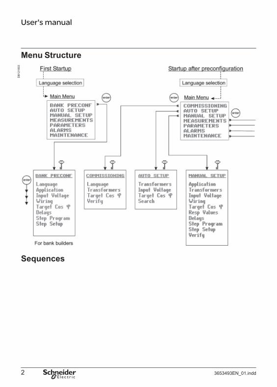
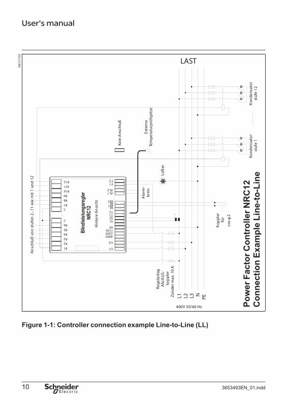
@ Voltage LN (Line – Neutral) ⇒ CT on the same line phase as voltage measurement. For LN wiring Voltage setting should be L1-N and - Current setting should be L1.
@ Voltage LL (Line – Line) ⇒ CT normally on the remaining phase (normally phase L1). For LL wiring Voltage setting should be L2-L3 and Current setting should be L1.
Separated inputs exist for measurement voltage ("U1" and " U2") and supply voltage ("0V" and "110V"/"230V"/"400V"). The controller can automatically correct incorrect measurement connection when Auto Setup is selected from the main menu.
External temperature sensor can be installed close to the devices to be watched and connected to inputs "T1" and "T2". The cable used needs to be certifi ed to national requirements relevant to controller installation voltage.
Alternative target cos ϕ can be controlled by using external relay contact connected between inputs "ϕ1" and "ϕ2". The cable used needs to be certified to national requirements relevant to controller installation voltage.
Caution: For application in HV network, look first at chapter 6.3.
Control switch of capacitorbank switches the power to the controller.In ambient temperature of 60°C the temperature class of connection wires must be at least 80°C.
Notes on installation: A switch or circuit-breaker shall be included in the building installation. It shall be in close proximity to the equipment and within easy reach of the operator. It shall be marked as the disconnecting device for the equipment. An equipment switch or circuit-breaker employed as a disconnecting device shall comply with relevant requirements of IEC 60947-1 and IEC 60947-3.
Overcurrent protection devices such as fuse or miniature circuit breaker with a rating of no more than 10 A shall be connected in supply conductors. The overcurrent protection devices need to be certified to national requirements.
3653493EN_01.indd 9
DB
1217
22
Ans
chlu
ß vo
n st
ufen
2...1
1 w
ie m
it 1
und
12
User's manual
R1 U1
U2
400V 230V 11 0 V 0V
S1 S2 T1 T2
1 2
AL 1 AL 2
F1 F2
R2 R3 R4 R5 R6
C
C R7 R8 R9
R10 R11 R12
Blind
leist
ungs
regle
rNR
C12
Lüft
er
Rege
lanl
agA
N/A
US
kop
pler
Ala
rm
krei
s
LAST
Kein
Ans
chlu
ß
Hin
tere
Ans
icht
Kop
pler
fü
rco
s 2
Kond
ensa
tor-
Kon
dens
ator
Exte
rne
Tem
pera
turp
rüfs
pitz
e
Pow
er F
acto
r Con
trol
ler N
RC
12
Zünd
er m
ax. 1
0 A
L1 L2 L3 N PE
400V 50/60 Hz
Figure 1-1: Controller connection example Line-to-Line (LL)
3653493EN_01.indd
stuf
e 1
stuf
e 12
C
onne
ctio
n Ex
ampl
e Li
ne-to
-Lin
e
10
DB
1217
23
Ans
chlu
ß vo
n st
ufen
2...1
1 w
ie m
it 1
und
12
User's manual
R1 U1
U2
400 V 230 V 11 0 V 0V
S1 S2 T1 T2
�1 �2
AL 1 AL 2
F1 F2
R2 R3 R4 R5 R6
C
C R7 R8 R9
R10 R11 R12
Lüft
er
Rege
lanl
agA
N/A
US
kop
pler
LAST
Kein
Ans
chlu
ß
Blind
leist
ungs
regle
rNR
C12
Hin
tere
An
sich
t
Exte
rne
Tem
pera
turp
rüfs
pitz
e A
larm
kr
eis
Kop
pler
fü
rco
s 2
Pow
er F
acto
r Con
trol
ler N
RC
12
Zün
der m
ax. 1
0 A
L1 L2 L3 N PE
400V 50/60 Hz
Figure 1-2: Controller connection example Line-to-Neutral (LN)
3653493EN_01.indd
Kond
ensa
tor-
Kond
ensa
tor-
Con
nect
ion
Exam
ple
Line
-to-N
eutr
al
stuf
e 1
stuf
e 12
11
User's manual
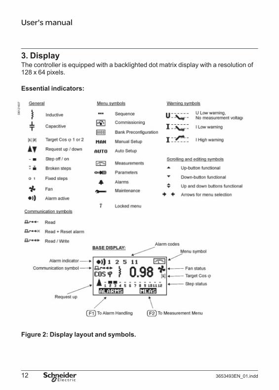
3. Display The controller is equipped with a backlighted dot matrix display with a resolution of 128 x 64 pixels.
Essential indicators:
DB
1216
07
Figure 2: Display layout and symbols.
3653493EN_01.indd 12

User's manual
4. Start-up Procedure Before connecting power, check the wiring of all controller terminals. Check carefully for correct operating voltage. Selection of wrong voltage input can permanently damage the controller.
After the first power switch-on, the controller will automatically ask for the language setting of the menu.
DB
1216
08
Figure 3: Language setting dialog.
At any time press button for help screen .
3653493EN_01.indd 13
User's manual
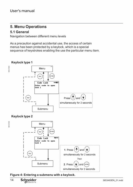
5. Menu Operations 5.1 General Navigation between different menu levels
As a precaution against accidental use, the access of certain menus has been protected by a keylock, which is a special sequence of keystrokes enabling the use the particular menu item.
Keylock type 1
Keylock type 2
DB
1216
09D
B12
1609
Figure 4: Entering a submenu with a keylock. 3653493EN_01.indd 14
User's manualD
B12
1612
D
B12
1611
DB
1216
10
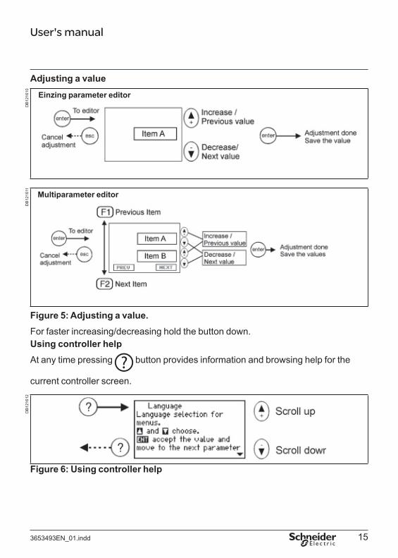
Adjusting a value
Multiparameter editor
Einzing parameter editor
Figure 5: Adjusting a value. For faster increasing/decreasing hold the button down. Using controller help At any time pressing button provides information and browsing help for the
current controller screen.
Figure 6: Using controller help
3653493EN_01.indd 15
User's manual
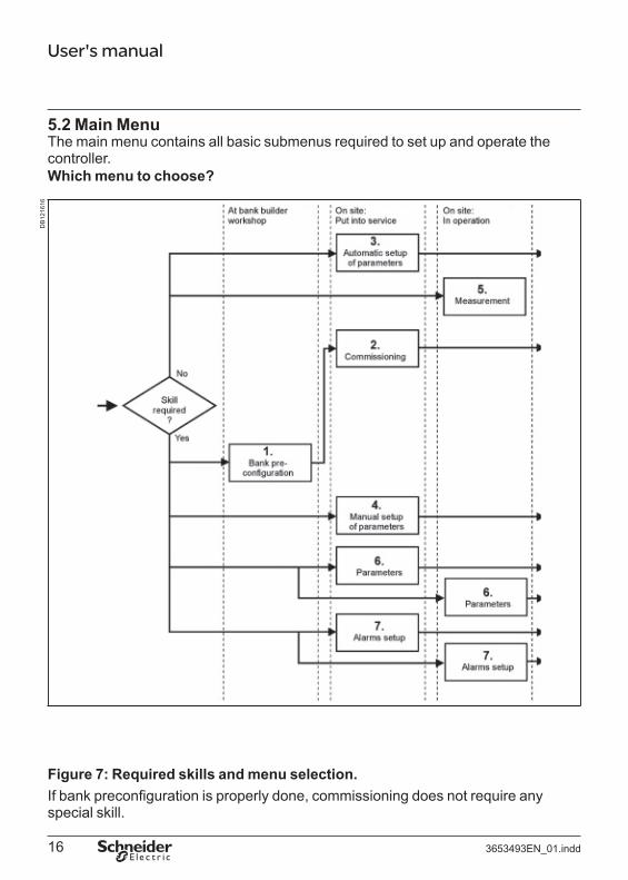
5.2 Main Menu The main menu contains all basic submenus required to set up and operate the controller. Which menu to choose?
DB
1216
16
Figure 7: Required skills and menu selection. If bank preconfiguration is properly done, commissioning does not require any special skill.
3653493EN_01.indd 16

User's manualD
B12
1617
Figure 8: Main menu.
(1) Bank pre-configuration When factory settings have not been changed,this menu provides the means of pre-configuringthe bank at the workshop. After pre-configuration,this menu topic is replaced by ( 2) Commissioning, by which the controller istaken into service. (3) Automatic setup of parametersIn the event that the controller has not been pre-configured, an inexperienced user canautomatically set up all the characteristics of thebank and bring it into service. (4) Manual setup of parametersIn the event that the controller has not been pre-configured, an experienced user can manuallyset up all the characteristics of the bank andbring it into service. (5) MeasurementThe measurement menu contains the most common measurements taken from the network and provides some information about the bank.This is a read-only menu. (6) ParametersAt any time, an experienced user can access themost common operating parameters from thismenu. Unlike the configuration and setupsequences, this is a menu allowing a free andunrestricted entry into all its items and should beused when an occasional parameter access isneeded. (7) Alarm settingsTo show status and adjust the parameters of alarms. (8) MaintenanceThe maintenance menu provides usefulinformation about the usage of the bank,capacitors and contactors. Auxiliary settings and action have also been provided. This menu is basically intended for use by the manufacturer’smaintenance team.
3653493EN_01.indd 17

User's manualD
B12
1618
5.3 Bank Pre-ConfigurationThis menu item is a forced sequence, meaning that all items must be accessed before the preconfiguration takes place. Notes: 1) Do not use the Bank Pre-Configuration menu for HV network applications
2) Select “Cancel” at the end of Bank Pre-Configuration menu if 1st step isfixed
The sequence can be interrupted by pressing key.
See Glossary (chapter 8) for definitions.
Figure 9: Bank pre-configuration. 3653493EN_01.indd 18

User's manual
5.4 Commissioning 5.4.1 Commissioning sequence A pre-configured controller is put into service by this menu. The sequence contains an automatic C/K value detection and automatic parameter verification to check that the manually entered parameters comply with the network.
See Glossary (chapter 8) for parameter definitions.
Notes: The use of Commissioning menu is forbidden on HV network applications.
DB
1216
19
Figure 10: Commissioning. 3653493EN_01.indd 19
User's manual
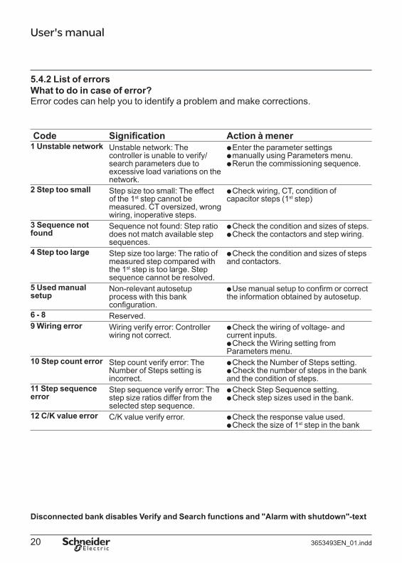
5.4.2 List of errors What to do in case of error? Error codes can help you to identify a problem and make corrections.
Code Signification Action à mener 1 Unstable network Unstable network: The
controller is unable to verify/search parameters due toexcessive load variations on the network.
QQQ
Enter the parameter settingsmanually using Parameters menu.Rerun the commissioning sequence.
2 Step too small
3 Sequence notfound
4 Step too large
5 Used manual setup
6 - 8
Step size too small: The effect of the 1st step cannot bemeasured. CT oversized, wrong wiring, inoperative steps. Sequence not found: Step ratiodoes not match available step sequences. Step size too large: The ratio of measured step compared withthe 1st step is too large. Stepsequence cannot be resolved. Non-relevant autosetupprocess with this bank configuration. Reserved.
Check wiring, CT, condition of capacitor steps (1st step) Q
Q Q
Check the condition and sizes of steps.Check the contactors and step wiring.
Check the condition and sizes of stepsand contactors. Q
Use manual setup to confirm or correct the information obtained by autosetup. Q
9 Wiring error Wiring verify error: Controllerwiring not correct.
Check the wiring of voltage- andcurrent inputs.
Check the Wiring setting fromParameters menu.
Q
Q
10 Step count error Step count verify error: The Number of Steps setting is
Check the Number of Steps setting.Check the number of steps in the bank
incorrect. and the condition of steps. 11 Step sequence Step sequence verify error: The Q
Q
Check Step Sequence setting.Check step sizes used in the bank.
Check the response value used.Check the size of 1st step in the bank
error step size ratios differ from the selected step sequence.
12 C/K value error C/K value verify error.
Disconnected bank disables Verify and Search functions and "Alarm with shutdown"-text
3653493EN_01.indd 20
User's manual
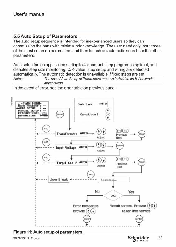
5.5 Auto Setup of ParametersThe auto setup sequence is intended for inexperienced users so they can commission the bank with minimal prior knowledge. The user need only input three of the most common parameters and then launch an automatic search for the other parameters.
Auto setup forces application setting to 4-quadrant, step program to optimal, and disables step size monitoring. C/K-value, step setup and wiring are detected automatically. The automatic detection is unavailable if fixed steps are set. Notes: The use of Auto Setup of Parameters menu is forbidden on HV network
applications. In the event of error, see the error table on previous page.
DB
1216
20
Figure 11: Auto setup of parameters. 3653493EN_01.indd 21

User's manual
5.6 Manual Setup of Parameters
The manual setup sequence is intended for experienced users. There are nine important parameters to input before the controller can be taken into service. This sequence is completed by an automatic verification of the parameters entered in this sequence.
This menu item is a forced sequence, meaning that all items must be accessed before the validation of the setup takes place.
The sequence can be interrupted by pressing key.
See Glossary (chapter 8), for parameter definitions.
In case of error in verification, refer to error table, page 20.
Notes: The use of verification in Manual Setup of Parameters is forbidden on HVnetwork applications
3653493EN_01.indd 22

User's manualD
B12
1621
Figure 12: Manual setup of parameters. 3653493EN_01.indd 23
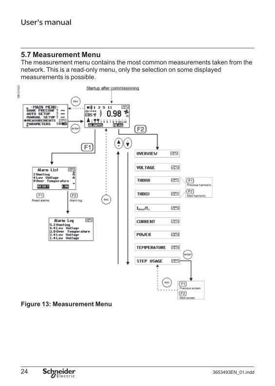
User's manual
5.7 Measurement Menu The measurement menu contains the most common measurements taken from the network. This is a read-only menu, only the selection on some displayed measurements is possible.
DB
1216
22
Figure 13: Measurement Menu
3653493EN_01.indd 24

User's manual
Measurement Explanations:
Screen Item Description List of detected alarms. A = Active alarm. Log of 5 latest alarms. Alarm log can be cleared using "Clear Alarm Log"-function in Maintenance menu. Input voltage (VLL Line to Line or VLN Line to Neutral) Total harmonic distortion of voltage Capacitor overload factor Reactive power Internal temperature Input voltage (VLL Line to Line or VLN Line to Neutral) and voltage limits. If nominal value is not standard, graphical display is in % scale. Total harmonic distortion of voltage and alarm limit for it. Total harmonic distortion of voltage and harmonic components.Total harmonic distortion of current and harmonic components.Capacitor overload factor (measured current ratio to nominal current at nominal voltage) and alarm limit for it.Active current of CT primary (phase current)Reactive current of CT primary.Apparent current of CT primary.Active power (3-phase total power)Reactive power.Apparent power.Internal temperature, fan limit and alarm limit.External temperature, only present if external temperature sensor connected. Number of step connections and usage hours.
3653493EN_01.indd 25

User's manualD
B12
1623
D
B12
1636
DB
1216
35
Nominal value Alarm limit Alarm limit
LL connection of voltage
Measured value Figure 13-2: Measured value and alarm limits.
Harmonic distortion values
Total harmonic distortion Values of delected harmonics
Keys for scrolling harmonic Figure 13-3: Graphs showing voltage harmonics.
Fan limit Alarm limit
Fan Internal temperature External temperature (Only present if external
Temperature values temperature sensor is connected)
Figure 13-4: Temperature values and fan status.
3653493EN_01.indd 26
User's manual
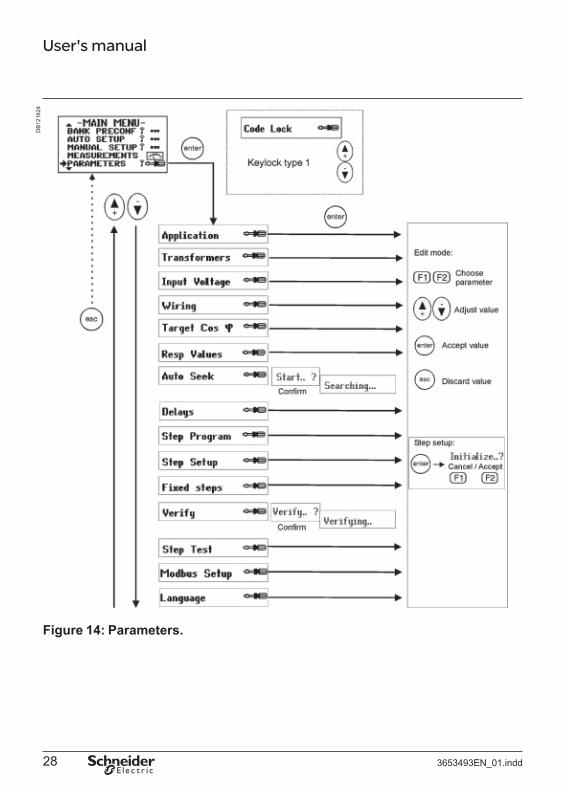
5.8 Parameters
CAUTION: In case of installation in a HV bank (with VT), you must adjust the defaultfactory settings. The reconnection delay must be changed to a largervalue (e.g. 600 secs) to prevent destruction of capacitors.
The most common operating parameters can be accessed from this menu.
Unlike the configuration and setup sequences presented earlier in this text, this is a menu allowing a free and unrestricted entry into all of its items and should be used when occasional parameter access is needed. Restart the controller after major changes in parameters.
To start the step size monitoring, set number of steps, step sequence and the size of the 1st step (reactive power and voltage), initialize the measurement (asked when exiting the editor). If wanted, set the alarm on from the alarm menu. If the step size is set to 0 the step size monitoring is disabled.
Step size monitoring cannot be used when Loads change constantly and rapidly If the 1st step is very small compared to total measurement scale If HV application is selected (automatically disabled)
Fixed steps cannot be monitored or verified. Setting 1st step fixed disables also search and seek functions.
See Glossary (chapter 8), for parameter definitions.In case of error in verifying, refer to error table, page 20.
@@@
3653493EN_01.indd 27
User's manualD
B12
1624
Figure 14: Parameters.
3653493EN_01.indd 28

User's manual
Parameter Explanations:
Screen Item Description 2 quadrant application: Only use of power, the most common situation.4 quadrant application: Power generation possible.Application is forced to 4-quadrant in Auto Setup.Network voltage range of application.
Current transformer: primary and secondary current.Voltage transformer ratio. Used if voltage range with VT selected.Nominal input voltage reference value at input voltage terminals U1 and U2. For voltage alarms. In VT application, the secondary voltage is entered and the calculated primary voltage is displayed.Location of voltage measurement: L2-L3, L3-L1, L1- L2, L1-N, L2-N or L3-N. Detected in Auto Setup and Auto seek, checked with verify function. See also Installation (chapter 2).Location of current measurement: L1, L2 or L3.Detected in Auto Setup and Auto seek, checked with verify function. See also Installation (chapter 2).Detected in Auto Setup and Auto seek, checked with verify function.DIRECT = Normal polarity of current measurement.REVERSE = Inverted polarity of current measurement.AUTO = Automatic current polarity detection, disabled in 4 quadrant applications.
3653493EN_01.indd 29

User's manual
Screen Item Description Primary Target Cos φ (normally used when control input is open), 0.80 ind - 0.90 cap. Secondary Target Cos φ (selected by closing relay input), 0.80 ind - 0.90 cap. Symbol in Base Display shows the status of control relay. C/K-value for inductive reactive power, 0.01 - 1.99. Calculate using a formula or get from C/K value table. Detected in Auto Setup and Auto seek, or manually if wanted. Checked with verify function. C/K-value for capacitive reactive power, 0.01 - 1.99. Calculate using a formula or get from C/K value table. Detected in Auto Setup and Auto seek, or manually if wanted. Checked with verify function. Automatic C/K-value seek, connects and disconnects first step several times. Do not use on HV network applications! 10s - 900s. Reconnection delay and response delay. Reconnection delay is used to protect the step capacitors (don't use too short values). Response delay, the minimum time between changes in steps, is defined as 20 % of reconnection delay, min 10 s. The default value corresponds to capacitors with internal discharge resistors 50V 1 min. Reconnection is faster when using Optimal step program.
3653493EN_01.indd 30

User's manual
Screen Item Description (Forced to Optimal in Auto Setup). Normal, suitable for step sequence 1.2.4.4.4 Circular 1.1.1, suitable for step sequence 1.1.1.1.1 Circular 1.2.2, suitable for step sequence 1.2.2.2.2 Stack, suitable for step sequence 1.1.1.1.1 Optimal, suitable for several step sequences Number of steps, 1 -12. Detected in Auto Setup, checked with verify function. Step sequence (needed for optimal stepping program, step size monitoring function and alarm 12). Detected in Auto Setup, checked with verify function. Size of first step at given voltage level (next parameter) 1kvar - 400kvar, for step size monitoring. 0 = step size monitoring disabled. See Alarms Menu (chapter 5.9) / Alarm 12 Nominal voltage of step (the line-to-line voltage) A: Automatic (default) 0: Step fi xed OFF 1: Step fi xed ON Steps set fixed are not included in any automatic functions. Fixed steps and Optimal Stepping Program cannot be used together. Automatic verification of C/K, steps and wiring. In case of an error refer to error table, page 20. Do not use in HV network applications! Manual connection of steps for testing.
3653493EN_01.indd 31

User's manual
Screen Items Description 2 digits containing correct message total counter +2 digits containing faulty message counter +2 digits containing replied message counter.The use of controller's communication.NONE = Communication disabledREAD = Communication reads informationREAD/RESET = Communication reads information and resets alarms.READ/WRITE = Communication reads and writes information.Modbus slave address of the controller. Bit rate used for data transmission. Language selection of user interface.
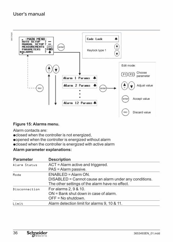
5.9 Alarms Menu In Alarms menu, each individual alarm can be enabled or disabled. Alarms 1-11 are enabled and alarm 12 is disabled as default. Alarm screen also shows whether the alarm is active or passive.
Also, some alarm triggering levels can be adjusted. Disconnection of steps due to alarms 2, 9, 10 can be enabled or disabled from alarm settings.
Once an alarm condition is detected, the corresponding alarm number is shown at the upper part of the display, and the alarm symbol becomes visible. The alarm relay is also activated.
Alarm indications can be reset in base display alarm dialog ( F1 ), this clears all passive alarms. If alarm condition is still active, the alarm cannot be reset.
3653493EN_01.indd 32

3
12
User's manual
List of alarm descriptions and limits: Alarm Alarm Description Limit, limitNo. adjustment 1 Out of Steps No steps left to connect. Network is
still inductive and request for more steps exist.
2 Hunting Continuing more/fewer step request 10 min detected.
Abnormal Current flows, but cos ϕ out of range. Ind. < 0.50, cap. < 0.80 Cos ϕ
4 Low voltage 80% 5 Over No steps left to disconnect, network
is still capacitive. 6 Wrong Frequency detected at startup ± 2 Hz of nominal at
frequency neither 50 Hz nor 60Hz. startup. 7 Over Current 115% of nominal 8 Over Voltage 110% ( 30 min ) or
120% (1 min) 9 Over If external temperature sensor is Temperature limit
Temperature installed, only external temperature setting, default 50°C is watched.
10 Too High Harmonic distortion of voltage over THD(U) limit setting, THD(U) limit. default 7%.
11 Cap OverloadHarmonic distortion or resonance IRMS/I1 limit setting, polluted current, overload factor IRMS/ default 1.5. I1 over limit.
Cap Output Capacitance is measured and Low watched during connection and
disconnection. Step sizes must be configured for step size monitoring (see Parameters/Step Setup).
Capacitor value < 75 % nominal
3653493EN_01.indd 33

User's manual
List of alarm causes and actions: Alarm Alarm Possible cause Controller action No. 1 Out of Steps Wiring or LL/LN defi nition error.
Undersized bank. 2 Hunting Too small C/K value. If disconnection in
Wrong program choice. alarm setup is Defective capacitors. ON disconnects bank
for 10 minutes. No disconnection as default.
3 Abnormal cosWiring mistake. ϕ Over capacitive network (welded
contactors) Too low current.
4 Low voltage Disconnection till voltage returns.
5 Over Wiring or LL/LN defi nition error. Improper use of fi xed steps.
6 Wrong Wrong or unstable network Stop regulation. No frequency frequency detected at startup. automatic restart.
7 Over Current Undersized CT. 8 Over Voltage Temporary
disconnection of steps during alarm and delay after that.
9 Over Ambient temperature too high Temporary Temperature Defective cooling system. disconnection of steps
during alarm and delay after that, if disconnection in alarm setup is ON. Disconnection as default.
3653493EN_01.indd 34
12
User's manual
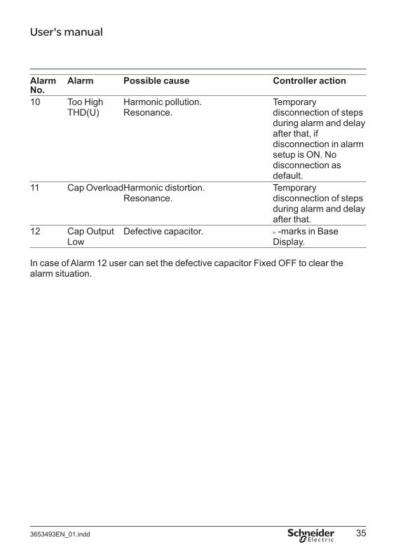
Alarm Alarm Possible cause Controller action No. 10 Too High
THD(U) Harmonic pollution. Resonance.
Temporary disconnection of steps during alarm and delay after that, if disconnection in alarm setup is ON. No disconnection as default.
11 Cap OverloadHarmonic distortion. Resonance.
Temporary disconnection of steps during alarm and delay after that.
Cap Output Defective capacitor. -marks in Base Low Display.
In case of Alarm 12 user can set the defective capacitor Fixed OFF to clear the alarm situation.
3653493EN_01.indd 35
User's manualD
B12
1625
QQQ
Figure 15: Alarms menu. Alarm contacts are:
closed when the controller is not energized, opened when the controller is energized without alarm closed when the controller is energized with active alarm
Alarm parameter explanations:
Parameter Description ACT = Alarm active and triggered.PAS = Alarm passive.ENABLED = Alarm ON.DISABLED = Cannot cause an alarm under any conditions. The other settings of the alarm have no effect.For alarms 2, 9 & 10.ON = Bank shut down in case of alarm.OFF = No shutdown.Alarm detection limit for alarms 9, 10 & 11.
3653493EN_01.indd 36
User's manual
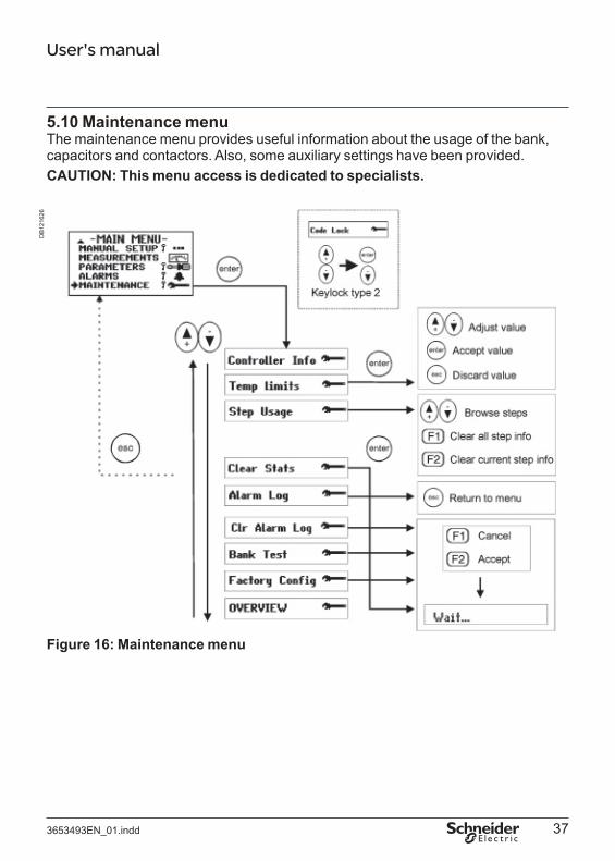
5.10 Maintenance menu The maintenance menu provides useful information about the usage of the bank, capacitors and contactors. Also, some auxiliary settings have been provided. CAUTION: This menu access is dedicated to specialists.
DB
1216
26
Figure 16: Maintenance menu
3653493EN_01.indd 37
User's manual
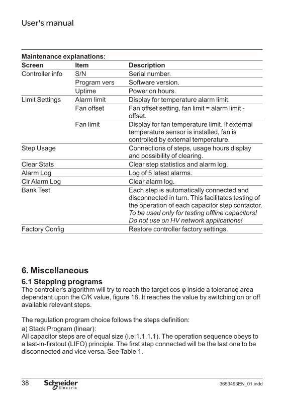
Maintenance explanations:Screen Item DescriptionController info S/N Serial number.
Program vers Software version. Uptime Power on hours.
Limit Settings Alarm limit Display for temperature alarm limit. Fan offset Fan offset setting, fan limit = alarm limit -
offset. Fan limit Display for fan temperature limit. If external
temperature sensor is installed, fan is controlled by external temperature.
Step Usage Connections of steps, usage hours display and possibility of clearing.
Clear Stats Clear step statistics and alarm log. Alarm Log Log of 5 latest alarms. Clr Alarm Log Clear alarm log. Bank Test Each step is automatically connected and
disconnected in turn. This facilitates testing of the operation of each capacitor step contactor. To be used only for testing offl ine capacitors! Do not use on HV network applications!
Factory Config Restore controller factory settings.
6. Miscellaneous 6.1 Stepping programsThe controller's algorithm will try to reach the target cos φ inside a tolerance area dependant upon the C/K value, figure 18. It reaches the value by switching on or off available relevant steps.
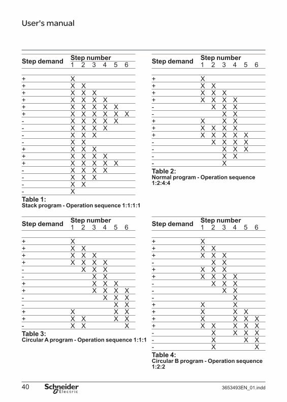
The regulation program choice follows the steps definition:a) Stack Program (linear):All capacitor steps are of equal size (i.e:1.1.1.1). The operation sequence obeys to a last-in-firstout (LIFO) principle. The first step connected will be the last one to be disconnected and vice versa. See Table 1.
3653493EN_01.indd 38

User's manual
b) Normal program (2+ linear)Normal program can be used on bank whose step ratio is 1.2.4.4.. The linear sequence starts with the 3rd step. The two first steps are used as fi ne-tuning. The controller always start by switching the first step then the second. Other steps are used successively See Table 2.c) Circular 1:1:1 programAll capacitor steps are of equal size (i.e:1.1.1.1). The operation sequence obeys the first-in-firstout (FIFO) principle. With this stepping program the amount of on- and off-connections at each step will eventually be the same. The first step connected will be the first one to be disconnected and vice versa. Then a circular sequence is followed. In order to operate correctly, the number of steps programmed into the controller must strictly comply with the number of physical steps See Table 3.d) Circular 1:2:2 program (1+Circular)Circular B program can be used on a bank whose step ratio is 1.2.2.2. The fi rst step is used as tuning after the activating limit is exceeded. The circular sequence starts with the 2nd step. See Table 4.e) Optimal Program:The optimal program operates with many step configurations:1.1.1.1.1 1.1.2.2.2 1.1.2.3.3 1.1.2.4.4 1.2.2.2.2 1.2.3.3.3 1.2.3.4.4 1.2.3.6.6 1.2.4.4.4 1.2.4.8.8
The target cos φ power is reached using the fewest number of steps in minimal time. Like the circular program, this algorithm equalizes the usage of largest steps.
This program uses optimally selected step sizes when approaching the target power and at the same time the response delays are shortened, particularly if there is a large requirement for compensation power or if the network suddenly becomes capacitive. As circular program, this stepping program keeps the usage of steps even.
Optimal program is disabled with fixed steps and vice versa.
3653493EN_01.indd 39
User's manual
Step numberStep demand 1 2 3 4 5 6
+ X + X X + X X X + X X X X + X X X X X + X X X X X X - X X X X X - X X X X - X X X - X X + X X X + X X X X + X X X X X - X X X X - X X X - X X - X Table 1:Stack program - Operation sequence 1:1:1:1
Step numberStep demand 1 2 3 4 5 6
+ X + X X + X X X + X X X X - X X X - X X + X X X + X X X X - X X X - X X + X X X + X X X X - X X X Table 3: Circular A program - Operation sequence 1:1:1
Step demand Step number1 2 3 4 5 6
+ X + X X + X X X + X X X X - X X X - X X + X X X + X X X X + X X X X X - X X X X - X X X - X X - X Table 2: Normal program - Operation sequence1:2:4:4
Step demand Step number1 2 3 4 5 6
+ X + X X + X X X - X X + X X X + X X X X - X X X - X X - X + X X + X X X + X X X X + X X X X X - X X X X - X X X - X Table 4: Circular B program - Operation sequence1:2:2
3653493EN_01.indd 40
X

User's manual
Comparison between normal and optimal program:
Normal program will reach the cos ϕ target value by successive connection/ disconnection of capacitors corresponding to the smallest step value.
Optimal program will reach the target cos ϕ value by successive connection/ disconnection of capacitors corresponding to the highest relevant and available step value.
3653493EN_01.indd 41

User's manual
Optimal Stepping Programm:
Normal Stepping Programm:
DB
1216
27D
B12
1627
Figure 17: Regulation example - Optimal vs. Normal
3653493EN_01.indd 42

User's manual
6.2 Manual calculation of response value. Normally the response value, more generally known as the C/K value, is set automatically as a part of the Auto Setup sequence, but there are cases when these values must be entered manually. The correct value can be calculated using an equation requiring the 1st step size (in vars), line-to-line voltage of the network used (in volts) and the CT ratio as follows:
Q1st C / K = ————————
I1 / 5A x ULL x 3
where Q1 = size of 1st step in vars ULL = line-to-line voltage in volts I1/5A = CT ratio ( alternative: I1/1A )
Alternatively, the C/K value can be taken from the table below (valid for 400 V networks)
TC n1/n21st step 20 30 40 60 80 100 120 160 200 300 400 500 600 /1(kvar) 50 100 150 200 300 400 500 600 800 1000 1500 2000 2500 3000 /5
5 0.72 0.36 0.24 0.18 0.12 7.5 1.08 0.54 0.36 0.27 0.18 0.14 0.11 10 1.44 0.72 0.48 0.36 0.24 0.18 0.14 0.12
12.5 1.80 0.90 0.60 0.45 0.30 0.23 0.18 0.15 0.11 15 1.08 0.72 0.54 0.36 0.27 0.22 0.18 0.14 0.11
18.5 1.34 0.89 0.67 0.45 0.33 0.27 0.22 0.17 0.13 20 1.44 0.96 0.72 0.48 0.36 0.29 0.24 0.18 0.14 0.10 25 1.80 1.20 0.90 0.60 0.45 0.36 0.30 0.23 0.18 0.12 30 1.44 1.08 0.72 0.54 0.43 0.36 0.27 0.22 0.14 0.11
37.5 1.80 1.35 0.90 0.68 0.54 0.45 0.34 0.27 0.18 0.14 0.11 40 1.92 1.44 0.96 0.72 0.58 0.48 0.36 0.29 0.19 0.14 0.12 0.10 50 1.80 1.20 0.90 0.72 0.60 0.45 0.36 0.24 0.18 0.14 0.12 60 1.44 1.08 0.87 0.72 0.54 0.43 0.29 0.22 0.17 0.14 75 1.80 1.35 1.08 0.90 0.68 0.54 0.36 0.27 0.22 0.18 90 1.62 1.30 1.08 0.81 0.65 0.43 0.32 0.26 0.22
100 1.80 1.44 1.20 0.90 0.72 0.48 0.36 0.29 0.24 120 1.73 1.44 1.08 0.87 0.58 0.43 0.35 0.29 150 1.80 1.35 1.08 0.72 0.54 0.43 0.36 200 1.80 1.44 0.96 0.72 0.58 0.48
Table 5: C/K-values for 400 V network The reactive power between limits corresponding to response value is adjusted by successive connections (or disconnections) of steps.
3653493EN_01.indd 43

User's manualD
B12
1628
Figure 18: Compensation example and consequences.
3653493EN_01.indd 44

User's manual
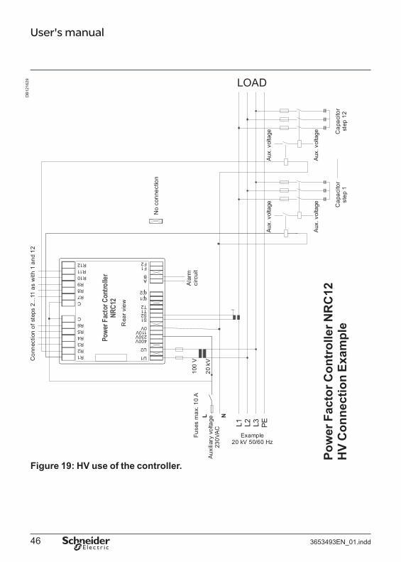
6.3 High voltage application of NRC12 CAUTION: In case of installation in a HV bank (with VT), you must adjust the default
factory settings. The reconnection delay must be changed to a larger value (e.g. 600 secs) to prevent destruction of capacitors.
The controller can be used in HV networks, if the following points are taken into account. Connections must employ VT and CT with respect to the fi gure 19.
The application menu has two voltage ranges for HV applications: 0.5 - 50 kV and 10 - 400 kV. The lower voltage range has finer VT ratio resolution and range than the higher voltage range.
Safety (or reconnection) delay must be adapted to the value of the discharge resistors of the capacitors, the most usual value is 600 seconds (10 minutes). The controller’s default reconnection delay is adapted for LV use. Using too short a reconnection delay may damage the capacitors.
Important:
@@
the whole commissioning process must be performed using the Parameter menu. the commissioner should not use Bank Pre-Configuration, Manual Setup and
Commissioning menus. the use of Auto Setup menu is strictly forbidden to prevent capacitor destruction. do not use "Verify" or "Auto Seek" on HV network applications!
@@
3653493EN_01.indd 45
User's manual
Pow
er F
acto
r Con
trol
ler N
RC
12H
V C
onne
ctio
n Ex
ampl
e
DB
1216
29
Figure 19: HV use of the controller.
3653493EN_01.indd 46
User's manual
7. Options 7.1 External Temperature Sensor The controller has terminals T1/T2 for external temperature sensor. With the external temperature probe the temperature in a critical point in a capacitor bank can be monitored with the controller. The external temperature measurement overrides the internal temperature in fan and alarm monitoring. The External Temperature Sensor can be purchased as an option and installed into the capacitor bank.
Do not touch the connectors when the controller is energized, make sure that the operating voltage is disconnected before touching any parts located on the rear side of the controller.
7.2 Controller Communication AdapterThe controller is equipped with a communication port to connect the controller to a remote master. The communication connector is covered to ensure electrical safety during the operation of the controller. The Controller Communication Adapter (CCA01) can be purchased as an option and is installed into the controller according to installation instructions supplied with the CCA-01.
Always switch off the power from the controller before installation. Make sure that the communication connector is always covered, either with CCA-01 adapter or the original cover before switching on the power. Touching an uncovered connector with the power applied may lead to an electrical shock.
3653493EN_01.indd 47
User's manual
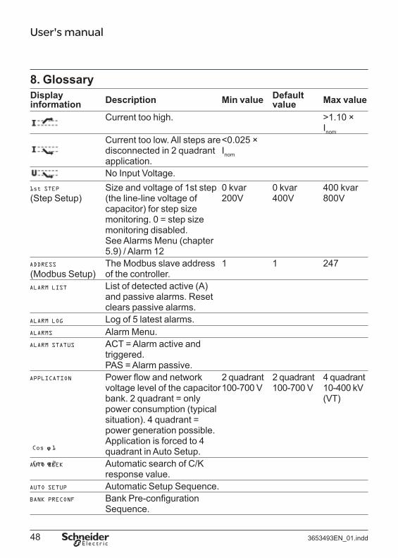
8. Glossary Displayinformation Description Min value Default
value Max value
Current too high. >1.10 × Inom
Current too low. All steps are disconnected in 2 quadrant application.
<0.025 × I nom
No Input Voltage. Size and voltage of 1st step 0 kvar 0 kvar 400 kvar
(Step Setup) (the line-line voltage of 200V 400V 800V capacitor) for step size monitoring. 0 = step size monitoring disabled. See Alarms Menu (chapter 5.9) / Alarm 12 The Modbus slave address 1 1 247
(Modbus Setup) of the controller. List of detected active (A) and passive alarms. Reset clears passive alarms. Log of 5 latest alarms.Alarm Menu.ACT = Alarm active and triggered. PAS = Alarm passive. Power flow and network voltage level of the capacitor bank. 2 quadrant = only power consumption (typical situation). 4 quadrant = power generation possible. Application is forced to 4 quadrant in Auto Setup.
2 quadrant 100-700 V
2 quadrant 100-700 V
4 quadrant 10-400 kV (VT)
Automatic search of C/K response value. Automatic Setup Sequence. Bank Pre-configuration Sequence.
3653493EN_01.indd 48

User's manual
Display Default information Description Min value value Max value
Bank Test: each step is automatically connected and disconnected in turn. This facilitates testing of the operation of each capacitor step contactor. To be used only for testing offline capacitors! Do not use in HV network applications! See also Step Test. Data transmission speed of 1200 9600 38400
(Modbus Setup) the controller. Response value for the capacitive side of the target cos ϕ. Normally set up automatically by the controller. Detected in Auto Setup and Auto seek, or manually if wanted. Checked with verify function.
See "C/K". (Resp Values)
The controller has a connector for CCA communication module (option). Circular stepping program for sequence 1.1.1.1.1.1 Circular stepping program for sequence 1.2.2.2.2.2 Response value. Can be 0.01 0.50 1.99 manually set up or automatically searched by the controller. Clear Statistics. Clear Alarm Log. Commissioning Sequence. Target cos ϕ value 1 0.8 ind 1.00 0.9 cap
(Target cos ϕ) (normally used)
3653493EN_01.indd 49
User's manual
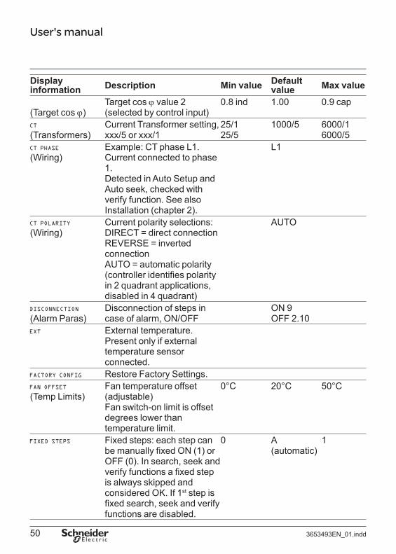
Displayinformation Description Min value Default
value Max value
Target cos ϕ value 2 0.8 ind 1.00 0.9 cap (Target cos ϕ) (selected by control input)
Current Transformer setting, 25/1 1000/5 6000/1 (Transformers) xxx/5 or xxx/1 25/5 6000/5
Example: CT phase L1. Current connected to phase 1. Detected in Auto Setup and Auto seek, checked with verify function. See also Installation (chapter 2).
L1 (Wiring)
Current polarity selections: DIRECT = direct connection REVERSE = inverted connection AUTO = automatic polarity (controller identifi es polarity in 2 quadrant applications, disabled in 4 quadrant)
AUTO (Wiring)
(Alarm Paras) Disconnection of steps in case of alarm, ON/OFF
ON 9 OFF 2.10
External temperature. Present only if external temperature sensor connected. Restore Factory Settings.
(Temp Limits) Fan temperature offset (adjustable) Fan switch-on limit is offset
0°C 20°C 50°C
degrees lower than temperature limit. Fixed steps: each step can 0 A 1 be manually fixed ON (1) or (automatic) OFF (0). In search, seek and verify functions a fi xed step is always skipped and considered OK. If 1st step is fixed search, seek and verify functions are disabled.
3653493EN_01.indd 50

User's manual
Display Default information Description Min value value Max value
Response value for the inductive side of the target cos ϕ. Normally set up automatically by the controller. Detected in Auto Setup and Auto seek, or manually if wanted. Checked with verify function.
See "C/K". (Resp Values)
Nominal input voltage 80V 400V 800Vreference value at input voltage terminals U1 and U2. For voltage alarms.Internal temperature.Capacitor overload factor.Language Selection for Englishmenus.Adjustable over temperature20 °C 50 °C 60 °C
(Alarm 9 Para) alarm limit. Fan switches ON some degrees under this (adjustable offset). Maximum harmonic 5% 7% 20%
(Alarm 10 Para) distortion of voltage (adjustable) Capacity overload alarm 1.0 1.5 1.5
(Alarm 11 Para) limit (maximum Irms/I1 - value) Line to Line connection. Line to Neutral connection. Maintenance Menu (for experts)Manual Setup Sequence.Measurements Menu.Alarm setup (enable /
(Alarm Paras) disable)
3653493EN_01.indd 51

User's manual
Display Default information Description Min value value Max value
The use of controller's (Modbus Setup) communication.
NONE = Communication disabled READ = Communication reads information READ/RESET = Communication reads information and resets alarms. READ/WRITE = Communication reads and writes information
NONE
Number of used steps. 1 12 12 (Step Setup) Detected in Auto Setup,
checked with verify function. Normal stepping program for sequence 1.2.4.4.4.4 Optimal stepping program, for many step sequencies. Parameters Menu. Nominal network voltage in
(Input Voltage) HV applications. Calculated form secondary voltage and VT ratio. Software version.
(Controller Info)
3653493EN_01.indd 52

User's manual
Displayinformation Description Min value Default
value Max value
(Delays) Reconnection delay and response delay. Reconnection delay is used to protect the step capacitors (don't use too short values). Response delay, the minimum time between changes in steps, is defined as 20% of
10s 50s 900s
reconnection delay, min 10 s. The default value corresponds to capacitors with internal discharge resistors 50V 1 min. Response to multi-step changes is faster when using Optimal step program. Search (response value, step sizes and wiring)
(Input Voltage) Controller input voltage in HV applications.
80V 150V
Serial Number of the (Controller Info) product (for internal
manufacturer use) Linear stepping program for sequence 1.1.1.1.1.1
(Modbus Setup) 2 digits containing correct message total counter + 2 digits containing faulty message counter + 2 digits containing replied message counter.
3653493EN_01.indd 53

User's manual
Display Default information Description Min value value Max value
Selection of suitable stepping program between (see 6.1 Stepping programs). Stack Normal Circular 1.1.1 Circular 1.2.2 OptimalForced to Optimal in Auto Setup.
Normal
(Step Setup) Step Sequence setting defines step size ratios starting from the smallest first step. Detected in Auto Setup, checked with verify function. The alternatives are: 1.1.1.1.1.1 - 1.1.2.2.2.2 -1.1.2.3.3.3 - 1.1.2.4.4.4 -1.2.2.2.2.2 - 1.2.3.3.3.3 -1.2.3.4.4.4 - 1.2.3.6.6.6 - 1.2.4.4.4.4 -1.2.4.8.8.8 Step sequence setting is used with optimal stepping program, or if the step size monitoring is on. Step sequence is predefi ned with other programs and modification request are not then taken into account
1.1.1.1.1.1 1.1.1.1.1.1 1.2.4.8.8.8
3653493EN_01.indd 54

User's manual
Display Default information Description Min value value Max value
Step Test: each step can be manually connected and disconnected. This facilitates testing of the operation of each capacitor step contactor. See also Bank Test. Number of step connections and usage hours. Total Harmonic Distortion of Current. Total Harmonic Distortion of Voltage Contains CT setup, and VT setup in HV applications. Uptime (Power On Hours)
(Controller Info) Automatic verifi cation of parameters. Checks C/K value, steps and wiring. In case of an error refer to error table, page 20. Do not use on HV network applications! Voltage Transformer ratio 1.0 1.0 625.0
(Transformers) setting. 60 4000 0.5 – 50 kV
10 – 400 kV
(Wiring) Connections of voltage L2-L3 inputs. Example: Voltage phase L2L3 (Voltage connected between phase 2 and 3) Detected in Auto Setup and Auto seek, checked with verify function. See also Installation (chapter 2).
3653493EN_01.indd 55

User's manual
9. Technical specifications Number of steps 12 Dimensions 155 x 158 x 80 mm Frequency 50 Hz nominal (range 48...52 Hz)
60 Hz nominal (range 58...62 Hz) Measuring current 0…1 A or 0...5 A Measuring voltage 80…690 V (nominal, max. 115%) Displayed measuring power 100000 kVA Nominal power consumption 13 VA Supply voltages 110 V nominal, (range 88...130 V)
230 V nominal, (range 185...265 V)400 V nominal, (range 320...460 V)
Relay inputs/outputs 250 V, 2 A Display Dot matrix display, resolution 64x128 pixels, backlighted. Protection class IP41 front panel, IP20 rear part. Target cos ϕ -range 0.85 ind …1.00 … 0.90 cap Response limits 0.01 … 1.99, symmetrical or asymmetrical Reconnection delay 10…900 s Response delay 20 % of reconnection delay, min. 10 s Displayed measurements cos ϕ, Iact, Ireact, Iapp, IRMS/I1, P, Q, S, THD (U) and voltage
harmonics, THD(I) and current harmonics, internal and external temperature.
Installation method Panel installation, DIN-rail installation. Casing Impact resistant PC/ABS, UL94V-0 Operating temperature range 0…60°C Alarm log List of 5 last alarms. Step counters Yes Fan control with dedicated relay Yes. 250 V AC, 8A Alarm relay Yes. 250 V AC, 8A Accuracy (of FS) I: 2%
IQ: 2%U/I-samples: 2%Phase: 1°Distortion: ±3 dB (up to 15th)Internal temperature: ±3°CExternal temperature: ±2°C (option)
CT setting range 25/1 … 6000/1 or 25/5 … 6000/5 Power outage detection Reaction time > 15 ms Standards IEC 61010-1
IEC 61000-6-2 IEC 61000-6-4 UL 61010A-1 IEC 60529
Communication Modbus protocol using CCA-01 (option)
Schneider Electric Industries SAS Rectiphase399 rue de la Gare 74370 PringyFrance Tel.: 33 (0)4 50 66 95 00Fax: 33 (0)4 50 27 24 19http://www.schneider-electric.comhttp://www.merlin-gerin.com
N° 3653493EN_01
As standards, specifications and designs change from time totime, please ask for confirmation of the information given in thispublication.
Printed on ecological paper. Layout: Schneider Electric - SedocPhotos: Schneider Electric Printing:
04-2009
© 2
009
- Sch
neid
er E
lect
ric -
All
right
s re
serv
ed.