Embed Size (px)
Citation preview

VASIMR R© Technological Advances and
First Stage Performance Results
Leonard D. Cassady∗, William J. Chancery†, Ben W. Longmier†, Chris Olsen‡,
Greg McCaskill§, Mark Carter¶, Tim W. Glover‖, Jared P. Squire∗∗,
and Franklin R. Chang Diaz††
Ad Astra Rocket Company, 141 W. Bay Area Blvd, Houston, TX 77598, USA
Edgar A. Bering, III‡‡
University of Houston, Department of Physics, Houston, TX, 77204,USA
A 200 kW VASIMR R© engine designed specifically to demonstrate the end-to-end DCelectrical power conversion to thrust power has undergone initial testing in a new vac-uum facility and successfully operated with a low temperature superconducting magnet,two solid-state RF generators, and improved RF coupler designs. This engine is giventhe name VX-200 for a VASIMR R© experimental device that operates at 200 kW inputelectrical power. The VX-200 has shown through its successful operation that the primarytechnologies required for a spaceflight version of the VASIMR R© are compatible with eachother and can operate at practical efficiencies. The first stage, or helicon section, of theengine has operated at full power with maximum magnetic field. The second stage, orbooster, has operated at nearly full power with a lower magnetic field. Ion flux measure-ments were taken in a new 150 m3 vacuum chamber with 100,000 liters/second of pumpingthat contained the VX-200. The first stage generated an argon plasma jet with a cost toextract an electron-ion pair of 78 ± 11 eV/ion at 32 kW and a flow rate of 135 mg/s. Arecord power of 149.2 kW was coupled to the plasma with the booster RF coupler.
I. Introduction
High-power electric propulsion systems have the capability of reducing the propellant mass for heavy-payload orbit raising missions and cargo missions to the moon and can even reduce the trip time of pilotedplanetary missions.1–5 The Variable Specific Impulse Magnetoplasma Rocket (VASIMR R©), is one of the fewelectric propulsion devices capable of processing a great amount of power (>100 kW) with a long lifetime.A simplified concept is shown in figure 1. The advantages of the VASIMR R© are high power, high specificimpulse, and potentially long lifetime due to the magnetic control of the plasma stream. The rocket relieson efficient plasma production in the first stage using a helicon plasma source.6,7 Ion cyclotron resonanceenables efficient ion energy boost in the second stage (RF booster). Thrust is realized in the final stage asthe plasma accelerates in a magnetic nozzle. End-to-end testing of the VASIMR R© with spaceflight relevantcomponents, the optimum magnetic field configuration, and a vacuum facility large enough and with enoughpumping to allow for plume measurements with low background pressure had not been achieved until recently.The VX-200 operating in a new, large vacuum facility have demonstrated that the VASIMR R© does operateas a system and efficiently produces plasma.∗Lead Project Engineer and AIAA Member†Research Scientist and AIAA Member‡Research Associate§Senior RF Engineer¶Director of Technology‖Director of Development∗∗Director of Research††President and CEO‡‡Professor, Physics and ECE, 617 Science & Research Bldg 1, Associate Fellow
1 of 9
American Institute of Aeronautics and Astronautics
45th AIAA/ASME/SAE/ASEE Joint Propulsion Conference & Exhibit2 - 5 August 2009, Denver, Colorado
AIAA 2009-5362
Copyright © 2009 by Leonard Cassady. Published by the American Institute of Aeronautics and Astronautics, Inc., with permission.
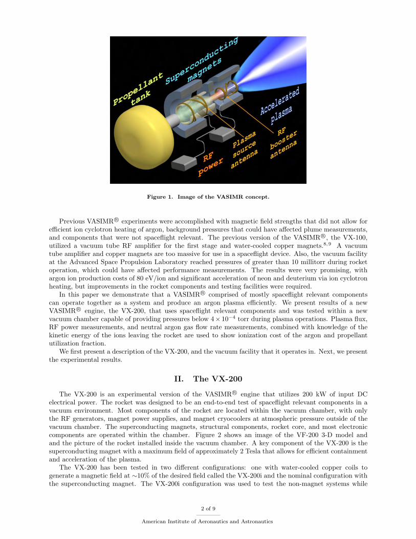
Figure 1. Image of the VASIMR concept.
Previous VASIMR R© experiments were accomplished with magnetic field strengths that did not allow forefficient ion cyclotron heating of argon, background pressures that could have affected plume measurements,and components that were not spaceflight relevant. The previous version of the VASIMR R©, the VX-100,utilized a vacuum tube RF amplifier for the first stage and water-cooled copper magnets.8,9 A vacuumtube amplifier and copper magnets are too massive for use in a spaceflight device. Also, the vacuum facilityat the Advanced Space Propulsion Laboratory reached pressures of greater than 10 millitorr during rocketoperation, which could have affected performance measurements. The results were very promising, withargon ion production costs of 80 eV/ion and significant acceleration of neon and deuterium via ion cyclotronheating, but improvements in the rocket components and testing facilities were required.
In this paper we demonstrate that a VASIMR R© comprised of mostly spaceflight relevant componentscan operate together as a system and produce an argon plasma efficiently. We present results of a newVASIMR R© engine, the VX-200, that uses spaceflight relevant components and was tested within a newvacuum chamber capable of providing pressures below 4× 10⁻⁴ torr during plasma operations. Plasma flux,RF power measurements, and neutral argon gas flow rate measurements, combined with knowledge of thekinetic energy of the ions leaving the rocket are used to show ionization cost of the argon and propellantutilization fraction.
We first present a description of the VX-200, and the vacuum facility that it operates in. Next, we presentthe experimental results.
II. The VX-200
The VX-200 is an experimental version of the VASIMR R© engine that utilizes 200 kW of input DCelectrical power. The rocket was designed to be an end-to-end test of spaceflight relevant components in avacuum environment. Most components of the rocket are located within the vacuum chamber, with onlythe RF generators, magnet power supplies, and magnet cryocoolers at atmospheric pressure outside of thevacuum chamber. The superconducting magnets, structural components, rocket core, and most electroniccomponents are operated within the chamber. Figure 2 shows an image of the VF-200 3-D model andand the picture of the rocket installed inside the vacuum chamber. A key component of the VX-200 is thesuperconducting magnet with a maximum field of approximately 2 Tesla that allows for efficient containmentand acceleration of the plasma.
The VX-200 has been tested in two different configurations: one with water-cooled copper coils togenerate a magnetic field at ∼10% of the desired field called the VX-200i and the nominal configuration withthe superconducting magnet. The VX-200i configuration was used to test the non-magnet systems while
2 of 9
American Institute of Aeronautics and Astronautics
(a) Image of simplified 3-D model of the VX-200 with apoint of view from the aft end.
(b) Picture of VX-200 installed in the large chamber atAd Astra Rocket Company.
Figure 2. The VX-200.
waiting for delivery of the superconducting magnet, including the solid-state RF generators, control system,propellant feed system, and sensors with the water-cooled magnet.
The VX-200 can operate in a long-pulse (up to 1 minute) mode in the current configuration due totemperature limitations of certain seals and joints. We will use the thermal data gathered from the pulsedoperation to design the optimal thermal solution for the actual heat flux. Most VX-200 pulses are between8 and 15 seconds in length.
The first stage, or helicon stage, launches a right-hand circularly polarized wave into the plasma. Theplasma diameter is reduced by more than a factor of 2 as it flows downstream through a “magnetic choke”and containment wall that follows the plasma flux tube. Up to 40 kW of RF power (RF generator limited)can be deposited into up to 150 mg/s of flowing argon plasma. The second stage, or Ion Cyclotron Heating(ICH) stage, deposits energy directly into the ions via ion cyclotron resonance interaction of an ion cyclotronwave that is launched into the plasma via a specially designed, proprietary coupler. The exhaust velocity ofthe ions increases as the RF power is coupled into the ICH section increases.
The primary components are the control computer, propellant flow controller, RF generators, and magnet.The rocket is controlled by an Aitech Inc. E900 chassis mounted on the VX-200 inside the chamber. Argongas flow control is provided by a Moog flow controller that can supply up to 150 mg/s. The other twocomponents are described in the following subsections.
A. RF Generators
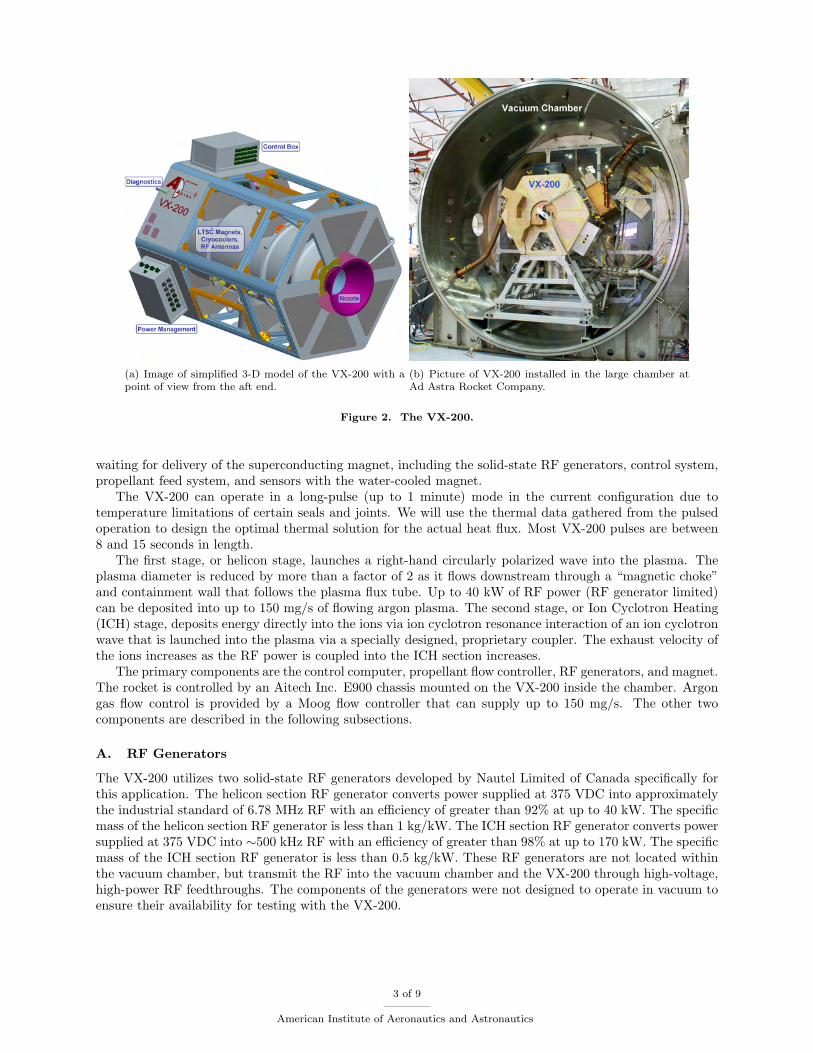
The VX-200 utilizes two solid-state RF generators developed by Nautel Limited of Canada specifically forthis application. The helicon section RF generator converts power supplied at 375 VDC into approximatelythe industrial standard of 6.78 MHz RF with an efficiency of greater than 92% at up to 40 kW. The specificmass of the helicon section RF generator is less than 1 kg/kW. The ICH section RF generator converts powersupplied at 375 VDC into ∼500 kHz RF with an efficiency of greater than 98% at up to 170 kW. The specificmass of the ICH section RF generator is less than 0.5 kg/kW. These RF generators are not located withinthe vacuum chamber, but transmit the RF into the vacuum chamber and the VX-200 through high-voltage,high-power RF feedthroughs. The components of the generators were not designed to operate in vacuum toensure their availability for testing with the VX-200.
3 of 9
American Institute of Aeronautics and Astronautics
Figure 3. Picture of ICH RF generator and the helicon RF generator.
B. Low Temperature Superconducting Magnet
The VASIMR R© relies on magnetic fields to limit plasma contact with the surrounding materials as well asto provide the field strength necessary for ion cyclotron resonance at a frequency that does not excessivelyexcite electrons and limits the cyclotron radius. The gyro radius should be much less than the plasma radius,which corresponds to a field strength of greater than 1 T. In order to have an efficient electric propulsiondevice, the magnet must consume a small amount of power compared to thrust power. The only feasiblemethod to generate such a strong magnetic field in space is with a superconducting magnet. The VX-200is utilizing a state-of-the-art low temperature superconducting magnet designed and developed by ScientificMagnetics, LLC of the United Kingdom specifically for the VX-200. The magnet is shown in figure 4. Thespaceflight VASIMR R© will utilize a high temperature superconducting magnet so that the heat-rejectionsystems that chill the magnet can operate with a high efficiency.
III. Vacuum Facility
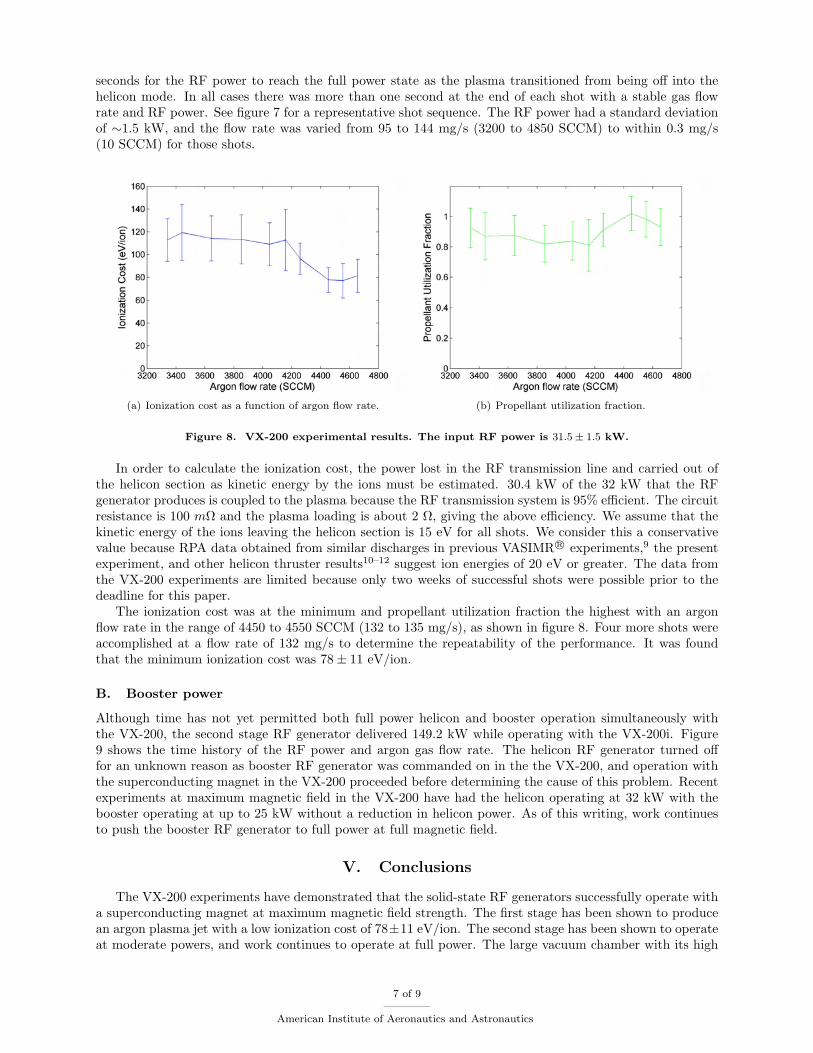
Ad Astra Rocket Company has a new stainless steel vacuum chamber (see figure 5) that was designed fortesting the VASIMR R© engine. The vacuum chamber is 4.2 m in diameter and 10 m long with a volume of150 m3 (including the end caps). One end opens fully for access to the entire inner diameter. The vacuumchamber is partitioned into two sections, a rocket section and an exhaust section. The rocket section staysat a lower pressure than the exhaust section while the VX-200i is firing. This is done to prevent arcingand glow discharges near the high voltage transmission lines and matching circuit components. There is a2.5 m by 5 m translation stage that carries a suite of plasma diagnostics for plume characterization. Thetranslation stage uses 2 independent ball screws and is driven by vacuum compatible stepper motors whichyield a positional resolution of 0.5 mm. The facility has the capability of pumping 200,000 liters/s Argon and300,000 liters/s Nitrogen with four PHPK Technologies CVI Torr Master R© internal cryopumps. Presently,only two pumps are being operated which reduces the pumping speeds by a factor of two, but allows foradequate pressures to take experimental measurements of first stage performance. The pressure is less than1× 10−7 torr before each shot. The pressure rises to a maximum of 4× 10⁻⁴ torr during a shot.
4 of 9
American Institute of Aeronautics and Astronautics
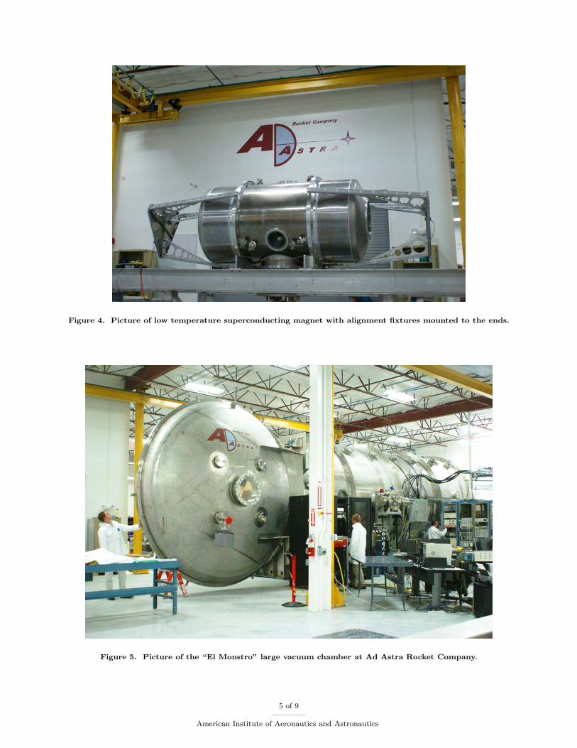
Figure 4. Picture of low temperature superconducting magnet with alignment fixtures mounted to the ends.
Figure 5. Picture of the “El Monstro” large vacuum chamber at Ad Astra Rocket Company.
5 of 9
American Institute of Aeronautics and Astronautics

IV. Results
The results from the first experimental campaign of the VX-200 operating at maximum magnetic fieldswill be presented in this section. The performance of the system is expected to improve as experience isgained with the solid-state RF generators at high powers coupling to plasmas with high magnetic fields.Figure 6 shows a picture of the VX-200 plume.
Figure 6. Picture of VX-200 plasma plume.
Figure 7. Helicon RF power and argon flow rate as a function of time throughout a shot.
A. Gas Flow Rate Scan
To determine the minimum ionization cost, a set of experiments were conducted where the helicon RF powerwas set to 32 kW and the propellant flow rate was varied. The plasma flux was measured just downstream ofthe rocket using an array of planar Langmuir probes. The helicon RF generator was commanded to deliver32 kW of power for the final seconds (4 to 8 s depending on the conditions) of every shot. It took up to 4
6 of 9
American Institute of Aeronautics and Astronautics
seconds for the RF power to reach the full power state as the plasma transitioned from being off into thehelicon mode. In all cases there was more than one second at the end of each shot with a stable gas flowrate and RF power. See figure 7 for a representative shot sequence. The RF power had a standard deviationof ∼1.5 kW, and the flow rate was varied from 95 to 144 mg/s (3200 to 4850 SCCM) to within 0.3 mg/s(10 SCCM) for those shots.
(a) Ionization cost as a function of argon flow rate. (b) Propellant utilization fraction.
Figure 8. VX-200 experimental results. The input RF power is 31.5± 1.5 kW.
In order to calculate the ionization cost, the power lost in the RF transmission line and carried out ofthe helicon section as kinetic energy by the ions must be estimated. 30.4 kW of the 32 kW that the RFgenerator produces is coupled to the plasma because the RF transmission system is 95% efficient. The circuitresistance is 100 mΩ and the plasma loading is about 2 Ω, giving the above efficiency. We assume that thekinetic energy of the ions leaving the helicon section is 15 eV for all shots. We consider this a conservativevalue because RPA data obtained from similar discharges in previous VASIMR R© experiments,9 the presentexperiment, and other helicon thruster results10–12 suggest ion energies of 20 eV or greater. The data fromthe VX-200 experiments are limited because only two weeks of successful shots were possible prior to thedeadline for this paper.
The ionization cost was at the minimum and propellant utilization fraction the highest with an argonflow rate in the range of 4450 to 4550 SCCM (132 to 135 mg/s), as shown in figure 8. Four more shots wereaccomplished at a flow rate of 132 mg/s to determine the repeatability of the performance. It was foundthat the minimum ionization cost was 78± 11 eV/ion.
B. Booster power
Although time has not yet permitted both full power helicon and booster operation simultaneously withthe VX-200, the second stage RF generator delivered 149.2 kW while operating with the VX-200i. Figure9 shows the time history of the RF power and argon gas flow rate. The helicon RF generator turned offfor an unknown reason as booster RF generator was commanded on in the the VX-200, and operation withthe superconducting magnet in the VX-200 proceeded before determining the cause of this problem. Recentexperiments at maximum magnetic field in the VX-200 have had the helicon operating at 32 kW with thebooster operating at up to 25 kW without a reduction in helicon power. As of this writing, work continuesto push the booster RF generator to full power at full magnetic field.
V. Conclusions
The VX-200 experiments have demonstrated that the solid-state RF generators successfully operate witha superconducting magnet at maximum magnetic field strength. The first stage has been shown to producean argon plasma jet with a low ionization cost of 78±11 eV/ion. The second stage has been shown to operateat moderate powers, and work continues to operate at full power. The large vacuum chamber with its high
7 of 9
American Institute of Aeronautics and Astronautics
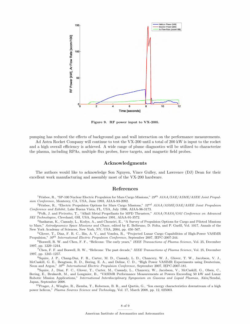
Figure 9. RF power input to VX-200i.
pumping has reduced the effects of background gas and wall interaction on the performance measurements.Ad Astra Rocket Company will continue to test the VX-200 until a total of 200 kW is input to the rocket
and a high overall efficiency is achieved. A wide range of plume diagnostics will be utilized to characterizethe plasma, including RPAs, multiple flux probes, force targets, and magnetic field probes.
Acknowledgments
The authors would like to acknowledge Son Nguyen, Vince Gulley, and Lawrence (DJ) Dean for theirexcellent work manufacturing and assembly most of the VX-200 hardware.
References
1Frisbee, R., “SP-100 Nuclear Electric Propulsion for Mars Cargo Missions,” 29th AIAA/SAE/ASME/ASEE Joint Propul-sion Conference, Monterey, CA, USA, June 1993, AIAA-93-2092.
2Frisbee, R., “Electric Propulsion Options for Mars Cargo Missions,” 32nd AIAA/ASME/SAE/ASEE Joint PropulsionConference and Exhibit , Lake Buena Vista, FL, USA, July 1996, AIAA-96-3173.
3Polk, J. and Pivirotto, T., “Alkali Metal Propellants for MPD Thrusters,” AIAA/NASA/OAI Conference on AdvancedSEI Technologies, Cleveland, OH, USA, September 1991, AIAA-91-3572.
4Sankaran, K., Cassady, L., Kodys, A., and Choueiri, E., “A Survey of Propulsion Options for Cargo and Piloted Missionsto Mars,” Astrodynamics Space Missions and Chaos, edited by E. Belbruno, D. Folta, and P. Gurfil, Vol. 1017, Annals of theNew York Academy of Sciences, New York, NY, USA, 2004, pp. 450–567.
5Glover, T., Diaz, F. R. C., Ilin, A. V., and Vondra, R., “Projected Lunar Cargo Capabilities of High-Power VASIMRPropulsion,” 30th International Electric Propulsion Conference, September 2007, IEPC-2007-244.
6Boswell, R. W. and Chen, F. F., “Helicons: The early years,” IEEE Transactions of Plasma Science, Vol. 25, December1997, pp. 1229–1244.
7Chen, F. F. and Boswell, R. W., “Helicons: The past decade,” IEEE Transactions of Plasma Science, Vol. 25, December1997, pp. 1245–1257.
8Squire, J. P., Chang-Daz, F. R., Carter, M. D., Cassady, L. D., Chancery, W. J., Glover, T. W., Jacobson, V. J.,McCaskill, G. E., Bengtson, R. D., Bering, E. A., and Deline, C. D., “High Power VASIMR Experiments using Deuterium,Neon and Argon,” 30th International Electric Propulsion Conference, September 2007, IEPC-2007-181.
9Squire, J., Diaz, F. C., Glover, T., Carter, M., Cassady, L., Chancery, W., Jacobson, V., McCaskill, G., Olsen, C.,Bering, E., Brukardt, M., and Longmier, B., “VASIMR Performance Measurements at Powers Exceeding 50 kW and LunarRobotic Mission Applications,” International Interdisciplinary Symposium on Gaseous and Liquid Plasmas, Akiu/Sendai,Japan, September 2008.
10Prager, J., Winglee, R., Ziemba, T., Roberson, B. R., and Quetin, G., “Ion energy characteristics downstream of a highpower helicon,” Plasma Sources Science and Technology, Vol. 17, March 2008, pp. 12, 025003.
8 of 9
American Institute of Aeronautics and Astronautics

11Charles, C., Boswell, R. W., Laine, R., and MacLellan, P., “An experimental investigation of alternative propellants forthe helicon double layer thruster,” Journal of Physics D: Applied Physics, Vol. 41, August 2008, pp. 6, 175213.
12Charles, C., “A review of recent laboratory double layer experiments,” Plasma Sources Science and Technology, Vol. 16,September 2007, pp. R1–R25.
9 of 9
American Institute of Aeronautics and Astronautics


![Nautel Offshore NDB Presentation Dec2014€¦ · Microsoft PowerPoint - Nautel Offshore NDB Presentation Dec2014 [Compatibility Mode] Author: Gary Created Date: 5/20/2015 12:31:03](https://img.pdfslide.net/doc/110x75/60004fef3f1440460250c064/nautel-offshore-ndb-presentation-dec2014-microsoft-powerpoint-nautel-offshore.jpg)