Embed Size (px)
Citation preview

USER MANUAL
Vault SeriesTrue On Line, Double Conversion
Uninterruptible Power Supply
For Models 4000VA ~ 12000VA


CONTENTS
1. Introduction............................................................................................................................................52. System Description................................................................................................................................5
2.1 General Description.............................................................................................................................................5
2.2 System Configuration...........................................................................................................................................6
3. Safety Information..................................................................................................................................74. Storage....................................................................................................................................................75. Installation..............................................................................................................................................8
5.1 Environment .........................................................................................................................................................8
5.2 AC Power and Load Connection.....................................................................................................................8 - 9
5.3 Rear Panel Views..........................................................................................................................................10 - 14
5.4 Factory Default Settings .....................................................................................................................................15
6. Computer (Load) Interface and Alarm Connections..........................................................................156.1 Overview............................................................................................................................................................15
6.2 Connecting The UPS To A Load........................................................................................................................15
7. Operational Instructions......................................................................................................................177.1 Starting Up and Shutting Down the UPS............................................................................................................17
7.2 Push-button Operations......................................................................................................................................17
7.3 Control Panel Indicators................................................................................................................................18
7.4 LCD Panel Display Modes ................................................................................................................................19
7.7 Troubleshooting.................................................................................................................................................22
8. Maintenance.........................................................................................................................................238.1 Battery Replacement.........................................................................................................................................23
9. Specifications................................................................................................................................24 - 2510. Warranties..............................................................................................................................................26
1
7.6 Audible Alarms..................................................................................................................................................21
7.5 Manual UPS or Battery Test..............................................................................................................................20
6.7 Load Segments..................................................................................................................................................16
6.6 Network Transient Protector...............................................................................................................................16
6.5 EPO (Emergency Power Off) Port.....................................................................................................................16
6.4 USB Port.............................................................................................................................................................16
6.3 RS-232 Interface Port.........................................................................................................................................16
EMC Statements Declaration of Conformity Request Units labeled with a CE mark comply with the following standards and directives: 1. Harmonic Standards: EN 50091-1-1 and EN 50091-2 2. EU Directives: 73/23/EEC, Council Directive on equipment designed for use within certain voltage
limits.
93/68/EEC, Amending Directive 73/23/EEC
89/336/EEC, Council Directive relating to electromagnetic compatibility
92/31/EEC, Amending Directive 89/336/EEC relating to EMC
The EC Declaration of Conformity is available upon request for products with a CE mark.
2
CISPR 22 NOTICE: Pursuant to CISPR 22 rules, this product has been tested and thereby complies with the conditions of a Class A digital device, which have been established for offering sufficient protection against dangerous interference for installation in a residential area. Installation and use of the equipment should comply with the instructions provided in order to avoid such interference due to the amount of radio frequency energy that is radiated and generated by the equipment. In spite of this, we cannot assure that a certain amount of interference may not occur in some installations. If, by turning on and off, it can be deduced that your radio or television reception is found to be influenced by harmful interference from the equipment, it is recommended to use one of the following preventive measures:
Place the receiving antenna in a separate location or orientation. Ensure a greater distance is achieved between the receiver and the equipment. Ensure that your equipment is connected to an outlet on a separate circuit than the receiver. Contact a technician experienced with radio and TV or a dealer for further assistance.
IMPORTANT SAFETY INSTRUCTIONS SAVE THESE INSTRUCTIONS
1. CAUTION (UPS with Internal Batteries): Risk of electric shock - Hazardous live parts
inside this unit are energized from the battery supply even when the input AC power is disconnected.
2. CAUTION (No User Serviceable Parts): Risk of electric shock, do not remove cover. No user serviceable parts inside. Refer servicing to qualified service personnel.
3. CAUTION (Non-isolated Battery supply): Risk of electric shock, battery circuit is not isolated from AC input, hazardous voltage may exist between battery terminals and ground. Test before touching.
4. WARNING (Fuses): To reduce the risk of fire, replace only with the same type and rating of fuse.
5. WARNING: Intended for installation in a controlled environment. 6. CAUTION: Do not dispose of batteries in a fire, as they may explode. 7. CAUTION: Do not open or damage the battery, electrolyte may be released which is
harmful to the skin and eyes. 8. CAUTION: A battery can present a risk of electric shock and high short circuit current.
The following precautions should be taken when working with batteries: a. Remove watches, rings and other jewelry or metal objects. b. Use tools with insulated handles.
9. To reduce the risk of electric shock, disconnect the UPS from the AC input power supply before installing a communication interface cable. Reconnect the power cord only after communication interconnections have been made.
10. Battery replacement should be performed or supervised by personnel with knowledge of batteries. Keep unauthorized personnel away from the batteries.
3
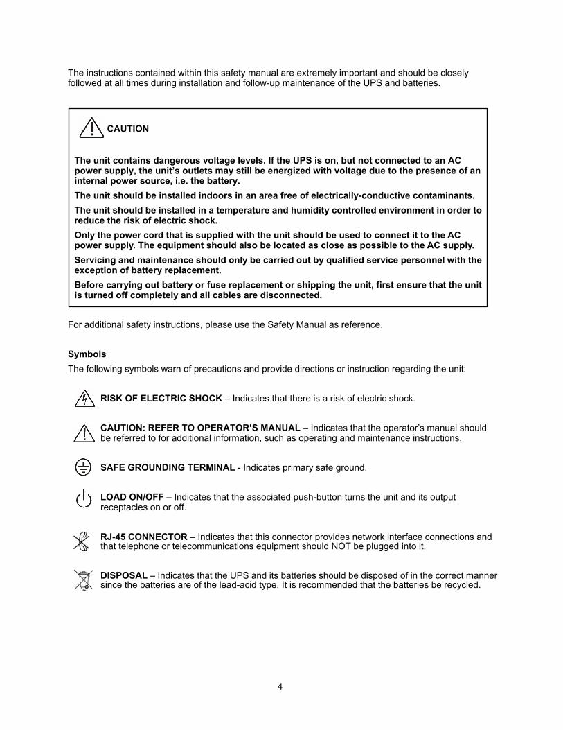
The instructions contained within this safety manual are extremely important and should be closely followed at all times during installation and follow-up maintenance of the UPS and batteries.
CAUTION
The unit contains dangerous voltage levels. If the UPS is on, but not connected to an AC power supply, the unit’s outlets may still be energized with voltage due to the presence of an internal power source, i.e. the battery. The unit should be installed indoors in an area free of electrically-conductive contaminants. The unit should be installed in a temperature and humidity controlled environment in order to reduce the risk of electric shock. Only the power cord that is supplied with the unit should be used to connect it to the AC power supply. The equipment should also be located as close as possible to the AC supply. Servicing and maintenance should only be carried out by qualified service personnel with the exception of battery replacement. Before carrying out battery or fuse replacement or shipping the unit, first ensure that the unit is turned off completely and all cables are disconnected.
For additional safety instructions, please use the Safety Manual as reference. Symbols The following symbols warn of precautions and provide directions or instruction regarding the unit:
RISK OF ELECTRIC SHOCK – Indicates that there is a risk of electric shock. CAUTION: REFER TO OPERATOR’S MANUAL – Indicates that the operator’s manual should be referred to for additional information, such as operating and maintenance instructions. SAFE GROUNDING TERMINAL - Indicates primary safe ground. LOAD ON/OFF – Indicates that the associated push-button turns the unit and its output receptacles on or off. RJ-45 CONNECTOR – Indicates that this connector provides network interface connections and that telephone or telecommunications equipment should NOT be plugged into it. DISPOSAL – Indicates that the UPS and its batteries should be disposed of in the correct manner since the batteries are of the lead-acid type. It is recommended that the batteries be recycled.
4
1. Introduction The information provided in this manual refers to our single phase, 4000VA through 12000VA, true on-line uninterruptible power supplies. It covers basic functions, operating and installation instructions, cautionary notes and detail on how to ship, store and handle them. Installation must be carried out in accordance with this manual as well as local electrical regulations and should only be performed by qualified personnel to avoid the risk of electric shock or damage to the unit. Any warranties covering these units will become void if the unit is found to have been incorrectly connected or tampered with.
2. System Description
2.1 General description
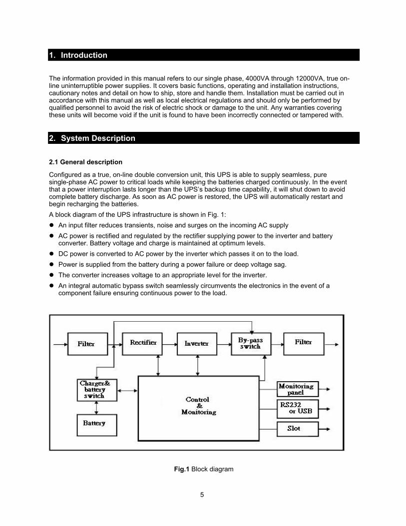
Configured as a true, on-line double conversion unit, this UPS is able to supply seamless, pure single-phase AC power to critical loads while keeping the batteries charged continuously. In the event that a power interruption lasts longer than the UPS’s backup time capability, it will shut down to avoid complete battery discharge. As soon as AC power is restored, the UPS will automatically restart and begin recharging the batteries. A block diagram of the UPS infrastructure is shown in Fig. 1:
An input filter reduces transients, noise and surges on the incoming AC supply AC power is rectified and regulated by the rectifier supplying power to the inverter and battery
converter. Battery voltage and charge is maintained at optimum levels. DC power is converted to AC power by the inverter which passes it on to the load. Power is supplied from the battery during a power failure or deep voltage sag. The converter increases voltage to an appropriate level for the inverter. An integral automatic bypass switch seamlessly circumvents the electronics in the event of a
component failure ensuring continuous power to the load.
Fig.1 Block diagram
5
Efficiency Optimizer
The Efficiency Optimizer is a unique feature that reduces long-term cost of ownership by minimizing power loss and reducing power consumption thereby making the entire system extremely efficient. Simply put, the UPS automatically alternates between bypass and on-line modes depending upon the condition of the incoming AC power. The UPS will remain in on-line mode during any type of power disturbance but unlike traditional on-line systems, will switch to bypass mode when AC power is within acceptable limits in order to achieve greatest efficiency. Power disturbances can be detected in less than a second, and on-line mode reactivated immediately. Switching back to online mode occurs when the input voltage is outside of ±10% of nominal (±15% selectable), when input frequency is outside of ±3Hz or when no AC power is present. While the default operation is on-line mode, bypass can be activated via the LCD panel. The Efficiency Optimizer can be de-activated and the unit can be run permanently in on-line mode if preferred.
Free Run Mode
Free run mode is defined as being when the output frequency is fixed and not synchronized with the input frequency. When activated, the output frequency regulation is automatically set to either 50 or 60 Hz and is regulated to within within ±0.25Hz. Please refer to Chapter 7 for instructions on how to activate bypass mode while the UPS is in free run mode.
Diagnostic tests
Whenever the UPS turned on, a diagnostic test to check the status of the internal electronics and battery is activated. Any errors or faults are displayed on the LCD panel. An advanced battery management system continuously monitors the condition of the batteries and notifies the user in advance if replacement is needed. In addition, a battery discharge test is performed every 30 days in normal mode operation, and any problems are displayed on the LCD panel. Diagnostic tests can be performed manually from the LCD panel at any time, except during the first 24 hours after startup while the UPS is in charging mode (see Chapter 7).
2.2 System Configuration and Sizing
The internal electronics of the UPS plus the internal battery or batteries constitute the system. Please make sure that the following factors have been taken into consideration: 1. The total demand of the protected load determines the UPS power (VA) requirements. Allow some
margin or headroom for future expansion or power requirement calculation inaccuracies. 2. Aside from power (VA) requirements, backup time needs to be considered. If the power consumed
by the load is less than the nominal power rating of the UPS, then the actual backup time will be longer.
3. The following options are available, depending on application and load requirements: a. External Battery Packs (EBP’s) for extended run-times b. Input/Output transformer cabinets c. Maintenance bypass switches d. Connectivity and control options (e.g. relay card, SNMP/WEB card)
6
3. Safety Information PLEASE READ THIS SECTION TO AVOID RISK OF SHOCK OR OTHER HAZARDOUS SITUATIONS. 1. Please handle the unit with extreme caution since the batteries contain large amounts of energy.
Always store the unit in the orientation marked on the packaging. 2. Take extra care to avoid dropping the unit. 3. If flammable substances are present or if any gases or fumes are being emitted or if there is no
ventilation in the place of storage or installation, a safety hazard exists and neither the unit or the extended battery packs should be operated in these environments.
4. The instructions in this manual detail how to install the UPS safely and correctly. Please read it thoroughly and keep this manual for future reference.
WARNING! It is strongly advised that the UPS NOT be opened by anyone other than suitably qualified personnel. Dangerously high voltages are present within, regardless of whether the UPS is connected or not. In addition, the unit’s output receptacles may contain live AC voltage even when not connected to the AC power supply since it contains its own energy source, (i.e. batteries).
User Allowable Operations
The only UPS-related operations that the user is allowed to perform are: 1. Turning the unit on and off. 2. Operating the user interface (function push-buttons and LCD panel). 3. Connecting data interface cables 4. Changing the batteries All such operations are to be performed exactly as instructed in this manual. Any deviation from these instructions may prove hazardous and even fatal or may cause damage to the unit.
4. Storage Please adhere to the following storage instructions if the UPS is not to be installed shortly after delivery: 1. Store the unit as is in its original packing and shipping container. 2. Store the unit within the following temperature range: 5°F to 122°F (-5°C to +50°C). 3. Ensure that the equipment is fully protected from wet or damp areas and from moisture. 4. Ensure that the UPS is recharged every 6 months for at least 8 hours in order to maintain battery
energy and maximize useable life.
7
5. Installation
5.1 Environment
Ensure that all environmental requirements are met, otherwise the safety of installation personnel and users cannot be guaranteed. In addition, the unit may sustain damage or malfunction.
Please adhere to the following environmental instructions when locating the UPS and EBP’s: 1. Avoid temperature and humidity extremes. The optimum operating temperature range is between
59°F and 77°F (+15°C and +25°C). 2. Provide protection against moisture or avoid altogether if possible. 3. Ensure there is at least 4 inches (100mm) behind and 2 inches (50mm) on each side of the UPS for
ventilation. 4. Ensure that the front of the UPS remains unobstructed for access to the control panel and LCD
display. 5. External Battery Packs must be installed next to or under the UPS.
8
5.2 AC Power and Load Connections
Various input (and sometimes output) cables are supplied with all models: 1. Ensure that the UPS is disconnected from the AC supply when connecting External Battery Packs.2. Use the battery cable that is supplied with the External Battery Pack when connecting it to the UPS.
Connect the second battery cabinet to the first and so forth, assuming more than one is to be used.3. Take note of UPS parameters when adding external battery packs and adjust accordingly (see Ch. 7).4. Connect the input cable to the UPS and connect the other end to a grounded AC power supply. The
batteries will automatically begin to charge. Please note that while the UPS may be used immediately, maximum back-up time may not be available until the batteries have been charged for a minimum of 8 hours.
5. If the unit displays “Site Wiring Fault”, have the wiring fault corrected or alternately, disable the related alarm on the UPS.
6. After initial charging is complete, connect the loads to the UPS (see Figs below). 7. Do not connect any load that may overload the UPS such as equipment containing AC electric
motors or loads that have a high inrush current. 8. Make computer and/or alarm interface connections according to Chapter 6 of this user manual and
that provided with the interface option. These connections are made on the rear panel. 9. Installation is now complete.
Only qualified technicians should carry out installation of this equipment. The installation must further comply with all local legislation and regulations.
Follow all installation and safety instructions very carefully to avoid the existence of a hazardous situation and damage to the UPS and/or loads. The high voltage and current contained within this equipment can injure or be fatal to personnel and can damage associated equipment.
Additional Installation Information (for 6000VA ~ 12000VA Models)
1. Ensure that all electrical connections have been correctly implemented for the installation site out. Refer to figure 2 in section 5.2 for correct fuse and cable conductor sizing.
2. Isolate and prevent the source from activating. Both input and output circuit breakers (located on the rear of the unit) must be in the “OFF” position.
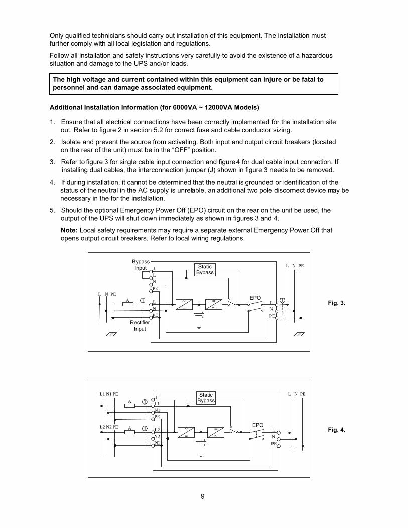
3. Refer to figure 3 for single cable input connection and figure 4 for dual cable input connection. If installing dual cables, the interconnection jumper (J) shown in figure 3 needs to be removed.
4. If during installation, it cannot be determined that the neutral is grounded or identification of the status of the neutral in the AC supply is unreliable, an additional two pole disconnect device may be necessary in the for the installation.
5. Should the optional Emergency Power Off (EPO) circuit on the rear on the unit be used, the output of the UPS will shut down immediately as shown in figures 3 and 4.
Note: Local safety requirements may require a separate external Emergency Power Off that opens output circuit breakers. Refer to local wiring regulations.
~=
=~
StaticBypass
L N PE 1 A
L N PE
1
LNPE
J
LNPE
LNPE
Bypass Input
RectifierInput
~=
=~
StaticBypass
L1 N1 PE 1
1
A
A
L N PE
L2 N2 PE
L1N1PE
J
L2N2PE
LNPE
Fig. 3.
Fig. 4.
9
EPO
EPO
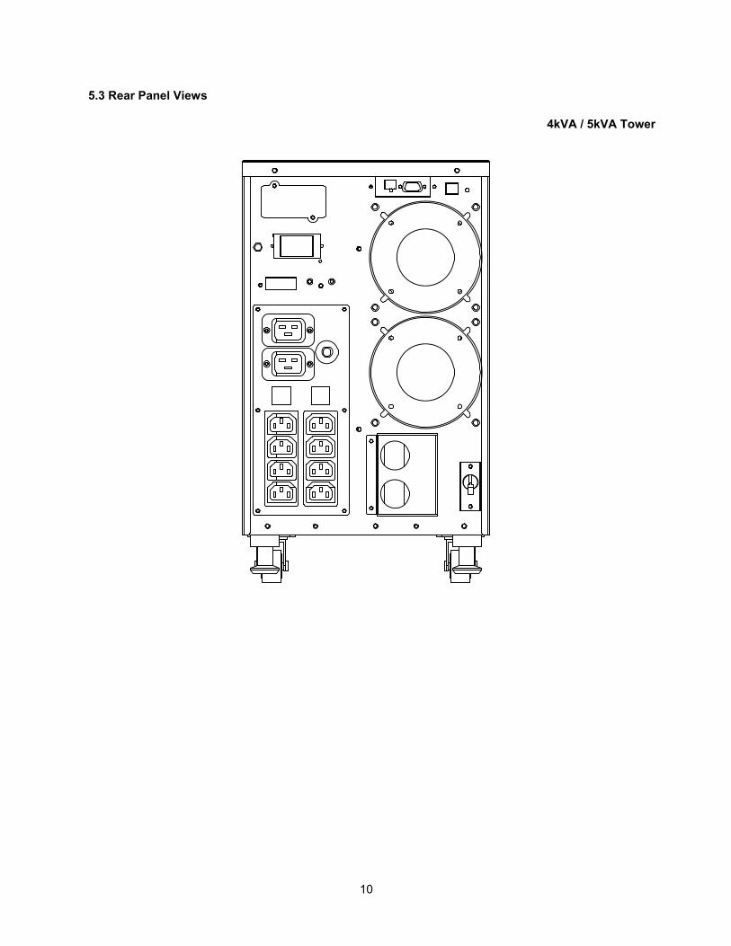
5.3 Rear Panel Views
4kVA / 5kVA Tower
10
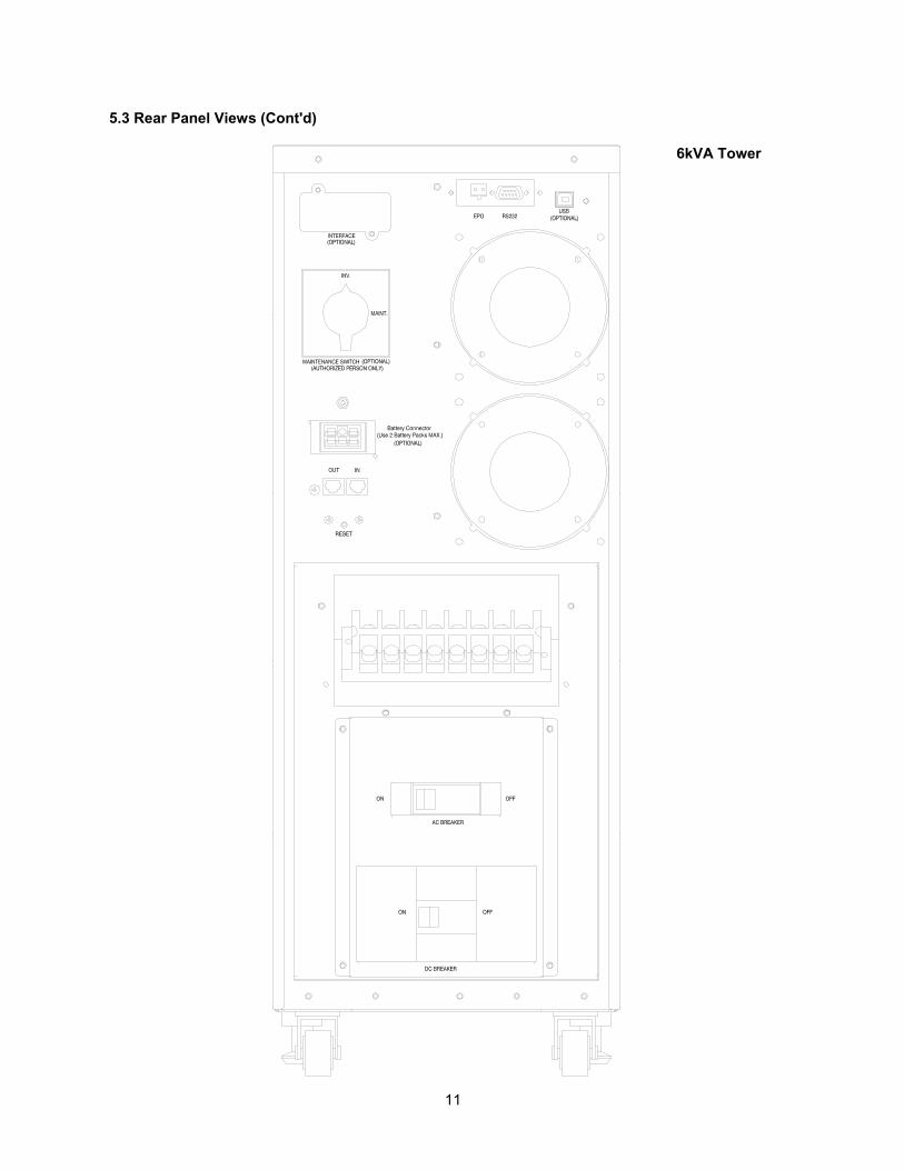
5.3 Rear Panel Views (Cont'd)
6kVA Tower
11
12
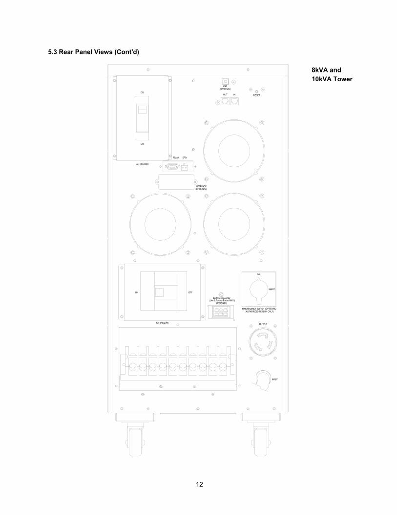
5.3 Rear Panel Views (Cont'd) 8kVA and 10kVA Tower
13
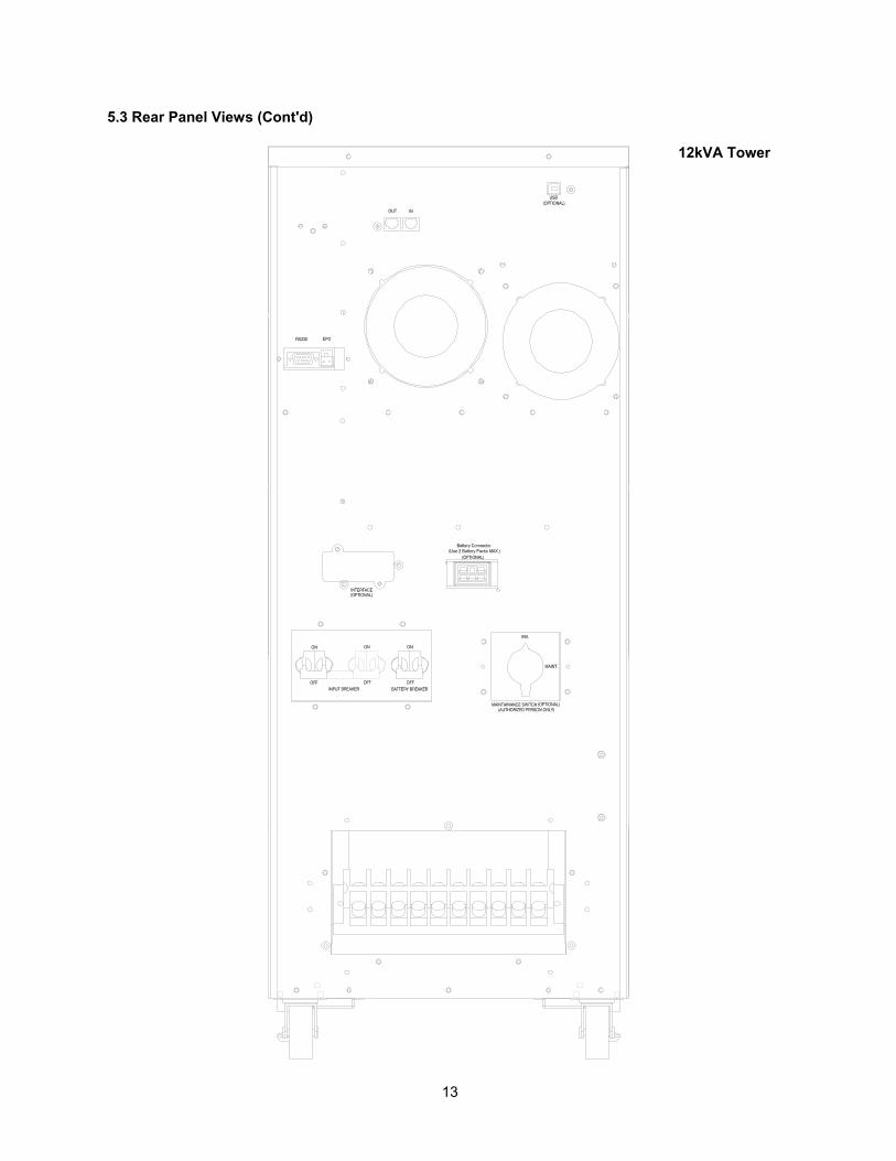
5.3 Rear Panel Views (Cont'd)
12kVA Tower
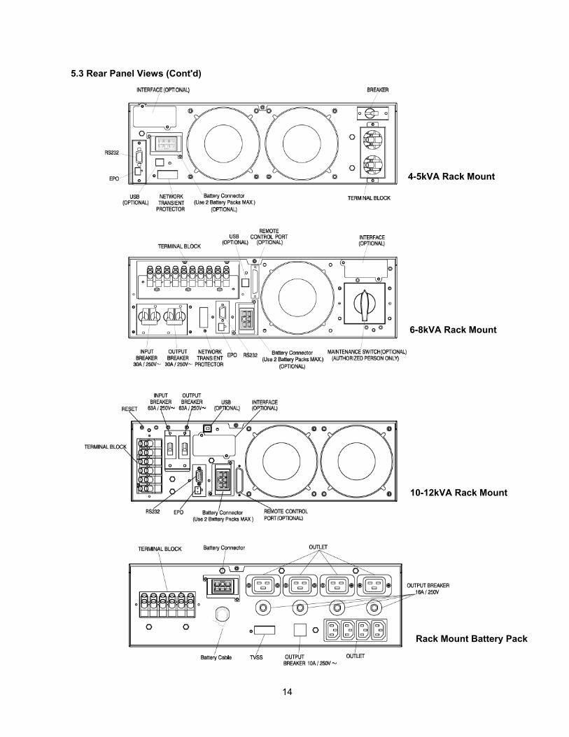
5.3 Rear Panel Views (Cont'd)
14
4-5kVA Rack Mount
6-8kVA Rack Mount
10-12kVA Rack Mount
Rack Mount Battery Pack
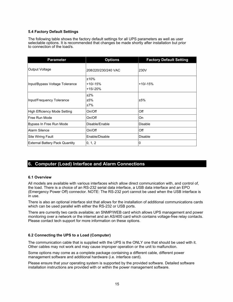
5.4 Factory Default Settings
The following table shows the factory default settings for all UPS parameters as well as user selectable options. It is recommended that changes be made shortly after installation but prior to connection of the load/s.
Parameter Options Factory Default Setting
Output Voltage 208/220/230/240 VAC 230V
Input/Bypass Voltage Tolerance ±10% +10/-15% +15/-20%
+10/-15%
Input/Frequency Tolerance ±2% ±5% ±7%
±5%
High Efficiency Mode Setting On/Off Off
Free Run Mode On/Off On
Bypass In Free Run Mode Disable/Enable Disable
Alarm Silence On/Off Off
Site Wiring Fault Enable/Disable Disable
External Battery Pack Quantity 0, 1, 2 0
6. Computer (Load) Interface and Alarm Connections 6.1 Overview All models are available with various interfaces which allow direct communication with, and control of, the load. There is a choice of an RS-232 serial data interface, a USB data interface and an EPO (Emergency Power Off) connector. NOTE: The RS-232 port cannot be used when the USB interface is in use. There is also an optional interface slot that allows for the installation of additional communications cards which can be used parallel with either the RS-232 or USB ports. There are currently two cards available; an SNMP/WEB card which allows UPS management and power monitoring over a network or the internet and an AS/400 card which contains voltage-free relay contacts. Please contact tech support for more information on these options.
6.2 Connecting the UPS to a Load (Computer)
The communication cable that is supplied with the UPS is the ONLY one that should be used with it.Other cables may not work and may cause improper operation or the unit to malfunction. Some options may come as a complete package containing a different cable, different power management software and additional hardware (i.e. interface card). Please ensure that your operating system is supported by the provided software. Detailed software installation instructions are provided with or within the power management software.
15
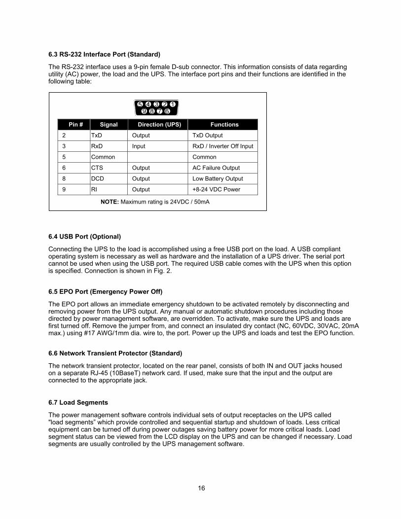
6.3 RS-232 Interface Port (Standard)
The RS-232 interface uses a 9-pin female D-sub connector. This information consists of data regarding utility (AC) power, the load and the UPS. The interface port pins and their functions are identified in the following table:
Pin # Signal Direction (UPS) Functions
2 TxD Output TxD Output
3 RxD Input RxD / Inverter Off Input
5 Common Common
6 CTS Output AC Failure Output
8 DCD Output Low Battery Output
9 RI Output +8-24 VDC Power
6.4 USB Port (Optional)
Connecting the UPS to the load is accomplished using a free USB port on the load. A USB compliant operating system is necessary as well as hardware and the installation of a UPS driver. The serial port cannot be used when using the USB port. The required USB cable comes with the UPS when this optionis specified. Connection is shown in Fig. 2.
6.5 EPO Port (Emergency Power Off)
The EPO port allows an immediate emergency shutdown to be activated remotely by disconnecting andremoving power from the UPS output. Any manual or automatic shutdown procedures including thosedirected by power management software, are overridden. To activate, make sure the UPS and loads arefirst turned off. Remove the jumper from, and connect an insulated dry contact (NC, 60VDC, 30VAC, 20mA
6.6 Network Transient Protector (Standard)
The network transient protector, located on the rear panel, consists of both IN and OUT jacks housed on a separate RJ-45 (10BaseT) network card. If used, make sure that the input and the output are connected to the appropriate jack.
6.7 Load Segments
The power management software controls individual sets of output receptacles on the UPS called "load segments” which provide controlled and sequential startup and shutdown of loads. Less critical equipment can be turned off during power outages saving battery power for more critical loads. Load segment status can be viewed from the LCD display on the UPS and can be changed if necessary. Load segments are usually controlled by the UPS management software.
NOTE: Maximum rating is 24VDC / 50mA
16
max.) using #17 AWG/1mm dia. wire to, the port. Power up the UPS and loads and test the EPO function.
7. Operational Instructions
7.1 Starting Up and Shutting Down the UPS
Start Up
1. Ensure that the unit has been correctly installed and that the input power cable is connected to a properly grounded AC outlet.
2. The unit is turned on by pushing the power push-button on the front panel for more than 3 seconds. 3. The unit sequences through its functional check, AC line synchronization and inverter startup. Power
is then applied to the outlets. 4. During this sequence, the LCD panel displays “Ready On”. An LED illuminates when output power is
available and the LCD panel displays “Line mode”. 5. The loads can now be turned on.
Shut Down
1. Shut down and turn off all connected loads. 2. Push the power push-button on the front panel for five seconds or more. An audible alarm will sound
and the unit will shut down. 3. The LCD panel displays “UPS OFF” for a few seconds. 4. In emergency situations or applications which require such, the EPO located on the back of the unit
should be used.
7.2 Push-button Operations
There are five operational push-buttons on the front panel:
1. ON/OFF - This push-button turns the unit on and off. To initiate a start-up or shut-down, press and hold this push-button for 3 seconds.
2. STATUS - This push-button is used to check current UPS and load settings, information and power measurements. To activate, press it for at least 2 seconds. There are 15 different functions that can be checked in this mode and pressing this push-button once each time scrolls through each function. If the push-button is not pressed within 10 seconds, the display reverts to its original mode.
3. FUNC - This push-button selects or enables various user-selectable parameters. There are 14 different parameters which can be scrolled through. To activate, press it for at least 2 secs. After locating a setting or particular parameter, press the Enter push-button to select that parameter and view its current setting. Press the Function push-button once again to scroll through the setting options. Once the desired setting is located, press the Enter push-button to enable the new setting and once again to save it (you will be prompted to do so). If no action is taken within 10 seconds, the display reverts to its previous mode.
4. ENTER - This push-button is used to enter, enable and/or confirm a selected function.
5. ESCAPE - This push-button is used to exit a menu and return to the main display.
17
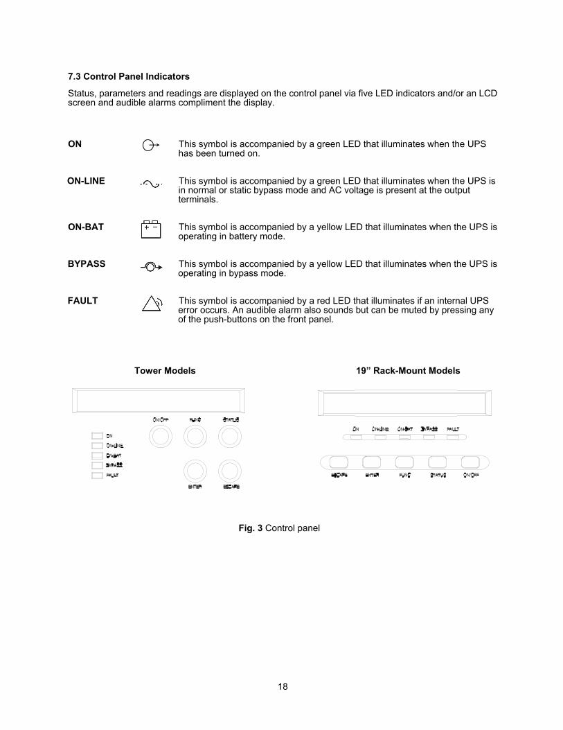
7.3 Control Panel Indicators
Status, parameters and readings are displayed on the control panel via five LED indicators and/or an LCD screen and audible alarms compliment the display. ON This symbol is accompanied by a green LED that illuminates when the UPS
has been turned on. ON-LINE This symbol is accompanied by a green LED that illuminates when the UPS is
in normal or static bypass mode and AC voltage is present at the output terminals.
ON-BAT This symbol is accompanied by a yellow LED that illuminates when the UPS is
operating in battery mode.
BYPASS This symbol is accompanied by a yellow LED that illuminates when the UPS is operating in bypass mode.
FAULT This symbol is accompanied by a red LED that illuminates if an internal UPS
error occurs. An audible alarm also sounds but can be muted by pressing any of the push-buttons on the front panel.
Tower Models 19” Rack-Mount Models
Fig. 3 Control panel
18
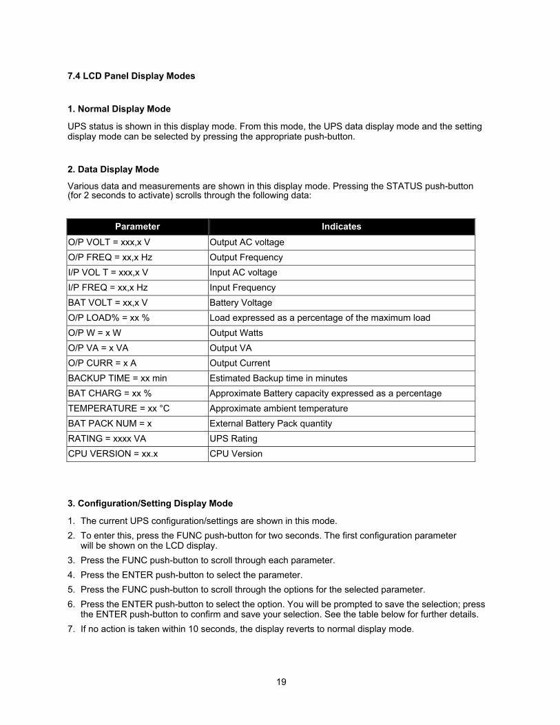
7.4 LCD Panel Display Modes
1. Normal Display Mode
UPS status is shown in this display mode. From this mode, the UPS data display mode and the setting display mode can be selected by pressing the appropriate push-button.
2. Data Display Mode
Various data and measurements are shown in this display mode. Pressing the STATUS push-button(for 2 seconds to activate) scrolls through the following data:
Parameter Indicates O/P VOLT = xxx,x V Output AC voltage O/P FREQ = xx,x Hz Output Frequency I/P VOL T = xxx,x V Input AC voltage I/P FREQ = xx,x Hz Input Frequency BAT VOLT = xx,x V Battery Voltage O/P LOAD% = xx % Load expressed as a percentage of the maximum load O/P W = x W Output Watts O/P VA = x VA Output VA O/P CURR = x A Output Current BACKUP TIME = xx min Estimated Backup time in minutes BAT CHARG = xx % Approximate Battery capacity expressed as a percentage TEMPERATURE = xx °C Approximate ambient temperature BAT PACK NUM = x External Battery Pack quantity RATING = xxxx VA UPS Rating CPU VERSION = xx.x CPU Version
3. Configuration/Setting Display Mode
1. The current UPS configuration/settings are shown in this mode. 2. To enter this, press the FUNC push-button for two seconds. The first configuration parameter
will be shown on the LCD display. 3. Press the FUNC push-button to scroll through each parameter. 4. Press the ENTER push-button to select the parameter. 5. Press the FUNC push-button to scroll through the options for the selected parameter. 6. Press the ENTER push-button to select the option. You will be prompted to save the selection; press
the ENTER push-button to confirm and save your selection. See the table below for further details. 7. If no action is taken within 10 seconds, the display reverts to normal display mode.
19
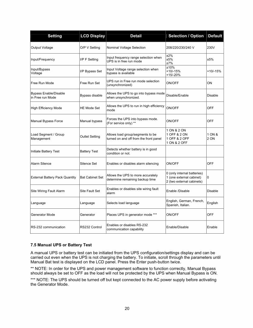
Setting LCD Display Detail Selection / Option Default
208/220/230/240 V 230V Output Voltage O/P V Setting Nominal Voltage Selection
Input/Frequency I/P F Setting Input frequency range selection when UPS is in free run mode
±2% ±5% ±7%
±5%
Input/Bypass Voltage I/P Bypass Set Input Voltage range selection when
bypass is available
±10% +10/-15% +15/-20%
+10/-15%
Free Run Mode Free Run Set UPS run in Free run mode selection (unsynchronized) ON/OFF ON
Bypass Enable/Disable in Free run Mode Bypass disable Allows the UPS to go into bypass mode
when unsynchronized. Disable/Enable Disable
High Efficiency Mode HE Mode Set Allows the UPS to run in high efficiency mode ON/OFF OFF
Manual Bypass Force Manual bypass Forces the UPS into bypass mode. (For service only) ** ON/OFF OFF
Load Segment / Group Management Outlet Setting Allows load group/segments to be
turned on and off from the front panel
1 ON & 2 ON 1 OFF & 2 ON 1 OFF & 2 OFF 1 ON & 2 OFF
1 ON & 2 ON
Initiate Battery Test Battery Test Detects whether battery is in good condition or not.
Alarm Silence Silence Set Enables or disables alarm silencing ON/OFF OFF
External Battery Pack Quantity Bat Cabinet Set Allows the UPS to more accurately determine remaining backup time
0 (only internal batteries) 1 (one external cabinet) 2 (two external cabinets)
0
Site Wiring Fault Alarm Site Fault Set Enables or disables site wiring fault alarm Enable /Disable Disable
Language Language Selects load language English, German, French, Spanish, Italian. English
Generator Mode Generator Places UPS in generator mode *** ON/OFF OFF
RS-232 communication RS232 Control Enables or disables RS-232 communication capability Enable/Disable Enable
7.5 Manual UPS or Battery Test
A manual UPS or battery test can be initiated from the UPS configuration/settings display and can be carried out even when the UPS is not charging the battery. To initiate, scroll through the parameters until Manual Bat test is displayed on the LCD panel. Press the Enter push-button twice. ** NOTE: In order for the UPS and power management software to function correctly, Manual Bypass should always be set to OFF as the load will not be protected by the UPS when Manual Bypass is ON. *** NOTE: The UPS should be turned off but kept connected to the AC power supply before activating the Generator Mode.
20
7.6 Audible Alarms
1. If the UPS is on battery and the “ON BATTERY” LED is illuminated, the unit will beep every 5 seconds.
2. If the battery capacity is low and the “ON BATTERY” LED is flashing, the unit will beep twice every 5 seconds.
3. If the UPS is in bypass mode and the “BYPASS” LED is illuminated, the unit will not beep. 4. If the UPS has an internal fault and the “ALARM” LED is illuminated, the unit will emit a constant
alarm tone and display the cause of the fault on the LCD panel. 5. To silence an alarm, press any of the three push-buttons on the front panel. The alarm will be
silenced under all conditions except when the battery is low, under which condition the alarm cannot be silenced.
6. The audible alarm function can be de-activated internally by selecting the appropriate parameter from the LCD panel.
21
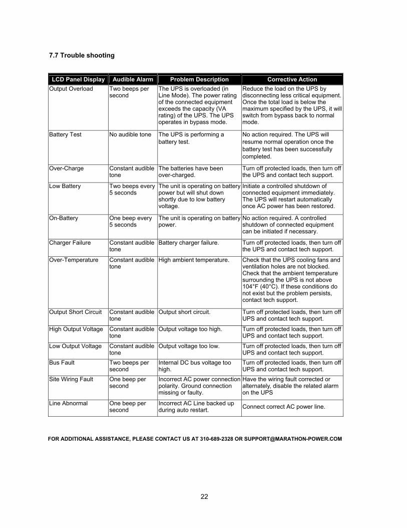
7.7 Trouble shooting
LCD Panel Display Audible Alarm Problem Description Corrective Action Output Overload Two beeps per
second The UPS is overloaded (in Line Mode). The power rating of the connected equipment exceeds the capacity (VA rating) of the UPS. The UPS operates in bypass mode.
Reduce the load on the UPS by disconnecting less critical equipment. Once the total load is below the maximum specified by the UPS, it will switch from bypass back to normal mode.
Battery Test No audible tone The UPS is performing a battery test.
No action required. The UPS will resume normal operation once the battery test has been successfully completed.
Over-Charge Constant audible tone
The batteries have been over-charged.
Turn off protected loads, then turn off the UPS and contact tech support.
Low Battery Two beeps every 5 seconds
The unit is operating on battery power but will shut down shortly due to low battery voltage.
Initiate a controlled shutdown of connected equipment immediately. The UPS will restart automatically once AC power has been restored.
On-Battery One beep every 5 seconds
The unit is operating on battery power.
No action required. A controlled shutdown of connected equipment can be initiated if necessary.
Charger Failure Constant audible tone
Battery charger failure. Turn off protected loads, then turn off the UPS and contact tech support.
Over-Temperature Constant audible tone
High ambient temperature. Check that the UPS cooling fans and ventilation holes are not blocked. Check that the ambient temperature surrounding the UPS is not above 104°F (40°C). If these conditions do not exist but the problem persists, contact tech support.
Output Short Circuit Constant audible tone
Output short circuit. Turn off protected loads, then turn off UPS and contact tech support.
High Output Voltage Constant audible tone
Output voltage too high. Turn off protected loads, then turn off UPS and contact tech support.
Low Output Voltage Constant audible tone
Output voltage too low. Turn off protected loads, then turn off UPS and contact tech support.
Bus Fault Two beeps per second
Internal DC bus voltage too high.
Turn off protected loads, then turn off UPS and contact tech support.
Site Wiring Fault One beep per second
Incorrect AC power connectionpolarity. Ground connection missing or faulty.
Have the wiring fault corrected or alternately, disable the related alarm on the UPS
Line Abnormal One beep per second
Incorrect AC Line backed up during auto restart. Connect correct AC power line.
22
FOR ADDITIONAL ASSISTANCE, PLEASE CONTACT US AT 310-689-2328 OR [email protected]
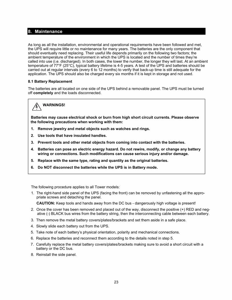
8. Maintenance As long as all the installation, environmental and operational requirements have been followed and met, the UPS will require little or no maintenance for many years. The batteries are the only component that should eventually need replacing. Their useful life depends primarily on the following two factors; the ambient temperature of the environment in which the UPS is located and the number of times they’re called into use (i.e. discharged). In both cases, the lower the number, the longer they will last. At an ambienttemperature of 77°F (25°C), typical battery lifetime is 4-5 years. A test of the UPS and batteries should be carried out at regular intervals (every 6 to 12 months) to verify that back-up time is still adequate for the application. The UPS should also be charged every six months if it is kept in storage and not used.
8.1 Battery Replacement
The batteries are all located on one side of the UPS behind a removable panel. The UPS must be turned off completely and the loads disconnected.
WARNINGS!
Batteries may cause electrical shock or burn from high short circuit currents. Please observe the following precautions when working with them:
1. Remove jewelry and metal objects such as watches and rings.
2. Use tools that have insulated handles.
3. Prevent tools and other metal objects from coming into contact with the batteries.
4. Batteries can pose an electric energy hazard. Do not rewire, modify, or change any battery wiring or connections. Such modifications can cause serious injury and/or damage.
5. Replace with the same type, rating and quantity as the original batteries.
6. Do NOT disconnect the batteries while the UPS is in Battery mode.
The following procedure applies to all Tower models: 1. The right-hand side panel of the UPS (facing the front) can be removed by unfastening all the appro-
priate screws and detaching the panel. CAUTION: Keep tools and hands away from the DC bus - dangerously high voltage is present!
2. Once the cover has been removed and placed out of the way, disconnect the positive (+) RED and neg- ative (-) BLACK bus wires from the battery string, then the interconnecting cable between each battery. 3. Then remove the metal battery covers/plates/brackets and set them aside in a safe place.
4. Slowly slide each battery out from the UPS. 5. Take note of each battery’s physical orientation, polarity and mechanical connections. 6. Replace the batteries and reconnect them according to the details noted in step 5. 7. Carefully replace the metal battery covers/plates/brackets making sure to avoid a short circuit with a
battery or the DC bus. 8. Reinstall the side panel.
23
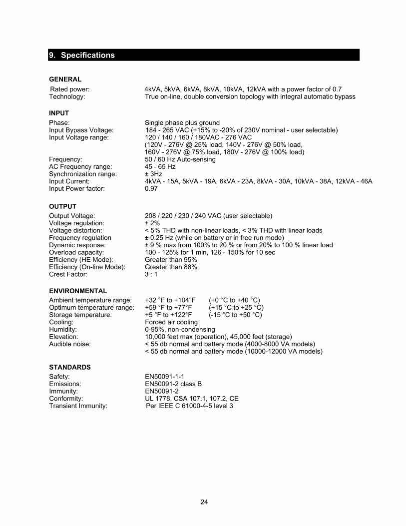
9. Specifications GENERAL
Rated power: 4kVA, 5kVA, 6kVA, 8kVA, 10kVA, 12kVA with a power factor of 0.7 Technology: True on-line, double conversion topology with integral automatic bypass INPUT
Phase: Single phase plus groundInput Bypass Voltage: 184 - 265 VAC (+15% to -20% of 230V nominal - user selectable) Input Voltage range: 120 / 140 / 160 / 180VAC - 276 VAC (120V - 276V @ 25% load, 140V - 276V @ 50% load, 160V - 276V @ 75% load, 180V - 276V @ 100% load) Frequency: 50 / 60 Hz Auto-sensing AC Frequency range: 45 - 65 Hz Synchronization range: ± 3Hz Input Current: 4kVA - 15A, 5kVA - 19A, 6kVA - 23A, 8kVA - 30A, 10kVA - 38A, 12kVA - 46A Input Power factor: 0.97 OUTPUT Output Voltage: 208 / 220 / 230 / 240 VAC (user selectable) Voltage regulation: ± 2% Voltage distortion: < 5% THD with non-linear loads, < 3% THD with linear loads Frequency regulation ± 0.25 Hz (while on battery or in free run mode) Dynamic response: ± 9 % max from 100% to 20 % or from 20% to 100 % linear load Overload capacity: 100 - 125% for 1 min, 126 - 150% for 10 sec Efficiency (HE Mode): Greater than 95% Efficiency (On-line Mode): Greater than 88% Crest Factor: 3 : 1
ENVIRONMENTAL Ambient temperature range: +32 °F to +104°F (+0 °C to +40 °C) Optimum temperature range: +59 °F to +77°F (+15 °C to +25 °C) Storage temperature: +5 °F to +122°F (-15 °C to +50 °C) Cooling: Forced air cooling Humidity: 0-95%, non-condensing Elevation: 10,000 feet max (operation), 45,000 feet (storage) Audible noise: < 55 db normal and battery mode (4000-8000 VA models) < 55 db normal and battery mode (10000-12000 VA models)
STANDARDS Safety: EN50091-1-1 Emissions: EN50091-2 class B Immunity: EN50091-2 Conformity: UL 1778, CSA 107.1, 107.2, CE Transient Immunity: Per IEEE C 61000-4-5 level 3
24
25
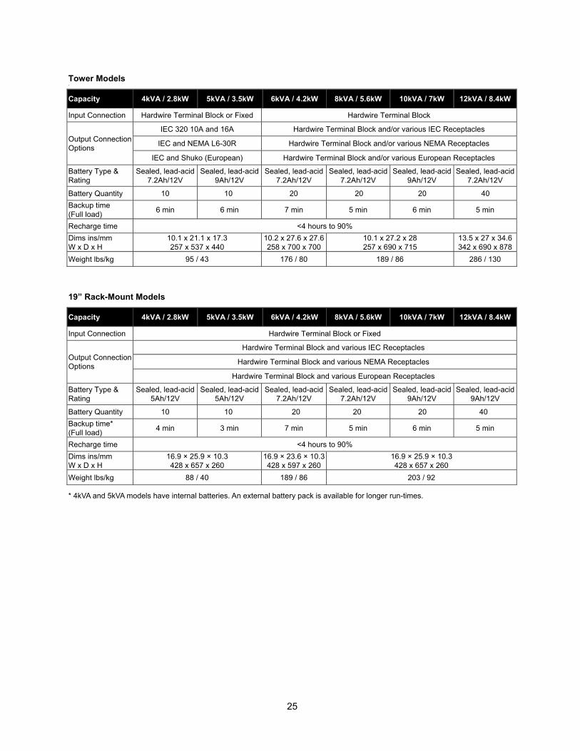
Tower Models
Capacity 4kVA / 2.8kW 5kVA / 3.5kW 6kVA / 4.2kW 8kVA / 5.6kW 10kVA / 7kW 12kVA / 8.4kW
Input Connection Hardwire Terminal Block or Fixed Hardwire Terminal Block
Output Connection Options
IEC 320 10A and 16A Hardwire Terminal Block and/or various IEC Receptacles
IEC and NEMA L6-30R Hardwire Terminal Block and/or various NEMA Receptacles
IEC and Shuko (European) Hardwire Terminal Block and/or various European Receptacles
Battery Type & Rating
Sealed, lead-acid 7.2Ah/12V
Sealed, lead-acid 9Ah/12V
Sealed, lead-acid 7.2Ah/12V
Sealed, lead-acid 7.2Ah/12V
Sealed, lead-acid 9Ah/12V
Sealed, lead-acid 7.2Ah/12V
Battery Quantity 10 10 20 20 20 40 Backup time (Full load) 6 min 6 min 7 min 5 min 6 min 5 min
Recharge time <4 hours to 90% Dims ins/mm W x D x H
10.1 x 21.1 x 17.3 257 x 537 x 440
10.2 x 27.6 x 27.6258 x 700 x 700
10.1 x 27.2 x 28 257 x 690 x 715
13.5 x 27 x 34.6 342 x 690 x 878
Weight lbs/kg 95 / 43 176 / 80 189 / 86 286 / 130
19” Rack-Mount Models
Capacity 4kVA / 2.8kW 5kVA / 3.5kW 6kVA / 4.2kW 8kVA / 5.6kW 10kVA / 7kW 12kVA / 8.4kW
Input Connection Hardwire Terminal Block or Fixed
Output Connection Options
Hardwire Terminal Block and various IEC Receptacles
Hardwire Terminal Block and various NEMA Receptacles
Hardwire Terminal Block and various European Receptacles
Battery Type & Rating
Sealed, lead-acid 5Ah/12V
Sealed, lead-acid 5Ah/12V
Sealed, lead-acid 7.2Ah/12V
Sealed, lead-acid 7.2Ah/12V
Sealed, lead-acid 9Ah/12V
Sealed, lead-acid 9Ah/12V
Battery Quantity 10 10 20 20 20 40 Backup time* (Full load) 4 min 3 min 7 min 5 min 6 min 5 min
Recharge time <4 hours to 90% Dims ins/mm W x D x H
16.9 × 25.9 × 10.3 428 x 657 x 260
16.9 × 23.6 × 10.3428 x 597 x 260
16.9 × 25.9 × 10.3 428 x 657 x 260
Weight lbs/kg 88 / 40 189 / 86 203 / 92
* 4kVA and 5kVA models have internal batteries. An external battery pack is available for longer run-times.
26
10. Warranty
10.1 Limited Three-Year Warranty and ExclusionsNOTE: For this warranty to be valid, completed registration information must be received within 30 days of original purchase.Marathon Power warrants to the original purchaser, who must have properly registered the product within 30 days of purchase, and not for the benefit of anyone else that this product at the time of its sale by Marathon Power is free of defects in materials and workmanship for three (3) years (batteries for 2 years within the USA, Canada and Mexico, otherwise 1 year) from the original purchase date. Marathon Power will correct such defects by repair or replacement, at its option, if within such three year period the product is returned prepaid and all warranty claim instructions are followed. This warranty excludes labor for removal or reinstallation of this product. This warranty is void if this product is installed improperly or in an improper environment, overloaded, misused, opened, abused, or altered in any manner, or is not used under normal operating conditions or not in accordance with all labels or instructions. There are no other or implied warranties of any kind, including merchantability and fitness for a particular purpose, but if any implied warranty is required by the applicable jurisdiction, the duration of any such implied warranty, including merchantability and fitness for a particular purpose, is limited to three years. Marathon Power is not liable for incidental, indirect, special or consequential damages, including damage to, or loss of use of, any equipment, lost sales or profits or delay or failure to perform this warranty obligation.
10.2 Limitations & Claims This warranty does not cover any Marathon Power UPS or any properly connected electronic equipment which has been improperly installed, overloaded, abused or altered in any manner, or is not used under normal operating conditions, or in accordance with any labels or instructions, and does not cover any damage to properly connected electronic equipment resulting from a cause other than a “surge”.Damage caused by failure to provide a suitable installation environment for the product (including, but not limited to, lack of a good ground) will not be covered by this warranty. This warranty does not apply to damage caused by direct lightning strikes, or damage caused by electrical disturbances that exceed published product specifications. These products are intended to limit the maximum amplitude of transient voltage surges on power lines to specified values. They are not intended to function as surge arrestors. The UPS is intended to be installed on the load side of the service entrance and has been tested to verify that transient voltage surges are limited when subject to non-repetitive transient voltage surge events. This warranty excludes any incidental, indirect, special or consequential damages, including without limitation, labor for removal or reinstallation of the Marathon Power UPS or any connected electronic equipment, data loss or alteration loss of equipment use, lost sales or profits and any such damages for delay or failure to perform this warranty obligation. This warranty is in lieu of and excludes all implied warranties of merchantability or fitness for use. In addition, the warranty does not cover restoration of lost data and reinstallation of software. Some states may not allow the exclusion or limitation of incidental or consequential damages or other remedies, so the above exclusions or limitations may not apply to you.Take the following stps to file a warranty claim: Contact us at Marathon Power, Inc., Attn: Returns, 2538 E. 54th Street, Huntington Park, California 90255 or call (310) 689-2328 within 30 days of the occurrence. Be prepared to provide detailed information about the event, any damage, the UPS model number, purchase date and location. You will then be provided with a Return Authorization Number (RAN), and be instructed to forward your proof of purchase (receipt), an explanation of the event and your UPS. If Marathon Power determines that the damage was due to a “surge”, we may request that all connected equipment be submitted for evaluation. Marathon Power is not responible for shipping costs. In the event that the equipment has been damaged by a “surge” Marathon Power will reimburse you for repair or replacement at fair market value (on a pro rata basis) as indicated by the respective amounts above. The warranty coverage is above and beyond, only to the extent needed, of that provided by any other source, including but not limited to any connected equipment coverage, any manufacturer’s warranty or insurance policy. To receive payment for repair to damage due to a “surge,” the original purchaser should (upon prior approval from Marathon Power) have such equipment repaired by an authorized service center of such equipment’s manufacturer. The original purchaser will submit a repair bill along with a statement from the repair facility documenting the nature of the damage and how it was sustained to said equipment.

Notes
______________________________________________________________________________
___________________________________________________________________________________
______________________________________________________________________________
___________________________________________________________________________________
____________________________________________________________________________________
27


vault4-12kuserman2010
Copyright Marathon Power, Inc. 2010www.marathon-power.com