Embed Size (px)
Citation preview

VBT-75PVACUUM BOTTLE TESTER
USER’S MANUAL
Vanguard Instruments Company, Inc.1520 S. Hellman Ave. Ontario, California 91761, USA
TEL: (909) 923-9390 FAX: (909) 923-9391
March 2015Revision 1
VBT-75P USER’S MANUAL REV 1
i
SAFETY SUMMARY
FOLLOW EXACT OPERATING PROCEDURES Any deviation from the procedures described in this operator’s manual may create one or more safety hazards, damage the VBT-75P, or cause errors in the test results; Vanguard Instruments Co., Inc. assumes no liability for unsafe or improper use of the VBT-75P. The following safety precautions must be observed during all phases of test set up, test hookups, testing, and test-lead disconnects.
SAFETY WARNINGS AND CAUTIONS This device shall be used only by trained operators. All circuit breakers under test shall be off line and fully isolated.
SERVICE AND REPAIR • Do not install substitute parts or perform any unauthorized modification to any VBT-75P test unit. • Repairs must be performed only by Vanguard Instruments Company factory personnel or by an authorized
repair service provider. Unauthorized modifications can cause safety hazards and will void the manufacturer’s warranty.
EQUIPMENT RATINGS IP Rating: The enclosure for the VBT-75P has an IP rating of 32.
Pollution Degree: The VBT-75P has a pollution rating of 2.
Operating Voltage: The VBT-75P is rated for use with an operating voltage of 120V or 240V, auto-ranging ±10% of selected voltage.
Power Cord: The VBT-75P is supplied with a 16 AWG, 16A power cord with a NEMA 5-15P plug. Replacement cable shall have the same or better rating and is available through the manufacturer.
VENTILATION REQUIREMENTS The VBT-75P must be operated with the enclosure lid open.
SAFETY SYMBOLS
Indicates that caution should be exercised
OR
Indicates location of chassis ground terminal
CLEANING To clean the VBT-75P:
• Disconnect all cables and turn the unit off. • Use a soft, lint-free cloth to wipe all surfaces clean. • Avoid getting moisture in openings and connectors. • Don't use any cleaning products or compressed air.

REV 1 VBT-75P USER’S MANUAL
ii
TABLE OF CONTENTS CONVENTIONS USED IN THIS DOCUMENT ....................................................................... 1 1.0 INTRODUCTION .................................................................................................................... 2
1.1 General Description and Features ................................................................................... 2 1.2 Printer Paper .................................................................................................................... 3 1.3 Technical Specifications ................................................................................................... 4 1.4 VBT-75P Controls and Indicators ..................................................................................... 5
2.0 CABLE CONNECTIONS .......................................................................................................... 7 3.0 OPERATING PROCEDURES ................................................................................................... 8
3.1 Setting the Date and Time ............................................................................................... 8 3.2 Adjusting LCD Screen Contrast ........................................................................................ 8 3.3 Entering Test Record Header Information ....................................................................... 9 3.4 Performing a Test ........................................................................................................... 11 3.5 Printing a Directory of Test Records Stored in the VBT-75P's Memory ........................ 15 3.6 Reviewing a Test Record ................................................................................................ 17 3.7 Restoring a Test Record ................................................................................................. 19 3.8 Deleting Test Records .................................................................................................... 21
LIST OF TABLES Table 1. VBT-75P Technical Specifications ...................................................................................... 4 Table 2. Functional Descriptions of VBT-75P Controls and Indicators ........................................... 6
LIST OF FIGURES Figure 1. VBT-75P Controls and Indicators ..................................................................................... 5 Figure 2. VBT-75P Connection Diagram .......................................................................................... 7 Figure 3. Sample Test Results Printout ......................................................................................... 14 Figure 4. Sample Test Record Directory Printout ......................................................................... 16
REV 1 VBT-75P USER’S MANUAL
1
CONVENTIONS USED IN THIS DOCUMENT
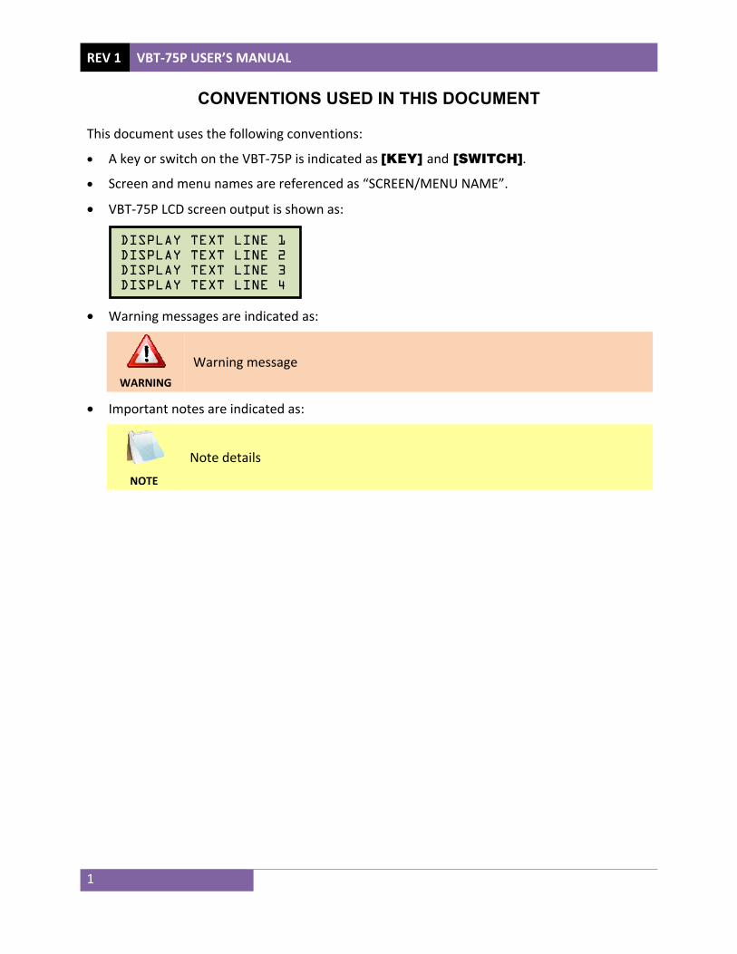
This document uses the following conventions:
• A key or switch on the VBT-75P is indicated as [KEY] and [SWITCH].
• Screen and menu names are referenced as “SCREEN/MENU NAME”.
• VBT-75P LCD screen output is shown as:
• Warning messages are indicated as:
WARNING
Warning message
• Important notes are indicated as:
NOTE
Note details
DISPLAY TEXT LINE 1 DISPLAY TEXT LINE 2 DISPLAY TEXT LINE 3 DISPLAY TEXT LINE 4

VBT-75P USER’S MANUAL REV 1
2
1.0 INTRODUCTION 1.1 General Description and Features The VBT-75P is a microprocessor-based, portable 75 kV dc vacuum bottle tester. This lightweight, portable tester is designed for testing circuit-breaker vacuum bottles in the field and at the shop.
Test voltages can be selected from 10 kV dc to 75 Kv dc in 1 Kv steps. The high voltage test time can be set from 5 seconds to 2 minutes. The test voltage is raised to the selected voltage and held for the test time duration. After the test time duration has elapsed and the leakage current did not pass the pre-set value of 100 µA, 200 µA, or 300 µA, the test voltage is returned to zero and a "Pass" message is displayed. If a flash-over condition occurs, such as bottle failure, the test voltage is immediately turned off, a “Failure” message is displayed on the LCD screen, and the “TEST FAIL” LED light on the unit is also illuminated.
The presence of high voltage is indicated by an audible tone and an illuminated “HIGH VOLTAGE” LED light. For additional operator safety, an “ARM” switch must be held down during testing.
The VBT-75P features a back-lit LCD screen (20 characters by 4 lines) that is viewable in both bright sunlight and low-light levels. A rugged, 16-key, membrane keypad is used to control the unit. Test results can be printed on the built-in 2.5" wide thermal printer.
The VBT-75P can store up to 84 records of 16 readings in Flash EEPROM. Test records can be retrieved and printed on the built-in thermal printer, or they can be transferred to a PC via the unit’s RS-232C interface. Windows®-based software is provided with each unit. Using this software, test records can be retrieved from the VBT-75P and then stored on the PC for future analysis and report generation. Additionally, test records can be exported in PDF, Excel, and XML formats.
The VBT-75P is furnished with a 10-foot test cable that is terminated with a quick-disconnect test clip. A transportation case is also included.

REV 1 VBT-75P USER’S MANUAL
3
1.2 Printer Paper The VBT-75P's built-in thermal printer uses 2.5-inch wide thermal paper for printing test results. To maintain the highest print quality and to avoid paper jams, the use of thermal paper supplied by Vanguard Instruments Company is highly recommended. Additional paper can be ordered from the following sources:
Vanguard Instruments Co, Inc. 1520 S. Hellman Avenue Ontario, CA 91761 Tel: 909-923-9390 Fax: 909-923-9391 Part Number: VIC TP-3 paper BG Instrument Co. 13607 E. Trent Avenue Spokane, WA 99216 Tel: 509-893-9881 Fax: 509-893-9803 Part Number: VIC TP-3 paper

VBT-75P USER’S MANUAL REV 1
4
1.3 Technical Specifications Table 1. VBT-75P Technical Specifications
TYPE Portable 75 kV vacuum bottle tester PHYSICAL SPECIFICATIONS Dimensions: 17”W x 10.5”H x 6.5” D (42.7 cm x 26.9 cm x 16.5 cm)
Weight: 12 lbs. (5.44 Kg) INPUT POWER 2 amps, 90-240 Vac, 50/60 Hz
OUTPUT VOLTAGE 10 kV to 75 kV dc in 1 kV steps; accuracy: 1.5% OUTPUT RIPPLE VOLTAGE 3% max
DISCHARGE TIME Maximum discharge time for internal high voltage is 3 seconds DISPLAY back-lit LCD (20 characters x 4 lines); viewable in bright sunlight and low-light
levels KEYPAD rugged membrane keypad (10 alpha-numeric keys, 6 function keys)
COMPUTER INTERFACE one RS-232C port INTERNAL DATA STORAGE stores up to 84 records of 16 readings each
PC SOFTWARE Windows-based software is included with purchase price PRINTER Built-in 2.5" wide thermal printer
ENVIRONMENT Operating: -10˚ to 50˚ C (15˚ to +122˚ F); Storage: -30˚ C to 70˚ C (-22˚ to +158˚ F)
HUMIDITY (MAX) 90% RH @ 40˚ C (104˚ F) non-condensing ALTITUDE (MAX) 2000m (6562 ft) to fully safety specifications
CABLES one 10-foot high-voltage cable, one 10-foot high voltage return cable, one ground cable, one power cord
FURNISHED ACCESSORIES Shipping case is included WARRANTY One year on parts and labor
NOTE
The above specifications are valid at nominal operating voltage and at a temperature of 25°C (77°F). Specifications may change without prior notice.
REV 1 VBT-75P USER’S MANUAL
5
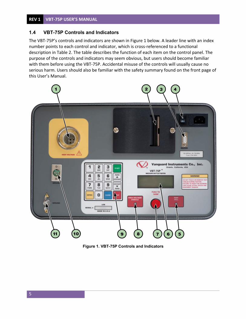
1.4 VBT-75P Controls and Indicators The VBT-75P’s controls and indicators are shown in Figure 1 below. A leader line with an index number points to each control and indicator, which is cross-referenced to a functional description in Table 2. The table describes the function of each item on the control panel. The purpose of the controls and indicators may seem obvious, but users should become familiar with them before using the VBT-75P. Accidental misuse of the controls will usually cause no serious harm. Users should also be familiar with the safety summary found on the front page of this User’s Manual.
Figure 1. VBT-75P Controls and Indicators
VBT-75P USER’S MANUAL REV 1
6
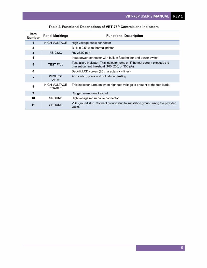
Table 2. Functional Descriptions of VBT-75P Controls and Indicators
Item Number Panel Markings Functional Description
1 HIGH VOLTAGE High voltage cable connector 2 Built-in 2.5" wide thermal printer 3 RS-232C RS-232C port 4 Input power connector with built-in fuse holder and power switch
5 TEST FAIL Test failure indicator. This indicator turns on if the test current exceeds the present current threshold (100, 200, or 300 μA).
6 Back-lit LCD screen (20 characters x 4 lines)
7 PUSH TO "ARM"
Arm switch; press and hold during testing.
8 HIGH VOLTAGE ENABLE
This indicator turns on when high test voltage is present at the test leads.
9 Rugged membrane keypad 10 GROUND High voltage return cable connector
11 GROUND VBT ground stud. Connect ground stud to substation ground using the provided cable.
REV 1 VBT-75P USER’S MANUAL
7
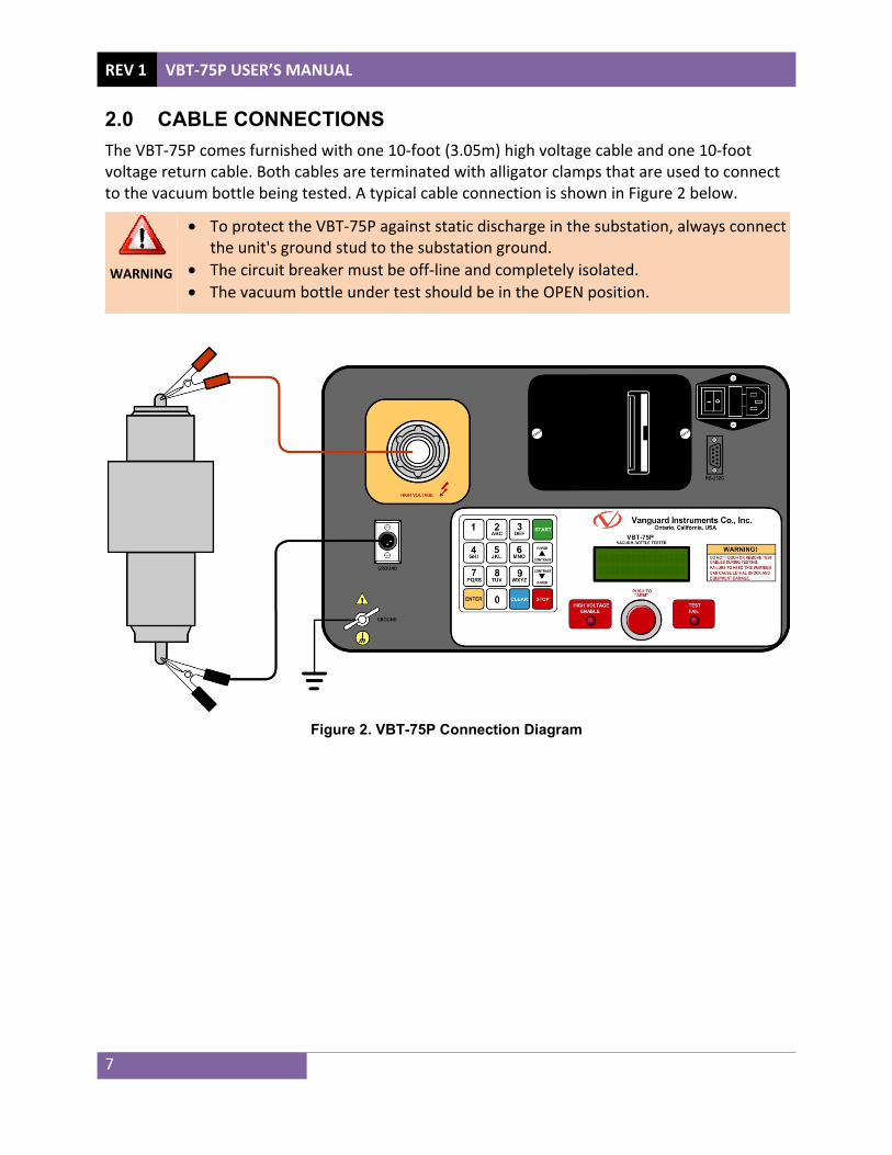
2.0 CABLE CONNECTIONS The VBT-75P comes furnished with one 10-foot (3.05m) high voltage cable and one 10-foot voltage return cable. Both cables are terminated with alligator clamps that are used to connect to the vacuum bottle being tested. A typical cable connection is shown in Figure 2 below.
WARNING
• To protect the VBT-75P against static discharge in the substation, always connect the unit's ground stud to the substation ground.
• The circuit breaker must be off-line and completely isolated. • The vacuum bottle under test should be in the OPEN position.
Figure 2. VBT-75P Connection Diagram

VBT-75P USER’S MANUAL REV 1
8
3.0 OPERATING PROCEDURES 3.1 Setting the Date and Time Follow the steps below to set the date and time for the VBT-75P's internal clock:
a. Start from the "START-UP" menu:
Press the [2] key (SETUP).
b. The following screen will be displayed:
Press the [4] key (NEXT PAGE).
c. The following screen will be displayed:
Press the [2] key (SET TIME).
d. The following screen will be displayed:
Enter the date and time using the membrane keypad. The date and time will be set and you will be returned to the "START-UP" menu.
3.2 Adjusting LCD Screen Contrast To adjust the LCD screen contrast, press and hold either the [] key to increase the contrast or the [] key to decrease the contrast. Release the key once the desired screen contrast has been achieved.
MM-DD-YY HH:MM_
1.COMPUTER CONTROL2.SET TIME
1.ENTER ID 2.REVIEW RECORD 3.RESTORE RECORD 4.NEXT PAGE
1.RUN TEST 03/16/152.SETUP 09:00:51

REV 1 VBT-75P USER’S MANUAL
9
3.3 Entering Test Record Header Information You can enter the test record header information before performing tests. The record header includes identifying information such as the company, station, circuit, manufacturer, etc. Once the header information has been set, it will apply to all subsequent test records. Follow the steps below to enter the test header information:
a. Start from the "START-UP" menu:
Press the [2] key (SETUP).
b. The following screen will be displayed:
Press the [1] key (ENTER ID).
c. The following screen will be displayed:
Type the company name using the keypad.
When pressing a key, the corresponding number on the key will be displayed first. Pressing the key again will display the first letter on the key. Pressing the key again will display the second letter on the key. For example, to type the letter “A”, you must press the [2] key twice. To erase the character at the cursor position, press the [CLEAR] key. Press the [] key to move to the next character. Press the [] key to move to the previous character. Press the [ENTER] key when you are done typing.
d. The following screen will be displayed:
Type the station name using the keypad and then press the [ENTER] key.
STATION: _
UP/DOWN TO POSITION "ENTER" TO ACCEPT
COMPANY: _
UP/DOWN TO POSITION "ENTER" TO ACCEPT
1.ENTER ID 2.REVIEW RECORD 3.RESTORE RECORD 4.NEXT PAGE
1.RUN TEST 03/16/152.SETUP 09:00:51

VBT-75P USER’S MANUAL REV 1
10
e. The following screen will be displayed:
f. Type the circuit information using the keypad and then press the [ENTER] key.
g. The following screen will be displayed:
Type the manufacturer name using the keypad and then press the [ENTER] key.
h. The following screen will be displayed:
Type the model information using the keypad and then press the [ENTER] key.
i. The following screen will be displayed:
Type the serial number using the keypad and then press the [ENTER] key.
j. The following screen will be displayed:
Type the operator’s name using the keypad and then press the [ENTER] key. All header information will be saved, and you will be returned to the “START-UP” menu.
OPERATOR: _
UP/DOWN TO POSITION "ENTER" TO ACCEPT
SERIAL NUMBER: _
UP/DOWN TO POSITION "ENTER" TO ACCEPT
MODEL: _
UP/DOWN TO POSITION "ENTER" TO ACCEPT
MANUFACTURER: _
UP/DOWN TO POSITION "ENTER" TO ACCEPT
CIRCUIT: _
UP/DOWN TO POSITION "ENTER" TO ACCEPT

REV 1 VBT-75P USER’S MANUAL
11
3.4 Performing a Test Follow the steps below to perform a test:
a. Start from the “START-UP” menu:
Press the [1] key (RUN TEST).
b. The following screen will be displayed:
Select the test time by pressing the corresponding number on the keypad. For this example, we will use the 5 second test time by pressing the [1] key.
c. The following screen will be displayed:
Type the desired test voltage using the numeric keypad and then press the [ENTER] key.
d. The following screen will be displayed:
Select the leakage current limit by pressing the corresponding number on the keypad. For this example, we will select 300μA by pressing the [1] key.
e. The following screen will be displayed summarizing the test parameters:
Press the [ENTER] key to confirm the test parameters.
TEST PARAMETERS: 75KV 5Sec 300 μA "CLEAR TO CHANGE OR "ENTER" TO CONTINUE
1. 300μA 2. 200μA 3. 100μA
ENTER TEST VOLTAGE:(10 to 75)
0 KV
1. 5 Sec 2. 10 Sec3. 30 Sec 4. 60 Sec 5. 2 Min
1.RUN TEST 03/16/152.SETUP 09:05:55

VBT-75P USER’S MANUAL REV 1
12
f. The following screen will be displayed:
Press and hold the red [ARM SWITCH].
g. The VBT-75P will initiate the test and start the timer based on the test duration selected. The screen will be updated with the test voltage and the leakage current as shown below:
h. After the test time duration has elapsed, the test results will be displayed. If the leakage
current did not pass the preset value set in step d, the test voltage is returned to zero and a "PASS" message is displayed as shown below:
However, if a flash-over condition occurred, such as bottle failure, the test voltage is immediately turned off and a "FAIL" message is displayed as shown below:
The "TEST FAIL" LED on the front panel will also be illuminated to indicate a test failure.
Release the [ARM SWITCH] and press any key to continue.
i. The following screen will be displayed:
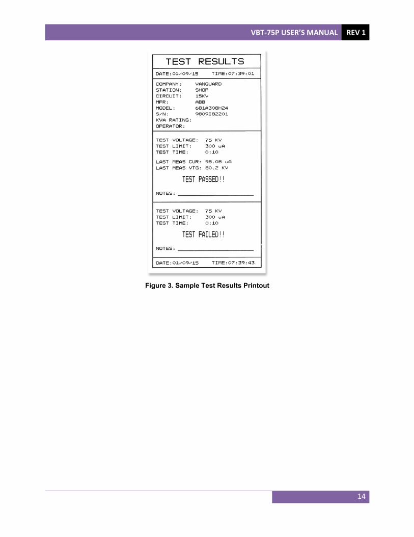
Press the [1] key (YES) to print the test results. A sample test results printout is shown in Figure 3.
PRINT TEST RESULTS?1.YES 2.NO
TEST COMPLETE 75KV 5Sec 300 μA
>>> FAIL <<<
TEST COMPLETE 75KV 5Sec 300 μA
>>> PASS <<<
TEST IN PROGRESS 74.9KV 186 μA
Time: 00:03
PRESS RED SWITCH
TO START TEST.

REV 1 VBT-75P USER’S MANUAL
13
j. The test results will be printed, and the following screen will be displayed:
Press the [1] key (YES) to keep the test reading.
k. The following screen will be displayed:
Press any key to continue.
l. The following screen will be displayed:
Press the [2] key (NO).
m. The following screen will be displayed:
Press the [1] key (YES) to save the test record.
n. The following screen will be displayed:
Press any key to return to the "START-UP" menu.
RECORD NUMBER 1 HAS BEEN SAVED!
SAVE THIS RECORD? 1.YES 2.NO
RUN ANOTHER TEST? 1.YES 2.NO
TEST SAVED
KEEP THIS READING?1.YES 2.NO
VBT-75P USER’S MANUAL REV 1
14
Figure 3. Sample Test Results Printout

REV 1 VBT-75P USER’S MANUAL
15
3.5 Printing a Directory of Test Records Stored in the VBT-75P's Memory You can print a directory of all the test records stored in the VBT-75P's Flash EEPROM using the steps below:
a. Start from the "START-UP" menu:
Press the [2] key (SETUP).
b. The following screen will be displayed:
Press the [3] key (RESTORE RECORD).
c. The following screen will be displayed:
Press the [2] key (DIRECTORY).
d. The following screen will be displayed:
1. PRINT DIRECTORY
Press the [1] key to print the test record directory on the unit's built-in thermal printer. The following screen will be displayed:
Press the [1] key to print a full directory listing of all the test records stored in the unit's Flash EEPROM. The directory listing will be printed on the thermal printer and you will be returned to the "START-UP" menu.
PRINT DIRECTORY 1.FULL DIRECTORY 2.SHORT DIRECTORY
1.PRINT DIRECTORY 2.SCROLL DIRECTORY
1.RESTORE RECORD 2.DIRECTORY 3.ERASE RECORDS
1.ENTER ID 2.REVIEW RECORD 3.RESTORE RECORD 4.NEXT PAGE
1.RUN TEST 03/16/152.SETUP 10:10:10
VBT-75P USER’S MANUAL REV 1
16
Press the [2] key to print a short directory listing of the stored test records. The short directory option prints the last 10 records stored in the unit's Flash EEPROM. The short directory listing will be printed on the thermal printer and you will be returned to the "START-UP" menu.
A sample directory printout is shown in figure x.
2. SCROLL DIRECTORY
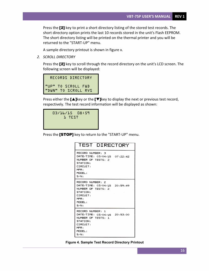
Press the [2] key to scroll through the record directory on the unit's LCD screen. The following screen will be displayed:
Press either the []key or the []key to display the next or previous test record, respectively. The test record information will be displayed as shown:
Press the [STOP] key to return to the "START-UP" menu.
Figure 4. Sample Test Record Directory Printout
03/16/15 08:591 TEST
RECORDS DIRECTORY "UP" TO SCROLL FWD "DWN" TO SCROLL RVS

REV 1 VBT-75P USER’S MANUAL
17
3.6 Reviewing a Test Record If you have just performed a test or just restored a test record from the unit's internal memory, it will be stored in the unit's temporary working memory. You can review the test record stored in the working memory by following the steps below:
a. Start from the "START-UP" menu:
Press the [2] key (SETUP).
b. The following screen will be displayed:
Press the [2] key (REVIEW RECORD).
c. The following screen will be displayed
Press the [1] key (SCROLL TEST RECORD) if you would like to review the test record in the working memory on the unit's LCD screen. Continue to step d.
Press the [2] key (PRINT TEST RECORD) to print the test record in the working memory on the unit's built-in thermal printer. The test record will be printed, and you will be returned to the "START-UP" menu.
d. The following screen will be displayed:
Press any key to continue.
RECORD ID INFO:
REVIEW RECORD 1.SCROLL TEST RECORD 2.PRINT TEST RECORD
1.ENTER ID 2.REVIEW RECORD 3.RESTORE RECORD 4.NEXT PAGE
1.RUN TEST 03/16/152.SETUP 10:10:10

VBT-75P USER’S MANUAL REV 1
18
e. The following screen will be displayed:
Press any key to continue.
f. The following screen will be displayed:
Press the [STOP] key to return to the "START-UP" menu.
TEST NUMBER: 175KV 5Sec 300μA 185 μA AT 74.9KV TEST PASSED!
1 TESTS 03/16/15 08:59:56

REV 1 VBT-75P USER’S MANUAL
19
3.7 Restoring a Test Record Follow the steps below to restore a test record from the VBT-75P's Flash EEPROM to the working memory:
a. Start from the “START-UP” menu:
Press the [2] key (SETUP).
b. The following screen will be displayed:
Press the [3] key (RESTORE RECORD).
c. The following screen will be displayed:
Press the [1] key (RESTORE RECORD).
d. The following screen will be displayed:
1. ENTER RECORD NUMBER
If you know the record number that you would like to restore, press the [1] key (ENTER RECORD NUMBR) . The following screen will be displayed:
Type the record number using the keypad and then press the [ENTER] key. The following screen will be displayed:
RESTORE RECORD NUMBER:
RESTORE RECORD
1.ENTER RECORD NUMBR 2.SCROLL TO SELECT
1.RESTORE RECORD 2.DIRECTORY 3.ERASE RECORDS
1.ENTER ID 2.REVIEW RECORD 3.RESTORE RECORD 4.NEXT PAGE
1.RUN TEST 03/16/152.SETUP 10:10:10

VBT-75P USER’S MANUAL REV 1
20
Press any key to continue. Continue to step c of section 3.6.
2. SCROLL TO SELECT
Press the [2] key (SCROLL TO SELECT) if you would like to scroll through a directory of the stored test records. The following screen will be displayed:
Press either the []key or the []key to display the next or previous test record, respectively. The test record information will be displayed as shown:
When you have located the test record that you would like to restore, press the [ENTER] key. The following screen will be displayed:
Press any key to continue. Continue to step c of section 3.6.
RECORD RESTORED!
03/16/15 08:591 TEST
RECORDS DIRECTORY "UP" TO SCROLL FWD "DWN" TO SCROLL RVS
RECORD RESTORED!

REV 1 VBT-75P USER’S MANUAL
21
3.8 Deleting Test Records Follow the steps below to delete one or more test records from the VBT-75P's Flash EEPROM:
a. Start from the "START-UP" menu:
Press the [2] key (SETUP).
b. The following screen will be displayed:
Press the [3] key (RESTORE RECORD).
c. The following screen will be displayed:
Press the [3] key (ERASE RECORDS).
d. The following screen will be displayed:
1. ERASE SINGLE REC.
Press the [1] key if you would like to erase a single record. The following screen will be displayed:
Type the record number to be erased and press the [ENTER] key.
ERASE RECORD NUMBER:
ERASE RECORD 1.ERASE SINGLE REC. 2.ERASE ALL RECORDS
1.RESTORE RECORD 2.DIRECTORY 3.ERASE RECORDS
1.ENTER ID 2.REVIEW RECORD 3.RESTORE RECORD 4.NEXT PAGE
1.RUN TEST 03/16/152.SETUP 10:10:10
VBT-75P USER’S MANUAL REV 1
22
NOTES
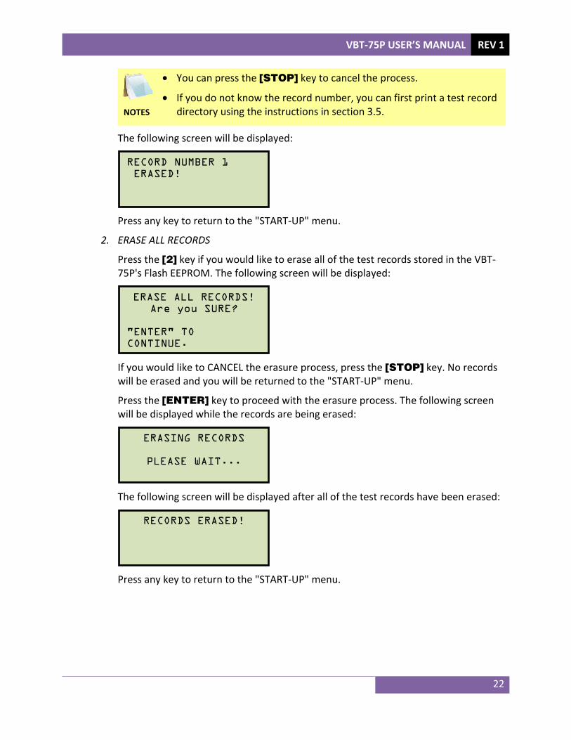
• You can press the [STOP] key to cancel the process.
• If you do not know the record number, you can first print a test record directory using the instructions in section 3.5.
The following screen will be displayed:
Press any key to return to the "START-UP" menu.
2. ERASE ALL RECORDS
Press the [2] key if you would like to erase all of the test records stored in the VBT-75P's Flash EEPROM. The following screen will be displayed:
If you would like to CANCEL the erasure process, press the [STOP] key. No records will be erased and you will be returned to the "START-UP" menu.
Press the [ENTER] key to proceed with the erasure process. The following screen will be displayed while the records are being erased:
The following screen will be displayed after all of the test records have been erased:
Press any key to return to the "START-UP" menu.
RECORDS ERASED!
ERASING RECORDS
PLEASE WAIT...
ERASE ALL RECORDS!Are you SURE?
"ENTER" TO CONTINUE.
RECORD NUMBER 1 ERASED!

1520 S. Hellman Ave • Ontario, CA 91761 • USA
Phone: 909-923-9390 • Fax: 909-923-9391 www.vanguard-instruments.com
Copyright © 2015 by Vanguard Instruments Company, Inc.
VBT-75P User’s Manual • Revision 1.0 • March 16, 2015 • TA