Embed Size (px)
Citation preview
http://www.3com.com/
Part Number 900-0499-01 Rev AAPublished March 2008
VCX™
Administration Guide
■ VCX IP Telephony Solution
■ VCX Telephones and Attendant Console
■ CDR Reporting Application
Convergence Applications SuiteSystem Release 8.0

3Com Corporation350 Campus Drive Marlborough, MA 01752-3064
Copyright © 2002–2008, 3Com Corporation. All rights reserved. No part of this documentation may be reproduced in any form or by any means or used to make any derivative work (such as translation, transformation, or adaptation) without written permission from 3Com Corporation.
3Com Corporation reserves the right to revise this documentation and to make changes in content from time to time without obligation on the part of 3Com Corporation to provide notification of such revision or change.
3Com Corporation provides this documentation without warranty, term, or condition of any kind, either implied or expressed, including, but not limited to, the implied warranties, terms, or conditions of merchantability, satisfactory quality, and fitness for a particular purpose. 3Com may make improvements or changes in the product(s) and/or the program(s) described in this documentation at any time.
If there is any software on removable media described in this documentation, it is furnished under a license agreement included with the product as a separate document, in the hardcopy documentation, or on the removable media in a directory file named LICENSE.TXT or !LICENSE.TXT. If you are unable to locate a copy, please contact 3Com and a copy will be provided to you.
UNITED STATES GOVERNMENT LEGENDS:
If you are a United States government agency, then this documentation and the software described herein are provided to you subject to the following:
United States Government Legend: All technical data and computer software is commercial in nature and developed solely at private expense. Software is delivered as Commercial Computer Software as defined in DFARS 252.227-7014 (June 1995) or as a commercial item as defined in FAR 2.101(a) and as such is provided with only such rights as are provided in 3Com’s standard commercial license for the Software. Technical data is provided with limited rights only as provided in DFAR 252.227-7015 (Nov 1995) or FAR 52.227-14 (June 1987), whichever is applicable. You agree not to remove or deface any portion of any legend provided on any licensed program or documentation contained in, or delivered to you in conjunction with guide.
Unless otherwise indicated, 3Com registered trademarks are registered in the United States and may or may not be registered in other countries.
3Com and the 3Com logo are registered trademarks of 3Com Corporation. VCX is a trademark of 3Com Corporation.
Microsoft and Windows are either registered trademarks or trademarks of Microsoft Corporation in the United States and/or other countries. Oracle is a registered trademark of Oracle Corporation.
Other brand and product names may be registered trademarks or trademarks of their respective holders.
CONTENTS
ABOUT THIS GUIDE
Conventions 12Related Documentation 13Comments 13
1 VCX SYSTEM CONFIGURATION OVERVIEW
Network-based Telephony 16VCX Software Components 17VCX Hardware Configurations 19
Single-Site Configurations 20Multi-Site Configurations 20
VCX Configuration Tasks 22VCX Connect System Configuration 26
VCX Connect Sample Configuration Settings 27Viewing the Event Logs 28About VCX Administrator Passwords 30
2 ACCESSING THE CENTRAL MANAGER USER INTERFACE
Central Manager Overview 34Accessing a VCX Site through the Central Manager 34
VCX Administrator Access Accounts 37Using the Graphical User Interface 40Modifying the Web Session Timeout Value 42Modifying Site Names through the Central Manager 43
4
3 USING THE GLOBAL DIRECTORY
Global Directory Overview 46Configuring the Global Directory 48
Directly Adding a User Directory to the Global Directory 48Updating a Directory Reference on a Regional Office 50Removing a Directory Reference on a Regional Office 51Listing Regional Offices in a Global Directory 52Configuring Data Collection Frequency 53Manually Resynchronizing the Global Directory 54Manually Loading a Global Directory Database 55Uploading a User Directory to Multiple Regional Offices 55Global Directory Requirements for Replicated Regions with Branch Offices 56
Searching for End Users through Global Directory 59Locating Global Directory Log Files 61
4 CONFIGURING VCX USERS
Accessing User Configuration Options 64Viewing All Users 65
Managing User Profiles 66Using the Users Search Tool 67
Viewing the Phone Book 67
5 CONFIGURING SERVICES
Configuring Class of Service 70Configuring Class of Service Elements 72
Configuring Type of Service 72Configuring Emergency Services 77
Emergency Calling Considerations for Roaming Users 79Managing ERLs 80Deleting ERLs 82Managing IP Address Ranges for an ERL 82Managing Emergency Numbers for an ERL 84Managing Emergency Gateways for an ERL 85Managing Emergency Lines for an ERL 86Adding or Editing the Emergency Defaults 89
5
6 MANAGING VCX PHONE PROFILES AND EXTENSIONS
Accessing Phone Configuration Options 92Managing Phone Profiles 93
VCX Connect Sample Phone Profiles 94Creating a Phone Profile 95Editing a Phone Profile 96Viewing Phone Profile Member Phones 96Deleting a Phone Profile 97Cloning a Phone Profile 98
Managing Phone Extensions 98Adding Phone Extensions 99Modifying a Phone Extension 99Deleting a Phone Extension 100
Managing Phone Extension Assignments 100Assigning a Phone Extension to a User 100Unassigning a Phone Extension 102User Roaming Services 103
Modifying a User’s Phone Settings 104Viewing Phone Registration Information 106Viewing Call History 108Configuring Media Access Control 110Configuring an Attendant Console 110
Supported Attendant Console Feature Buttons 111Managing Attendant Consoles 112Attendant Console Busy Lamp Flash Descriptions 112
7 VCX DATA SYNCHRONIZATION
About IP Telephony and IP Messaging Data Synchronization 114Data Synchronization and Phone Profiles 116
System Data Synchronization 117User Data Synchronization 118
Data Synchronization and Logging 121
8 CONFIGURING TELEPHONE COMMUNICATION SETTINGS
3Com Telephone Configuration 1243Com Telephone Local User Interface Menus 125
6
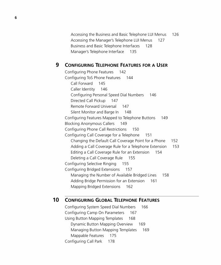
Accessing the Business and Basic Telephone LUI Menus 126Accessing the Manager’s Telephone LUI Menus 127Business and Basic Telephone Interfaces 128Manager’s Telephone Interface 135
9 CONFIGURING TELEPHONE FEATURES FOR A USER
Configuring Phone Features 142Configuring ToS Phone Features 144
Call Forward 145Caller Identity 146Configuring Personal Speed Dial Numbers 146Directed Call Pickup 147Remote Forward Universal 147Silent Monitor and Barge In 148
Configuring Features Mapped to Telephone Buttons 149Blocking Anonymous Callers 149Configuring Phone Call Restrictions 150Configuring Call Coverage for a Telephone 151
Changing the Default Call Coverage Point for a Phone 152Adding a Call Coverage Rule for a Telephone Extension 153Editing a Call Coverage Rule for an Extension 154Deleting a Call Coverage Rule 155
Configuring Selective Ringing 155Configuring Bridged Extensions 157
Managing the Number of Available Bridged Lines 158Adding Bridge Permission for an Extension 161Mapping Bridged Extensions 162
10 CONFIGURING GLOBAL TELEPHONE FEATURES
Configuring System Speed Dial Numbers 166Configuring Camp On Parameters 167Using Button Mapping Templates 168
Dynamic Button Mapping Overview 169Managing Button Mapping Templates 169Mappable Features 175
Configuring Call Park 178
7
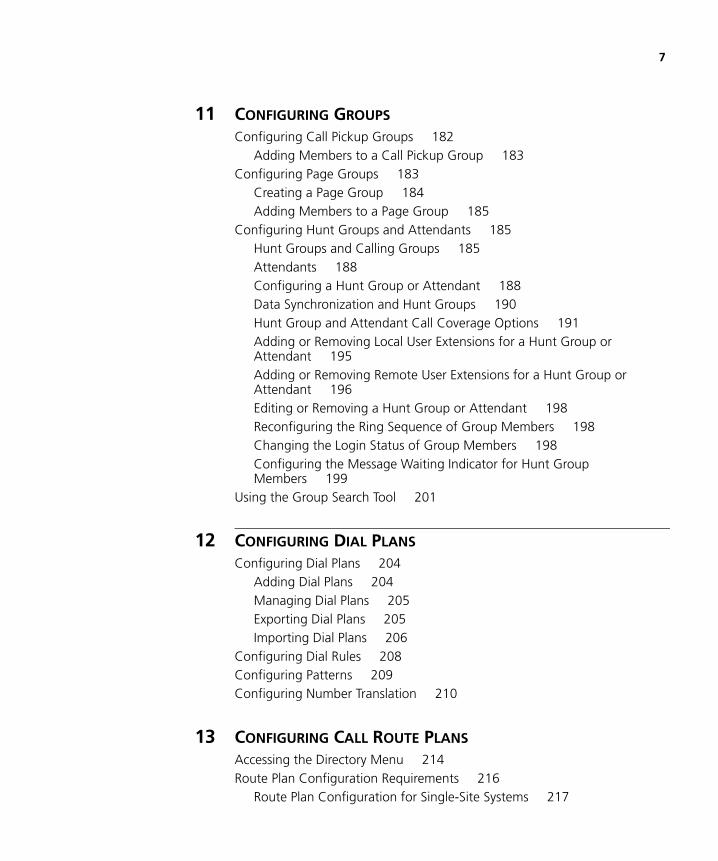
11 CONFIGURING GROUPS
Configuring Call Pickup Groups 182Adding Members to a Call Pickup Group 183
Configuring Page Groups 183Creating a Page Group 184Adding Members to a Page Group 185
Configuring Hunt Groups and Attendants 185Hunt Groups and Calling Groups 185Attendants 188Configuring a Hunt Group or Attendant 188Data Synchronization and Hunt Groups 190Hunt Group and Attendant Call Coverage Options 191Adding or Removing Local User Extensions for a Hunt Group or Attendant 195Adding or Removing Remote User Extensions for a Hunt Group or Attendant 196Editing or Removing a Hunt Group or Attendant 198Reconfiguring the Ring Sequence of Group Members 198Changing the Login Status of Group Members 198Configuring the Message Waiting Indicator for Hunt Group Members 199
Using the Group Search Tool 201
12 CONFIGURING DIAL PLANS
Configuring Dial Plans 204Adding Dial Plans 204Managing Dial Plans 205Exporting Dial Plans 205Importing Dial Plans 206
Configuring Dial Rules 208Configuring Patterns 209Configuring Number Translation 210
13 CONFIGURING CALL ROUTE PLANS
Accessing the Directory Menu 214Route Plan Configuration Requirements 216
Route Plan Configuration for Single-Site Systems 217

8
Route Plan Configuration for Multi-site Systems 219Route Configuration to a Gateway 226Route Configuration for Voicemail and Music on Hold 228
Managing Route Plans 234Adding a Route Plan 236Using the Route Plan Wizard 236Editing a Route Plan 237Deleting a Route Plan 237
Managing Routes 238Adding, Editing, or Deleting Routes 238Assigning or Removing End Points for a Route 239Editing Priorities of End Points Assigned to a Route 239Managing Out Dial Patterns for a Route 239
Managing End Points 240Adding or Removing an Out Dial Pattern for an End Point 241
Managing Trusted End Points 242Managing Out Dial Patterns 243Configuring Patterns 244
14 MANAGING ADVANCED ROUTING OPTIONS
Managing Requestors 246Managing Holidays 246Managing Week Day Bands 247Managing Day Time Bands 247Managing Calendar Bands 248Configuring Number Translation Patterns 249
Understanding Translation Algorithms 249Adding a Number Translation Pattern 250Editing Number Translation Patterns 250Deleting Number Translations 251
15 CONFIGURING THE CALL REPORTS APPLICATION
Call Detail Records Overview 254Accessing the Call Reports Application 255Downloading CDR Data 256
Retrieving VCX CDRs Manually 256Retrieving VCX CDRs Automatically 256

9
Managing the CDR Display and Generating Reports 257Changing Configuration Preferences 257Uninstalling the Call Reports Application 259
INDEX

10

ABOUT THIS GUIDE
This guide describes how to configure 3Com® VCX IP Telephony Solution software. VCX software runs on VCX Connect Communications servers, VCX V6000 platforms, and V6000 and V6100 Integrated Branch Communications Platforms.
This guide describes how to configure and maintain the following VCX™ IP Telephony Solution components:
■ VCX IP Telephony Solution server software
■ 3Com Telephones and Attendant Console
■ VCX CDR Reporting Application software
This guide is for operators and administrators of the system and assumes the reader has a thorough understanding of telecommunications, VoIP technology, and network and system administration operation.
Release notes are issued with some products. If the information in the release notes differs from the information in this guide, follow the instructions in the release notes.

12 ABOUT THIS GUIDE
Conventions Table 1 and Table 2 list conventions that are used throughout this guide.
Table 1 Notice Icons
Icon Notice Type Description
Information note Information that describes important features or instructions
Caution Information that alerts you to potential loss of data or potential damage to an application, system, or device
Warning Information that alerts you to potential personal injury
Table 2 Text Conventions
Convention Description
Screen displays This typeface represents information as it appears on the screen.
Syntax The word “syntax” means that you must evaluate the syntax provided and then supply the appropriate values for the placeholders that appear in angle brackets. Example:
To enable RIPIP, use the following syntax:
SETDefault !<port> -RIPIP CONTrol = Listen
In this example, you must supply a port number for <port>.
Commands The word “command” means that you must enter the command exactly as shown and then press Return or Enter. Commands appear in bold. Example:
To remove the IP address, enter the following command:
SETDefault !0 -IP NETaddr = 0.0.0.0
Words in italics Italics are used to:
■ Emphasize a point.
■ Denote a new term at the place where it is defined in the text.
■ Identify menu names, menu commands, and software button names. Examples:
From the Help menu, select Contents.
Click OK.
Related Documentation 13
Related Documentation
The 3Com documentation set contains additional information about the products in this release that are a part of or support the 3Com Convergence Applications Suite.
For documentation on VCX IP Telephony and Messaging, related application software, and hardware, open a browser and navigate to this location: http://csoweb4.3com.com/VCX/vcx_doc.cfm
Comments Send e-mail comments about this guide or about any Voice product documentation to:
Include the following information with your comments:
■ Document title
■ Document part number (found on the front page)
■ Page number
■ Your name and organization (optional)
Example:
VCX Administration GuidePart Number 900-0499-01 Rev AAPage 25
Please address all questions regarding the 3Com software to your authorized 3Com representative.

14 ABOUT THIS GUIDE

1
VCX SYSTEM CONFIGURATION OVERVIEWThe 3Com® VCX IP Telephony Solution delivers reliable, highly-scalable, comprehensive standards-based IP telephony for large, medium, and small enterprises. This chapter provides an overview of the VCX™ system and the steps required to enable devices to communicate in a VCX environment.
This chapter includes the following topics:
■ Network-based Telephony
■ VCX Software Components
■ VCX Hardware Configurations
■ VCX Configuration Tasks
■ VCX Connect System Configuration
■ Viewing the Event Logs
■ About VCX Administrator Passwords

16 CHAPTER 1: VCX SYSTEM CONFIGURATION OVERVIEW
Network-based Telephony
The VCX IP Telephony Solution merges telephony with networking by delivering business telephone service over a data network.
The VCX architecture provides a distributed call processing system using the SIP signalling protocol to establish voice, video, and text sessions between SIP phones and other SIP-compatible devices. The system can be deployed across enterprises in any topology from single-site campuses to highly distributed organizations with multiple branches.
VCX servers run the VCX operating system and host software components such as the Call Processor, VCX applications (such as IP Messaging), and configuration databases. SIP-enabled endpoints include VCX telephones and gateways that provide user access to the Public Switched Telephone Network (PSTN)
VCX system components can be installed in different configurations according to the features required and the number of subscribers that must be supported. The system configuration determines the tasks you must perform to enable communication between components.
VCX Software Components describes the VCX software components.
VCX Hardware Configurations, describes the two basic VCX configurations, single-site and multi-site systems.
VCX Configuration Tasks describes the general tasks required to add users, assign phones to users, and enable communication between devices on your VCX system.
This Guide provides descriptions and configuration information for all VCX systems. VCX software release 8.0 introduces the VCX Connect platform. A VCX Connect system provides telephony services for up to 250 users in a single site. Other versions of VCX software can be deployed across multiple sites in region-branch configurations that can support thousands of users. Distinctions between the VCX Connect platform and the VCX enterprise platforms are noted where appropriate.

VCX Software Components 17
VCX Software Components
This section describes the individual software components in a VCX system.
A VCX system includes the following software services:
■ Call Processor — Performs call processing functions and generates Call Detail Records (CDRs).
■ Authentication and Directory Service — Performs the following tasks:
■ Authentication:
Authentication (for example, validating a username and password)
Authorization (for example, verifying a user is allowed to make an international call)
User-specific routing or translation (for example, processes a personal speed dial number)
■ Directory (routing and translation functions):
The routing function identifies, selects, and prioritizes all the possible routes for a given call.
The translation function manipulates the access number or URI as a call propagates through the system.
■ Accounting Service — Sends, exports, and manages CDRs.
■ SIP Phone Downloader — Loads an application image on to a 3Com phone, which enables SIP support on the phone.
■ Common Agent — Connects other software components and the VCX server operating system to the Enterprise Management Suite (EMS) or other SNMP-based network management tools.
■ Provisioning Service — Provides a web-based user interface for managing authentication and directory data.
■ Call Records Service — Stores CDRs received from the Accounting Service. Sometimes referred to as the Billing Server.
■ IP Messaging Service — Provides integrated voice messaging, fax, and e-mail capabilities, and advanced messaging features such as Find Me Follow Me call routing and text-to-speech e-mail reading. Also supports Global Voicemail Integration, which links regional and branch office IP Messaging servers through a universal mailbox
18 CHAPTER 1: VCX SYSTEM CONFIGURATION OVERVIEW
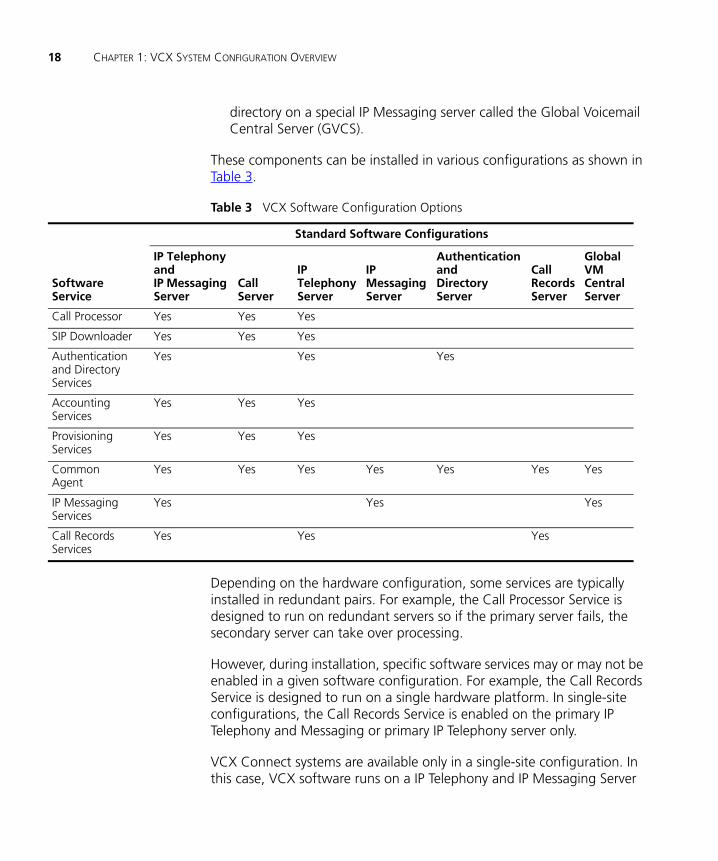
directory on a special IP Messaging server called the Global Voicemail Central Server (GVCS).
These components can be installed in various configurations as shown in Table 3.
Table 3 VCX Software Configuration Options
Depending on the hardware configuration, some services are typically installed in redundant pairs. For example, the Call Processor Service is designed to run on redundant servers so if the primary server fails, the secondary server can take over processing.
However, during installation, specific software services may or may not be enabled in a given software configuration. For example, the Call Records Service is designed to run on a single hardware platform. In single-site configurations, the Call Records Service is enabled on the primary IP Telephony and Messaging or primary IP Telephony server only.
VCX Connect systems are available only in a single-site configuration. In this case, VCX software runs on a IP Telephony and IP Messaging Server
Standard Software Configurations
SoftwareService
IP Telephony and IP Messaging Server
CallServer
IPTelephony Server
IPMessaging Server
AuthenticationandDirectory Server
Call Records Server
GlobalVMCentralServer
Call Processor Yes Yes Yes
SIP Downloader Yes Yes Yes
Authenticationand DirectoryServices
Yes Yes Yes
AccountingServices
Yes Yes Yes
ProvisioningServices
Yes Yes Yes
CommonAgent
Yes Yes Yes Yes Yes Yes Yes
IP MessagingServices
Yes Yes Yes
Call RecordsServices
Yes Yes Yes
VCX Hardware Configurations 19
(or pair of servers in a redundant configuration). In other words, all VCX services run on one machine.
VCX Hardware Configurations
This section briefly describes the basic hardware configurations that support VCX systems. Refer to the VCX Installation Guide for more information. Because VCX system software can be installed in a wide variety of hardware configurations, you must understand how your VCX system has been installed before you configure its components.
There are two basic configuration options, single-site and multi-site systems. The hardware servers in each option type run the VCX operating system and VCX services.
The following hardware platforms are available with VCX release 8.0 software preinstalled:
■ VCX Connect 100 Communications server (based on the V6100 hardware platform)
■ VCX Connect 200 Communications server (based on the IBM x3250 platform)
The following hardware platforms are available with VCX release 7.1 software:
■ VCX Enterprise Systems with IBM System x servers (x3650 and x3250).
■ V6000 Integrated Branch Communications server
■ V6100 Integrated Branch Communications server
The IBM x346, x345, x306m, and x306 servers have been discontinued. IBM System x servers are not available with VCX release 8.0 software and cannot be upgraded to the 8.0 release.
VCX Enterprise Systems with IBM System i servers, for example i520, i550, i570, i595, are available with VCX release 7.2 software. IBM System i servers are not available with VCX release 8.0 software and cannot be upgraded to the 8.0 release.
A future version of VCX release 8.0 software will support the VCX Enterprise hardware platforms.
The next two sections describe typical examples of single-site and multi-site configurations.

20 CHAPTER 1: VCX SYSTEM CONFIGURATION OVERVIEW
Single-SiteConfigurations
This section describes possible single-site configurations.
■ VCX Connect Systems
The VCX Connect 100 system and the VCX Connect 200 system can operate as either a single, non-redundant server or as a pair of redundant servers.
■ VCX Enterprise Systems
■ One Server
This configuration includes single, non-redundant server. The server runs the IP Telephony and IP Messaging configuration.
The Call Records Service is also enabled on the server.
■ One Pair of Servers
This configuration includes one pair of servers. The primary server and the secondary server both run the IP Telephony and IP Messaging configuration.
The Call Records Service is enabled on the primary server only.
■ Two Pair of Servers
This configuration includes two pairs of servers:
Two servers run the IP Telephony software configuration. The Call Records Service is enabled on the primary server only.
Two servers run the IP Messaging configuration.
■ Two servers run the IP Messaging configuration.
Multi-SiteConfigurations
Multi-site configurations can be configured several ways. This section describes possible multi-site configurations for VCX Enterprise Systems solutions. Your VCX system may differ from the described configurations.
A VCX Connect system provides telephony services for users in a single site. You can, however, use the Global Directory to link multiple VCX Connect sites. See Global Directory Overview for more information.
A VCX Enterprise System may include:
■ Multiple regional offices, all of which are self-contained but interconnected. Each office includes two servers each running the IP Telephony and IP Messaging configuration. One of the offices also has a Call Records Server which runs on a separate server and collects

VCX Hardware Configurations 21
billing information (CDRs) for all of the offices. There are no branch offices.
■ A single regional office that supports one or more branch offices.
■ Multiple regional offices, each of which supports one or more branch offices.
One of the regional offices contains:
■ Two servers running the Call Server configuration
■ One or two servers running the IP Messaging services configuration. The number of servers depends on whether the branch offices are configured with IP Messaging services or obtain that service from the regional office.
■ One server running the Authentication and Directory Server configuration
■ One server running the Call Records Server configuration
The other regional offices contain:
■ Two servers running the Call Server configuration
■ One or two servers running the IP Messaging services configuration. The number of servers depends on whether the branch offices are configured with IP Messaging services or obtain that service from the regional office.
■ One server running the Authentication and Directory Server configuration
■ Each branch office can operate with either a single IBM server or a 3Com V6000 (or V6100-series) Integrated Branch server.
■ The IBM server can run either the IP Telephony and IP Messaging configuration, or the IP Telephony configuration. The IP Telephony and IP Messaging configuration enables each branch office to have its own (local) IP Messaging service. The IP Telephony configuration requires that each branch office obtain IP Messaging services from the regional office (referred to as global messaging).
■ The 3Com V6000 Integrated Branch server runs the IP Telephony and IP Messaging configuration which enables local IP Messaging service.
With release 7.0 and higher, you can set up IP Messaging in a client/server configuration. An IP Messaging server can support up to 20 IP Messaging clients. One client can be dedicated to non-voice applications such as

22 CHAPTER 1: VCX SYSTEM CONFIGURATION OVERVIEW
Web provisioning, e-mail synchronization, and logging. The remaining clients can be dedicated to voice functions. This type of setup diverts the stream of voice traffic and improves the IP Messaging server performance. Clients should be located on the subnet with both management servers or have a minimum of 200 Mbps IP backbone on a dual subnet network configuration. See the IP Messaging Operations and System Administration Guide for details.
VCX Configuration Tasks
This section describes the basic tasks you must perform to create users, assign each user a phone, and enable communication between the phones. This section assumes that VCX software has been successfully installed, your network is functioning normally, and that you understand your VCX system configuration (single-site, multi-site, or VCX Connect system).
Communication in a VCX system is based on the Session Initiation Protocol (SIP). SIP is used to set up, maintain, and terminate connections (calls) between end points. These end points are SIP-enabled devices such as telephones, call processors, and gateways. Basic VCX configuration consists of identifying and configuring the end points in your VCX network, and setting up the rules that govern communication between the end points.
In general, VCX configuration includes the sequence of steps shown in Table 4. In a multi-site configuration, these steps must be performed at each site (regions and branches).
VCX Connect systems are typically preconfigured. See VCX Connect System Configuration. Depending on the level of preconfiguration, you may only need to perform the last step in Table 4 (configure each phone through its Telephone User Interface).
A VCX Connect system provides telephony services for users in a single site. You can, however, use the Global Directory to link multiple VCX Connect sites. See Global Directory Overview for more information.

VCX Configuration Tasks 23
Table 4 VCX Basic Configuration Steps
Step Purpose Reference
1 Access the VCX Administrator provisioning application through a web browser (Internet Explorer 6.0 or higher, or Firefox 2.0 or higher).
Enables configuration of your VCX system. Accessing a VCX Site through the Central Manager
2 Create dial string routing patterns.
A pattern defines the sequence of digits a user dials to call another site, and the sequence of digits dialed to reach an IP Messaging voicemail server or Music On Hold (MOH) server.
Configuring Patterns
3 Define end points.1 An end point is a device to which a call may be sent. End points include the VCX Call Processors (primary and secondary) that process local (network) calls, gateways that process out-of-network calls, and IP Messaging servers that manage voice mailboxes.
Managing End Points
4 Add routes.1 A route includes one or more end points. Route Plan Configuration Requirements
Managing Routes
5 Add route plans.1 A route plan associates a route with a dial string pattern.
Note: You can create a dial string pattern, define end points, add routes, and create a route plan by running the Route Plan Wizard.
Managing Route Plans
Using the Route Plan Wizard
6 Set up an outdial pattern to a route to strip off site-specific access codes.
Improves call routing efficiency (optional; useful, for example, in multi-site configurations or for routes to gateways).
Managing Out Dial Patterns for a Route
7 Examine the default Type of Service (ToS) configurations supplied with VCX software.
A ToS determines the features available on a VCX telephone (for example, call forwarding) and the default button mapping available on VCX Business and Manager’s telephones. If the supplied ToS configurations do not meet your needs, you can modify the existing configurations or create new ones.
Configuring Type of Service
8 Examine the default Class of Service (CoS) configurations supplied with VCX software.
A CoS determines what phone numbers a user is allowed to either call or receive. If the supplied CoS configurations do not meet your needs, you can modify the existing configurations or create new ones.
Configuring Class of Service
24 CHAPTER 1: VCX SYSTEM CONFIGURATION OVERVIEW
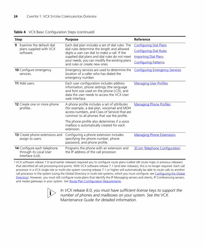
In VCX release 8.0, you must have sufficient license keys to support the number of phones and mailboxes on your system. See the VCX Maintenance Guide for detailed information.
9 Examine the default dial plans supplied with VCX software.
Each dial plan includes a set of dial rules. The dial rules determine the length and allowed digits a user can dial to make a call. If the supplied dial plans and dial rules do not meet your needs, you can modify the existing plans and rules or create new ones
Configuring Dial Plans
Configuring Dial Rules
Importing Dial Plans
Configuring Patterns
10 Configure emergency services.
Emergency services are used to determine the location of a caller who has dialed the emergency number.
Configuring Emergency Services
11 Add users. Each user configuration includes address information, phone settings (the language and font size used on the phone LCD), and data the user needs to access the VCX User web interface.
Managing User Profiles
12 Create one or more phone profiles.
A phone profile includes a set of attributes (for example, a dial plan, voicemail and MOH access numbers, and Class of Service) that are common to all phones that use the profile.
The phone profile also determines if a voice mailbox is automatically created for each extension.
Managing Phone Profiles
13 Create phone extensions and assign to users.
Configuring a phone extension includes specifying the phone number, phone password, and phone profile.
Managing Phone Extensions
14 Configure each telephone through its Local User Interface (LUI).
Programs the phone with an extension and the IP address of the call processor.
3Com Telephone Configuration
1 VCX software release 7.0 (and earlier releases) required you to configure route plans (called URI route maps in previous releases) that identified all call processing end points. With VCX software release 7.1 (and later releases), this is no longer required. Each call processor in a VCX single-site or multi-site system running release 7.1 or higher will automatically be able to route calls to another call processor in the system (using the Global Directory in multi-site systems, which you must configure; see Configuring the Global Directory). However, you must still configure route plans that identify the IP Messaging servers and clients, IP Conferencing servers, and media gateways in your system. See Route Plan Configuration Requirements.
Table 4 VCX Basic Configuration Steps (continued)
Step Purpose Reference

VCX Configuration Tasks 25
The steps in Table 4 are required to set up a VCX system with basic services. There are many other configuration options. For example, you can also enable the following features on your VCX system:
■ For multi-site systems, configure the Global Directory to enable site-to-site calling, and to enable users to see the names and extensions of users at other sites.
■ Configure an Attendant Console (VCX Model 3105).
■ Configure phone features such as call forwarding, silent monitoring, hunt groups, call park extensions, call bridging, and system speed dial numbers.
■ Set up user groups (for example, hunt groups and page groups).
■ Configure the Call Reports PC-based application to view Call Detail Records (CDRs) collected by the VCX Accounting service.
This Guide describes the VCX features you can configure through the VCX Administrator provisioning application. The steps required to configure a feature are described in the online Help provided with the application. If you are running a version of VCX software prior to the 8.0 release, online help is not available; instead, refer to the appropriate VCX Administration Guide.
Refer to the VCX Maintenance Guide for the following VCX system maintenance tasks:
■ Accounting and Call Records services configuration
■ Database maintenance, including backup and restore, and multi-master replication configuration
■ VCX Server management and reconfiguration
■ VCX configuration backup and restore
■ Uninterruptible Power Supply (UPS) management
■ Bulk user creation through the command line interface
■ VCX software upgrade and downgrade procedures
For VCX software release 8.0, you can also perform many maintenance tasks using the VCX System Administration web interface. Access to this interface is described in Viewing the Event Logs. See the VCX Maintenance Guide and the VCX System Administration web interface online Help for more information.

26 CHAPTER 1: VCX SYSTEM CONFIGURATION OVERVIEW
VCX Connect System Configuration
VCX Connect systems are shipped in a preconfigured state.
The installer runs the First Time Configuration web-based application wizard. The wizard enables the installer to specify network and application settings that enable a VCX Connect server to operate in the network.
The First Time Configuration wizard also enables the installer to configure telephony settings (for example, phone profile, dial plan, route plan, user profiles, and phone extensions). When the installer completes the First Time Configuration wizard, the VCX Connect server database is populated with the specified data.
The wizard provides two options for importing telephony data:
■ The installer can import a customer-supplied configuration file.
This file can include profile information for the actual users on your VCX system and the phone extension assigned to each user. In this case, you may only need to perform the last step in Table 4 (configure each phone through its Telephone User Interface) to complete your system setup.
■ The installer can import a 3Com-supplied sample configuration file.
This file includes sample data (for example, a set of phone profiles and four sample users with assigned extensions; see VCX Connect Sample Configuration Settings for more information). In this case, you can use some of the sample data (for example, one or more of the phone profiles) and use the VCX Administrator provisioning interface to perform other configuration tasks listed in (for example, add users and phone extensions).
You can perform any of the steps in Table 4 if you want to modify or add to your VCX Connect system. For example, you can use the VCX and IP Messaging provisioning interfaces to further configure the VCX Connect system by adding users, phone extensions, voice mailboxes, and configuring telephony features.

VCX Connect System Configuration 27
VCX Connect SampleConfiguration
Settings
After installation of VCX Connect server software, the installer can preconfigure the system by importing a 3Com-supplied sample configuration file.
The sample configuration data provides a fully functional VCX Connect system. While the intent of the sample data is to provide configuration examples, you can use the preconfigured elements in your VCX Connect system.
Table 5 describes the preconfigured elements in the 3Com-supplied sample configuration file.
3Com Corporation recommends that you do not modify these sample entries. Instead, keep them for reference and create new items based on the samples.
Table 5 3Com-Supplied Preconfigured Data for VCX Connect Systems
Element Description
Phone Profiles Provides six phone profiles: Standard, No-Voicemail, No-LongDistance, No-Voicemail-No-LongDistance, Fax-Modem, Executive. See VCX Connect Sample Phone Profiles for details.
Dial Plan Implements a 4-digit dial plan.
Telephone Extensions Configures four extensions: 1000, 1001, 1002, 1003.
All extensions are assigned to use the Standard phone profile.
Users Configures four users: Sample Receptionist, User1 Sample, User2 Sample, User3 Sample.
Voicemail Number Configures the voicemail access number 5000 in IP Messaging and specifies the number in each of the phone profiles that supports voicemail.
Music On Hold (MOH) Number
Configures the MOH number 5001 in IP Messaging and specifies the number in each of the phone profiles that supports MOH.
Number Translation Translates the number 0 to extension 1000, which is assigned to Sample Receptionist.
Call Park Range Configures a call park range of 800-899.
Route Plan Configures a route plan that includes a pattern, route, and end point. The route plan enables access to the IP Messaging service so that each sample extension can access a corresponding voice mailbox.

28 CHAPTER 1: VCX SYSTEM CONFIGURATION OVERVIEW
Viewing the Event Logs
This section describes how to use the VCX System Administration web interface to view logged events. This interface is available only for VCX software release 8.0 and requires admin account access (see VCX Administrator Access Accounts).
The VCX logging system audits the following events:
■ Login attempts to, and configuration changes made through, the following web interfaces:
■ VCX Administrator web provisioning interface
■ VCX User web provisioning interface
■ IP Messaging Administrator web provisioning interface
■ IP Messaging User web provisioning interface
■ Login attempts to the VCX operating system, both locally (through the console) and remotely (through the SSH protocol)
■ Commands issued from operating system shells
■ Startup and shutdown of system services
Note that both successful and failed login attempts are logged.
Each VCX server logs events for the VCX services running on the server. You need to know the IP address of a server to view its event log. You can determine the IP address of the server hosting any VCX service by logging in to the VCX primary call processor using the root account and entering the following command:
vcx-config-services --show
To view logged events through the VCX System Administration interface:
1 In a web browser address bar (Internet Explorer 6.0 or higher, or Firefox 2.0 or higher), enter the IP address of the VCX server whose events you want to monitor.
The 3Com VCX Networked Telephony Solution main page appears.
2 Click System Administration.
The System Administration page appears.
3 On the left side of the page, move the mouse pointer over the Event Logs menu and click the Event Logs option.
The Event Logs page appears. See Figure 1.
Viewing the Event Logs 29
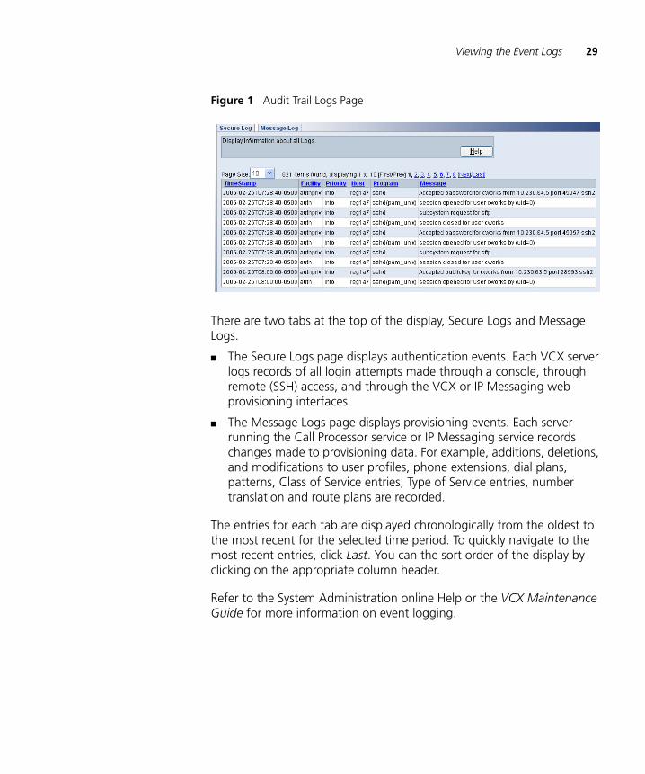
Figure 1 Audit Trail Logs Page
There are two tabs at the top of the display, Secure Logs and Message Logs.
■ The Secure Logs page displays authentication events. Each VCX server logs records of all login attempts made through a console, through remote (SSH) access, and through the VCX or IP Messaging web provisioning interfaces.
■ The Message Logs page displays provisioning events. Each server running the Call Processor service or IP Messaging service records changes made to provisioning data. For example, additions, deletions, and modifications to user profiles, phone extensions, dial plans, patterns, Class of Service entries, Type of Service entries, number translation and route plans are recorded.
The entries for each tab are displayed chronologically from the oldest to the most recent for the selected time period. To quickly navigate to the most recent entries, click Last. You can the sort order of the display by clicking on the appropriate column header.
Refer to the System Administration online Help or the VCX Maintenance Guide for more information on event logging.
30 CHAPTER 1: VCX SYSTEM CONFIGURATION OVERVIEW
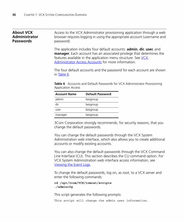
About VCX Administrator Passwords
Access to the VCX Administrator provisioning application through a web browser requires logging in using the appropriate account (username and password).
The application includes four default accounts: admin, dir, user, and manager. Each account has an associated privilege that determines the features available in the application menu structure. See VCX Administrator Access Accounts for more information.
The four default accounts and the password for each account are shown in Table 6.
3Com Corporation strongly recommends, for security reasons, that you change the default passwords.
You can change the default passwords through the VCX System Administration web interface, which also allows you to create additional accounts or modify existing accounts.
You can also change the default passwords through the VCX Command Line Interface (CLI). This section describes the CLI command option. For VCX System Administration web interface access information, see Viewing the Event Logs.
To change the default passwords, log on, as root, to a VCX server and enter the following commands:
cd /opt/3com/VCX/tomcat/scripts./admincfg
This script generates the following prompts:
This script will change the admin user information.
Table 6 Accounts and Default Passwords for VCX Administrator Provisioning Application Access
Account Name Default Password
admin besgroup
dir besgroup
user besgroup
manager besgroup
About VCX Administrator Passwords 31
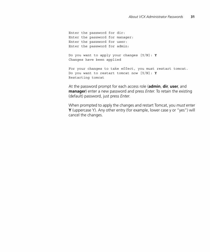
Enter the password for dir: Enter the password for manager: Enter the password for user: Enter the password for admin:
Do you want to apply your changes [Y/N]: Y Changes have been applied
For your changes to take effect, you must restart tomcat.Do you want to restart tomcat now [Y/N]: Y Restarting tomcat
At the password prompt for each access role (admin, dir, user, and manager) enter a new password and press Enter. To retain the existing (default) password, just press Enter.
When prompted to apply the changes and restart Tomcat, you must enter Y (uppercase Y). Any other entry (for example, lower case y or “yes”) will cancel the changes.

32 CHAPTER 1: VCX SYSTEM CONFIGURATION OVERVIEW
2
ACCESSING THE CENTRAL MANAGER USER INTERFACEThe Central Manager is a web portal that provides access to the VCX Administrator provisioning application, the IP Messaging provisioning application, the Global Directory, and a Site Data option that allows you to view VCX configuration information.
This chapter includes the following topics:
■ Central Manager Overview
■ Accessing a VCX Site through the Central Manager
■ Using the Graphical User Interface
■ Modifying the Web Session Timeout Value
■ Modifying Site Names through the Central Manager
Be sure to set your web browser preferences so that the cache is updated whenever you modify or view a new web page.

34 CHAPTER 2: ACCESSING THE CENTRAL MANAGER USER INTERFACE
Central Manager Overview
The Central Manager enables VCX system administrators to manage VCX system components using a web browser (Internet Explorer 6.0 or higher, or Firefox 2.0 or higher).
You can use the Central Manager to access the following management options:
■ The VCX Administrator provisioning application interface allows you to manage VCX servers anywhere in your VCX network.
The VCX Administrator provisioning application is described in this guide.
■ The IP Messaging provisioning application allows you to manage IP Messaging servers anywhere in your VCX network.
Refer to the IP Messaging Module Operations and System Administration Guide for IP Messaging provisioning information.
As shown in Figure 4, the Central Manager page also includes the following menu options:
■ The Global Directory option allows you to find configured users and their telephone extensions in any office.
The global directory is described in Chapter 3.
■ The Site Data option allows you to view VCX configuration information for a selected site and view the version of software running on each component of the VCX system. Note that this page is available only if you are logged in through the admin account (see VCX Administrator Access Accounts).
See the Central Manager online Help for more information.
Accessing a VCX Site through the Central Manager
This section describes how to access the VCX Administrator provisioning application through the Central Manager to manage either a regional or branch office.
You access the Central Manager through a web browser by entering an IP address in the browser’s address bar. The IP address required identifies the server hosting the Call Processor service (see VCX Software Components

Accessing a VCX Site through the Central Manager 35
for information on VCX services). Entering this IP address allows the VCX Administrator application to access the VCX provisioning database.
VCX systems are typically deployed in a redundant configuration which includes replicated databases. For VCX systems, database replication is the process of copying and maintaining database tables in a pair databases. Changes applied at the master site are captured and stored before being forwarded and applied at the other site.
When a database replication is enabled between two VCX servers, it is important to ensure data integrity. 3Com Corporation strongly recommends that you follow these guidelines for provisioning:
■ When two servers operate as a primary and secondary pair (for example, a redundant VCX Connect system), enter the IP address of the primary server to access the Central Manager.
■ When replication is set up between a regional office server and one or more branch office servers, enter the IP address of the regional primary server running the Call Processor service to access the Central Manager. Do not enter the IP address of a branch server.
In a multi-site system, the Call Processor service can run on one of the following VCX servers:
■ IP Telephony and IP Messaging Server
■ IP Telephony Server
■ Call Server
You can determine the IP address of the server hosting the Call Processor service (or any VCX service) by logging in to the VCX primary call processor using the root account and entering the following command:
To access the Central Manager:
1 From a web browser (Internet Explorer 6.0 or higher, or Firefox 2.0 or higher), enter the IP address of the server running the Call Processor service in your browser’s address bar.
The 3Com VCX Networked Telephony Solution main page appears (Figure 3), which includes the Central Management Console link. Depending on your VCX configuration and access account (see VCX Administrator Access Accounts), you may see other links, for example the VCX User Interface link and the VCX System Administration link.

36 CHAPTER 2: ACCESSING THE CENTRAL MANAGER USER INTERFACE
Note that you can display pages in one of several languages by clicking the appropriate link in the top right corner of the page.
Figure 2 3Com VCX Networked Telephony Solution Main Page
2 Click Central Management Console.
The Central Manager login page appears, see Figure 3.
Figure 3 Central Manager Login Page
3 Log in to the Central Manager using your assigned account (username and password). There are four default VCX administrator accounts: admin, dir, user, and manager (see VCX Administrator Access
Accessing a VCX Site through the Central Manager 37
Accounts). The default passwords for each account are listed in About VCX Administrator Passwords.
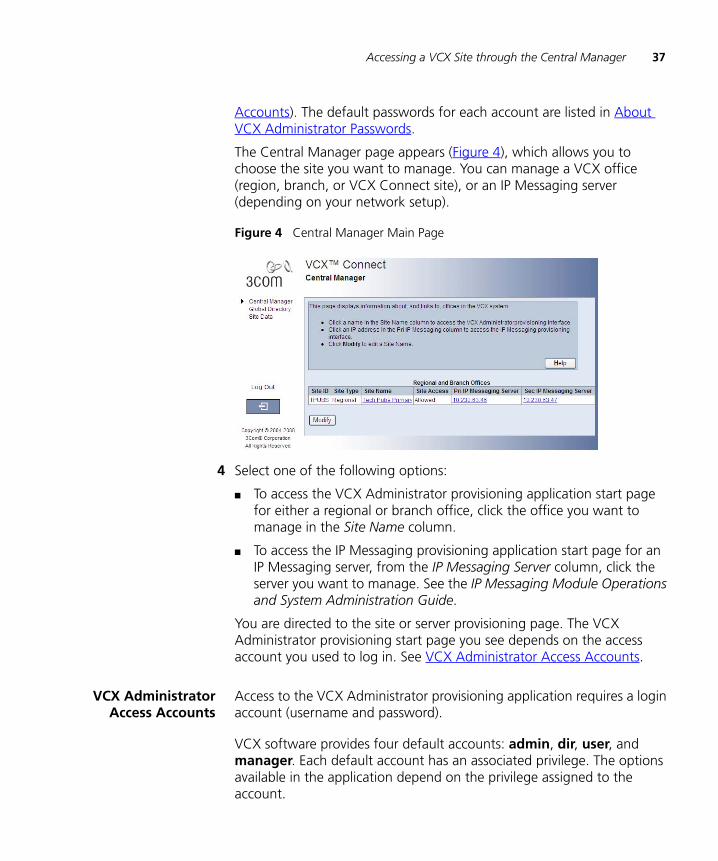
The Central Manager page appears (Figure 4), which allows you to choose the site you want to manage. You can manage a VCX office (region, branch, or VCX Connect site), or an IP Messaging server (depending on your network setup).
Figure 4 Central Manager Main Page
4 Select one of the following options:
■ To access the VCX Administrator provisioning application start page for either a regional or branch office, click the office you want to manage in the Site Name column.
■ To access the IP Messaging provisioning application start page for an IP Messaging server, from the IP Messaging Server column, click the server you want to manage. See the IP Messaging Module Operations and System Administration Guide.
You are directed to the site or server provisioning page. The VCX Administrator provisioning start page you see depends on the access account you used to log in. See VCX Administrator Access Accounts.
VCX AdministratorAccess Accounts
Access to the VCX Administrator provisioning application requires a login account (username and password).
VCX software provides four default accounts: admin, dir, user, and manager. Each default account has an associated privilege. The options available in the application depend on the privilege assigned to the account.
38 CHAPTER 2: ACCESSING THE CENTRAL MANAGER USER INTERFACE
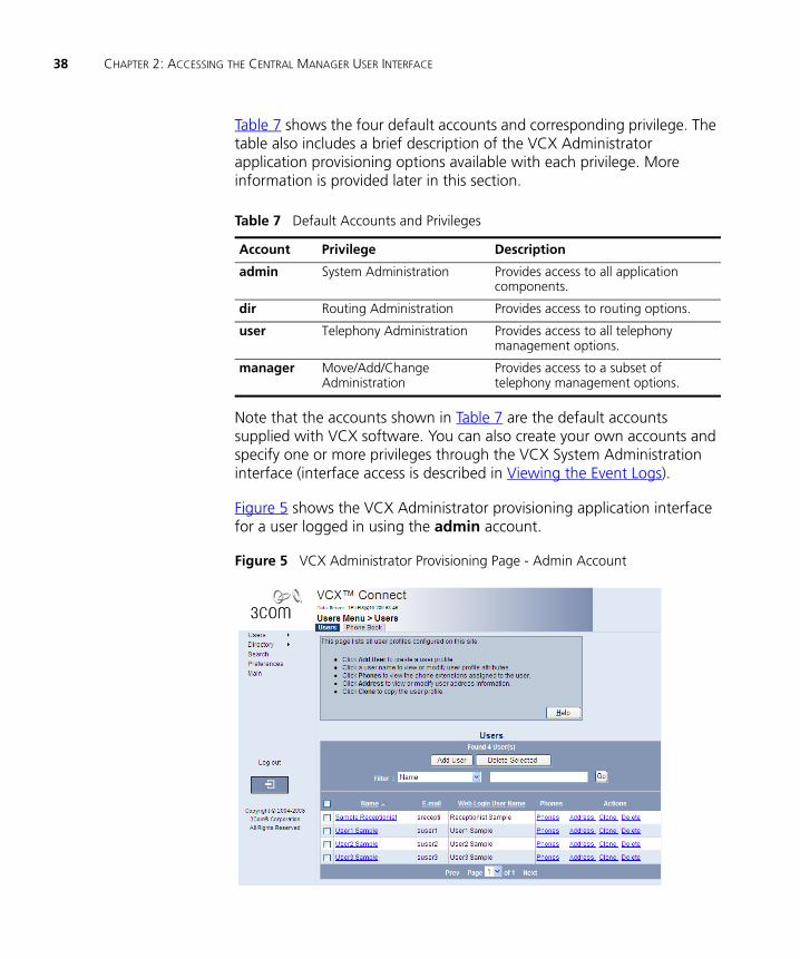
Table 7 shows the four default accounts and corresponding privilege. The table also includes a brief description of the VCX Administrator application provisioning options available with each privilege. More information is provided later in this section.
Note that the accounts shown in Table 7 are the default accounts supplied with VCX software. You can also create your own accounts and specify one or more privileges through the VCX System Administration interface (interface access is described in Viewing the Event Logs).
Figure 5 shows the VCX Administrator provisioning application interface for a user logged in using the admin account.
Figure 5 VCX Administrator Provisioning Page - Admin Account
Table 7 Default Accounts and Privileges
Account Privilege Description
admin System Administration Provides access to all application components.
dir Routing Administration Provides access to routing options.
user Telephony Administration Provides access to all telephony management options.
manager Move/Add/Change Administration
Provides access to a subset of telephony management options.
Accessing a VCX Site through the Central Manager 39
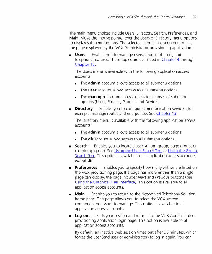
The main menu choices include Users, Directory, Search, Preferences, and Main. Move the mouse pointer over the Users or Directory menu options to display submenu options. The selected submenu option determines the page displayed by the VCX Administrator provisioning application.
■ Users — Enables you to manage users, groups of users, and telephone features. These topics are described in Chapter 4 through Chapter 12.
The Users menu is available with the following application access accounts:
■ The admin account allows access to all submenu options.
■ The user account allows access to all submenu options.
■ The manager account allows access to a subset of submenu options (Users, Phones, Groups, and Devices).
■ Directory — Enables you to configure communication services (for example, manage routes and end points). See Chapter 13.
The Directory menu is available with the following application access accounts:
■ The admin account allows access to all submenu options.
■ The dir account allows access to all submenu options.
■ Search — Enables you to locate a user, a hunt group, page group, or call pickup group. See Using the Users Search Tool or Using the Group Search Tool. This option is available to all application access accounts except dir.
■ Preferences — Enables you to specify how many entries are listed on the VCX provisioning page. If a page has more entries than a single page can display, the page includes Next and Previous buttons (see Using the Graphical User Interface). This option is available to all application access accounts.
■ Main — Enables you to return to the Networked Telephony Solution home page. This page allows you to select the VCX system component you want to manage. This option is available to all application access accounts.
■ Log out — Ends your session and returns to the VCX Administrator provisioning application login page. This option is available to all application access accounts.
By default, an inactive web session times out after 30 minutes, which forces the user (end user or administrator) to log in again. You can
40 CHAPTER 2: ACCESSING THE CENTRAL MANAGER USER INTERFACE
change the web session timeout value to extend or shorten the time allowed for inactive web sessions. See Modifying the Web Session Timeout Value.
Using the Graphical User Interface
This section describes the common set of interface options used on VCX provisioning pages.
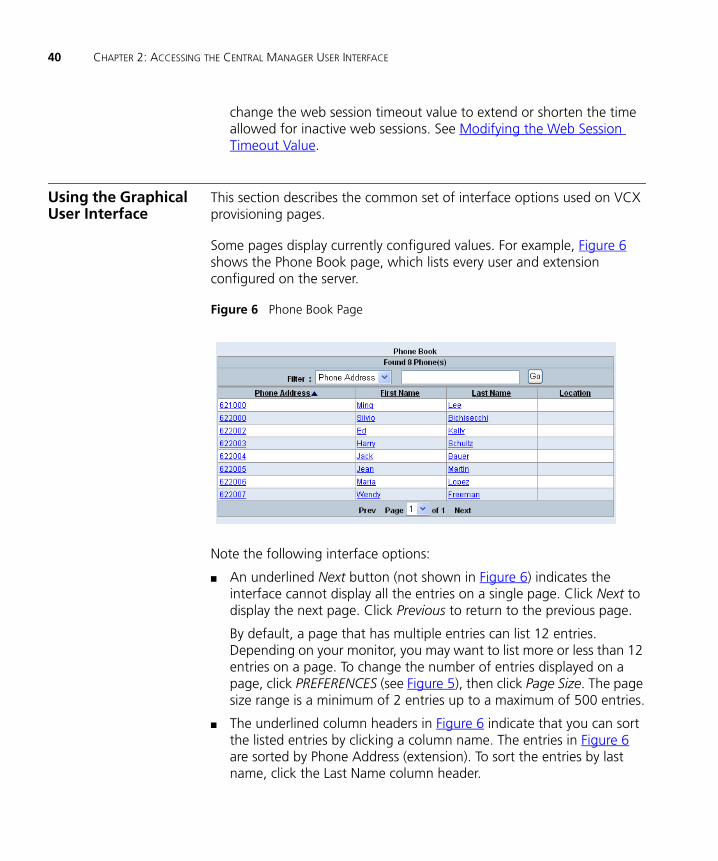
Some pages display currently configured values. For example, Figure 6 shows the Phone Book page, which lists every user and extension configured on the server.
Figure 6 Phone Book Page
Note the following interface options:
■ An underlined Next button (not shown in Figure 6) indicates the interface cannot display all the entries on a single page. Click Next to display the next page. Click Previous to return to the previous page.
By default, a page that has multiple entries can list 12 entries. Depending on your monitor, you may want to list more or less than 12 entries on a page. To change the number of entries displayed on a page, click PREFERENCES (see Figure 5), then click Page Size. The page size range is a minimum of 2 entries up to a maximum of 500 entries.
■ The underlined column headers in Figure 6 indicate that you can sort the listed entries by clicking a column name. The entries in Figure 6 are sorted by Phone Address (extension). To sort the entries by last name, click the Last Name column header.
Using the Graphical User Interface 41
■ You can also search for a particular entry by selecting a search option in the Filter drop down list (Extension, First Name, Last Name, or Location). Then, enter the appropriate search criteria in the Filter text box and click Go.
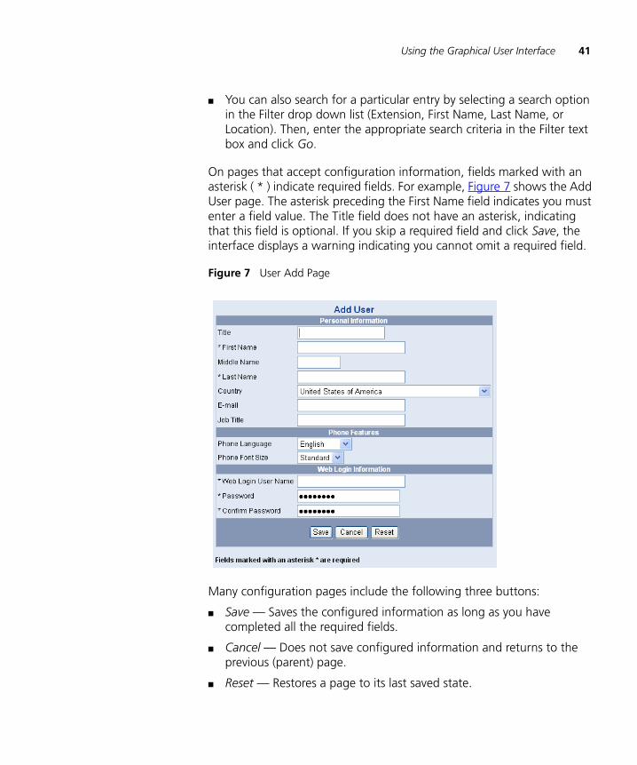
On pages that accept configuration information, fields marked with an asterisk ( * ) indicate required fields. For example, Figure 7 shows the Add User page. The asterisk preceding the First Name field indicates you must enter a field value. The Title field does not have an asterisk, indicating that this field is optional. If you skip a required field and click Save, the interface displays a warning indicating you cannot omit a required field.
Figure 7 User Add Page
Many configuration pages include the following three buttons:
■ Save — Saves the configured information as long as you have completed all the required fields.
■ Cancel — Does not save configured information and returns to the previous (parent) page.
■ Reset — Restores a page to its last saved state.
42 CHAPTER 2: ACCESSING THE CENTRAL MANAGER USER INTERFACE
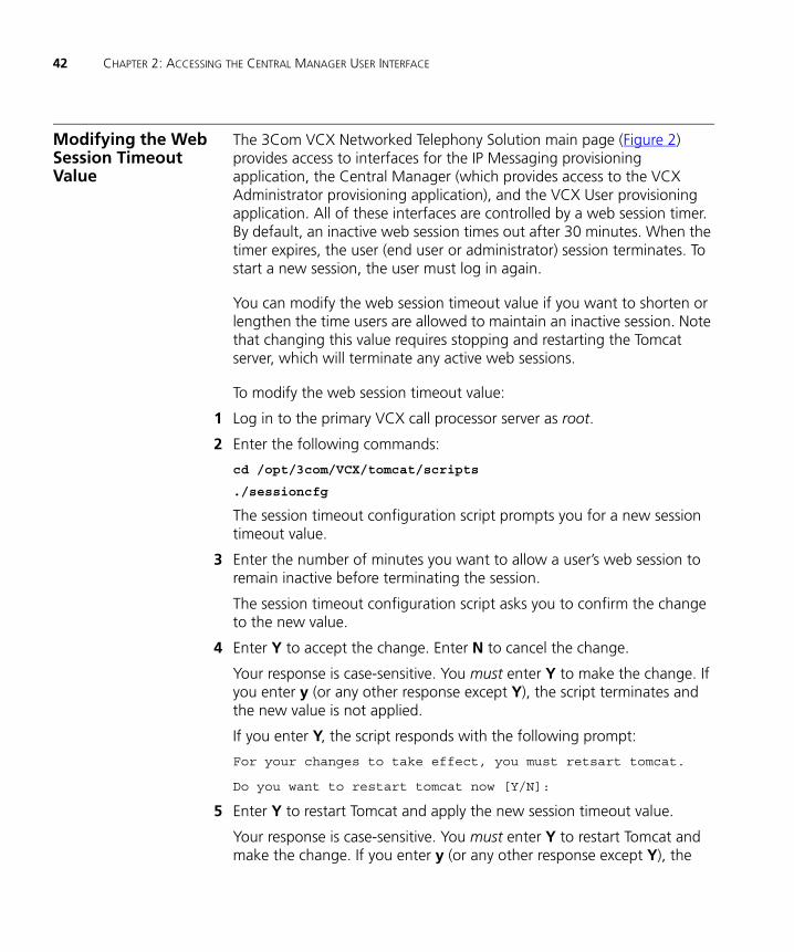
Modifying the Web Session Timeout Value
The 3Com VCX Networked Telephony Solution main page (Figure 2) provides access to interfaces for the IP Messaging provisioning application, the Central Manager (which provides access to the VCX Administrator provisioning application), and the VCX User provisioning application. All of these interfaces are controlled by a web session timer. By default, an inactive web session times out after 30 minutes. When the timer expires, the user (end user or administrator) session terminates. To start a new session, the user must log in again.
You can modify the web session timeout value if you want to shorten or lengthen the time users are allowed to maintain an inactive session. Note that changing this value requires stopping and restarting the Tomcat server, which will terminate any active web sessions.
To modify the web session timeout value:
1 Log in to the primary VCX call processor server as root.
2 Enter the following commands:
cd /opt/3com/VCX/tomcat/scripts
./sessioncfg
The session timeout configuration script prompts you for a new session timeout value.
3 Enter the number of minutes you want to allow a user’s web session to remain inactive before terminating the session.
The session timeout configuration script asks you to confirm the change to the new value.
4 Enter Y to accept the change. Enter N to cancel the change.
Your response is case-sensitive. You must enter Y to make the change. If you enter y (or any other response except Y), the script terminates and the new value is not applied.
If you enter Y, the script responds with the following prompt:
For your changes to take effect, you must retsart tomcat.
Do you want to restart tomcat now [Y/N]:
5 Enter Y to restart Tomcat and apply the new session timeout value.
Your response is case-sensitive. You must enter Y to restart Tomcat and make the change. If you enter y (or any other response except Y), the

Modifying Site Names through the Central Manager 43
script terminates, Tomcat is not stopped and restarted, and the new value is not applied.
Modifying Site Names through the Central Manager
You can change the site name of regional and branch offices using the Central Manager.
To edit a site name:
1 Access the Central Manager (see the previous section, Accessing a VCX Site through the Central Manager).
The Central Manager page appears.
2 Click Modify.
The regional and branch office site name fields become editable.
3 Modify a site name by editing the field value in the Site Name column.
4 Click Save.
The site name is updated.

44 CHAPTER 2: ACCESSING THE CENTRAL MANAGER USER INTERFACE

3
USING THE GLOBAL DIRECTORYConfiguring the Global Directory identifies different sites in a VCX system to each other. This integration allows users to make calls between sites and allows the user directory on one site to be visible to the users on another site.
This chapter includes the following topics:
■ Global Directory Overview
■ Configuring the Global Directory
■ Searching for End Users through Global Directory
■ Locating Global Directory Log Files

46 CHAPTER 3: USING THE GLOBAL DIRECTORY
Global Directory Overview
The Global Directory option on the Central Manager page (see the left side of Figure 4) allows you to search for configured users in any office linked to the Central Manager. You can search using first or last name, phone extension, or site ID or name. Once you find the user, you can launch the VCX Administrator provisioning interface on the server where the user is configured. This feature is useful in multi-site systems, where there are multiple regional offices and possibly branch offices associated with a regional office.
A VCX Connect system provides telephony services for users in a single site. You can, however, use the Global Directory to link multiple (maximum of six) VCX Connect sites. If you plan to link VCX Connect systems through the Global Directory, you must ensure that telephone extensions are unique among the linked systems. During the initial setup of a VCX Connect system (First Time Configuration), the installer can provision the system with four default users and extensions (1000-1003). You must modify or delete these default extensions on all but one of the VCX Connect systems you plan to link.
The Global Directory is also used in VCX version 7.1 (and higher) systems for call routing. Prior to version 7.1, you had to configure routes between each VCX call processing end point to enable calling in a multi-site system. Starting with version 7.1, VCX software can use the Global Directory on each call processor to make call routing decisions. See Route Plan Configuration Requirements for more information on routing. See topics in this section for information on setting up the Global Directory.
Figure 8 show the Global Directory page and shows the search results for all users whose first name contains the letter “j”.
For the discussion of the Global Directory in this chapter, you can consider regional offices to be either remote locations in a multi-site implementation of a VCX enterprise system or multiple linked locations in a VCX Connect system.
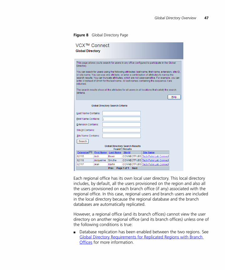
Global Directory Overview 47
Figure 8 Global Directory Page
Each regional office has its own local user directory. This local directory includes, by default, all the users provisioned on the region and also all the users provisioned on each branch office (if any) associated with the regional office. In this case, regional users and branch users are included in the local directory because the regional database and the branch databases are automatically replicated.
However, a regional office (and its branch offices) cannot view the user directory on another regional office (and its branch offices) unless one of the following conditions is true:
■ Database replication has been enabled between the two regions. See Global Directory Requirements for Replicated Regions with Branch Offices for more information.
48 CHAPTER 3: USING THE GLOBAL DIRECTORY
■ You run a script, config.sh, on one region to identify the other region you want to include in the first region’s global directory.
Configuring the Global Directory
The topics in this section describe the option for using the config.sh script to configure the global directory.
The topics use the example of the Boston, Chicago, and Los Angeles regional offices. Each regional office includes a pair of redundant VCX servers (primary and secondary).
For example, it is possible to have three regional offices (Boston, Chicago, and Los Angeles) and not allow any of them to see the other’s user directory. It is also possible to set up a global directory at the Boston regional office that includes the users in Chicago, but not allow the Chicago regional office see Boston’s user directory. You, the administrator, have complete control over how you want the user directories to be visible.
To run the config.sh script, you log on to one of the primary VCX regional servers. Some script options prompt you to identify another region by entering an IP address or hostname. The VCX server you log in to and the VCX servers you are asked to identify must be the servers running the Authentication and Directory service. You can determine the IP address of a service by logging in to a primary VCX server as root and entering the following command:
vcx-config-services --show
The command response shows the type of VCX system configuration and shows the IP addresses for all VCX services.
VCX version 7.1 multi-site systems rely on configuration of the Global Directory to enable call routing between regions. If you elect to hide the user directory in a region, you must configure a route plan on the other regions in the system to identify the hidden region. See Route Plan Configuration Requirements for information.
Directly Adding aUser Directory to the
Global Directory
To directly add a user directory to another regional office, use the config.sh script option 101, on the regional office you are logged on to. User directories can also be added indirectly by using the config.sh script, option 107, in which case user directories are “pushed” to other
Configuring the Global Directory 49
regional offices (see Uploading a User Directory to Multiple Regional Offices).
By directly adding a user directory from a regional office, you control which user directories you want to add to your server. For example, if at the Boston office you add Chicago’s user directory, Boston users can see Chicago’s user directory but Chicago can not see Boston’s user directory. Chicago users can not see Boston’s user directory until you add the Boston directory at the Chicago office.
The following example adds the Chicago user directory to the Boston regional office:
1 Log on to the primary VCX server in Boston using the cworks account and enter these commands:
cd /opt/3com/VCX/vcxdata/globaldir/bin
./config.sh
2 At the prompt, enter 101.
The Enter the Primary ROSCA IP Address or Hostname prompt appears.
3 Enter the hostname or IP address of the primary server at the remote regional office (in this example, the Chicago office) whose user directory you want to add.
The Enter the Secondary ROSCA IP Address or Hostname prompt appears.
4 Enter the hostname or IP address of the secondary server at the remote regional office (in this example, the Chicago office).
The Enter an Username for both Primary & Secondary ROCSA’s prompt appears.
5 Enter the username for the cworks account. The default is cworks but may be changed during installation.
The Enter Password prompt appears.
6 Enter the password for the cworks account after the asterisks (*). The default is cworks but may be changed during installation.
7 Press Enter.
The Re-type Password prompt appears.
8 Reenter the password for the cworks account after the asterisks (*).

50 CHAPTER 3: USING THE GLOBAL DIRECTORY
The Enter the Global Directory Input Path at ROCSA [/opt/3com/VCX/vcxdata/db/export] prompt appears, which lists the default path to the location of the regional user directory common file.
9 Press Enter.
3Com does not recommend changing this default directory path.
10 Press Enter to return to the main menu.
The Boston global directory information will be updated with the Chicago user directory once the user directory databases resynchronize, either automatically or manually (see Manually Resynchronizing the Global Directory on page 54).
Updating a DirectoryReference on aRegional Office
Use this option to update the IP address or hostname entry for a regional office. In the following example, the IP address for the Chicago office has changed so the Boston office must be updated.
1 Log on to the primary VCX server in Boston using the cworks account and enter these commands:
cd /opt/3com/VCX/vcxdata/globaldir/bin
./config.sh
The SELECT OPERATION prompt appears.
2 At the prompt, enter 104.
The Enter the Primary ROSCA IP Address or Hostname to Update prompt appears.
3 Enter the IP address of the primary server at the remote regional office (in this example, the Chicago office) whose IP address has changed.
The Enter the Secondary ROSCA IP Address or Hostname to Update prompt appears.
4 Enter the IP address of the secondary server at the remote regional office (in this example, the Chicago office).
The Enter an Username for both Primary & Secondary ROCSA’s to Update prompt appears.
5 Enter the username for the cworks account. The default is cworks but may be changed during installation.
The Do you want to Update Password [n/y] prompt appears.
6 The password cannot be updated from here. Enter n to continue.

Configuring the Global Directory 51
The Enter the Global Directory Input Path at ROCSA [/opt/3com/VCX/vcxdata/db/export] prompt appears, which lists the default path the regional user directory common file is located.
7 Press Enter.
3Com does not recommend changing this default directory path.
8 Press Enter to return to the main menu.
The Boston global directory information will be updated with the Chicago user directory when the user directory databases resynchronize, either automatically or manually (see Manually Resynchronizing the Global Directory).
Removing a DirectoryReference on aRegional Office
You can remove a regional directory from a regional office if the regional office moves, is closed, or if you no longer want users to see that directory. When you remove a regional user directory database, only the reference to that database is deleted from the specified server.
In the following example, the Chicago user directory is configured on regional offices in Boston and Los Angeles. The steps remove the Chicago user directory from the Boston regional office but maintain it on the Los Angeles regional office.
To remove a regional office from the global directory:
1 Log on to the primary VCX server in Boston using the cworks account and enter these commands:
cd /opt/3com/VCX/vcxdata/globaldir/bin
./config.sh
The SELECT OPERATION prompt appears.
2 At the prompt, enter 102.
The Enter the Primary ROSCA IP Address or Hostname to Delete prompt appears.
3 Enter the IP address of the primary server at the remote regional office (in this example, the Chicago office) that you want to remove.
A confirmation prompt appears, asking you to confirm removal.
4 Enter y to delete the regional office directory.
52 CHAPTER 3: USING THE GLOBAL DIRECTORY
The Chicago regional office user directory will be deleted from the Boston office’s global directory when the user directory databases resynchronize, either automatically or manually.
Listing RegionalOffices in a Global
Directory
You can use the config.sh script to list all of the peer regional offices whose user directories can be viewed on the server you are logged on to. You can also list the host regional office of a branch office.
Listing Peer Regional Offices from a Regional Office
In the following example, the Boston office is configured to view the user directories on regional offices in Chicago and Los Angeles.
To list all of the peer regional offices whose user directories can be viewed on the Boston office:
1 Log on to the primary VCX server in Boston using the cworks account and enter these commands:
cd /opt/3com/VCX/vcxdata/globaldir/bin
./config.sh
The SELECT OPERATION prompt appears.
2 At the prompt, enter 103.
The config.sh script lists the details for the Chicago and Los Angeles regional offices.
3 Press Enter.
If there is more than one regional office, the next one is listed; otherwise, you are returned to the main prompt.
Showing the Regional Offices from a Branch Office
You can display the regional office that hosts a branch office.
To list the host regional office of a branch office:
1 Log on to the primary VCX server of the branch office using the cworks account and enter these commands:
cd /opt/3com/VCX/vcxdata/globaldir/bin
./config.sh
The SELECT OPERATION prompt appears.
2 At the prompt, enter 103.
The config.sh script lists the details for a branch’s regional office.

Configuring the Global Directory 53
3 Press Enter.
You are returned to the main prompt.
Configuring DataCollection Frequency
You can specify how often you want a data collection to automatically occur at each regional office. Any new users that have been added or edits that have been made on a remote regional office are not visible on a local regional office until data is collected for each remote regional office.
A regional office collects user directory data for:
■ Each branch office that it hosts
■ Every phone configured on that regional office
■ Every remote regional office for which it is configured to collect user directory data.
By default, data collection happens every six hours (360 minutes). 3Com Corporation recommends that, if you have more than one regional office, you configure your data collection frequency to occur at least three times a day to ensure the databases are synchronized.
Branch office global directory configuration is automatically configured during installation and does not require any additional configuration. The branch office configuration tool is provided for any manual modifications that might be required.
Configuring Data Collection Frequency for a Regional Office
This procedure determines how often the Boston regional office collects data from its peer regional offices in Chicago and Los Angeles.
To configure the data collection frequency on a regional office:
1 Log on to the primary VCX server in Boston using the cworks account and enter these commands:
cd /opt/3com/VCX/vcxdata/globaldir/bin
./config.sh
2 At the prompt, enter 105.
3 At the prompt, enter (in minutes) the frequency at which you want the data collection to occur.
You are returned to the main menu.

54 CHAPTER 3: USING THE GLOBAL DIRECTORY
The user directory in Boston will automatically collect information from the Chicago and Los Angeles regions at the specified interval.
Configuring Data Collection Frequency at a Branch Office
This procedure determines how often a branch office collects user directory data from its host regional office.
To configure the data collection frequency on a branch office:
1 Log on to the primary VCX server of the branch office using the cworks account and enter these commands:
cd /opt/3com/VCX/vcxdata/globaldir/bin
./config.sh
2 At the prompt, enter 105.
3 At the prompt, enter (in minutes) the frequency at which you want the data collection to occur.
You are returned to the main menu.
The user directory on the branch office will automatically collect information from its host region at the specified interval.
ManuallyResynchronizing the
Global Directory
You can force a regional office to collect global directory database updates from its peer regional offices and its own database. The updated global directory is not immediately visible on the regional office phones, but it is visible on the branch office phones. To make the updated global directory immediately available on the regional office phones, see Manually Loading a Global Directory Database.
The following example resynchronizes the Boston global directory.
To manually resynchronize a regional office:
1 Log on to the primary VCX server in Boston using the cworks account and enter these commands:
cd /opt/3com/VCX/vcxdata/globaldir/bin
./config.sh
2 At the prompt, enter 106.
The global directory on the Boston office resynchronizes immediately.
3 Press Enter.
Configuring the Global Directory 55
You are returned to the main menu. To make the updated global directory immediately available on the Boston regional office phones, see Manually Loading a Global Directory Database.
Manually Loading aGlobal Directory
Database
You can load an updated global directory on a regional office so it is immediately visible on the regional office phones. This option is generally used after an updated global directory has been manually resynchronized.
In the previous section (Manually Resynchronizing the Global Directory), the global directory at the Boston office was resynchronized. To manually load this updated global directory database, log on to the primary VCX server in Boston using the cworks account and enter these commands:
cd /opt/3com/VCX/vcxdata/globaldir/bin
./forceGDBLoad.pl
Uploading a UserDirectory to Multiple
Regional Offices
You can push a user directory to all other configured regional offices so that data upload does not need to be performed individually at all the regional offices that have been added using option 101.
For example, Boston, Chicago, and Los Angeles have each been configured using option 101 so that users at each site have a global directory that includes users at the other two sites. If the Boston office adds or deletes users, the Chicago and Los Angeles offices would have to either automatically or manually resynchronize their user directory databases. Alternatively, the Boston office can upload its changes to both Chicago and Los Angeles.
To upload the user directory to all other deployed regional offices:
1 Log on to the primary VCX server in Boston using the cworks account and enter these commands:
cd /opt/3com/VCX/vcxdata/globaldir/bin
./config.sh
2 At the prompt, enter 107.
Boston’s global directory is uploaded to all other configured peer regional offices (in this example, Chicago and Los Angeles) immediately.
3 Press Enter.
You are returned to the main menu.

56 CHAPTER 3: USING THE GLOBAL DIRECTORY
Global DirectoryRequirements for
Replicated Regionswith Branch Offices
This section describes global directory configuration requirements when database replication is enabled between two regions, and each region includes branch offices.
If replication is enabled between two regions, the entries in the global directory depend on your location.
For example, Boston (R1) has two branch offices (R1B1 and R1B2) Chicago (R2) has two branch offices (R2B1 and R2B2). Database replication is enabled between R1 and R2.
■ The global directory on R1 includes users provisioned on R1, R1B1, R1B2, and R2.
■ The global directory on R2 includes users provisioned on R2, R2B1, R2B2, and R1.
Notice that the branch offices associated with the remote region are not included. For example, while the global directory for R1 does include users provisioned on R2, it does not include users provisioned on R2’s branches, R2B1 and R2B2.
Adding Remote Branches to a Regional Global Directory
To add remote branch users (in this example, R2B1 and R2B2) to the global directory for a local region (in this example, R1):
1 Log on to the primary VCX server in R1 using the cworks account and enter these commands:
cd /opt/3com/VCX/vcxdata/globaldir/bin
./config.sh
2 At the prompt, enter 101.
The Enter the Primary ROSCA IP Address or Hostname prompt appears.
3 Enter the hostname or IP address of the primary server at the remote regional office (in this example, R2) whose user directory you want add.
The Enter the Secondary ROSCA IP Address or Hostname prompt appears.
4 Enter the hostname or IP address of the primary server at the local regional office (in this example, R1).
The Enter an Username for both Primary & Secondary ROCSA’s prompt appears.

Configuring the Global Directory 57
5 Enter the username for the cworks account. The default is cworks but may be changed during installation.
The Enter Password prompt appears.
6 Enter the password for the cworks account after the asterisks (*). The default is cworks but may be changed during installation.
7 Press Enter.
The Re-type Password prompt appears.
8 Reenter the password for the cworks account after the asterisks (*).
The Enter the Global Directory Input Path at ROCSA [/opt/3com/VCX/vcxdata/db/export] prompt appears, which lists the default path to the location of the regional user directory common file.
9 Press Enter.
3Com does not recommend changing this default directory path.
10 Press Enter to return to the main menu.
11 At the prompt, enter 0 to exit the script.
12 At the system prompt, enter the following command to reload the configuration:
./reload.pl
The R2 branch users (R2B1 and R2B2) will be added to R1’s global directory once the user directory databases resynchronize, either automatically or manually (see Manually Resynchronizing the Global Directory on page 54).
To add remote branch users in R1B1 and R1B2) to the global directory for R2, execute steps 1 through 10 while logged in to R2 and enter the appropriate IP addresses in steps 3 and 4.
Adding Global Directory Redundancy for a Branch Office
Because database replication is automatically enabled between a regional office (R1) and its associated branches (R1B1 and R1B2), the global directory at each location (region or branch) includes users at the other sites. For example, the global directory at R1B1 includes users provisioned on R1 and R1B2.
If the region (R1) fails, the local branches cannot receive global directory updates. If database replication is enabled between two regions (R1 and
58 CHAPTER 3: USING THE GLOBAL DIRECTORY
R2), you can configure a branch ((R1B1) to receive updates from the other region (R2) if the local region (R1) fails.
To configure global directory redundancy at a branch office (R1B1 in this example):
1 Log on to the VCX branch server (R1B1) using the cworks account and enter these commands:
cd /opt/3com/VCX/vcxdata/globaldir/bin
./config.sh
2 At the prompt, enter 101.
The Enter the Primary ROSCA IP Address or Hostname prompt appears.
3 Enter the hostname or IP address of the primary server at the local regional office (in this example, R1).
The Enter the Secondary ROSCA IP Address or Hostname prompt appears.
4 Enter the hostname or IP address of the primary server at the remote regional office (in this example, R2).
The Enter an Username for both Primary & Secondary ROCSA’s prompt appears.
5 Enter the username for the cworks account. The default is cworks but may be changed during installation.
The Enter Password prompt appears.
6 Enter the password for the cworks account after the asterisks (*). The default is cworks but may be changed during installation.
7 Press Enter.
The Re-type Password prompt appears.
8 Reenter the password for the cworks account after the asterisks (*).
The Enter the Global Directory Input Path at ROCSA [/opt/3com/VCX/vcxdata/db/export] prompt appears, which lists the default path to the location of the regional user directory common file.
9 Press Enter.
3Com does not recommend changing this default directory path.
10 Press Enter to return to the main menu.
11 At the prompt, enter 0 to exit the script.
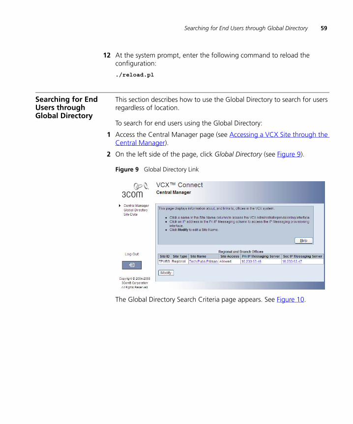
Searching for End Users through Global Directory 59
12 At the system prompt, enter the following command to reload the configuration:
./reload.pl
Searching for End Users through Global Directory
This section describes how to use the Global Directory to search for users regardless of location.
To search for end users using the Global Directory:
1 Access the Central Manager page (see Accessing a VCX Site through the Central Manager).
2 On the left side of the page, click Global Directory (see Figure 9).
Figure 9 Global Directory Link
The Global Directory Search Criteria page appears. See Figure 10.

60 CHAPTER 3: USING THE GLOBAL DIRECTORY
Figure 10 Global Directory Search Criteria Page
3 You can search for end users using five criteria: last name, first name, extension, site ID, or site name. You can use one or more of these criteria to narrow your search results. You can truncate search criteria, and entries are not case-sensitive. For example, you can enter “it” instead of Smith for the last name. All last names containing the sequence “it” are returned.
Enter search criteria using the according to the following field descriptions:
■ Last Name Contains — Enter the entire, or part of, the user’s last name. For example, if you entered smith, Sm, or it any last name containing these characters are returned.
■ First Name Contains — Enter the entire, or part of, the user’s first name. For example, if you entered john or Jo any first name containing these characters are returned.
■ Extension Contains — Enter the entire, or part of, the user’s phone extension such as 1101.
■ Site Id Contains — Enter the unique ID assigned to a region.
■ Site Name Contains – Enter the unique name assigned to a specific site.
4 Click Search.

Locating Global Directory Log Files 61
The search results are listed beneath the Global Directory Search Results heading, see Figure 11.
Figure 11 Global Directory Search Criteria Results
Locating Global Directory Log Files
Any modifications to the global directory using the global directory configuration tool are captured log files that are located in the /opt/3com/VCX/vcxdata/globaldir/log directory.

62 CHAPTER 3: USING THE GLOBAL DIRECTORY
4
CONFIGURING VCX USERSThis chapter provides information on how to add, edit, clone, and delete users through the VCX Administrator web provisioning application. The chapter also provides information on managing the user environment through Class of Service (CoS) and Type of Service (ToS) configuration.
This chapter includes the following topics:
■ Accessing User Configuration Options
■ Managing User Profiles
■ Viewing the Phone Book
Be sure to set your web browser preferences so that the cache is updated whenever you modify or view a new web page.
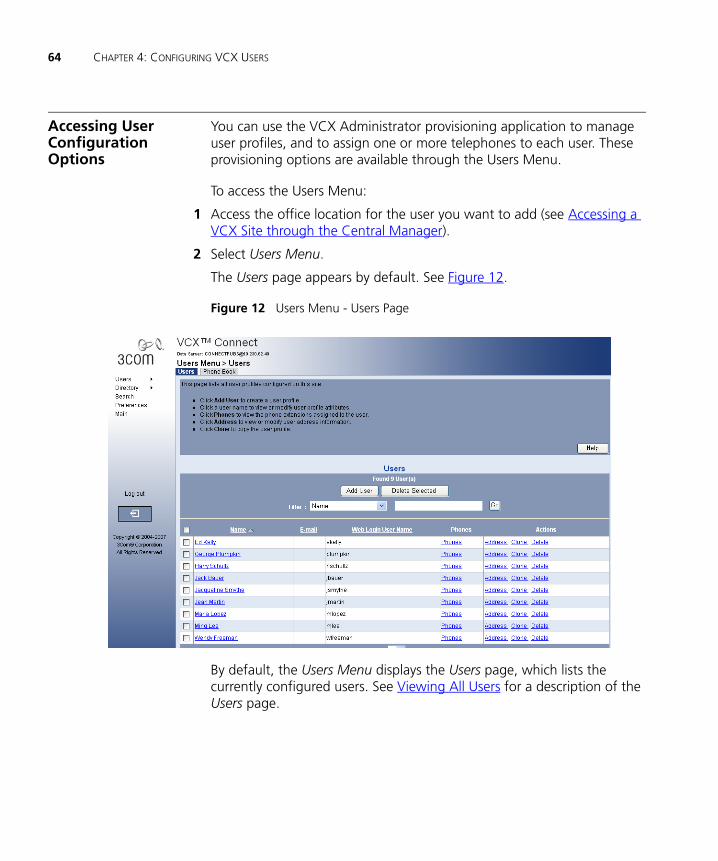
64 CHAPTER 4: CONFIGURING VCX USERS
Accessing User Configuration Options
You can use the VCX Administrator provisioning application to manage user profiles, and to assign one or more telephones to each user. These provisioning options are available through the Users Menu.
To access the Users Menu:
1 Access the office location for the user you want to add (see Accessing a VCX Site through the Central Manager).
2 Select Users Menu.
The Users page appears by default. See Figure 12.
Figure 12 Users Menu - Users Page
By default, the Users Menu displays the Users page, which lists the currently configured users. See Viewing All Users for a description of the Users page.

Accessing User Configuration Options 65
The menu options for the Users Menu appear as submenu options. Selecting a submenu option displays one or more tabbed pages. These pages allow you to:
■ Manage user profiles, configure a Class of Service and configure a Type of Service. These topics are described in this chapter.
■ Manage telephone profiles and extensions, configure an attendant console, and configure emergency services. See Chapter 6.
■ Manage phone features (for example, call forwarding) for a user. See Chapter 9.
■ Manage global phone features (for example, system speed dial numbers). See Chapter 10.
■ Manage calling groups (for example, hunt groups). See Chapter 11.
■ Manage dialing patterns, plans, rules, and number translation. See Chapter 12.
See Using the Graphical User Interface for information on interface options.
Viewing All Users You can use the Users page (Figure 12) to view information for all currently configured users on the server. You can also use this page to edit an existing user profile, delete a user profile, and manage the telephone information for a user.
Each row on the Users page contains six columns of information for each user. Table 8 lists each column and describes the type of information available in that column.
Table 8 Users Page Information
Column Description
Selection box Use the check box to select one or more users. This is useful when the action you want to perform spans multiple users.
Name Specifies the first, middle, and last names of a user.
E-mail Specifies the user’s e-mail address.
User Name Specifies the username used to access the VCX User web interface, and provides a link which allows you to edit the personal information for the user.
Phones Contains a link that allows you to add, view, and modify phone information for the user.

66 CHAPTER 4: CONFIGURING VCX USERS
Managing User Profiles
Every VCX user must have account information configured in a profile. Once configured, the profile can be assigned to one or more telephone extensions. The profile identifies the user and also establishes account information required to access the VCX User application. The user can access this web interface to configure some telephone features (for example, call forwarding) and view account information (for example, calls made and received).
You can use the VCX Administrator provisioning interface to:
■ Create a user profile, which includes the following information:
■ Personal information that identifies the user.
■ Phone features that specify the language and font size used on the user’s telephone LCD Display Panel.
■ Web login information that specifies the username and password required for access to the VCX User web interface.
■ Optionally, you can also enter address information for a user.
■ Modify a user profile,
■ Clone a user profile to save time when creating new user profiles.
■ Delete a user profile,
To manage user profiles:
1 Access the Users page as described in Accessing User Configuration Options.
2 See the online Help for instructions on adding, modifying, cloning, and deleting user profiles.
After adding user profiles, you can assign one or more telephones to each user. See Managing Phone Extensions.
Actions Provides the following three options:
■ Address — Use this option to add or modify address information for a user.
■ Clone — Use this option to clone an existing user profile.
■ Delete — Use this option to delete a user profile.
Table 8 Users Page Information (continued)
Column Description
Viewing the Phone Book 67
Using the UsersSearch Tool
You can search for users based on user information (name or phone extension). You can also search for groups based on group information (see Using the Group Search Tool). In both cases, search results list user information and group membership information.
To search for a user:
1 Select Search Menu.
The User/Groups Search page appears.
2 See the online Help for instructions on entering search criteria to locate one or more users.
Viewing the Phone Book
The Phone Book option lists every user and their associated extension (or extensions) configured on the currently accessed server. This display is for informational purposes and cannot be modified.
An extension is not listed until you assign it to a user. Also, you can prevent the display of an extension in the Phone Book by enabling the Exclude from LCD Directory field on the phone configuration page (see Managing Phone Extensions).
To view all the phones configured on a host server, click Users Menu > Phone Book. Note that a user is not listed until you assign a phone to that user.

68 CHAPTER 4: CONFIGURING VCX USERS
5
CONFIGURING SERVICESThis chapter describes how to configure VCX Classes of Service, Types of Service, and emergency services.
This chapter includes the following topics:
■ Configuring Class of Service
■ Configuring Class of Service Elements
■ Configuring Type of Service
■ Configuring Emergency Services

70 CHAPTER 5: CONFIGURING SERVICES
Configuring Class of Service
When you create a phone extension, you assign the extension to a phone profile (see Managing Phone Extensions). A phone profile includes a set of common phone attributes, including a Class of Service (CoS). A CoS determines the incoming and outgoing phone numbers a phone is allowed to dial or receive.
Each Class of Service includes one or more elements. Each element includes one or more dialing patterns. A pattern identifies a dial string prefix. For example, your VCX system could include the following:
A Class of Service named Sample Class of Service, which includes:
A CoS element named Toll, which includes:
Two patterns:
91900*
91976*
A CoS element can be configured to allow (whitelist) or block (blacklist) an inbound or outbound call whose dial string matches the element’s pattern (or patterns). So, for example, if you configured the Toll element to block outbound calls, any phone assigned to the Sample Class of Service could not complete a call to a number whose dial string included the prefix 91900 or 91976.
For each Class of Service, you can also configure Trunk to Trunk Transfer and Forward to Trunk dialing.
■ Trunk to Trunk Transfer — If enabled, users are allowed to transfer a call from outside the phone system (from a PSTN) to somewhere else outside the internal phone system. For example, if phone A (located on the PSTN) calls phone B (located on the VCX system), phone B can forward the call to phone C (located on the PSTN). This creates a “bridge” between phone A and phone C and the company of phone B pays for the call.
■ Forward to Trunk — If enabled, users are allowed to forward calls to the PSTN. For example, a user could configure his or her phone to forward calls to an international location. Consequently, the user’s company pays for the long distance call and not the user.

Configuring Class of Service 71
Your VCX system includes several preconfigured Classes of Service. You can modify an existing CoS or create a new one. In addition, you can create CoS elements and add them to an existing CoS, or you can modify existing CoS elements.
Note the following additional CoS considerations:
■ Emergency calls (such as calls to 911) are not subject to CoS restrictions and cannot be blacklisted. Emergency numbers are configured and controlled through the Emergency Services menu option (see Configuring Emergency Services).
■ System-wide Speed Dial numbers are subject to Class of Service restrictions. For example, if a phone is assigned to a CoS that prohibits dialing toll-free numbers, a System Speed Dial configured for a specific toll number will not work on that phone.
■ When you create a new phone profile (see Managing Phone Extensions), the system assigns the default CoS unless you specify a different one. If you edit the properties of the default CoS, verify that it contains a minimum set of permissions.
You can use the VCX Administrator provisioning interface to:
■ Add a CoS.
■ Modify a CoS to change the following:
■ The elements assigned to the CoS
■ How elements are applied to inbound and outbound calls (the whitelist or blacklist status)
■ The Trunk to Trunk Transfer and Forward to Trunk status applied to calls
■ Delete a CoS.
■ Add or delete a CoS element. See Configuring Class of Service Elements.
To manage a Class of Service:
1 Select Users Menu > Services > Class of Service.
The Class of Services page appears.
2 See the online Help for instructions on managing a Class of Service.

72 CHAPTER 5: CONFIGURING SERVICES
Configuring Class ofService Elements
Class of Service elements include one or more dialing patterns. Patterns are typically grouped in an element according to type. For example, the CoS element TollFree could contain patterns (91800*, 91888*) that identify long distance calls that are paid by the called party. When you create an element, it is available to any Class of Service. A CoS element can be assigned to multiple Classes of Service.
To manage Class of Service elements:
1 Select Users Menu > Services > CoS Elements.
The Elements page appears listing all the currently configured Class of Service elements.
2 See the online Help for instructions on adding or deleting a Class of Service.
Configuring Type of Service
When you create a phone extension, you assign the extension to a phone profile (see Managing Phone Extensions). A phone profile includes a set of common phone attributes, including a Type of Service (ToS). A Type of Service (ToS) determines what phone features are available to an extension.
A ToS is comprised of a set of phone features. For example, these features can include options that allow configuration of call forwarding or personal speed dialing. A ToS allows you to bundle common phone features into one Type of Service and assign that ToS to a phone profile. This allows you to assign default phone features for a range of extensions.
Some features, such as Do Not Disturb, are available in every ToS and cannot be removed. Other features, such as Silent Monitor and Barge In, can be included or excluded from ToS.
For example, Figure 13 shows the configuration page for the No SM-BI ToS, which is included with VCX software. Notice that the Silent Monitor and Barge In feature is not listed in the Provisioned Feature column.
An excluded feature cannot be mapped to a telephone button or invoked through the Telephone User Interface on a phone.
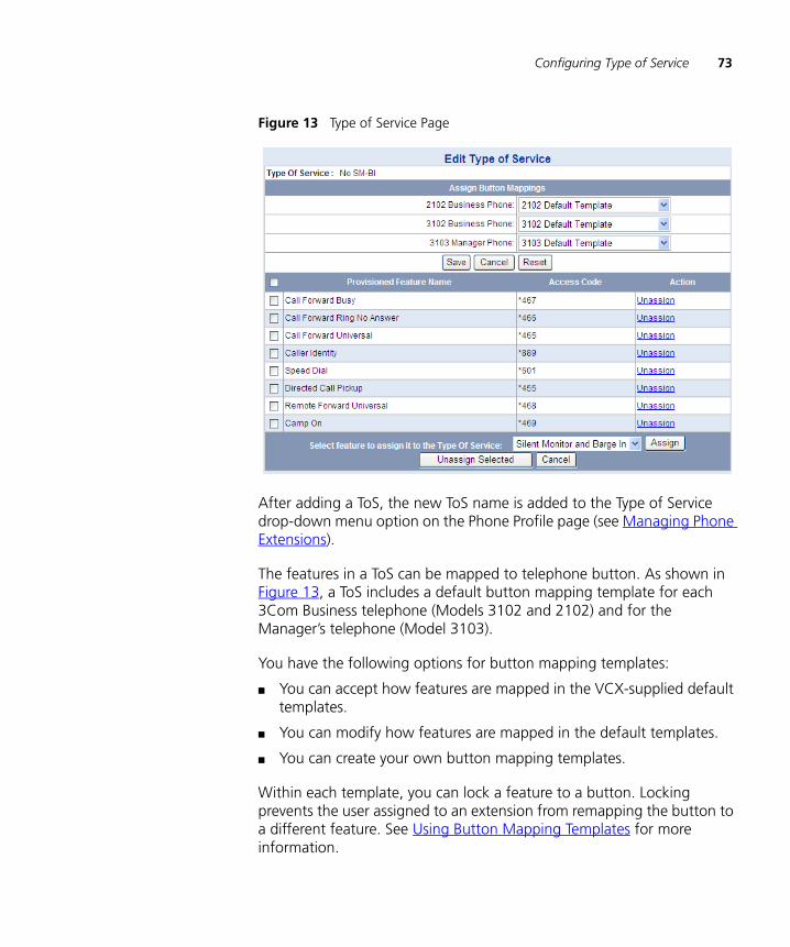
Configuring Type of Service 73
Figure 13 Type of Service Page
After adding a ToS, the new ToS name is added to the Type of Service drop-down menu option on the Phone Profile page (see Managing Phone Extensions).
The features in a ToS can be mapped to telephone button. As shown in Figure 13, a ToS includes a default button mapping template for each 3Com Business telephone (Models 3102 and 2102) and for the Manager’s telephone (Model 3103).
You have the following options for button mapping templates:
■ You can accept how features are mapped in the VCX-supplied default templates.
■ You can modify how features are mapped in the default templates.
■ You can create your own button mapping templates.
Within each template, you can lock a feature to a button. Locking prevents the user assigned to an extension from remapping the button to a different feature. See Using Button Mapping Templates for more information.
74 CHAPTER 5: CONFIGURING SERVICES
After selecting the button mapping template to use for each phone model, you assign the templates to a ToS, create a phone profile that includes the ToS, and assign phone extensions to use the profile.
You can use the VCX Administrator provisioning interface to:
■ Add a ToS.
■ Modify a ToS.
■ Delete a ToS.
To manage a Type of Service:
1 Select Users Menu > Services > Type of Service.
The Type of Service page appears.
2 See the online Help for instructions on managing a ToS.
Once a ToS is assigned to a phone profile, it is important to understand the consequences for phone extensions that use that profile (and ToS). Initially, all phones assigned to a phone profile use the button mapping specified in the button mapping template appropriate for the phone model. However, for each phone model, the number of features you can map exceeds the number of buttons on the phone. Note the following considerations:
■ You can remap the feature assigned to a button for a particular extension. For example, the button mapping template in effect may include the Silent Monitor and Barge In feature but not map it to a button. If you want the extension assigned to a supervisor to use the Silent Monitor feature, you can modify the button mapping for that extension through the VCX Administrator provisioning interface (see Configuring Features Mapped to Telephone Buttons).
■ Unless you lock a feature to a button, a user can remap the feature assigned to a button. Unlocked features can be configured by the user through the VCX User interface or the Telephone User Interface (TUI).
Once a ToS is assigned to a phone profile, it is also important to understand the consequences of modifying the ToS or assigning a new ToS to a profile.
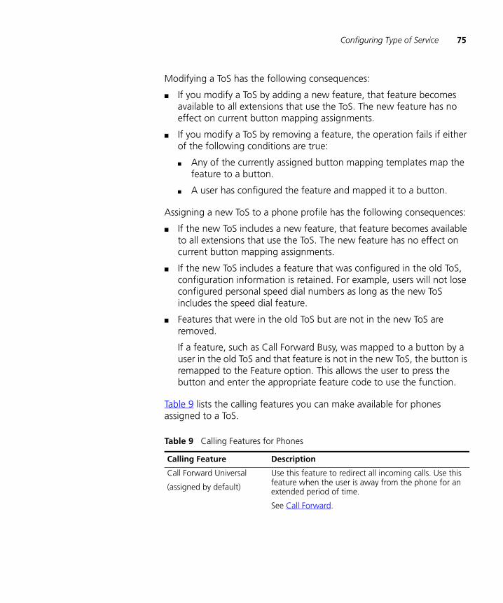
Configuring Type of Service 75
Modifying a ToS has the following consequences:
■ If you modify a ToS by adding a new feature, that feature becomes available to all extensions that use the ToS. The new feature has no effect on current button mapping assignments.
■ If you modify a ToS by removing a feature, the operation fails if either of the following conditions are true:
■ Any of the currently assigned button mapping templates map the feature to a button.
■ A user has configured the feature and mapped it to a button.
Assigning a new ToS to a phone profile has the following consequences:
■ If the new ToS includes a new feature, that feature becomes available to all extensions that use the ToS. The new feature has no effect on current button mapping assignments.
■ If the new ToS includes a feature that was configured in the old ToS, configuration information is retained. For example, users will not lose configured personal speed dial numbers as long as the new ToS includes the speed dial feature.
■ Features that were in the old ToS but are not in the new ToS are removed.
If a feature, such as Call Forward Busy, was mapped to a button by a user in the old ToS and that feature is not in the new ToS, the button is remapped to the Feature option. This allows the user to press the button and enter the appropriate feature code to use the function.
Table 9 lists the calling features you can make available for phones assigned to a ToS.
Table 9 Calling Features for Phones
Calling Feature Description
Call Forward Universal
(assigned by default)
Use this feature to redirect all incoming calls. Use this feature when the user is away from the phone for an extended period of time.
See Call Forward.

76 CHAPTER 5: CONFIGURING SERVICES
Speed Dial
(assigned by default)
When making a call, use a speed dial to provide short-cut dial strings for frequently used phone numbers.
These speed dials are phone specific, not system-wide.
See Configuring Personal Speed Dial Numbers.
Call Forward Busy Use this feature to redirect incoming calls when this phone is busy. If the user has multiple lines on this phone, the busy is defined as all lines exhausted with existing calls.
See Call Forward.
Call Forward Ring No Answer
Use this feature to redirect incoming calls when this phone rings for a specific time period (in seconds).
See Call Forward.
Caller Identity This feature blocks caller identity information (user name and phone extension) from appearing on called party’s LCD Display Panel.
This feature can be enabled for all calls or for the next call only.
The block caller ID for the next call feature overrides the current setting for block caller ID for all calls.
See Caller Identity.
Directed Call Pickup By enabling this feature and creating a security code, a user can answer their own telephone from another desk. To answer the call a person uses an access code from any telephone within the network domain, enters their security code (user defines), and then enters the extension number of the ringing phone. This transfers the call to the telephone they are on.
The default security code is *52.
See Directed Call Pickup.
Remote Forward Universal By enabling this feature, you give a user the ability to forward someone else’s calls to any other extension, including their own within the network.
When enabled, the remote (destination) phone’s LED (if available) flashes for all forwarded calls, and the LCD displays a call forward message.
This enables or disables the Call Forward Universal feature on the source phone.
See Remote Forward Universal.
Table 9 Calling Features for Phones (continued)
Calling Feature Description
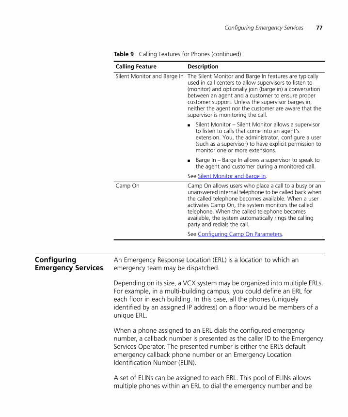
Configuring Emergency Services 77
Configuring Emergency Services
An Emergency Response Location (ERL) is a location to which an emergency team may be dispatched.
Depending on its size, a VCX system may be organized into multiple ERLs. For example, in a multi-building campus, you could define an ERL for each floor in each building. In this case, all the phones (uniquely identified by an assigned IP address) on a floor would be members of a unique ERL.
When a phone assigned to an ERL dials the configured emergency number, a callback number is presented as the caller ID to the Emergency Services Operator. The presented number is either the ERL’s default emergency callback phone number or an Emergency Location Identification Number (ELIN).
A set of ELINs can be assigned to each ERL. This pool of ELINs allows multiple phones within an ERL to dial the emergency number and be
Silent Monitor and Barge In The Silent Monitor and Barge In features are typically used in call centers to allow supervisors to listen to (monitor) and optionally join (barge in) a conversation between an agent and a customer to ensure proper customer support. Unless the supervisor barges in, neither the agent nor the customer are aware that the supervisor is monitoring the call.
■ Silent Monitor – Silent Monitor allows a supervisor to listen to calls that come into an agent’s extension. You, the administrator, configure a user (such as a supervisor) to have explicit permission to monitor one or more extensions.
■ Barge In – Barge In allows a supervisor to speak to the agent and customer during a monitored call.
See Silent Monitor and Barge In.
Camp On Camp On allows users who place a call to a busy or an unanswered internal telephone to be called back when the called telephone becomes available. When a user activates Camp On, the system monitors the called telephone. When the called telephone becomes available, the system automatically rings the calling party and redials the call.
See Configuring Camp On Parameters.
Table 9 Calling Features for Phones (continued)
Calling Feature Description
78 CHAPTER 5: CONFIGURING SERVICES
assigned a unique callback number (an ELIN). When a caller dials the emergency number, an ELIN is associated with the IP address of the phone. The Emergency Services Operator can use the ELIN to call back the emergency caller.
Normally, an ELIN remains in use (cannot be assigned to a new caller) unless the Emergency Services Operator hangs up before the emergency caller hangs up. However, if the ELIN is not released in this manner, the usage release timer specifies how long the ELIN remains unavailable for reassignment. A second timer, the association release timer, specifies how long an ELIN is associated with the IP address of the calling phone. This allows an ELIN to be associated with a phone after the usage timer expires. However, if a new emergency call comes in, the ELIN can be assigned to the new caller and the old ELIN-phone association is overwritten.
If all the ELINs associated with an ERL are in use, the default ERL emergency callback number is used instead.
Additionally, you can specify a set of emergency gateways, which are used to directly reach the emergency service if the call processor is unavailable.
To ensure that emergency calls always go through, a set of system-wide defaults are defined — the callback phone number and an emergency gateway, identified by its IP address. These system defaults are used, for example, if a phone is not associated with any ELIN or if the call processor is down.
The emergency dialable digits are controlled by the ERL screens. If the emergency digits are identified by an ERL then those emergency dialable digits will not be applied a Class of Service treatment. Just because a Class of Service Element is named Emergency and is blacklisted does not mean that Emergency calls will not go through.
Note that a VCX phone can dial an emergency phone number even if the phone is not logged in to the VCX system. However, the phone must be properly configured with the IP address of the VCX call processor, have a network connection to an operational VCX system, and the region must support emergency dialing. If the VCX system is not operational, an emergency call can be routed (optionally) directly through a PSTN media gateway. Also note that an emergency call cannot be put on hold.

Configuring Emergency Services 79
CAUTION: You must ensure that a dial plan and dial pattern exist for your emergency number, and that the dial plan is included in the phone profile assigned to your users’ extensions. VCX software provides, by default, a dial plan named Emergency that includes the emergency numbers 911 and 9911. See Chapter 12 for information on patterns, dial plans, and dial rules.
Emergency CallingConsiderations for
Roaming Users
As described in User Roaming Services, VCX software version 7.1 allows a user to log in to any phone in the system, regardless of the call processor to which the phone is connected. The user simply configures the phone with his or her extension and logs in with the appropriate password. This allows, for example, a user whose phone extension is configured at a branch office, to assign that extension to a phone at regional office. Consequently, the user’s branch extension and phone features are enabled on the phone at the regional office.
A VCX Connect system provides telephony services for users in a single site. Roaming services, therefore, are not required in a VCX Connect system.
The processor on which the phone extension is configured is referred to as the home call processor. The processor to which the phone is connected is referred to as the foreign call processor.
Although the phone has been assigned an extension configured on the remote home processor (a branch office, for example), the phone retains the IP address that was assigned when the phone booted at the foreign call processor (a regional office, for example). An ELIN (see the previous section) is associated with a range of phone IP addresses.
Note the following implications for emergency calls made by a roaming user:
■ If a roaming user makes an emergency call using a dialing pattern that matches an emergency number configured for the foreign site, the foreign call processor intercepts the call and routes it locally.
■ If a roaming user makes an emergency call using the dialing pattern for his or her home site, and that pattern does not match the pattern configured on the foreign call processor, the emergency call is routed using the home site configuration. As a result, the user may be sent to an emergency response center that cannot support the location that originated the call.
80 CHAPTER 5: CONFIGURING SERVICES
■ For enhanced emergency services to work for all roaming situations, the home site (for example, a branch office) and its backup site (for example, the regional office to which the branch is connected) must have IP address range-based ERLs defined for the phones at each site. In this case, VCX software will use the a phone’s assigned IP address to determine if an ERL from the home location or the ERL from the backup location should be used. This covers both of the following cases:
■ A branch phone makes an emergency call when the phone has roamed to its regional call processor. This enables the emergency call to go to regional emergency center.
■ A branch phone makes an emergency call when the phone has failed over to its regional (backup) call processor. This enables the emergency call to go to branch emergency center.
Managing ERLs The Emergency Services page enables you to add, modify, or delete Emergency Response Locations (ERLs).
Once you have added an ERL, you can set up other emergency parameters (such as the Emergency Location Identification Number) to complete the ERL configuration.
To add or modify an ERL:
1 Select Users Menu > Services > Emergency.
The Emergency Defaults and Emergency Services page appears.

Configuring Emergency Services 81
Figure 14 Emergency Defaults and Emergency Services Page
2 Select one of the following options:
■ To add an ERL, click Add ERL.
■ To modify an existing ERL, click name of the ERL in the ERL column.
The Add Emergency Location page or Edit Emergency Location page appears.
3 In the Location field, enter the ERL location based on geographic or physical location. For example, Bldg1-Flr1. There is a 10 character limit.
4 In the Emergency Callback Phone field, enter the phone number of the contact person responsible for emergency situations within an organization (for example, a security guard).
5 Click Save.
The ERL is added to the Emergency Services heading.

82 CHAPTER 5: CONFIGURING SERVICES
Figure 15 Emergency Defaults and Emergency Response Locations Window
Deleting ERLs To delete an ERL:
1 Select Users Menu > Services > Emergency.
The Emergency Defaults and Emergency Services page appears.
2 Enter a check mark in the check box preceding the ERL you want to delete.
3 Click Delete Selected.
A pop-up window appears prompting you to confirm the ERL delete action.
4 Click OK.
The Emergency Defaults and Emergency Services page refreshes.
Managing IP AddressRanges for an ERL
The Emergency Services page enables you to add, modify, or delete the IP address range associated with an Emergency Response Location (ERL).
The range specifies the telephones that can be included within this ERL (for example, all telephones on the 1st floor of a building). Each phone in an ERL is assigned an IP address from a range of IP addressed specified by a network address and subnet mask.
Configuring Emergency Services 83
CAUTION: If Emergency service settings or emergency lines are changed, (for example, the gateway IP address or emergency digits) they will not take effect until the telephones are power cycled. A simple logout/login of the telephone is not adequate.
To add or modify the IP address range for an ERL:
1 Select Users Menu > Services > Emergency Services.
The Emergency Defaults and Emergency Services page appears.
2 Click IP Ranges for the appropriate ERL.
The IP Ranges page appears.
3 Select one of the following options:
■ To add an IP address range, click Add IP Range.
■ To modify an existing range, click the IP address in the Network IP column.
The Add IP Range page or Edit IP Range page appears.
4 In the IP Address field, enter the IP network address that identifies the range addresses you want to include in this ERL.
5 In the Subnet Mask field, enter the subnet mask for this IP address range.
6 Click Save.
The IP Ranges page refreshes showing the new IP address range.
Deleting IP Addresses from an ERL
To delete an IP address range from an ERL.
1 Select Users Menu > Services > Emergency.
The Emergency Defaults and Emergency Services page appears.
2 In the Location Settings column, click IP Ranges for the ERL you want to edit.
The IP Ranges page appears.
3 Enter a check mark in the check box preceding the IP address you want to delete.
4 Click Delete Selected.
A pop-up window appears prompting you to confirm the IP address delete action.
5 Click OK.

84 CHAPTER 5: CONFIGURING SERVICES
The IP Ranges page refreshes verifying the IP address(es) were deleted.
Managing EmergencyNumbers for an ERL
The Emergency Services page enables you to add, modify, or delete the emergency numbers associated with an Emergency Response Location (ERL).
Dialing an emergency number signals the gateway that the call is an emergency and should be handled differently in case of a disconnect.
CAUTION: If Emergency service settings or emergency lines are changed, (for example, the gateway IP address or emergency digits) they will not take effect until the telephones are power cycled. A simple logout/login of the telephone is not adequate.
To add or modify an emergency number for an ERL:
1 Select Users Menu > Services > Emergency Services.
The Emergency Defaults and Emergency Services page appears.
2 Click Emergency Numbers.
The Emergency Numbers page appears.
3 Select one of the following options:
■ To add an emergency number, click Add Emergency Number.
■ To modify an existing emergency number, click the number in the Emergency Number column.
The Add Emergency Number page or Edit Emergency Number page appears.
4 In the Emergency Number field, enter an emergency number that will signal the gateway to treat it as an emergency number when dialed (for example, 911.
You cannot configure an emergency number that conflicts with any of the following existing extensions:
■ User extensions in either local or global directory
■ Voicemail or Music on Hold numbers
■ Extensions associated with a hunt group
■ Extensions within a call park range
■ Extensions configured for emergency services
■ Extensions configured for call coverage

Configuring Emergency Services 85
■ Extensions configured for call forwarding
5 Click Save.
6 The Emergency Numbers page refreshes showing the new emergency number.
Deleting Emergency Numbers from an ERL
To delete an Emergency Number from an ERL.
1 Select Users Menu > Services > Emergency.
The Emergency Defaults and Emergency Services page appears.
2 From the Location Settings column, click Emergency Numbers for the ERL you want to configure.
The Emergency Numbers page appears.
3 Enter a check mark in the check box preceding the emergency number you want to delete.
4 Click Delete Selected.
A pop-up window appears prompting you to confirm the emergency number delete action.
5 Click OK.
The Emergency Numbers page refreshes verifying that the emergency number was deleted.
Managing EmergencyGateways for an ERL
The Emergency Gateway IP Addresses page enables you to add, modify, or delete the IP address of the gateway used to reach an emergency service provider if the call processor is unavailable.
You can add multiple gateways to create a redundant configuration.
CAUTION: If Emergency service settings or emergency lines are changed, (for example, the gateway IP address or emergency digits) they will not take effect until the telephones are power cycled. A simple logout/login of the telephone is not adequate.
To add or edit an Emergency Gateway IP Address for an ERL.
1 Select Users Menu > Services > Emergency Services.
The Emergency Defaults and Emergency Services page appears.
86 CHAPTER 5: CONFIGURING SERVICES
2 From the Location Settings column, click Emergency Gateway IP for the ERL you want to configure.
The Emergency Gateway IP Addresses page appears.
3 Select one of the following options:
■ To add an emergency gateway IP address, click Add Gateway IP.
■ To modify an existing emergency gateway IP address, click the address in the IP Address column.
The Add Gateway IP page or Edit Gateway IP page appears.
4 In the Gateway IP Address field, enter the IP address of the gateway to which you want emergency calls routed for the telephones within the ERL.
5 Click Save.
The Emergency Gateway IP Addresses page refreshes showing the emergency gateway.
Deleting Emergency Gateway IP Addresses from an ERL
To delete an Emergency Gateway IP Address from an ERL.
1 Select Users Menu > Services > Emergency.
The Emergency Defaults and Emergency Services page appears.
2 From the Location Settings column, click Emergency Gateway IP for the ERL you want to configure.
The Emergency Gateway IP Addresses page appears.
3 Enter a check mark in the check box preceding the emergency gateway IP address you want to delete.
4 Click Delete Selected.
A pop-up window appears prompting you to confirm the emergency gateway IP address delete action.
5 Click OK.
The Emergency Gateway IP Addresses page refreshes verifying the emergency gateway IP was deleted.
Managing EmergencyLines for an ERL
The Emergency Line ID Numbers page enables you to add, modify, or delete Emergency Location Identification Numbers (ELINs). You can configure multiple ELINs for each ERL.
Configuring Emergency Services 87
When a phone assigned to an ERL dials the configured emergency number, a callback number is presented as the caller ID to the Emergency Services Operator. The presented number is either the ERL’s default emergency callback phone number or an Emergency Location Identification Number (ELIN).
CAUTION: If Emergency service settings or emergency lines are changed, (for example, the gateway IP address or emergency digits) they will not take effect until the telephones are power cycled. A simple logout/login of the telephone is not adequate enough.
CAUTION: Ensure that the emergency line you want to modify is not in use, The Usage State field on the Emergency Line ID Numbers page must be Not in use.
To add or edit an ELIN for an ERL.
1 Select Users Menu > Services > Emergency Services.
The Emergency Defaults and Emergency Services page appears.
2 From the Location Settings column, click Emergency Lines for the ERL you want to configure.
The Emergency Line ID Numbers page appears.
3 Select one of the following options:
■ To add an ELIN, click Add ELIN.
■ To modify an existing ELIN, click the number in the ELIN column.
The Add Emergency Line ID Number page or Edit Emergency Line ID Number page appears.
4 Click Add ELIN.
5 The Add Emergency Line ID Number page appears.
6 In the ELIN field, enter the Emergency Location Identification Number. An ELIN is a fully qualified E.164 number.
You cannot configure an ELIN that conflicts with any of the following existing extensions:
■ User extensions in either local or global directory
■ Voicemail or Music on Hold numbers
■ Extensions associated with a hunt group
■ Extensions within a call park range

88 CHAPTER 5: CONFIGURING SERVICES
■ Extensions configured for emergency services
■ Extensions configured for call coverage
■ Extensions configured for call forwarding
7 In the Association Release Timer field, enter the amount of time you want to leave the ELIN associated with the emergency caller. The number is specified in hours and the range is 1 through 24. This association is used to callback the emergency caller. After the configured time expires, the association between the emergency caller and ELIN is dropped. In case an ELIN is not in use, it can be assigned to a new emergency caller and the association with an older emergency caller is overwritten with the association of the new emergency caller.
8 In the Usage Release Timer field, enter in the maximum amount of time you want to allow the ELIN to remain in use. The number is specified in hours and the range is 1 through 24. Normally, an ELIN is freed when the emergency service provider goes on-hook before the emergency caller goes on-hook, otherwise, the ELIN is kept in use for the duration of this timer.
9 Click Save.
The Emergency Line ID Numbers page refreshes, showing the ELIN.
Deleting Emergency Lines from an ERL
To delete an Emergency Line from an ERL.
1 Select Users Menu > Services > Emergency.
The Emergency Defaults and Emergency Services page appears.
2 From the Location Settings column, click Emergency Lines for the ERL you want to configure.
The Emergency Line ID Numbers page appears.
3 Enter a check mark in the check box preceding the ELIN you want to delete.
4 Click Delete Selected.
A pop-up window appears prompting you to confirm the ELIN delete action.
5 Click OK.
The Emergency Line ID Numbers page refreshes verifying the ELIN was deleted.

Configuring Emergency Services 89
Adding or Editing theEmergency Defaults
The emergency defaults are used when there is no information in the emergency response database for a emergency caller (phone IP address). Typically, phone IP addresses are stored within ranges for a defined ERL.
CAUTION: If Emergency service settings or emergency lines are changed, (for example, the gateway IP address or emergency numbers) they will not take effect until the telephones are power cycled. A simple logout/login of the telephone is not sufficient.
To add or edit the emergency defaults:
1 Select Users Menu > Services > Emergency.
The Emergency Defaults and Emergency Services page appears.
2 In the Gateway IP Address field, enter the IP address of a system-wide emergency gateway.
3 In the Emergency Callback Phone field, enter the phone number of the contact person responsible for emergency situations within the organization (for example, a security guard).
4 Click Save.
The Emergency Default is applied to the entire organization.

90 CHAPTER 5: CONFIGURING SERVICES

6
MANAGING VCX PHONE PROFILES AND EXTENSIONSThis chapter describes how to manage telephone profiles and extensions. It also describes how to assign an extension to a user and how to configure an attendant console.
This chapter includes the following topics:
■ Accessing Phone Configuration Options
■ Managing Phone Profiles
■ Managing Phone Extensions
■ Assigning a Phone Extension to a User
■ Deleting a Phone Extension
■ Viewing Phone Registration Information
■ Viewing Call History
■ Configuring Media Access Control
■ Configuring an Attendant Console
Be sure to set your web browser preferences so that the cache is updated whenever you modify or view a new web page.

92 CHAPTER 6: MANAGING VCX PHONE PROFILES AND EXTENSIONS
Accessing Phone Configuration Options
You can use the VCX Administrator provisioning application to manage telephone profiles and extensions, configure an attendant console, and phone management options. Pages for these tasks are available through phone configuration options available on the Users Menu.
To access phone configuration pages:
1 Access the office location you want to manage (see Accessing a VCX Site through the Central Manager).
2 Select Users Menu > Phones.
The Phones page appears. See Figure 16.
Figure 16 Users Menu > Phones > Phones Page
This page lists all the phone extensions configured on the selected VCX server.
You can use this page to perform the following tasks:
■ Add one or more phone extensions. Click Add Phone and see Adding Phone Extensions.
■ Modify phone extension settings. Click a phone extension in the Phone Address column and see Modifying a Phone Extension.
■ View and modify the phone profile settings. Click a profile name in the Phone Profile column and see Editing a Phone Profile.
■ View and modify user information. Click a name in the User Name column and see Managing User Profiles.

Managing Phone Profiles 93
■ Modify the MAC address or lock status associated with the phone extension (if assigned). Click an address in the MAC column and see Configuring Media Access Control.
■ View phone registration information, such as the IP address assigned to the phone. Click Registrations in the Actions column and see Viewing Phone Registration Information.
■ View the call history for a phone. Click Call History and see Viewing Call History.
■ View the hunt group (or groups) to which an extension is assigned. Click Hunt Groups and see Configuring Hunt Groups and Attendants.
■ Display a list of users available for assignment to an unassigned extension. Click Users and see Assigning a Phone Extension to a User. Note that the Users option only appears in the Actions column for unassigned extensions (see Figure 16).
■ Override phone settings (such as date and time format, and ring tones) configured by a user through the VCX User web interface. Click Settings and see Modifying a User’s Phone Settings.
■ Delete one or more phone extensions. See Deleting a Phone Extension.
The other options in the Actions column (Features, Call Coverage, Button Mappings, Call Restrictions, Selective Ringing, Bridge Permissions, and Bridged Phones) are described in Chapter 9.
For information on user interface components, see Using the Graphical User Interface.
Managing Phone Profiles
Each phone extension has an associated phone profile. A phone profile includes a set of attributes (for example, a dial plan and Class of Service) that are common to all phones that use the profile.
This section describes how to create, modify, clone, and delete a phone profile. It also describes how to list the phones associated with a profile.
If you have a VCX Connect system, the installer has the option of importing telephony data, including one or more phone profiles. See the following section, VCX Connect Sample Phone Profiles.

94 CHAPTER 6: MANAGING VCX PHONE PROFILES AND EXTENSIONS
VCX Connect SamplePhone Profiles
Unlike enterprise VCX systems, a VCX Connect system can be pre-configured with telephony data.
Whether or not a VCX Connect system is preconfigured depends on how the VCX software is installed.
■ If the VCX Connect installation is performed through the command line, telephony data cannot be preconfigured. The VCX Connect system must be completely configured through the VCX Administrator provisioning application.
■ If the VCX Connect installation is performed through the First Time Configuration web interface, the installer has two options:
■ Use a customized import file to preconfigure the system. In this case, the level of configuration depends on the content of the import file.
■ Use the sample telephony data supplied by 3Com Corporation to preconfigure the system. This sample data includes the six phone profiles described in Table 10.
All the phone profiles in Table 10 use the 4-NANP dial plan (see Configuring Dial Plans).
Table 10 VCX Connect System Sample Phone Profiles
Phone Profile Name Description
Standard Includes voicemail; allows long-distance calling; prohibits Call Forward Universal.
No-Voicemail Same as Standard but without voicemail. Useful for conference room phones or users who do not require voicemail.
No-Longdistance Same as Standard, but without long-distance calling. Useful for employees restricted to local calling only.
No-Longdistance-No-Voicemail Excludes both long-distance calling and voicemail. Useful for common area or in-house phones.
Fax-Modem Optimized for fax or modem use. No voicemail.
Executive Same as Standard, but with Call Forward Universal permitted.
Managing Phone Profiles 95
Creating a PhoneProfile
You can create multiple phone profiles customized for different groups of phone users. For example, you can create a different phone profile for sales, accounting, and customer service.
A phone profile specifies a primary and secondary call processor, and an associated range of telephone extensions.
In a multi-site VCX environment that includes branch offices, you can create a phone profile for each branch. The branch phone profile specifies the branch’s primary, secondary call processor, and an associated range of telephone extensions.
A VCX Connect system provides telephony services for users in a single site. You can, however, use the Global Directory to link multiple VCX Connect sites.
One profile, with general settings, is typically designated as the default phone profile. All phone extensions must be associated with a phone profile.
VCX software can synchronize some phone profile data configured on a VCX IP Telephony server (for example, voicemail extension and user account information) by exporting the data to an IP Messaging server. See About IP Telephony and IP Messaging Data Synchronization for more information.
To create a phone profile:
1 Select Users Menu > Phones > Phone Profiles.
The Phone Profiles page appears listing all current profiles.
2 Click Add Phone Profile.
The Add Phone Profile page appears.
3 See the online Help for instructions on adding phone profiles.
After creating a profile, you can add phones to your VCX system and assign them to the phone profile (see Managing Phone Extensions).
Note that you can override some phone profile field values for an individual extension on the User Phone Settings page. For example, you may want to configure a ring tone for a particular extension. See Modifying a User’s Phone Settings for more information.
96 CHAPTER 6: MANAGING VCX PHONE PROFILES AND EXTENSIONS
Editing a PhoneProfile
You can modify the settings in an active phone profile. This allows you to correct profile errors or update settings for a group of phones in one step.
When you change a phone profile, all profile settings (not just the changed settings) are reset on all phones associated with that profile. If a user has changed one or more personal settings (for example, ring tones), the reapplied profile overrides any personal settings. If this is a concern, you should warn users that their personal phone settings may be affected by the profile change. Modifying a phone profile also overrides settings configured for individual extensions on the User Phone Settings page. See Modifying a User’s Phone Settings for more information.
To edit a phone profile:
1 Select Users Menu > Phones > Phone Profiles.
The Phone Profiles page appears listing all current profiles.
2 Click the name of the phone profile you want to modify.
The Edit Phone Profile page appears.
3 See the online Help for instructions on modifying a phone profile.
Viewing PhoneProfile Member
Phones
You can view all the phones assigned to a phone profile.
To view phone profile member phones:
1 Select Users Menu > Phones > Phone Profiles.
The Phone Profiles page appears listing all current profiles.
2 Click Members in the Actions column for a phone profile.
The Phone Profile Members page appears. See Figure 17.
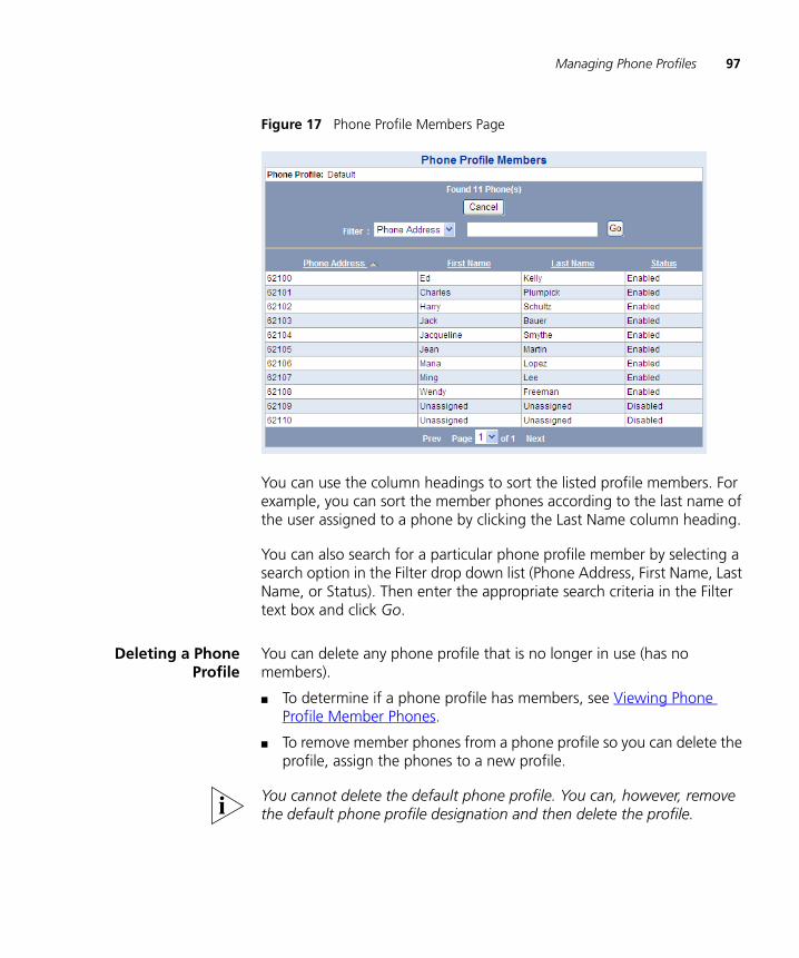
Managing Phone Profiles 97
Figure 17 Phone Profile Members Page
You can use the column headings to sort the listed profile members. For example, you can sort the member phones according to the last name of the user assigned to a phone by clicking the Last Name column heading.
You can also search for a particular phone profile member by selecting a search option in the Filter drop down list (Phone Address, First Name, Last Name, or Status). Then enter the appropriate search criteria in the Filter text box and click Go.
Deleting a PhoneProfile
You can delete any phone profile that is no longer in use (has no members).
■ To determine if a phone profile has members, see Viewing Phone Profile Member Phones.
■ To remove member phones from a phone profile so you can delete the profile, assign the phones to a new profile.
You cannot delete the default phone profile. You can, however, remove the default phone profile designation and then delete the profile.

98 CHAPTER 6: MANAGING VCX PHONE PROFILES AND EXTENSIONS
To delete one or more phone profiles:
1 Select Users Menu > Phones > Phone Profiles.
The Phone Profiles page appears listing all current profiles.
2 See the online Help for instructions on deleting phone profiles.
Cloning a PhoneProfile
You can clone an existing phone profile to save time when creating new profiles. The cloning option generates an Add Profile page that duplicates the settings in an existing profile but allows you to modify any field value before saving. This feature is particularly useful when you want to create a new phone profile that uses most of the settings already configured in an existing profile.
To clone a phone profile:
1 Select Users Menu > Phones > Phone Profiles.
The Phone Profiles page appears listing all current profiles.
2 Click Clone in the Actions column for the phone profile you want to duplicate.
3 See the online Help for instructions on cloning phone profiles.
Managing Phone Extensions
You can create a single phone extension or you can create a range of extensions. You can also modify phone extensions settings (for example, the profile assigned to a phone) and delete phone extensions. Phone extension management tasks are executed on the Phones page. This page is described in Accessing Phone Configuration Options.
VCX software requires a license key to prevent unauthorized use of the product. Keys are embedded in license key files. A license key specifies:
■ The type and number of telephones a VCX system will support.
■ The number of voice mailboxes the system supports.
Each server in a VCX system that processes calls or voicemail messages requires installation of a unique license key file. See the VCX Maintenance Guide for licensing information.
Managing Phone Extensions 99
Adding PhoneExtensions
This section describes how to add one or more phone extensions to your VCX system.
While you can run the VCX Administrator provisioning application on a branch site to add new telephone extensions, 3Com Corporation strongly recommends that you add all extensions on the regional site. This practice prevents duplication of extension numbers and avoids possible database replication issues if provisioning is allowed on both sites.
To add a one or more phone extensions:
1 Select Users Menu > Phones > Phones.
The Phones page appears.
2 Click Add Phone.
The Add Phone page appears.
3 See the online Help for instructions on adding one or more phone extensions.
If you plan to link multi-site VCX systems or multiple VCX Connect systems through the Global Directory, you must ensure that telephone extensions are unique among the linked systems. One way to do this is by including a site identifier as a prefix to the extensions on each site. For example, you could configure 64100 on one site and 65100 on a second site. The prefix 64 identifies the first site; the prefix 65 identifies the second site. To enable 3-digit dialing within a site, you can set up number translation. See Configuring Number Translation.
After creating a phone extension, you can assign it to a user. See Assigning a Phone Extension to a User.
Each phone extension is assigned the default password: 12345. The user assigned to an extension uses this password to initially log in to the phone but is immediately prompted to change the password.
Modifying a PhoneExtension
This section describes how to modify the settings assigned to a phone extension.
To modify phone extension settings:
1 Select Users Menu > Phones > Phones.
The Phones page appears.

100 CHAPTER 6: MANAGING VCX PHONE PROFILES AND EXTENSIONS
2 Click the phone extension you want to modify in the Phone Address column.
3 See the online Help for instructions on modifying a phone extension.
Deleting a PhoneExtension
This section describes how to delete one or more phone extensions. You may want to delete the extension assigned to a user if the user leaves the company or moves to a different site.
CAUTION: If you delete a phone extension that is assigned to an attendant console, the attendant console configuration is also deleted. To prevent losing an attendant console configuration, first edit the associated phone address for the attendant console so it does not use the same phone address as the phone you want to delete.
To delete one or more phone extensions:
1 Select Users Menu > Phones > Phones.
The Phones page appears.
2 See the online Help for instructions on deleting one or more phone extensions.
Managing Phone Extension Assignments
This section describes the following phone extension management tasks:
■ How to assign one or more phone extensions to a user.
■ How to view the extensions assigned to a user.
■ How to remove an extension assigned to a user.
■ How the user roaming service works.
Assigning a PhoneExtension to a User
This section describes how to assign one or more phone extensions to a user. It also describes how you can view the extensions currently assigned to a user.
To assign a phone extension to a user:
1 Select Users Menu > Users > Users.
The Users page appears.
2 Locate the user to whom you want to assign a phone extension.
3 In the Phones column, click the Phones link for the user.
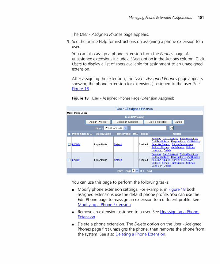
Managing Phone Extension Assignments 101
The User - Assigned Phones page appears.
4 See the online Help for instructions on assigning a phone extension to a user.
You can also assign a phone extension from the Phones page. All unassigned extensions include a Users option in the Actions column. Click Users to display a list of users available for assignment to an unassigned extension.
After assigning the extension, the User - Assigned Phones page appears showing the phone extension (or extensions) assigned to the user. See Figure 18.
Figure 18 User - Assigned Phones Page (Extension Assigned)
You can use this page to perform the following tasks:
■ Modify phone extension settings. For example, in Figure 18 both assigned extensions use the default phone profile. You can use the Edit Phone page to reassign an extension to a different profile. See Modifying a Phone Extension.
■ Remove an extension assigned to a user. See Unassigning a Phone Extension.
■ Delete a phone extension. The Delete option on the User - Assigned Phones page first unassigns the phone, then removes the phone from the system. See also Deleting a Phone Extension.
102 CHAPTER 6: MANAGING VCX PHONE PROFILES AND EXTENSIONS
■ Modify the MAC address or lock status associated with the phone extension. Click the link in the MAC column. See Configuring Media Access Control.
■ Prevent anonymous calls from reaching users. Click Call Restrictions in the Actions column and see Blocking Anonymous Callers.
■ View phone registration information, such as the IP address assigned to the phone. Click Registrations in the Actions column and see Viewing Phone Registration Information.
■ Prevent specific incoming and outgoing calls for a phone. Click Call Restrictions in the Actions column and see Configuring Phone Call Restrictions.
■ View the call history for a phone. Click Call History and see Viewing Call History.
■ Change the default ring tone for the phone, for a hunt group, or for a bridged line. Click Selective Ringing and see Configuring Selective Ringing.
■ View the hunt group (or groups) to which an extension is assigned. Click Hunt Groups and see Configuring Hunt Groups and Attendants.
■ Override phone settings (such as date and time format, and ring tones) configured by a user through the VCX User web interface. Click Settings and see Modifying a User’s Phone Settings.
The other options in the Actions column (Features, Call Coverage, Button Mappings, Bridge Permissions, and Bridged Phones) are described in Chapter 9.
Unassigning a PhoneExtension
This section describes how to remove one or more phone extensions assigned to a user.
Note that, if an assigned user extension belongs to a group (for example, a hunt group) or has an association with another phone (for example, is bridged to another extension), you must delete the membership or remove the association before you can unassign the extension. VCX software generates a warning message if it cannot unassign an extension.
To unassign a phone extension:
1 Select Users Menu > Users > Users.
The Users page appears.

Managing Phone Extension Assignments 103
2 Locate the user to whom you want to assign a phone extension.
3 In the Phones column, click the Phones link for the user.
The User - Assigned Phones page appears.
4 See the online Help for instructions on unassigning a phone extension.
User RoamingServices
With VCX software version 7.1, a user can log in to any phone in the system regardless of the call processor to which the phone is connected. In previous versions of VCX software, a user could only log in to a phone connected to call processor on which the phone extension was configured.
The processor on which the phone extension is configured is referred to as the home call processor. All other processors in the VCX system are referred to as foreign call processors.
To log in to a phone connected to a foreign call processor, a user enters his or her phone extension and password through the Telephone User Interface (TUI). The preconfigured (foreign) primary and secondary call processor IP addresses on the phone are not changed. The foreign call processor routes user requests back to the home call processor. Note that each roaming user is allowed one registered device at each remote location.
If the foreign call processor cannot contact the home call processor, the user is denied access to the system because password verification is not possible.
If the user's home call processor becomes unavailable after the user has logged in, the foreign call processor deactivates the phone and only allows outgoing emergency calls.
With the following possible exceptions, all phone features work for a roaming user as they would if that user was connected to the home call processor:
■ Emergency Calls — There are several important implications for emergency calls made by a roaming user. See Emergency Calling Considerations for Roaming Users.
■ Group Paging — Group paging may or may not work depending on the router configuration in the path between the foreign call

104 CHAPTER 6: MANAGING VCX PHONE PROFILES AND EXTENSIONS
processor and the home call processor. Routers must be configured for multicast pass through to enable group paging.
■ Number Translation — If you have set up number translation and source-based routing for calls originating from a user’s home call processor (configured as an indirect requestor), the settings will not work when the user roams. To enable number translation to work on a foreign call processor for a roaming user, you must configure the same number translation, enable source-based routing, and specify the IP address of the foreign call processor as the indirect requestor. See Configuring Number Translation Patterns.
Modifying a User’s Phone Settings
The phone settings for an extension are initially set by the phone profile used by the extension (see Creating a Phone Profile).
You can modify the following phone profile options for individual extensions on the User Phone Settings page:
■ The number of lines available for incoming and outgoing calls (referred to as System Appearance, or SA, lines). All phones must have at least one SA line. The application of the Number of Lines field value depends on the phone model:
■ For the Model 3101 Telephone, if Number of Lines value is more than two, then the number of SA lines is set to two (the maximum supported by this phone model). Otherwise, the number of SA lines is set to the value in Number of Lines.
■ For the Model 3103 Telephone, the Number of Lines value indicates how many of the 3103 lines are SA lines.
■ For the Model 2102 and Model 3102 Telephones, the Number of Lines value indicates the maximum number of lines that can be mapped to SA lines on the 2102 and 3102 button mapping pages.
■ Date and time formats
■ Ring tones for call waiting, inside, private, and outside calls
■ Call fallback
This page also includes a field (Number of Bridged Lines) that specifies the number of bridged lines an extension can use. This field is dependent on the Number of Lines field. See Configuring Bridged Extensions for more information.
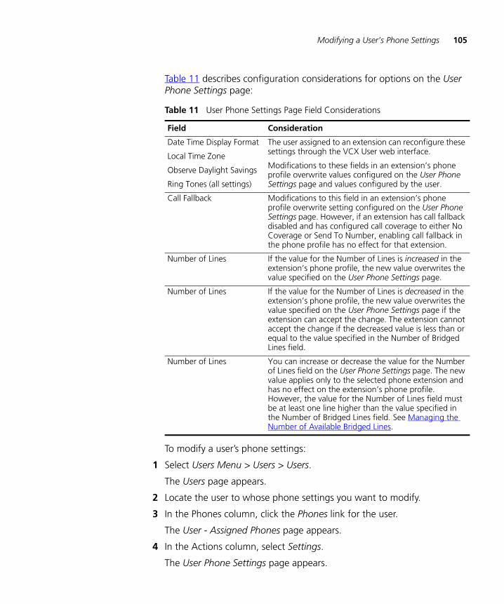
Modifying a User’s Phone Settings 105
Table 11 describes configuration considerations for options on the User Phone Settings page:
To modify a user’s phone settings:
1 Select Users Menu > Users > Users.
The Users page appears.
2 Locate the user to whose phone settings you want to modify.
3 In the Phones column, click the Phones link for the user.
The User - Assigned Phones page appears.
4 In the Actions column, select Settings.
The User Phone Settings page appears.
Table 11 User Phone Settings Page Field Considerations
Field Consideration
Date Time Display Format
Local Time Zone
Observe Daylight Savings
Ring Tones (all settings)
The user assigned to an extension can reconfigure these settings through the VCX User web interface.
Modifications to these fields in an extension’s phone profile overwrite values configured on the User Phone Settings page and values configured by the user.
Call Fallback Modifications to this field in an extension’s phone profile overwrite setting configured on the User Phone Settings page. However, if an extension has call fallback disabled and has configured call coverage to either No Coverage or Send To Number, enabling call fallback in the phone profile has no effect for that extension.
Number of Lines If the value for the Number of Lines is increased in the extension’s phone profile, the new value overwrites the value specified on the User Phone Settings page.
Number of Lines If the value for the Number of Lines is decreased in the extension’s phone profile, the new value overwrites the value specified on the User Phone Settings page if the extension can accept the change. The extension cannot accept the change if the decreased value is less than or equal to the value specified in the Number of Bridged Lines field.
Number of Lines You can increase or decrease the value for the Number of Lines field on the User Phone Settings page. The new value applies only to the selected phone extension and has no effect on the extension’s phone profile. However, the value for the Number of Lines field must be at least one line higher than the value specified in the Number of Bridged Lines field. See Managing the Number of Available Bridged Lines.

106 CHAPTER 6: MANAGING VCX PHONE PROFILES AND EXTENSIONS
5 See the online Help for instructions on modifying a user’s phone settings.
Viewing Phone Registration Information
When a user logs in to a phone (specifies the extension number and enters a password), the phone registers with the VCX call processor. You can view phone registration information such as the phone extension, IP address assigned to the phone, and when the current registration will expire.
The Phone Registrations page contains information available for each phone registration. For example, if a user has logged into two phones using the same extension, the Phone Registrations page contains two rows of information (one for each registration).
Note that, if the user is not logged in, the phone extension is not registered and the Phones Registrations page displays no information.
The Phone Registrations page displays a link, Logout, that allows you to delete the registration by logging out the phone extension. If you click the Logout link, the phone becomes unregistered and all the fields on the Phone Registrations page are cleared (you may need to refresh the page).
The Phone Registrations page also includes a Logout All button if the phone extension has at least one registration. Click Logout All to delete all phone registrations and disable all login sessions.
To view an extension’s registration information:
1 Select Users Menu > Users > Users.
The Users page appears.
2 Click Phones in the Phones column for the end user whose phone registrations you want to view.
The User - Assigned Phones page appears.
3 In the Actions column, click Registrations.
The Phones Registrations page appears. See Figure 19.

Viewing Phone Registration Information 107
Figure 19 Phone Registrations Page
Table 12 lists each column name and describes the type of information displayed in that column.
Table 12 Phone Registrations Page
Column Description
Priority Specifies the registration priority for the phone registration.
End Time Specifies the expiration time for the phone registration. The expiration timer is determined by the Registration Interval value entered on the Phone Profile page (see Creating a Phone Profile).
Deletable Indicates whether the phone registration is a Provisioning (static) or Dynamic contact.
User Name Specifies the phone extension.
Host Specifies the IP address assigned to the phone.
Port Specifies the port number on the call processing server.
Type Indicates the type of phone registration (for VCX phones, the value is SIP).
Locked Indicates whether the extension is locked to a phone’s hardware (MAC) address (see Configuring Media Access Control). When locked, the phone cannot be programmed with a different extension. Also, you cannot use the logout options on this page (see Action, below) to log out a phone with a locked extension.

108 CHAPTER 6: MANAGING VCX PHONE PROFILES AND EXTENSIONS
Viewing Call History
You can use the Call History page to view the most recent calls placed to and from a particular phone extension (up to 100 calls).
To view the call history for a phone:
1 Select Users Menu > Users > Users.
The Users page appears.
2 Click Phones in the Phones column.
The User - Assigned Phones page appears.
3 Click Call History in the Actions column.
The Call History page appears. See Figure 20.
Action Displays a link, Logout, that allows you to delete the registration by logging out the phone extension. If you click the Logout link, the phone becomes unregistered and all the fields on the Phone Registrations page are cleared (you may need to refresh the page).
The Phone Registrations page also includes a Logout All button if the phone extension has at least one registration (the extension is logged in to a call processor). Click Logout All to delete all phone registrations and disable all login sessions.
Note: You can only use the Logout function to delete the registration 3Com IP-enabled phones. You cannot use the button to log out other end points (for example, analog phones connected to an FXS gateway).
Table 12 Phone Registrations Page (continued)
Column Description

Viewing Call History 109
Figure 20 Call History Page
The Call History page contains three columns of information for both Incoming and Outgoing calls. You can sort the calls in each category (Incoming and Outgoing) by clicking the Date or Time column header. If the log contains more calls than the interface can display on a page, click Next or Previous to navigate between pages. See Using the Graphical User Interface.
Table 13 lists each column and describes the type of information available in that column.
4 To return to the User - Assigned Phones page, click Cancel.
Table 13 Call History Information for Phones
Main Column Sub Columns Description
Incoming Date This field contains the date when a call was received using the YYYY-MM-DD format.
Time This field contains the time a call ended.
Calling Party This field contains the extension of the phone that initiated a specific call.
Outgoing Date This field contains the date when a call was initiated using the YYYY-MM-DD format.
Time This field contains the time a call ended.
Called Party This field contains the extension of the phone who received a specific call.
110 CHAPTER 6: MANAGING VCX PHONE PROFILES AND EXTENSIONS
Configuring Media Access Control
Each VCX telephone in the system has a unique Media Access Control (MAC) address, which is printed on the bottom of the telephone. You can lock a phone’s MAC address to a particular phone extension.
Locking a MAC address to a phone extension has the following consequences:
■ Prevents use of a different extension on the telephone because access to the Telephone User Interface (TUI) on the phone is blocked and the phone cannot be reprogrammed.
■ Enables the phone to automatically learn its assigned extension and log in when the phone is powered on (booted).
Locking a MAC address to a phone extension does not, however, prevent another phone from using the same extension.
If you lock an extension to a phone’s MAC address and the phone is logged in to the VCX system, you must reboot (power off/power on) the phone for the lock to take effect.
To associate a MAC address with a phone extension, edit the MAC address association, or remove the MAC address association:
1 Select Users Menu > Devices > Media Access Control.
The Media Access Control page appears.
2 See the online Help for instructions on managing a MAC address association.
Configuring an Attendant Console
The VCX Attendant Console (Model 3105) enables an attendant to handle high call volumes efficiently. The attendant could be a receptionist, administrative assistant, busy sales representative, or anyone who receive a high volume of telephone calls or who make frequent calls to the same telephone numbers.
The Attendant Console is associated with the attendant’s extension. Up to three Attendant Consoles can be associated with one telephone extension. A VCX system can support a maximum of 100 attendant consoles.
User extensions are mapped to buttons on the Attendant Console. When an extension is on a call, the light next to the Attendant Console button is
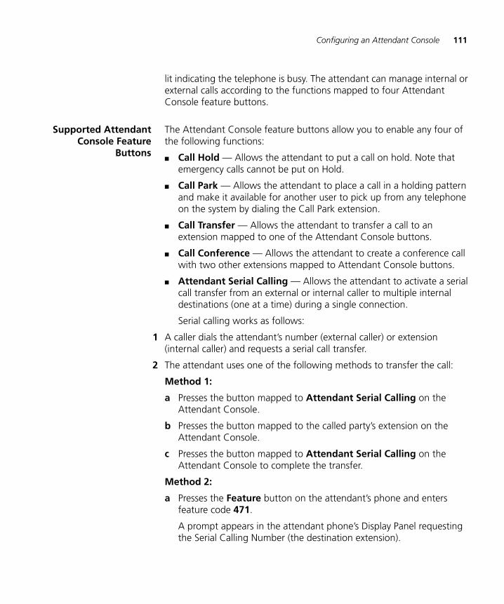
Configuring an Attendant Console 111
lit indicating the telephone is busy. The attendant can manage internal or external calls according to the functions mapped to four Attendant Console feature buttons.
Supported AttendantConsole Feature
Buttons
The Attendant Console feature buttons allow you to enable any four of the following functions:
■ Call Hold — Allows the attendant to put a call on hold. Note that emergency calls cannot be put on Hold.
■ Call Park — Allows the attendant to place a call in a holding pattern and make it available for another user to pick up from any telephone on the system by dialing the Call Park extension.
■ Call Transfer — Allows the attendant to transfer a call to an extension mapped to one of the Attendant Console buttons.
■ Call Conference — Allows the attendant to create a conference call with two other extensions mapped to Attendant Console buttons.
■ Attendant Serial Calling — Allows the attendant to activate a serial call transfer from an external or internal caller to multiple internal destinations (one at a time) during a single connection.
Serial calling works as follows:
1 A caller dials the attendant’s number (external caller) or extension (internal caller) and requests a serial call transfer.
2 The attendant uses one of the following methods to transfer the call:
Method 1:
a Presses the button mapped to Attendant Serial Calling on the Attendant Console.
b Presses the button mapped to the called party’s extension on the Attendant Console.
c Presses the button mapped to Attendant Serial Calling on the Attendant Console to complete the transfer.
Method 2:
a Presses the Feature button on the attendant’s phone and enters feature code 471.
A prompt appears in the attendant phone’s Display Panel requesting the Serial Calling Number (the destination extension).
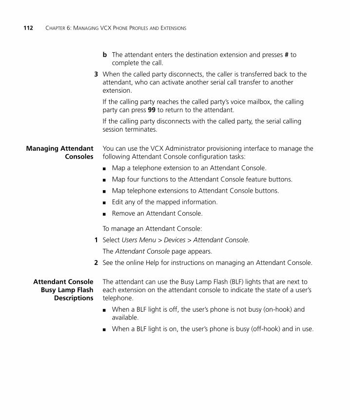
112 CHAPTER 6: MANAGING VCX PHONE PROFILES AND EXTENSIONS
b The attendant enters the destination extension and presses # to complete the call.
3 When the called party disconnects, the caller is transferred back to the attendant, who can activate another serial call transfer to another extension.
If the calling party reaches the called party’s voice mailbox, the calling party can press 99 to return to the attendant.
If the calling party disconnects with the called party, the serial calling session terminates.
Managing AttendantConsoles
You can use the VCX Administrator provisioning interface to manage the following Attendant Console configuration tasks:
■ Map a telephone extension to an Attendant Console.
■ Map four functions to the Attendant Console feature buttons.
■ Map telephone extensions to Attendant Console buttons.
■ Edit any of the mapped information.
■ Remove an Attendant Console.
To manage an Attendant Console:
1 Select Users Menu > Devices > Attendant Console.
The Attendant Console page appears.
2 See the online Help for instructions on managing an Attendant Console.
Attendant ConsoleBusy Lamp Flash
Descriptions
The attendant can use the Busy Lamp Flash (BLF) lights that are next to each extension on the attendant console to indicate the state of a user’s telephone.
■ When a BLF light is off, the user’s phone is not busy (on-hook) and available.
■ When a BLF light is on, the user’s phone is busy (off-hook) and in use.
7
VCX DATA SYNCHRONIZATIONThis chapter describes how you can enable data synchronization between a VCX IP Telephony server and an IP Messaging server.
This chapter includes the following topics:
■ About IP Telephony and IP Messaging Data Synchronization
■ Data Synchronization and Phone Profiles
■ Data Synchronization and Logging

114 CHAPTER 7: VCX DATA SYNCHRONIZATION
About IP Telephony and IP Messaging Data Synchronization
A VCX system can include call processing services and messaging services.
The call processing services (for example, phone extensions, user accounts, dial plans, and call routing) are provided by a VCX IP Telephony server.
The messaging services (for example, voice mailboxes, unified messaging, and auto attendants) can be provided by an IP Messaging server.
VCX software can synchronize some of the data configured on a VCX IP Telephony server by exporting the data to an IP Messaging server. The synchronization includes both system data and user data. (Hunt group data can also be synchronized; see Data Synchronization and Hunt Groups in Chapter 11.)
■ System data includes:
■ The voicemail number the call processor dials to access voicemail services on the IP Messaging server.
■ The Music on Hold (MOH) number the call processor dials to access MOH when a user puts a caller on hold. The caller hears the audio file (music or a recording) associated with the MOH number.
■ The MOH file that contains the audio (music or a recording) associated with the MOH number.
■ User data includes:
■ The voice mailbox associated with a telephone extension.
■ The password used to access a mailbox.
■ The IP Messaging Class of Service (COS) that defines the permissions and features enabled for a set of mailboxes.
■ User account information (first name, last name).
System or user data created or modified through the VCX Administrator web provisioning interface can be exported to the IP Messaging server. However this synchronization flow is one-way; data created or modified through an IP Messaging provisioning interface is not exported to the IP Telephony server.
The IP Messaging server receives IP Telephony data through event-driven updates. When a data change occurs on the IP Telephony server, a
About IP Telephony and IP Messaging Data Synchronization 115
notification is sent to the IP Messaging server. The IP Messaging server then pulls the data from the active data server.
The initial data export from the IP Telephony server to the IP Messaging server occurs after the following sequence of events:
1 You create and save a phone profile with the Enable Voicemail check box enabled. The phone profile specifies a voicemail access number (new or existing), MOH number (new or existing), MOH audio file (existing), and an IP Messaging Class of Service (existing).
After a few minutes, the data is exported to the IP Messaging server. If the voicemail access number or MOH number are new, the IP Messaging server creates either or both numbers.
2 You create a telephone extension and assign it to the phone profile.
3 You create a user profile and assign the extension to the user.
After a few minutes, the data is exported to the IP Messaging server. The IP Messaging server now has a new voice mailbox assigned to the phone extension. The voice mailbox also has the following associations:
■ A voice mailbox password based on password assigned to the phone extension created in step 2 above.
■ A new user account based on the user profile information created in step 3 above.
■ The IP Messaging Class of Service (COS) specified in the phone profile created in step 1 above.
■ The voicemail access number specified in the phone profile information created in step 1 above. When the user presses the messages button on the phone, the VCX call processor automatically dials the voicemail access number.
■ The MOH number specified in the phone profile information created in step 1 above. The MOH number is associated with the specified MOH audio file. When the user presses the Hold button on the phone, the VCX call processor places the caller on hold, automatically dials the MOH number, and the IP Messaging sever plays the audio file.

116 CHAPTER 7: VCX DATA SYNCHRONIZATION
Data Synchronization and Phone Profiles
Data synchronization between IP Telephony and IP Messaging is controlled by the Enable Voicemail check box on the Phone Profile page of the VCX Administrator web provisioning interface (see the online Help).
■ If the Enable Voicemail check box is enabled, IP Messaging automatically creates a voice mailbox for each extension assigned to the profile and assigned to a user. System and user data configured on the Phone Profile page, and user data configured on the User page, is exported to IP Messaging.
■ If the Enable Voicemail check box is disabled, IP Messaging does not create a mailbox for extensions assigned to the profile, and no data is exported to IP Messaging.
Note that there are rules and restrictions on how data is exported to IP Messaging, which are described in System Data Synchronization and User Data Synchronization. For example, data exported to an IP Messaging server from a phone profile cannot be modified or deleted using an IP Messaging provisioning interface.
Automatic mailbox creation through data synchronization is subject to VCX software license rules introduced in the v8.0 release. You must have sufficient license keys to support the number of phones and mailboxes on your system. See the VCX Maintenance Guide for detailed information.
For VCX software version 8.0, the Phone Profile page includes two new fields, IPM COS (specifies an IP Messaging Class of Service) and Music on Hold File (specifies the audio file used by the MOH number).
■ If you have updated your VCX system to version 8.0 from a previous release, your existing phone profiles retain their previous field values. The new phone profile fields are assigned the following values:
■ The new IPM COS field is assigned the default IP Messaging Class of Service (102).
■ The new Music on Hold File field is assigned the default IP Messaging MOH file (music).
■ If this is a new VCX installation, VCX software includes several sample phone profiles (see VCX Connect Sample Phone Profiles). Some of the sample profiles enable the Enable Voicemail check box in which case the following default field values are configured:
Data Synchronization and Phone Profiles 117
■ The IPM COS field is assigned the default IP Messaging Class of Service (102).
■ The Voice Mail Number field is assigned the number 5000.
■ The Music on Hold Number field is assigned the number 5001.
■ The Music on Hold File field is assigned the default IP Messaging MOH file (music).
System DataSynchronization
VCX software can synchronize system data on a VCX IP Telephony server by exporting the data to an IP Messaging server. This system data is configured on the VCX Administrator web provisioning interface Phone Profile page. It is considered system data because it applies to all extensions assigned to the phone profile.
If the Enable Voicemail check box is enabled on the Phone Profile page, the following system data is synchronized with IP Messaging:
■ The voicemail number the call processor dials to access voicemail services on the IP Messaging server.
If the number is not already configured on the IP Messaging server, the IP Messaging software creates it.
If the number is already configured on the IP Messaging server, the phone profile uses the existing number.
■ The Music on Hold (MOH) number the call processor dials to access MOH when a user puts a caller on hold. The caller hears the audio file (music or a recording) associated with the MOH number.
If the number is not already configured on the IP Messaging server, the IP Messaging software creates it.
If the number is already configured on the IP Messaging server, the phone profile uses the existing number.
■ The MOH file that contains the audio (music or a recording) associated with the MOH number.
The MOH file field on the Phone Profile page lists all the audio files available for use with the MOH number. You must select an existing file.
■ The IP Messaging Class of Service (COS) that defines the permissions and features enabled for a set of mailboxes.

118 CHAPTER 7: VCX DATA SYNCHRONIZATION
The IPM COS field on the Phone Profile page lists all the IP Messaging Classes of Service available for use with the MOH number. You must select an existing COS.
A voicemail access number or a MOH number/MOH file association that has been exported to IP Messaging from a phone profile is retained in IP Messaging even if you delete the phone profile.
You cannot use a IP Messaging provisioning interface to modify a voicemail access number or a MOH number/MOH file association that has been imported from a phone profile. While the interface allows the modification, during the next data synchronization operation, the modification is overwritten with the original value. Similarly, you cannot use a IP Messaging provisioning interface to delete a voicemail access number or a MOH number that has been imported from a phone profile.
User DataSynchronization
VCX software can synchronize user data on a VCX IP Telephony server by exporting the data to an IP Messaging server. This user data is configured on the VCX Administrator web provisioning interface Phone Profile, User, and Phone pages.
As described in Data Synchronization and Phone Profiles, synchronization is controlled by the Enable Voicemail check box on the Phone Profile page. If enabled, the user data shown in Table 14 is synchronized with IP Messaging.
Table 14 Synchronized User Data
VCX Administrator Web Provisioning Interface Page Field Description/Comments
Add Phone Profile or Modify Phone Profile page
IPM COS Defines the permissions and features enabled for a mailbox.
When you select a listed COS, IP Messaging uses that Class of Service for all mailboxes associated with the phone profile.

Data Synchronization and Phone Profiles 119
Note the following user data synchronization considerations:
■ When the Enable Voicemail check box on the Phone Profile page is enabled, the mailbox is created and data synchronization occurs. Any subsequent changes to synchronized user data made through the VCX Administrator web provisioning interface are exported to IP Messaging. If you then disable the Enable Voicemail check box, synchronization stops and subsequent changes are not exported until you re-enable the Enable Voicemail check box. Note that disabling synchronization has no effect on existing mailboxes—they function normally and are accessible.
Disabling the Enable Voicemail check box on a Phone Profile page prevents mailbox access for all users whose phone extensions are assigned to the that profile.
■ A mailbox is not created in IP Messaging until the phone extension created in the VCX Administrator web provisioning interface is assigned to a user.
■ You can also create voice mailboxes using an IP Messaging provisioning interface. If you create a phone extension and assign it to a user, and the phone extension duplicates a number already assigned to an IP Messaging mailbox, the user data associated with the phone extension overwrites any user data configured in IP Messaging. This
Add Phone or Modify Phone page
Phone Extension Specifies the telephone extension, assigned to a user, that is used to create a voice mailbox in IP Messaging.
Phone Password Specifies the password used to access a mailbox. Initially, this password is identical to the password used to log in to a telephone (see Password Synchronization).
Add User or Modify User page
First Name Specifies the first name of the user.
Only the first 20 characters are exported to IP Messaging.
Last Name Specifies the last name of the user.
Only the first 20 characters are exported to IP Messaging.
Table 14 Synchronized User Data (continued)
VCX Administrator Web Provisioning Interface Page Field Description/Comments

120 CHAPTER 7: VCX DATA SYNCHRONIZATION
also occurs if you modify a VCX phone extension so that it duplicates an existing IP Messaging mailbox number.
■ If you unassign a phone extension for a user, the mailbox associated with that extension remains accessible. If you reassign the extension to a different user, data synchronization updates the corresponding mailbox in IP Messaging with information for the new user.
■ If you change the phone profile used by a phone extension, data synchronization updates the corresponding mailbox in IP Messaging.
You cannot use a IP Messaging provisioning interface to modify user data (mailbox number or any of the data shown in Table 14) that has been exported from a IP Telephony server. While the interface allows the modification, during the next data synchronization operation, the modification is overwritten with the original value. Similarly, you cannot use a IP Messaging provisioning interface to delete imported user data.
Password Synchronization
Both IP Telephony and IP Messaging require user passwords.
The IP Telephony password is associated with a phone extension. The user enters this password on the telephone keypad to log in to the telephone.
The IP Messaging password is associated with a voice mailbox number. The user enters this password on the telephone keypad to access a mailbox. Depending on the IP Messaging configuration, the user may also be prompted to enter the mailbox number.
When you create a phone extension, you specify an extension number, a phone password, and a phone profile. If the phone profile Enable Voicemail check box is enabled, IP Messaging automatically creates a voice mailbox for the extension with the following attributes:
■ The phone extension number is imported and used as the mailbox number.
■ The phone password is imported and used as the mailbox password.
At this point, the phone password and the mailbox password are synchronized (identical).
The first time the user accesses the mailbox, IP Messaging prompts the user for a password. The user enters the phone password and IP Messaging authenticates the user. Once authenticated, IP Messaging
Data Synchronization and Logging 121
prompts the user to change the mailbox password. As soon as the user changes the mailbox password, the phone password and the mailbox password are no longer synchronized. If the VCX administrator changes the phone password, the change is ignored by IP Messaging.
Data Synchronization and Logging
Data synchronization events generated by successful or failed attempts to export data from an IP Telephony server to an IP Messaging server are logged on the IP Messaging server.
The IP Messaging server logs the following events:
■ Each notification it receives from the IP Telephony server
■ Each fetched file result
■ All changes made to the local IP Messaging server
Events are logged in the following file:
/usr/app/subscriber_import.log
For more information on logging, see Viewing the Event Logs and also see the VCX Maintenance Guide.

122 CHAPTER 7: VCX DATA SYNCHRONIZATION

8
CONFIGURING TELEPHONE COMMUNICATION SETTINGSThis chapter describes configuration options available through a utility on the phone called the Local User Interface (LUI). The LUI menu allows you to view and configure phone settings such as the phone extension and the IP address of the call processor.
Refer to the VCX Installation Guide for information on how to install and initially configure all supported 3Com VCX devices.
This chapter includes the following topics:
■ 3Com Telephone Configuration
■ 3Com Telephone Local User Interface Menus
124 CHAPTER 8: CONFIGURING TELEPHONE COMMUNICATION SETTINGS
3Com Telephone Configuration
There are multiple configuration steps required to enable a VCX telephone to work within a VCX system. These steps are described in various chapters of this guide (see Chapter 1 for an overview).
As described in the VCX Installation Guide, each 3Com telephone in a VCX system must be configured with the IP address of the primary Call Processor (also called a Network Call Processor or NCP) and the IP address of the secondary NCP. When connected to the network and powered on, this enables the phone to contact the NCP and download the following information:
■ Signaling software that enables the phone to make and receive calls.
■ Operational software that determines what features are available based on the model of the phone.
■ An IP address that establishes the phone as an IP device and allows it to communicate with other IP devices using the Session Initiation Protocol (SIP).
The phone will automatically receive an IP address only if your network includes a DHCP server configured with Option 184. If DHCP is not available, you must manually configure IP address information on the phone.
When the download process finishes, the phone prompts for the following information:
■ The extension that other phones will dial to communicate with the phone. The extension is associated with an account that identifies the user who can use the phone. If the phone was assigned an extension when the NCP IP addresses were configured, this prompt is not displayed.
■ A password the user enters to log in to the phone.
Initial telephone configuration, including DHCP setup, is described in the VCX Installation Guide. This chapter describes how to use the LUI to view and change current settings for all supported VCX telephone models.
■ See 3Com Telephone Local User Interface Menus for the following 3Com VCX telephones:
■ Model 3102 Business Telephone
■ Model 3101 or 3101SP Basic Telephones
3Com Telephone Local User Interface Menus 125
■ Model 2102 and 2102-IR Business Telephones
VCX Connect does not support the 3Com Model 2102 and 2102-R Business Telephones.
If a VCX release includes new phone application or boot code, all VCX phones connected to the system will upgrade automatically. Every 30 minutes each phone sends a message to the VCX Call Server that includes the software version running on the phone. If a different version has been installed on the server, then a code download to the phone is initiated.
3Com VCX telephone models are identified by a product number on the label affixed under each phone. For example, the following product number identifies a Model 3102 Business Telephone: 3C10402B. For each 3Com telephone the letter B indicates the latest version of that model. Older models have the letter A appended to the product number (for example, 3C10402A).
3Com telephones with a product number that ends with the letter B and that operate in a redundant VCX system must download phone software from the primary server. If, in rare circumstances, a model B phone has failed over to the secondary server, no software download is possible until the phone re-registers with the primary server.
3Com Telephone Local User Interface Menus
The firmware within each 3Com telephone includes a telephone diagnostic and configuration utility called the Local User Interface (LUI). The administrator has access to telephone configurable parameters through the LUI, which are needed for initial physical telephone configuration, any required reconfiguration, and to test the telephone.
The LUI access enables you to perform these tasks:
■ View telephone settings, both the active settings and the settings stored in the telephone’s memory.
■ Set telephone IP address, subnet mask, and default gateway.
■ Specify IP address of the Network Call Processors (NCPs).
■ Test the telephone buttons, display panel, and LEDs.
■ Clear all device settings.
■ View firmware information and diagnostics (technician option).
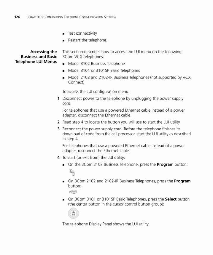
126 CHAPTER 8: CONFIGURING TELEPHONE COMMUNICATION SETTINGS
■ Test connectivity.
■ Restart the telephone.
Accessing theBusiness and Basic
Telephone LUI Menus
This section describes how to access the LUI menu on the following 3Com VCX telephones:
■ Model 3102 Business Telephone
■ Model 3101 or 3101SP Basic Telephones
■ Model 2102 and 2102-IR Business Telephones (not supported by VCX Connect)
To access the LUI configuration menu:
1 Disconnect power to the telephone by unplugging the power supply cord.
For telephones that use a powered Ethernet cable instead of a power adapter, disconnect the Ethernet cable.
2 Read step 4 to locate the button you will use to start the LUI utility.
3 Reconnect the power supply cord. Before the telephone finishes its download of code from the call processor, start the LUI utility as described in step 4.
For telephones that use a powered Ethernet cable instead of a power adapter, reconnect the Ethernet cable.
4 To start (or exit from) the LUI utility:
■ On the 3Com 3102 Business Telephone, press the Program button:
■ On 3Com 2102 and 2102-IR Business Telephones, press the Program button:
■ On 3Com 3101 or 3101SP Basic Telephones, press the Select button (the center button in the cursor control button group):
The telephone Display Panel shows the LUI utility.

3Com Telephone Local User Interface Menus 127
See LUI Configuration Options for Business and Basic Telephones for a description of the configuration menu options.
See Business and Basic Telephone Interfaces for a description of the buttons you use to enter configuration information.
Accessing theManager’s Telephone
LUI Menus
You can access the LUI utility on the 3Com 3103 Manager’s Telephone when the phone is connected to, or disconnected from, the VCX network.
To access the LUI utility when the Manager’s Telephone is disconnected from the network:
a Disconnect the power connector.
b Unplug the network (Ethernet) cable.
c Reconnect the power connector.
The 3103 Display Panel shows the following message:
No Network Connection! Please Connect Cable or Press Feature to Manually Configure
d Press the button under the Feature tab.
To access the LUI utility when the Manager’s Telephone is connected to the network:
a Press the button under the Feature tab.
b Use the Down button to scroll to the User Configurations menu option.
c Select User Configurations and press the button under the Select tab.
The telephone Display Panel shows the LUI utility.
See LUI Configuration Options for the Manager’s Telephone for a description of the configuration menu options.
See Manager’s Telephone Interface for a description of the buttons you use to enter configuration information on a Model 3103 telephone.

128 CHAPTER 8: CONFIGURING TELEPHONE COMMUNICATION SETTINGS
Business and BasicTelephone Interfaces
Button operation, location, and menu options are similar for the Model 3102 Business Telephone, the Model 3101 or 3101SP Basic Telephones, and the Model 2102 and 2102-IR Business Telephones. Topics in this section describe each telephone model.
VCX Connect does not support the 3Com Model 2102 and 2102-R Business Telephones.
Model 3102 Business Telephone LUI Controls
Figure 21 shows the LUI controls on the Model 3102 Business Telephone. Table 15 describes each LUI utility menu item.
Figure 21 Local User Interface Controls on the 3Com 3102 Business Telephone
1 Display Panel — Shows LUI utility menu options. Use the scroll buttons (see number 6) to navigate through the list of options.
2 Soft Buttons — Moves the cursor left or right. The middle button is not used.
3 Key Pad — Selects menu items or enter numeric characters in a configuration option. Use the # key to save changes after you edit an item.
4 Access Buttons AB1-AB4 — Selects LUI menu items (AB4 is topmost, AB1 is on the bottom).
5 Program Button — Functions as follows:
3Com Test MenuScroll-- Options
1
2
5
3
6
4

3Com Telephone Local User Interface Menus 129
■ Starts and exits from the LUI utility.
■ Exits from a menu item and moves to the next higher menu. If you press Program before you save a change to a setting, you exit the menu item without saving the change.
6 Scroll Buttons — Function as follows:
■ Up and Down Buttons — Moves up or down through the LUI menu and select hex digits when editing a MAC address.
■ Left and Right Buttons — Positions the cursor in the Display Panel when editing a setting, such as an IP address.
Model 3101 and 3101SP Basic Telephones LUI Controls
Figure 22 shows the LUI controls on the Model 3101and 3101SP Basic Telephones. Table 15 describes each LUI utility menu item.
Figure 22 Local User Interface Controls on 3Com 3101 and 3101SP Basic Telephones
1 Display Panel — Shows LUI utility menu options. Use the scroll buttons (see number 5) to navigate through the list of options.
2 Soft Buttons — Moves the cursor left or right. The middle button is not used.
3 Key Pad — Selects menu items or enter numeric characters in a configuration option. Use the # key to save changes after you edit an item.
NBX Test Menu
Scroll--Options1
2
3
4
5
3Com Test MenuScroll-- Options
130 CHAPTER 8: CONFIGURING TELEPHONE COMMUNICATION SETTINGS
4 Access Buttons AB1-AB4 — Selects LUI menu items. The buttons are numbered left to right (AB1 is the first button on the left, AB4 is the last button on the right).
5 Scroll Buttons — Function as follows:
■ Select Button — The center (Select) button starts and exits from the LUI utility, or exits from a menu item and moves to the next higher menu. If you press Select before you save a change to a setting, you exit the menu item without saving the change.
■ Up and Down Buttons — Moves up or down through the LUI menu and select hex digits when editing a MAC address.
■ Left and Right Buttons — Positions the cursor in the Display Panel when editing a setting, such as an IP address.
Model 2102 and 2102SP Business Telephones LUI Controls
Figure 23 shows the LUI controls on the Model 2102 and 2102-IR Business Telephones. Table 15 describes each LUI utility menu item.
VCX Connect does not support the 3Com Model 2102 and 2102-R Business Telephones.

3Com Telephone Local User Interface Menus 131
Figure 23 Local User Interface Controls on the 3Com 2102 and 2102-IR Business Telephones
1 Display Panel — Shows LUI utility menu options. Use the scroll buttons (see number 6) to navigate through the list of options.
2 Soft Buttons — Moves the cursor left or right. The middle button is not used.
3 Program Button — Starts and exits from the LUI utility, or exits from a menu item and moves to the next higher menu. If you press the Program button before you save a change to a setting, you exit the menu item without saving the change.
4 Key Pad — Selects menu items or enter numeric characters in a configuration option. Use the # key to save changes after you edit an item.
5 Access Buttons AB1-AB4 — Selects LUI menu items (AB1 is topmost, AB4 is on the bottom).
6 Scroll Buttons — Moves up or down through the LUI menu and select hex digits when editing a MAC address.
LUI Configuration Options for Business and Basic Telephones
Table 15 describes each LUI utility menu item that appears in the LUI for the Business and Basic Telephones.
3Com Test Menu Scroll--Options1
2
3
4
6
5

132 CHAPTER 8: CONFIGURING TELEPHONE COMMUNICATION SETTINGS
Table 15 Business and Basic Telephone LUI Menu Items
Menu Option Description
1 View Settings Press 1 on the number pad and scroll to view these options:
MAC Address – MAC address of this telephone.
NCP MAC Address – MAC address of the primary call processor.
SW Build Ident. – Software version running on this telephone.
Serial # Rev – Telephone serial number and hardware version.
Phone Port Speed – Speed and duplex setting of the LAN connection.
PC Port Speed – The speed and duplex setting of the PC port to the device, if any, connected to the port.
My IP Address – Active IP address of this telephone.
Subnet Mask – Active IP mask.
Gatwy IP Address – Active default gateway IP address.
NCP IP Address – Active IP address of the call processor with which this telephone communicates.
ALT SrvrIP – Active IP address of the secondary call processor.
VLAN Config – Enabled or disabled VLAN for this telephone, acquired from either DHCP option 184 or a setting in the telephone’s memory.
Mem- My IP Addr – The IP address configured in the telephone’s memory though the LUI utility.
Mem- Subnet Mask – The IP mask configured in the telephone’s memory though the LUI utility.
Mem- Gatwy IP – The default gateway IP address configured in the telephone’s memory though the LUI utility.
Mem- NCP IP Addr – The NCP IP address configured in the telephone’s memory though the LUI utility.
Mem- ALT SrvrIP – Secondary download server address configured in the telephone’s memory.
Mem- VLAN Config – VLAN values configured in telephone’s memory.

3Com Telephone Local User Interface Menus 133
2 Set my IP
3 Set SubNMsk
4 Set Gatwy IP
Lets you specify the IP information for this telephone. If you have a DHCP server, this information is automatically provided by the server.
When entering an IP address:
■ Use the key pad to enter digits 0–9.
■ Use the left and right soft keys or scroll keys to move the cursor left or right.
■ If any of the fields within the IP address contain only one or two digits, add leading zeros.Example: Enter 10.234.1.125 as 010.234.001.125
■ To change a telephone back to its default setting, enter 255 for each octet of the IP address. To clear all configured settings and return to factory defaults, select menu item 0 (EEPROM-default).
■ Press the # key to commit your address change.
5 Set NCP IP Lets you specify the IP address of the primary Network Call Processor. This information is typically provided by using a DHCP server configured with option 184. You can, however, manually enter the IP address.
When entering an IP address:
■ Use the key pad to enter digits 0–9.
■ Use the left and right soft keys or scroll keys to move the cursor left or right.
■ If any of the fields within the IP address contain only one or two digits, add leading zeros.Example: Enter 10.234.1.125 as 010.234.001.125
■ To change a telephone back to its default setting, enter 255 for each octet of the IP address. To clear all configured settings and return to factory defaults, select menu item 0 (EEPROM-default).
■ Press the # key to commit your address change.
Table 15 Business and Basic Telephone LUI Menu Items (continued)
Menu Option Description
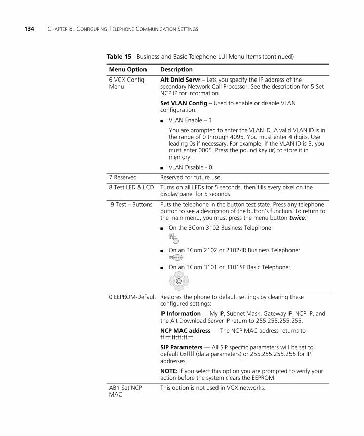
134 CHAPTER 8: CONFIGURING TELEPHONE COMMUNICATION SETTINGS
6 VCX Config Menu
Alt Dnld Servr – Lets you specify the IP address of the secondary Network Call Processor. See the description for 5 Set NCP IP for information.
Set VLAN Config – Used to enable or disable VLAN configuration.
■ VLAN Enable – 1
You are prompted to enter the VLAN ID. A valid VLAN ID is in the range of 0 through 4095. You must enter 4 digits. Use leading 0s if necessary. For example, if the VLAN ID is 5, you must enter 0005. Press the pound key (#) to store it in memory.
■ VLAN Disable - 0
7 Reserved Reserved for future use.
8 Test LED & LCD Turns on all LEDs for 5 seconds, then fills every pixel on the display panel for 5 seconds.
9 Test – Buttons Puts the telephone in the button test state. Press any telephone button to see a description of the button’s function. To return to the main menu, you must press the menu button twice:
■ On the 3Com 3102 Business Telephone:
■ On an 3Com 2102 or 2102-IR Business Telephone:
■ On an 3Com 3101 or 3101SP Basic Telephone:
0 EEPROM-Default Restores the phone to default settings by clearing these configured settings:
IP Information — My IP, Subnet Mask, Gateway IP, NCP-IP, and the Alt Download Server IP return to 255.255.255.255.
NCP MAC address — The NCP MAC address returns to ff:ff:ff:ff:ff:ff.
SIP Parameters — All SIP specific parameters will be set to default 0xffff (data parameters) or 255.255.255.255 for IP addresses.
NOTE: If you select this option you are prompted to verify your action before the system clears the EEPROM.
AB1 Set NCP MAC
This option is not used in VCX networks.
Table 15 Business and Basic Telephone LUI Menu Items (continued)
Menu Option Description
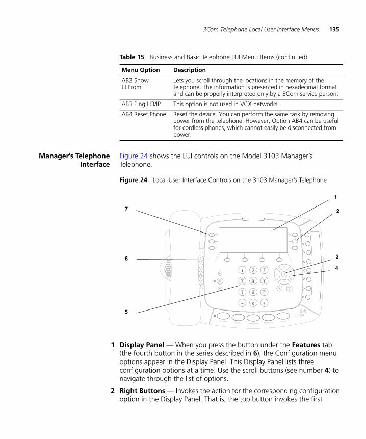
3Com Telephone Local User Interface Menus 135
Manager’s TelephoneInterface
Figure 24 shows the LUI controls on the Model 3103 Manager’s Telephone.
Figure 24 Local User Interface Controls on the 3103 Manager’s Telephone
1 Display Panel — When you press the button under the Features tab (the fourth button in the series described in 6), the Configuration menu options appear in the Display Panel. This Display Panel lists three configuration options at a time. Use the scroll buttons (see number 4) to navigate through the list of options.
2 Right Buttons — Invokes the action for the corresponding configuration option in the Display Panel. That is, the top button invokes the first
AB2 Show EEProm
Lets you scroll through the locations in the memory of the telephone. The information is presented in hexadecimal format and can be properly interpreted only by a 3Com service person.
AB3 Ping H3/IP This option is not used in VCX networks.
AB4 Reset Phone Reset the device. You can perform the same task by removing power from the telephone. However, Option AB4 can be useful for cordless phones, which cannot easily be disconnected from power.
Table 15 Business and Basic Telephone LUI Menu Items (continued)
Menu Option Description
1
2
3
4
5
6
7

136 CHAPTER 8: CONFIGURING TELEPHONE COMMUNICATION SETTINGS
option, the middle button invokes the second option, and the bottom button invokes the third option.
3 Select Button — Selects the highlighted option in a list on the Display Panel. The highlighted option is indicated by a black dot to the left of the option.
4 Scroll Buttons (Up, Down, Left, Right) — The Up and Down buttons move scroll up and down through the options shown in the Display Panel. Arrows in the display show if there are more options above or below those displayed. The options are described in Table 16.
The Left button functions as a backspace key and deletes the character to the left of the cursor position. The Right button highlights the cursor position; it does not move the cursor to the right.
5 Telephone Key Pad — Enables you to enter data required to enable a configuration option (for example, an IP address).
6 Soft buttons — Each of the four buttons activates the tabbed command shown in the Display Panel above the corresponding button. The commands change according to context. Possible options include Messages, Directory, Call Logs, Features, Exit, Cancel, Back, and Select.
7 Left Buttons — Have no function when the phone is not connected to the VCX network. When the phone is connected and configured, these buttons are used to process calls.
LUI Configuration Options for the Manager’s Telephone
Table 16 describes each Configuration menu item that appears in the LUI for the Manager’s Telephone.
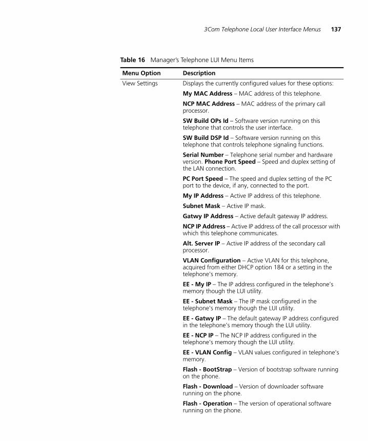
3Com Telephone Local User Interface Menus 137
Table 16 Manager’s Telephone LUI Menu Items
Menu Option Description
View Settings Displays the currently configured values for these options:
My MAC Address – MAC address of this telephone.
NCP MAC Address – MAC address of the primary call processor.
SW Build OPs Id – Software version running on this telephone that controls the user interface.
SW Build DSP Id – Software version running on this telephone that controls telephone signaling functions.
Serial Number – Telephone serial number and hardware version. Phone Port Speed – Speed and duplex setting of the LAN connection.
PC Port Speed – The speed and duplex setting of the PC port to the device, if any, connected to the port.
My IP Address – Active IP address of this telephone.
Subnet Mask – Active IP mask.
Gatwy IP Address – Active default gateway IP address.
NCP IP Address – Active IP address of the call processor with which this telephone communicates.
Alt. Server IP – Active IP address of the secondary call processor.
VLAN Configuration – Active VLAN for this telephone, acquired from either DHCP option 184 or a setting in the telephone’s memory.
EE - My IP – The IP address configured in the telephone’s memory though the LUI utility.
EE - Subnet Mask – The IP mask configured in the telephone’s memory though the LUI utility.
EE - Gatwy IP – The default gateway IP address configured in the telephone’s memory though the LUI utility.
EE - NCP IP – The NCP IP address configured in the telephone’s memory though the LUI utility.
EE - VLAN Config – VLAN values configured in telephone’s memory.
Flash - BootStrap – Version of bootstrap software running on the phone.
Flash - Download – Version of downloader software running on the phone.
Flash - Operation – The version of operational software running on the phone.

138 CHAPTER 8: CONFIGURING TELEPHONE COMMUNICATION SETTINGS
Modify Display Displays a single option, Set Contrast, that allows you change the LCD contrast on the Display Panel.
Configure IP Address
Configure Subnet Mask
Configure Gateway IP Address
Lets you specify the IP information for this telephone. If you have a DHCP server, this information is automatically provided by the server.
When entering an IP address:
■ Use the key pad to enter digits 0–9.
■ Use the Left button to delete the character to the left of the cursor position. Use the Right button to highlight the cursor position.
■ If any of the fields within the IP address contain only one or two digits, add leading zeros.Example: Enter 10.234.1.125 as 010.234.001.125The interface automatically adds a period.
Press the button under the Save tab or press the # key to commit your address change.
Configure NCP IP Address
Lets you specify the IP address of the primary Network Call Processor. This information is typically provided by using DHCP option 184. You can, however, enter the IP address manually.
See the description for Configure IP Address (above) for information on entering IP data.
Table 16 Manager’s Telephone LUI Menu Items (continued)
Menu Option Description
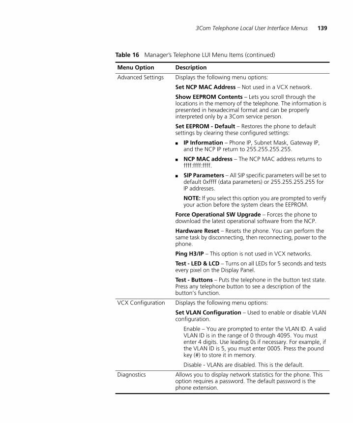
3Com Telephone Local User Interface Menus 139
Advanced Settings Displays the following menu options:
Set NCP MAC Address – Not used in a VCX network.
Show EEPROM Contents – Lets you scroll through the locations in the memory of the telephone. The information is presented in hexadecimal format and can be properly interpreted only by a 3Com service person.
Set EEPROM - Default – Restores the phone to default settings by clearing these configured settings:
■ IP Information – Phone IP, Subnet Mask, Gateway IP, and the NCP IP return to 255.255.255.255.
■ NCP MAC address – The NCP MAC address returns to ffff:ffff:ffff.
■ SIP Parameters – All SIP specific parameters will be set to default 0xffff (data parameters) or 255.255.255.255 for IP addresses.
NOTE: If you select this option you are prompted to verify your action before the system clears the EEPROM.
Force Operational SW Upgrade – Forces the phone to download the latest operational software from the NCP.
Hardware Reset – Resets the phone. You can perform the same task by disconnecting, then reconnecting, power to the phone.
Ping H3/IP – This option is not used in VCX networks.
Test - LED & LCD – Turns on all LEDs for 5 seconds and tests every pixel on the Display Panel.
Test - Buttons – Puts the telephone in the button test state. Press any telephone button to see a description of the button’s function.
VCX Configuration Displays the following menu options:
Set VLAN Configuration – Used to enable or disable VLAN configuration.
Enable – You are prompted to enter the VLAN ID. A valid VLAN ID is in the range of 0 through 4095. You must enter 4 digits. Use leading 0s if necessary. For example, if the VLAN ID is 5, you must enter 0005. Press the pound key (#) to store it in memory.
Disable - VLANs are disabled. This is the default.
Diagnostics Allows you to display network statistics for the phone. This option requires a password. The default password is the phone extension.
Table 16 Manager’s Telephone LUI Menu Items (continued)
Menu Option Description

140 CHAPTER 8: CONFIGURING TELEPHONE COMMUNICATION SETTINGS
9
CONFIGURING TELEPHONE FEATURES FOR A USERThis chapter describes the telephone features available to individual phones in your VCX system.
This chapter includes the following topics:
■ Configuring Phone Features
■ Configuring ToS Phone Features
■ Configuring Features Mapped to Telephone Buttons
■ Blocking Anonymous Callers
■ Configuring Phone Call Restrictions
■ Configuring Call Coverage for a Telephone
■ Configuring Selective Ringing
■ Configuring Bridged Extensions
■ Mapping Bridged Extensions
Be sure to set your Web browser preferences so that the cache is updated whenever you modify or view a new web page.

142 CHAPTER 9: CONFIGURING TELEPHONE FEATURES FOR A USER
Configuring Phone Features
Some features available for a telephone are determined by the Type of Service (ToS) enabled for the phone (see Configuring Type of Service). Other features are provided by default. Many features, however, require configuration. For example, the Call Forward Busy feature must be configured with the extension to which calls will be forwarded when the phone user is on another call.
Phone feature configuration can be performed by you, the administrator, or by the phone user (using the TUI or VCX User web interface). This chapter describes administrator configuration of phone features.
To see the features available on a phone:
1 Access the office location of the user whose phone features you want to configure (see Accessing a VCX Site through the Central Manager).
2 Select Users Menu > Users > Users.
The Users page appears.
The procedure describes how to configure features for a phone extension that has been assigned to a user. You can also configure features for a phone extension that has not been assigned to a user. To do this, select Users Menu > Phones > Phones.
3 Locate the user whose phone features you want to configure.
4 In the Phones column, click the Phones link.
The User - Assigned Phones page appears for the selected user. See Figure 25.

Configuring Phone Features 143
Figure 25 User - Assigned Phones Page
The Action column provides links to the following phone feature configuration options:
■ Features — Clicking this link allows you to configure the following features (provided by the enabled ToS and described in Table 9):
■ Call Forward Busy — See Call Forward.
■ Call Forward Ring No Answer — See Call Forward.
■ Call Forward Universal — See Call Forward.
■ Caller Identity — See Caller Identity.
■ Speed Dial — See Configuring Personal Speed Dial Numbers.
■ Directed Call Pickup — See Directed Call Pickup.
■ Remote Forward Universal — See Remote Forward Universal.
■ Silent Monitor and Barge In — See Silent Monitor and Barge In.
■ Camp On — Configured for all users. See Configuring Camp On Parameters.
■ Call Coverage — See Configuring Call Coverage for a Telephone.
■ Button Mappings — See Configuring Features Mapped to Telephone Buttons.
■ Call Restrictions — See Configuring Phone Call Restrictions and Blocking Anonymous Callers.
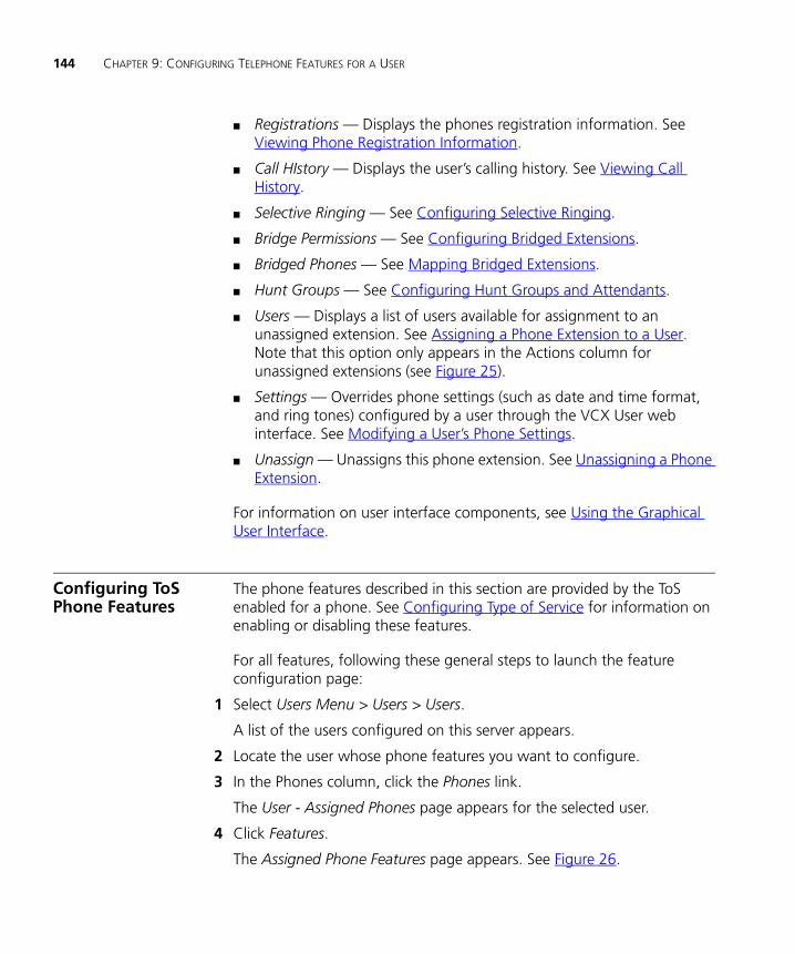
144 CHAPTER 9: CONFIGURING TELEPHONE FEATURES FOR A USER
■ Registrations — Displays the phones registration information. See Viewing Phone Registration Information.
■ Call HIstory — Displays the user’s calling history. See Viewing Call History.
■ Selective Ringing — See Configuring Selective Ringing.
■ Bridge Permissions — See Configuring Bridged Extensions.
■ Bridged Phones — See Mapping Bridged Extensions.
■ Hunt Groups — See Configuring Hunt Groups and Attendants.
■ Users — Displays a list of users available for assignment to an unassigned extension. See Assigning a Phone Extension to a User. Note that this option only appears in the Actions column for unassigned extensions (see Figure 25).
■ Settings — Overrides phone settings (such as date and time format, and ring tones) configured by a user through the VCX User web interface. See Modifying a User’s Phone Settings.
■ Unassign — Unassigns this phone extension. See Unassigning a Phone Extension.
For information on user interface components, see Using the Graphical User Interface.
Configuring ToS Phone Features
The phone features described in this section are provided by the ToS enabled for a phone. See Configuring Type of Service for information on enabling or disabling these features.
For all features, following these general steps to launch the feature configuration page:
1 Select Users Menu > Users > Users.
A list of the users configured on this server appears.
2 Locate the user whose phone features you want to configure.
3 In the Phones column, click the Phones link.
The User - Assigned Phones page appears for the selected user.
4 Click Features.
The Assigned Phone Features page appears. See Figure 26.
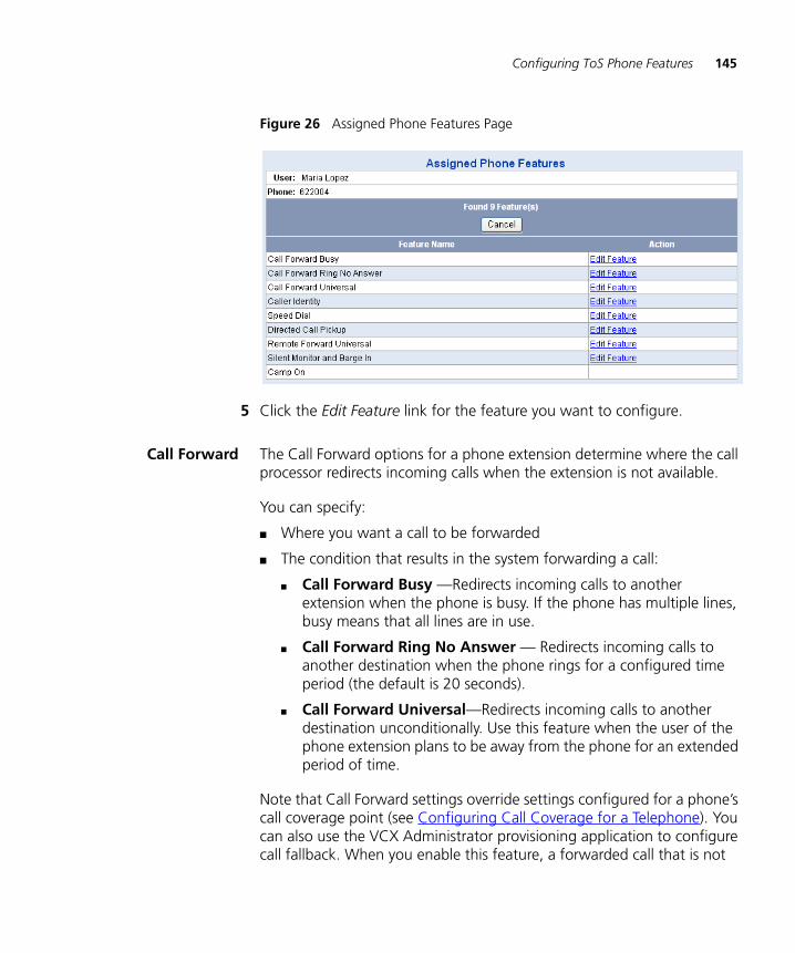
Configuring ToS Phone Features 145
Figure 26 Assigned Phone Features Page
5 Click the Edit Feature link for the feature you want to configure.
Call Forward The Call Forward options for a phone extension determine where the call processor redirects incoming calls when the extension is not available.
You can specify:
■ Where you want a call to be forwarded
■ The condition that results in the system forwarding a call:
■ Call Forward Busy —Redirects incoming calls to another extension when the phone is busy. If the phone has multiple lines, busy means that all lines are in use.
■ Call Forward Ring No Answer — Redirects incoming calls to another destination when the phone rings for a configured time period (the default is 20 seconds).
■ Call Forward Universal—Redirects incoming calls to another destination unconditionally. Use this feature when the user of the phone extension plans to be away from the phone for an extended period of time.
Note that Call Forward settings override settings configured for a phone’s call coverage point (see Configuring Call Coverage for a Telephone). You can also use the VCX Administrator provisioning application to configure call fallback. When you enable this feature, a forwarded call that is not

146 CHAPTER 9: CONFIGURING TELEPHONE FEATURES FOR A USER
answered at the forwarding destination falls back to the original extension's call coverage point if that point is set to voicemail.
To configure a Call Forward option:
1 Follow the steps in Configuring ToS Phone Features to access the Assigned Phone Features page for a user.
2 In the Action column, click Edit Feature in the appropriate Call Forward row.
3 See the online Help for instructions on configuring and enabling a Call Forward option.
Caller Identity By default, the VCX system shows the Caller ID (name and extension) of the calling phone on the Display Panel of the telephone receiving the call if that telephone supports Caller ID. You can control whether the VCX system sends Caller ID information.
To configure the Caller Identity feature:
1 Follow the steps in Configuring ToS Phone Features to access the Assigned Phone Features page for a user.
2 In the Action column, click Edit Feature in the Caller Identity row.
The Caller Identity feature page appears.
3 To enable the feature, ensure a check mark appears in the Blocked box. To disable the feature, remove the check mark.
When enabled, all calls from this phone the Display Panel on the called phone shows “Anonymous” rather than the caller’s name and extension.
4 Click Update.
Configuring PersonalSpeed Dial Numbers
You can configure two types of speed dial numbers, system speed dials and personal speed dials.
■ System speed dial numbers are available to all phone extensions configured in the VCX system. System speed dial configuration is described in Configuring System Speed Dial Numbers.
■ Personal speed dial numbers are configured for a particular extension and are available only to that extension.
You can enter up to nine personal speed dial entries for each user extension. Each speed dial entry is associated with an index number, 1 through 9 inclusive. To use a personal speed dial number, the user

Configuring ToS Phone Features 147
enters Feature code 601 plus the appropriate index number. While you (and users) can also map speed dial numbers to Access buttons on a telephone, the Feature code 601 plus index number method allow speed dialing on phones that do not have Access buttons.
To configure the personal speed dial feature:
1 Follow the steps in Configuring ToS Phone Features to access the Assigned Phone Features page for a user.
2 In the Action column, click Edit Feature in the Speed Dial row.
3 See the online Help for instructions on configuring personal speed dial entries.
Directed Call Pickup The Call Pickup feature allows a user to answer a call that is ringing on another telephone.
There are two types of call pickup:
■ Directed Call Pickup — Allows one user to answer a call ringing on the phone of a second user. Both users must be members of the same Directed Call Pickup group. Each Directed Call Pickup group is assigned a security code. A user must enter this security code when using Directed Call Pickup to answer a call.
■ Group Call Pickup — Allows a user to answer a call ringing on the phone of any user who is a member of a configured Group Call Pickup group. No security code is required. Group Call Pickup configuration is described in Configuring Call Pickup Groups.
To configure the Directed Call Pickup feature:
1 Follow the steps in Configuring ToS Phone Features to access the Assigned Phone Features page for a user.
2 In the Action column, click Edit Feature in the Directed Call Pickup row.
3 See the online Help for instructions on configuring and enabling a Directed Call Pickup group.
Remote ForwardUniversal
The Remote Forward Universal feature allows a user to configure the forwarding options of a telephone from another telephone in the network. The Remote Forward Universal feature is useful if, for example, a person A (at extension 1000) is on vacation and all of person A’s calls must be forwarded to person B (at extension 1001). This feature enables person B to configure Call Forward Universal on the source phone (person

148 CHAPTER 9: CONFIGURING TELEPHONE FEATURES FOR A USER
A). Note that person A can be at one site and person B can be at a different site.
You must authorize use of the Remote Forward Universal feature for the extension whose calls will be forwarded. In this example, you would enable the Remote Forward Universal feature on extension 1000 and specify that extension 1001 is allowed to forward calls to extension 1000. Extension 1001 then uses Feature Code 468 to specify the destination extension for calls to extension 1000.
When enabled, the LED (if available) on extension 1000 flashes for all forwarded calls, and the LCD displays a call forward message.
To configure the Remote Forward Universal feature:
1 Follow the steps in Configuring ToS Phone Features to access the Assigned Phone Features page for the extension whose calls you to forward (extension 1000 in the example).
2 In the Actions column, click Edit Feature in the Remote Forward Universal row.
3 See the online Help for instructions on configuring and enabling the Remote Forward Universal feature.
Silent Monitor andBarge In
The Silent Monitor and Barge In feature is enabled on the phone of an agent. Calls to the agent can be monitored by a supervisor who can also participate in (barge in) to a monitored call.
To configure the Silent Monitor and Barge In feature:
1 Follow the steps in Configuring ToS Phone Features to access the Assigned Phone Features page for the user whose phone will be monitored.
2 In the Actions column, click Edit Feature in the Silent Monitor and Barge In row.
3 See the online Help for instructions on configuring and enabling the Silent Monitor and Barge In feature.
Configuring Features Mapped to Telephone Buttons 149
Configuring Features Mapped to Telephone Buttons
VCX software maps calling features to buttons on VCX telephones. For example, many phones have a button users press to transfer a call to another destination. Mapping a feature to a button allows one-touch access to that feature.
Every VCX phone has a set of default features mapped to buttons. For the 3Com Business telephones (Models 3102 and 2102) and Manager’s telephone (Model 3103), a button mapping template determines what features are available for a particular phone model (see Using Button Mapping Templates). The template available for each phone model is determined by the Type of Service (ToS) assigned to the enabled phone profile.
Unless locked by the template, you can change the features mapped to telephone buttons for individual extensions. For example, you can enable a button on a user’s phone as a bridged line and map the button to the extension of the primary (bridged) phone.
To map features to buttons on a user’s telephone:
1 Select Users Menu > Users > Users.
A list of the users configured on this server appears.
2 Locate the user whose phone buttons you want to configure.
3 In the Phones column, click the Phones link.
The User - Assigned Phones page appears for the selected user.
4 Click Button Mappings.
The Button Mappings page appears.
5 See the online Help for instructions on mapping features to telephone buttons.
Blocking Anonymous Callers
You can block all incoming calls to an extension that arrive from anonymous sources. With this feature incoming calls with Identification Protection are blocked—the caller must allow his or her number to be identified to communicate with the called phone.
To block anonymous calls to an extension:
1 Select Users Menu > Users > Users.
The Users page appears.
150 CHAPTER 9: CONFIGURING TELEPHONE FEATURES FOR A USER
2 Click Phones in the Phones column.
The User - Assigned Phones page appears.
3 Click Call Restrictions in the Actions column.
The Call Restrictions page appears.
4 See the online Help for instructions on blocking anonymous calls.
Configuring Phone Call Restrictions
You can use call restrictions to block specific incoming and outgoing dialing patterns for a phone. These are commonly referred to as blacklists (blocked patterns) and whitelists (allowed patterns). You can configure block and allow lists for both incoming and outgoing calls.
If the incoming or outgoing number matches both the blocked list pattern and the allowed list pattern (for example, 847* is configured for block list and 847262* is configured for allow list), the block list always takes precedence.
The standard format for all dial patterns is <number pattern>*, for example 900*.
The call restrictions feature described in this section allows you to define incoming and outgoing call restrictions for a single phone. Call restrictions may also be configured (as whitelists and blacklists) in the Class of Service (CoS) to which a phone is assigned. If there is a conflict between the calling restrictions defined for the phone and the restrictions defined for a phone's CoS, VCX software applies the restrictions defined in the CoS. See Configuring Class of Service.
You can use the VCX Administrator provisioning application to:
■ Add call restrictions.
■ View current call restrictions.
■ Delete call restrictions.
To add, view, or delete call restrictions for a phone extension:
1 Select Users Menu > Users > Users.
The Users page appears.
2 Click Phones in the Phones column.
The User - Assigned Phones page appears.

Configuring Call Coverage for a Telephone 151
3 Click Call Restrictions in the Actions column.
The Call Restrictions page appears.
4 See the online Help for instructions on managing call restrictions.
Configuring Call Coverage for a Telephone
Incoming calls that are not answered or cannot be answered because the destination is busy or unreachable, follow a specific call coverage pattern. Call coverage determines how a call is routed when a phone is not answered.
Every phone extension has a default coverage point to handle unanswered calls. There are three default call coverage options:
■ Calls can be redirected to the phone’s voice mailbox (this is the default).
■ Calls can be redirected to a telephone number, extension, or auto attendant.
■ Calls are not redirected. The caller hears a busy tone or the phone continues to ring until the caller hangs up.
If Call Fallback is enabled for the extension, voice mail is the only valid call coverage option. Call Fallback is enabled in the phone profile assigned to a group of phones. Call Fallback can also be set for individual phones on the User Phone Settings page (see Modifying a User’s Phone Settings).
The combination of call coverage to voicemail and Call Fallback works as follows:
A call to extension A gets forwarded to extension B if extension A is busy. Extension A has also enabled the Fall Back option. Extension A receives a call that gets forwarded to extension B. However, extension B is also busy. Instead of sending the call to extension B's coverage point or call forwarding destination, VCX returns the call to extension A's voice mail.
In addition to the default call coverage point, you can create a coverage plan for a phone extension. A coverage plan consists of coverage rules. A rule specifies the call coverage point (voice mailbox or number) to which unanswered calls should be redirected based on a specific date, day of the week, or time. For example, you can configure a coverage rule that specifies unanswered calls on weekdays be forwarded to one extension
152 CHAPTER 9: CONFIGURING TELEPHONE FEATURES FOR A USER
and unanswered calls on weekends be redirected to another telephone number.
The following types of scheduled coverage rules are available (listed in order of priority):
■ One-time events
You can configure a rule for a one-time event that lasts for a single day, multiple days, or part of a day.
■ Repeating events
You can configure a rule for events that repeat on a weekly basis. These events span one day or less.
■ Default coverage
You can assign multiple coverage rules to a phone extension, each rule covering a different time window (event). However, one-time and repeating events cannot overlap.
Changing the DefaultCall Coverage Point
for a Phone
When you create a phone extension and associated voice mailbox, VCX software automatically assigns the extension’s voice mailbox as the default coverage point. You can change the default call coverage point to a telephone number (or extension) to which unanswered calls to the extension should be redirected. Alternatively, you can set the default to no coverage.
To change the default call coverage for a phone extension:
1 Select Users Menu > Users > Users.
A list of the users configured on this server appears.
2 Locate the user whose phone features you want to configure.
3 In the Phones column, click the Phones link.
The User - Assigned Phones page appears for the selected user.
4 In the Actions column, click Call Coverage.
5 See the online Help for instructions on changing the default call coverage point.
Configuring Call Coverage for a Telephone 153
Adding a CallCoverage Rule for a
Telephone Extension
When you create a phone extension and associated voice mailbox, VCX software automatically assigns the voice mailbox as the default coverage point. In addition to the default coverage point, you can create a call coverage plan for the extension.
As described in Configuring Call Coverage for a Telephone, a call coverage plan consists of coverage rules. Each rule is based on a date, day, or time event.
You have two options when assigning a call coverage rule to an extension:
■ You can assign a predefined coverage rule. See Adding a Predefined Call Coverage Rule for an Extension.
This option allows you to select coverage settings previously configured through options on the DIRECTORY interface and are available to all phone extensions configured on this server. These options are described in Chapter 13 and include:
■ Coverage rules based on a holiday — See Managing Holidays.
■ Coverage rules based on the day of the week — See Managing Week Day Bands.
■ Coverage rules based on a time range— See Managing Day Time Bands.
■ Coverage rules based on a date or date range — See Managing Calendar Bands.
■ You can create a call coverage rule for this phone extension. A rule created for an individual extension is, by default, not available to other extensions. See Creating a Call Coverage Rule for an Extension.
Adding a Predefined Call Coverage Rule for an Extension
To add a predefined call coverage rule for a phone extension:
1 Select Users Menu > Users > Users.
A list of the users configured on this server appears.
2 Locate the user whose phone features you want to configure.
3 In the Phones column, click the Phones link.
The User - Assigned Phones page appears for the selected user.
4 In the Actions column, click Call Coverage.

154 CHAPTER 9: CONFIGURING TELEPHONE FEATURES FOR A USER
5 See the online Help for instructions on adding a predefined call coverage rule.
New rules are assigned to the phone extension and take effect immediately.
You cannot edit a predefined rule (for example, to adjust the time). You must delete the rule and either assign a different predefined rule or create a rule for the extension with the correct settings.
Creating a Call Coverage Rule for an Extension
To create a call coverage rule for a phone extension:
1 Select Users Menu > Users > Users.
A list of the users configured on this server appears.
2 Locate the user whose phone features you want to configure.
3 In the Phones column, click the Phones link.
The User - Assigned Phones page appears for the selected user.
4 In the Actions column, click Call Coverage.
The Coverage Rules page appears. This page displays the coverage rules in effect for the phone.
5 Click Add Coverage Rule.
6 See the online Help for instructions on creating a call coverage rule.
New rules are assigned to the phone extension and take effect immediately.
Editing a CallCoverage Rule for an
Extension
You can edit a call coverage rule created for an phone extension (for example, to adjust the time). These rules are created and assigned for individual phone extensions through the USERS interface.
Predefined call coverage rules, created through the DIRECTORY interface, can be deassigned from an extension (through the USERS interface) but must be edited through the DIRECTORY interface (see Chapter 13).
To edit a call coverage rule for a phone extension:
1 Select Users Menu > Users > Users.
A list of the users configured on this server appears.

Configuring Selective Ringing 155
2 Locate the user whose phone features you want to configure.
3 In the Phones column, click the Phones link.
The User - Assigned Phones page appears for the selected user.
4 In the Actions column, click Call Coverage.
5 See the online Help for instructions on editing a call coverage rule.
Edited rules take effect immediately.
Deleting a CallCoverage Rule
When you remove a coverage rule for a phone extension, an unanswered call is either redirected by another rule or, if no rule applies, to the default coverage point.
To remove one or more coverage rules from a phone extension:
1 Select Users Menu > Users > Users.
A list of the users configured on this server appears.
2 Locate the user whose phone features you want to configure.
3 In the Phones column, click the Phones link.
The User - Assigned Phones page appears for the selected user.
4 In the Actions column, click Call Coverage.
5 Do one of the following:
■ To remove a single coverage rule, click Delete in the Actions column.
■ To remove a multiple coverage rules, enable the check box preceding the name of each rule and click Delete Selected.
A confirmation box appears verifying you really want to remove these coverage rules from the hunt group.
6 Click OK.
Configuring Selective Ringing
The default ring tone for an incoming call is specified in the phone profile assigned to a phone. See Creating a Phone Profile. You can configure ring tones to identify particular callers or calls to a particular extension. This referred to as selective ringing.
You can configure ring tones to identify calls based on source number. These are calls to an extension from inside callers, outside callers, or

156 CHAPTER 9: CONFIGURING TELEPHONE FEATURES FOR A USER
private callers. You can configure ring tones to identify calls based on destination number (calls to a bridged line or hunt group extension).
Note the following selective ringing considerations:
■ For source-based selective ringing, you can configure distinct ring tones for up to 10 telephone numbers.
■ For destination-based selective ringing, you can configure distinct ring tones for up to 10 bridged line extensions and hunt group extensions combined. Selective ringing for bridged extensions has priority over hunt group extensions.
For example, if you do not configure selective ringing for a bridged extension, you can configure selective ringing for 10 hunt group extensions. If you configure selective ringing for 2 bridged extensions, you can configure selective ringing for 8 hunt group extensions.
If you exceed the selective ringing limit for hunt group extensions, VCX software sorts the extensions by ascending number and implements selective ringing up to the allowed limit. For example, if you configure selective ringing for 2 bridged extensions and 12 hunt group extensions (1001 through 1012), VCX software implements selective ringing for the two bridged extensions and for hunt group extensions 1001 through 1008. Hunt group extensions 1009 through 1012 use the default hunt group ring tone configure in the phone profile.
For each number configured for selective ringing, you can select one of 9 tones and for each tone you can choose to have the telephone ring once, twice, or three times.
To set a selective ring tone for a phone:
1 Select Users Menu > Users > Users.
The Users page appears.
2 Click Phones in the Phones column.
The User - Assigned Phones page appears.
3 Click Selective Ringing in the Actions column for the user’s phone you want to configure.
4 See the online Help for instructions on configuring selective ringing.

Configuring Bridged Extensions 157
Configuring Bridged Extensions
This section describes how to bridge a VCX phone extension.
A bridged phone grants permission for other extensions to receive calls intended for the bridged extension. For example, extension 100 grants bridged permissions to extensions 120 and 121. A call to extension 100 rings on all three extensions (100, 120, and 121). The call can be answered by any of the three extensions. If the call is unanswered, the caller is directed to the call coverage point for extension 100.
The bridged phone is sometimes referred to as the primary phone. The phone receiving bridged calls is sometimes referred to as the secondary phone. A secondary phone must be on the same site as the primary phone.
A VCX Connect system provides telephony services for users in a single site. The primary and secondary extension (or extensions) must be on the same site.
A bridged extension is typically used by an administrative assistant (the secondary phone) to accept calls for up to five managers (primary phones). Or one manager (primary phone) may be monitored by up to five assistants (secondary phones). A call to the primary extension rings on the primary extension and on all secondary extensions.
Optionally, you can enable MWI (Message Waiting Indicator) on a secondary phone. When enabled, the following features are available on the secondary phone:
■ The MWI light on the secondary phone will light when a caller leaves a message at the primary phone and the display panel on the secondary phone shows the number of new and old messages in the voice mailboxes of both the secondary phone and the primary phone.
■ Pressing the MSG button on the secondary phone lists both mailboxes and allows the secondary user to access the voice mailbox of the primary user. Note that the secondary user can access the primary user’s voice mailbox even if the primary user is logged off or the primary phone extension has been disabled.
Bridge permissions can be configured, by a user, through the VCX User web interface or, by the administrator, through the VCX Administrator provisioning application. If bridge permissions are configured for an extension through the Administrator interface, the Bridge Permissions tab

158 CHAPTER 9: CONFIGURING TELEPHONE FEATURES FOR A USER
in the VCX User interface for that extension has preassigned values. However, the user assigned that extension can delete a administrator-assigned bridge permission or assign others.
Bridging is not supported on the Basic phone (Model 3101).
For more information on how bridge permissions work and feature interaction, see the VCX Telephone Guide.
Managing theNumber of Available
Bridged Lines
When you create a phone extension, you assign it to a phone profile. By default, VCX software provides two bridged lines. This allows a primary extension to grant bridging permission to two secondary extensions. It also allows a secondary extension to map two telephone buttons as bridged lines to one or two primary extensions.
You can increase or decrease the number of available bridged lines. The maximum is five bridged lines. The minimum is zero bridged lines.
The number of available bridged lines is controlled by the following two fields:
■ Number of Lines — Determines the number of lines (referred to as System Appearance or SA lines) a phone can use to make or receive calls. This field appears on the Phone Profile page and applies to all extensions assigned to the phone profile (see Creating a Phone Profile).
However, the Number of Lines field also appears on the User Phone Settings page for each extension (see Modifying a User’s Phone Settings). The value specified on this page overrides the global value specified on the Phone Profile page.
The default value is 3 SA lines. The range is from 1 to 9 lines.
■ Number of Bridged Lines — Determines the number lines a phone (either primary or secondary) can use for bridging. The field appears on the User Phone Settings page. The default value is 2 bridged lines. The range is from 0 to 5 lines. As explained below, the number of bridged lines must be at least 1 less than the number of specified SA lines.
Note that, because the Number of Bridged Lines field does not appear on the phone profile page (which applies settings globally), you must set the number of available bridged lines individually for each primary extension on the User Phone Settings page.
Configuring Bridged Extensions 159
How the lines (SA or bridged) are configured on a particular telephone depends on the button mapping template in effect for that phone. Button mapping templates are specified in a Type of Service (see Configuring Type of Service), and ToS is specified in a Phone Profile. VCX software includes two button mapping templates for the following 3Com telephones: Model 2102, Model 3102, and Model 3103.
By default, the button mapping templates for Model 2102 and Model 3102 telephones map 3 buttons as SA lines. No buttons are mapped as bridged lines.
The Model 3103 telephone also has 3 SA lines available but does not map buttons to those lines. No buttons are mapped as bridged lines.
Ensure that each phone model has enough SA lines to support the number of primary bridged lines you want to configure. For example, if you want a phone extension to have five primary bridged lines, verify that:
■ For all phone models (2102, 3102, 3103), ensure that the User Phone Settings page for the extension has the Number of Lines field set to six or more.
■ For the Model 2102 and Model 3102 telephones ensure that the button mappings in effect for the phone extension have at least six SA lines mapped.
The number of bridged lines must be at least 1 less than the number of specified SA lines because a primary phone must have at least one SA line available to receive hunt group calls.
At this point, the SA lines on the primary phone are still not considered primary bridged lines because the primary has not granted bridge permission to any secondary extensions. Consequently, a hunt group call rings on the primary’s first SA line.
As soon as bridge permission is granted to the five secondary phone extensions. the first five SA lines on the primary become primary bridged lines. This means that, even if no secondary mapped a line to that primary, a hunt group call would ring on the primary’s sixth SA line.
Note that a button mapping template can control the number of available bridged lines. Each phone extension is associated with three
160 CHAPTER 9: CONFIGURING TELEPHONE FEATURES FOR A USER
templates (through the ToS specified in the phone profile), one for each telephone model. Consider the following examples.
Example 1
■ The phone profile Number of Lines value is 3.
■ The 3102 button mapping template maps 3 SA lines.
■ The 2102 button mapping template maps 2 SA lines.
In this case, the number of primary bridged lines is the lowest number of mapped SA lines minus 1. As the lowest number of mapped SA lines is 2, the number of primary bridged lines is set to 1. You can work around this configuration by changing the Number of Bridged Lines value from 1 to 2 on the User Phone Settings page for the extension using the 3102 button mapping template.
Example 2
■ The phone profile Number of Lines value is 5.
■ The 3102 button mapping template assigned to the extension maps 3 SA lines.
■ The 2102 button mapping template assigned to the extension maps 3 SA lines.
In this case, the number of primary bridged lines is set to 2 (3 mapped SA lines minus 1). However, there are 2 unmapped SA lines available. If you increase the Number of Bridged Lines field for an extension to 3, VCX software automatically tries to map a fourth SA line to a button (to maintain the number of bridged lines = number of mapped SA lines - 1 requirement). If no button can be mapped, the system generates an error message.
Example 3
If you modify a button mapping template so that the number of mapped SA lines is less than or equal to the number of bridged lines, the number of available bridged lines is automatically reset to the number of mapped SA buttons minus 1. For example, if the new button mapping template has only 2 mapped SA buttons, the number of available bridged lines is reduced to 1 if the current value is more than 1.

Configuring Bridged Extensions 161
Note that the current Number of Bridged Lines field value will not change if there is no conflict. If you change to a button mapping template with 1 mapped SA button, the Number of Bridged Lines field value is reduced to 0. If you subsequently change to a template that maps more SA buttons, the Number of Bridged Lines field value is not increased automatically. You must manually update the field value on the User Phone Settings page for individual phone extensions.
Adding BridgePermission for an
Extension
This section describes how to grant bridged permission, on a primary extension, to one or more secondary extensions. You can grant permission for up to five secondary extensions. The actual number of allowed secondary extensions is determined by the number of available System Appearance (SA) lines. See Managing the Number of Available Bridged Lines for more information.
To grant permission for a secondary phone to receive calls to a primary phone:
1 Access the office location of the user whose phone you want to bridge (see Accessing a VCX Site through the Central Manager).
2 Select Users Menu > Users > Users.
A list of the users configured on this server appears.
3 Locate the user assigned to the phone you want to designate as the primary (the phone whose calls you want to allow other phones to receive).
4 In the Phones column, click the Phones link.
The User - Assigned Phones page appears for the selected user.
5 In the Actions column, click Bridge Permissions.
6 See the online Help for instructions on granting bridge permissions for an extension.
The preceding steps identified, on the primary (bridged) extension, the secondary extensions that will be able to answer calls for the primary phone. The next step is to map the primary extension to a button on each secondary phone. See Mapping Bridged Extensions.
162 CHAPTER 9: CONFIGURING TELEPHONE FEATURES FOR A USER
Mapping BridgedExtensions
This section describes how to map a bridged extension (a primary phone) on a secondary phone that has been granted permission to answer calls to a primary phone.
Bridge mapping associates or “maps” a primary extension to a button on the secondary phone. When a call is placed to the primary extension, it also rings on the secondary phone so that it can be answered by either the primary phone user or the secondary phone user.
Mapped bridge extensions can be configured, by a user, through the VCX User web interface or, by the administrator, through the VCX Administrator provisioning application. If a bridged extension is mapped through the Administrator interface, the Button Mappings tab in the VCX User interface for the secondary phone shows the primary extension mapped to a button. However, the secondary user can change the button mapping unless you lock it (see Dynamic Button Mapping Overview).
As described in Managing the Number of Available Bridged Lines, a secondary phone can map up to five buttons to a primary extension. The secondary can, at any time, modify the number of bridged lines mapped to a primary. For example, a phone extension has five primary bridged lines configured and a secondary has five lines mapped to that primary. If an administrator changes the number of bridged lines to four for that primary, no error is reported to the secondary which still has five lines mapped to the primary. The secondary would just never receive a call on the fifth bridged line.
Bridging is not supported on the Basic phone (Model 3101).
To map a primary extension to a button on a secondary phone:
1 Access the office location of the user whose phone you want to configure as a secondary phone (see Accessing a VCX Site through the Central Manager).
2 Select Users Menu > Users > Users.
A list of the users configured on this server appears.
3 Locate the user assigned to the phone you want to designate as the secondary (the phone that will receive calls to the primary phone).
4 In the Phones column, click the Phones link for the secondary phone.
The User - Assigned Phones page appears for the selected user.
5 In the Actions column, click Button Mappings.

Configuring Bridged Extensions 163
6 See the online Help for instructions on mapping a bridged extension on a secondary phone.
You can specify that calls to a bridged extension generate a distinctive ring tone on phones mapped to the bridged extension. The bridged extension (primary phone) rings normally.
■ The ring tone can be specified in the phone profile to which the secondary phone is assigned (see Creating a Phone Profile).
■ The ring tone can be specified for each extension mapped to the bridged extension (see Configuring Selective Ringing).
A ring tone specified for a phone mapped to the bridged extension overrides the ring tone configured in phone profile.

164 CHAPTER 9: CONFIGURING TELEPHONE FEATURES FOR A USER
10
CONFIGURING GLOBAL TELEPHONE FEATURESThis chapter describes how to configure telephone features that apply to all the phones in your VCX system (a region, a region and its branches, or a VCX Connect single-site system).
This chapter includes the following topics:
■ Configuring System Speed Dial Numbers
■ Configuring Camp On Parameters
■ Using Button Mapping Templates
■ Configuring Call Park
Be sure to set your Web browser preferences so that the cache is updated whenever you modify or view a new web page.

166 CHAPTER 10: CONFIGURING GLOBAL TELEPHONE FEATURES
Configuring System Speed Dial Numbers
This section describes how to globally configure speed dial numbers. System speed dial numbers are available to any user at any site in your VCX system.
You can also configure personal speed dial numbers for individual users (see Configuring Personal Speed Dial Numbers). Personal speed dial numbers can be managed by users through the VCX User interface. However, users cannot add, delete, or modify system speed dial numbers.
You create system speed dial numbers through the VCX Administrator provisioning application. System speed dial numbers can be configured for local and remote VCX phone extensions, and for external numbers.
System speed dial numbers are subject to Class of Service restrictions. For example, if a phone is assigned to a CoS that prohibits dialing toll calls, a system speed dial configured for a toll number will not work on that phone.
A user can invoke a system speed dial telephone number using one of the following methods:
■ Access the System Speed Dial Directory through the telephone LCD Display Panel, then press a soft button to dial the selected entry.
■ Enter the system speed dial feature code (700) followed by the index number associated speed dial (1 for the first speed dial number, 2 for the second speed dial number, and so on).
■ Map a dedicated telephone access button to a system speed dial number, which enables one-touch speed dialing.
The server on which you configure system speed dial numbers depends on your VCX system:
■ If your VCX system is configured as a single-site system (for example, a VCX Connect system), access the Central Manager in your web browser by using the IP address of the VCX system.
■ If your VCX system is configured as a multi-site system (regional and branch sites; multiple regional sites; or, multiple, linked VCX Connect systems), access the Central Manager and select the site that was enabled as the system speed dial master site during the initial configuration of VCX software. You cannot manage system speed dials through any other site.
Configuring Camp On Parameters 167
To manage a system speed dial number:
1 From the Central Manager, select the VCX server that has been designated the system speed dial master site (see Accessing a VCX Site through the Central Manager).
2 Select Users Menu > Configurations > System Speed Dials.
3 See the online Help for instructions on adding, modifying, or deleting system speed dial entries.
By default, system speed dial entries are available to users connected to the system speed dial master site, including branch offices. To make the system speed dial entries available to users at other regions in a multi-site system or to users at different VCX Connect sites, you must run the config.sh script. This script is also used to add users to the Global Directory. Log on to each region that will share the system speed dial entries and run the config.sh script as described in Directly Adding a User Directory to the Global Directory.
Configuring Camp On Parameters
This section describes how to configure Camp On parameters. The configured parameter values apply to all Types of Service that include the Camp On feature (see Configuring Type of Service).
Camp On allows a user who places a call to a busy or an unanswered internal telephone to be called back when the called telephone becomes available. When a user activates Camp On, the system monitors the called telephone. When the called telephone becomes available, the system automatically rings the calling party and redials the call.
Camp On can be invoked in either of the following calling conditions:
■ Call Transfer — Allows a user to invoke Camp On while transferring a call to another extension. The calling party waits on hold until the transfer destination becomes available.
■ New Call — Allows a user to invoke Camp On if the called party does not answer. The user enables Camp On and specifies the called party's extension. The user can then hang up or place another call. When the called party becomes available, the system automatically calls the user and then the called party's extension.

168 CHAPTER 10: CONFIGURING GLOBAL TELEPHONE FEATURES
The two Camp On parameters that you can configure apply to the two types of Camp On calls:
■ Camp On Return Interval — Determines how long a transferred caller waits on hold. If the Camp On Return Interval elapses before the transfer destination becomes available, the transferred caller is reconnected with the transferring caller.
The default Camp On Return Interval is 150 seconds (2½ minutes). The range of valid values is 30 to 300 seconds.
■ Camp On Callback Timeout — Determines how long a caller who initiated Camp On waits for a return call from an unavailable destination. If the Camp On Callback Timeout value elapses before automatic callback from the called party occurs, the Camp On operation is canceled.
The default Camp On Callback Timeout value is 1800 seconds (30 minutes). The range of valid values is 300 to 3600 seconds (5 to 60 minutes).
To change the default Camp On Return Interval or Camp On Callback Timeout values:
1 From the Central Manager, select a VCX server (see Accessing a VCX Site through the Central Manager).
2 Select Users Menu > Configurations > Camp On.
3 See the online Help for instructions on modifying Camp On parameters.
Using Button Mapping Templates
3Com maps calling features to buttons on VCX telephones. For example, many phones have a button users press to transfer a call to another destination. Mapping a feature to a button allows one-touch access to that feature.
Every VCX phone has a set of default features mapped to buttons. For the 3Com Business telephones (Models 3102 and 2102) and Manager’s telephone (Model 3103), you can change the default feature-to-button mapping to enable different features. This capability is referred to as dynamic button mapping.

Using Button Mapping Templates 169
Dynamic ButtonMapping Overview
You have the following dynamic button mapping options for the Business and Manager’s telephones:
■ You can specify that all users of a particular phone model use the same button mapping. You enable this option by selecting a button mapping template for a Type of Service (ToS) and assigning that ToS to a phone profile (see Managing Phone Profiles).
VCX software includes, by default, two button mapping templates for each supported phone type. You can, however, create your own template for a phone type, assign it to a ToS, and assign that ToS to a phone profile.
■ You can override the button mappings specified for a phone type in the ToS by mapping buttons for individual users.
You can also allow your users to map buttons to features on their own phones through the VCX User interface. Or, you can prevent users from mapping some or all buttons by locking a feature to a button.
Managing ButtonMapping Templates
The Button Mappings List page displays the configured button mapping templates. You can use this page to create a new template, edit an existing template (including the default templates, or delete a template.
To display the button mapping template list:
1 From the Central Manager, select a VCX server (see Accessing a VCX Site through the Central Manager).
2 Select Users Menu > Services > Button Mapping Templates.
The Button Mapping Templates List page appears. See Figure 27.
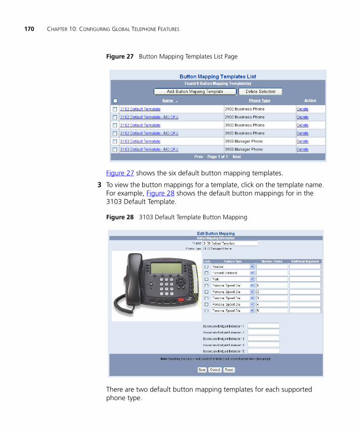
170 CHAPTER 10: CONFIGURING GLOBAL TELEPHONE FEATURES
Figure 27 Button Mapping Templates List Page
Figure 27 shows the six default button mapping templates.
3 To view the button mappings for a template, click on the template name. For example, Figure 28 shows the default button mappings for in the 3103 Default Template.
Figure 28 3103 Default Template Button Mapping
There are two default button mapping templates for each supported phone type.

Using Button Mapping Templates 171
For the Model 2102 Business telephone, you can map 12 buttons.
■ 2102 Default Template — Maps one of the 12 buttons to the Call Forward Universal (CFU) function.
■ 2102 Default Template - NO CFU — Omits the CFU mapping and maps that button to the Feature function.
VCX Connect does not support the 3Com Model 2102 and 2102-R Business Telephones.
For the Model 3102 Business telephone, you can map 18 buttons.
■ 3102 Default Template — Maps one of the 18 buttons to the Call Forward Universal (CFU) function.
■ 3102 Default Template - NO CFU — Omits the CFU mapping and maps that button to the Feature function.
For the Model 3103 Manager’s telephone, you can map 8 buttons.
■ 3103 Default Template — Maps one of the 8 buttons to the Call Forward Universal (CFU) function.
■ 3103 Default Template - NO CFU — Omits the CFU mapping and maps that button to the Feature function.
Creating a Button Mapping Template
If the button mapping in any of the default templates does not suit your needs, you can either modify the default template (see Modifying a Button Mapping Template) or create your own template.
See Mapping System Appearance Lines for considerations when mapping System Appearance lines or bridged lines.
To create a button mapping template:
1 From the Central Manager, select a VCX server (see Accessing a VCX Site through the Central Manager).
2 Select Users Menu > Services > Button Mapping Templates.
The Button Mappings List page appears.
3 Click Add Button Mapping.
The Add Button Mapping page appears.
4 See the online Help for instructions on creating a button mapping template.

172 CHAPTER 10: CONFIGURING GLOBAL TELEPHONE FEATURES
Mapping System Appearance Lines
Button mapping System Appearance (SA) lines requires special consideration. SA lines determine the number lines a phone can use to make or receive calls.
On Model 2102 and 3102 phones, you can map a maximum of 9 buttons as System Appearance lines. You can map any button as an SA line. You cannot map System Appearance lines on the Model 3103 phone.
While a Model 2102 and 3102 button mapping template can map 9 buttons as SA lines, the actual number of lines available for an extension is determined by the value specified in the Number of Lines field. This field appears on the Phone Profile page and the User Phone Settings page.
When you create a phone profile and assign it to an extension, the value specified in the Number of Lines field is the same on both the Phone Profile page and the User Phone Settings page. If you modify the Number of Lines field on the User Phone Settings page, that value overrides the value specified in the phone profile.
If the number of mapped System Appearance lines in a button mapping template exceeds the number of lines specified in the phone profile or on the User Phone Settings page, VCX software will generate an error when you try to save the template.
Bridged lines also require special consideration. A bridged (primary) extension grants permission to other (secondary) extensions to answer calls made to the bridged extension. The number of lines an extension can use for bridging is specified in the Number of Bridged Lines field on the User Phone Settings page.
For a Model 2102, 3102, or 3103 button mapping template, you can map up to 5 buttons to the Secondary Bridged Extension feature. However, you must have sufficient SA lines available (but not necessarily mapped). See Managing the Number of Available Bridged Lines.

Using Button Mapping Templates 173
Deleting a Button Mapping Template
You can delete any existing button mapping template except the VCX-supplied default templates. However, you cannot delete a template that is linked to a ToS. See Configuring Type of Service for information on removing a button mapping template from a ToS.
1 From the Central Manager, select a VCX server (see Accessing a VCX Site through the Central Manager).
2 Select Users Menu > Services > Button Mapping Templates.
The Button Mappings List page appears.
3 In the Actions column of the template you want to remove, click Delete.
A confirmation dialog pops up asking you to confirm you want to delete the selected button mapping template.
4 Click OK.
The template is deleted from the Button Mappings List page.
You can delete multiple templates in one step by enabling the check box next to each template and clicking Delete Selected.
Modifying a Button Mapping Template
You can modify any existing button mapping template, including the VCX-supplied default templates.
You can change a button mappings in a template currently assigned to a set of extensions (through the Type of Service used by the phone profile). Whether of not the changes overwrite the previously configured button mappings depends on the following considerations:
■ A new button mapping that is locked is propagated to all phones using the modified template.
■ A new button mapping that is not locked will be propagated to any phone that has not changed (customized) that button mapping. If the phone has customized a button mapping that conflicts with the modified template, the customized mapping is retained.
When you modify a button mapping template and save it, VCX software checks the mappings for all phones using the template and generates a list of the phone extensions with customized button mappings.

174 CHAPTER 10: CONFIGURING GLOBAL TELEPHONE FEATURES
Consider the following examples. The 3102 Default Template maps button 6 to Do Not Disturb. All phone initially assigned to this template have Do Not Disturb mapped to that button by default.
■ Phone A has not customized button 6. You modify the 3102 Default Template and remap button 6 to Camp On but do not use the Lock option.
Button 6 on Phone A is now mapped to Camp On.
■ Phone A has customized button 6 and mapped it to View Hunt Group. You modify the 3102 Default Template and remap button 6 to Camp On but do not use the Lock option.
Button 6 on Phone A retains the customized View Hunt Group mapping.
■ Phone A has customized button 6 and mapped it to View Hunt Group. You modify the 3102 Default Template and remap button 6 to Camp On and do use the Lock option.
Button 6 on Phone A is now mapped to Camp On. The customized mapping is overridden.
However, these conditions do not apply if you assign a different button mapping template to a set of phone extensions (see Configuring Type of Service). In this case, the button mappings in the new template are applied to all extensions. If a phone has customized button mappings that conflict with the new template, a confirmation message appears. You can choose to cancel the operation (retain the previous template mappings) or proceed with the operation (customized button mappings are overridden by mappings in the new template).
If you want to modify the number of mapped System Appearance lines or the number of bridged lines, see Mapping System Appearance Lines for more information. Any button mapping template change that conflicts with the number of configured lines, bridged lines, and mapped SA lines generates a validation error.
To modify a button mapping template:
1 From the Central Manager, select a VCX server (see Accessing a VCX Site through the Central Manager).
2 Select Users Menu > Services > Button Mapping Templates.
The Button Mappings List page appears.
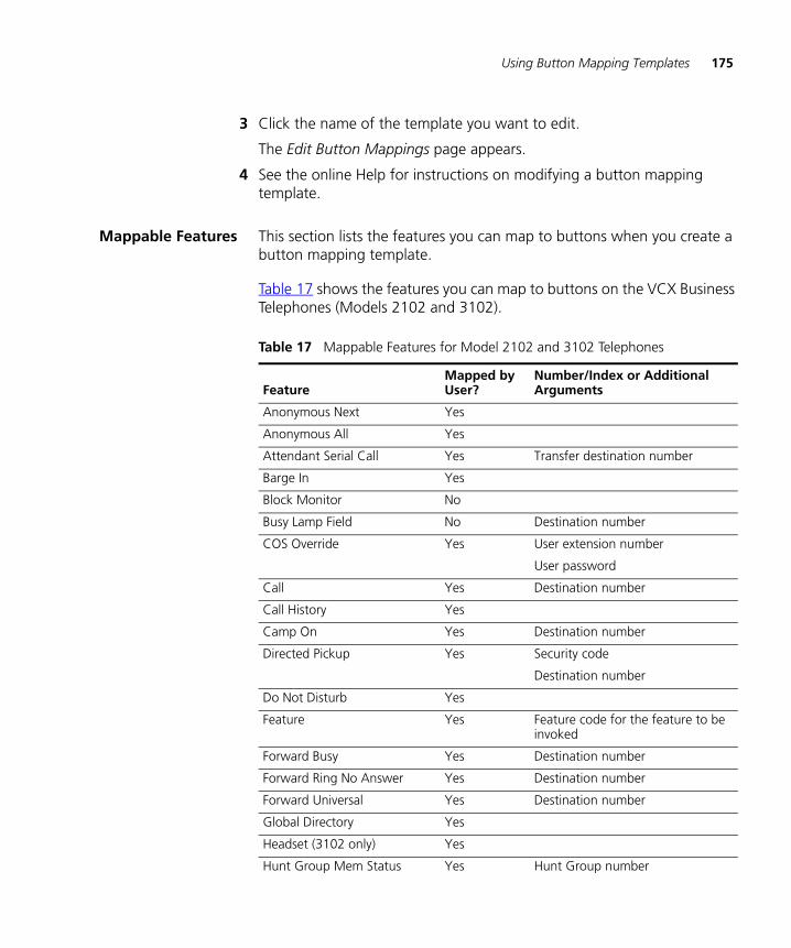
Using Button Mapping Templates 175
3 Click the name of the template you want to edit.
The Edit Button Mappings page appears.
4 See the online Help for instructions on modifying a button mapping template.
Mappable Features This section lists the features you can map to buttons when you create a button mapping template.
Table 17 shows the features you can map to buttons on the VCX Business Telephones (Models 2102 and 3102).
Table 17 Mappable Features for Model 2102 and 3102 Telephones
FeatureMapped by User?
Number/Index or Additional Arguments
Anonymous Next Yes
Anonymous All Yes
Attendant Serial Call Yes Transfer destination number
Barge In Yes
Block Monitor No
Busy Lamp Field No Destination number
COS Override Yes User extension number
User password
Call Yes Destination number
Call History Yes
Camp On Yes Destination number
Directed Pickup Yes Security code
Destination number
Do Not Disturb Yes
Feature Yes Feature code for the feature to be invoked
Forward Busy Yes Destination number
Forward Ring No Answer Yes Destination number
Forward Universal Yes Destination number
Global Directory Yes
Headset (3102 only) Yes
Hunt Group Mem Status Yes Hunt Group number
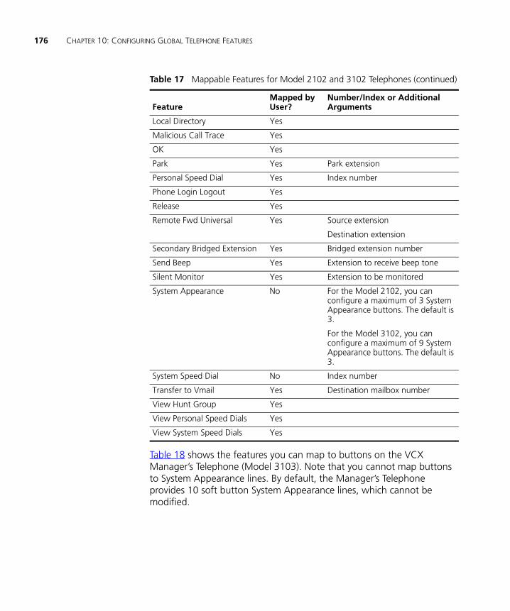
176 CHAPTER 10: CONFIGURING GLOBAL TELEPHONE FEATURES
Table 18 shows the features you can map to buttons on the VCX Manager’s Telephone (Model 3103). Note that you cannot map buttons to System Appearance lines. By default, the Manager’s Telephone provides 10 soft button System Appearance lines, which cannot be modified.
Local Directory Yes
Malicious Call Trace Yes
OK Yes
Park Yes Park extension
Personal Speed Dial Yes Index number
Phone Login Logout Yes
Release Yes
Remote Fwd Universal Yes Source extension
Destination extension
Secondary Bridged Extension Yes Bridged extension number
Send Beep Yes Extension to receive beep tone
Silent Monitor Yes Extension to be monitored
System Appearance No For the Model 2102, you can configure a maximum of 3 System Appearance buttons. The default is 3.
For the Model 3102, you can configure a maximum of 9 System Appearance buttons. The default is 3.
System Speed Dial No Index number
Transfer to Vmail Yes Destination mailbox number
View Hunt Group Yes
View Personal Speed Dials Yes
View System Speed Dials Yes
Table 17 Mappable Features for Model 2102 and 3102 Telephones (continued)
FeatureMapped by User?
Number/Index or Additional Arguments
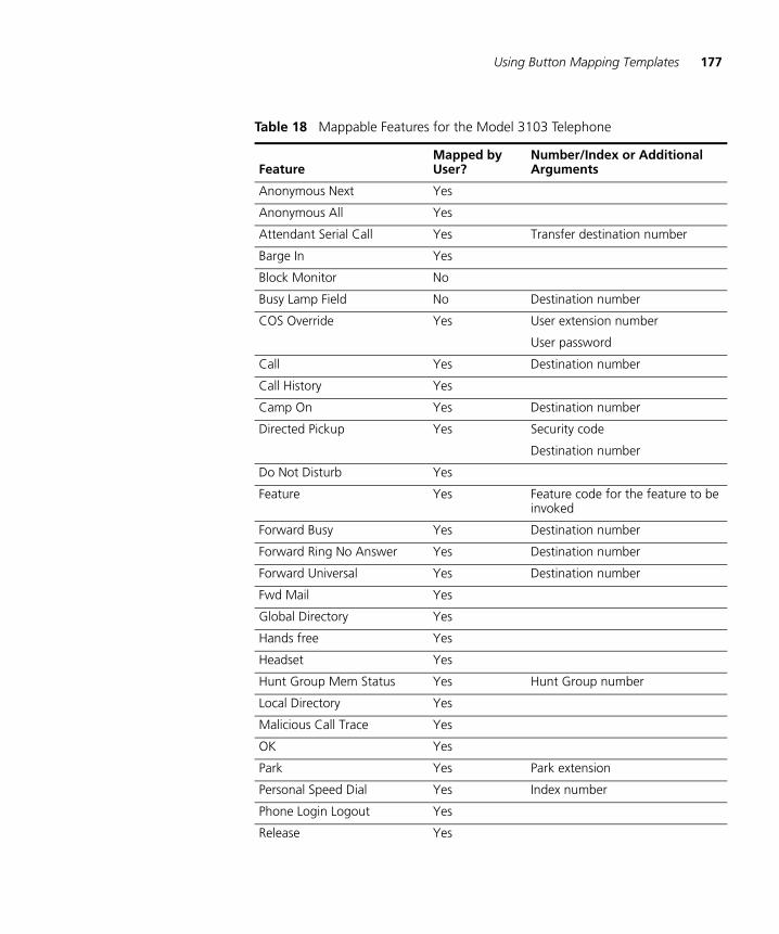
Using Button Mapping Templates 177
Table 18 Mappable Features for the Model 3103 Telephone
FeatureMapped by User?
Number/Index or Additional Arguments
Anonymous Next Yes
Anonymous All Yes
Attendant Serial Call Yes Transfer destination number
Barge In Yes
Block Monitor No
Busy Lamp Field No Destination number
COS Override Yes User extension number
User password
Call Yes Destination number
Call History Yes
Camp On Yes Destination number
Directed Pickup Yes Security code
Destination number
Do Not Disturb Yes
Feature Yes Feature code for the feature to be invoked
Forward Busy Yes Destination number
Forward Ring No Answer Yes Destination number
Forward Universal Yes Destination number
Fwd Mail Yes
Global Directory Yes
Hands free Yes
Headset Yes
Hunt Group Mem Status Yes Hunt Group number
Local Directory Yes
Malicious Call Trace Yes
OK Yes
Park Yes Park extension
Personal Speed Dial Yes Index number
Phone Login Logout Yes
Release Yes

178 CHAPTER 10: CONFIGURING GLOBAL TELEPHONE FEATURES
Configuring Call Park
This section describes how to globally configure call park for a VCX system. Call park allows a user to place a call in a holding pattern where it can retrieved by any user from any telephone on the system.
When a call is parked, it is assigned a call park extension. The call park extension can be explicitly assigned by the user or the user can allow the system to assign the next available call park extension. The parked call can then be retrieved by dialing the call park extension.
The default call park extension numbers are 800 through 899 inclusive, which provides a call park range of 100 numbers. The VCX system allows you configure a call park range with a maximum of 2000 numbers. The length of a call park number can be from 2 digits to 10 digits, inclusive.
VCX software will not allow you to configure a call park range that conflicts with existing extensions (for example, extensions configured for users, groups, or emergency numbers).
When a user parks a call, the VCX system will not allow the user to specify a call park extension that is configured for some other purpose. For example, if the call park extension range overlaps numbers configured for voicemail access, a hunt group, or user extensions, the VCX system will ignore the user-specified call park extension and use the next available, valid call park extension.
Remote Fwd Universal Yes Source extension
Destination extension
Retrieve VMail Yes
Send Beep Yes Extension to receive beep tone
Silent Monitor Yes Extension to be monitored
System Speed Dial No Index number
Transfer to Voicemail Yes Destination mailbox number
View Hunt Group Yes
View Personal Speed Dials Yes
View System Speed Dials Yes
Table 18 Mappable Features for the Model 3103 Telephone (continued)
FeatureMapped by User?
Number/Index or Additional Arguments

Configuring Call Park 179
CAUTION: You must ensure that the dial strings in your selected call park range are allowed by the dial plan in effect on your VCX system. If, for example, you specify a call park range of 4000 through 4099, the dial plan in effect must include a dial rule that allows four-digit dial strings that begin with 4. See Configuring Dial Plans.
By default, a call remains parked for 5 minutes. However, you can adjust this value. If the call is not answered 5 minutes after it is parked, the user who parked the call is called back. If the user is not available, the parked call is forwarded to the user’s call coverage point.
To configure the call park feature:
1 From the Central Manager, select a VCX server (see Accessing a VCX Site through the Central Manager).
2 Select Users Menu > Configurations > Call Park.
3 See the online Help for instructions on managing Call Park extensions.

180 CHAPTER 10: CONFIGURING GLOBAL TELEPHONE FEATURES
11
CONFIGURING GROUPSThis chapter describes how to configure VCX telephone user groups and includes the following topics:
■ Configuring Call Pickup Groups
■ Configuring Page Groups
■ Configuring Hunt Groups and Attendants
■ Using the Group Search Tool
Be sure to set your Web browser preferences so that the cache is updated whenever you modify or view a new web page.

182 CHAPTER 11: CONFIGURING GROUPS
Configuring Call Pickup Groups
A VCX telephone user can use a call pickup feature to answer a call that is ringing on another VCX telephone.
There are two types of call pickup:
■ Directed Call Pickup — Allows a user to answer a call ringing on the phone of a specific user. To answer the call, the user enables the Directed Pickup feature (feature code *455), enters a security code, and then enters the extension of the ringing phone. This transfers the call to the user. See Directed Call Pickup.
■ Group Call Pickup — Allows a user to answer a call ringing on the phone of any user who is a member of a configured Call Pickup group. A Call Pickup group is a collection of phones that allow each member of the group to answer another member's calls if:
■ The other member's telephone is ringing.
■ The other member's telephone has a flashing call appearance light but the call itself is not ringing because the phone has been programmed with Ring Delay or No Ring options.
You can also configure a Call Pickup group to allow non-group members to answer a call ringing on a phone in the group.
Call Pickup configuration requires two general steps: create the group, then add members to the group.
Call Pickup group configuration is subject to the following limits:
■ Each site can support a maximum of 100 groups.
■ Each group can support a maximum of 75 members.
■ An extension can be a member of a maximum of 100 groups.
To create a Call Pickup group:
1 From the Central Manager, select the VCX server on which you want to create the Call Pickup group (see Accessing a VCX Site through the Central Manager).
2 Select Users Menu > Groups > Call Pickup Groups.
The Call Pickup Groups page appears.
3 See the online Help for instructions on configuring a Call Pickup Group.
You can create a maximum of 100 Call Pickup Groups for each site.
Configuring Page Groups 183
Adding Members to aCall Pickup Group
To add members to a Call Pickup Group:
1 From the Central Manager, select the VCX server on which you want to create the Group Call Pickup group (see Accessing a VCX Site through the Central Manager).
2 Select Users Menu > Groups > Call Pickup Groups.
The Call Pickup Groups page appears.
3 Click the Phones link in the Actions column for appropriate group.
4 See the online Help for instructions on adding members to a Call Pickup Group.
Each Call Pickup group can include a maximum of 75 members.
To remove a phone from a group, click Unassign for the appropriate phone number. To delete multiple phones, select them by enabling the check box next to each entry and click Unassign Selected.
Configuring Page Groups
You can configure Page Groups to allow a group member to send a voice audio message to other group members. Member phones must be equipped with a speaker.
Paging is one-way only; page recipients cannot respond to the page.
Depending on how you configure paging on the system, users may be able to send the following types of pages from a member phone:
■ Send a page to a single phone (individual page).
■ Send a page to many phones (group page).
■ Send a page to an external paging amplifier.
■ Send a page to a group and to an external paging amplifier.
Page group members must be local users. A group can include all users at a site or a subset of users.
A telephone can belong to multiple page groups, however a telephone can only receive one page at a time.
When you create a page group, you assign phone extensions as members of the group. You also assign an extension to the page group. When a

184 CHAPTER 11: CONFIGURING GROUPS
group member dials the group page extension, speakers are activated on the telephones that are members of the group. As the member speaks into the handset, the member’s voice is broadcast on the activated speakers. Note that a user does not need to be a member of a page group to send a page to that group.
A page will not be broadcast on a phone if any of the following conditions are true:
■ The phone is not a member of the target page group.
■ The phone is not logged in.
■ The phone is processing a call (that is, the call is ringing, connected, or on hold).
■ The phone has redirect features enabled (Do Not Disturb, Call Forwarding, or Forward to Voicemail).
A page is subject to the following restrictions:
■ Users cannot park, transfer, hold, conference, or pick up a page.
■ Users cannot camp on a page group extension.
■ A page cannot be bridged (see Mapping Bridged Extensions for information about bridging).
A page sender or receiver can drop the page by either using the speaker button to disconnect the page, by picking up and replacing the receiver, or by pressing the Release button.
Page Group configuration is subject to the following limits:
■ Each site can support a maximum of 100 groups.
■ Each group can support a maximum of 300 members.
■ An extension can be a member of a maximum of 100 groups.
Page Group configuration requires two general steps: create the group, then add members to the group.
Creating a PageGroup
To configure a Page Group:
1 From the Central Manager, select a VCX server (see Accessing a VCX Site through the Central Manager).
2 Select Users Menu > Groups > Page Groups.
Configuring Hunt Groups and Attendants 185
3 See the online Help for instructions on configuring a Page Group.
You can create a maximum of 100 Page Groups for each site.
Adding Members to aPage Group
To add members to a Page Group:
1 From the Central Manager, select a VCX server (see Accessing a VCX Site through the Central Manager).
2 Select Users Menu > Groups > Page Groups.
3 On the Page Groups page, click on the Phones link in the Actions column for the appropriate group.
4 See the online Help for instructions on adding members to a Page Group.
Each Page Group can include a maximum of 300 members.
Configuring Hunt Groups and Attendants
You can establish formal and informal call centers so that incoming calls can be directed to several telephones that have been associated into hunt groups or attendant coverage.
A call center is a general term that refers to any system that accepts incoming calls to a site, ensures that those calls are sent to the proper destination within the site, and manages database records on call activity and distribution. The call center can be used, for example, as a help desk, a reservations counter, an information hotline, or a customer service center.
Hunt Groups andCalling Groups
A hunt group is a group of VCX phone extensions that are configured to share a virtual extension. An incoming call to the virtual extension rings on the phone of one hunt group member. If that member’s telephone is in use, or if that member does not answer the call, the system “hunts” for another member of the group until the call is answered or is forwarded to the group call coverage point. For example, if there are no available members of the hunt group, the call might be forwarded to a group mailbox or to the receptionist.
You can configure a hunt group in which all members are fax machines. Incoming faxes are routed to an available fax machine. Depending on the type of hunt group configured, if no fax machine is available, pending faxes may be queued until a machine becomes available or they may be sent to the call coverage point.

186 CHAPTER 11: CONFIGURING GROUPS
The method used to hunt for an available hunt group member is determined by a configured call ring pattern for that group. Pattern types include linear, circular, and calling groups. These patterns are described in the section, Hunt Group Types.
Hunt Group Types
The type of hunt group determines how incoming calls are allocated to group members. You can configure a linear hunt group, a circular hunt group, and a calling group.
To illustrate the differences between hunt group types, assume you have configured four members (A, B, C, and D) for each type. Note that a member must be logged in to both the VCX system and the group to receive a call.
■ Linear Hunt Group — An incoming call always rings at the first member phone of the group, then, if the call is not answered, at the phone of the next member in the group list.
For example, if A, B, C, and D are all logged in, an incoming call will always ring first at member A’s extension. If A does not answer, the call is routed to member B’s extension, and so on until the last member of the group is reached. If no member is logged in, the call is routed to the call coverage point immediately. When the total timeout value configured for the group is reached or the last hunt group member fails to answer (whichever happens first), the call is routed to the call coverage point (see the discussion of timeout values and call coverage points later in this section).
■ Circular Hunt Group — An incoming call rings at the member phone following the member to whom the last call was routed. If the call is not answered, the call rings at the phone of the next member in the group list.
For example, if A, B, C, and D are all logged in and member B received that last call, the next call will ring at member C’s extension. If C does not answer, the call is routed to member D’s extension, and so on until the total timeout value for the group is reached (see the discussion of timeout values later in this section).
■ Calling Group — An incoming call rings simultaneously on all member phones that are logged in, even if a member is on another call.
For example, if A, B, C, and D are all available, an incoming call will ring simultaneously at all four extensions until the total timeout value

Configuring Hunt Groups and Attendants 187
for the group is reached (see the discussion of timeout values later in this section).
For each hunt group type, you configure two timeout values:
■ Device Timeout — Specifies how long the VCX call processor rings at one extension before moving to the next extension if there is no answer.
■ Total Timeout — Specifies how long the VCX call processor attempts to make a connection within the group before directing the call to the group’s call coverage point. You can configure the call coverage point to be:
■ A voice mailbox
■ Another group
■ An individual extension
■ An Auto Attendant number
■ An external phone number
Each hunt group has a default call coverage point. However, you can also create a call coverage plan that specifies where unanswered calls should be redirected based on a specific date, day of the week, or time. See Hunt Group and Attendant Call Coverage Options.

188 CHAPTER 11: CONFIGURING GROUPS
Table 19 summarizes how the three group types route incoming calls.
Hunt Group calls routed to a call coverage point always go to the point configured for the Hunt Group, not to the point configured for (or by) the Hunt Group member (that is, the member’s personal call coverage point). If the member has Do Not Disturb enabled, personal (non-Hunt Group) calls go to the call coverage point. However, Hunt Group calls always ring on a member’s phone, regardless of the Do Not Disturb setting.
Attendants In addition to hunt groups, you can use the VCX hunt group configuration menu options to configure attendant call coverage.
An attendant is typically responsible for answering and redirecting calls to a company, division, or department main telephone number. Attendant responsibilities may be handled by one person (for example, a operator or administrative assistant) or by multiple people.
Configuring a HuntGroup or Attendant
This section provides information on how to configure a hunt group or attendant.
When you create a hunt group or attendant, you specify the extension callers dial to access the group or attendant. VCX software automatically creates the extension and an associated voice mailbox.
Table 19 Hunt Group and Calling Group Behavior
ConditionLinear Hunt Group Result
Circular Hunt Group Result
Calling Group Result
No members Go to call coverage. Go to call coverage. Go to call coverage.
All members logged out Go to call coverage. Wait for a member to log in or until total timeout reached.
Go to call coverage.
All members busy Go to call coverage. Wait for a member to become available or until total timeout reached.
Queue the call and wait for an available member or until total timeout reached.
All members available Route call to first member in the list.
Route call to the member following the member to whom the last call was routed.
Ring all member phones.
Total timeout reached Go to call coverage. Go to call coverage. Go to call coverage.
Configuring Hunt Groups and Attendants 189
You need the following IP Messaging information:
■ Voice Mail Number — Identifies the extension dialed by the call processor to access the IP Messaging voicemail system.
■ Announcement Number — Identifies the recording a caller hears before the call is answered (for example, “Your call is important to us. Please hold for the next available agent.”).
■ Music On Hold Number — Identifies the extension dialed by the call processor to play a MOH recording when a caller is put on hold.
When a caller dials a group or attendant number, the call processor connects the call, redirects the caller to the announcement number, and hunts for the next available agent. If no announcement number is configured, the call processor redirects the caller to MOH and hunts for the next available agent. If neither an announcement number or MOH number is configured, the caller hears ringing while the call processor hunts for the next available agent.
You can add users at remote sites (for example, a branch office) to a hunt group or attendant configured on another site (for example, a regional office). To enable a group member at a branch office to access the group’s voice mailbox (or hear MOH or announcements), which is configured on the regional office, you must create a route plan on the branch that identifies the IP Messaging server running at the regional office. See Configuring Routes for Global IP Messaging on a Branch Office.
A VCX Connect system provides telephony services for users in a single site. You cannot create a hunt group or attendant whose members span multiple VCX Connect sites.
If a hunt group contains fax machines, the hunt group can ONLY consist of FAX machines.
Group (hunt group and attendant) configuration is subject to the following limits:
■ Each site can support a maximum of 100 groups.
■ Each group can support a maximum of 75 members.
■ An extension can be a member of a maximum of 25 groups.
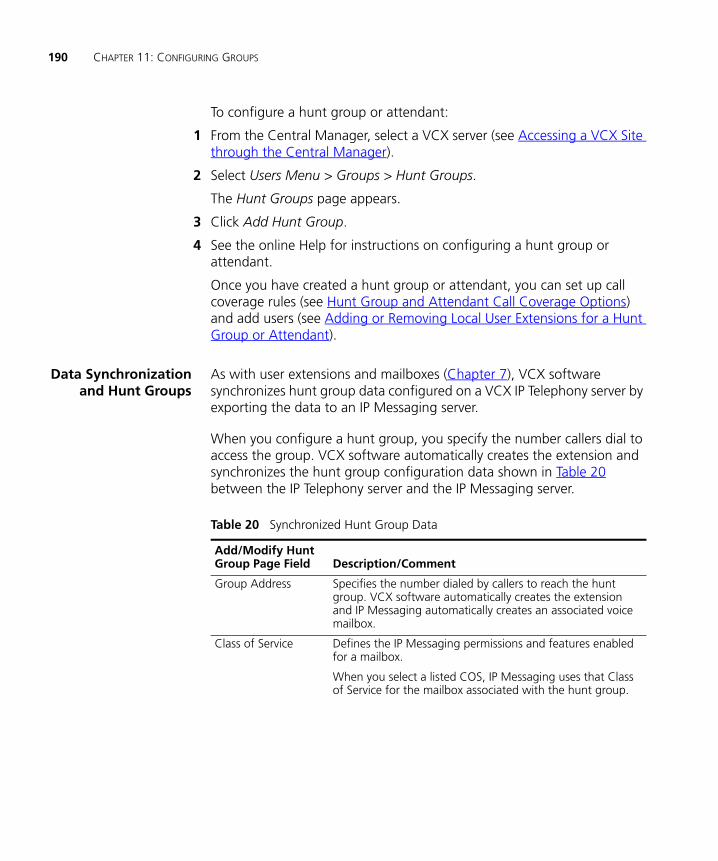
190 CHAPTER 11: CONFIGURING GROUPS
To configure a hunt group or attendant:
1 From the Central Manager, select a VCX server (see Accessing a VCX Site through the Central Manager).
2 Select Users Menu > Groups > Hunt Groups.
The Hunt Groups page appears.
3 Click Add Hunt Group.
4 See the online Help for instructions on configuring a hunt group or attendant.
Once you have created a hunt group or attendant, you can set up call coverage rules (see Hunt Group and Attendant Call Coverage Options) and add users (see Adding or Removing Local User Extensions for a Hunt Group or Attendant).
Data Synchronizationand Hunt Groups
As with user extensions and mailboxes (Chapter 7), VCX software synchronizes hunt group data configured on a VCX IP Telephony server by exporting the data to an IP Messaging server.
When you configure a hunt group, you specify the number callers dial to access the group. VCX software automatically creates the extension and synchronizes the hunt group configuration data shown in Table 20 between the IP Telephony server and the IP Messaging server.
Table 20 Synchronized Hunt Group Data
Add/Modify Hunt Group Page Field Description/Comment
Group Address Specifies the number dialed by callers to reach the hunt group. VCX software automatically creates the extension and IP Messaging automatically creates an associated voice mailbox.
Class of Service Defines the IP Messaging permissions and features enabled for a mailbox.
When you select a listed COS, IP Messaging uses that Class of Service for the mailbox associated with the hunt group.

Configuring Hunt Groups and Attendants 191
Automatic mailbox creation through data synchronization is subject to VCX software license rules introduced in the v8.0 release. You must have sufficient license keys to support the number of phones and mailboxes on your system. See the VCX Maintenance Guide for detailed information.
You cannot use a IP Messaging provisioning interface to modify a voicemail extension or a MOH extension/MOH file association that has been imported from a hunt group configuration. While the interface allows the modification, during the next data synchronization operation, the modification is overwritten with the original value. Similarly, you cannot use a IP Messaging provisioning interface to delete a voicemail extension or a MOH extension that has been imported from a phone profile.
Hunt Group andAttendant Call
Coverage Options
Every hunt group and attendant has a default coverage point to handle unanswered calls. There are two default call coverage options:
■ Calls can be redirected to the hunt group or attendant’s voice mailbox (this is the default).
■ Calls can be redirected to a telephone number or extension.
Music on Hold Number
Specifies the number dialed by the call VCX call processor to access to an audio file configured through the IP Messaging Administration interface. This is the recording (either a voice or music) a caller hears when put on hold.
■ If the number is not already configured on the IP Messaging server, the IP Messaging software creates it.
■ If the number is already configured on the IP Messaging server, the hunt group uses the existing number.
Music on Hold File Identifies the audio file used by the MOH number.
The MOH file field on the Hunt Group page lists all the audio files available for use with the MOH number. You must select an existing file.
Voice Mail Number Specifies the voicemail number the call processor dials to access voicemail services on the IP Messaging server.
■ If the number is not already configured on the IP Messaging server, the IP Messaging software creates it.
■ If the number is already configured on the IP Messaging server, the hunt group uses the existing number.
Table 20 Synchronized Hunt Group Data (continued)
Add/Modify Hunt Group Page Field Description/Comment

192 CHAPTER 11: CONFIGURING GROUPS
In addition to the default call coverage point, you can create a coverage plan for a hunt group or attendant. A coverage plan consists of coverage rules. A rule specifies the call coverage point (voice mailbox or number) to which unanswered calls should be redirected based on a specific date, day of the week, or time. For example, you can configure a coverage rule that specifies unanswered calls on weekends be redirected to another telephone number.
The following types of scheduled coverage rules are available (listed in order of priority):
■ One-time events
You can configure a rule for a one-time event that lasts for a single day, multiple days, or part of a day.
■ Repeating events
You can configure a rule for events that repeat on a weekly basis. These events span one day or less.
■ Default coverage
You can assign multiple coverage rules to a hunt group or attendant, each rule covering a different time window (event). However, one-time events cannot overlap, and repeating events cannot overlap.
In a multi-site VCX environment, hunt group or calling group members can be located in different time zones. Scheduled coverage rules are executed within the time zone provisioned for the hunt group, not according to hunt group member location.
You can enable night service or night attendant coverage by creating a call coverage rule that designates an extension, auto attendant, or voice mailbox as the coverage point during non-business hours.
Changing the Default Call Coverage Point for a Group
When you create a hunt group or attendant, VCX software automatically assigns the group’s voice mailbox as the default coverage point. You can change the default call coverage point to a telephone number or extension to which unanswered calls to the group or attendant should be redirected. Note that you cannot delete the default coverage point.

Configuring Hunt Groups and Attendants 193
To change the default call coverage point:
1 From the Central Manager, select a VCX server (see Accessing a VCX Site through the Central Manager).
2 Select Users Menu > Groups > Hunt Groups.
The Hunt Groups page appears.
3 Click on the Call Coverage link in the Actions column for the appropriate hunt group.
4 See the online Help for instructions on configuring call coverage for a hunt group or attendant.
Adding a Call Coverage Rule for a Group
When you create a hunt group or attendant, VCX software automatically assigns the group’s voice mailbox as the default coverage point. In addition to the default coverage point, you can create a call coverage plan for the group.
As described in Hunt Group and Attendant Call Coverage Options, a call coverage plan consists of coverage rules. Each rule is based on a date, day, or time event.
You have two options when assigning a call coverage rule to a group:
■ You can assign a predefined coverage rule.
This option allows you to select coverage settings previously configured through options on the DIRECTORY interface and are available to all groups and attendants configured on this server. These options are described in Chapter 13 and include:
■ Coverage rules based on a holiday — See Managing Holidays.
■ Coverage rules based on the day of the week — See Managing Week Day Bands.
■ Coverage rules based on a time range— See Managing Day Time Bands.
■ Coverage rules based on a date or date range — See Managing Calendar Bands.
■ You can create a call coverage rule for this group or attendant. A rule created for an individual group or attendant is, by default, not available to other groups or attendants.

194 CHAPTER 11: CONFIGURING GROUPS
Adding a Predefined Call Coverage Rule for a Group
To add a predefined call coverage rule for a group:
1 Access the office location of the group whose call coverage you want to configure (see Accessing a VCX Site through the Central Manager).
2 Select Users Menu > Groups > Hunt Groups.
The Hunt Groups page appears.
3 Click the Call Coverage link in the Actions column for the appropriate hunt group.
4 See the online Help for instructions on adding a predefined call coverage rule for a group.
New rules are assigned to the hunt group or attendant and take effect immediately.
You cannot edit an existing rule (for example, to adjust the time). You must delete the rule and create a new rule with the correct settings.
Creating a Call Coverage Rule for a Group
To create a call coverage rule for a group:
1 Access the office location of the group whose call coverage you want to configure (see Accessing a VCX Site through the Central Manager).
2 Select Users Menu > Groups > Hunt Groups.
The Hunt Groups page appears.
3 Click the Call Coverage link in the Actions column for the appropriate hunt group.
4 See the online Help for instructions on adding a call coverage rule for a group.
The Coverage Rule(s) page reappears and the new rule is listed.
New rules are assigned to the hunt group or attendant and take effect immediately.
You cannot edit an existing rule (for example, to adjust the time). You must delete the rule and create a new rule with the correct settings.

Configuring Hunt Groups and Attendants 195
Deleting a Call Coverage Rule
When you remove a coverage rule for a hunt group or attendant, an unanswered call to the group is either redirected by another rule or, if no rule applies, to the default coverage point.
To remove one or more coverage rules from a hunt group or attendant:
1 From the Central Manager, select a VCX server (see Accessing a VCX Site through the Central Manager).
2 Select Users Menu > Groups > Hunt Groups.
The Hunt Groups page appears.
3 Locate the row for the group whose rule you want to delete and click Call Coverage in the Actions column.
The Coverage Rule(s) page appears listing all currently assigned coverage rules for the group.
4 Do one of the following:
■ To remove a single coverage rule, click Delete in the Actions column.
■ To remove multiple coverage rules, enable the check box preceding the name of each rule and click Delete Selected.
A confirmation box appears verifying you really want to remove these coverage rules from the hunt group.
5 Click OK.
Adding or RemovingLocal User Extensions
for a Hunt Group orAttendant
After creating a hunt group or attendant, you can manage group membership by assigning users to, or removing members from, the group.
Group members can be local or remote (or both) users.
■ Local users have extensions on the same site on which the hunt group or attendant is configured. Adding local users is described in this section.
■ Remote users have extensions on a regional or branch office, which is not the site hosting the hunt group or attendant. Adding remote users is described in Adding or Removing Remote User Extensions for a Hunt Group or Attendant. Note that hunt group and attendant membership for a VCX Connect (single-site) system is restricted to users on that VCX Connect system.

196 CHAPTER 11: CONFIGURING GROUPS
The order in which user extensions are added to a group determines the order in which phones ring within the group (however, you can later rearrange the ringing sequence; see Reconfiguring the Ring Sequence of Group Members). Each hunt group or attendant group can support a maximum of 75 members. The maximum numbers of groups to which an extension can be a member is 25; see Configuring the Message Waiting Indicator for Hunt Group Members for additional information.
To add or remove local user extensions for a hunt group or attendant:
1 From the Central Manager, select a VCX server.
2 Select Users Menu > Groups > Hunt Groups.
The Hunt Groups page appears.
3 See the online Help for instructions on adding a local extension to, or removing a local extension from, a group.
You can specify that calls to a hunt group extension generate a distinctive ring tone on phones assigned to the hunt group.
■ The ring tone can be specified for each extension assigned to the hunt group (see Configuring Selective Ringing).
■ If not specified for an extension, the hunt group ring tone is determined by the phone profile to which the extension is assigned (see Creating a Phone Profile).
A ring tone specified for a hunt group member extension overrides the ring tone configured in phone profile.
Adding or RemovingRemote User
Extensions for a HuntGroup or Attendant
This section describes how to add remote user extensions to, or remove remote user extensions from, a hunt group or attendant. These users have extensions on a regional or branch office, not the site hosting the group. To add local users to a group, see Adding or Removing Local User Extensions for a Hunt Group or Attendant.
A VCX Connect system provides telephony services for users in a single site. You cannot create a hunt group or attendant whose members span multiple VCX Connect sites.
Configuring Hunt Groups and Attendants 197
Adding or removing remote user extensions for a hunt group or attendant is a two step process:
1 On the site hosting the group, add the phone extension of the remote user to (or remove the extension from) the group. Each hunt group or attendant group can support a maximum of 75 members.
2 On the site hosting the user extensions, add the extension to (or remove the extension from) the remote group. The maximum numbers of groups to which an extension can be a member is 25 (see Configuring the Message Waiting Indicator for Hunt Group Members for additional information).
To add or remove a remote user extension for a hunt group or attendant:
1 From the Central Manager, select the VCX server on which the group is configured.
2 Select Users Menu > Groups > Hunt Groups.
3 See the online Help for instructions on adding a remote extension to, or removing a remote extension from, a group.
Next, you must access the site hosting each user extension and add each extension to (or remove the extension from) the remote group.
1 From the Central Manager, select the VCX server on which the phone extension is configured.
2 Select Users Menu > Phones > Phones.
The Phones page appears.
3 Locate the phone extension you want to add or remove for the group.
4 In the Actions column, click Hunt Groups.
5 See the online Help for instructions on adding an extension to, or removing an extension from, a remote group.
198 CHAPTER 11: CONFIGURING GROUPS
Editing or Removinga Hunt Group or
Attendant
You can modify hunt group or attendant attributes established during initial configuration (for example, the group name or class of service). You can also remove a group or attendant no longer in service.
After you delete a hunt group or attendant, you must also delete the associated voice mailbox. Directions for deleting the voice mailbox are located on the Hunt Groups page.
To edit or remove a hunt group or attendant:
1 From the Central Manager, select a VCX server.
2 Select Users Menu > Groups > Hunt Groups.
The Hunt Groups page appears.
3 See the online Help for instructions on editing or removing a hunt group or attendant.
Reconfiguring theRing Sequence of
Group Members
The order in which you add hunt group or attendant member phones determines the initial order in which those phones ring when a call arrives. You can modify the ring sequence by changing a member’s rank within the group.
To modify the ring sequence of a hunt group or attendant:
1 From the Central Manager, select a VCX server.
2 Select Users Menu > Groups > Hunt Groups.
3 See the online Help for instructions on reconfiguring the ring sequence for a hunt group or attendant.
Changing the LoginStatus of Group
Members
Hunt group or attendant members must be logged in to the group to receive calls. Group members can change their login status through the VCX User Interface or the Telephone User Interface (TUI), but you may want to override the current login status, for example, if a hunt group member forgets to log out and leaves the office for the day.
Note the following hunt group and attendant considerations:
■ When a group member initiates a malicious call trace (MCT) on any call, that member is automatically logged out of all groups to which the user belongs. However, the user can still accept direct-dialed internal calls.
Configuring Hunt Groups and Attendants 199
■ If a group member uses attendant serial calling to transfer a call and then logs out of the group, the transferred call returns to another available group member.
To change the log in status of a hunt group or attendant member:
1 From the Central Manager, select a VCX server.
2 Select Users Menu > Groups > Hunt Groups.
The Hunt Groups page appears.
3 Locate the group containing the member whose login status you want to modify and click Status in the Actions column.
The Hunt Group - Status page appears.
4 Locate the member whose login status you want to modify and select the new status (Logged Out or Logged In) in the Status drop down list.
See Configuring the Message Waiting Indicator for Hunt Group Members for information on the Message Waiting Indicator (MWI) field.
5 Click Submit.
The group member’s status is updated.
Configuring theMessage Waiting
Indicator for HuntGroup Members
As described in Configuring a Hunt Group or Attendant, you can specify a call coverage point for a hunt group or attendant. One possible call coverage point is the voicemail account associated with the group extension. If a caller leaves voicemail for the group, you can specify which member phones receive notification of the new voicemail message. Notification is sent by illuminating the Message Waiting Indicator (MWI) light on a phone. You can configure a hunt group or attendant so that some, one, or all members receive notification. Once the message is reviewed, the MWI is extinguished on all phones.
In addition to MWI illumination, a member configured to receive group voicemail notification also sees group mailbox status in the display panel on his or her phone. The member presses the phone’s Message button to display a list of accessible voice mailboxes. The list includes the member’s personal mailbox and any group mailboxes from which the member is configured to receive notification. The member’s extension could also be bridged to a primary extension and therefore have access to the primary extension’s voice mailbox (see Adding Bridge Permission for an Extension).

200 CHAPTER 11: CONFIGURING GROUPS
For example, extension 641001 is a member of two hunt groups, Service and Support, and is configured to receive voicemail notification when a caller leaves voicemail for either group. Extension 641001 is also bridged to the primary extension 641005. When a user presses the Message button on extension 641001, the telephone display panel shows the following information:
■ The number of messages in the personal mailbox for extension 641001.
■ The number of messages in the mailbox for the hunt group Service.
■ The number of messages in the mailbox for the hunt group Support.
■ The number of messages in the mailbox for primary bridged extension 641005.
Note that the display panel can list 26 mailbox status entries. The display panel always lists the mailbox for phone’s extension. Therefore the display panel can list a maximum of 25 status entries for group mailboxes and bridged extension mailboxes. Once the maximum is reached, additional group or bridged extension mailboxes will not be listed.
To change the message waiting indicator of a hunt group or attendant member:
1 From the Central Manager, select a VCX server.
2 Select Users Menu > Groups > Hunt Groups.
The Hunt Groups page appears.
3 Locate the group containing the member whose MWI status you want to modify and click Status in the Actions column.
The Hunt Group - Status page appears.
4 Locate the member whose MWI status you want to modify.
5 In the MWI column, check the MWI status that you want to assign to this hunt group member:
■ Check the box to enable MWI notification for this member.
■ Clear the check box to disable MWI notification for this member
6 Click Submit.
The new configuration is applied to the hunt group or attendant member.
Using the Group Search Tool 201
Using the Group Search Tool
You can search for a any group (hunt, calling, attendant, page, or call pickup) configured on your VCX system. The search results list group information, such as group name and extension, and also all the members of the group.
To search for a group:
1 Select Search Menu.
The User/Groups Search page appears.
2 See the online Help for instructions on entering search criteria to locate one or more groups.

202 CHAPTER 11: CONFIGURING GROUPS

12
CONFIGURING DIAL PLANSThis chapter describes how to use the VCX Administrator provisioning application to manage dial plans, patterns, and dial rules.
This chapter includes the following topics:
■ Configuring Dial Plans
■ Configuring Dial Rules
■ Configuring Patterns
■ Configuring Number Translation
Be sure to set your Web browser preferences so that the cache is updated whenever you modify or view a new web page.
204 CHAPTER 12: CONFIGURING DIAL PLANS
Configuring Dial Plans
Dial plans consist of individual or grouped dial rules. Dial rules determine what sequence of numbers a user is allowed to dial. For example, you can create a dial plan that includes dial rules that allow a user to dial 4-digit extensions starting with 1 or 2. If the user dials less than 4 numbers, more than 4 numbers, or the dial string does not start with a 1 or a 2, the call is not processed.
Your VCX system includes default dial plans and dial rules. However, the Users Menu > Dial Plans menu provides the following options:
■ You can create dial plans that include system-supplied dial rules. See Adding Dial Plans.
■ You can modify an existing dial plan to add or remove dial rules. See Managing Dial Plans.
■ You can create dial rules and add them to an existing dial plan or add them to a new dial plan. See Configuring Dial Rules.
■ You can export a dial plan to a file, copy the file to another VCX system and import the dial plan. You can also modify the rules in the file before importing it. See Exporting Dial Plans.
■ You can import a dial plan.
■ You can import a dial plan file that you have created, modified, or exported.
■ You can import a VCX-supplied dial plan that includes country-specific dial rules.
See Importing Dial Plans.
When you create a dial plan, the dial plan name is added to the Dial Plan drop-down menu on the phone profile configuration page (see Managing Phone Profiles).
Adding Dial Plans To add a dial plan:
1 From the Central Manager, select the VCX server on which you want to add a dial plan.
Verify that the dial rules you want to associate with the new dial plan have been created.
2 Select Users Menu > Dial Plans > Dial Rules.
The Dial Rules page appears listing all the currently configured dial rules.

Configuring Dial Plans 205
■ If the dial rules you want to add to the new dial plan are listed, see the online Help for instructions on adding a dial plan.
■ If the dial rules you want to add to the new dial plan are not listed, see the online Help for instructions on adding a dial rule, then create the dial plan.
Managing Dial Plans You can use the VCX Administrator provisioning application to manage the following dial plan tasks:
■ Edit a dial plan name.
■ Assign additional dial rules to a dial plan or remove existing dial rules assigned to a dial plan.
■ Delete a dial plan. You can delete a dial plan that is no longer in use. You cannot delete a dial plan that is currently assigned to a phone. Deleting a dial plan does not delete the dial rules assigned to that dial plan.
To manage a dial plan:
1 Select Users Menu > Dial Plans > Dial Plans.
The Dial Plans page appears.
2 Select the dial plan you want to manage.
3 See the online Help for instructions for the dial plan management task you want to perform.
Exporting Dial Plans You can export the dial rules in a dial plan to a file.
The file is in CSV (comma separated value) format and the filename is, by default, the name of the selected dial plan.
You can copy the exported file to another VCX system and import the dial plan. You can open the file in any application that accepts the CSV format and modify the rules in the file before importing it. See Importing Dial Plans for import information.
To export a dial plan:
1 Select Users Menu > Dial Plans > Dial Plans.
The Dial Plans page appears.
2 Click Export in the row for the dial plan you want to export.
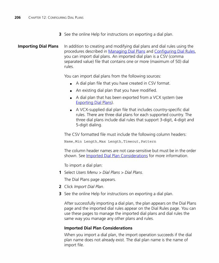
206 CHAPTER 12: CONFIGURING DIAL PLANS
3 See the online Help for instructions on exporting a dial plan.
Importing Dial Plans In addition to creating and modifying dial plans and dial rules using the procedures described in Managing Dial Plans and Configuring Dial Rules, you can import dial plans. An imported dial plan is a CSV (comma separated value) file that contains one or more (maximum of 50) dial rules.
You can import dial plans from the following sources:
■ A dial plan file that you have created in CSV format.
■ An existing dial plan that you have modified.
■ A dial plan that has been exported from a VCX system (see Exporting Dial Plans).
■ A VCX-supplied dial plan file that includes country-specific dial rules. There are three dial plans for each supported country. The three dial plans include dial rules that support 3-digit, 4-digit and 5-digit dialing.
The CSV formatted file must include the following column headers:
Name,Min Length,Max Length,Timeout,Pattern
The column header names are not case-sensitive but must be in the order shown. See Imported Dial Plan Considerations for more information.
To import a dial plan:
1 Select Users Menu > Dial Plans > Dial Plans.
The Dial Plans page appears.
2 Click Import Dial Plan.
3 See the online Help for instructions on exporting a dial plan.
After successfully importing a dial plan, the plan appears on the Dial Plans page and the imported dial rules appear on the Dial Rules page. You can use these pages to manage the imported dial plans and dial rules the same way you manage any other plans and rules.
Imported Dial Plan Considerations
When you import a dial plan, the import operation succeeds if the dial plan name does not already exist. The dial plan name is the name of import file.

Configuring Dial Plans 207
If the dial plan name already exists and you still want to import the file, you must either delete the existing dial plan (see Managing Dial Plans) or rename the import file.
Each imported dial plan CSV file must contain at least one dial rule. The file must include values for the following fields for each dial rule: Name, Min Length (minimum dial string length), Max Length (maximum dial string length), Timeout, and Pattern.
The import operation examines the values for each imported dial rule and compares the values to those for existing dial rules.
Assume that the following dial rule exists in the system:
Test, 10, 10, 5, 1
Given this existing dial rule, Table 21 illustrate the results of various import operations.
Table 21 Dial Rule Import Results
Imported Rule Result
Test, 10, 10, 5, 99 A new rule, Test991010, is created.
The values for the new dial rule Name, Min Length, and Max Length fields duplicate the existing rule but the Pattern value (99) is different. To create a unique rule Name, the new Pattern value, plus the Min Length and Max Length values, are appended to the Name value to create the new rule.
Test1, 9, 9, 5, 1 A new rule, Test1, created.
The import operation adds a new dial rule because the Min Length and Max Length values do not match the existing dial rule.
Note that if the imported rule was named Test (duplicating the existing rule), a new rule named Test991 would have been created.
Test, 10, 10, 5, 1 No rule is created.
The dial rule already exists. All the values in the imported dial rule are duplicated in the existing dial rule.
Testing, 10, 10, 5, 1 No rule is created.
All the values in the imported dial rule except for Name are duplicated in the existing dial rule. The existing dial rule, Test, is used.

208 CHAPTER 12: CONFIGURING DIAL PLANS
The import operation will fail if the dial plan file includes any of the following errors:
■ The specified filename already exists.
■ The specified filename contains invalid characters (for example: {}, (), [], @ , *, \, :)e.
■ The specified filename exceeds 128 characters.
■ The specified file extension is the wrong file type.
■ The specified file is empty or does not contain a valid dial rule.
■ The specified file contains the wrong number columns, the columns are not in the correct order, or a column value includes an invalid character.
■ The length of dial rule name exceeds 64 characters.
■ The value for the minimum dial string length (Min Length) is greater than the value for the maximum dial string length (Max Length).
■ The value for either Min Length or Max Length is not an integer or the value is not in the range of 0-99.
■ The value forTimeout is not an integer or the value is not in the range of 0-300.
■ The value for Pattern is greater than 31 or the value contains character other than #, * and 0-9.
■ The number of dial rules in the specified file is greater than 50.
■ There is an existing dial rule that contains the same Min Length, Max Length, and Pattern values but the Timeout value is different.
Configuring Dial Rules
Dial rules simplify dialing and are created by configuring patterns for phone numbers or phone number ranges. Dial rules can be grouped to create a dialing plan, which can then be assigned to a phone profile.
You can use the VCX Administrator provisioning application to add and delete dial rules. Note that deleting a dial rule removes it from all dial plans to which the rule is assigned.

Configuring Patterns 209
To manage a dial rule:
1 From the Central Manager, select the VCX server on which you want to add or delete the dial rule.
2 Select Users Menu > Dial Plans > Dial Rules.
3 See the online Help for instructions on adding or deleting a dial rule.
Configuring Patterns
Patterns are used by the VCX call processor to route calls to the correct destination. For example, in a multi-site VCX system, you can create a dial rule for each region that includes a site prefix. You then create a pattern based on the site prefix and create a route plan that associates the pattern with a route to a specific call processor. See Route Plan Configuration Requirements for more information.
If you plan to link multi-site VCX systems or multiple VCX Connect systems through the Global Directory, you must ensure that telephone extensions are unique among the linked systems. One way to do this is by including a site identifier as a prefix to the extensions on each site. For example, you could configure 64100 on one site and 65100 on a second site. The prefix 64 identifies the first site; the prefix 65 identifies the second site. To enable 3-digit dialing within a site, you can set up number translation. See Configuring Number Translation.
You can use the VCX Administrator provisioning application to manage the following pattern tasks:
■ Add a pattern.
■ Edit a pattern.
■ Delete a pattern. A pattern cannot be deleted if it is associated with a route plan. The VCX Administrator application generates an error if you try to delete a pattern that is associated with a route plan.
You can use the VCX Administrator provisioning application to manage patterns through either the Users Menu or the Directory Menu. A pattern configured through one menu appears in the other menu.
To manage a pattern:
1 From the Central Manager, select the VCX server on which you want to add a pattern.
2 Select Users Menu > Dial Plans > Patterns.
210 CHAPTER 12: CONFIGURING DIAL PLANS
The Patterns page appears.
3 See the online Help for instructions for the pattern management task you want to perform.
CAUTION: VCX software provides many default patterns, including patterns for the emergency numbers 911 and 9911. If your country does not use 911 emergency dialing, you must ensure that a dial pattern and dial plan exist for your emergency number, and that the dial plan is included in the phone profile assigned to your users’ extensions. See Configuring Emergency Services for more information.
Configuring Number Translation
The VCX system routes calls by translating numbers based on source and destination calling patterns.
For example, you can set up number translation to facilitate calling between users on the same site. In a multi-site VCX system, you can set up a dialing prefix to identify different sites. Regional office extensions might use the range 771000 through 771099. A branch office might use the range 641000 through 641009. Callers at each site must dial the complete extension to reach a user at the other site. Callers at a site must also dial the full extension to reach a user at the local site unless you configure number translation to drop the site prefix. With number translation configured on each site, a user can dial a four-digit number (10nn) to reach other local users. Note that the dial plan in effect for users must allow a four-digit dial string.
A VCX Connect system provides telephony services for users in a single site and does not support branch sites. You can, however, use the Global Directory to link multiple VCX Connect sites.
You can use the VCX Administrator provisioning application to manage the following number translation tasks:
■ Set up and enable number translation.
■ Edit a number translation pattern.
■ Delete a number translation pattern.
You can use the VCX Administrator provisioning application to manage number translation through either the Users Menu or the Directory Menu. Number translation configured through the Users Menu does not appear on the Directory Menu. Number translation configured through
Configuring Number Translation 211
the Directory Menu allows you to associate number translation with source-based routing. See Configuring Number Translation Patterns.
To manage number translation:
1 From the Central Manager, select the VCX server on which you want to add number translation.
2 Select Users Menu > Dial Plans > Number Translation.
The Number Translations page appears listing all the currently configured translation patterns.
3 See the online Help for instructions for the number translation management task you want to perform.

212 CHAPTER 12: CONFIGURING DIAL PLANS
13
CONFIGURING CALL ROUTE PLANSThis chapter describes how to use the VCX Administrator web interface to manage route plans and advanced call routing features.
This chapter includes the following topics:
■ Accessing the Directory Menu
■ Route Plan Configuration Requirements
■ Configuring Patterns
■ Managing End Points
■ Managing Trusted End Points
■ Managing Routes
■ Managing Route Plans
■ Managing Out Dial Patterns
Be sure to set your Web browser preferences so that the cache is updated whenever you modify or view a new web page.
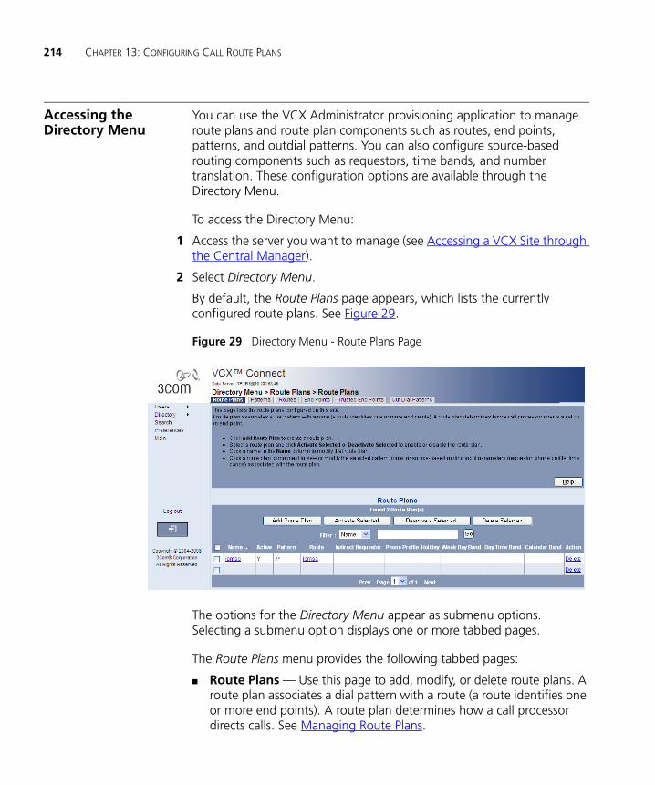
214 CHAPTER 13: CONFIGURING CALL ROUTE PLANS
Accessing the Directory Menu
You can use the VCX Administrator provisioning application to manage route plans and route plan components such as routes, end points, patterns, and outdial patterns. You can also configure source-based routing components such as requestors, time bands, and number translation. These configuration options are available through the Directory Menu.
To access the Directory Menu:
1 Access the server you want to manage (see Accessing a VCX Site through the Central Manager).
2 Select Directory Menu.
By default, the Route Plans page appears, which lists the currently configured route plans. See Figure 29.
Figure 29 Directory Menu - Route Plans Page
The options for the Directory Menu appear as submenu options. Selecting a submenu option displays one or more tabbed pages.
The Route Plans menu provides the following tabbed pages:
■ Route Plans — Use this page to add, modify, or delete route plans. A route plan associates a dial pattern with a route (a route identifies one or more end points). A route plan determines how a call processor directs calls. See Managing Route Plans.
Accessing the Directory Menu 215
■ Patterns — Use this page to manage dial string patterns. Dial string patterns are used by the VCX call processor to route calls to the correct destination. See Configuring Patterns.
■ Routes — Use this page to manage routes. A route includes one or more end points. See Managing Routes.
■ End Points — Use this page to manage end points. An end point, identified by IP address, specifies a device (for example, call processor or gateway) to which calls are routed. See Managing End Points.
■ Trusted End Points — Use this page to configure trusted end points. A trusted end point is a component, such as a conferencing server, that communicates with the VCX call processor. See Managing Trusted End Points.
■ Out Dial Patterns — Use this page to manage Out Dial patterns. An Out Dial pattern is an optional component of an end point and specifies how an outbound destination number is modified. An Out Dial pattern can be used to strip off site-specific access codes. See Managing Out Dial Patterns.
The Route Plan Wizard menu includes a single tabbed page, Route Plan Wizard. The wizard prompts you for the information required to create a route plan. See Using the Route Plan Wizard.
The Advanced menu provides tabbed pages that allow you to manage source-based routing parameters and number translation.
■ Sourced-based routing allows you to control call routing based on the source of a call (an indirect requestor IP address or the members of a phone profile). Routing can be further controlled according to date or time of day. Sourced-based routing tabs include:
■ Requestors — See Managing Requestors.
■ Week Day Bands —See Managing Week Day Bands.
■ Day Time Bands — See Managing Day Time Bands.
■ Calendar Bands — See Managing Calendar Bands.
■ Holiday Bands — See Managing Holidays.
■ Number Translation — Use this page to control call routing by configuring a translation string that matches a destination number. You can further control the translated number by assigning source-based routing parameters (such as date, time, or requestor IP address). See Configuring Number Translation Patterns.

216 CHAPTER 13: CONFIGURING CALL ROUTE PLANS
Route Plan Configuration Requirements
This section describes route plan configuration requirements in a VCX system.
The route plans you need to define depend on your VCX system configuration. As described in VCX Hardware Configurations, a VCX system can be installed on single site or across multiple sites.
A VCX Connect system can be set up on a single server or on a pair of redundant servers. You can link individual VCX Connect systems through the Global Directory to create a multi-site VCX system (see Chapter 3). However, you cannot set up database replication between VCX Connect systems. Also, VCX Connect systems do not support branch sites.
VCX Connect servers are shipped preconfigured (see VCX Connect System Configuration). This preconfiguration includes a default route plan that identifies the IP Messaging server in the VCX Connect system. However, you must configure route plans that identify other end points, such as IP Conferencing servers and media gateways. See Route Configuration to a Gateway for detailed information.
For route plan configuration purposes, you can consider a linked VCX Connect system as a multi-site VCX system without any branch offices.
A route plan associates a dial pattern with a route (a route identifies one or more end points). A route plan determines how a call processor directs calls. End points can be one of the following types:
■ Call Processor — Use this type of call processing end point when a call terminates at the end point (for example, in a single-site system).
■ Redirect Call Processor — Use this type of call processing end point when a call does not terminate at the end point and therefore requires further routing information (for example, a region-to-region call in a multi-site system).
■ Gateway — Use this type of end point to identify IP Messaging servers and clients, IP Conferencing servers, and media gateways (so that calls can be placed throughout the PSTN) end points. See Managing Trusted End Points.
Earlier releases of VCX software required configuration of route plans (called URI route maps in releases prior to VCX software version 7.1) to identify all call processing end points. With version 7.1 and later releases,
Route Plan Configuration Requirements 217
VCX software can create routes between call processors in a VCX single-site or multi-site system using information configured in the Global Directory (see Chapter 3). However, you must configure route plans that identify the IP Messaging servers and clients, IP Conferencing servers, and media gateways in your system. See Route Configuration for Voicemail and Music on Hold and Route Configuration to a Gateway for detailed information.
Although not required, you can still configure route plans to identify call processing end points. See Route Plan Configuration for Single-Site Systems and Route Plan Configuration for Multi-site Systems) for this optional configuration information.
Route PlanConfiguration for
Single-Site Systems
A single-site system includes either a single pair or two pairs of redundant VCX servers.
■ In a single pair system or a VCX Connect system, both servers run the VCX IP Telephony and IP Messaging software configuration. Each server has an IP address for its call processor and IP Messaging module.
■ In a two pair system, one pair of servers runs the call processing software and the second pair runs IP Messaging software. Each server in the first pair has an IP address for its call processor. Each server in the second pair has an IP address for its IP Messaging module.
In both cases, one server in the pair is designated the primary and the other server is designated the secondary.
In a single-site system, you need to configure end points, routes, patterns, and route plans on the primary server running call processing software.
■ You need to create end points that identify the other call processor and the IP Messaging modules.
■ You need to define routes containing the appropriate call processor and IP Messaging end points.
■ You need to define one or more dial string patterns. A pattern identifies the dial string prefix used by an end point. A pattern is associated with a route and indicates which end point should receive a call.
■ You need to create route plans (associate a route with a dial string pattern) on both call processing servers. This enables each call
218 CHAPTER 13: CONFIGURING CALL ROUTE PLANS
processor to route a dialed number to the correct destination (end point).
Example
For example, a VCX single-site system includes two redundant, IP Telephony and IP Messaging VCX servers, A and B. A is the primary server, B is the secondary server.
Note that the following steps reference other topics in this chapter that describe how to configure a route plan and its elements (end points, patterns, and routes). You can also use the Route Plan Wizard to create a route plan and its elements. See Using the Route Plan Wizard.
The following steps configure the required routes on VCX server A.
1 Access the server you want to manage (see Accessing a VCX Site through the Central Manager).
2 Create four end points.
a Add an end point of the type Call Processor that points to A.
b Add an end point of the type Call Processor that points to B.
c Add an end point of the type Gateway that points to the IP Messaging module running on A.
d Add an end point of the type Gateway that points to the IP Messaging module running on B.
For instructions on adding an end point, see Managing End Points.
3 Create two routes.
a Route1 includes the Call Processor end points created for A and B.
b Route2 includes the Gateway end points created for the IP Messaging modules running on A and B.
For instructions on adding routes, see Adding, Editing, or Deleting Routes.
4 Create a pattern for each route.
A pattern is a dial string prefix that indicates which end point should receive a call. You associate a pattern with a route when you create a route plan.
A prefix is created as a dial rule and added to the dial plan in effect for users at the site. For example, the prefix required for a user to call another user could be 4, and the prefix required for a user to access an IP

Route Plan Configuration Requirements 219
Messaging voicemail box could be 5. In this case, you would create two patterns: 4* and 5*.
For instructions on adding a pattern, see Configuring Patterns. For information on dial rules and plans, see Configuring Dial Rules and Configuring Dial Plans.
5 Configure a route plan to associate a pattern and a route.
In this example, you would create a route plan that associates Route1 with the dialing pattern 4*. You would also create a route plan that associates Route2 with the dialing pattern 5*.
For instructions, see Adding a Route Plan.
You do not need to repeat steps 2 through 6 on server B, the secondary server. Data replication between the two servers ensures that the routing information gets propagated to both servers in the redundant pair.
Once you complete these steps, the VCX system can process calls between users, and users can access their IP Messaging voicemail boxes.
Route PlanConfiguration for
Multi-site Systems
In a multi-site system, VCX services run on servers at multiple locations. A multi-site system can include:
■ A regional site with one or more associated branch offices.
■ Multiple regional sites with each region supporting one or more associated branch offices.
■ Multiple regional sites with no associated branch offices.
A VCX Connect system provides telephony services for users in a single site and does not support branch sites.
You need to create end points to identify the call processors at all regional and branch offices, define routes containing the appropriate end points for each region and branch, and create route plans at each site that associate a route with a dial string pattern. This enables the call processor at each site to route a dialed number to the correct destination (end point).
For example, in a VCX multi-site system, a regional office must have routes created to:
■ Itself
■ The other call processor in the redundant pair of VCX servers
220 CHAPTER 13: CONFIGURING CALL ROUTE PLANS
■ Gateways, so that calls can be placed throughout the PSTN
■ Each regional office this call processor wants to communicate with
■ Each branch office hosted by the regional office
■ The IP Messaging server (for Music On Hold and voicemail services) it is associated with
A regional office acts as a redirect call processor for any supported branch offices. Therefore, you need only create a route on each branch office that points to its host regional office (not to other branches or other regions; the branch’s regional host will redirect all calls to other destinations). Each branch also needs a route that points to the IP Messaging server if a local messaging configuration is used (in other words, the branch office is an IP Telephony and IP Messaging configuration that includes a call processor server and an IP Messaging server).
Beginning with VCX version 7.0, you can set up IP Messaging in a client/server configuration. An IP Messaging server can support up to 20 IP Messaging clients. You must define a route on the regional call processor that point to the IP Messaging servers (primary and secondary) and to each client.
The remaining topics in this section describe the route plans you need to create for a multi-site system. Note that these topics reference other topics in this chapter that describe how to configure a route plan and its elements (end points, patterns, and routes). You can also use the Route Plan Wizard to create a route plan and its elements. See Using the Route Plan Wizard.
Configuring Routes Between Regional Offices
If users in one region need to make calls to, and receive calls from, users in another region, you must create routes between all the call processors in both regional offices.
This example describes how to create routes on the primary call processor in one regional office to the other call processors in a multi-site system. The example uses the following simple multi-site system in which the six servers are running IP Telephony and IP Messaging configurations:
■ R1a identifies the primary call processor in region 1.
■ R1b identifies the secondary call processor in region 1.

Route Plan Configuration Requirements 221
■ R2a identifies the primary call processor in region 2.
■ R2b identifies the secondary call processor in region 2.
■ R3a identifies the primary call processor in region 3.
■ R3b identifies the secondary call processor in region 3.
The following steps configure the required routes on the primary VCX server hosting R1a:
1 Access the server you want to manage, in this case R1a (see Accessing a VCX Site through the Central Manager).
2 Create six end points.
a Add an end point of the type Call Processor that points to R1a.
b Add an end point of the type Call Processor that points to R1b.
c Add an end point of the type Call Processor that points to R2a.
d Add an end point of the type Call Processor that points to R2b.
e Add an end point of the type Call Processor that points to R3a.
f Add an end point of the type Call Processor that points to R3b.
For instructions on adding an end point, see Managing End Points.
3 Create three routes.
a Route1 includes the end points created for R1a and R1b.
b Route2 includes the end points created for R2a and R2b.
c Route3 includes the end points created for R3a and R3b
For instructions on adding routes, see Adding, Editing, or Deleting Routes.
4 Create a pattern for each region.
A pattern is a dial string prefix that indicates which regional call processor should receive a call. You associate a pattern with a route when you create a route plan.
You can consider a prefix as a site ID. A prefix is created as a dial rule and added to the dial plan in effect for users at a region. For example, if the site ID on region 1 is 61, the site ID on region 2 is 62, and the site ID on region 3 is 63 you would create these patterns: 61*, 62*, and 63*.
For instructions on adding a pattern, see Configuring Patterns. For information on dial rules and plans, seeConfiguring Dial Rules and Configuring Dial Plans.

222 CHAPTER 13: CONFIGURING CALL ROUTE PLANS
5 Configure a route plan to associate a pattern and a route.
In this example, you would create a route plan that associates Route1 with the dialing pattern 61*, a route plan that associates Route2 with the dialing pattern 62*, and a route plan that associates Route3 with the dialing pattern 63*.
For instructions, see Adding a Route Plan.
You do not need to perform these steps on a secondary server (in this example, R1b). Data replication between the primary and secondary servers ensures that the routing information gets propagated to both servers in the redundant pair.
At this point, you have two options regarding the route configuration on the other regional servers:
■ You could perform steps 2 through 6 on the primary servers hosting R2a and R3a. This would configure all the servers as equals. In this case, each region includes redundant routes to every other region with the end points defined as type Call Processor.
■ Allow only R1a to have all of the routing information for the other regional servers, as configured in steps 2 through 6. In this case, on servers R2a and R3a, you would set up a route that includes end point R1a defined as type Redirect Call Processor.
This option reduces the number of routes you have to configure. If you have a large installation, you could pick one region and have all other servers have one redirect route to that region. Then you would add all of the direct routes to all of the other sites on just that region (R1a, in this example).
For very large installations (multiple regions with many branches), each region could handle the direct routes to branches in that region and have redirect routes for certain patterns to other regions. Consequently, one region would not have to resolve every route.
Note that, if a call can terminate at a region (because there are users configured to use that region’s call processor), you should always configure a route, on the region, to the region itself. For example, R2a could have a route to R1a set up as a Redirect Call Processor type to forward calls to R2a destined for another location. R2a should also have a route to itself set up as a Call Processor type to accept calls to R2a.
Once complete these steps, users can place calls between the regional offices. If you have branch offices, you must configure routes between

Route Plan Configuration Requirements 223
the regional offices and their branch offices. See Configuring Routes on a Branch Office and Configuring a Route from a Regional Office to a Branch Office.
To enable user access to IP Messaging services, see Route Configuration for Voicemail and Music on Hold.
Configuring Routes on a Branch Office
In a multi-site system that includes branch offices, each branch must include a route to its regional call processor. This enables branch users to make calls to destinations outside of the branch, including calls to users at the regional office, at other regional offices, at other branch offices and to users on the PSTN.
Branch office users may also call users on the PSTN through a media gateway located at the branch office (for example, if the branch office has a 3Com V6000 Branch Office Gateway system).
This example describes how to create routes on a branch call processor hosted by region 1. The example uses the following multi-site system:
■ R1a identifies the primary call processor in region 1.
■ R1b identifies the secondary call processor in region 1.
■ R2a identifies the primary call processor in region 2.
■ R2b identifies the secondary call processor in region 2.
■ B1R1 identifies the branch call processor hosted by region 1.
■ B1R1Gw identifies the media gateway at the branch office.
To configure a route from a branch office to its host regional office:
1 Access the server you want to manage, in this case B1R1 (see Accessing a VCX Site through the Central Manager).
2 Create three end points.
a Add an end point of the type Redirect Call Processor that points to R1a.
b Add an end point of the type Redirect Call Processor that points to R1b.
c Add an end point of the type Gateway that points to B1R1Gw.
You do not need to create end points (or a route) for R2a and R2b. Region 1 will redirect calls from B1R1 to the correct destination. This

224 CHAPTER 13: CONFIGURING CALL ROUTE PLANS
assumes, however, that region 1 has a route and route plan configured for region 2.
For instructions on adding an end point, see Managing End Points.
3 Create two routes.
Route1 includes the end points created for R1a and R1b.
Route2 includes the end point created for B1R1Gw.
For instructions on adding routes, see Adding, Editing, or Deleting Routes.
4 Create a pattern for each region a branch user is allowed to call.
A pattern is a dial string prefix that indicates the call destination is inside or outside of the branch office.
You can consider a prefix as a site ID. A prefix is created as a dial rule and added to the dial plan in effect for users at a branch or region. If the site ID for region 1 is 61 and the site ID for region 2 is 62, you would create two patterns: 61* and 62*. You also need to create a pattern that identifies calls to the PSTN, for example, 81*.
For instructions on adding a pattern, see Configuring Patterns. For information on dial rules and plans, see Configuring Dial Rules and Configuring Dial Plans.
5 Configure a route plan to associate a pattern and a route.
In this example, you would create three route plans.
One plan associates Route1 with the pattern 61*.
The second plan associates Route1 with the pattern 62*.
The third plan associates Route2 with the pattern 81*.
For instructions, see Adding a Route Plan.
6 Configure an Out Dial pattern and assign it to an end point associated with a route.
The Out Dial pattern is used to strip off site-specific access codes, which facilitates call routing.
For instructions, see Managing Out Dial Patterns.
Next, create a route on the host regional office to all branch offices located within its region, as described in the next section.

Route Plan Configuration Requirements 225
Configuring a Route from a Regional Office to a Branch Office
In a multi-site system that includes branch offices, a region must include a route to each of its branches. This enables the regional office to route calls to branch users. Do not configure routes directly to any branch offices in a different region. Each region is responsible for routing calls to its branch offices. This minimizes the number of routes that need to be configured and maintained.
This example describes how to create routes on a region that point to its branch offices. The example uses the same simple multi-site system described in Configuring Routes on a Branch Office:
■ R1a identifies the primary call processor in region 1.
■ R1b identifies the secondary call processor in region 1.
■ R2a identifies the primary call processor in region 2.
■ R2b identifies the secondary call processor in region 2.
■ B1R1 identifies one branch call processor hosted by region 1.
To configure a route from a regional office to a branch office:
1 Access the server you want to manage, in this case R1a (see Accessing a VCX Site through the Central Manager).
2 Add an end point of the type Call Processor that points to B1R1.
For instructions on adding an end point, see Managing End Points.
3 Create one route.
BrRoute1 includes the end point B1R1.
For instructions on adding routes, see Adding, Editing, or Deleting Routes.
4 Create a pattern that identifies calls to the branch office.
A pattern is a dial string prefix that indicates the call destination is the branch office.
A prefix is created as a dial rule and added to the dial plan in effect for users at the branch. For example, if the branch prefix is 8, you would create the pattern 8*.
For instructions on adding a pattern, see Configuring Patterns. For information on dial rules and plans, seeConfiguring Dial Rules and Configuring Dial Plans.
5 Configure a route plan to associate a pattern and a route.
226 CHAPTER 13: CONFIGURING CALL ROUTE PLANS
In this example, you would create one route plan that associates BrRoute1 with the pattern 8*.
For instructions, see Adding a Route Plan.
Calls can be now be routed to the branch office from users located outside the branch.
Route Configurationto a Gateway
You need to configure routes from a regional office to a gateway so that call destinations outside of the VCX network can be processed. You may also have to configure routes from a branch office if the branch has its own gateway (for example, the branch office has a 3Com V6000 Integrated Branch Communications system). For branches without a gateway, out of network calls are processed by the branch’s host regional office.
This example describes how to create a gateway route on the primary call processor in one regional office. The example uses the following simple multi-site system in which the six servers are running IP Telephony and IP Messaging configurations:
■ R1a identifies the primary call processor in region 1.
■ R1b identifies the secondary call processor in region 1.
■ R2a identifies the primary call processor in region 2.
■ R2b identifies the secondary call processor in region 2.
■ R3a identifies the primary call processor in region 3.
■ R3b identifies the secondary call processor in region 3.
The following steps configure the required route on the primary VCX server hosting R1a:
1 Access the server you want to manage, in this case R1a (see Accessing a VCX Site through the Central Manager).
2 Create two end points.
a Add an end point of the type Gateway that points to R1a.
b Add an end point of the type Gateway that points to R1b.
For instructions on adding an end point, see Managing End Points.
3 Create one route:
GWRoute1 includes the end points created for R1a and R1b.

Route Plan Configuration Requirements 227
For instructions on adding routes, see Adding, Editing, or Deleting Routes.
4 Create a pattern for the gateway.
A pattern is a dial string prefix that indicates the gateway that should receive a call. You associate a pattern with a route when you create a route plan.
A prefix is created as a dial rule and added to the dial plan in effect for users at a region. For example, if an internal caller must dial 81 plus the number for external calls, you would create the pattern 81*.
For instructions on adding a pattern, see Configuring Patterns. For information on dial rules and plans, see Configuring Dial Rules and Configuring Dial Plans.
5 Configure a route plan to associate the pattern and the route.
In this example, you would create a route plan that associates GWRoute1 with the dialing pattern 81*.
For instructions, see Adding a Route Plan.
You do not need to perform these steps on a secondary server. Data replication between the primary and secondary servers ensures that the routing information gets propagated to both servers in the redundant pair.
Configure any other required routes to gateways by repeating steps 1 through 6.
Whether you need to configure gateway routes on the other regional servers depends on how you have configured those servers relative to R1a.
■ If you have configured R1a to have all of the routing information for the other regional servers (and, therefore, servers R2a and R3a have routes that include the end point R1a defined as type Redirect Call Processor), you do not need to configure a route to the gateway on R2a and R3a.
■ If you have configured R1a, R2a, and R3a as equals (and therefore, each region includes redundant routes to every other region with the end points defined as type Call Processor), you need to repeat steps 2 through 6 on R2a and R3a.
228 CHAPTER 13: CONFIGURING CALL ROUTE PLANS
Route Configurationfor Voicemail and
Music on Hold
If your VCX system uses the IP Messaging system, you need to configure routes to identify the voicemail and Music On Hold (MOH) services.
In a multi-site system, there are three options for configuring routes to provide user access to IP Messaging voicemail and MOH services. The options you select depend on whether your multi-site system includes branch offices and, if it does, where the IP Messaging system is located.
■ When a multi-site system does not include branch offices, IP Messaging services are installed on the redundant VCX servers in each the regional system.
■ When a multi-site system does include branch offices, IP Messaging services can be provided globally or locally.
■ When a multi-site system with branch offices is configured for global messaging, the branch offices include a call processor but no IP Messaging services. In this case, voicemail and MOH services are provided to all branches by the regional server.
■ When a multi-site system with branch offices is configured for local messaging, the branch offices are configured as IP Telephony and IP Messaging systems that include both a call processor and IP Messaging services. In this case, voicemail and MOH services are provided locally by each branch office.
In each of these systems, you can implement IP Messaging in a client/server configuration. An IP Messaging server can support up to 20 IP Messaging clients. One client can be dedicated to non-voice applications such as Web provisioning, e-mail synchronization, and logging. The remaining clients can be dedicated to voice functions. This type of setup improves the IP Messaging server performance.
The topics in this section describe how to configure each option.
Configuring Routes for IP Messaging on a Regional Office
This example describes how to create IP Messaging routes on a regional office. While branch users can use IP Messaging services located on either the branch office or its host region, you must configure IP Messaging routes on each primary regional server for users assigned to that region (that is, users not configured on a branch).
This example describes how to create IP Messaging routes on the primary call processor in a region. The example uses the following simple

Route Plan Configuration Requirements 229
multi-site system in which the six servers are running IP Telephony and IP Messaging configurations:
■ R1a identifies the primary call processor in region 1.
■ R1b identifies the secondary call processor in region 1.
■ IPM1a identifies the primary IP Messaging server in region 1.
■ IPM1b identifies the secondary IP Messaging server in region 1.
■ R2a identifies the primary call processor in region 2.
■ R2b identifies the secondary call processor in region 2.
■ IPM2a identifies the primary IP Messaging server in region 2.
■ IPM2b identifies the secondary IP Messaging server in region 2.
To configure IP Messaging routes:
1 Access the server you want to manage, in this case R1a (see Accessing a VCX Site through the Central Manager).
2 Create two end points.
a Add an end point of the type Gateway that points to IPM1a.
b Add an end point of the type Gateway that points to IPM1b.
For instructions on adding an end point, see Managing End Points.
3 Create one route.
IPMRoute1 includes the end points created for IPM1a and IPM1b.
For instructions on adding routes, see Adding, Editing, or Deleting Routes.
4 Create a pattern for user access to voicemail and MOH.
The access numbers for voicemail and MOH are configured by the IP Messaging system administrator, and are specified when you add a phone for a user (see Managing Phone Extensions). For example, if the voicemail access number is 5000 and MOH access number is 5001, you would create the pattern 5*. Note that you must also configure a dial rule for these access numbers and add the rule to the dial plan in effect for branch users.
For instructions on adding a pattern, see Configuring Patterns. For information on dial rules and plans, see Configuring Dial Rules and Configuring Dial Plans.
5 Configure a route plan to associate a pattern and a route.

230 CHAPTER 13: CONFIGURING CALL ROUTE PLANS
In this example, you would create one route plan that associates IPMRoute1 with the pattern 5*.
For instructions, see Adding a Route Plan.
Repeat steps 1 through 6 on the primary call processor on region 2, R2a, using the Gateway end points that point to IPM2a and IPM2b.
Configuring Routes for Global IP Messaging on a Branch Office
This example describes how to create IP Messaging routes on a branch office that uses global IP Messaging services.
The example uses the following multi-site system:
■ R1a identifies the primary call processor in region 1.
■ R1b identifies the secondary call processor in region 1.
■ IPM1a identifies the primary IP Messaging server in region 1.
■ IPM1b identifies the secondary IP Messaging server in region 1.
■ B1R1 identifies a branch office region 1.
To configure IP Messaging routes:
1 Access the server you want to manage, in this case B1R1 (see Accessing a VCX Site through the Central Manager).
2 Create two end points.
a Add an end point of the type Gateway that points to IPM1a.
b Add an end point of the type Gateway that points to IPM1b.
For instructions on adding an end point, see Managing End Points.
3 Create one route.
IPMRoute1 includes the end points created for IPM1a and IPM1b.
For instructions on adding routes, see Adding, Editing, or Deleting Routes.
4 Create a pattern for user access to voicemail and MOH.
The access numbers for voicemail and MOH are configured by the IP Messaging system administrator, and are specified when you add a phone for a user (see Managing Phone Extensions). For example, if the voicemail access number is 5000 and MOH access number is 5001, you would create the pattern 5*. Note that you must also configure a dial rule
Route Plan Configuration Requirements 231
for these access numbers and add the rule to the dial plan in effect for branch users.
For instructions on adding a pattern, see Configuring Patterns. For information on dial rules and plans, see Configuring Dial Rules and Configuring Dial Plans.
5 Configure a route plan to associate a pattern and a route.
In this example, you would create one route plan that associates IPMRoute1 with the pattern 5*.
For instructions, see Adding a Route Plan.
Repeat steps 1 through 6 for the other branch offices that use global IP Messaging services.
Configuring Routes for Local IP Messaging on a Branch Office
This example describes how to create IP Messaging routes on a branch office that uses local IP Messaging services.
The example uses the following branch system:
■ B1R1 identifies the call processor running on the branch in region 1.
■ IPMBr1a identifies the IP Messaging service running on the branch in region 1.
To configure IP Messaging routes on the branch office:
1 Access the server you want to manage, in this case B1R1 (see Accessing a VCX Site through the Central Manager).
2 Create one end point.
Add an end point of the type Gateway that points to IPMBr1a.
For instructions on adding an end point, see Managing End Points.
3 Create one route.
IPMRoute1 includes the end point created for IPMBr1a.
For instructions on adding routes, see Adding, Editing, or Deleting Routes.
4 Create a pattern for user access to voicemail and MOH.
The access numbers for voicemail and MOH are configured by the IP Messaging system administrator, and are specified when you add a phone for a user (see Managing Phone Extensions). For example, if the

232 CHAPTER 13: CONFIGURING CALL ROUTE PLANS
voicemail access number is 5000 and MOH access number is 5001, you would create the pattern 5*. Note that you must also configure a dial rule for these access numbers and add the rule to the dial plan in effect for branch users.
For instructions on adding a pattern, see Configuring Patterns. For information on dial rules and plans, see Configuring Dial Rules and Configuring Dial Plans.
5 Configure a route plan to associate a pattern and a route.
In this example, you would create one route plan that associates IPMRoute1 with the pattern 5*.
For instructions, see Adding a Route Plan.
Repeat steps 1 through 6 for the other branch offices that use local IP Messaging services.
Configuring Routes for IP Messaging Clients on a Regional Office
This example describes how to create routes on a regional office that identify IP Messaging clients. You must also create routes for the IP Messaging servers (primary and secondary).
This example describes how to create IP Messaging client routes on the primary call processor in a region. The example uses the following simple IP Messaging client/server configuration:
■ R1a identifies the primary call processor in region 1.
■ R1b identifies the secondary call processor in region 1.
■ IPM1a identifies the primary IP Messaging server in region 1.
■ IPM1b identifies the secondary IP Messaging server in region 1.
■ C1 identifies the first IP Messaging client.
■ C2 identifies the second IP Messaging client.
■ C3 identifies the third IP Messaging client.
■ C4 identifies the fourth IP Messaging client.
To configure IP Messaging client routes:
1 Access the server you want to manage, in this case R1a (see Accessing a VCX Site through the Central Manager).
2 Create the following end points.
a Add an end point of the type Gateway that points to IPM1a.

Route Plan Configuration Requirements 233
b Add an end point of the type Gateway that points to IPM1b.
c Add an end point of the type Gateway that points to C1.
d Add an end point of the type Gateway that points to C2.
e Add an end point of the type Gateway that points to C3.
f Add an end point of the type Gateway that points to C4.
For instructions on adding an end point, see Managing End Points.
3 Create five routes.
IPMRoute1 includes the end points created for IPM1a and IPM1b.
IPMRoute2 includes the end point created for C1.
IPMRoute3 includes the end point created for C2.
IPMRoute4 includes the end point created for C3.
IPMRoute5 includes the end point created for C4.
For instructions on adding routes, see Adding, Editing, or Deleting Routes.
4 Create a pattern for voicemail and MOH access numbers for the IP Messaging servers and for each of the IP Messaging clients.
The access numbers for voicemail and MOH are configured by the IP Messaging system administrator for each user. These numbers are also specified when you add a phone for a user (see Managing Phone Extensions).
By using different voicemail and MOH access numbers for the IP Messaging servers and for each of the IP Messaging clients, you can specify whether a user accesses voicemail on the server or on a client.
For example, you could create the following patterns for voicemail and MOH access numbers in the example IP Messaging client/server system:
5* — Used for a voicemail access number of 5000 and MOH access number of 5001 for the IP Messaging server.
6* — Used for a voicemail access number of 6000 and MOH access number of 6001 for the first IP Messaging client.
7* — Used for a voicemail access number of 7000 and MOH access number of 7001 for the second IP Messaging client.
8* — Used for a voicemail access number of 8000 and MOH access number of 8001 for the third IP Messaging client.
234 CHAPTER 13: CONFIGURING CALL ROUTE PLANS
9* — Used for a voicemail access number of 9000 and MOH access number of 9001 for the fourth IP Messaging client.
Note that you must also configure a dial rule for these access numbers and add the rule to the dial plan in effect for server and client users.
For instructions on adding a pattern, see Configuring Patterns. For information on dial rules and plans, see Configuring Dial Rules and Configuring Dial Plans.
5 Configure a route plan to associate a pattern and a route.
In this example, you would create five route plans:
IPMplan1 — Associates IPMRoute1 with the pattern 5*.
IPMplan2 — Associates IPMRoute2 with the pattern 6*.
IPMplan3 — Associates IPMRoute3 with the pattern 7*.
IPMplan4 — Associates IPMRoute4 with the pattern 8*.
IPMplan5 — Associates IPMRoute5 with the pattern 9*.
For instructions, see Adding a Route Plan.
Note that a user typically accesses his or her voice mailbox by pressing the telephone MSG button. A user can also access his or her voice mailbox by dialing the voicemail access number of a different client. This is useful if an IP Messaging client is unavailable. Using the example, if the first IP Messaging client goes offline, a user who normally presses the MSG button to access voicemail on this client can, instead, dial 7000 to access his or her voice mailbox. However, the dial plan assigned to the user’s phone must include the dial rule that allows this dial string (see Configuring Dial Rules).
Managing Route Plans
This section describes how to add and delete route plans. A route plan associates a pattern with a route (which includes one or more end points). A route plan can also specify a routing policy and source-based routing input parameters.
Note that you can also add a route plan by running the Route Plan Wizard. See Using the Route Plan Wizard.

Managing Route Plans 235
Source-based input parameters are used for the following two routing functions:
■ Destination number to route mapping associates the destination number to a specific route. This option is described in Adding a Route Plan.
■ Destination number translation translates the number, which can be a string or an E.164 phone number, into another number. This translation can be a complete replacement of the number or a partial replacement. This option is described in Configuring Number Translation Patterns.
The source-based input parameters allow the server to vary the translation or route mapping based on the source. For example, translation of the same number could be different based on which gatekeeper the request came from:
The same logic applies for destination number to route mapping. For example, if the request comes from gatekeeper 1 then the route would be different than if the request comes from gatekeeper 2.
There are 5 categories of source-based routing input parameters. The ordering of these categories determines the resultant output. Database records are returned for the first categories that have a match. The search uses the following order:
a Combination of, or separate instances of Indirect Requestor, Phone Profile, or Holiday
b Holiday only
c Daytime Band and Weekday Band
d Calendar Band (Date Band)
e No source-based input parameters
Table 22 Number Translation
Direct Requestor Destination Number Translation
Gatekeeper 1 312-555-1212 708-555-1212
Gatekeeper 2 312-555-1212 630-555-1212
236 CHAPTER 13: CONFIGURING CALL ROUTE PLANS
Adding a Route Plan This section describes how to configure a route plan using the Route Plan menu option. You can also create a route using the Route Plan Wizard. See Using the Route Plan Wizard for more information.
To add a route plan:
1 From the Central Manager, select the VCX server on which you want to add a route plan (see Accessing a VCX Site through the Central Manager).
2 Select Directory Menu > Route Plans.
The Route Plans page appears.
3 See the online Help for instructions on adding a route plan.
Using the Route PlanWizard
You can use the Route Plan Wizard to create route plans. The wizard combines the steps required to create a route plan into a sequence of three screens. The wizard allows you to specify existing dial string patterns, routes and their end points, or create new string patterns, routes, and end points.
To create a route plan using the Route Plan Wizard:
1 Select Directory Menu > Route Plan Wizard.
The first page of the Route Plan Wizard appears.
The page lists previously configured route plans. You have the following three options:
■ You can create a route plan.
■ You can modify the dial string pattern associated with a route plan. Select a plan (enable the radio button preceding the route plan name) and click Modify.
■ You can add an end point to a listed route plan by selecting a plan (enable the radio button preceding the route plan name) and clicking Next.
2 See the online Help for instructions on running the wizard.
Managing Route Plans 237
Editing a Route Plan You can modify basic route plan properties (such as the plan name) and, if configured, sourced-based routing properties associated within the route plan.
To edit a route plan:
1 From the Central Manager, select the VCX server on which you want to add a route plan (see Accessing a VCX Site through the Central Manager).
2 Select Directory Menu > Route Plans.
The Route Plans page appears.
3 Locate the route plan you want to modify. Select one of the following options:
■ To modify sourced-based routing properties, click a route plan name in the Name column.
■ To modify pattern properties, click a pattern name in the Pattern column. You can modify these properties (described in Configuring Patterns), however any modifications are globally applied to any VCX system feature that uses the pattern.
■ To modify route properties, click a route name in the Route column. You can modify the route name, however any modifications are globally applied to any VCX system feature that uses the route.
4 See the online Help for instructions on modifying a route plan.
Deleting a Route Plan To delete one or more route plans:
1 Select Directory Menu > Route Plans.
The Route Plans page appears.
2 You can delete one route plan or multiple route plans.
■ To delete one route plan, click Delete in the Action column for the route plan you want to delete.
■ To delete multiple route plans, enter a check mark in the check box preceding each route plan you want to delete, then click Delete Selected.
A confirmation window appears prompting you to verify the delete action.
3 Click OK.

238 CHAPTER 13: CONFIGURING CALL ROUTE PLANS
The Route Plans page refreshes.
Managing Routes A route identifies one or more end points. A route and a dial pattern are combined to form a route plan. A route plan determines how a call processor directs calls.
If a route includes multiple end points, you can prioritize them. For example, a route can include end points that identify a primary gateway server and a secondary gateway server. If the primary gateway server end point is assigned a higher priority, calls serviced by that route go the primary gateway. Calls are routed to the secondary gateway server only if the primary is not available.
This section provides the following information on route management:
■ Adding, editing, or deleting a route
■ Assigning or removing end points for a route
■ Modifying end point priority
■ Managing Out Dial patterns for a route
Adding, Editing, orDeleting Routes
To add, edit, or delete a route:
1 From the Central Manager, select the VCX server on which you want to add a route (see Accessing a VCX Site through the Central Manager).
2 Select Directory Menu > Route Plans > Routes.
The Routes page appears.
3 See the online Help for instructions on adding, editing, or deleting a route.
After adding a route, assign an end point to the route, see Assigning or Removing End Points for a Route.

Managing Routes 239
Assigning orRemoving End Points
for a Route
An end point identifies a route destination. You must create an end point before you can assign it to a route. See Managing End Points.
To assign an end point to a route or remove an assigned end point from a route:
1 From the Central Manager, select the VCX server on which you want to add a route (see Accessing a VCX Site through the Central Manager).
2 Select Directory Menu > Route Plans > Routes.
The Routes page appears.
3 In the Actions column for the route, click End Points.
The Route - Assigned End Points page appears.
4 See the online Help for instructions on end point management for a route.
Editing Priorities ofEnd Points Assigned
to a Route
End point priority determines the order of call processing within a route. The end point with the highest priority (zero ( 0 ) is the highest) processes all calls. If the end point with the highest priority is unavailable, the end point with the next highest priority begins processing calls.
End point priority is configured when you assign an end point to a route.
To change the priority of an end point assigned to a route:
1 From the Central Manager, select the VCX server on which you want to add a route (see Accessing a VCX Site through the Central Manager).
2 Select Directory Menu > Route Plans > Routes.
The Routes page appears.
3 In the Actions column for the route, click End Points.
The Route - Assigned End Points page appears.
4 See the online Help for instructions on modifying the priority of an end point assigned to a route.
Managing Out DialPatterns for a Route
An Out Dial pattern is associated with an end point, and an end point can be assigned to a route. An Out Dial pattern is optional configuration element for an end point and determines how an outbound call that matches the destination pattern is modified.
240 CHAPTER 13: CONFIGURING CALL ROUTE PLANS
You must create an Out Dial pattern before you can assign it to a route’s end point. See Managing Out Dial Patterns.
You can also remove an Out Dial pattern from an end point assigned to a route.
To manage an Out Dial pattern for a route:
1 From the Central Manager, select the VCX server on which you want to add a route (see Accessing a VCX Site through the Central Manager).
2 Select Directory Menu > Route Plans > Routes.
The Routes page appears.
3 In the Actions column for the route, click End Points.
The Route - Assigned End Points page appears.
4 In the Action column, click Out Dial Patterns for the appropriate end point.
The Route - End Point - Assigned Out Dial Patterns page appears, showing any Out Dial patterns currently associated with the end point assigned to the route.
5 See the online Help for instructions on managing an Out Dial pattern for a route.
Managing End Points
This section describes how to add, edit, and delete end points, and manage the Out Dial patterns associated with them. An end point is usually a Tier 1 component that is a destination in a route. End points are assigned to routes and are returned to the signaling application in the route response. The end points you need to define depend on your system configuration. See Route Plan Configuration Requirements for information.
You can use the VCX Administrator provisioning application to manage the following types of end points:
■ Gateway — Identifies the end point as either a media gateway, an IP Messaging server, IP Messaging client, or an IP Conferencing server.
■ Terminal — Identifies the end point as a device that will not register within the network.

Managing End Points 241
■ Call Processor — Identifies the end point as a call processor. Use this type of call processing end point when a call terminates at the end point (for example, in a single-site system).
■ Redirect Call Processor — Identifies the end point as a redirect call processor. Use this type of call processing end point when a call does not terminate at the end point and therefore requires further routing information. For example, in a multi-site system a regional office can act as a redirect call processor for its branch offices. Calls from a branch to destinations outside of the branch are sent to the regional office, which redirects each call to its proper destination.
You can delete an end point that is no longer required. However, an end point cannot be deleted if it is associated with a route. The VCX Administrator provisioning application will generate an error if you try to delete an end point that is associated with a route.
To add, edit, or delete an end point:
1 From the Central Manager, select the VCX server on which you want to add an end point (see Accessing a VCX Site through the Central Manager).
2 Select Directory Menu > Route Plans > End Points.
The End Points page appears.
3 See the online Help for instructions for the end point management task you want to perform.
Adding or Removingan Out Dial Pattern
for an End Point
You can assign one or more Out Dial patterns to an end point. The Out Dial pattern determines how an outbound destination number is modified. You must create an Out Dial pattern before you can assign it to an end point. See Managing Out Dial Patterns.
You can also unassign an Out Dial patterns from an end point.
To add or remove an Out Dial pattern for an end point:
1 From the Central Manager, select the VCX server on which you want to add an Out Dial pattern (see Accessing a VCX Site through the Central Manager).
2 Select Directory Menu > Route Plans > End Points.
The End Points page appears.
3 In the Actions column for an end point, click Out Dial Patterns.

242 CHAPTER 13: CONFIGURING CALL ROUTE PLANS
The End Point - Assigned Out Dial Patterns page appears.
4 See the online Help for instructions on adding or removing an Out Dial pattern for an end point.
Managing Trusted End Points
This section describes how to add, edit, and delete trusted end points. A trusted end point is component in a VCX system that communicates with the VCX call processor.
Identifying an end point as trusted expedites call processing between a component and the call processor. During the VCX call processor installation procedure, IP Messaging servers and media gateways are automatically configured as trusted end points.
Note that, for redundant VCX systems, trusted end points are not replicated between servers. A trusted end point configured on the primary or secondary server in a redundant VCX system is not automatically configured on the other server in the pair. A trusted end point must be explicitly configured on each server.
However, you may want to identify additional trusted end points after the installation in the following circumstances:
■ You want to add additional media gateways to the VCX system.
■ You want to add a Conferencing server or Presence server to the VCX system.
■ You want to add a phone or range of phones as trusted end points.
■ You want to add a branch office to the VCX system.
As noted in the VCX Installation Guide, after installing a branch office server, the branch server must be identified as a trusted end point on the VCX call processor server in the associated regional office. If the branch Call Processor service fails, the branch IP Messaging service can still interact with the call processor in the regional office.
To add, edit, or delete a trusted end point:
1 From the Central Manager, select the VCX server on which you want to add a trusted end point (see Accessing a VCX Site through the Central Manager).
2 Select Directory Menu > Route Plans > Trusted End Points.

Managing Out Dial Patterns 243
The Trusted End Points page appears. This page lists trusted end points configured during the VCX installation procedure and any trusted end points configured through this interface (or the command line interface or through the EMS network management application).
3 See the online Help for instructions for the trusted end point management task you want to perform.
Managing Out Dial Patterns
This section provides information on how to add, edit, and delete Out Dial patterns. An Out Dial pattern is an optional configuration element for an end point and determines how the outbound destination number is modified. An end point can have many Out Dial patterns.
For example, you may want to configure an Out Dial pattern for an end point that directs a PSTN call through a PSTN interface so that it does not go through the IP network first and then to the PSTN.
You can also configure an Out Dial pattern for an end point assigned to a route. In this case, the Out Dial pattern could be used to strip off site-specific access codes. For example, if the site code for a branch office is 8 and the defined pattern is 863*, you would set the translation string as 63*. Stripping off the site code, 8, can improve call routing efficiency.
You can add, modify, and delete Out Dial patterns.
An Out Dial pattern cannot be deleted if it is associated with a route. The VCX system generates an error if you try to delete an Out Dial pattern that is associated with a route.
To manage Out Dial patterns:
1 From the Central Manager, select the VCX server on which you want to add an Out Dial pattern (see Accessing a VCX Site through the Central Manager).
2 Select Directory Menu > Route Plans > Out Dial Patterns.
The Out Dial Patterns page appears.
3 See the online Help for instructions on adding, modifying, and deleting Out Dial patterns.

244 CHAPTER 13: CONFIGURING CALL ROUTE PLANS
Configuring Patterns
Patterns are used by the VCX call processor to route calls to the correct destination. For example, in a multi-site VCX system, you can create a dial rule for each region that includes a site prefix. You then create a pattern based on the site prefix and create a route plan that associates the pattern with a route to a specific call processor (end point). See Route Plan Configuration Requirements for more information.
You can use the VCX Administrator provisioning application to manage patterns through either the Users Menu or the Directory Menu. A pattern configured through one menu appears in the other menu.The Patterns menu option on both pages displays the same set of configuration pages; only the access point is different.
To add, edit, and delete patterns:
1 From the Central Manager, select the VCX server on which you want to add a pattern (see Accessing a VCX Site through the Central Manager).
2 Select Directory Menu > Route Plans > Pattern
The Patterns page appears listing all the currently configured patterns.
3 See the online Help for instructions for the pattern management task you want to perform.
CAUTION: VCX software provides many patterns, including patterns for the emergency numbers 911 and 9911. If your country does not use 911 emergency dialing, you must ensure that a dial pattern and dial plan exist for your emergency number, and that the dial plan is included in the phone profile assigned to your users’ extensions. See Configuring Emergency Services for more information.
14
MANAGING ADVANCED ROUTING OPTIONSThis chapter describes how to use the VCX Administrator web interface to manage advanced call routing features.
This chapter includes the following topics:
■ Managing Requestors
■ Managing Holidays
■ Managing Week Day Bands
■ Managing Day Time Bands
■ Managing Calendar Bands
■ Configuring Number Translation Patterns
Be sure to set your Web browser preferences so that the cache is updated whenever you modify or view a new web page.

246 CHAPTER 14: MANAGING ADVANCED ROUTING OPTIONS
Managing Requestors
This section describes how to manage requestors. Requestors are usually Tier 1 (for example, a gateway) or Tier 2 (for example, the call controller) components used for source-based input parameters for destination number routing and number translation (see Managing Route Plans and Configuring Number Translation Patterns).
You can use the VCX Administrator provisioning application to add, edit, and delete requestors.
To manage requestors:
1 From the Central Manager, select the VCX server on which you want to add a requestor (see Accessing a VCX Site through the Central Manager).
2 Select Directory Menu > Advanced > Requestors.
The Requestors page appears.
3 See the online Help for instructions on adding, modifying, and deleting requestors.
Managing Holidays This sections describes how to manage calendar holidays based on month and day. The configured holiday date can be used for source-based input parameters for destination number routing and number translation (see Managing Route Plans and Configuring Number Translation Patterns). The holiday data can also be used for scheduling group or phone call coverage (see Hunt Group and Attendant Call Coverage Options and Configuring Call Coverage for a Telephone).
For example, you can configure January 1 as a holiday (New Year’s Day). When you set up call coverage for a group, you can specify that calls received on New Year’s Day should routed to a special holiday coverage number.
You can use the VCX Administrator provisioning application to add, edit, and delete holidays.
To manage a holiday:
1 From the Central Manager, select the VCX server on which you want to add a holiday-based routing parameter (see Accessing a VCX Site through the Central Manager).
2 Select Directory Menu > Advanced > Holidays.

Managing Week Day Bands 247
The Holidays page appears.
3 See the online Help for instructions on adding, modifying, and deleting holidays.
Managing Week Day Bands
This section describes how to manage week day time bands. The configured data can be used for source-based input parameters for destination number routing and number translation (see Managing Route Plans and Configuring Number Translation Patterns). The week day time bands can also be used for scheduling group or phone call coverage (see Hunt Group and Attendant Call Coverage Options and Configuring Call Coverage for a Telephone).
For example, you can configure Saturday and Sunday as a week day band named Weekend. When you set up call coverage for a group, you can specify that calls received on Saturday or Sunday should routed to a special weekend coverage number.
You can use the VCX Administrator provisioning application to add, edit, and delete week day bands.
To manage week day bands:
1 From the Central Manager, select the VCX server on which you want to add a weekday-based routing parameter (see Accessing a VCX Site through the Central Manager).
2 Select Directory Menu > Advanced > Week Day Bands.
The Week Day Bands page appears.
3 See the online Help for instructions on adding, modifying, and deleting week day bands.
Managing Day Time Bands
This section describes how to manage day time bands. Day time bands are based on the hour, minute, and second for a single day. The configured data can be used for source-based input parameters for destination number routing and number translation (see Managing Route Plans and Configuring Number Translation Patterns). The day time bands can also be used for scheduling group or phone call coverage (see Hunt Group and Attendant Call Coverage Options and Configuring Call Coverage for a Telephone).
248 CHAPTER 14: MANAGING ADVANCED ROUTING OPTIONS
For example, you can configure 12:00 through 13:00 as a daily one hour time band named Lunch. When you set up call coverage for a group, you can specify that calls received between 12:00 through 13:00 should routed to a special lunchtime coverage number.
You can use the VCX Administrator provisioning application to add, edit, and delete day time bands.
To manage day time bands:
1 From the Central Manager, select the VCX server on which you want to add a time range-based routing parameter (see Accessing a VCX Site through the Central Manager).
2 Select Directory Menu > Advanced > Day Time Bands.
The Day Time Bands page appears.
3 See the online Help for instructions on adding, modifying, and deleting day time bands.
Managing Calendar Bands
This section describes how to manage calendar bands. Calendar bands are based on a calendar time band table, which includes the year, month, day, hour, minute, and second. The configured data can be used for source-based input parameters for destination number routing and number translation (see Managing Route Plans and Configuring Number Translation Patterns). The calendar bands can also be used for scheduling group or phone call coverage (see Hunt Group and Attendant Call Coverage Options and Configuring Call Coverage for a Telephone).
For example, you can configure June 30, 2007 0:01 through July 9, 2007 0:01 as a nine-day band named Company Shutdown. When you set up call coverage for a group, you can specify that calls received during that nine day period should routed to a special company shutdown coverage number.
You can use the VCX Administrator provisioning application to add, edit, and delete day time bands.

Configuring Number Translation Patterns 249
To manage calendar bands:
1 From the Central Manager, select the VCX server on which you want to add a date-based routing parameter (see Accessing a VCX Site through the Central Manager).
2 Select Directory Menu > Advanced > Calendar Bands.
The Calendar Bands page appears.
3 See the online Help for instructions on adding, modifying, and deleting calendar bands.
Configuring Number Translation Patterns
To successfully communicate with other voice networks, the VCX system translates numbers based on source and destination calling patterns.
For example, if an end user dials number 456789 and the number translation is configured so that the source pattern equals *and the destination pattern equals 456*, the result pattern is *@3com.com. In this example, the “*” is 789 because the user dialed 456789 and the destination pattern is 456*. 789 is used in place of the * in the result pattern, and the translation is [email protected]. 456789, the original phone number, gets translated as [email protected] and is processed accordingly.
You can use the VCX Administrator application to manage number translation on either the Users Menu or the Directory Menu. This section describes how to configure number translation through the Directory Menu. Number translations configured in one interface do not appear in the other interface.
UnderstandingTranslationAlgorithms
This section describes how pattern matching and translation strings are used. The outbound destination number is translated using the match pattern ID and translation string. The match string is a regular expression that matches the outbound destination number. The translation string determines how the destination number is translated. The translation string is specified with a semi-regular expression format. A translation string with an asterisk (*) means perform no translation just use the full destination number string that matched in the match string. A translation string with pre-pended characters has those characters pre-pended to the translated destination number.
See the examples in Table 23:
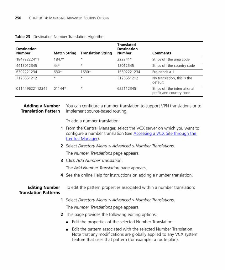
250 CHAPTER 14: MANAGING ADVANCED ROUTING OPTIONS
Adding a NumberTranslation Pattern
You can configure a number translation to support VPN translations or to implement source-based routing.
To add a number translation:
1 From the Central Manager, select the VCX server on which you want to configure a number translation (see Accessing a VCX Site through the Central Manager).
2 Select Directory Menu > Advanced > Number Translations.
The Number Translations page appears.
3 Click Add Number Translation.
The Add Number Translation page appears.
4 See the online Help for instructions on adding a number translation.
Editing NumberTranslation Patterns
To edit the pattern properties associated within a number translation:
1 Select Directory Menu > Advanced > Number Translations.
The Number Translations page appears.
2 This page provides the following editing options:
■ Edit the properties of the selected Number Translation.
■ Edit the pattern associated with the selected Number Translation. Note that any modifications are globally applied to any VCX system feature that uses that pattern (for example, a route plan).
Table 23 Destination Number Translation Algorithm
Destination Number Match String Translation String
Translated Destination Number Comments
18472222411 1847* * 2222411 Strips off the area code
4413012345 44* * 13012345 Strips off the country code
6302221234 630* 1630* 16302221234 Pre-pends a 1
3125551212 * * 3125551212 No translation, this is the default
011449622112345 01144* * 622112345 Strips off the international prefix and country code
Configuring Number Translation Patterns 251
■ Edit the requestor associated with the selected Number Translation. Note that any modifications are globally applied to any VCX system feature that uses that requestor.
■ Edit the phone profile associated with the selected Number Translation. Note that any modifications are globally applied to any VCX system feature that uses that profile.
■ Edit a holiday, week day band, day time band, or calendar band associated with the selected Number Translation. Note that any modifications are globally applied to any VCX system feature that uses that holiday or band.
3 See the online Help for instructions on modifying a number translation.
Deleting NumberTranslations
To delete a number translation pattern:
1 Select Directory Menu > Advanced > Number Translations.
2 You can delete one or multiple number translations:
■ To delete one number translation, click Delete in the Action column.
■ To delete multiple number translations, enter a check mark in the check box preceding each number translation, then click Delete Selected.
A confirmation box appears prompting you to confirm the delete action.
3 Click OK.
The Number Translations page refreshes and the deleted number translation is not listed.

252 CHAPTER 14: MANAGING ADVANCED ROUTING OPTIONS

15
CONFIGURING THE CALL REPORTS APPLICATIONThis chapter describes how to configure and use the VCX Call Reports application to view Call Detail Records (CDRs) collected by the server hosting the VCX Accounting service for each office (regional and any associated branches).
This chapter includes the following topics:
■ Call Detail Records Overview
■ Accessing the Call Reports Application
■ Downloading CDR Data
■ Managing the CDR Display and Generating Reports
■ Changing Configuration Preferences
■ Uninstalling the Call Reports Application
254 CHAPTER 15: CONFIGURING THE CALL REPORTS APPLICATION
Call Detail Records Overview
Call Detail Records (CDRs) contain information about each call that is processed by the VCX IP Telephony Suite.
CDR information can be generated by either a gateway, the IP Messaging server, or the call processor. These components send the CDR information directly to the Accounting server.
In general, the CDR generating component is responsible for deciding which CDR fields are appropriate for that particular type of component.
Typically, one CDR is generated by a component at the open (or start) of a call and another CDR is generated at the close (or end) of a call. Also, CDRs are generated by components on the ingress (incoming) and egress (outgoing) sides of a call.
The Accounting server supports the 3Queue protocol for receiving CDRs. 3Queue is a high-performance, reliable, 3Com proprietary protocol which uses ASN.1 formatted UDP messages. The UDP messages are sent to and received from the back-end servers.
The Call Reports application can retrieve and display Call Detail Records (CDRs) from a VCX or IP Messaging server. You can schedule the Call Reports application to retrieve CDRs at a specific time or you can retrieve them on demand. The Call Reports application also includes an option for creating reports that contain a subset of CDR information by filtering content.
The VCX Call Reports application is available on the 3Com Partner Access web site and is installed on a personal computer. The download and installation process is described in the VCX Installation Guide.
Microsoft .NET Framework version 2.0 or later must be installed on the personal computer before the VCX Call Reports application is installed. The .NET Framework software is available from the Microsoft Download Center.
See the VCX Maintenance Guide for information on configuring the Accounting and Call Records servers.

Accessing the Call Reports Application 255
Accessing the Call Reports Application
To access the VCX Call Reports application:
1 Log in to the personal computer running the VCX Call Reports application.
2 From the Start menu, click VCX Call Reports. The installation default location is Start | All Programs | 3Com VCX | VCX Call Reports.
The VCX Call Reports application main window appears. See Figure 30.
Figure 30 VCX Call Reports Application
The first time you start the VCX Call Reports application, the application prompts you for the following configuration information:
■ The IP address of the server hosting the VCX call processor.
■ The IP address of the server hosting the IP Messaging module.
■ Whether or not the Call Reports application should automatically retrieve CDRs.
■ The format used to display CDR fields.
You can modify any of these, and other, configuration preferences at any time. See Changing Configuration Preferences.
256 CHAPTER 15: CONFIGURING THE CALL REPORTS APPLICATION
Downloading CDR Data
CDRs can be downloaded from either the VCX or IP Messaging applications within the IP Telephony Suite, and can be retrieved either manually or automatically.
See the VCX Maintenance Guide for a description of VCX CDR fields.
See the IP Messaging Module Operations and System Administration Guide for information on the IP Messaging CDRs.
Retrieving VCX CDRsManually
To manually retrieve the latest VCX CDRs:
1 Select VCX in the Data selection pane.
2 From the Data menu, select VCX, then select Download VCX Records.
The Retrieving CDR records from server dialog box opens and the application begins retrieving CDRs.
3 When the status bar in the dialog box indicates the download is complete, click Close.
Retrieving VCX CDRsAutomatically
To automatically retrieve the latest VCX CDRs at a specific time interval:
1 Select VCX in the Data selection pane.
2 From the View menu, select Preferences.
3 In the Preferences dialog box, select the Retrieval tab.
4 Enter a check mark in the check box labeled VCX: Automatically retrieve every <hour> hours field.
5 In the <hour> field, enter how often, in hours, you want the VCX Call Reports application to retrieve CDRs.
6 Click OK.
Managing the CDR Display and Generating Reports 257
Managing the CDR Display and Generating Reports
This section provides a general description of the features available in the VCX Call Reports user interface. For detailed information, see the online help provided with the application.
You can control how CDRs are displayed:
■ Use the Display tab in the Preferences dialog box (from the View menu, select Preferences) to specify whether to display all records or a subset of records.
■ Use the Column Selection option (from the View menu, select Column Selection) to specify which fields should be displayed for each CDR.
■ Use the Grids menu option to customize how rows and columns are displayed. You can rearrange the sequence of columns, sort the data by column, and filter the displayed data (for example, show only CDRs generated on a specific date). You can then create a grid for each customized display.
You can use the Purge Old Records option (from the Data menu, select Purge Old Records) to remove CDRs locally (records are not removed from the VCX server).
You can use the Reports option to generate reports based on one of the supplied formats or create customized reports.
Changing Configuration Preferences
You can use the Preferences dialog box to change VCX server access information, such as server IP address. You can also use this dialog box to set CDR retrieval options and CDR display options.
1 Select VCX in the Data selection pane.
2 From the View menu, select Preferences.
3 In the Preferences dialog box, select the Server tab.
4 Enter the required information using Table 24 as a guide.

258 CHAPTER 15: CONFIGURING THE CALL REPORTS APPLICATION
Table 24 Call Reports Application Preferences Fields
Field Section Field Description
Network Addresses VCX IP Address Enter the IP address of the server storing the CDRs you want to view. This can be the server hosting:
■ An Accounting service — Enter the IP address associated with eth1 on the primary VCX call processor.
■ The Call Records service — If you have configured a Call Records service to collect CDRs from multiple Accounting services, enter the IP address of the server hosting the Call Records service. Typically, in a multi-site VCX system the Call Records service runs on separate Call Records server.
IPMSG IP Address Enter the IP address of the server hosting the primary IP Messaging module.
VCX CDR Login User Name Specifies the username of the account used to access the directory on the VCX server to which CDRs are written. The default is cworks.
Password Specifies the password of the account used to access the directory on the VCX server to which CDRs are written. The default is cworks.
Remote Directory Specifies the path on the VCX server where CDRs are located.
For a server hosting the Accounting service, the default path is:
/opt/3com/VCX/acctxml/db/export
For a Call Records Server, the default path is:
/opt/3com/VCX/bssxml/data/defaultGroup/outbox
The VCX-supplied Accounting service group defaultGroup is specified by default. However, this group, by default, contains no Accounting services and is disabled (see the VCX Maintenance Guide).
Uninstalling the Call Reports Application 259
5 Click OK.
Uninstalling the Call Reports Application
To uninstall the Call Reports application:
1 From the Start menu, click Control Panel.
The Control Panel window appears.
2 Click Add or Remove Programs.
The Add or Remove Programs window appears.
3 From the Currently installed programs column, select 3Com VCX Call Reports.
4 Click Change/Remove.
5 Click OK.
The program uninstalls. If prompted, reboot your computer.
IPMSG Server Login User Name Specifies the username of the account used to access the directory on the IP Messaging server to which CDRs are written. The default is app.
Password Specifies the password of the account used to access the directory on the IP Messaging server to which CDRs are written. The default is nice.
Remote Directory Specifies the default path on the IP Messaging server where CDRs are located. The default directory is:
/usr/app/app.dir/vmcdr.dir/
Table 24 Call Reports Application Preferences Fields (continued)
Field Section Field Description

INDEX
Numerics2102 Business telephone 1313101 Basic telephone 1293102 Business telephone 1283103 Manager’s telephone 135
Aaccess accounts 30, 37
admin 39dir 39manager 39user 39
accessing the LUI 127Accounting service 17adding
anonymous call restrictions 149attendant console 112bridge permission for an extension 161calendar bands 248call restrictions 150day time bands 248dial plans 204dial rules 208emergency defaults 89end points 241ERL 80holidays 246Out Dial patterns 243Out Dial patterns for routes 239Out Dial patterns to end points 241patterns (Directory Menu) 244patterns (Users Menu) 209requestors 246route plans 236routes 238trusted end points 242user directory to global directory 48user extensions to a hunt group 195users 66week day bands 247
address, IPCall Processor 132, 137
address, MACspecifying from a telephone 137viewing in telephone diagnostics 137
and phone extensions 103anonymous call restrictions 149attendant console
busy lamp flash 112configuring 110feature buttons 111managing 112
Attendant Serial Calling buttonattendant console 111
attendants 188call coverage
default 191scheduled 191
scheduling night coverage 192See also hunt groups
Authentication and Directory Servercomponent services 18
Authentication and Directory service 17
Bbasic telephones
accessing the LUI 126branch office
configuring data collection frequency for 54branch offices
adding to global directory 56listing
host regional office 52route configuration
for global IP Messaging 230for local IP Messaging 231
bridged extensionsadding permissions 161mapping extensions 162overview 157
bridged lines 155increasing or decreasing 158overview 157relationship to system appearance lines 158
business telephones
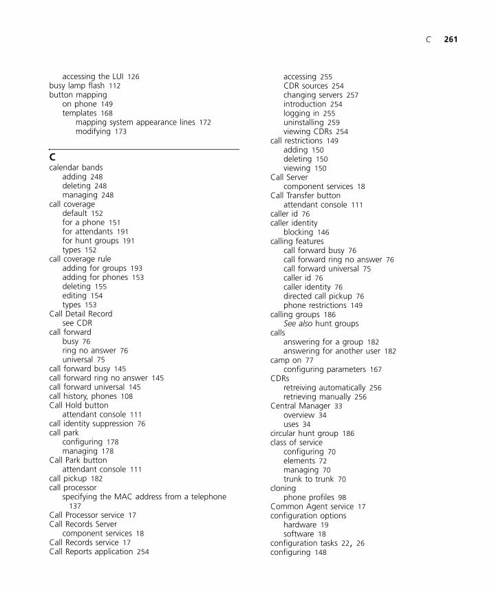
C 261
accessing the LUI 126busy lamp flash 112button mapping
on phone 149templates 168
mapping system appearance lines 172modifying 173
Ccalendar bands
adding 248deleting 248managing 248
call coveragedefault 152for a phone 151for attendants 191for hunt groups 191types 152
call coverage ruleadding for groups 193adding for phones 153deleting 155editing 154types 153
Call Detail Recordsee CDR
call forwardbusy 76ring no answer 76universal 75
call forward busy 145call forward ring no answer 145call forward universal 145call history, phones 108Call Hold button
attendant console 111call identity suppression 76call park
configuring 178managing 178
Call Park buttonattendant console 111
call pickup 182call processor
specifying the MAC address from a telephone 137
Call Processor service 17Call Records Server
component services 18Call Records service 17Call Reports application 254
accessing 255CDR sources 254changing servers 257introduction 254logging in 255uninstalling 259viewing CDRs 254
call restrictions 149adding 150deleting 150viewing 150
Call Servercomponent services 18
Call Transfer buttonattendant console 111
caller id 76caller identity
blocking 146calling features
call forward busy 76call forward ring no answer 76call forward universal 75caller id 76caller identity 76directed call pickup 76phone restrictions 149
calling groups 186See also hunt groups
callsanswering for a group 182answering for another user 182
camp on 77configuring parameters 167
CDRsretreiving automatically 256retrieving manually 256
Central Manager 33overview 34uses 34
circular hunt group 186class of service
configuring 70elements 72managing 70trunk to trunk 70
cloningphone profiles 98
Common Agent service 17configuration options
hardware 19software 18
configuration tasks 22, 26configuring 148
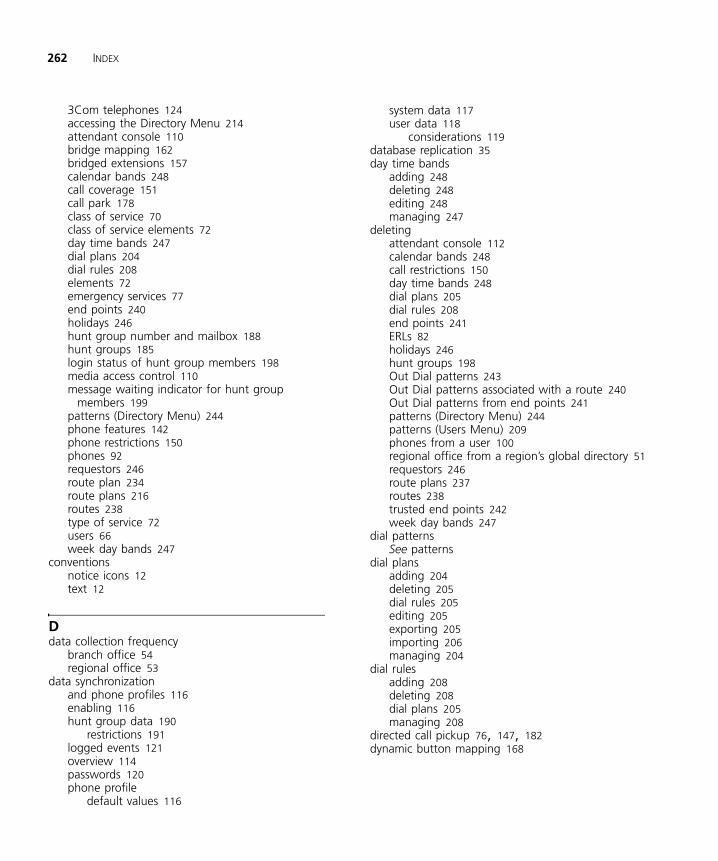
262 INDEX
3Com telephones 124accessing the Directory Menu 214attendant console 110bridge mapping 162bridged extensions 157calendar bands 248call coverage 151call park 178class of service 70class of service elements 72day time bands 247dial plans 204dial rules 208elements 72emergency services 77end points 240holidays 246hunt group number and mailbox 188hunt groups 185login status of hunt group members 198media access control 110message waiting indicator for hunt group
members 199patterns (Directory Menu) 244phone features 142phone restrictions 150phones 92requestors 246route plan 234route plans 216routes 238type of service 72users 66week day bands 247
conventionsnotice icons 12text 12
Ddata collection frequency
branch office 54regional office 53
data synchronizationand phone profiles 116enabling 116hunt group data 190
restrictions 191logged events 121overview 114passwords 120phone profile
default values 116
system data 117user data 118
considerations 119database replication 35day time bands
adding 248deleting 248editing 248managing 247
deletingattendant console 112calendar bands 248call restrictions 150day time bands 248dial plans 205dial rules 208end points 241ERLs 82holidays 246hunt groups 198Out Dial patterns 243Out Dial patterns associated with a route 240Out Dial patterns from end points 241patterns (Directory Menu) 244patterns (Users Menu) 209phones from a user 100regional office from a region’s global directory 51requestors 246route plans 237routes 238trusted end points 242week day bands 247
dial patternsSee patterns
dial plansadding 204deleting 205dial rules 205editing 205exporting 205importing 206managing 204
dial rulesadding 208deleting 208dial plans 205managing 208
directed call pickup 76, 147, 182dynamic button mapping 168

E 263
Eediting
attendant console basic information 112day time bands 248dial plans 205emergency defaults 89end points 241extensions on an attendant console 112feature mapping buttons on an attendant
console 112global directory regional office configuration 50holidays 246hunt groups 198Out Dial patterns 243patterns (Directory Menu) 244patterns (Users Menu) 209priorities of end points assigned to a route 239priorities of routes 239requestors 246routes 238trusted end points 242week day bands 247
elementsclass of service 72configuring 72
ELINconfiguring for ERL 86
emergency defaults 89Emergency Location Identification Number 77
See also ELINEmergency Response Location 77
See also ERLemergency services
configuring defaults 89managing ELINs for an ERL 86managing emergency gateways for an ERL 85managing emergency numbers for an ERL 84managing Emergency Response Locations 80managing IP addresses for an ERL 82overview 77roaming considerations 79
end pointsadding 241adding Out Dial patterns 241assigning to a route 239deleting 241deleting Out Dial patterns 241editing 241managing 240removing from a route 239trusted 242types 216
ERLadding 80adding an ELIN 86adding an emergency gateway 85adding an emergency number 84adding an IP address range 82deleting 82
event logsviewing 28
exportingdial plans 205
Gglobal directory 46
accessing 59adding remote branches 56adding user directory 48and call routing 46configuring data collection frequency 53editing user directory 50linking VCX Connect systems 46log files 61manually loading user directory 55manually resynchronizing user directory 54overview 46searching for end users 59
Global Voicemail Central Servercomponent services 18
group call pickup 182group paging 183groups
attendant 185call pickup 182hunt 185paging 183searching for 201
Hholidays
adding 246deleting 246editing 246managing 246
hunt groupsadding external user extensions 196adding phone extensions 195and data synchronization 190call coverage points
default 191scheduled 191
calling 186

264 INDEX
circular 186configuring MWI 199linear 186removing external user extensions 196removing local user extensions 195resetting ring sequence 198setting a ring tone 155timeout values 187types 186using the Search Menu 201
Iimporting
dial plans 206IP Messaging provisioning interface 34IP Messaging Server
component services 18IP Messaging server
importing data from IP Telephony server 114IP Messaging service 17IP Telephony and IP Messaging Server
component services 18IP Telephony Server
component services 18
Llinear hunt group 186listing
regional offices from a branch office 52Local User Interface
and PoE 126for telephones 125
log filefor global directory 61
LUISee Local User Interface
MMAC address
viewing in telephone diagnostics 137MAC address for a phone
configuring 110manager’s telephone 127managing
calendar bands 248day time bands 247dial plans 204dial rules 208holidays 246patterns (Directory Menu) 244
requestors 246route plan 234routes 238type of service 72week day bands 247
Media Access ControlSee MAC address
multi-siteconfiguration options 20route plan configuration 219
MWIhunt groups 199
NNCP IP Address 132, 137NCP MAC Address 137number translation (Directory Menu) 249
adding 250algorithms 249deleting 251modifying 250
number translation (Users Menu) 210adding 210deleting 210modifying 210
OOut Dial patterns
adding 243adding routes 239adding to end points 241deleting 243editing 243
Ppaging 183passwords
access to Administrator provisioning interface 30access to Users interface 66changing for Administrator provisioning interface
30for phone login 99synchronization 120
patternsadding (Directory Menu) 244deleting (Directory Menu) 244deleting (Users Menu) 209editing (Directory Menu) 244editing (Users Menu) 209managing (Users Menu) 209

R 265
personal speed dialsconfiguring 147
phone extensionsadding 99assigning to users 100deleting 100managing 98modifying 99roaming 103unassigning 102
phone featuresconfiguring 142
phone profilesand data synchronization 116cloning 98creating 93default profile 95deleting 97editing 96sample 94viewing member phones 96
phone registrationsviewing 106
phone settingsmodifying 104
phonesadding extensions 99bridging 157button test state 134call history 108configuration tasks 124deleting extensions 100editing extension settings 99IP address
viewing 132Local User Interface menu 125managing extensions 98mapping features to buttons 149profiles 93restrictions 149, 150setting a selective ring tone 155testing status lights 134viewing assigned profile 96viewing MAC address 137viewing MAC address through LUI 132viewing registrations 106viewing the serial number 132
Power over Ethernet cableand Local User Interface 126
powered Ethernet cableand LUI 126
primary servers 18Provisioning service 17
Rregional office
configuringdata collection frequency for 53
deleting regional office global directory 51listing 52
remote forward universal 147replication
database 35requestors
adding 246deleting 246editing 246managing 246
ring tonesselective 155
roaming 103and emergency services 79limitations 103
route configurationbetween regional offices 220for global IP Messaging
on a branch office 230for IP Messaging
on a regional office 228for IP Messaging clients
on a regional office 232for local IP Messaging
on a branch office 231from region to branch 225on a branch office 223to a gateway 226to Music On Hold service 228to voicemail service 228
route plan 234adding 236deleting 237
route plan configurationmultiple site 219single-site 217VCX Connect systems 216
route plan wizard 236route plans
requirements 216routes
adding 238adding Out Dial patterns for 239assigning end points 239configuring 238deleting 238deleting Out Dial patterns 240editing 238
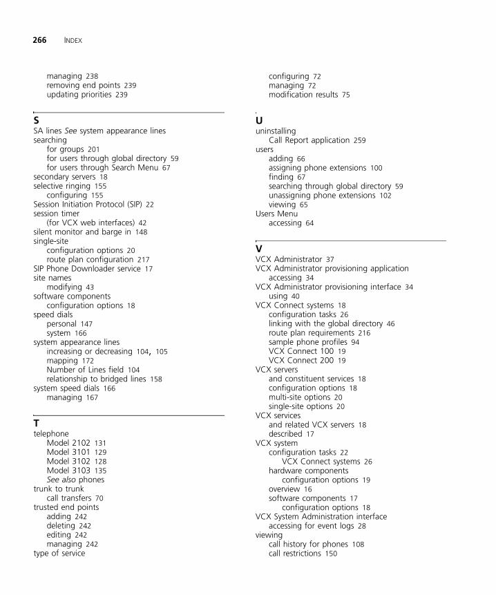
266 INDEX
managing 238removing end points 239updating priorities 239
SSA lines See system appearance linessearching
for groups 201for users through global directory 59for users through Search Menu 67
secondary servers 18selective ringing 155
configuring 155Session Initiation Protocol (SIP) 22session timer
(for VCX web interfaces) 42silent monitor and barge in 148single-site
configuration options 20route plan configuration 217
SIP Phone Downloader service 17site names
modifying 43software components
configuration options 18speed dials
personal 147system 166
system appearance linesincreasing or decreasing 104, 105mapping 172Number of Lines field 104relationship to bridged lines 158
system speed dials 166managing 167
Ttelephone
Model 2102 131Model 3101 129Model 3102 128Model 3103 135See also phones
trunk to trunkcall transfers 70
trusted end pointsadding 242deleting 242editing 242managing 242
type of service
configuring 72managing 72modification results 75
Uuninstalling
Call Report application 259users
adding 66assigning phone extensions 100finding 67searching through global directory 59unassigning phone extensions 102viewing 65
Users Menuaccessing 64
VVCX Administrator 37VCX Administrator provisioning application
accessing 34VCX Administrator provisioning interface 34
using 40VCX Connect systems 18
configuration tasks 26linking with the global directory 46route plan requirements 216sample phone profiles 94VCX Connect 100 19VCX Connect 200 19
VCX serversand constituent services 18configuration options 18multi-site options 20single-site options 20
VCX servicesand related VCX servers 18described 17
VCX systemconfiguration tasks 22
VCX Connect systems 26hardware components
configuration options 19overview 16software components 17
configuration options 18VCX System Administration interface
accessing for event logs 28viewing
call history for phones 108call restrictions 150
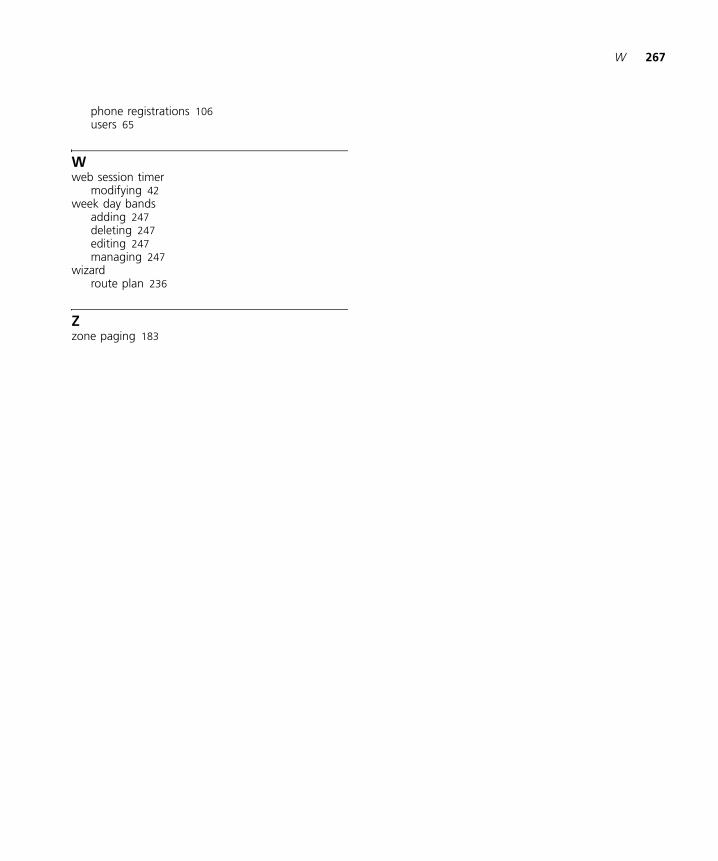
W 267
phone registrations 106users 65
Wweb session timer
modifying 42week day bands
adding 247deleting 247editing 247managing 247
wizardroute plan 236
Zzone paging 183