Embed Size (px)
Citation preview
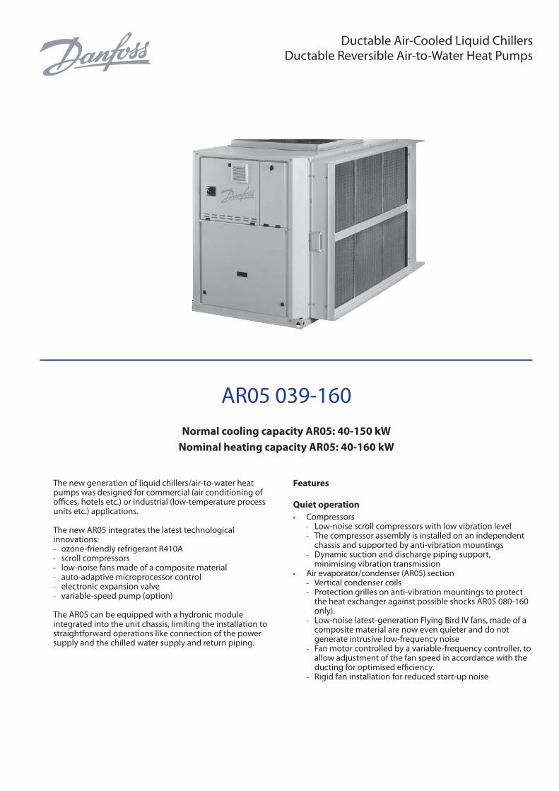
Ductable Air-Cooled Liquid Chillers Ductable Reversible Air-to-Water Heat Pumps
AR05 039-160
Normal cooling capacity AR05: 40-150 kW
Nominal heating capacity AR05: 40-160 kW
The new generation of liquid chillers/air-to-water heat pumps was designed for commercial (air conditioning of offi ces, hotels etc.) or industrial (low-temperature process units etc.) applications.
The new AR05 integrates the latest technologi cal innovations: - ozone-friendly refrigerant R410A - scroll compressors - low-noise fans made of a composite material - auto-adaptive microprocessor control - electronic expansion valve - variable-speed pump (option)
The AR05 can be equipped with a hydronic module integrated into the unit chassis, limiting the installation to straightforward operations like connection of the power supply and the chilled water supply and return piping.
Features
Quiet operation
• Compressors - Low-noise scroll compressors with low vibration level - The compressor assembly is installed on an independent
chassis and supported by anti-vibration mountings - Dynamic suction and discharge piping support,
minimising vibration transmission• Air evaporator/condenser (AR05) section
- Vertical condenser coils - Protection grilles on anti-vibration mountings to protect
the heat exchanger against possible shocks AR05 080-160 only).
- Low-noise latest-generation Flying Bird IV fans, made of a composite material are now even quieter and do not generate intrusive low-frequency noise
- Fan motor controlled by a variable-frequency controller, to allow adjustment of the fan speed in accordance with the ducting for optimised effi ciency.
- Rigid fan installation for reduced start-up noise

2VDGFF102
Economical operation
• Variable-speed pump (option) - The control algorithm adjusts the water fl ow rate in
accordance with the actual system requirements. This saves energy and makes the fl ow control valve unnecessary.
• Variable-speed fan - Variable-speed ventilation permits adjustment to any duct
type and variation of the air fl ow rate for maximised unit EERs and COPs under any operating conditions.
• Increased energy effi ciency at part load - The refrigerant circuit includes several compressors
connected in parallel. At part load, around 99% of the operating time, only the compressors that are absolutely necessary operate. At these conditions the compressors operating are more energy effi cient, as they use the total condenser and evaporator capacity.
- The electronic expansion device (EXV) allows operation at a lower condensing pressure (EER, COP and ESEER optimisation).
- Dynamic superheat management for better utilisation of the water heat exchanger surface.
- Defrost cycle optimisation (AR05)• Reduced maintenance costs
- Maintenance-free scroll compressors - Fast diagnosis of possible incidents and their history via
the control system - R410A refrigerant is easier to use than other refrigerant
blends
Environmental care
• Ozone-friendly R410A refrigerant - Chlorine-free refrigerant of the HFC group with zero ozone
depletion potential - High-density refrigerant, therefore less refrigerant required - Very effi cient - gives an increased energy effi ciency ratio
(EER, COP and ESEER)• Leak-tight refrigerant circuit
- Brazed refrigerant connections for increased leak-tightness - Reduction of leaks due to reduced vibration levels and
elimination of capillary tubes (TXVs) - Verifi cation of pressure transducers and temperature
sensors without transferring refrigerant charge
Supply air connection frame
Easy and fast installation
• Physical features - Flying Bird IV fans controlled by a variable-frequency
controller to provide up to 240 Pa available pressure (depending on the size) at nominal fl ow rate
- Flow control in accordance with the ducting for optimised effi ciency with the possibility to program a maximum supply air fl ow.
- Supply air duct connection frame. - Suction air connection frame standard for sizes AR05
039-078 - Suction air fi lters optional (AR05 039-078 only) - Small unit footprint with a low height (1371 mm) for easy
installation in most buildings - The unit is enclosed by easily removable panels, covering all
components (except air heat exchanger and fans).• Integrated hydronic module (option)
- Centrifugal low or high-pressure water pump (as required), based on the pressure loss of the hydronic installation
Hydronic module
- Single or dual water pump (as required) with operating time balancing and automatic changeover to the back-up pump if a fault develops
- Water fi lter protects the water pump against circulating debris
- Pressure measurement, using two pressure transducers and allowing indication of water fl ow rate, water pressure and lack of water.
- High-capacity membrane expansion tank ensures pressurisation of the water circuit
- Overpressure valve, set to 4 bar - Speed variator on the pumps (option) to ensure the
correct fl ow rate, based on the system requirements - Thermal insulation and frost protection down to -20°C,
using an electric resistance heater (see table of options)• Simplifi ed electrical connections
- A single power supply point without neutral - Main disconnect switch with high trip capacity - Transformer for safe 24 V control circuit supply included
• Fast commissioning - Systematic factory operation test before shipment - Quick-test function for step-by-step verifi cation of the
instruments, electrical components and motors

3VDGFF102
Variable fan speed controller
- The navigation uses intuitive tree-structure menus, similar to the Internet navigators. They are user-friendly and permit quick access to the principal operat-ing parameters: number of compressors operating, suction/discharge pressure, compressor operating hours, set point, air temperature, entering/leaving water temperature
CCN operating mode
A simple two-wire communication bus between the RS485 port and the CCN off ers multiple remote control, monitoring and diagnostic possibilities. Danfoss off ers a vast choice of control products, specially designed to control, manage and supervise the operation of an air conditioning system. Please consult your Danfoss representative for more information on these products.
Remote operating mode with dry contacts (standard)
- Start/stop: opening of this contact will shut down the unit - Dual set point: closing of this contact activates a second
set point (example: unoccupied mode) - Water pump 1 and 2 control (contacts supplied with the
hydronic module option)*: these outputs control the contactors of one or two water heat exchanger water pumps
- Alarm indication: this volt-free contact indicates the presence of a major fault that has led to the shut-down of one or two refrigerant circuits
- Demand limit 1 and 2: closing of these contacts limits the maximum unit capacity to three predefi ned values
- User safety: this contact can be used for any customer safety loop, closing of the contact generates a specifi c alarm
Remote interface (accessory)
This interface allows access to the same menus as the unit interface and can be installed up to 300 m away. This accessory includes a box that can be mounted inside the building. The power supply is provided via a 220 V/24 V transformer supplied.
Superior reliability
• State-of-the-art concept - Cooperation with specialist laboratories and use of limit
simulation tools (fi nite element calculations) for the design of the critical components, e.g. motor supports, suction/discharge piping etc.
• Auto-adaptive control - Control algorithm prevents excessive compressor cycling
and permits reduction of the water quantity in the hydronic circuit
- Hydronic module with integrated pressure transducers allowing measurement of the water pressure at two points, as well as measurement of the water fl ow rate and detection of lack of water and pressure. This considerably reduces the risk of problems such as frost accumulation on the water heat exchanger.
- Automatic compressor unloading in case of abnormally high condensing pressure. If an anomaly occurs (e.g. fouled air heat exchanger coil, fan failure) Aquasnap continues to operate, but at reduced capacity.
• Exceptional endurance tests - Corrosion resistance tests in salt mist in the laboratory - Accelerated ageing test on components that are
submitted to continuous operation: compressor piping, fan supports
- Transport simulation test in the laboratory on a vibrating table.
Control System
The control system combines intelligence with operating simplicity. The control system constantly monitors all machine parameters and precisely manages the operation of compressors, expansion devices, fans and of the water heat exchanger water pump for optimum energy effi ciency.
Control Interface
\\MAINMENU\STATUS
Circuit B Total Capacity
CAPB_T 0 %DEM_LIM 100 %SP 4.2 °CCTRL_PNT -28.9 °CEMSTOP dsable
ENTERSTART/STOP
• Energy management - Seven-day internal time schedule clock: permits unit on/
off control and operation at a second set point - Set point reset based on the outside air temperature or the
return water temperature or on the water heat exchanger delta T
- Master/slave control of two units operating in parallel with operating time equalisation and automatic change-over in case of a unit fault (accessory).
- Change-over based on the outside air temperature• Integrated features
- Night mode: capacity and fan speed limitation for reduced noise level
- With hydronic module: water pressure display and water fl ow rate calculation
• Ease-of-use - The new backlighted LCD interface includes a manual
control potentiometer to ensure legibility under any lighting conditions.
- The information is displayed clearly in English, French, German, Italian and Spanish (for other languages please consult Danfoss)
4VDGFF102
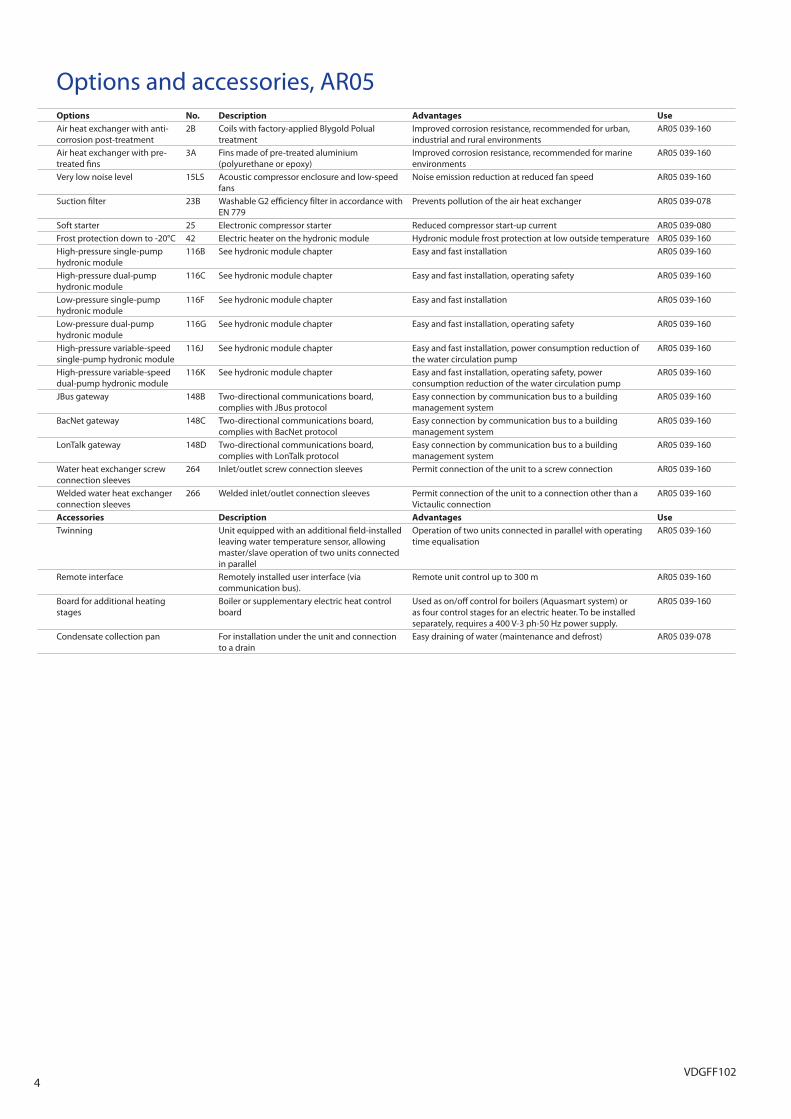
Options and accessories, AR05Options No. Description Advantages Use
Air heat exchanger with anti-corrosion post-treatment
2B Coils with factory-applied Blygold Polual treatment
Improved corrosion resistance, recommended for urban, industrial and rural environments
AR05 039-160
Air heat exchanger with pre-treated fi ns
3A Fins made of pre-treated aluminium (polyurethane or epoxy)
Improved corrosion resistance, recommended for marine environments
AR05 039-160
Very low noise level 15LS Acoustic compressor enclosure and low-speed fans
Noise emission reduction at reduced fan speed AR05 039-160
Suction fi lter 23B Washable G2 effi ciency fi lter in accordance with EN 779
Prevents pollution of the air heat exchanger AR05 039-078
Soft starter 25 Electronic compressor starter Reduced compressor start-up current AR05 039-080Frost protection down to -20°C 42 Electric heater on the hydronic module Hydronic module frost protection at low outside temperature AR05 039-160High-pressure single-pump hydronic module
116B See hydronic module chapter Easy and fast installation AR05 039-160
High-pressure dual-pump hydronic module
116C See hydronic module chapter Easy and fast installation, operating safety AR05 039-160
Low-pressure single-pump hydronic module
116F See hydronic module chapter Easy and fast installation AR05 039-160
Low-pressure dual-pump hydronic module
116G See hydronic module chapter Easy and fast installation, operating safety AR05 039-160
High-pressure variable-speed single-pump hydronic module
116J See hydronic module chapter Easy and fast installation, power consumption reduction of the water circulation pump
AR05 039-160
High-pressure variable-speed dual-pump hydronic module
116K See hydronic module chapter Easy and fast installation, operating safety, power consumption reduction of the water circulation pump
AR05 039-160
JBus gateway 148B Two-directional communications board, complies with JBus protocol
Easy connection by communication bus to a building management system
AR05 039-160
BacNet gateway 148C Two-directional communications board, complies with BacNet protocol
Easy connection by communication bus to a building management system
AR05 039-160
LonTalk gateway 148D Two-directional communications board, complies with LonTalk protocol
Easy connection by communication bus to a building management system
AR05 039-160
Water heat exchanger screw connection sleeves
264 Inlet/outlet screw connection sleeves Permit connection of the unit to a screw connection AR05 039-160
Welded water heat exchanger connection sleeves
266 Welded inlet/outlet connection sleeves Permit connection of the unit to a connection other than a Victaulic connection
AR05 039-160
Accessories Description Advantages Use
Twinning Unit equipped with an additional fi eld-installed leaving water temperature sensor, allowing master/slave operation of two units connected in parallel
Operation of two units connected in parallel with operating time equalisation
AR05 039-160
Remote interface Remotely installed user interface (via communication bus).
Remote unit control up to 300 m AR05 039-160
Board for additional heating stages
Boiler or supplementary electric heat control board
Used as on/off control for boilers (Aquasmart system) or as four control stages for an electric heater. To be installed separately, requires a 400 V-3 ph-50 Hz power supply.
AR05 039-160
Condensate collection pan For installation under the unit and connection to a drain
Easy draining of water (maintenance and defrost) AR05 039-078
5VDGFF102
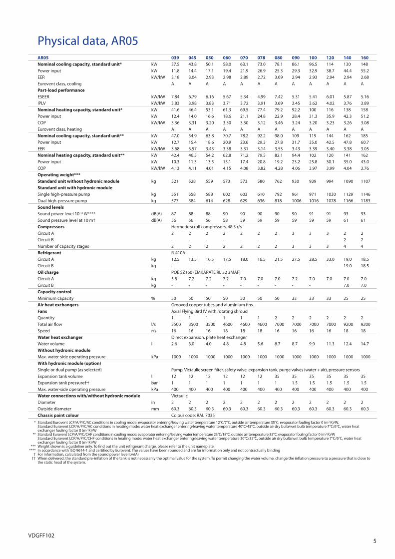
Physical data, AR05AR05 039 045 050 060 070 078 080 090 100 120 140 160
Nominal cooling capacity, standard unit* kW 37.5 43.8 50.1 58.0 63.1 73.0 78.1 86.1 96.5 114 130 148Power input kW 11.8 14.4 17.1 19.4 21.9 26.9 25.3 29.3 32.9 38.7 44.4 55.2EER kW/kW 3.18 3.04 2.93 2.98 2.89 2.72 3.09 2.94 2.93 2.94 2.94 2.68Eurovent class, cooling A A A A A A A A A A A APart-load performance
ESEER kW/kW 7.84 6.79 6.16 5.67 5.34 4.99 7.42 5.31 5.41 6.01 5.87 5.16IPLV kW/kW 3.83 3.98 3.83 3.71 3.72 3.91 3.69 3.45 3.62 4.02 3.76 3.89Nominal heating capacity, standard unit* kW 41.6 46.4 53.1 61.3 69.5 77.4 79.2 92.2 100 116 138 158Power input kW 12.4 14.0 16.6 18.6 21.1 24.8 22.9 28.4 31.3 35.9 42.3 51.2COP kW/kW 3.36 3.31 3.20 3.30 3.30 3.12 3.46 3.24 3.20 3.23 3.26 3.08Eurovent class, heating A A A A A A A A A A A ANominal cooling capacity, standard unit** kW 47.0 54.9 63.8 70.7 78.2 92.2 98.0 109 119 144 162 185Power input kW 12.7 15.4 18.6 20.9 23.6 29.3 27.8 31.7 35.0 42.5 47.8 60.7EER kW/kW 3.68 3.57 3.43 3.38 3.31 3.14 3.53 3.43 3.39 3.40 3.38 3.05Nominal heating capacity, standard unit** kW 42.4 46.5 54.2 62.8 71.2 79.5 82.1 94.4 102 120 141 162Power input kW 10.3 11.3 13.5 15.1 17.4 20.8 19.2 23.2 25.8 30.1 35.0 43.0COP kW/kW 4.13 4.11 4.01 4.15 4.08 3.82 4.28 4.06 3.97 3.99 4.04 3.76Operating weight***
Standard unit without hydronic module kg 521 528 559 573 573 580 762 930 939 994 1090 1107Standard unit with hydronic module
Single high-pressure pump kg 551 558 588 602 603 610 792 961 971 1030 1129 1146Dual high-pressure pump kg 577 584 614 628 629 636 818 1006 1016 1078 1166 1183Sound levels
Sound power level 10-12 W**** dB(A) 87 88 88 90 90 90 90 90 91 91 93 93Sound pressure level at 10 m† dB(A) 56 56 56 58 59 59 59 59 59 59 61 61Compressors Hermetic scroll compressors, 48.3 r/sCircuit A 2 2 2 2 2 2 2 3 3 3 2 2Circuit B - - - - - - - - - - 2 2Number of capacity stages 2 2 2 2 2 2 2 3 3 3 4 4Refrigerant R-410ACircuit A kg 12.5 13.5 16.5 17.5 18.0 16.5 21.5 27.5 28.5 33.0 19.0 18.5Circuit B kg - - - - - - - - - - 19.0 18.5Oil charge POE SZ160 (EMKARATE RL 32 3MAF)Circuit A kg 5.8 7.2 7.2 7.2 7.0 7.0 7.0 7.2 7.0 7.0 7.0 7.0Circuit B kg - - - - - - - - - 7.0 7.0Capacity control
Minimum capacity % 50 50 50 50 50 50 50 33 33 33 25 25Air heat exchangers Grooved copper tubes and aluminium fi nsFans Axial Flying Bird IV with rotating shroudQuantity 1 1 1 1 1 1 2 2 2 2 2 2Total air fl ow l/s 3500 3500 3500 4600 4600 4600 7000 7000 7000 7000 9200 9200Speed r/s 16 16 16 18 18 18 16 16 16 16 18 18Water heat exchanger Direct expansion. plate heat exchangerWater volume l 2.6 3.0 4.0 4.8 4.8 5.6 8.7 8.7 9.9 11.3 12.4 14.7Without hydronic module
Max. water-side operating pressure kPa 1000 1000 1000 1000 1000 1000 1000 1000 1000 1000 1000 1000With hydronic module (option)
Single or dual pump (as selected) Pump, Victaulic screen fi lter, safety valve, expansion tank, purge valves (water + air), pressure sensorsExpansion tank volume l 12 12 12 12 12 12 35 35 35 35 35 35Expansion tank pressure†† bar 1 1 1 1 1 1 1 1.5 1.5 1.5 1.5 1.5Max. water-side operating pressure kPa 400 400 400 400 400 400 400 400 400 400 400 400Water connections with/without hydronic module VictaulicDiameter in 2 2 2 2 2 2 2 2 2 2 2 2Outside diameter mm 60.3 60.3 60.3 60.3 60.3 60.3 60.3 60.3 60.3 60.3 60.3 60.3Chassis paint colour Colour code: RAL 7035
* Standard Eurovent LCP/A/P/C/AC conditions in cooling mode: evaporator entering/leaving water temperature 12°C/7°C, outside air temperature 35°C, evaporator fouling factor 0 (m2 K)/W. Standard Eurovent LCP/A/P/C/AC conditions in heating mode: water heat exchanger entering/leaving water temperature 40°C/45°C, outside air dry bulb/wet bulb temperature 7°C/6°C, water heat
exchanger fouling factor 0 (m2 K)/W ** Standard Eurovent LCP/A/P/C/CHF conditions in cooling mode: evaporator entering/leaving water temperature 23°C/18°C, outside air temperature 35°C, evaporator fouling factor 0 (m2 K)/W Standard Eurovent LCP/A/P/C/CHF conditions in heating mode: water heat exchanger entering/leaving water temperature 30°C/35°C, outside air dry bulb/wet bulb temperature 7°C/6°C, water heat
exchanger fouling factor 0 (m2 K)/W *** Weight shown is a guideline only. To fi nd out the unit refrigerant charge, please refer to the unit nameplate. **** In accordance with ISO 9614-1 and certifi ed by Eurovent. The values have been rounded and are for information only and not contractually binding † For information, calculated from the sound power level Lw(A) †† When delivered, the standard pre-infl ation of the tank is not necessarily the optimal value for the system. To permit changing the water volume, change the infl ation pressure to a pressure that is close to
the static head of the system.
6VDGFF102
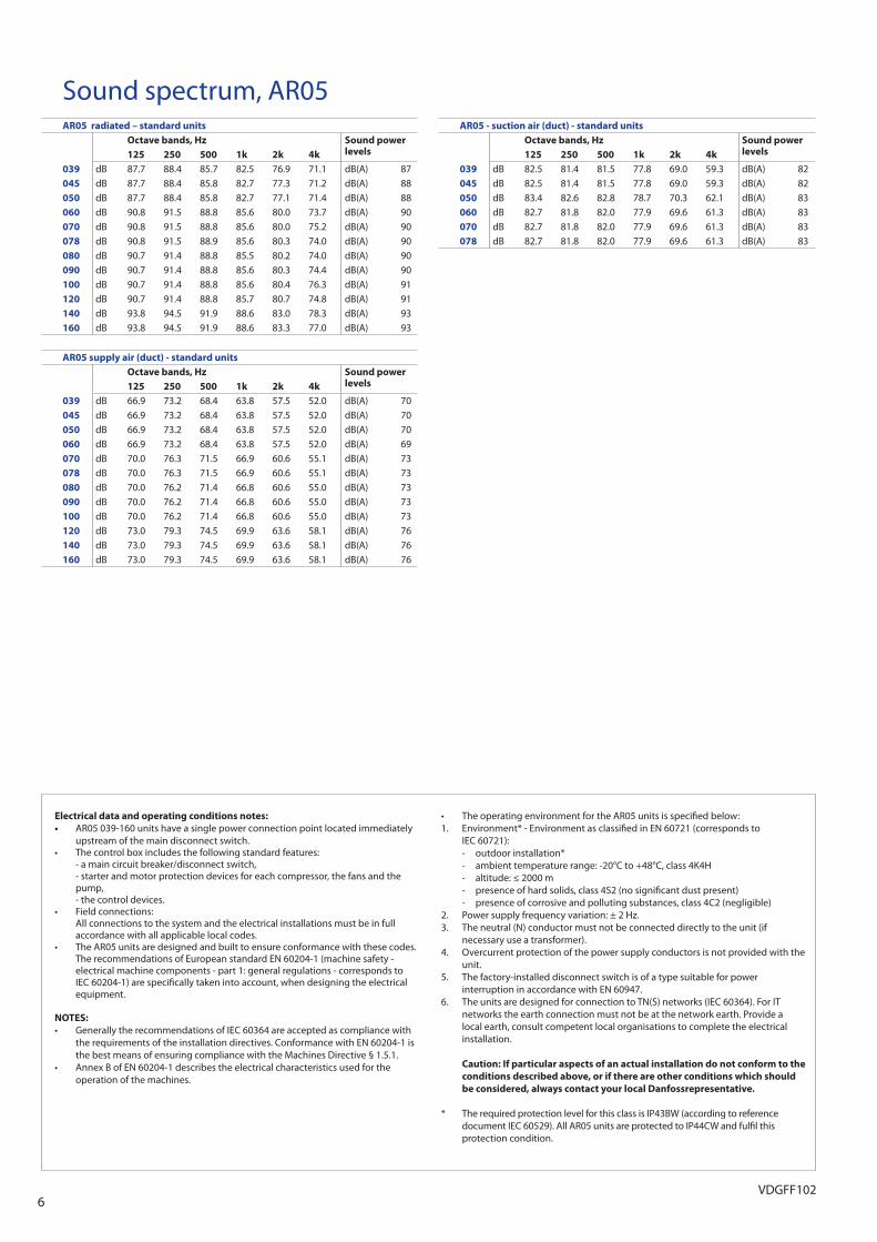
Electrical data and operating conditions notes:
• AR05 039-160 units have a single power connection point located immediately upstream of the main disconnect switch.
• The control box includes the following standard features: - a main circuit breaker/disconnect switch, - starter and motor protection devices for each compressor, the fans and the
pump, - the control devices.• Field connections: All connections to the system and the electrical installations must be in full
accordance with all applicable local codes.• The AR05 units are designed and built to ensure conformance with these codes.
The recommendations of European standard EN 60204-1 (machine safety - electrical machine components - part 1: general regulations - corresponds to IEC 60204-1) are specifi cally taken into account, when designing the electrical equipment.
NOTES:
• Generally the recommendations of IEC 60364 are accepted as compliance with the requirements of the installation directives. Conformance with EN 60204-1 is the best means of ensuring compliance with the Machines Directive § 1.5.1.
• Annex B of EN 60204-1 describes the electrical characteristics used for the operation of the machines.
• The operating environment for the AR05 units is specifi ed below:1. Environment* - Environment as classifi ed in EN 60721 (corresponds to
IEC 60721): - outdoor installation* - ambient temperature range: -20°C to +48°C, class 4K4H - altitude: ≤ 2000 m - presence of hard solids, class 4S2 (no signifi cant dust present) - presence of corrosive and polluting substances, class 4C2 (negligible)2. Power supply frequency variation: ± 2 Hz.3. The neutral (N) conductor must not be connected directly to the unit (if
necessary use a transformer).4. Overcurrent protection of the power supply conductors is not provided with the
unit.5. The factory-installed disconnect switch is of a type suitable for power
interruption in accordance with EN 60947.6. The units are designed for connection to TN(S) networks (IEC 60364). For IT
networks the earth connection must not be at the network earth. Provide a local earth, consult competent local organisations to complete the electrical installation.
Caution: If particular aspects of an actual installation do not conform to the
conditions described above, or if there are other conditions which should
be considered, always contact your local Danfossrepresentative.
* The required protection level for this class is IP43BW (according to reference document IEC 60529). All AR05 units are protected to IP44CW and fulfi l this protection condition.
Sound spectrum, AR05AR05 radiated – standard units
Octave bands, Hz Sound power levels125 250 500 1k 2k 4k
039 dB 87.7 88.4 85.7 82.5 76.9 71.1 dB(A) 87045 dB 87.7 88.4 85.8 82.7 77.3 71.2 dB(A) 88050 dB 87.7 88.4 85.8 82.7 77.1 71.4 dB(A) 88060 dB 90.8 91.5 88.8 85.6 80.0 73.7 dB(A) 90070 dB 90.8 91.5 88.8 85.6 80.0 75.2 dB(A) 90078 dB 90.8 91.5 88.9 85.6 80.3 74.0 dB(A) 90080 dB 90.7 91.4 88.8 85.5 80.2 74.0 dB(A) 90090 dB 90.7 91.4 88.8 85.6 80.3 74.4 dB(A) 90100 dB 90.7 91.4 88.8 85.6 80.4 76.3 dB(A) 91120 dB 90.7 91.4 88.8 85.7 80.7 74.8 dB(A) 91140 dB 93.8 94.5 91.9 88.6 83.0 78.3 dB(A) 93160 dB 93.8 94.5 91.9 88.6 83.3 77.0 dB(A) 93
AR05 supply air (duct) - standard units
Octave bands, Hz Sound power levels125 250 500 1k 2k 4k
039 dB 66.9 73.2 68.4 63.8 57.5 52.0 dB(A) 70045 dB 66.9 73.2 68.4 63.8 57.5 52.0 dB(A) 70050 dB 66.9 73.2 68.4 63.8 57.5 52.0 dB(A) 70060 dB 66.9 73.2 68.4 63.8 57.5 52.0 dB(A) 69070 dB 70.0 76.3 71.5 66.9 60.6 55.1 dB(A) 73078 dB 70.0 76.3 71.5 66.9 60.6 55.1 dB(A) 73080 dB 70.0 76.2 71.4 66.8 60.6 55.0 dB(A) 73090 dB 70.0 76.2 71.4 66.8 60.6 55.0 dB(A) 73100 dB 70.0 76.2 71.4 66.8 60.6 55.0 dB(A) 73120 dB 73.0 79.3 74.5 69.9 63.6 58.1 dB(A) 76140 dB 73.0 79.3 74.5 69.9 63.6 58.1 dB(A) 76160 dB 73.0 79.3 74.5 69.9 63.6 58.1 dB(A) 76
AR05 - suction air (duct) - standard units
Octave bands, Hz Sound power levels125 250 500 1k 2k 4k
039 dB 82.5 81.4 81.5 77.8 69.0 59.3 dB(A) 82045 dB 82.5 81.4 81.5 77.8 69.0 59.3 dB(A) 82050 dB 83.4 82.6 82.8 78.7 70.3 62.1 dB(A) 83060 dB 82.7 81.8 82.0 77.9 69.6 61.3 dB(A) 83070 dB 82.7 81.8 82.0 77.9 69.6 61.3 dB(A) 83078 dB 82.7 81.8 82.0 77.9 69.6 61.3 dB(A) 83

7VDGFF102
Electrical data, AR05AR05 without hydronic module 039 045 050 060 070 078 080 090 100 120 140 160
Power circuit
Nominal power supply V-ph-Hz 400-3-50Voltage range V 360-440Control circuit supply 24 V via internal transformerMaximum start-up current (Un)*
Standard unit A 115.8 134.3 144.3 146.3 170.8 210.3 216.6 174.6 201.6 246.6 226.1 276.6Unit with electronic starter option A 77.8 90.2 97.3 99.3 114.8 140.3 146.6Unit power factor at maximum capacity** 0.82 0.82 0.84 0.85 0.85 0.84 0.84 0.85 0.85 0.84 0.85 0.84Maximum operating power input** kW 21.4 24.2 26.4 29.8 32.0 36.6 39.4 46.1 49.4 56.3 64.0 73.2Nominal unit operating current draw*** A 31.3 34.3 38.3 43.3 46.3 58.3 64.6 68.1 72.6 90.6 92.6 116.6Maximum operating current draw (Un)**** A 35.3 40.3 46.3 50.3 55.3 66.3 72.6 78.6 86.1 102.6 110.6 132.6Maximum operating current draw (Un-10%)† A 38.3 43.7 50.3 54.7 60.3 72.3 78.6 85.2 93.6 111.6 120.6 145.0Customer-side unit power reserve Customer reserve at the 24 V control power circuitShort-circuit stability and protection See table “Short-circuit stability current” below
* Maximum instantaneous start-up current at operating limit values (maximum operating current of the smallest compressor(s) + fan current + locked rotor current of the largest compressor). ** Power input, compressors and fans, at the unit operating limits (saturated suction temperature 10°C, saturated condensing temperature 65°C) and nominal voltage of 400 V (data given on the unit
nameplate). *** Standardised Eurovent conditions: water heat exchanger entering/leaving water temperature 12°C/7°C, outside air temperature 35°C. **** Maximum unit operating current at maximum unit power input and 400 V (values given on the unit nameplate). † Maximum unit operating current at maximum unit power input and 360 V.
Short-circuit stability current (TN system*) - standard unit (main disconnect without fuse)
AR05 039 045 050 060 070 078 080 090 100 120 140 160
Value with unspecifi ed upstream protection
Short-term current at 1s - Icw – kA rms 3.36 3.36 3.36 3.36 3.36 3.36 3.36 5.62 5.62 5.62 5.62 5.62Admissible peak current - Ipk - kA pk 20 20 20 20 20 15 15 20 20 15 20 15Max. value with upstream protection by circuit breaker
Conditional short-circuit current Icc - kA rms 40 40 40 40 40 40 40 40 40 40 30 30Schneider circuit breaker - Compact series NS100H NS100H NS100H NS100H NS100H NS100H NS100H NS100H NS160H NS160H NS250H NS250HReference No.** 29670 29670 29670 29670 29670 29670 29670 29670 30670 30670 31671 31671
* Earthing system type ** If another current limitation protection system is used, its time-current and thermal constraint (I²t) trip characteristics must be at least equivalent to those of the recommended Schneider circuit breaker. Contact your nearest Danfoss offi ce. The short-circuit stability current values above are in accordance with the TN system.
8VDGFF102
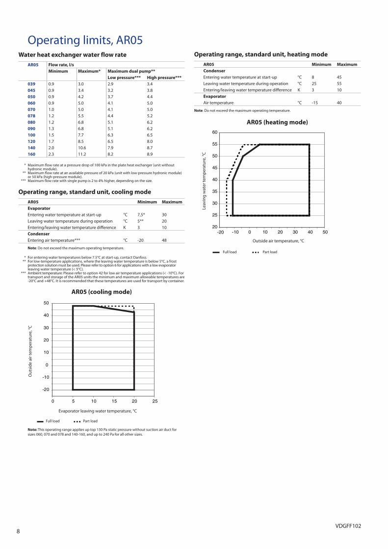
Operating limits, AR05Water heat exchanger water flow rate
AR05 Flow rate, l/s
Minimum Maximum* Maximum dual pump**
Low pressure*** High pressure***
039 0.9 3.0 2.9 3.4045 0.9 3.4 3.2 3.8050 0.9 4.2 3.7 4.4060 0.9 5.0 4.1 5.0070 1.0 5.0 4.1 5.0078 1.2 5.5 4.4 5.2080 1.2 6.8 5.1 6.2090 1.3 6.8 5.1 6.2100 1.5 7.7 6.3 6.5120 1.7 8.5 6.5 8.0140 2.0 10.6 7.9 8.7160 2.3 11.2 8.2 8.9
* Maximum fl ow rate at a pressure drop of 100 kPa in the plate heat exchanger (unit without hydronic module).
** Maximum fl ow rate at an available pressure of 20 kPa (unit with low-pressure hydronic module) or 50 kPa (high-pressure module).
*** Maximum fl ow rate with single pump is 2 to 4% higher, depending on the size.
Operating range, standard unit, cooling mode
AR05 Minimum Maximum
Evaporator
Entering water temperature at start-up °C 7,5* 30Leaving water temperature during operation °C 5** 20Entering/leaving water temperature diff erence K 3 10Condenser
Entering air temperature*** °C -20 48
Note: Do not exceed the maximum operating temperature.
* For entering water temperatures below 7.5°C at start-up, contact Danfoss. ** For low-temperature applications, where the leaving water temperature is below 5°C, a frost
protection solution must be used. Please refer to option 6 for applications with a low evaporator leaving water temperature (< 5°C).
*** Ambient temperature: Please refer to option 42 for low air temperature applications (< -10°C). For transport and storage of the AR05 units the minimum and maximum allowable temperatures are -20°C and +48°C. It is recommended that these temperatures are used for transport by container.
AR05 (cooling mode)
-20
-10
0
10
20
30
40
50
0 5 10 15 20 25
Full load Part load
Note: This operating range applies up top 130 Pa static pressure without suction air duct for sizes 060, 070 and 078 and 140-160, and up to 240 Pa for all other sizes.
Operating range, standard unit, heating mode
AR05 Minimum Maximum
Condenser
Entering water temperature at start-up °C 8 45Leaving water temperature during operation °C 25 55Entering/leaving water temperature diff erence K 3 10Evaporator
Air temperature °C -15 40
Note: Do not exceed the maximum operating temperature.
AR05 (heating mode)
20
25
30
35
40
45
50
55
60
-20 -10 0 10 20 30 40 50
Leav
ing
wat
er te
mp
erat
ure,
°C
Outside air temperature, °C
Full load Part load
Out
side
air
tem
per
atur
e, °C
Evaporator leaving water temperature, °C
9VDGFF102
1
1061 50
6512
22
1132
127 1796
2050
575 900
6512
22
50
1000
1000
860
149
419
222
519
1371
2109
2
2
2
2
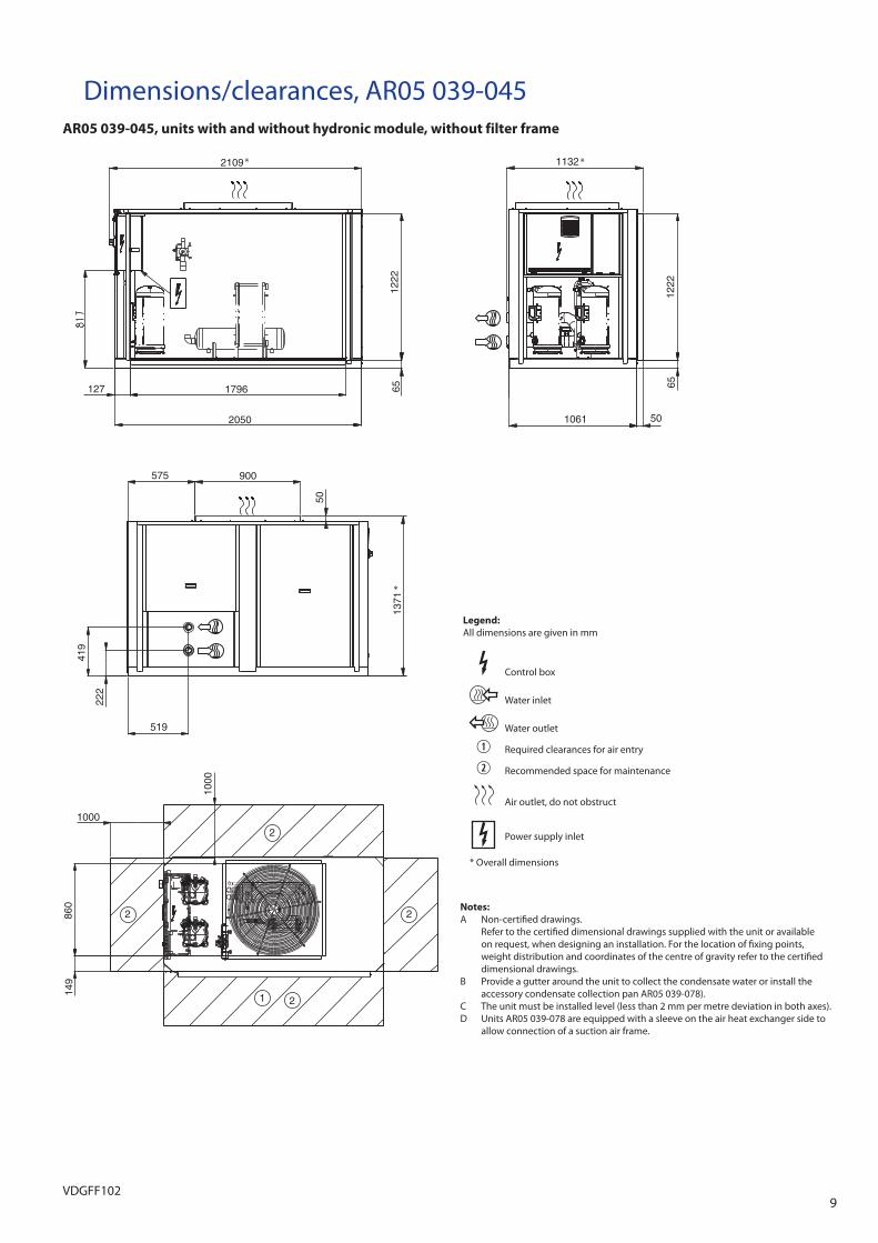
Legend:
All dimensions are given in mm
Control box
Water inlet
Water outlet
Required clearances for air entry
Recommended space for maintenance
Air outlet, do not obstruct
Power supply inlet
Notes:
A Non-certifi ed drawings. Refer to the certifi ed dimensional drawings supplied with the unit or available
on request, when designing an installation. For the location of fi xing points, weight distribution and coordinates of the centre of gravity refer to the certifi ed dimensional drawings.
B Provide a gutter around the unit to collect the condensate water or install the accessory condensate collection pan AR05 039-078).
C The unit must be installed level (less than 2 mm per metre deviation in both axes).D Units AR05 039-078 are equipped with a sleeve on the air heat exchanger side to
allow connection of a suction air frame.
Dimensions/clearances, AR05 039-045AR05 039-045, units with and without hydronic module, without filter frame
* *
*
* Overall dimensions
10VDGFF102
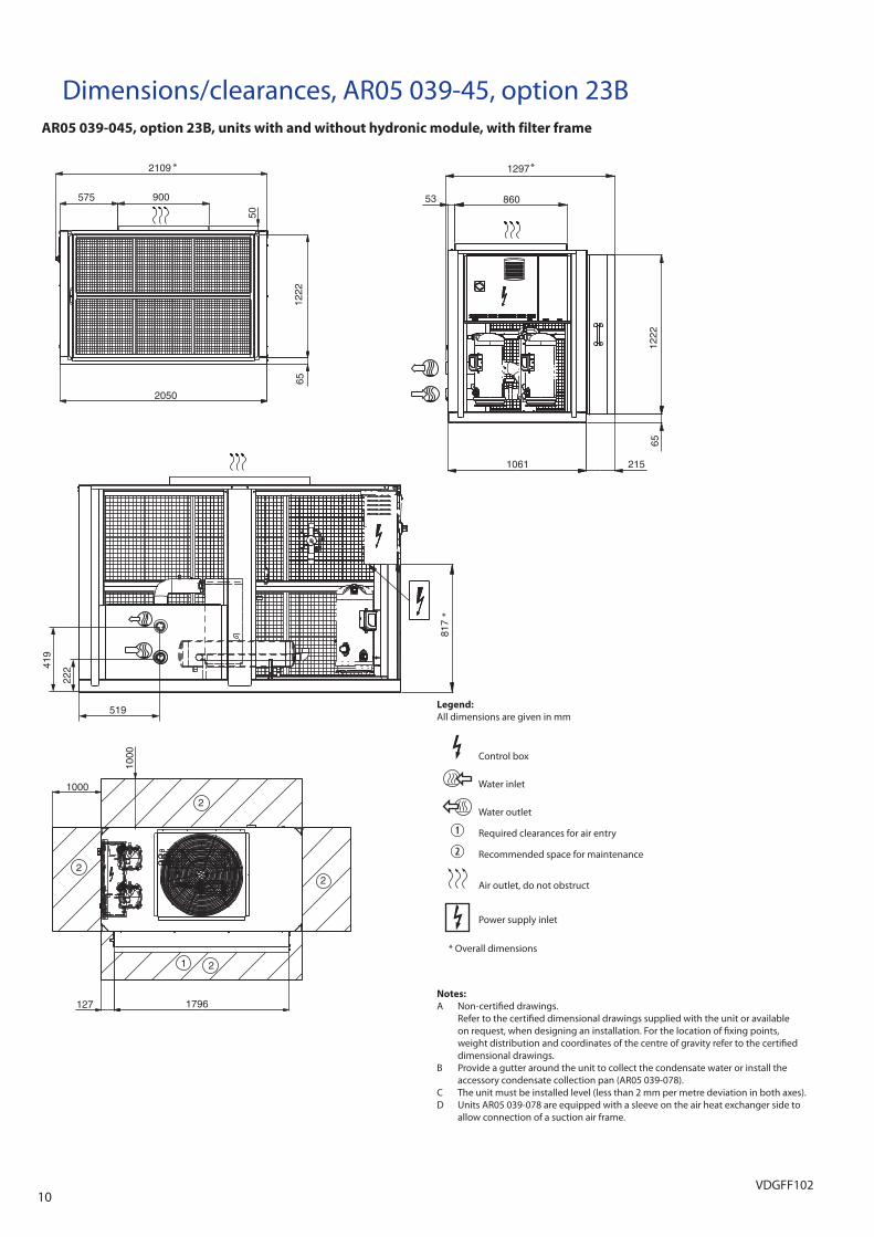
Notes:
A Non-certifi ed drawings. Refer to the certifi ed dimensional drawings supplied with the unit or available
on request, when designing an installation. For the location of fi xing points, weight distribution and coordinates of the centre of gravity refer to the certifi ed dimensional drawings.
B Provide a gutter around the unit to collect the condensate water or install the accessory condensate collection pan (AR05 039-078).
C The unit must be installed level (less than 2 mm per metre deviation in both axes).D Units AR05 039-078 are equipped with a sleeve on the air heat exchanger side to
allow connection of a suction air frame.
Dimensions/clearances, AR05 039-45, option 23BAR05 039-045, option 23B, units with and without hydronic module, with filter frame
Legend:
All dimensions are given in mm
Control box
Water inlet
Water outlet
Required clearances for air entry
Recommended space for maintenance
Air outlet, do not obstruct
Power supply inlet
2109
900575
50
2050
6512
22
1297
53 860
1222
65
215106181
7
1
1000
1000
127 1796
2
2
2
2
419
222
519
* *
*
* Overall dimensions
11VDGFF102
1
1
1061 50
6512
22
1132
127 1796
2050
575 900
50
6512
22
50
1000
1000
860
149
419
222
519
1371
2142
2
2
2
2
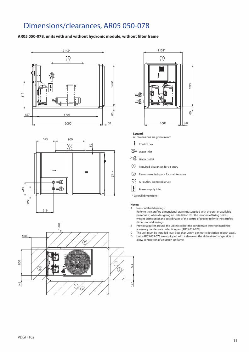
Dimensions/clearances, AR05 050-078AR05 050-078, units with and without hydronic module, without filter frame
Notes:
A Non-certifi ed drawings. Refer to the certifi ed dimensional drawings supplied with the unit or available
on request, when designing an installation. For the location of fi xing points, weight distribution and coordinates of the centre of gravity refer to the certifi ed dimensional drawings.
B Provide a gutter around the unit to collect the condensate water or install the accessory condensate collection pan (AR05 039-078).
C The unit must be installed level (less than 2 mm per metre deviation in both axes).D Units AR05 039-078 are equipped with a sleeve on the air heat exchanger side to
allow connection of a suction air frame.
Legend:All dimensions are given in mm
Control box
Water inlet
Water outlet
Required clearances for air entry
Recommended space for maintenance
Air outlet, do not obstruct
Power supply inlet
1
2
* *
*
* Overall dimensions
12VDGFF102
2307
900575
50
2050 215
6512
22
1297
53 860
1222
65
2151061
817
1
1
1000
1000
646
127
127 1796
2
2
2
2
419
222
519
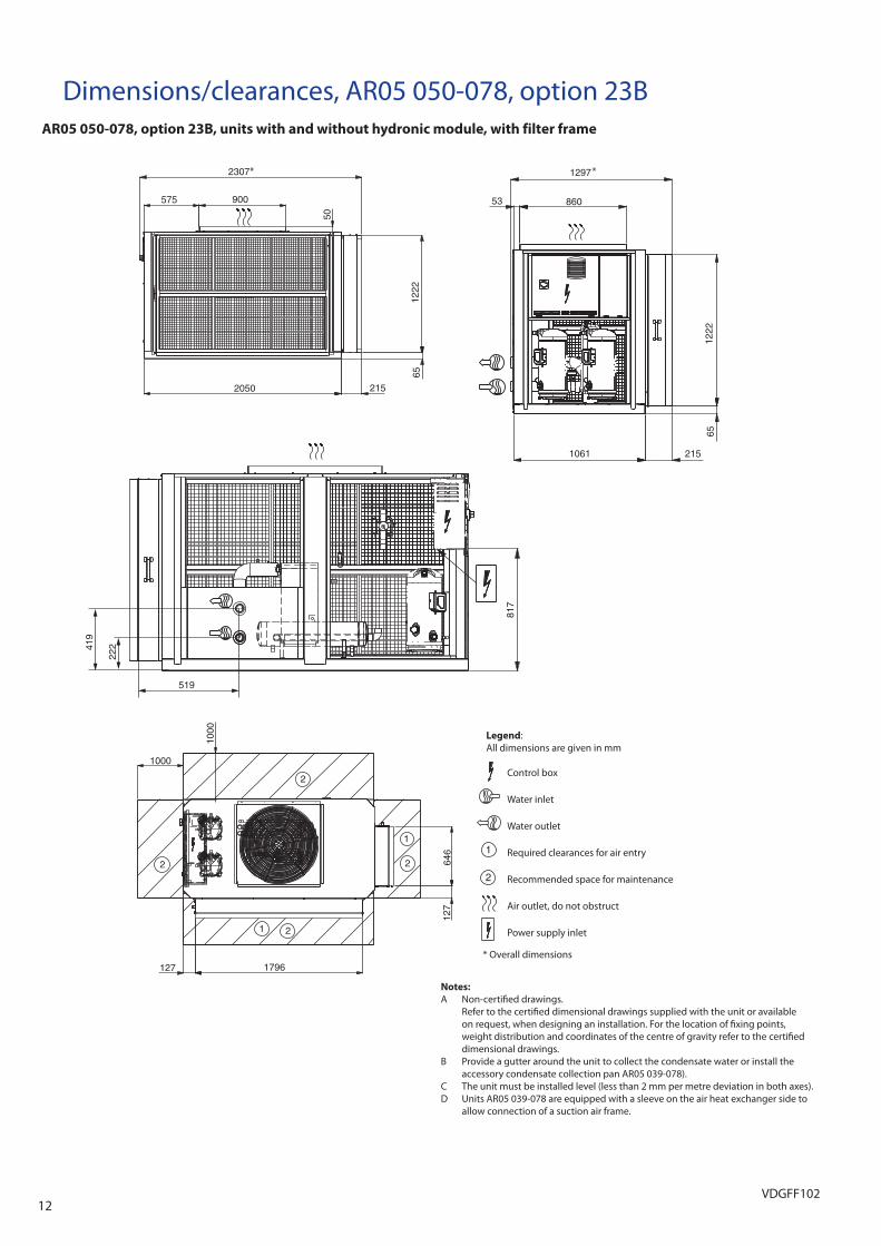
Dimensions/clearances, AR05 050-078, option 23BAR05 050-078, option 23B, units with and without hydronic module, with filter frame
Notes:
A Non-certifi ed drawings. Refer to the certifi ed dimensional drawings supplied with the unit or available
on request, when designing an installation. For the location of fi xing points, weight distribution and coordinates of the centre of gravity refer to the certifi ed dimensional drawings.
B Provide a gutter around the unit to collect the condensate water or install the accessory condensate collection pan AR05 039-078).
C The unit must be installed level (less than 2 mm per metre deviation in both axes).D Units AR05 039-078 are equipped with a sleeve on the air heat exchanger side to
allow connection of a suction air frame.
Legend:All dimensions are given in mm
Control box
Water inlet
Water outlet
Required clearances for air entry
Recommended space for maintenance
Air outlet, do not obstruct
Power supply inlet
1
2
* *
* Overall dimensions
13VDGFF102
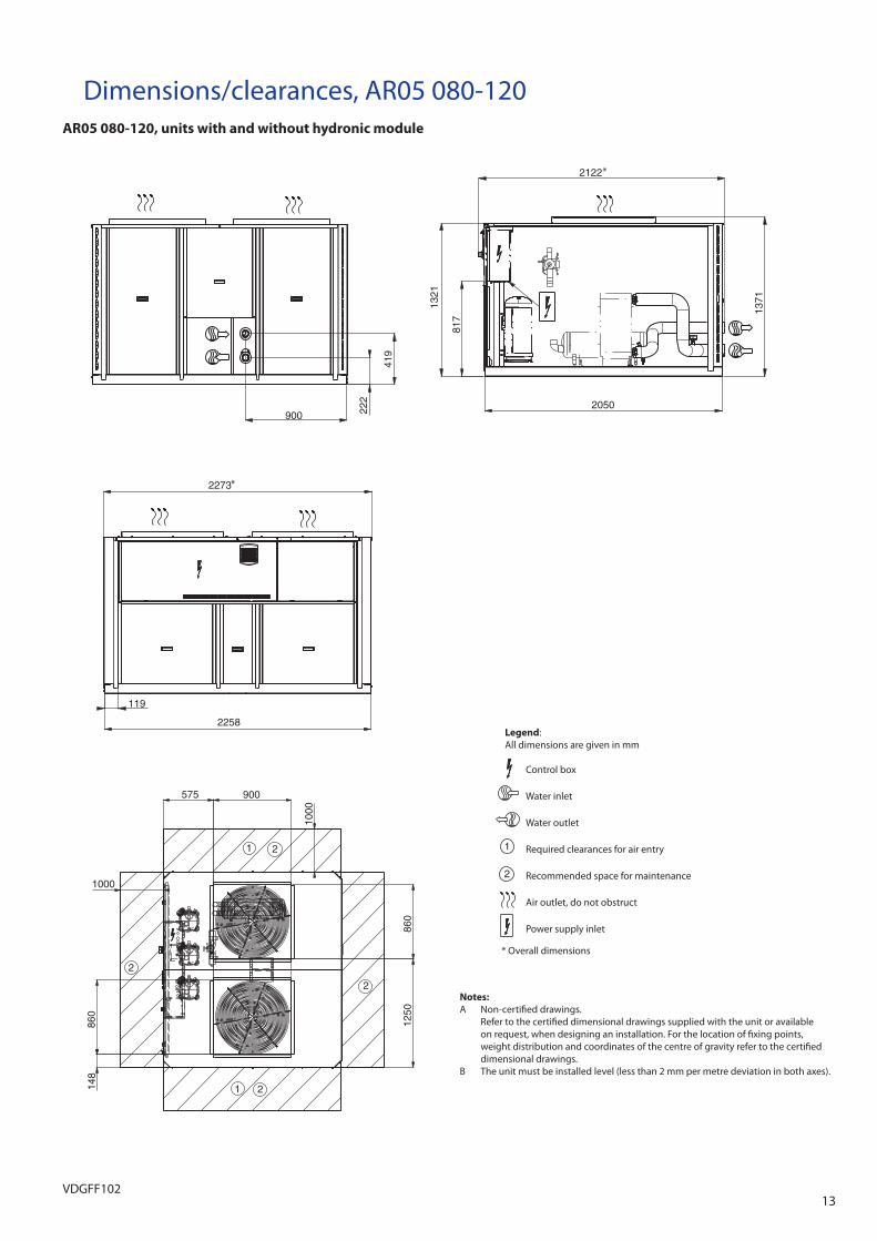
Dimensions/clearances, AR05 080-120AR05 080-120, units with and without hydronic module
900 222
419
817
1321
2050
1371
2122
2273
1192258
1
1
575 900
1000
1250
860
148
860
1000
2
2
2
2
Notes:
A Non-certifi ed drawings. Refer to the certifi ed dimensional drawings supplied with the unit or available
on request, when designing an installation. For the location of fi xing points, weight distribution and coordinates of the centre of gravity refer to the certifi ed dimensional drawings.
B The unit must be installed level (less than 2 mm per metre deviation in both axes).
Legend:All dimensions are given in mm
Control box
Water inlet
Water outlet
Required clearances for air entry
Recommended space for maintenance
Air outlet, do not obstruct
Power supply inlet
1
2
*
*
* Overall dimensions
14VDGFF102
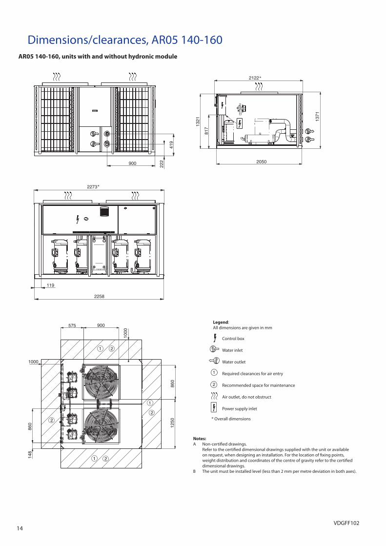
Dimensions/clearances, AR05 140-160AR05 140-160, units with and without hydronic module
Notes:
A Non-certifi ed drawings. Refer to the certifi ed dimensional drawings supplied with the unit or available
on request, when designing an installation. For the location of fi xing points, weight distribution and coordinates of the centre of gravity refer to the certifi ed dimensional drawings.
B The unit must be installed level (less than 2 mm per metre deviation in both axes).
Legend:All dimensions are given in mm
Control box
Water inlet
Water outlet
Required clearances for air entry
Recommended space for maintenance
Air outlet, do not obstruct
Power supply inlet
1
2
900 222
419
2273
119
2258
1
1
1
860
1250
1000
860
148
575 900
1000
2122
1371
1321
817
2050
2
2
2
2
*
*
* Overall dimensions
15VDGFF102
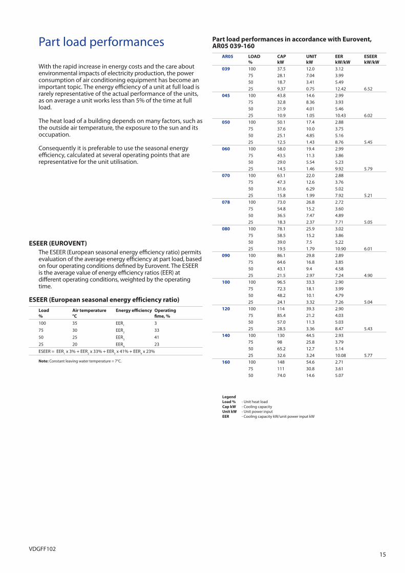
Part load performances
With the rapid increase in energy costs and the care about environmental impacts of electricity production, the power consumption of air conditioning equipment has become an important topic. The energy effi ciency of a unit at full load is rarely representative of the actual performance of the units, as on average a unit works less than 5% of the time at full load.
The heat load of a building depends on many factors, such as the outside air temperature, the exposure to the sun and its occupation.
Consequently it is preferable to use the seasonal energy effi ciency, calculated at several operating points that are representative for the unit utilisation.
Part load performances in accordance with Eurovent, AR05 039-160
AR05 LOAD
%
CAP
kW
UNIT
kW
EER
kW/kW
ESEER
kW/kW
039 100 37.5 12.0 3.1275 28.1 7.04 3.9950 18.7 3.41 5.4925 9.37 0.75 12.42 6.52
045 100 43.8 14.6 2.9975 32.8 8.36 3.9350 21.9 4.01 5.4625 10.9 1.05 10.43 6.02
050 100 50.1 17.4 2.8875 37.6 10.0 3.7550 25.1 4.85 5.1625 12.5 1.43 8.76 5.45
060 100 58.0 19.4 2.9975 43.5 11.3 3.8650 29.0 5.54 5.2325 14.5 1.46 9.92 5.79
070 100 63.1 22.0 2.8875 47.3 12.6 3.7650 31.6 6.29 5.0225 15.8 1.99 7.92 5.21
078 100 73.0 26.8 2.7275 54.8 15.2 3.6050 36.5 7.47 4.8925 18.3 2.37 7.71 5.05
080 100 78.1 25.9 3.0275 58.5 15.2 3.8650 39.0 7.5 5.2225 19.5 1.79 10.90 6.01
090 100 86.1 29.8 2.8975 64.6 16.8 3.8550 43.1 9.4 4.5825 21.5 2.97 7.24 4.90
100 100 96.5 33.3 2.9075 72.3 18.1 3.9950 48.2 10.1 4.7925 24.1 3.32 7.26 5.04
120 100 114 39.3 2.9075 85.4 21.2 4.0350 57.0 11.3 5.0325 28.5 3.36 8.47 5.43
140 100 130 44.5 2.9375 98 25.8 3.7950 65.2 12.7 5.1425 32.6 3.24 10.08 5.77
160 100 148 54.6 2.7175 111 30.8 3.6150 74.0 14.6 5.07
ESEER (EUROVENT)
The ESEER (European seasonal energy effi ciency ratio) permits evaluation of the average energy effi ciency at part load, based on four operating conditions defi ned by Eurovent. The ESEER is the average value of energy effi ciency ratios (EER) at diff erent operating conditions, weighted by the operating time.
ESEER (European seasonal energy efficiency ratio)
Load
%
Air temperature
°C
Energy effi ciency Operating
fi me, %
100 35 EER1
3
75 30 EER2
33
50 25 EER3
41
25 20 EER4
23
ESEER = EER1 x 3% + EER
2 x 33% + EER
3 x 41% + EER
4 x 23%
Note: Constant leaving water temperature = 7°C.
Legend
Load % - Unit heat load Cap kW - Cooling capacity Unit kW - Unit power input EER - Cooling capacity kW/unit power input kW
16VDGFF102
AR
05
03
9-1
60 C
on
de
nse
r e
nte
rin
g a
ir t
em
pe
ratu
re,
°C
LWT
25
30
35
40
45
CA
PC
OM
PU
NIT
CO
OL
CO
OL
CA
PC
OM
PU
NIT
CO
OL
CO
OL
CA
PC
OM
PU
NIT
CO
OL
CO
OL
CA
PC
OM
PU
NIT
CO
OL
CO
OL
CA
PC
OM
PU
NIT
CO
OL
CO
OL
°Ck
Wk
Wk
Wl/
sk
Pa
kW
kW
kW
l/s
kP
ak
Wk
Wk
Wl/
sk
Pa
kW
kW
kW
l/s
kP
ak
Wk
Wk
Wl/
sk
Pa
03
95
38.7
9.93
11.9
1.84
43.6
37.1
10.8
12.7
1.76
39.8
35.2
11.9
13.8
1.68
35.8
32.9
13.1
15.0
1.57
31.1
30.2
14.6
16.5
1.44
26.1
04
545
.011
.713
.62.
1452
.643
.413
.014
.92.
0749
.340
.914
.516
.41.
9544
.537
.715
.917
.81.
7938
.434
.117
.519
.41.
6232
.30
50
52.5
13.9
16.1
2.50
51.0
50.0
15.4
17.5
2.38
46.6
47.0
17.0
19.2
2.24
41.7
43.7
18.9
21.0
2.08
36.4
39.8
21.0
23.1
1.90
30.8
06
060
.215
.718
.42.
8751
.157
.617
.220
.02.
7447
.054
.419
.121
.82.
5942
.250
.221
.023
.82.
3936
.445
.723
.225
.92.
1730
.50
70
65.9
17.8
20.6
3.14
62.6
62.9
19.5
22.3
2.99
57.3
59.1
21.5
24.2
2.82
51.1
54.8
23.7
26.4
2.61
44.4
49.9
26.1
28.8
2.38
37.2
07
876
.622
.224
.93.
6562
.772
.724
.226
.93.
4656
.468
.326
.429
.03.
2549
.763
.528
.931
.63.
0242
.958
.231
.834
.42.
7735
.90
80
81.6
21.0
25.6
3.89
43.5
77.6
22.8
27.4
3.69
39.5
73.1
24.9
29.4
3.48
35.3
68.3
27.2
31.7
3.25
31.0
62.9
29.8
34.3
3.00
26.6
09
089
.523
.328
.04.
2654
.185
.625
.830
.44.
0849
.780
.428
.533
.13.
8344
.174
.131
.536
.13.
5337
.867
.434
.839
.43.
2131
.61
00
101
26.7
31.1
4.83
60.2
96.4
29.2
33.7
4.59
54.9
90.3
32.1
36.5
4.30
48.6
83.5
35.3
39.7
3.98
42.1
75.8
38.8
43.1
3.61
35.2
12
012
032
.436
.75.
7065
.711
335
.239
.55.
4059
.310
738
.342
.55.
0852
.599
.342
.046
.14.
7345
.691
.246
.150
.24.
3438
.71
40
136
36.1
41.6
6.49
70.5
130
39.6
45.1
6.19
64.3
122
43.5
48.9
5.82
57.2
113
48.0
53.4
5.40
49.5
103
52.9
58.3
4.92
41.5
16
015
645
.250
.67.
4275
.914
849
.254
.57.
0368
.313
953
.658
.96.
6060
.412
958
.864
.06.
1452
.311
864
.669
.75.
6344
.20
39
741
.110
.112
.11.
9648
.839
.411
.012
.91.
8844
.637
.412
.114
.01.
7840
.135
.013
.315
.21.
6734
.932
.214
.816
.71.
5329
.40
45
47.9
11.9
13.8
2.28
58.0
46.2
13.2
15.1
2.20
54.5
43.7
14.7
16.6
2.08
49.3
40.2
16.2
18.1
1.92
42.6
36.5
17.7
19.6
1.74
35.9
05
055
.614
.216
.42.
6556
.153
.015
.717
.82.
5351
.449
.917
.319
.42.
3846
.046
.419
.221
.32.
2140
.342
.521
.323
.42.
0234
.20
60
64.0
16.0
18.8
3.05
56.5
61.2
17.6
20.3
2.92
52.1
57.8
19.4
22.2
2.76
46.9
53.5
21.4
24.1
2.55
40.5
48.8
23.6
26.3
2.33
34.1
07
070
.118
.221
.03.
3469
.566
.919
.922
.73.
1963
.662
.921
.924
.63.
0056
.858
.424
.126
.82.
7849
.353
.226
.529
.22.
5341
.40
78
81.5
22.7
25.4
3.89
70.4
77.4
24.8
27.4
3.69
63.3
72.8
26.9
29.6
3.47
55.9
67.7
29.5
32.1
3.23
48.2
62.0
32.3
34.9
2.96
40.4
08
086
.721
.526
.14.
1348
.282
.523
.428
.03.
9343
.977
.725
.430
.03.
7139
.272
.627
.832
.33.
4634
.567
.030
.434
.93.
1929
.60
90
95.4
23.8
28.5
4.55
60.4
91.3
26.3
30.9
4.35
55.5
85.8
29.1
33.7
4.09
49.3
79.2
32.1
36.6
3.78
42.4
72.1
35.4
39.9
3.44
35.5
10
010
827
.431
.85.
1567
.010
329
.934
.44.
8960
.996
.132
.837
.24.
5853
.988
.936
.140
.44.
2446
.780
.839
.643
.83.
8539
.11
20
127
33.2
37.5
6.06
73.1
121
36.1
40.3
5.75
66.0
113
39.2
43.4
5.40
58.5
106
42.9
47.0
5.03
50.9
97.0
46.9
51.0
4.63
43.2
14
014
536
.942
.46.
9178
.313
840
.445
.96.
5971
.513
044
.349
.86.
2063
.612
148
.954
.35.
7555
.111
053
.859
.15.
2446
.21
60
166
46.3
51.7
7.90
84.6
157
50.4
55.7
7.48
76.1
147
54.8
60.1
7.03
67.4
137
60.0
65.2
6.54
58.4
126
65.7
70.9
6.00
49.3
03
91
044
.910
.512
.42.
1457
.943
.011
.313
.32.
0552
.840
.812
.414
.31.
9547
.438
.213
.715
.61.
8241
.335
.215
.217
.01.
6834
.80
45
52.4
12.2
14.1
2.50
67.0
50.6
13.5
15.5
2.42
63.0
47.9
15.0
16.9
2.29
57.2
44.2
16.5
18.4
2.11
49.6
40.2
18.1
20.0
1.92
42.0
05
060
.414
.716
.82.
8864
.357
.716
.118
.32.
7559
.054
.417
.819
.92.
6053
.050
.719
.721
.82.
4246
.546
.421
.823
.92.
2239
.60
60
69.9
16.5
19.3
3.34
65.7
67.0
18.2
20.9
3.20
60.6
63.3
20.1
22.8
3.02
54.6
58.6
22.1
24.8
2.80
47.3
53.5
24.3
26.9
2.56
39.9
07
076
.818
.921
.63.
6781
.073
.220
.623
.33.
5074
.268
.922
.525
.33.
2966
.263
.924
.827
.53.
0557
.658
.327
.229
.92.
7848
.40
78
89.3
23.5
26.2
4.26
83.3
84.8
25.6
28.3
4.05
75.0
79.8
27.9
30.5
3.81
66.2
74.2
30.4
33.1
3.54
57.3
68.1
33.2
35.8
3.25
48.1
08
094
.822
.326
.94.
5356
.290
.224
.228
.84.
3151
.285
.126
.330
.94.
0645
.879
.528
.733
.23.
8040
.273
.331
.335
.73.
5034
.60
90
105
24.5
29.2
4.99
70.6
100
27.1
31.7
4.78
65.0
94.1
29.9
34.5
4.49
57.8
87.1
32.9
37.5
4.16
50.0
79.5
36.3
40.8
3.80
42.0
10
011
928
.232
.65.
6778
.411
330
.835
.35.
3871
.210
533
.938
.35.
0362
.897
.337
.241
.64.
6554
.388
.440
.745
.04.
2245
.41
20
139
34.4
38.6
6.64
85.7
132
37.4
41.6
6.30
77.2
124
40.6
44.8
5.92
68.6
115
44.3
48.5
5.52
59.7
106
48.3
52.4
5.07
50.6
14
015
838
.143
.77.
5791
.415
141
.747
.27.
2283
.514
245
.651
.16.
7974
.313
250
.255
.66.
3064
.412
055
.260
.55.
7554
.1
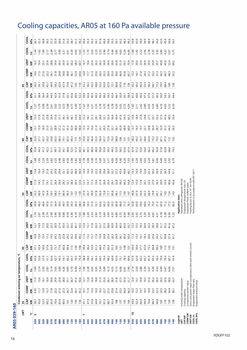
Cooling capacities, AR05 at 160 Pa available pressure
L
eg
en
d:
LW
T
Leav
ing
wat
er te
mp
erat
ure
C
AP
kW
C
oolin
g ca
pac
ity
C
OM
P k
W
Com
pre
ssor
pow
er in
put
U
NIT
kW
G
ross
uni
t pow
er in
put
(com
pre
ssor
s, fa
ns a
nd c
ontr
ol c
ircui
t)
CO
OL
l/s
Ev
apor
ator
wat
er fl
ow ra
te
CO
OL
kP
a
Evap
orat
or p
ress
ure
drop
A
pp
lic
ati
on
da
ta:
St
anda
rd u
nits
, ref
riger
ant:
R410
A
Evap
orat
or te
mp
erat
ure
rise:
5 K
Ev
apor
ator
fl ui
d: c
hille
d w
ater
Fo
ulin
g fa
ctor
: 0.1
8 x
10-4
(m2 K
)/W
Pe
rfor
man
ces
in a
ccor
danc
e w
ith E
N 1
4511

17VDGFF102
Cooling capacities, AR05 at 160 Pa available pressure (cont.)
L
eg
en
d:
LW
T
Leav
ing
wat
er te
mp
erat
ure
C
AP
kW
C
oolin
g ca
pac
ity
C
OM
P k
W
Com
pre
ssor
pow
er in
put
U
NIT
kW
G
ross
uni
t pow
er in
put
(com
pre
ssor
s, fa
ns a
nd c
ontr
ol c
ircui
t)
CO
OL
l/s
Ev
apor
ator
wat
er fl
ow ra
te
CO
OL
kP
a
Evap
orat
or p
ress
ure
drop
A
pp
lic
ati
on
da
ta:
St
anda
rd u
nits
, ref
riger
ant:
R410
A
Evap
orat
or te
mp
erat
ure
rise:
5 K
Ev
apor
ator
fl ui
d: c
hille
d w
ater
Fo
ulin
g fa
ctor
: 0.1
8 x
10-4
(m2 K
)/W
Pe
rfor
man
ces
in a
ccor
danc
e w
ith E
N 1
4511
AR
05
03
9-1
60 C
on
de
nse
r e
nte
rin
g a
ir t
em
pe
ratu
re,
°C
LWT
25
30
35
40
45
CA
PC
OM
PU
NIT
CO
OL
CO
OL
CA
PC
OM
PU
NIT
CO
OL
CO
OL
CA
PC
OM
PU
NIT
CO
OL
CO
OL
CA
PC
OM
PU
NIT
CO
OL
CO
OL
CA
PC
OM
PU
NIT
CO
OL
CO
OL
°Ck
Wk
Wk
Wl/
sk
Pa
kW
kW
kW
l/s
kP
ak
Wk
Wk
Wl/
sk
Pa
kW
kW
kW
l/s
kP
ak
Wk
Wk
Wl/
sk
Pa
03
91
551
.911
.113
.02.
4876
.349
.712
.013
.92.
3869
.746
.913
.014
.92.
2561
.843
.514
.216
.12.
0852
.839
.615
.717
.51.
9043
.40
45
60.5
12.7
14.7
2.89
84.1
58.3
14.1
16.1
2.79
78.8
54.9
15.6
17.5
2.63
70.9
50.2
17.1
19.0
2.40
60.5
45.3
18.6
20.5
2.17
50.4
05
069
.215
.517
.63.
3180
.566
.317
.019
.13.
1774
.262
.618
.720
.82.
9966
.858
.420
.722
.82.
8058
.953
.322
.724
.82.
5549
.70
60
78.8
17.4
20.2
3.77
80.2
75.2
19.1
21.8
3.60
73.4
70.6
20.9
23.7
3.38
65.3
65.0
22.9
25.6
3.11
56.0
59.0
25.1
27.8
2.82
46.7
07
088
.320
.122
.84.
2310
383
.721
.824
.54.
0092
.778
.123
.626
.33.
7481
.672
.025
.828
.53.
4470
.065
.128
.230
.93.
1158
.00
78
103
24.9
27.6
4.95
109
98.2
27.1
29.8
4.70
98.5
92.2
29.4
32.1
4.41
86.7
85.1
31.9
34.5
4.07
73.7
77.4
34.6
37.2
3.70
60.8
08
010
923
.728
.35.
2371
.610
425
.730
.44.
9765
.297
.927
.932
.44.
6958
.390
.830
.234
.74.
3550
.583
.232
.737
.23.
9842
.80
90
121
26.0
30.7
5.79
90.7
116
28.7
33.3
5.55
83.7
109
31.4
36.0
5.20
74.0
99.9
34.4
39.0
4.78
63.2
90.5
37.7
42.2
4.33
52.4
10
013
529
.333
.76.
4496
.312
731
.936
.36.
0987
.011
834
.939
.35.
6776
.110
938
.442
.75.
2064
.997
.542
.146
.44.
6753
.21
20
160
36.4
40.6
7.67
110
152
39.5
43.7
7.27
99.3
143
42.8
47.0
6.85
88.3
133
46.6
50.7
6.38
76.9
122
50.6
54.7
5.83
64.5
14
018
240
.445
.98.
7211
617
343
.849
.38.
2810
516
147
.753
.27.
7392
.314
952
.357
.77.
1379
.113
557
.162
.56.
4565
.41
60
209
51.4
56.7
9.98
128
198
55.7
61.0
9.46
115
185
60.3
65.6
8.86
101
171
65.3
70.5
8.18
86.3
156
70.7
75.9
7.46
72.1
03
91
852
.111
.113
.02.
5075
.849
.712
.013
.92.
3868
.646
.913
.014
.92.
2560
.943
.614
.216
.12.
0952
.139
.715
.717
.61.
9043
.00
45
60.4
12.7
14.7
2.90
82.7
58.3
14.1
16.1
2.79
77.6
54.9
15.6
17.6
2.63
69.8
50.3
17.1
19.0
2.41
59.7
45.4
18.6
20.5
2.17
49.9
05
071
.715
.717
.83.
4484
.668
.217
.219
.33.
2777
.063
.818
.821
.03.
0668
.258
.920
.822
.92.
8258
.953
.422
.824
.92.
5649
.20
60
78.8
17.4
20.2
3.77
78.9
75.1
19.1
21.8
3.60
72.2
70.7
21.0
23.7
3.39
64.4
65.1
23.0
25.7
3.12
55.3
59.2
25.1
27.8
2.84
46.2
07
088
.320
.122
.94.
2310
183
.721
.824
.54.
0191
.478
.223
.726
.43.
7580
.572
.125
.928
.63.
4569
.165
.328
.330
.93.
1357
.50
78
105
25.0
27.7
5.02
111
98.7
27.2
29.9
4.73
98.1
92.2
29.4
32.1
4.42
85.4
85.2
32.0
34.6
4.08
72.8
77.6
34.7
37.3
3.72
60.2
08
011
123
.828
.55.
3072
.310
525
.830
.45.
0164
.997
.927
.932
.54.
6957
.490
.930
.334
.84.
3649
.983
.432
.837
.33.
9942
.30
90
122
26.2
30.8
5.84
90.8
116
28.7
33.4
5.57
82.9
109
31.5
36.1
5.21
72.9
100
34.4
39.0
4.79
62.3
90.7
37.8
42.3
4.34
51.8
10
013
429
.333
.76.
4494
.812
731
.936
.36.
1085
.711
934
.939
.35.
6875
.110
938
.442
.85.
2264
.297
.842
.246
.54.
6952
.71
20
163
36.7
41.0
7.83
113
154
39.8
44.0
7.39
101
144
43.0
47.2
6.91
88.4
134
46.7
50.9
6.40
76.1
122
50.7
54.8
5.85
63.9
14
018
240
.445
.98.
7211
417
343
.949
.48.
2810
316
247
.853
.37.
7491
.114
952
.457
.87.
1478
.113
557
.362
.66.
4764
.71
60
210
51.6
57.0
10.1
128
198
55.8
61.1
9.49
114
185
60.4
65.6
8.87
99.5
171
65.4
70.7
8.21
85.5
156
70.9
76.1
7.49
71.4

18VDGFF102
Heating capacities, AR05 at 160 Pa available pressure
L
eg
en
d:
LW
T
Leav
ing
wat
er te
mp
erat
ure
C
AP
kW
H
eatin
g ca
pac
ity
C
OM
P k
W
Com
pre
ssor
pow
er in
put
U
NIT
kW
G
ross
uni
t pow
er in
put
(com
pre
ssor
s, fa
ns a
nd c
ontr
ol c
ircui
t)
CO
ND
l/s
C
onde
nser
wat
er fl
ow ra
te
CO
ND
kP
a
Con
dens
er p
ress
ure
drop
A
pp
lic
ati
on
da
ta:
St
anda
rd u
nits
, ref
riger
ant:
R410
A
Con
dens
er te
mp
erat
ure
rise:
5 K
C
onde
nser
fl ui
d: w
ater
Fo
ulin
g fa
ctor
: 0.1
8 x
10-4
(m2 K
)/W
Pe
rfor
man
ces
in a
ccor
danc
e w
ith E
N 1
4511
AR
05
03
9-1
60 C
on
de
nse
r e
nte
rin
g a
ir t
em
pe
ratu
re,
°C (
db
/wb
)
LWT
-15
(-1
6)
-7 (
-8)
0 (
-1)
7 (
6)
15
(1
2,5
)
CA
PC
OM
PU
NIT
CO
ND
CO
ND
CA
PC
OM
PU
NIT
CO
ND
CO
ND
CA
PC
OM
PU
NIT
CO
ND
CO
ND
CA
PC
OM
PU
NIT
CO
ND
CO
ND
CA
PC
OM
PU
NIT
CO
ND
CO
ND
°Ck
Wk
Wk
Wl/
sk
Pa
kW
kW
kW
l/s
kP
ak
Wk
Wk
Wl/
sk
Pa
kW
kW
kW
l/s
kP
ak
Wk
Wk
Wl/
sk
Pa
03
93
024
.78.
7911
.31.
1915
.129
.88.
8811
.41.
4322
.335
.79.
0311
.51.
7232
.542
.89.
2511
.62.
0647
.250
.89.
5311
.92.
4467
.50
45
26.9
9.85
12.3
1.29
19.5
32.7
9.86
12.3
1.57
27.5
39.2
10.0
12.4
1.88
37.8
46.7
10.1
12.4
2.24
51.5
55.5
10.2
12.5
2.67
70.1
05
030
.711
.314
.41.
4817
.638
.011
.514
.51.
8225
.945
.811
.614
.62.
2036
.654
.711
.814
.72.
6350
.764
.812
.014
.83.
1169
.20
60
35.5
12.8
16.0
1.71
18.1
43.9
13.1
16.2
2.11
27.0
53.0
13.3
16.4
2.55
38.3
63.3
13.6
16.6
3.04
53.4
75.0
13.8
16.8
3.60
73.3
07
040
.614
.217
.51.
9521
.649
.714
.717
.92.
3931
.559
.915
.118
.22.
8844
.671
.715
.618
.73.
4462
.485
.416
.319
.34.
1086
.60
78
45.4
17.0
20.2
2.18
20.4
55.8
17.6
20.7
2.68
31.1
67.3
18.3
21.3
3.23
45.4
80.5
18.9
21.9
3.87
65.3
95.7
19.6
22.5
4.60
92.8
08
046
.216
.220
.82.
2214
.457
.216
.921
.32.
7521
.569
.317
.521
.93.
3331
.083
.318
.122
.44.
0043
.899
.218
.522
.74.
7761
.00
90
53.4
19.5
24.8
2.57
17.6
66.1
19.9
25.1
3.17
26.3
79.6
20.2
25.3
3.83
37.4
95.0
20.5
25.5
4.57
52.3
113
20.9
25.8
5.42
72.3
10
041
.314
.319
.41.
989.
671
.922
.127
.23.
4526
.986
.222
.527
.64.
1437
.610
323
.028
.04.
9552
.212
323
.728
.55.
8972
.01
20
67.9
25.0
29.7
3.26
20.6
83.9
26.0
30.6
4.03
31.1
102
27.1
31.6
4.88
45.1
122
28.1
32.5
5.85
64.3
145
28.9
33.3
6.96
90.3
14
080
.928
.735
.13.
8823
.498
.729
.736
.04.
7434
.311
930
.536
.75.
7048
.714
231
.437
.56.
8268
.716
932
.438
.38.
1295
.71
60
49.9
16.8
23.6
2.40
7.30
114
35.5
42.2
5.46
36.5
137
37.0
43.6
6.58
52.7
164
38.3
44.8
7.87
74.9
195
39.7
46.0
9.37
105
03
93
525
.09.
8112
.31.
2015
.129
.99.
7512
.21.
4421
.935
.69.
8612
.31.
7131
.542
.410
.112
.42.
0445
.350
.210
.412
.72.
4264
.50
45
27.4
11.3
13.8
1.32
19.6
33.0
11.0
13.5
1.59
27.3
39.2
11.0
13.4
1.89
37.1
46.5
11.1
13.5
2.24
50.0
54.8
11.3
13.6
2.64
66.9
05
030
.812
.715
.71.
4817
.337
.912
.815
.81.
8225
.245
.512
.915
.82.
1935
.354
.213
.015
.92.
6148
.864
.313
.216
.13.
0966
.60
60
35.4
14.2
17.4
1.70
17.6
43.8
14.5
17.6
2.11
26.2
52.7
14.6
17.7
2.53
37.0
62.8
14.9
17.9
3.02
51.4
74.4
15.2
18.2
3.58
70.5
07
040
.815
.718
.91.
9621
.349
.816
.219
.42.
4030
.959
.716
.619
.72.
8743
.371
.217
.120
.23.
4260
.284
.617
.820
.84.
0783
.30
78
45.6
18.9
22.1
2.19
20.2
55.6
19.3
22.4
2.67
30.1
66.7
19.8
22.9
3.21
43.6
79.5
20.5
23.6
3.83
62.3
94.5
21.3
24.2
4.55
88.4
08
046
.117
.922
.42.
2214
.056
.618
.422
.82.
7220
.668
.419
.023
.33.
2929
.582
.119
.623
.93.
9541
.797
.720
.124
.34.
7058
.00
90
53.2
21.6
26.8
2.56
17.0
65.7
22.0
27.1
3.16
25.5
79.1
22.3
27.3
3.81
36.1
94.4
22.6
27.6
4.54
50.5
112
23.1
28.0
5.38
69.7
10
041
.415
.720
.91.
999.
572
.024
.429
.53.
4726
.486
.024
.829
.84.
1436
.610
225
.330
.24.
9350
.512
225
.930
.75.
8569
.41
20
67.8
27.7
32.3
3.26
20.1
83.1
28.4
32.9
4.00
29.9
100
29.4
33.8
4.82
43.0
120
30.4
34.8
5.78
61.1
143
31.4
35.8
6.87
85.7
14
081
.431
.638
.13.
9123
.298
.932
.739
.04.
7633
.611
833
.539
.75.
6947
.414
134
.340
.46.
7966
.316
835
.241
.28.
0692
.11
60
92.6
38.0
44.8
4.46
24.0
113
38.9
45.6
5.44
35.4
136
40.2
46.8
6.53
50.6
162
41.6
48.0
7.79
71.6
193
43.0
49.4
9.27
101
03
94
025
.511
.413
.91.
2315
.430
.010
.813
.31.
4521
.635
.510
.913
.31.
7130
.742
.011
.013
.42.
0243
.649
.511
.313
.62.
3861
.30
45
27.6
13.3
15.8
1.33
19.5
33.3
12.4
14.8
1.60
27.1
39.5
12.3
14.8
1.90
36.8
46.6
12.4
14.7
2.24
49.1
54.6
12.5
14.8
2.63
64.9
05
030
.914
.217
.31.
4917
.037
.814
.417
.31.
8224
.645
.314
.417
.32.
1834
.353
.814
.517
.32.
5947
.063
.514
.617
.43.
0663
.80
60
35.0
15.8
19.0
1.69
16.9
43.5
16.1
19.2
2.09
25.3
52.4
16.3
19.4
2.52
35.9
62.3
16.5
19.5
3.00
49.6
73.4
16.7
19.7
3.54
67.4
07
040
.917
.220
.41.
9721
.049
.817
.921
.02.
4030
.259
.418
.421
.52.
8642
.070
.518
.821
.93.
4057
.983
.419
.422
.44.
0279
.40
78
46.1
21.2
24.4
2.22
20.2
55.5
21.3
24.5
2.68
29.4
66.2
21.8
24.8
3.19
42.0
78.5
22.4
25.4
3.78
59.4
93.0
23.1
26.1
4.48
83.8
08
046
.320
.024
.62.
2313
.856
.320
.324
.72.
7119
.967
.520
.725
.13.
2528
.280
.721
.325
.63.
8939
.595
.821
.926
.14.
6254
.70
90
52.7
23.9
29.2
2.54
16.4
65.4
24.5
29.6
3.15
24.7
78.6
24.8
29.8
3.79
35.0
93.5
25.0
30.0
4.50
48.6
110
25.3
30.2
5.32
66.6
10
059
.226
.031
.12.
8518
.072
.026
.932
.03.
4725
.885
.727
.432
.44.
1335
.610
227
.832
.74.
8948
.712
028
.333
.15.
7966
.41
20
68.2
31.0
35.6
3.29
19.9
82.7
31.4
35.9
3.98
28.9
99.1
32.2
36.7
4.77
41.2
118
33.2
37.6
5.69
58.0
140
34.2
38.5
6.75
80.9
14
081
.634
.841
.33.
9322
.898
.936
.142
.44.
7632
.911
837
.043
.25.
6846
.014
037
.743
.86.
7363
.716
538
.344
.37.
9687
.81
60
93.7
42.8
49.6
4.51
24.0
113
43.1
49.8
5.45
34.7
135
44.1
50.7
6.49
48.9
160
45.4
51.8
7.71
68.5
190
46.8
53.2
9.14
95.6

19VDGFF102
Heating capacities, AR05 at 160 Pa available pressure (cont.)
L
eg
en
d:
LW
T
Leav
ing
wat
er te
mp
erat
ure
C
AP
kW
H
eatin
g ca
pac
ity
C
OM
P k
W
Com
pre
ssor
pow
er in
put
U
NIT
kW
G
ross
uni
t pow
er in
put
(com
pre
ssor
s, fa
ns a
nd c
ontr
ol c
ircui
t)
CO
ND
l/s
C
onde
nser
wat
er fl
ow ra
te
CO
ND
kP
a
Con
dens
er p
ress
ure
drop
A
pp
lic
ati
on
da
ta:
St
anda
rd u
nits
, ref
riger
ant:
R410
A
Con
dens
er te
mp
erat
ure
rise:
5 K
C
onde
nser
fl ui
d: w
ater
Fo
ulin
g fa
ctor
: 0.1
8 x
10-4
(m2 K
)/W
Pe
rfor
man
ces
in a
ccor
danc
e w
ith E
N 1
4511
AR
05
03
9-1
60 C
on
de
nse
r e
nte
rin
g a
ir t
em
pe
ratu
re,
°C (
db
/wb
)
LWT
-15
(-1
6)
-7 (
-8)
0 (
-1)
7 (
6)
15
(1
2,5
)
CA
PC
OM
PU
NIT
CO
ND
CO
ND
CA
PC
OM
PU
NIT
CO
ND
CO
ND
CA
PC
OM
PU
NIT
CO
ND
CO
ND
CA
PC
OM
PU
NIT
CO
ND
CO
ND
CA
PC
OM
PU
NIT
CO
ND
CO
ND
°Ck
Wk
Wk
Wl/
sk
Pa
kW
kW
kW
l/s
kP
ak
Wk
Wk
Wl/
sk
Pa
kW
kW
kW
l/s
kP
ak
Wk
Wk
Wl/
sk
Pa
03
94
5 -
-
-
-
-
30.2
12.2
14.7
1.46
21.4
35.4
12.1
14.5
1.71
29.8
41.6
12.2
14.6
2.01
41.8
48.8
12.4
14.7
2.35
58.2
04
5 -
-
-
-
-
33.1
14.0
16.5
1.60
26.4
39.3
13.8
16.2
1.90
35.7
46.4
13.8
16.2
2.24
47.8
54.5
13.9
16.2
2.63
63.6
05
0 -
-
-
-
-
37.8
16.1
19.1
1.82
24.1
44.9
16.1
19.0
2.17
33.1
53.1
16.1
19.0
2.56
45.0
62.6
16.2
19.0
3.02
60.9
06
0 -
-
-
-
-
42.8
17.9
21.0
2.06
24.1
51.5
18.1
21.2
2.48
34.1
61.3
18.3
21.3
2.96
47.1
72.3
18.5
21.5
3.49
64.3
07
0 -
-
-
-
-
49.5
19.8
22.9
2.39
29.3
58.8
20.3
23.4
2.84
40.5
69.5
20.8
23.8
3.36
55.4
82.0
21.4
24.4
3.96
75.4
07
8 -
-
-
-
-
55.6
23.8
27.0
2.68
28.9
65.6
24.0
27.1
3.17
40.5
77.4
24.6
27.6
3.74
56.7
91.4
25.3
28.3
4.41
79.3
08
0 -
-
-
-
-
55.9
22.5
27.0
2.70
19.4
66.6
22.8
27.2
3.22
27.0
79.2
23.3
27.6
3.82
37.4
93.8
23.9
28.2
4.52
51.5
09
0 -
-
-
-
-
64.4
27.2
32.3
3.11
23.5
77.5
27.6
32.6
3.74
33.4
92.2
27.8
32.8
4.45
46.4
109
28.1
33.0
5.26
63.6
10
0 -
-
-
-
-
71.7
29.8
34.9
3.46
25.1
85.0
30.4
35.4
4.10
34.3
100
30.8
35.7
4.84
46.7
118
31.1
36.0
5.71
63.3
12
0 -
-
-
-
-
82.4
34.9
39.5
3.98
28.2
97.9
35.5
39.9
4.72
39.4
116
36.3
40.7
5.60
55.0
137
37.4
41.7
6.62
76.1
14
0 -
-
-
-
-
98.5
40.0
46.3
4.75
32.0
117
41.0
47.2
5.63
44.3
138
41.6
47.7
6.65
60.8
163
42.1
48.1
7.85
83.5
16
0 -
-
-
-
-
113
48.2
54.9
5.47
34.1
134
48.7
55.3
6.46
47.3
158
49.7
56.2
7.62
65.4
187
51.2
57.5
9.00
90.7
03
95
0 -
-
-
-
-
-
-
-
-
-
35
.313
.716
.11.
7129
.241
.113
.616
.01.
9940
.047
.813
.716
.02.
3154
.80
45
-
-
-
-
-
-
-
-
-
-
38.6
15.4
17.8
1.87
34.0
45.5
15.4
17.8
2.20
45.3
53.4
15.5
17.8
2.58
60.2
05
0 -
-
-
-
-
-
-
-
-
-
44
.618
.121
.12.
1632
.152
.418
.020
.92.
5343
.161
.318
.020
.82.
9657
.60
60
-
-
-
-
-
-
-
-
-
-
50.5
20.2
23.3
2.44
32.2
59.9
20.4
23.4
2.89
44.3
70.3
20.6
23.5
3.40
59.8
07
0 -
-
-
-
-
-
-
-
-
-
58
.122
.625
.72.
8138
.968
.323
.126
.13.
3052
.580
.023
.626
.63.
8770
.60
78
-
-
-
-
-
-
-
-
-
-
65.3
26.7
29.8
3.15
39.3
76.3
27.1
30.1
3.69
54.0
89.4
27.7
30.7
4.32
74.5
08
0 -
-
-
-
-
-
-
-
-
-
65
.825
.329
.73.
1825
.877
.625
.629
.93.
7535
.391
.326
.230
.44.
4148
.10
90
-
-
-
-
-
-
-
-
-
-
76.0
30.7
35.7
3.67
31.5
90.1
31.0
35.9
4.35
43.6
106
31.3
36.1
5.13
59.3
10
0 -
-
-
-
-
-
-
-
-
-
84
.133
.838
.84.
0733
.198
.734
.239
.14.
7744
.511
634
.539
.35.
6059
.71
20
-
-
-
-
-
-
-
-
-
-
96.9
39.4
43.9
4.68
37.9
114
40.0
44.4
5.51
52.1
134
40.9
45.2
6.46
71.1
14
0 -
-
-
-
-
-
-
-
-
-
11
545
.551
.75.
5842
.613
546
.252
.36.
5457
.715
946
.552
.47.
6778
.21
60
-
-
-
-
-
-
-
-
-
-
133
54.3
60.8
6.44
46.0
156
54.8
61.3
7.53
62.5
183
56.0
62.3
8.84
85.6
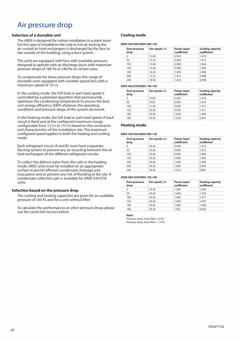
20VDGFF102
Air pressure dropSelection of a ductable unit
The AR05 is designed for indoor installation in a plant room. For this type of installation the cold or hot air leaving the air-cooled air heat exchangers is discharged by the fans to the outside of the building, using a duct system.
The units are equipped with fans with available pressure, designed to operate with air discharge ducts with maximum pressure drops of 180 Pa or 240 Pa on certain sizes.
To compensate for these pressure drops this range of ductable units equipped with variable-speed fans with a maximum speed of 19 r/s.
In the cooling mode, the full-load or part-load speed is controlled by a patented algorithm that permanently optimises the condensing temperature to ensure the best unit energy effi ciency (EER) whatever the operating conditions and pressure drops of the system ductwork.
In the heating mode, the full-load or part-load speed of each circuit is fi xed and at the confi gured maximum (range confi gurable from 12 r/s to 19 r/s) based on the constraints and characteristics of the installation site. The maximum confi gured speed applies to both the heating and cooling mode.
Each refrigerant circuit (A and B) must have a separate ducting system to prevent any air recycling between the air heat exchangers of the diff erent refrigerant circuits.
To collect the defrost water from the coils in the heating mode, AR05 units must be installed on an appropriate surface to permit effi cient condensate drainage and evacuation and to prevent any risk of fl ooding at the site. A condensate collection pan is available for AR05 039-078 units.
Selection based on the pressure drop
The cooling and heating capacities are given for an available pressure of 160 Pa and for a unit without fi lter.
To calculate the performances at other pressure drops please use the correction factors below.
Cooling mode
AR05 039-050/AR05 080-120
Duct pressure
drop
Fan speed, r/s Power input
coeffi cient
Cooling capacity
coeffi cient
0 12.00 0.943 1.01950 13.33 0.962 1.012100 14.66 0.980 1.006130 15.46 0.990 1.003160 16.26 1.000 1.000200 17.31 1.012 0.998240 18.36 1.023 0.996
AR05 060-078/AR05 140-160
Duct pressure
drop
Fan speed, r/s Power input
coeffi cient
Cooling capacity
coeffi cient
0 15.83 0.929 1.01850 16.81 0.944 1.016100 17.78 0.964 1.014130 18.36 0.978 1.011160 18.36 1.000 1.000180 18.36 1.019 0.991
Heating mode
AR05 039-050/AR05 080-120
Duct pressure
drop
Fan speed, r/s Power input
coeffi cient
Heating capacity
coeffi cient
0 18.36 0.990 1.01650 18.36 0.990 1.012100 18.36 0.990 1.009130 18.36 1.000 1.005160 18.36 1.000 1.000200 18.36 1.000 0.994240 18.36 1.010 0.981
AR05 060-078/AR05 140-160
Duct pressure
drop
Fan speed, r/s Power input
coeffi cient
Heating capacity
coeffi cient
0 18.36 1.000 1.02650 18.36 1.000 1.020100 18.36 1.000 1.011130 18.36 1.000 1.007160 18.36 1.000 1.000180 18.36 1.001 0.993
Note:
Pressure drop, clean fi lter = 6 Pa Pressure drop, dirty fi lter = 12 Pa

21VDGFF102
Hydronic module (option 116)This module is equipped with pressure transducers to optimise unit operation at the hydronic level.
The hydronic module option reduces the installation time. The unit is factory-equipped with the main hydronic com-ponents required for the system: screen fi lter, water pump, expansion tank, safety valve and water pressure transducers.
The pressure transducers allow the control system to: - display the available pressure at the unit outlet and the
static system pressure - calculate the instantaneous fl ow rate, using an algorithm
that integrates the unit characteristics - integrate the system and water pump protection devices
(lack of water, water pressure, water fl ow rate etc.)
Physical and electrical data, AR05
AR05- units with hydronic module 039 045 050 060 070 078† 080 090 100 120 140 160
Operating weight*
Single pump (AR05) kg 535 543 569 582 582 590 778 927 935 995 1099 1117Dual pump (AR05) kg 561 569 594 608 608 616 804 972 980 1043 1136 1127Hydronic module
Expansion tank volume l 12 12 12 12 12 12 12 35 35 35 35 35Maximum operating pressure kPa 400 400 400 400 400 400 400 400 400 400 400 400Water fi lter Victaulic screen fi lterLow-pressure single and dual pumps
Water pump Pump, Victaulic screen fi lter, safety valve, expansion tank, purge valves (water and air), pressure sensorsShaft power input kW 0.87 0.87 0.87 0.87 0.87 0.87 0.87 0.87 1.26 1.26 1.90 1.90Power input** kW 1.20 1.20 1.20 1.20 1.20 1.20 1.20 1.20 1.50 1.50 2.30 2.30Nominal operating current draw A 1.9 1.9 1.9 2.0 2.0 2.1 2.1 2.1 2.9 3.0 3.8 4.0Maximum current draw at 400 V*** A 2.3 2.3 2.3 2.3 2.3 2.3 2.3 2.3 3.1 3.1 4.3 4.3High-pressure single and dual pumps
Water pump Pump. Victaulic screen fi lter. safety valve. expansion tank. purge valves (water and air). pressure sensorsShaft power input kW 1.90 1.90 1.90 1.90 1.90 1.90 1.90 1.90 1.90 2.56 2.56 2.56Power input** kW 2.30 2.30 2.30 2.30 2.30 2.30 2.30 2.30 2.30 3.00 3.00 3.00Nominal operating current draw A 3.1 3.2 3.2 3.3 3.3 3.4 3.4 3.5 3.6 5.0 5.1 5.3Maximum current draw at 400 V*** A 4.3 4.3 4.3 4.3 4.3 4.3 4.3 4.3 4.3 5.8 5.8 5.8Water connections (with hydronic module) VictaulicDiameter in 2 2 2 2 2 2 2 2 2 2 2 2Outside diameter mm 60.3 60.3 60.3 60.3 60.3 60.3 60.3 60.3 60.3 60.3 60.3 60.3
* Weight shown is a guideline only. To fi nd out the unit refrigerant charge, please refer to the unit nameplate. ** To obtain the maximum power input of a unit with hydronic module, add the maximum unit power input to the pump power input (**). *** To obtain the maximum current draw of a unit with hydronic module, add the maximum unit current draw to the pump current draw (***). † AR05 only
Several water pump types are available: primary single or dual low-pressure pump or single or dual high-pressure pump.
An automatic pump start-up algorithm protects the heat exchanger and the hydronic module piping against frost down to -10°C outside temperature, if the water heat exchanger frost protection option is installed. If necessary increased frost protection down to -20°C is possible by adding heaters to the hydronic module piping (see option 42).
The hydronic module option is integrated into the unit without increasing its dimensions and saves the space normally used for the water pump.

22VDGFF102
Typical hydronic circuit diagram
Legend
Components of the unit and hydronic module
1 Victaulic screen fi lter2 Expansion tank3 Safety valve4 Available pressure pump Note: x 1 for a single pump, x 2 for a dual pump5 Air purge6 Water drain valve Note: A second valve is located on the heat exchanger leaving piping7 Pressure sensor Note: Gives pump suction pressure information (see installation manual)8 Temperature sensor Note: Gives heat exchanger leaving temperature information (see installation
manual)9 Temperature sensor Note: Gives heat exchanger entering temperature information (see installation
manual)10 Pressure sensor Note: Gives unit leaving pressure information (see installation manual) 11 Check valve Note: x 2 for a dual pump, not provided for a single pump12 Plate heat exchanger13 Water heat exchanger frost protection heater
Installation components
14 Temperature probe well15 Air vent16 Flexible connection17 Shut-off valve18 Screen fi lter (obligatory for a unit without hydronic module)19 Pressure gauge20 Water fl ow control valve Note: Not necessary for a hydronic module with a variable-speed pump21 Charge valve22 Frost protection bypass valve (when shut-off valves [17] are closed during
winter)
Notes:- Units without hydronic module are equipped with a fl ow switch and two
temperature sensors (8 and 9).- The pressure sensors are installed on connections without Schrader valve.- Depressurise and empty the system before any intervention.
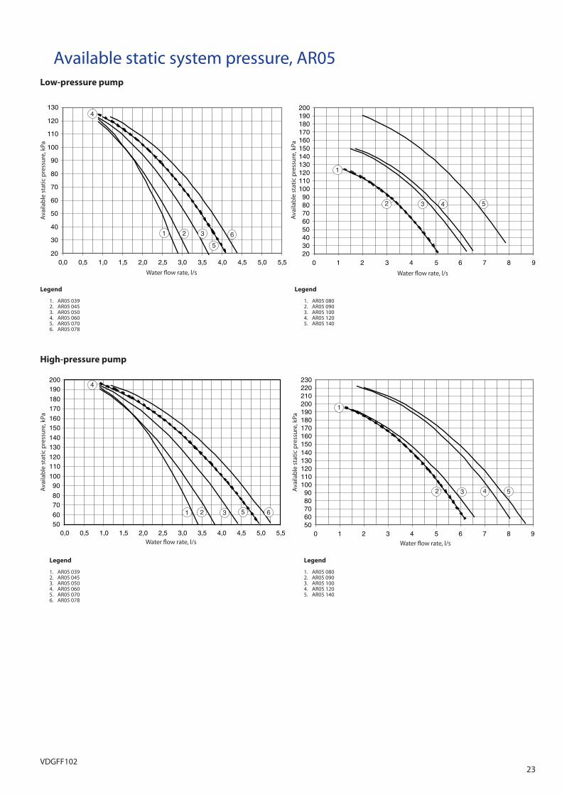
23VDGFF102
Available static system pressure, AR05Low-pressure pump
Water fl ow rate, l/sWater fl ow rate, l/s
Water fl ow rate, l/sWater fl ow rate, l/s
High-pressure pump
2030405060708090
100110120130
0,0 0,5 1,0 1,5 2,0 2,5 3,0 3,5 4,0 4,5 5,0 5,5
65
321
4
2030405060708090
100110120130140150160170180190200
0 1 2 3 4 5 6 7 8 9
1
2 3 4 5
5060708090
100110120130140150160170180190200
0,0 0,5 1,0 1,5 2,0 2,5 3,0 3,5 4,0 4,5 5,0 5,5
4
1 2 3 5 65060708090
100110120130140150160170180190200210220230
0 1 2 3 4 5 6 7 8 9
1
2 3 4 5
Legend
1. AR05 039 2. AR05 045 3. AR05 050 4. AR05 060 5. AR05 070 6. AR05 078
Legend
1. AR05 080 2. AR05 090 3. AR05 100 4. AR05 120 5. AR05 140
Legend
1. AR05 039 2. AR05 045 3. AR05 050 4. AR05 060 5. AR05 070 6. AR05 078
Legend
1. AR05 080 2. AR05 090 3. AR05 100 4. AR05 120 5. AR05 140
Ava
ilab
le s
tatic
pre
ssur
e, k
Pa
Ava
ilab
le s
tatic
pre
ssur
e, k
Pa
Ava
ilab
le s
tatic
pre
ssur
e, k
Pa
Ava
ilab
le s
tatic
pre
ssur
e, k
Pa

24VDGFF102
Variable water flow system (VWF)
Variable water fl ow is a hydronic control function package that permits control of the water fl ow rate.
The VWF not only ensures control at full load, a specifi c algorithm linked to an electronic frequency converter also continuously modulates the fl ow rate to minimise pump consumption at full load as well as part load.
The hydronic module includes pressure transducers that permit intelligent measurement of the water fl ow rate and real-time display on the interface. All adjust-ments can be made directly on the interface, speeding up start-up and maintenance.
As VWF acts directly on the pump, the system no longer requires the control valve at the unit outlet. However, for applications with two-way valves a bypass system must be kept to guarantee the minimum fl ow rate.
Operating logic
• Full-load set pointThe fl ow rate control at full load uses the interface, reducing the pump speed. This fi rst control saves energy that would normally be dissipated in the control valve. For example, if the pressure supplied by the pump is reduced by 20% the power consumption of the pump is reduced by the same ratio, compared to a traditional installation.
• Operating mode at part loadThe control system includes two part-load operating modes:
- Constant outlet pressure control - Constant delta T control.
1 – Constant unit outlet pressure controlThe control continuously acts on the pump speed to ensure a constant outlet pressure.
This solution is suitable for installations with two-way valves. When these close, the water speed will accelerate in the system branches that are still open. For a fi xed-speed pump this results in an unnecessary increase of the pressure at the pump outlet.
The outlet pressure control mode ensures that each circuit branch always has a uniform supply, without unnecessary energy waste.
In industrial processes such as plastic injection moulding, this solution ensures that each terminal unit has the correct pressure supply.
2 – Constant delta T controlThe VWF algorithm maintains a constant delta T no matter what the unit load, reducing the fl ow rate to the minimum.
This solution can be used for systems with two-way or three-way valves and achieves higher energy savings than the “Constant unit outlet pressure control” mode. It is suitable for the majority of comfort applications.
Water fl ow rate, l/sWater fl ow rate, l/s
020406080
100120140160180200220
A
C B
AA
C B
0200400600800
10001200140016001800200022002400
BC
0
BBCC
0 1 2 3 4 5 6 7 8 9 10 11 0 1 2 3 4 5 6 7 8 9 10 11
C B
Energy saving simulation
On the following pages you will fi nd a comparative study of full-load and part-load energy consumption with and without the use of VWF.
Example using model 30RBSY 100 - System with delta T = 5 K - Internal unit pressure drops = 52 kPa - The circuit includes 40 terminal units equipped with valves - Pressure drop, terminal units with valves = 50 kPa - Average pressure drop in the distribution system = 50 kPa - Required system pressure = 100 kPa - Part load = 25% of the valves closed
Pow
er in
put
, kPa
Pres
sure
hea
d, k
Pa
Curves, pump pressure head and power input/water fl ow rate (fi xed speed)
• Full load consumption
1 – Fixed-speed pump (without VWF)In order to settle the system at a correct delta T and fl ow rate at full load, the control valve at the unit outlet must be adjusted to obtain a pressure drop of 32 kPa after the unit. The impact on the energy consumption is not measurable. - A = Ideal operating point - B = Flow rate/pressure without control - C = Flow rate/pressure after control

25VDGFF102
0200400600800
10001200140016001800200022002400
A
50Hz
45Hz
40Hz
35Hz
30Hz
25Hz
AA
50Hz
45Hz
40Hz
35Hz
30Hz
25Hz
46Hz
020406080
100120140160180200220
AAAA
50Hz
45Hz
40Hz35Hz
30Hz25Hz
46Hz
0 1 2 3 4 5 6 7 8 9 10 11 0 1 2 3 4 5 6 7 8 9 10 11
BB
2 – VWF systemThe fl ow rate control uses the interface to modify the rotational speed of the pump. The reduction in consumption is more signifi cant (20%) as both fl ow rate and pressure at the pump outlet are aff ected.
Water fl ow rate, l/sWater fl ow rate, l/sPo
wer
inp
ut, k
Pa
Pres
sure
hea
d, k
Pa
Curves, pump pressure head and power input/water fl ow rate (with VWF)
0200400600800
10001200140016001800200022002400
CD
0
CCDD
020406080
100120140160180200220
CD CCDD
0 1 2 3 4 5 6 7 8 9 10 11 0 1 2 3 4 5 6 7 8 9 10 11
1 – Fixed-speed pump (without VWF)Closing the two-way valves modifi es the system pressure which will in turn aff ect the fl ow rate, but will only reduce the energy consumption of the pump by 3%.
Water fl ow rate, l/sWater fl ow rate, l/s
Pow
er in
put
, kPa
Pres
sure
hea
d, k
Pa
Curves, pump pressure head and power input/water fl ow rate (fi xed speed)
With a three-way valve the variation is not measurable. - C = Flow rate/pressure after control - D = Flow rate/pressure with 25% of the two-way valves
closed.
• Consumption at part load and 25% of the valves closed

26VDGFF102
0200400600800
10001200140016001800200022002400
A
50Hz
45Hz
40Hz
35Hz
30Hz
25Hz
46Hz
A’
45Hz
AA
50Hz
45Hz
40Hz
35Hz
30Hz
25Hz
46Hz
A’A’
45Hz
020406080
100120140160180200220
A
30Hz
A’45Hz AA
50Hz
45Hz
40Hz35Hz
25Hz
46Hz
A’A’
0 1 2 3 4 5 6 7 8 9 10 11 0 1 2 3 4 5 6 7 8 9 10 11
2 – VWF system
Constant unit outlet pressure control mode - A = Flow rate/pressure at full load - A’ = Flow rate/pressure at part load with two-way valves
Water fl ow rate, l/sWater fl ow rate, l/sPo
wer
inp
ut, k
Pa
Pres
sure
hea
d, k
Pa
Curves, pressure head and power input/water fl ow rate, pumps with VWF and constant pressure
Note: Three-way valves have no or little impact on the fl ow rate and the pressure.
020406080
100120140160180200220
A
30Hz
A’'
A’’’
AA
50Hz45Hz
40Hz35Hz
25Hz
46Hz
34Hz
38Hz
A’'A’'
A’’’A’’’
0200400600800
10001200140016001800200022002400
A
50Hz
45Hz
40Hz
35Hz
30Hz
25Hz
46Hz
34Hz
38Hz A’'A’’’
AA
50Hz
45Hz
40Hz
35Hz
30Hz
25Hz
46Hz
34Hz38Hz
A’'A’'A’’’A’’’
0 1 2 3 4 5 6 7 8 9 10 11 0 1 2 3 4 5 6 7 8 9 10 11
Constant delta T control mode - A = Flow rate/pressure at full load - A’’ = Flow rate/pressure at part load with three-way valves - A’’’ = Flow rate/pressure at part load with two-way valves
This solution allows the most signifi cant energy savings, as the VWF continuously acts not only on the fl ow rate, but also on the pressure, both with two-way and three-way valves.
Water fl ow rate, l/sWater fl ow rate, l/s
Pow
er in
put
, kPa
Pres
sure
hea
d, k
Pa
Curves, pressure head and power input/water fl ow rate, pumps with VWF and constant delta T
Energy consumption for this example
30RBSY system with 2-way valves Full load Part load
Fixed speed 1720 W (100%) 1660 W (97%)
VWF system
Pressure control 1380 W (80%) 1250 W (73%)
Delta T control 1380 W (80%) 760 W (44%)
30RBSY system with 3-way valves Full load Part load
Fixed speed 1720 W (100%) 1720 W (100%)
VWF system
Pressure control 1380 W (80%) 1380 W (80%)
Delta T control 1380 W (80%) 580 W (34%)

VVDGFF102