Embed Size (px)
Citation preview

The Vector Control
Vector control technology 1.0 Vector control technology 2.0 Vector control 3.0 A mathematical control method 4.0 Vector control in uninterruptible power supply systems 5.0 Aspects of harmonic management on input and output of three-phase on line ups
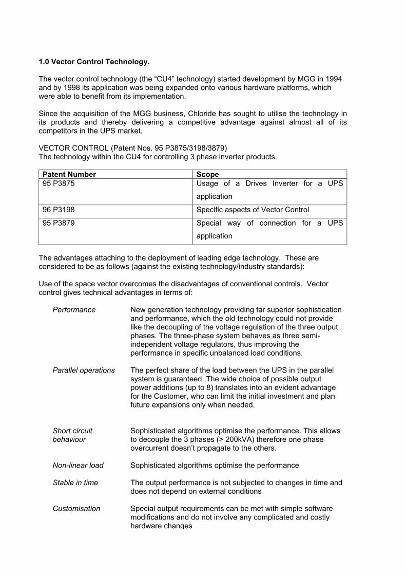
1.0 Vector Control Technology. The vector control technology (the “CU4” technology) started development by MGG in 1994 and by 1998 its application was being expanded onto various hardware platforms, which were able to benefit from its implementation. Since the acquisition of the MGG business, Chloride has sought to utilise the technology in its products and thereby delivering a competitive advantage against almost all of its competitors in the UPS market. VECTOR CONTROL (Patent Nos. 95 P3875/3198/3879) The technology within the CU4 for controlling 3 phase inverter products. Patent Number Scope 95 P3875 Usage of a Drives Inverter for a UPS
application
96 P3198 Specific aspects of Vector Control
95 P3879 Special way of connection for a UPS
application
The advantages attaching to the deployment of leading edge technology. These are considered to be as follows (against the existing technology/industry standards): Use of the space vector overcomes the disadvantages of conventional controls. Vector control gives technical advantages in terms of:
Performance New generation technology providing far superior sophistication and performance, which the old technology could not provide like the decoupling of the voltage regulation of the three output phases. The three-phase system behaves as three semi-independent voltage regulators, thus improving the performance in specific unbalanced load conditions.
Parallel operations The perfect share of the load between the UPS in the parallel system is guaranteed. The wide choice of possible output power additions (up to 8) translates into an evident advantage for the Customer, who can limit the initial investment and plan future expansions only when needed.
Short circuit behaviour
Sophisticated algorithms optimise the performance. This allows to decouple the 3 phases (> 200kVA) therefore one phase overcurrent doesn’t propagate to the others.
Non-linear load Sophisticated algorithms optimise the performance
Stable in time The output performance is not subjected to changes in time and does not depend on external conditions
Customisation Special output requirements can be met with simple software modifications and do not involve any complicated and costly hardware changes
Build quality More robust and reliable, improving longevity
Build Costs Has lower costs of production against previous generation
products
Installation & running cost efficiencies
Quicker installation times and lower servicing and maintenance needs
2.0 Vector Control
Technology
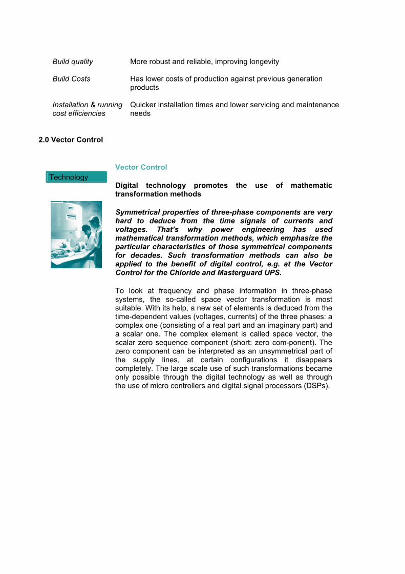
Vector Control
Digital technology promotes the use of mathematic transformation methods
Symmetrical properties of three-phase components are very hard to deduce from the time signals of currents and voltages. That’s why power engineering has used mathematical transformation methods, which emphasize the particular characteristics of those symmetrical components for decades. Such transformation methods can also be applied to the benefit of digital control, e.g. at the Vector Control for the Chloride and Masterguard UPS.
To look at frequency and phase information in three-phase systems, the so-called space vector transformation is most suitable. With its help, a new set of elements is deduced from the time-dependent values (voltages, currents) of the three phases: a complex one (consisting of a real part and an imaginary part) and a scalar one. The complex element is called space vector, the scalar zero sequence component (short: zero com-ponent). The zero component can be interpreted as an unsymmetrical part of the supply lines, at certain configurations it disappears completely. The large scale use of such transformations became only possible through the digital technology as well as through the use of micro controllers and digital signal processors (DSPs).
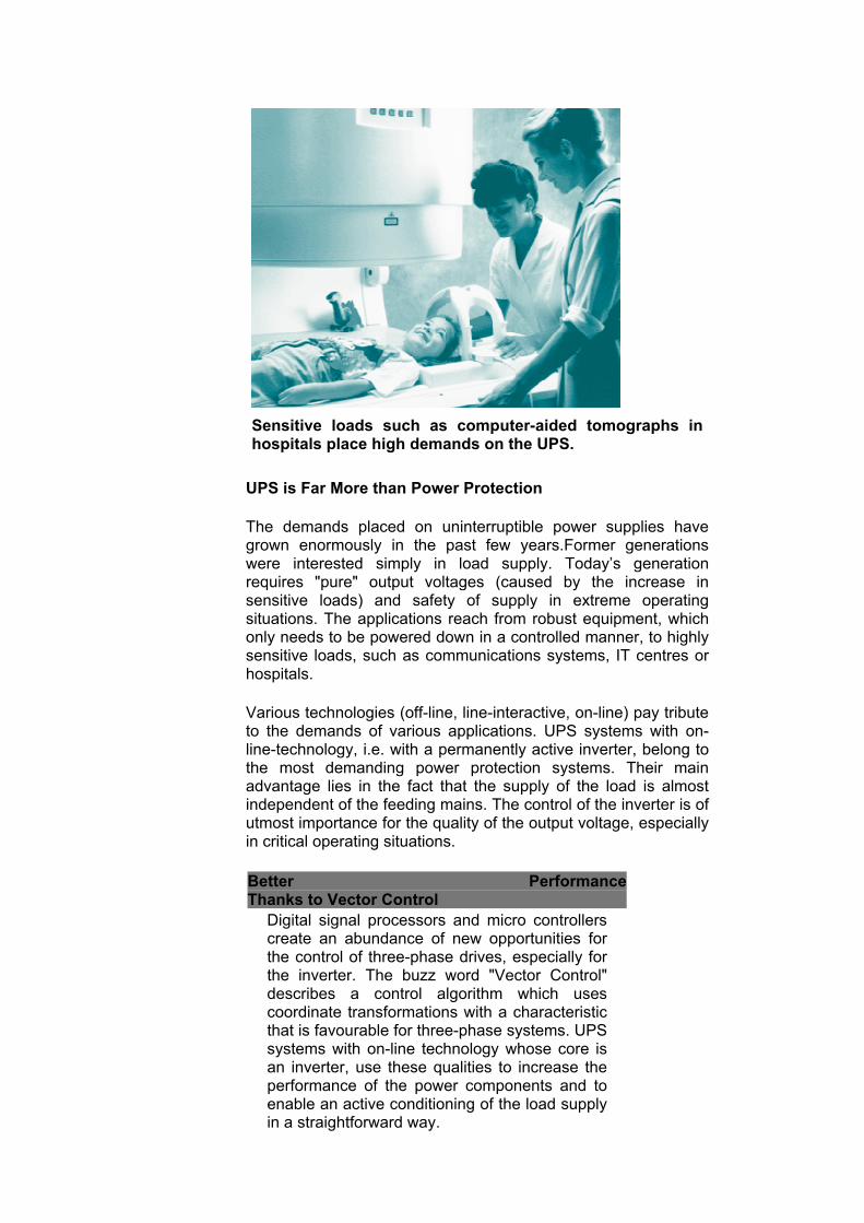
Sensitive loads such as computer-aided tomographs in hospitals place high demands on the UPS.
UPS is Far More than Power Protection
The demands placed on uninterruptible power supplies have grown enormously in the past few years.Former generations were interested simply in load supply. Today’s generation requires "pure" output voltages (caused by the increase in sensitive loads) and safety of supply in extreme operating situations. The applications reach from robust equipment, which only needs to be powered down in a controlled manner, to highly sensitive loads, such as communications systems, IT centres or hospitals.
Various technologies (off-line, line-interactive, on-line) pay tribute to the demands of various applications. UPS systems with on-line-technology, i.e. with a permanently active inverter, belong to the most demanding power protection systems. Their main advantage lies in the fact that the supply of the load is almost independent of the feeding mains. The control of the inverter is of utmost importance for the quality of the output voltage, especially in critical operating situations.
Better Performance Thanks to Vector Control
Digital signal processors and micro controllers create an abundance of new opportunities for the control of three-phase drives, especially for the inverter. The buzz word "Vector Control" describes a control algorithm which uses coordinate transformations with a characteristic that is favourable for three-phase systems. UPS systems with on-line technology whose core is an inverter, use these qualities to increase the performance of the power components and to enable an active conditioning of the load supply in a straightforward way.
UPS systems with double-conversion technology are mainly used for sensitive loads. In this case, it is very important that the power supply can be adapted as close as possible to the safety requirements of the customer, in order to avoid expensive oversized solutions. Especially at high output power systems, flexibility is crucial with the possibility of paralleling the single units. In case of failure of one or several UPS systems, the remaining system can take over the load completely (redundancy).
This fact is useful when planning the appropriate solution for the operating situation. With this type of UPS, although when operated with an existing input mains, the output voltage is still generated by the inverter. Therefore, it is possible to provide the load with almost harmonic-free voltages. This results in a longer life-time of the loads and less strain on the mains supply components. It is these tasks that challenge the inverter control. In the parallel system,balancing currents between the single units must be minimized since these are a strain on the system without being any use. On the other hand, load stepping (as in the case of failure of a parallel unit) must be compensated fast and reliably. The manipulation of harmonics on the output voltage requires an exact analysis of the actual values and consequently a demanding control structure.
UPS and Vector Control
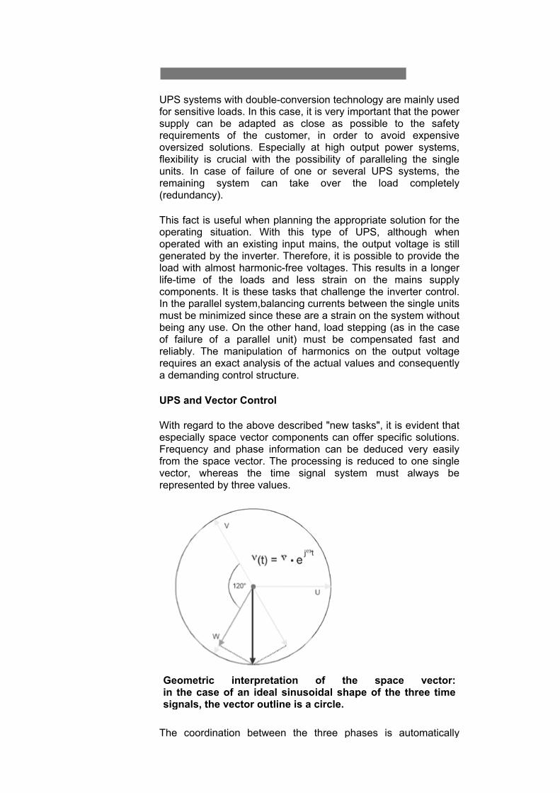
With regard to the above described "new tasks", it is evident that especially space vector components can offer specific solutions. Frequency and phase information can be deduced very easily from the space vector. The processing is reduced to one single vector, whereas the time signal system must always be represented by three values.
Geometric interpretation of the space vector: in the case of an ideal sinusoidal shape of the three time signals, the vector outline is a circle.
The coordination between the three phases is automatically
implied within the space vector. This straightforward control over phasing and frequency of all three phases leads especially with parallel systems or with transient events ( load step output, the load being taken over by feeding mains, switching to battery mode) to minimized balancing currents and hence smooth transitions with no unnecessary strain on the power supply system.
Through the definition of rotating coordinate systems for space vectors, specific harmonic components can be directly selected and "fought" one at a time. This results in low harmonic distortion at the output voltage and a generally load friendly curve shape. The advantage: demanding and time-consuming methods for selecting these components off the time signals are not necessary.
The benefit: higher safety of supply and a higher lifetime of the connected load. Further developments aim at using the power components most efficiently and at guaranteeing an optimum of power protection by the UPS also in critical operating situations.
23.0 A Mathematical control method
Technology
Prof. G. Vaupel
"A Mathematic Control Method"
Professor Dr. Gustav Vaupel has been teaching power engineering at the University of Applied Sciences in Hamburg since 1995. Before that he worked for several years at Siemens in the UPS area among other things. For one of his numerous publications, he received the VDE literature prize of the Energietechnische Gesellschaft (Power Engineering Association) in 1990. Our interview with the acknowledged scientist and industry consultant regarding the complex topic of Vector Control:
Chloride: Mr. Professor Vaupel, what is Vector Control based on, and where is it used?
G.Vaupel:It is actually based on two milestones. First,on the development of the space vector theory, starting 50 years ago as a base for the invention of the control concept with the buzz word "Vector Control". Second, it is based on the invention and further development of micro and signal processors for the digital calculation of coordinate transformations in real-time. Let’s put it this way: Vector Control is a mathematical control method whose processing of measured values and structure is based on the space vector theory. Nowadays, it is not only used for the speed control of three-phase a. c. machines, but also in the electrical power distribution,as well as in power supply systems.
Chloride: Where do you see the advantages, compared to the classic processing of time signals?
G.Vaupel: Space vectors reduce the calculation time for the solution of mathematical problems in three-phase systems andadditionally improve its vividness. Regarding the time characteristics of current and voltage, no restrictions are made, so non-sinusoidal and transient processes are included as well. This is of utmost importance with the "typical" non-linear loads of UPS systems, as for example power supply of information and communications systems. Lab experiments have proved that the application of Vector Control in UPS systems, as opposed to a conventional, phase-related control, especially shows advantages in case of the interaction of the single phases. This normally happens with unsymmetrical and non-linear load of UPS. If phase relations are important as in the parallel mode, a Vector Control has advantages. In this case the Vector Control provides the control unit with information on amplitude, phase and frequency in a very simple manner.
Chloride: Does Vector Control have an influence on the inverter technology in that it makes it more flexible and open to new applications?
G.Vaupel: At its beginning the space vector theory was used as a further mathematical method of coordinate transformationdescribing static and dynamic processes in 3-wire and 4-wire systems. Later on, it developed into the essential mathematicalbase of field-oriented control or Vector Control of a. c. machines. In combination with modern digital technology(which has been speeding up transformation causedmultiplications and computing operations), further applicationsin the distribution and quality of electrical power have come tolife beyond the field of electrical drive technology. The UPSwith its high demands for dynamics, robustness and load-independence needs a control concept like Vector Control forfull use of all advantages of new inverter technology.
Chloride: What are your prospects for the further development in this area?
G.Vaupel: Modern information technology as well as high availability of micro controllers and digital signal processors provide us with the necessary tools to enable us to use the above mentioned advantages even for lower cost products. With the further development of the integration of such flexible processing technologies, ever more complicated growing solutions can be realized. Especially in the UPS area, the development of new mathematical methods sets itself into the main position for the optimal power supply in a wide range of operating situations and automatic adapting to various loads.
4.0 Vector Control in Uninterruptible Power Supply Systems (UPS)
R Huempfner, G Vaupel
0. Introduction
To control the output voltage of uninterruptible power supplies (UPS), instantaneous value related methods are usually used. These are known for their restrictions (determined by the system) at non-linear loads and in parallel operation. To meet the requirements, this basic control concept therefore uses several additional complex components. A mathematical representation specially suitable for calculations in three-wire and four-wire systems is called �space vector�. Such systems often occur in power distribution engineering and drive technology (distribution of electrical energy via three-phase systems, three-phase transformers, three-string synchronous and asynchronous drives). A representation with the help of space vectors allows a straightforward, clear and often illustrative description and calculation of both stationary and dynamic processes in these fields. The space vector transformation is a newer calculation method which has gained importance over the past few years, especially when describing dynamic processes in three-phase a.c. machines. This article is intended to show the advantages of using space vector representation in controlling UPS. The above described disadvantages of conventional controls do not occur when resorting to this approach. 1. Introducing the Terms of Vector Control
1.1. The Space Vector Transformation (SVT)
The SVT describes the coordinate transformation of three time-dependent values. The resulting values consist of a complex element, the so-called space vector and a scalar zero sequence component (short: zero component). The transformation equations are defined as follows:
( ) ( ) ( ) ( )[ ]( ) ( ) ( ) ( )[ ] π
32
2
,31:component zero
32: vectorspace
j
WVUZ
WVU
eawithtvtvtvtv
tvatvatvtv
=++⋅=
⋅+⋅+⋅= (eq. 1-1)
For the representation of the vector-valued space vector we have chosen the preferably used underscore arrows.
To keep the different amplitude values comparable, the signals ( ) ( )tvtv SR , and ( )tvT refer to the maximum value of a sinusoidal signal which has the rms value nomV .
( ) ( )TSRXwith
VtVtv
nom
XX ,,,
2=
⋅= (eq. 1-2)
The spin operator a causes the time signals to be projected onto axes rotated by 120° or
radπ32
respectively.
Introducing the Terms of Vector Control
For the operator, the following relations appliy:
...2,1,0,
013
2
==
=+++ nforaa
aaiin
(eq. 1-3)
The space vector is defined for any time signals. Compared to these when looking at three-phase systems, the space vector transformed values have favourable characteristics. If one assumes for example, purely sinusoidal time signals with the same amplitude and frequency which are phase-shifted by 120° each,
( ) ( ) ( )
( )
( )
⋅+⋅⋅=
+⋅=
⋅+⋅⋅=
−⋅=
+⋅=⋅=
−−
−−
−
tjjtjj
W
tjjtjj
V
tjtjU
eeeevtvtv
eeeevtvtv
eevtvtv
ωπωπ
ωπωπ
ωω
πω
πω
ω
32
32
32
32
21�
32cos�
21�
32cos�
21�cos�
(eq. 1-4)
the following is obtained for the space vector values:
( ) ( ) ( )[ ]( ) ( ) ( )[ ] 011
21�
31
�1121�
32
22
2222
=⋅+++⋅++⋅⋅=
⋅=⋅⋅+⋅++⋅⋅+⋅+⋅⋅=
−
−
tjtjZ
tjtjtj
eaaeaavtv
eveaaaaeaaaavtv
ωω
ωωω
(eq. 1-5)
This shows that the space vector of a symmetrical, ideal sinusoidal three-phase system during one period describes a 360 ° turn with a mathematical positive spin direction, whereas the vector length is constant. The zero component in that case always equals zero.
This symmetrical case in three-phase systems is an ideal state for the use in power engineering. The space vector representation is especially interesting, since in the symmetrical case, the state of the system can be described with a single (complex) value. Thus, three-phase relations can be represented in a well structured manner by means of single-phase equivalent circuit diagrams. The space vector system contains complex value voltages and currents, whereas the zero system contains scalar ones. If the voltages are no longer purely sinusoidal, but contain harmonic components of higher order, they can affect the space vector as well as the zero system. In the following we will be discussing which important harmonics affect which part of the space vector components. 1.2. Zero Components in the Three-phase Systems
It depends first of all on the topology of the system used, if a zero component exists at all. When for example, one looks at the line currents in the three-wire system, the following condition must apply:
( ) ( ) ( ) 0=++ tititi TSR (eq. 1-6)
Introducing the Terms of Vector Control
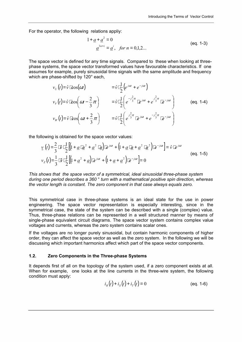
This means that the zero component of the currents space vectors in this case always equals zero. The above condition can also be valid in a system with a neutral line (four-wire system), if the strain on the individual wires is symmetrical. Thus, the zero component is often called the unsymmetrical part of the space vectors. But, with symmetrical strain in the four-wire system, currents can also occur in the neutral line which are caused by harmonic components on the fundamental frequency current. Some of these currents usually occur in the zero system. Figure 1 shows the overlaying of the harmonic current components at the neutral line in a four-wire system, depending on the order. It is assumed that the harmonic has, in relation to its fundamental mode, the same phasing in all three time signals. (This is usually true in practice.) One can recognize that only the multiples of three (3., 6., 9., etc.) provide values that are different from zero. Therefore it can be noted that besides the unsymmetrical harmonic components, usually harmonics with an ordinal number being a multiple of three occur at the zero component. 1.3. Harmonic Components in the Space Vector
It is easy to see from the last paragraph that the space vector value (besides the symmetrical harmonic components of the three-phase system) contains those harmonics that are not a multiple of three (also assuming that the harmonic components have, in relation to their fundamental mode, the same phasing in all three phases).
Figure 2 shows a simulation of a six-pulse current space vector which contains harmonic components of the 5th and 7th harmonic. The locus has a typical hexagonal shape.
Figure 1: Influence of the order of higher harmonics on the zero system in three-phase systems
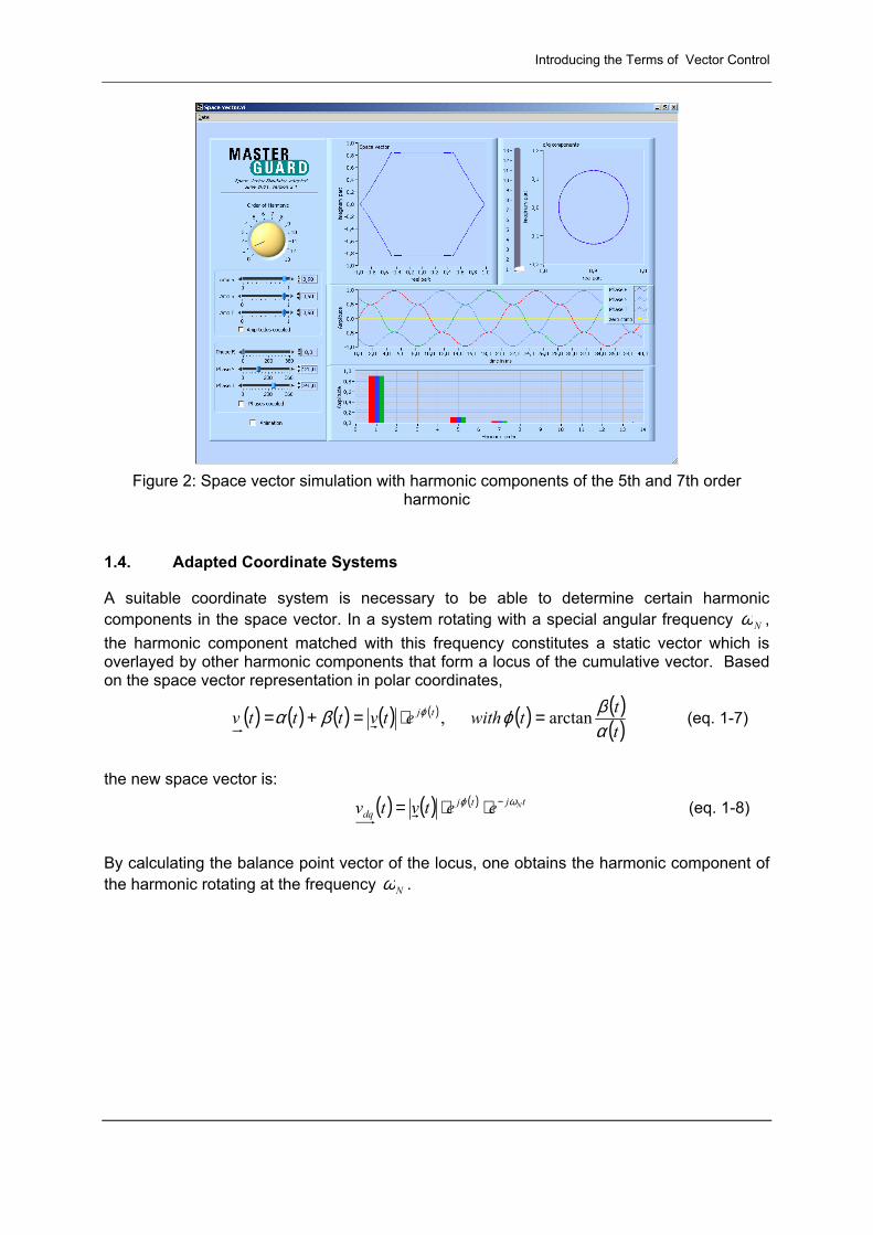
Introducing the Terms of Vector Control
Figure 2: Space vector simulation with harmonic components of the 5th and 7th order
harmonic
1.4. Adapted Coordinate Systems
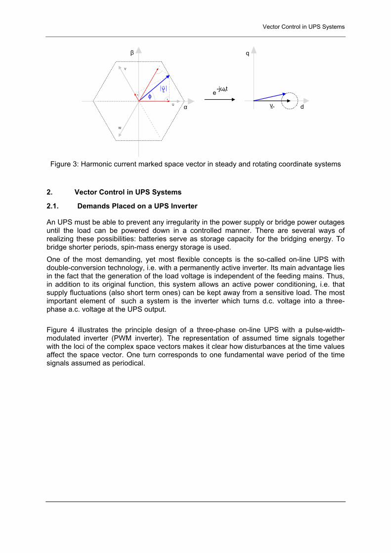
A suitable coordinate system is necessary to be able to determine certain harmonic components in the space vector. In a system rotating with a special angular frequency Nω , the harmonic component matched with this frequency constitutes a static vector which is overlayed by other harmonic components that form a locus of the cumulative vector. Based on the space vector representation in polar coordinates,
( ) ( ) ( ) ( ) ( ) ( ) ( )( )tttwithetvtttv tj
αβϕβα ϕ arctan, =⋅=+= (eq. 1-7)
the new space vector is:
( ) ( ) ( ) tjtjdq
Neetvtv ωϕ −⋅⋅= (eq. 1-8)
By calculating the balance point vector of the locus, one obtains the harmonic component of the harmonic rotating at the frequency Nω .
Vector Control in UPS Systems
α
β
ϕν
U
V
W
d
e-jω tN
νN
q
Figure 3: Harmonic current marked space vector in steady and rotating coordinate systems
2. Vector Control in UPS Systems
2.1. Demands Placed on a UPS Inverter
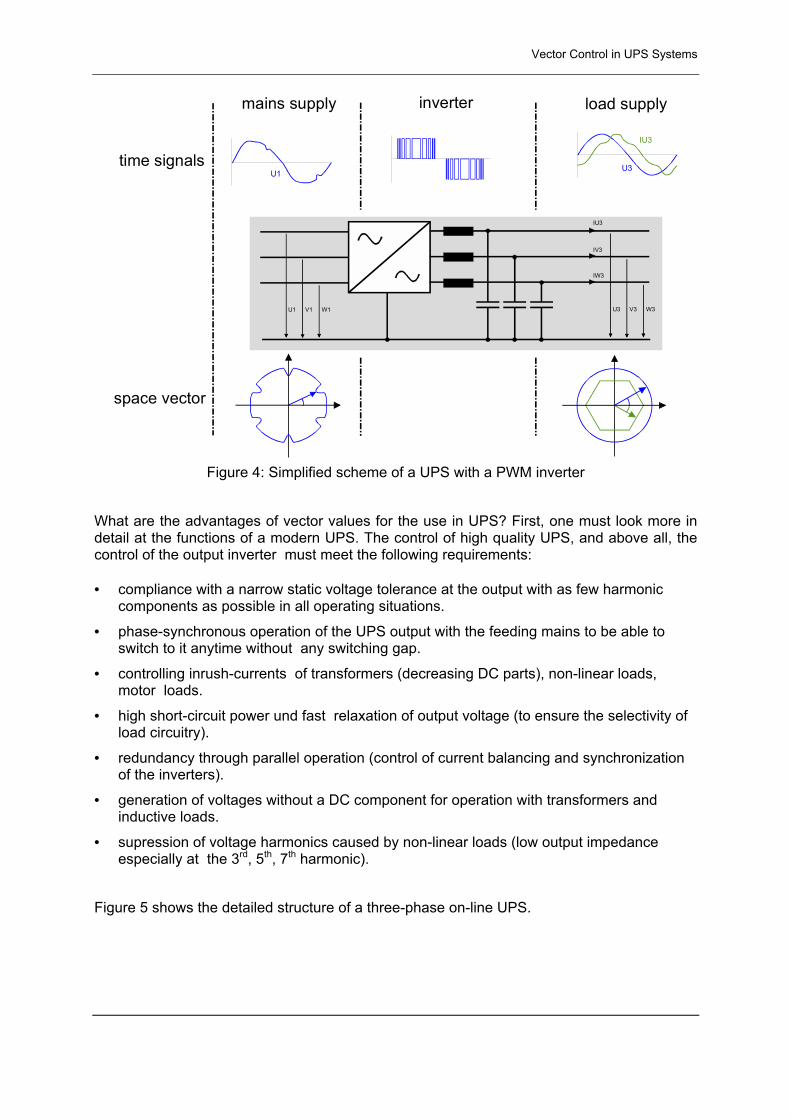
An UPS must be able to prevent any irregularity in the power supply or bridge power outages until the load can be powered down in a controlled manner. There are several ways of realizing these possibilities: batteries serve as storage capacity for the bridging energy. To bridge shorter periods, spin-mass energy storage is used. One of the most demanding, yet most flexible concepts is the so-called on-line UPS with double-conversion technology, i.e. with a permanently active inverter. Its main advantage lies in the fact that the generation of the load voltage is independent of the feeding mains. Thus, in addition to its original function, this system allows an active power conditioning, i.e. that supply fluctuations (also short term ones) can be kept away from a sensitive load. The most important element of such a system is the inverter which turns d.c. voltage into a three-phase a.c. voltage at the UPS output. Figure 4 illustrates the principle design of a three-phase on-line UPS with a pulse-width- modulated inverter (PWM inverter). The representation of assumed time signals together with the loci of the complex space vectors makes it clear how disturbances at the time values affect the space vector. One turn corresponds to one fundamental wave period of the time signals assumed as periodical.
Vector Control in UPS Systems
U3 V3 W3
IU3
IV3
IW3
time signals
space vector
U3
IU3
mains supply inverter load supply
U1 V1 W1
U1
Figure 4: Simplified scheme of a UPS with a PWM inverter
What are the advantages of vector values for the use in UPS? First, one must look more in detail at the functions of a modern UPS. The control of high quality UPS, and above all, the control of the output inverter must meet the following requirements: • compliance with a narrow static voltage tolerance at the output with as few harmonic
components as possible in all operating situations.
• phase-synchronous operation of the UPS output with the feeding mains to be able to switch to it anytime without any switching gap.
• controlling inrush-currents of transformers (decreasing DC parts), non-linear loads, motor loads.
• high short-circuit power und fast relaxation of output voltage (to ensure the selectivity of load circuitry).
• redundancy through parallel operation (control of current balancing and synchronization of the inverters).
• generation of voltages without a DC component for operation with transformers and inductive loads.
• supression of voltage harmonics caused by non-linear loads (low output impedance especially at the 3rd, 5th, 7th harmonic).
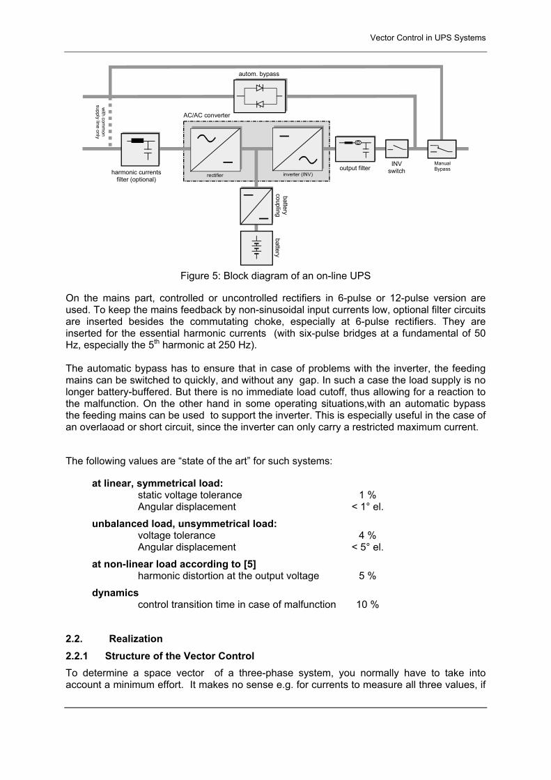
Figure 5 shows the detailed structure of a three-phase on-line UPS.
Vector Control in UPS Systems
harmonic currentsfilter (optional)
rectifier inverter (INV)
batterycoupling
battery
ManualBypass
autom. bypass
with com
mon
supply line only
AC/AC converter
output filterINV
switch
Figure 5: Block diagram of an on-line UPS
On the mains part, controlled or uncontrolled rectifiers in 6-pulse or 12-pulse version are used. To keep the mains feedback by non-sinusoidal input currents low, optional filter circuits are inserted besides the commutating choke, especially at 6-pulse rectifiers. They are inserted for the essential harmonic currents (with six-pulse bridges at a fundamental of 50 Hz, especially the 5th harmonic at 250 Hz). The automatic bypass has to ensure that in case of problems with the inverter, the feeding mains can be switched to quickly, and without any gap. In such a case the load supply is no longer battery-buffered. But there is no immediate load cutoff, thus allowing for a reaction to the malfunction. On the other hand in some operating situations,with an automatic bypass the feeding mains can be used to support the inverter. This is especially useful in the case of an overlaoad or short circuit, since the inverter can only carry a restricted maximum current.
The following values are �state of the art� for such systems:
at linear, symmetrical load: static voltage tolerance 1 % Angular displacement < 1° el. unbalanced load, unsymmetrical load: voltage tolerance 4 % Angular displacement < 5° el. at non-linear load according to [5] harmonic distortion at the output voltage 5 % dynamics control transition time in case of malfunction 10 % 2.2. Realization 2.2.1 Structure of the Vector Control To determine a space vector of a three-phase system, you normally have to take into account a minimum effort. It makes no sense e.g. for currents to measure all three values, if
Vector Control in UPS Systems
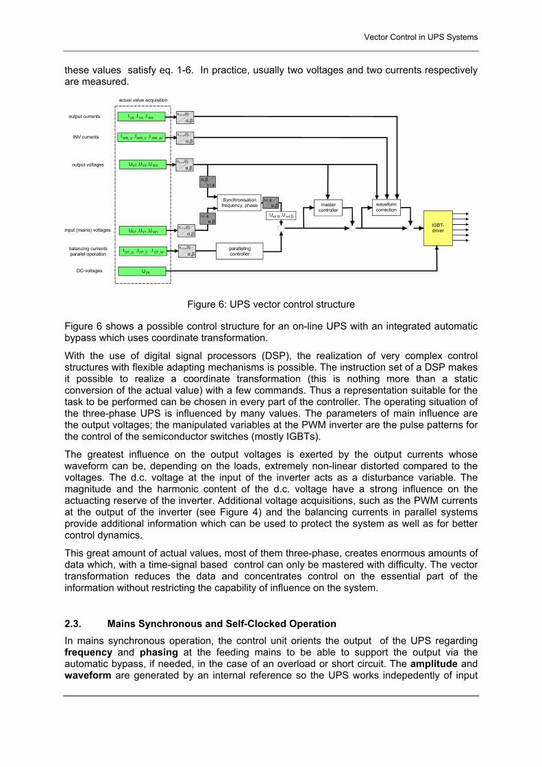
these values satisfy eq. 1-6. In practice, usually two voltages and two currents respectively are measured.
actual value acquisition
U ,U ,UU1 V1 W1
U ,U ,UU3 V3 W3
I ,I ,IWR_U WR_V WR_W
I ,I ,IDT_U DT_V DT_Wparallelingcontroller
Synchronisationfrequency, phase waveform
correction
IGBT-driver
UZK
α,β
α,βv (t)U,V,W
α,βv (t)U,V,W
α,βv (t)U,V,W
α,βν ,ϕ
ν ,ϕ
U ,Uref α ref β
α,βν ,ϕ
α,βv (t)U,V,W
I ,I ,IU3 V3 W3α,β
v (t)U,V,W
mastercontroller
output currents
INV currents
output voltages
input (mains) voltages
balancing currentsparallel operation
DC-voltages
Figure 6: UPS vector control structure
Figure 6 shows a possible control structure for an on-line UPS with an integrated automatic bypass which uses coordinate transformation.
With the use of digital signal processors (DSP), the realization of very complex control structures with flexible adapting mechanisms is possible. The instruction set of a DSP makes it possible to realize a coordinate transformation (this is nothing more than a static conversion of the actual value) with a few commands. Thus a representation suitable for the task to be performed can be chosen in every part of the controller. The operating situation of the three-phase UPS is influenced by many values. The parameters of main influence are the output voltages; the manipulated variables at the PWM inverter are the pulse patterns for the control of the semiconductor switches (mostly IGBTs).
The greatest influence on the output voltages is exerted by the output currents whose waveform can be, depending on the loads, extremely non-linear distorted compared to the voltages. The d.c. voltage at the input of the inverter acts as a disturbance variable. The magnitude and the harmonic content of the d.c. voltage have a strong influence on the actuacting reserve of the inverter. Additional voltage acquisitions, such as the PWM currents at the output of the inverter (see Figure 4) and the balancing currents in parallel systems provide additional information which can be used to protect the system as well as for better control dynamics.
This great amount of actual values, most of them three-phase, creates enormous amounts of data which, with a time-signal based control can only be mastered with difficulty. The vector transformation reduces the data and concentrates control on the essential part of the information without restricting the capability of influence on the system.
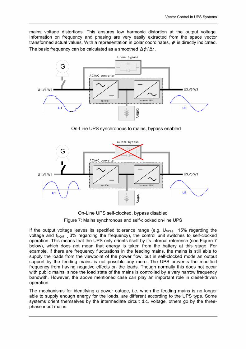
2.3. Mains Synchronous and Self-Clocked Operation In mains synchronous operation, the control unit orients the output of the UPS regarding frequency and phasing at the feeding mains to be able to support the output via the automatic bypass, if needed, in the case of an overload or short circuit. The amplitude and waveform are generated by an internal reference so the UPS works indepedently of input
Vector Control in UPS Systems
mains voltage distortions. This ensures low harmonic distortion at the output voltage. Information on frequency and phasing are very easily extracted from the space vector transformed actual values. With a representation in polar coordinates, ϕ is directly indicated. The basic frequency can be calculated as a smoothed t∆∆ /ϕ .
rectifie r inverte r (IN V )
G
U1,V1,W1 U3,V3,W3
U3U1
On-Line UPS synchronous to mains, bypass enabled
rectifie r inverte r (IN V )
G
U1,V1,W1 U3,V3,W3
U1 U3
On-Line UPS self-clocked, bypass disabled
autom . bypass
autom . bypass
batterybattery
AC/AC converter
AC/AC converter
Figure 7: Mains synchronous and self-clocked on-line UPS
If the output voltage leaves its specified tolerance range (e.g. UNOM �15% regarding the voltage and fNOM� 3% regarding the frequency), the control unit switches to self-clocked operation. This means that the UPS only orients itself by its internal reference (see Figure 7 below), which does not mean that energy is taken from the battery at this stage. For example, if there are frequency fluctuations in the feeding mains, the mains is still able to supply the loads from the viewpoint of the power flow, but in self-clocked mode an output support by the feeding mains is not possible any more. The UPS prevents the modified frequency from having negative effects on the loads. Though normally this does not occur with public mains, since the load state of the mains is controlled by a very narrow frequency bandwith. However, the above mentioned case can play an important role in diesel-driven operation.
The mechanisms for identifying a power outage, i.e. when the feeding mains is no longer able to supply enough energy for the loads, are different according to the UPS type. Some systems orient themselves by the intermediate circuit d.c. voltage, others go by the three-phase input mains.
Vector Control in UPS Systems
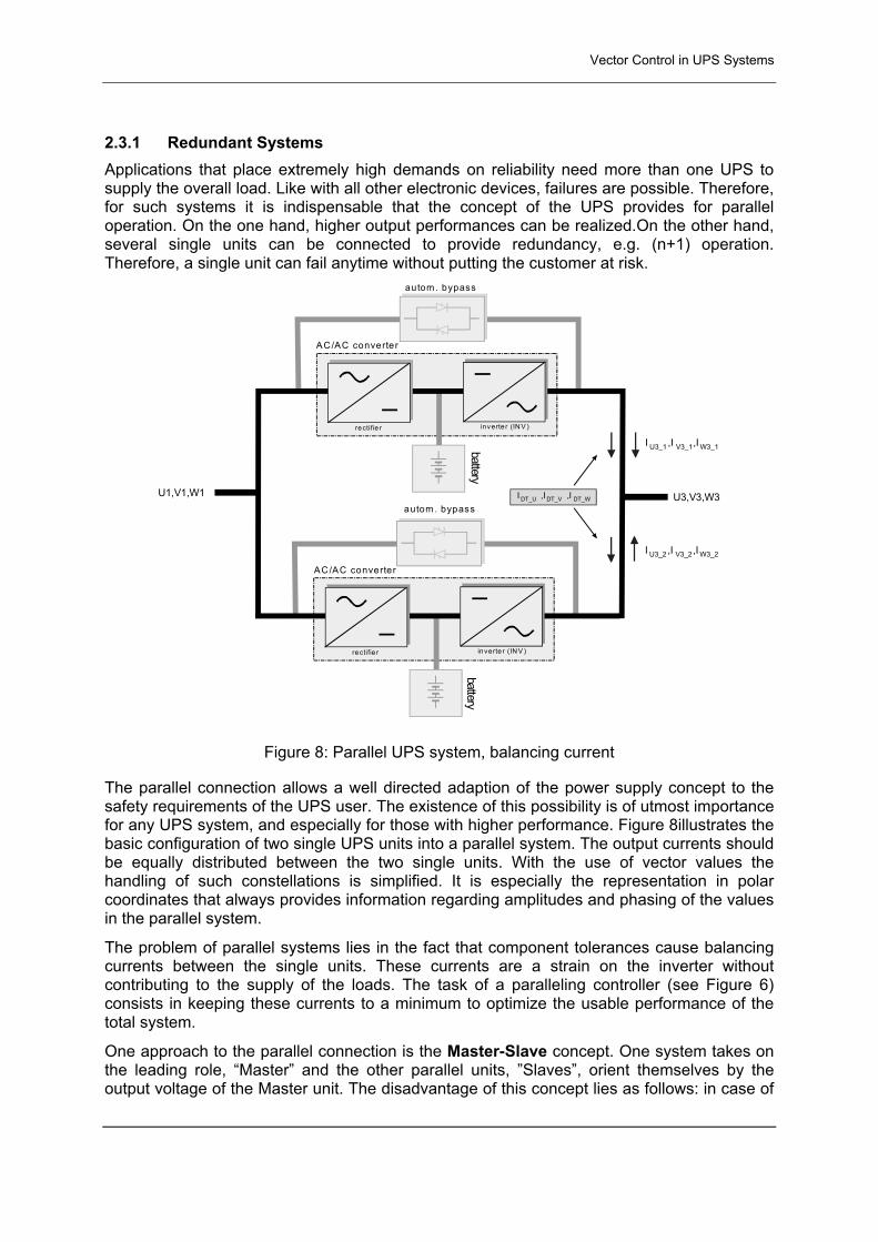
2.3.1 Redundant Systems Applications that place extremely high demands on reliability need more than one UPS to supply the overall load. Like with all other electronic devices, failures are possible. Therefore, for such systems it is indispensable that the concept of the UPS provides for parallel operation. On the one hand, higher output performances can be realized.On the other hand, several single units can be connected to provide redundancy, e.g. (n+1) operation. Therefore, a single unit can fail anytime without putting the customer at risk.
rectifie r inverte r (IN V )
battery
au tom . bypass
AC/AC converter
U1,V1,W1
rectifie r inverte r (IN V )
AC/AC converter
U3,V3,W3
I ,I ,IU3_1 V3_1 W3_1
I ,I ,IU3_2 V3_2 W3_2
I ,I ,IDT_U DT_V DT_W
battery
autom . bypass
Figure 8: Parallel UPS system, balancing current
The parallel connection allows a well directed adaption of the power supply concept to the safety requirements of the UPS user. The existence of this possibility is of utmost importance for any UPS system, and especially for those with higher performance. Figure 8illustrates the basic configuration of two single UPS units into a parallel system. The output currents should be equally distributed between the two single units. With the use of vector values the handling of such constellations is simplified. It is especially the representation in polar coordinates that always provides information regarding amplitudes and phasing of the values in the parallel system.
The problem of parallel systems lies in the fact that component tolerances cause balancing currents between the single units. These currents are a strain on the inverter without contributing to the supply of the loads. The task of a paralleling controller (see Figure 6) consists in keeping these currents to a minimum to optimize the usable performance of the total system.
One approach to the parallel connection is the Master-Slave concept. One system takes on the leading role, �Master� and the other parallel units, �Slaves�, orient themselves by the output voltage of the Master unit. The disadvantage of this concept lies as follows: in case of
Measurements and Comparison of Different Control Concepts
the failure of the Master unit, the system becomes �leaderless�, for example, load changes (as they can occur with the failure of the unit, too) can result in a load cutoff.
By means of the Vector Control a paralleling concepts can be realized, where each unit has the same status in the UPS system: when being hooked up, the single units can be led to steady phase relations (synchronous operation), at which a simultaneous start of the single blocks on the secure bus is possible, any unit being able to continue running smoothly in case of failure. Additionally, by precisely setting the manipulated vectors of every inverter, the balancing currents can be minimized and the strain on the output of the parallel system can be reduced. This solution requires straightforward communication between the single units.
2.3.2 Waveform Correction The value set by the master controller (see Figure 6), is determined by an internal reference signal (mains synchronous or self-clocked). Parallel systems additionally have to refer to thebalancing currents. The design of this controller is most important for the dynamics of the total system. Additional modules described as a waveform correction in Figure 6, ensure low output harmonic distortion in stationary operation. These modules work dynamically with higher time constants than the master controller to prevent any influence on the stability of the control unit. The waveform of the set value is influenced in these modules. By knowing the controlled system at the UPS output (neutral grounding transformer, PMW switching frequency filter), the pulse pattern of the semiconductor can be influenced to keep harmonic distortion low. Possible functions are: ! influencing certain harmonic components. By changing the coordinate
system, the harmonic components can be easily identified off the space vector components (e.g. 3rd, 5th, 7th harmonic).
! realizing flexible control systems for high stability and accuracy (e.g. state regulator, adaptive regulators).
The waveform correction can be undertaken according to various criteria. Its structure is more complex than that of the master controller, but the manner of the correction has enormous effects on the harmonic content of the output voltage.
3. Measurements and Comparison of Different Control Concepts
The direct comparison of UPS systems with or without Vector Control shows the advantages of the presented concept compared to the conventional three-phase control. The measuring was done during stationary operation with special load situations:
! linear unsymmetrical load ! non-linear load (according to [5], appendix M.5)
For the measurements, UPS systems with the same nominal power (20 kVA at a performance factor of 0,8 inductive) and comparable application areas were used.
Measurements and Comparison of Different Control Concepts
3.1. Definition of THD (the value to describe the quality of electrical power) A harmonic analysis (Fourier transformation) is used for the quantitative description of electrical power quality. As a function of time, a non-sinusoidal Fourier series can be written as follows (applies to the current similarily):
( )nn
n tnvtvVtv ϕωω +⋅⋅∧
+⋅∧
+= ∑∞
= sin sin)(
210 (eq. 3-1)
where fundamental wave tvv sin11 ω⋅∧
= angular frequency f⋅⋅= πω 2 d.c.component 0V , arithmetic mean ordinal number n . The quality of electrical power is internationally judged by the value THD (total harmonic distortion factor) of the voltage and the current respectively. The THD value is defined by, /7/:
1
50
2
2
V
VTHD n
n∑== (eq. 3-2)
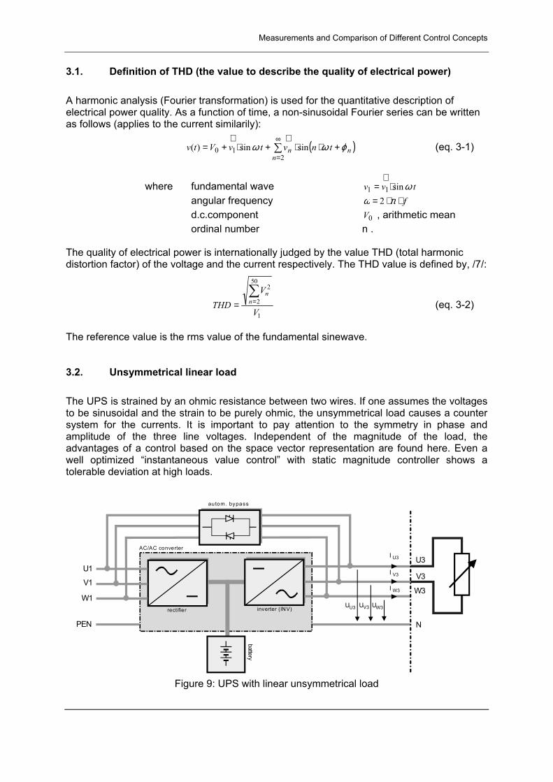
The reference value is the rms value of the fundamental sinewave. 3.2. Unsymmetrical linear load The UPS is strained by an ohmic resistance between two wires. If one assumes the voltages to be sinusoidal and the strain to be purely ohmic, the unsymmetrical load causes a counter system for the currents. It is important to pay attention to the symmetry in phase and amplitude of the three line voltages. Independent of the magnitude of the load, the advantages of a control based on the space vector representation are found here. Even a well optimized �instantaneous value control� with static magnitude controller shows a tolerable deviation at high loads.
rectifier inverter (INV)
battery
au tom. bypass
AC/AC converter
U1
V1
W1
PEN
U3U V3U W3U
U3I
V3I
W3I
N
U3
V3
W3
Figure 9: UPS with linear unsymmetrical load
Measurements and Comparison of Different Control Concepts
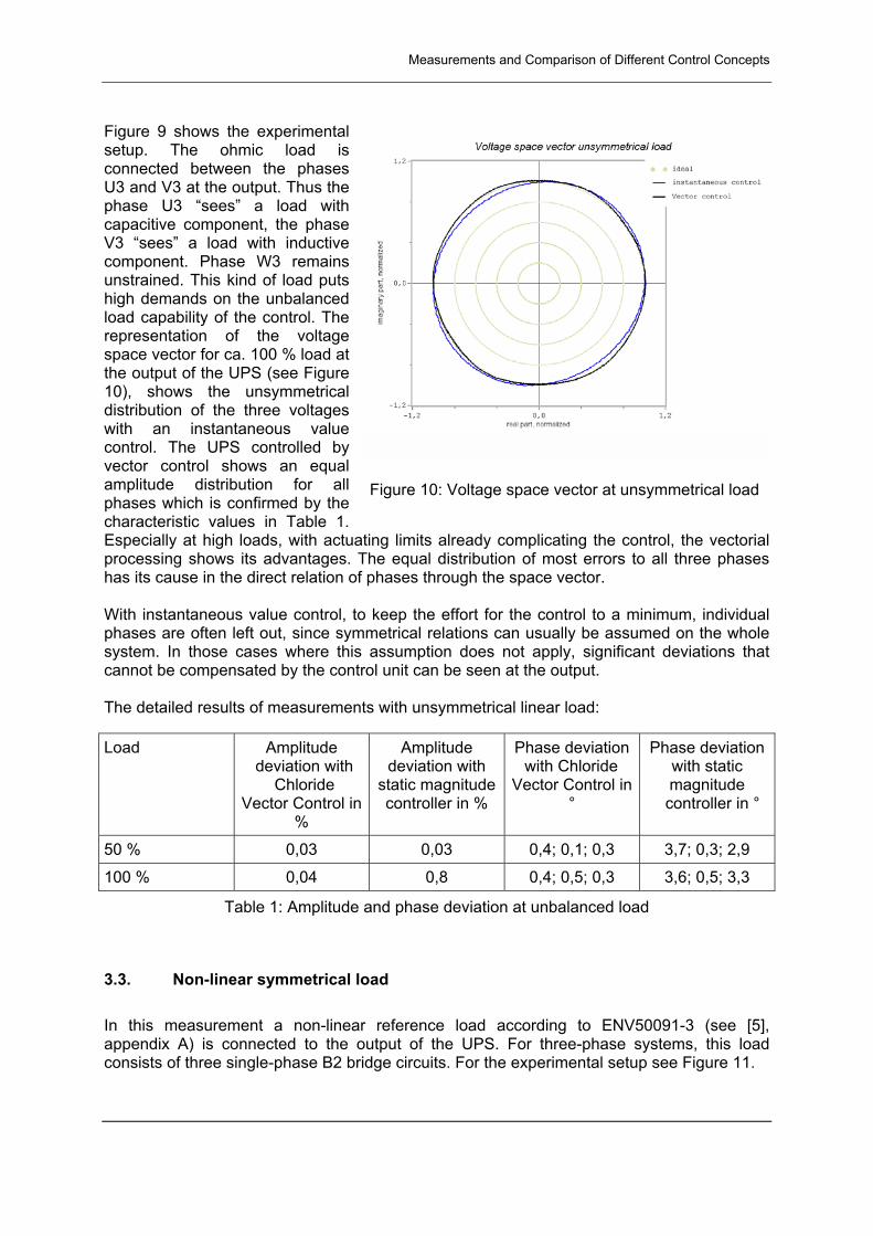
Figure 9 shows the experimental setup. The ohmic load is connected between the phases U3 and V3 at the output. Thus the phase U3 �sees� a load with capacitive component, the phase V3 �sees� a load with inductive component. Phase W3 remains unstrained. This kind of load puts high demands on the unbalanced load capability of the control. The representation of the voltage space vector for ca. 100 % load at the output of the UPS (see Figure 10), shows the unsymmetrical distribution of the three voltages with an instantaneous value control. The UPS controlled by vector control shows an equal amplitude distribution for all phases which is confirmed by the characteristic values in Table 1. Especially at high loads, with actuating limits already complicating the control, the vectorial processing shows its advantages. The equal distribution of most errors to all three phases has its cause in the direct relation of phases through the space vector. With instantaneous value control, to keep the effort for the control to a minimum, individual phases are often left out, since symmetrical relations can usually be assumed on the whole system. In those cases where this assumption does not apply, significant deviations that cannot be compensated by the control unit can be seen at the output. The detailed results of measurements with unsymmetrical linear load:
Load Amplitude deviation with
ChlorideVector Control in
%
Amplitude deviation with
static magnitude controller in %
Phase deviation with Chloride
Vector Control in °
Phase deviation with static magnitude controller in °
50 % 0,03 0,03 0,4; 0,1; 0,3 3,7; 0,3; 2,9
100 % 0,04 0,8 0,4; 0,5; 0,3 3,6; 0,5; 3,3
Table 1: Amplitude and phase deviation at unbalanced load
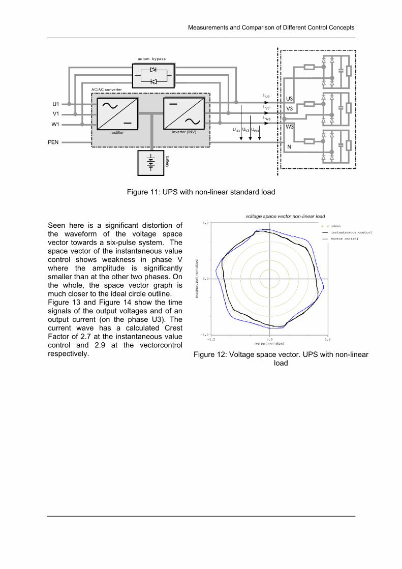
3.3. Non-linear symmetrical load In this measurement a non-linear reference load according to ENV50091-3 (see [5], appendix A) is connected to the output of the UPS. For three-phase systems, this load consists of three single-phase B2 bridge circuits. For the experimental setup see Figure 11.
Figure 10: Voltage space vector at unsymmetrical load
Measurements and Comparison of Different Control Concepts
rectifier inverter (INV)
battery
au tom. bypass
AC/AC converter
U1
V1
W1
PEN
U3U V3U W3U
U3I
V3I
W3I
U3
V3
W3
N
Figure 11: UPS with non-linear standard load
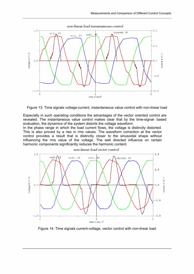
Seen here is a significant distortion of the waveform of the voltage space vector towards a six-pulse system. The space vector of the instantaneous value control shows weakness in phase V where the amplitude is significantly smaller than at the other two phases. On the whole, the space vector graph is much closer to the ideal circle outline. Figure 13 and Figure 14 show the time signals of the output voltages and of an output current (on the phase U3). The current wave has a calculated Crest Factor of 2.7 at the instantaneous value control and 2.9 at the vectorcontrol respectively. Figure 12: Voltage space vector. UPS with non-linear
load
Measurements and Comparison of Different Control Concepts
Figure 13: Time signals voltage-current, instantaneous value control with non-linear load
Especially in such operating conditions the advantages of the vector oriented control are revealed. The instantaneous value control makes clear that by the time-signal- based evaluation, the dynamics of the system distorts the voltage waveform. In the phase range in which the load current flows, the voltage is distinctly distorted. This is also proved by a rise in rms values. The waveform correction at the vector control provides a result that is distinctly closer to the sinusoidal shape without influencing the rms value of the voltage. The well directed influence on certain harmonic components significantly reduces the harmonic content.
Figure 14: Time signals current-voltage, vector control with non-linear load
Summary and Outlook
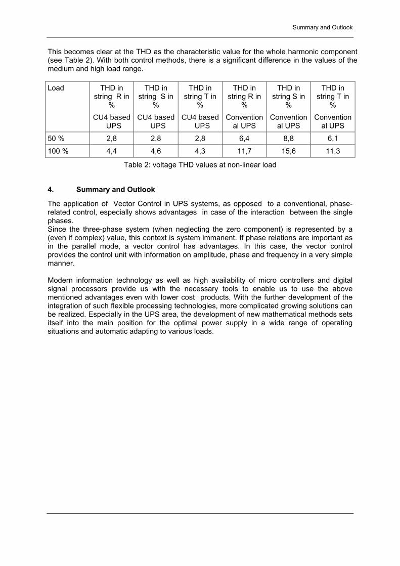
This becomes clear at the THD as the characteristic value for the whole harmonic component (see Table 2). With both control methods, there is a significant difference in the values of the medium and high load range. Load THD in
string R in %
CU4 basedUPS
THD in string S in
% CU4 based
UPS
THD in string T in
% CU4 based
UPS
THD in string R in
% Convention
al UPS
THD in string S in
% Convention
al UPS
THD in string T in
% Convention
al UPS
50 % 2,8 2,8 2,8 6,4 8,8 6,1
100 % 4,4 4,6 4,3 11,7 15,6 11,3
Table 2: voltage THD values at non-linear load
4. Summary and Outlook
The application of Vector Control in UPS systems, as opposed to a conventional, phase-related control, especially shows advantages in case of the interaction between the single phases. Since the three-phase system (when neglecting the zero component) is represented by a (even if complex) value, this context is system immanent. If phase relations are important as in the parallel mode, a vector control has advantages. In this case, the vector control provides the control unit with information on amplitude, phase and frequency in a very simple manner. Modern information technology as well as high availability of micro controllers and digital signal processors provide us with the necessary tools to enable us to use the above mentioned advantages even with lower cost products. With the further development of the integration of such flexible processing technologies, more complicated growing solutions can be realized. Especially in the UPS area, the development of new mathematical methods sets itself into the main position for the optimal power supply in a wide range of operating situations and automatic adapting to various loads.
Bibliography
Figures und Tables Figure 1: Influence of the order of higher harmonics on the zero system in three-phase
systems ................................................................................................................... 3 Figure 2: Space vector simulation with harmonic components of the 5th and 7th order
harmonic.................................................................................................................. 4 Figure 3: Harmonic current marked space vector in steady and rotating coordinate systems 5 Figure 4: Simplified scheme of a UPS with a PWM inverter.................................................... 6 Figure 5: Block diagram of an on-line UPS.............................................................................. 7 Figure 6: UPS vector control structure..................................................................................... 8 Figure 7: Mains synchronous and self-clocked on-line UPS ................................................... 9 Figure 8: Parallel UPS system, balancing current ................................................................. 10 Figure 9: UPS with linear unsymmetrical load....................................................................... 12 Figure 10: Voltage space vector at unsymmetrical load ........................................................ 13 Figure 11: UPS with non-linear standard load ....................................................................... 14 Figure 12: Voltage space vector. UPS with non-linear load .................................................. 14 Figure 13: Time signals voltage-current, instantaneous value control with non-linear load .. 15 Figure 14: Time signals current-voltage, vector control with non-linear load......................... 15 Table 1: Amplitude and phase deviation at unbalanced load ................................................ 13 Table 2: voltage THD values at non-linear load..................................................................... 16
5. Bibliography
[1] Depenbrock, M.; Staudt, V.: Hyper Space Vectors: A New Four-Quantity-Extension of Space Vector Theory, 4th Int. Workshop on Power Def. and Meas. under Nonsinusoidal Cond., Milano, 1997, pp.1-7
[2] V. Staudt, Ruhr-Universität Bochum, Lehrstuhl für Erzeugung und Anwendungen. Energie: "Raumzeiger" 2
[3] V. Staudt, Ein Beitrag zu Leistungsbegriffen und Kompensationsverfahren für Mehrleitersysteme, Fortschritt-Berichte VDI, Reihe 21, Nr. 291, Bochum, 1998
[4] Kovacs, K. P.; Racz, I.: Transiente Vorgänge in Wechselstrommaschinen, Verlag der Ungarischen Akademie der Wissenschaften, Budapest, 1959
[5] DD ENV50091-3:1999; Unterbrechungsfreie Stromversorgungen. Teil 3: Betriebsanforderungen und Prüfverfahren
[6] Hümpfner, Vaupel: "Aspects of harmonic management on in- and output of three-phase on-line-ups�, 7th European Conference on Power Electronics and Applicatons (epe), Sept. 1997, Trondheim, S. 34 � 38 (late papers)
[7] IEEE 519: 1992 Recommended Practices and Requirements for Harmonic Control in Electric Power Systems
[8] Lutz, Holger; Wendt, Wolfgang: Taschenbuch der Regelungstechnik, Verlag Harri Deutsch, 3. Auflage 2000
5.0 ASPECTS OF HARMONIC MANAGEMENT ON IN- AND OUTPUT OF THREE-PHASEON-LINE-UPS
R Huempfner, G Vaupel
Abstract: The dramatically increased use of uncontrolled rectifiers and other none linear loadscausing heavily distorted line currents had a major impact on the line voltage THD (totalharmonic distortion). An on-line UPS has to solve this aspect at its in and output. Dependingon the line impedance it should have a low distorted resistive input current. The output has tosupply a high crest factor current together with a low voltage distortion. This paper presents asolution for a three-phase UPS.
Keywords: On-line UPS, harmonic management, filter, line disturbance, none linear loads,closed loop control, zero sequence
INTRODUCTION
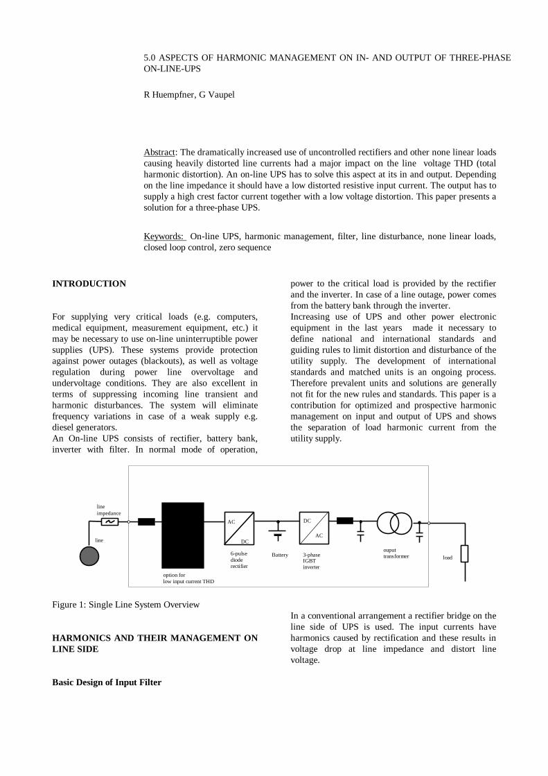
For supplying very critical loads (e.g. computers,medical equipment, measurement equipment, etc.) itmay be necessary to use on-line uninterruptible powersupplies (UPS). These systems provide protectionagainst power outages (blackouts), as well as voltageregulation during power line overvoltage andundervoltage conditions. They are also excellent interms of suppressing incoming line transient andharmonic disturbances. The system will eliminatefrequency variations in case of a weak supply e.g.diesel generators.An On-line UPS consists of rectifier, battery bank,inverter with filter. In normal mode of operation,
power to the critical load is provided by the rectifierand the inverter. In case of a line outage, power comesfrom the battery bank through the inverter.Increasing use of UPS and other power electronicequipment in the last years made it necessary todefine national and international standards andguiding rules to limit distortion and disturbance of theutility supply. The development of internationalstandards and matched units is an ongoing process.Therefore prevalent units and solutions are generallynot fit for the new rules and standards. This paper is acontribution for optimized and prospective harmonicmanagement on input and output of UPS and showsthe separation of load harmonic current from theutility supply.
line
lineimpedance
6-pulsedioderectifier
AC
DCAC
DC
3-phaseIGBTinverter
ouputtransformer load
option forlow input current THD
Battery
Figure 1: Single Line System Overview
HARMONICS AND THEIR MANAGEMENT ONLINE SIDE
Basic Design of Input Filter
In a conventional arrangement a rectifier bridge on theline side of UPS is used. The input currents haveharmonics caused by rectification and these results involtage drop at line impedance and distort linevoltage.
rms
ii
totalTHD
rms
rms= =
∞
∑ 2
22
THDrms Total harmonic distortion related total rmsrms root means sqare (rms) value of waveformrmsi harmonic rms of order i
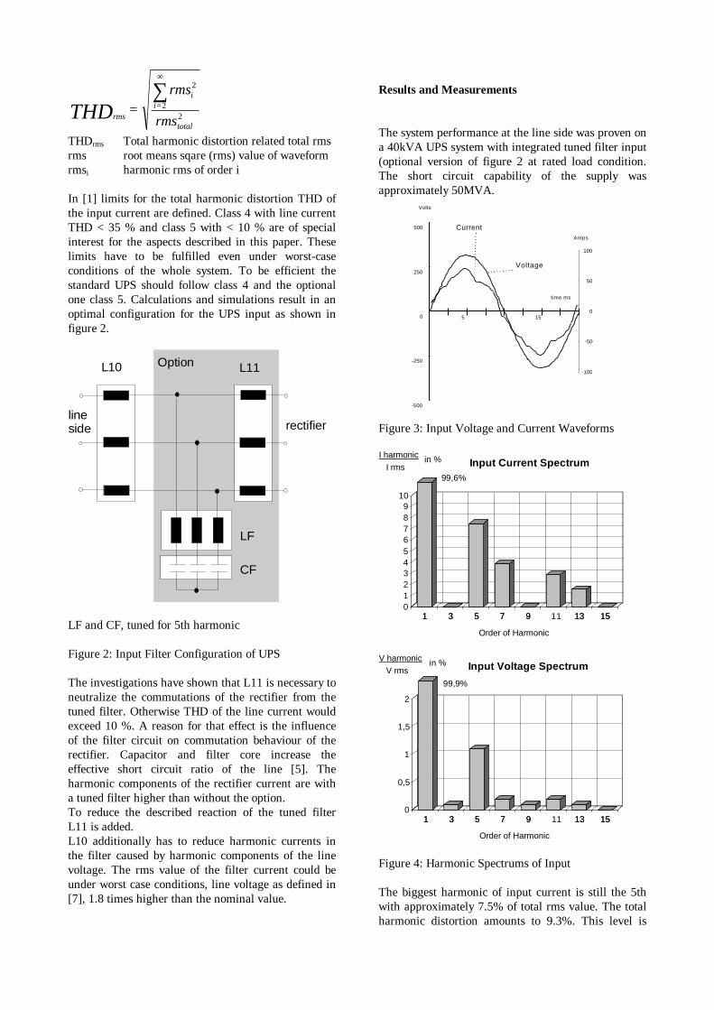
In [1] limits for the total harmonic distortion THD ofthe input current are defined. Class 4 with line currentTHD < 35 % and class 5 with < 10 % are of specialinterest for the aspects described in this paper. Theselimits have to be fulfilled even under worst-caseconditions of the whole system. To be efficient thestandard UPS should follow class 4 and the optionalone class 5. Calculations and simulations result in anoptimal configuration for the UPS input as shown infigure 2.
L10 L11
LF
CF
lineside rectifier
Option
LF and CF, tuned for 5th harmonic
Figure 2: Input Filter Configuration of UPS
The investigations have shown that L11 is necessary toneutralize the commutations of the rectifier from thetuned filter. Otherwise THD of the line current wouldexceed 10 %. A reason for that effect is the influenceof the filter circuit on commutation behaviour of therectifier. Capacitor and filter core increase theeffective short circuit ratio of the line [5]. Theharmonic components of the rectifier current are witha tuned filter higher than without the option.To reduce the described reaction of the tuned filterL11 is added.L10 additionally has to reduce harmonic currents inthe filter caused by harmonic components of the linevoltage. The rms value of the filter current could beunder worst case conditions, line voltage as defined in[7], 1.8 times higher than the nominal value.
Results and Measurements
The system performance at the line side was proven ona 40kVA UPS system with integrated tuned filter input(optional version of figure 2 at rated load condition.The short circuit capability of the supply wasapproximately 50MVA.
time ms
Volts
0
250
500
-250
-500
5 15
CurrentAmps
0
50
100
-50
-100
Voltage
Figure 3: Input Voltage and Current Waveforms
1 3 5 7 9 11 13 150123456789
10
1 3 5 7 9 13 15
Order of Harmonic
Input Current SpectrumI harmonic
I rmsin %
99,6%
1 3 5 7 9 13 150
0,5
1
1,5
2
1 3 5 7 9 11 13 15
Order of Harmonic
Input Voltage SpectrumV harmonic
V rmsin %
99,9%
Figure 4: Harmonic Spectrums of Input
The biggest harmonic of input current is still the 5thwith approximately 7.5% of total rms value. The totalharmonic distortion amounts to 9.3%. This level is
mainly influenced by the value of the 5th. The stiffline represents then worst case condition concerningfilter performance. If the line impedance goes up, theinput current THD will remarkably be reduced.The line voltage in figure 3 has a 5th harmonic of1.1% which is inherent in supply due to other loadsconnected to the same line. This value is alsomeasured without loaded. UPS The input reactor L10limits the 5th harmonic current driven by the linevoltage source into the tuned filter. It prevents thefilter from overload up to a 5th harmonic line voltagelevel of 5%. This limit is defined in [7].
HARMONIC MANAGEMENT ON THE LOADSIDE
Design and Analysis
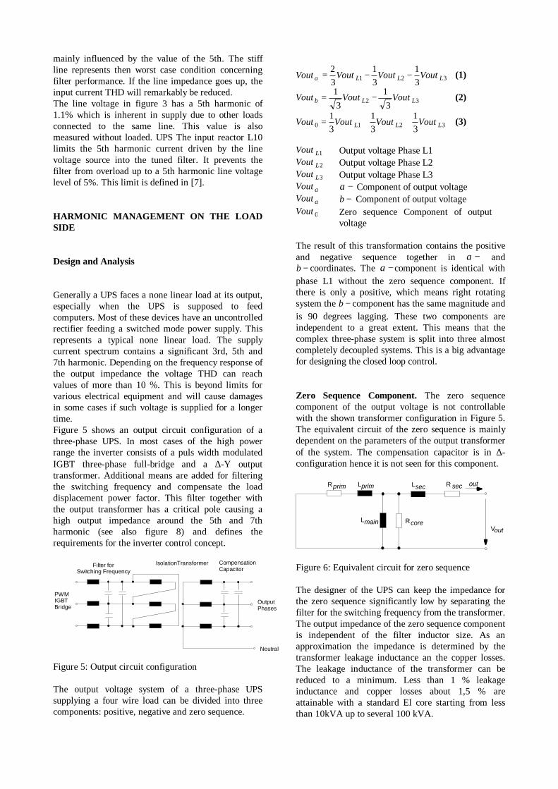
Generally a UPS faces a none linear load at its output,especially when the UPS is supposed to feedcomputers. Most of these devices have an uncontrolledrectifier feeding a switched mode power supply. Thisrepresents a typical none linear load. The supplycurrent spectrum contains a significant 3rd, 5th and7th harmonic. Depending on the frequency response ofthe output impedance the voltage THD can reachvalues of more than 10 %. This is beyond limits forvarious electrical equipment and will cause damagesin some cases if such voltage is supplied for a longertime.Figure 5 shows an output circuit configuration of athree-phase UPS. In most cases of the high powerrange the inverter consists of a puls width modulatedIGBT three-phase full-bridge and a ∆-Y outputtransformer. Additional means are added for filteringthe switching frequency and compensate the loaddisplacement power factor. This filter together withthe output transformer has a critical pole causing ahigh output impedance around the 5th and 7thharmonic (see also figure 8) and defines therequirements for the inverter control concept.
Neutral
OutputPhases
IsolationTransformerFilter forSwitching Frequency
CompensationCapacitor
PWMIGBTBridge
Figure 5: Output circuit configuration
The output voltage system of a three-phase UPSsupplying a four wire load can be divided into threecomponents: positive, negative and zero sequence.
Vout Vout Vout VoutL L Lα = − −23
13
131 2 3 (1)
Vout Vout VoutL Lβ = −13
132 3 (2)
Vout Vout Vout VoutL L L0 1 2 313
13
13
= + + (3)
Vout L1 Output voltage Phase L1Vout L2 Output voltage Phase L2Vout L3 Output voltage Phase L3Vout α α − Component of output voltageVout α β − Component of output voltageVout 0 Zero sequence Component of output
voltage
The result of this transformation contains the positiveand negative sequence together in α − andβ − coordinates. The α − component is identical withphase L1 without the zero sequence component. Ifthere is only a positive, which means right rotatingsystem the β − component has the same magnitude andis 90 degrees lagging. These two components areindependent to a great extent. This means that thecomplex three-phase system is split into three almostcompletely decoupled systems. This is a big advantagefor designing the closed loop control.
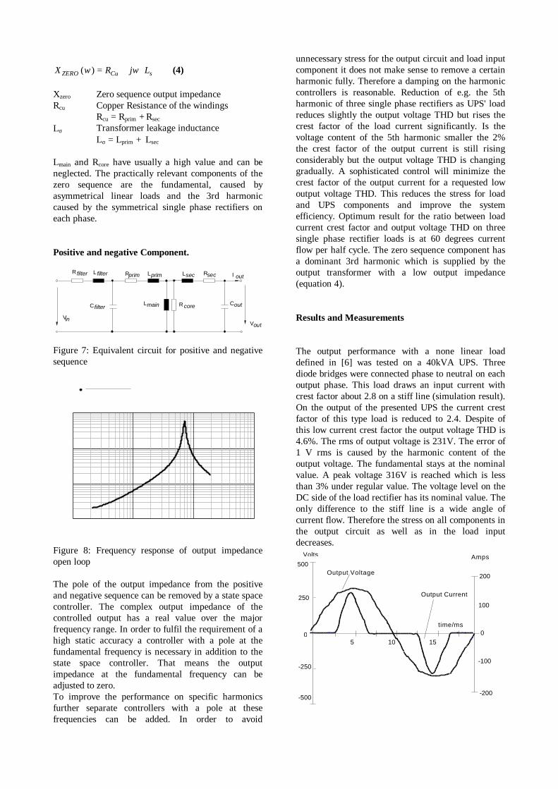
Zero Sequence Component. The zero sequencecomponent of the output voltage is not controllablewith the shown transformer configuration in Figure 5.The equivalent circuit of the zero sequence is mainlydependent on the parameters of the output transformerof the system. The compensation capacitor is in ∆-configuration hence it is not seen for this component.
R secLsec
Rcore
Rprim Lprim
Lmain
out
Vout
Figure 6: Equivalent circuit for zero sequence
The designer of the UPS can keep the impedance forthe zero sequence significantly low by separating thefilter for the switching frequency from the transformer.The output impedance of the zero sequence componentis independent of the filter inductor size. As anapproximation the impedance is determined by thetransformer leakage inductance an the copper losses.The leakage inductance of the transformer can bereduced to a minimum. Less than 1 % leakageinductance and copper losses about 1,5 % areattainable with a standard El core starting from lessthan 10kVA up to several 100 kVA.
X R j LZERO Cu( )ω ω σ= + ⋅ (4)
Xzero Zero sequence output impedanceRcu Copper Resistance of the windings
Rcu = Rprim + Rsec
Lσ Transformer leakage inductanceLσ = Lprim + Lsec
Lmain and Rcore have usually a high value and can beneglected. The practically relevant components of thezero sequence are the fundamental, caused byasymmetrical linear loads and the 3rd harmoniccaused by the symmetrical single phase rectifiers oneach phase.
Positive and negative Component.
R filter L filter
Cfilter
Vin
Rprim
Lmain
Lprim RsecLsec
R core Cout
I out
Vout
Figure 7: Equivalent circuit for positive and negativesequence
Figure 8: Frequency response of output impedanceopen loop
The pole of the output impedance from the positiveand negative sequence can be removed by a state spacecontroller. The complex output impedance of thecontrolled output has a real value over the majorfrequency range. In order to fulfil the requirement of ahigh static accuracy a controller with a pole at thefundamental frequency is necessary in addition to thestate space controller. That means the outputimpedance at the fundamental frequency can beadjusted to zero.To improve the performance on specific harmonicsfurther separate controllers with a pole at thesefrequencies can be added. In order to avoid
unnecessary stress for the output circuit and load inputcomponent it does not make sense to remove a certainharmonic fully. Therefore a damping on the harmoniccontrollers is reasonable. Reduction of e.g. the 5thharmonic of three single phase rectifiers as UPS' loadreduces slightly the output voltage THD but rises thecrest factor of the load current significantly. Is thevoltage content of the 5th harmonic smaller the 2%the crest factor of the output current is still risingconsiderably but the output voltage THD is changinggradually. A sophisticated control will minimize thecrest factor of the output current for a requested lowoutput voltage THD. This reduces the stress for loadand UPS components and improve the systemefficiency. Optimum result for the ratio between loadcurrent crest factor and output voltage THD on threesingle phase rectifier loads is at 60 degrees currentflow per half cycle. The zero sequence component hasa dominant 3rd harmonic which is supplied by theoutput transformer with a low output impedance(equation 4).
Results and Measurements
The output performance with a none linear loaddefined in [6] was tested on a 40kVA UPS. Threediode bridges were connected phase to neutral on eachoutput phase. This load draws an input current withcrest factor about 2.8 on a stiff line (simulation result).On the output of the presented UPS the current crestfactor of this type load is reduced to 2.4. Despite ofthis low current crest factor the output voltage THD is4.6%. The rms of output voltage is 231V. The error of1 V rms is caused by the harmonic content of theoutput voltage. The fundamental stays at the nominalvalue. A peak voltage 316V is reached which is lessthan 3% under regular value. The voltage level on theDC side of the load rectifier has its nominal value. Theonly difference to the stiff line is a wide angle ofcurrent flow. Therefore the stress on all components inthe output circuit as well as in the load inputdecreases.
Output Voltage
time/ms
Volts
0
250
500
-250
-500
5 10 15
Amps
Output Current
0
100
200
-100
-200
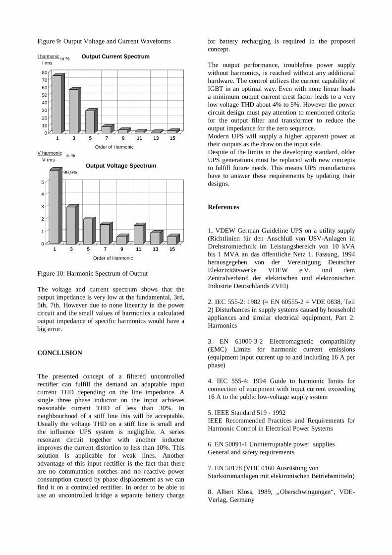
Figure 9: Output Voltage and Current Waveforms
1 3 5 7 9 11 13 150
10
20
30
40
50
60
70
80
1 3 5 7 9 11 13 15
Order of Harmonic
Output Current SpectrumI harmonicI rms
in %
1 3 5 7 9 11 13 150
1
2
3
4
5
1 3 5 7 9 11 13 15
Order of Harmonic
Output Voltage Spectrum
V harmonicV rms
in %
99,9%
Figure 10: Harmonic Spectrum of Output
The voltage and current spectrum shows that theoutput impedance is very low at the fundamental, 3rd,5th, 7th. However due to none linearity in the powercircuit and the small values of harmonics a calculatedoutput impedance of specific harmonics would have abig error.
CONCLUSION
The presented concept of a filtered uncontrolledrectifier can fulfill the demand an adaptable inputcurrent THD depending on the line impedance. Asingle three phase inductor on the input achievesreasonable current THD of less than 30%. Inneighbourhood of a stiff line this will be acceptable.Usually the voltage THD on a stiff line is small andthe influence UPS system is negligible. A seriesresonant circuit together with another inductorimproves the current distortion to less than 10%. Thissolution is applicable for weak lines. Anotheradvantage of this input rectifier is the fact that thereare no commutation notches and no reactive powerconsumption caused by phase displacement as we canfind it on a controlled rectifier. In order to be able touse an uncontrolled bridge a separate battery charge
for battery recharging is required in the proposedconcept.
The output performance, troublefree power supplywithout harmonics, is reached without any additionalhardware. The control utilizes the current capability ofIGBT in an optimal way. Even with none linear loadsa minimum output current crest factor leads to a verylow voltage THD about 4% to 5%. However the powercircuit design must pay attention to mentioned criteriafor the output filter and transformer to reduce theoutput impedance for the zero sequence.Modern UPS will supply a higher apparent power attheir outputs as the draw on the input side.Despite of the limits in the developing standard, olderUPS generations must be replaced with new conceptsto fulfill future needs. This means UPS manufactureshave to answer these requirements by updating theirdesigns.
References
1. VDEW German Guideline UPS on a utility supply(Richtlinien für den Anschluß von USV-Anlagen inDrehstromtechnik im Leistungsbereich von 10 kVAbis 1 MVA an das öffentliche Netz 1. Fassung, 1994herausgegeben von der Vereinigung DeutscherElektrizitätswerke VDEW e.V. und demZentralverband der elektrischen und elektronischenIndustrie Deutschlands ZVEI)
2. IEC 555-2: 1982 (= EN 60555-2 = VDE 0838, Teil2) Disturbances in supply systems caused by householdappliances and similar electrical equipment, Part 2:Harmonics
3. EN 61000-3-2 Electromagnetic compatibility(EMC) Limits for harmonic current emissions(equipment input current up to and including 16 A perphase)
4. IEC 555-4: 1994 Guide to harmonic limits forconnection of equipment with input current exceeding16 A to the public low-voltage supply system
5. IEEE Standard 519 - 1992IEEE Recommended Practices and Requirements forHarmonic Control in Electrical Power Systems
6. EN 50091-1 Uninterruptable power suppliesGeneral and safety requirements
7. EN 50178 (VDE 0160 Ausrüstung vonStarkstromanlagen mit elektronischen Betriebsmitteln)
8. Albert Kloss, 1989, „Oberschwingungen“, VDE-Verlag, Germany

89 Mohan, Undeland, Robbins, 1989 „PowerElectronics“, John Wiley & Sons
10. Redl, Richard, New Techniques for Line-Harmonics Reduction, PCIM 1997, Nürnberg

www.chloridepower.com
This publication is issued to provide outline information only and is not deemed to form any
part of any offer and contract.The company has apolicy of continuous product development and
improvement, and we therefore reserve the rightto vary any information without prior notice.
Cert No FM 10144
MI/Solutions/ed.3/Dec 02/E
Chloride UPS SystemsWORLD HEADQUARTERSVia Fornace 3040023 Castel Guelfo (BO)ItalyTelephone: +39 0542 632 111Facsimile: +39 0542 632 [email protected]
Closest Chloride Contact: