Embed Size (px)
Citation preview

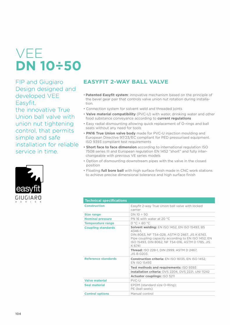
VEE DN 10÷50PVC-U
Easyfit 2-way ball valve
104
Technical specificationsConstruction Easyfit 2-way True Union ball valve with locked
carrierSize range DN 10 ÷ 50 Nominal pressure PN 16 with water at 20 °CTemperature range 0 °C ÷ 60 °CCoupling standards Solvent welding: EN ISO 1452, EN ISO 15493, BS
4346-1, DIN 8063, NF T54-028, ASTM D 2467, JIS K 6743. Pipe coupling capacity according to EN ISO 1452, EN ISO 15493, DIN 8062, NF T54-016, ASTM D 1785, JIS K 6741Thread: ISO 228-1, DIN 2999, ASTM D 2467, JIS B 0203.
Reference standards Construction criteria: EN ISO 16135, EN ISO 1452, EN ISO 15493Test methods and requirements: ISO 9393 Installation criteria: DVS 2204, DVS 2221, UNI 11242Actuator couplings: ISO 5211
Valve material PVC-USeal material EPDM (standard size O-Ring);
PE (ball seats) Control options Manual control
VEE
FIP and Giugiaro Design designed anddeveloped VEE Easyfit,the innovative True Union ball valve with union nut tightening control, that permits simple and safe installation for reliable service in time.
EASYFIT 2-WAY BALL VALVE
• Patented Easyfit system: innovative mechanism based on the principle of the bevel gear pair that controls valve union nut rotation during installa-tion.
• Connection system for solvent weld and threaded joints• Valve material compatibility (PVC-U) with water, drinking water and other
food substance conveyance according to current regulations• Easy radial dismounting allowing quick replacement of O-rings and ball
seats without any need for tools • PN16 True Union valve body made for PVC-U injection moulding and
European Directive 97/23/EC compliant for PED pressurised equipment. ISO 9393 compliant test requirements
• Short face to face dimension according to international regulation ISO 7508 series III and European regulation EN 1452 ”short” and fully inter-changeable with previous VE series models
• Option of dismounting downstream pipes with the valve in the closed position
• Floating full bore ball with high surface finish made in CNC work stations to achieve precise dimensional tolerance and high surface finish
DN 10÷50
21
3
105
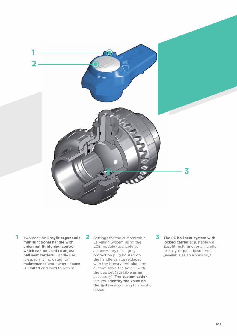
1 Two position Easyfit ergonomic multifunctional handle with union nut tightening control which can be used to adjust ball seat carriers. Handle use is especially indicated for maintenance work where space is limited and hard to access
2 Settings for the customisable Labelling System using the LCE module (available as an accessory). The grey protection plug housed on the handle can be replaced with the transparent plug and customisable tag holder with the LSE set (available as an accessory). The customisation lets you identify the valve on the system according to specific needs
3 The PE ball seat system with locked carrier adjustable via Easyfit multifunctional handle or Easytorque adjustment kit (available as an accessory)

106
TECHNICAL DATA-40 -20 0 20 40 60 80 100 120 140 °C
16
14
12
10
8
6
4
2
0
Wo
rkin
g p
ress
ure
Working temperature
barPRESSURE VARIATION ACCORDING TO TEMPERATURE
For water and harmless fluids to which the material is classified as CHEMICALLY RESISTANT. In other cases, a reduction of the nominal PN pressure is required (25 years with safety factor).
The information in this leaflet is provided in good faith. No liability will be accepted concerning technical data that is not directly covered by recognised international standards. FIP reserves the right to carry out any modification. Products must be installed and maintained by qualified personnel.
PRESSURE DROP GRAPH
Pre
ssur
e d
rop
Flow Rate
bar1 10 100 1000 10000 l/min
1
0.1
0.01
0.001
DN
15
DN
10
DN
20
DN
25
DN
32
DN
40
DN
50
KV100 FLOW COEFFICIENTThe Kv100 flow coefficient is the Q flow rate of litres per minute of water at a temperature of 20°C that will generate 'p= 1 bar pressure drop at a certain valve position.The Kv100 values shown in the table are calculated with the valve completely open.
DN 10 15 20 25 32 40 50
Kv100 l/min 80 200 385 770 1100 1750 3400
107
R DN PN B C C1 E H L Z g Code
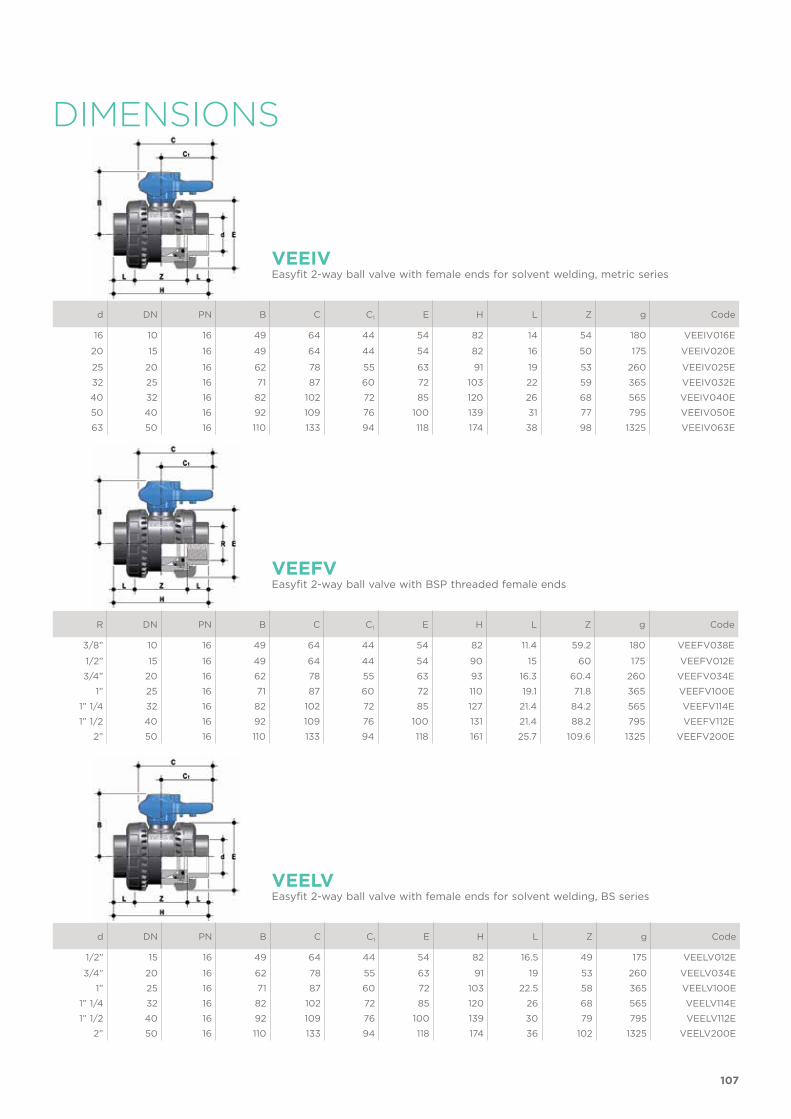
3/8” 10 16 49 64 44 54 82 11.4 59.2 180 VEEFV038E
1/2” 15 16 49 64 44 54 90 15 60 175 VEEFV012E3/4” 20 16 62 78 55 63 93 16.3 60.4 260 VEEFV034E
1” 25 16 71 87 60 72 110 19.1 71.8 365 VEEFV100E1” 1/4 32 16 82 102 72 85 127 21.4 84.2 565 VEEFV114E1” 1/2 40 16 92 109 76 100 131 21.4 88.2 795 VEEFV112E
2” 50 16 110 133 94 118 161 25.7 109.6 1325 VEEFV200E
DIMENSIONS
d DN PN B C C1 E H L Z g Code
16 10 16 49 64 44 54 82 14 54 180 VEEIV016E
20 15 16 49 64 44 54 82 16 50 175 VEEIV020E
25 20 16 62 78 55 63 91 19 53 260 VEEIV025E32 25 16 71 87 60 72 103 22 59 365 VEEIV032E40 32 16 82 102 72 85 120 26 68 565 VEEIV040E50 40 16 92 109 76 100 139 31 77 795 VEEIV050E63 50 16 110 133 94 118 174 38 98 1325 VEEIV063E
VEEIVEasyfit 2-way ball valve with female ends for solvent welding, metric series
VEEFVEasyfit 2-way ball valve with BSP threaded female ends
d DN PN B C C1 E H L Z g Code
1/2” 15 16 49 64 44 54 82 16.5 49 175 VEELV012E
3/4” 20 16 62 78 55 63 91 19 53 260 VEELV034E1” 25 16 71 87 60 72 103 22.5 58 365 VEELV100E
1” 1/4 32 16 82 102 72 85 120 26 68 565 VEELV114E1” 1/2 40 16 92 109 76 100 139 30 79 795 VEELV112E
2” 50 16 110 133 94 118 174 36 102 1325 VEELV200E
VEELVEasyfit 2-way ball valve with female ends for solvent welding, BS series

d DN PN B C C1 E H L Z g Code
1/2” 15 16 49 64 44 54 96 22.5 51 175 VEEAV012E
3/4” 20 16 62 78 55 63 105 25.5 54 260 VEEAV034E1” 25 16 71 87 60 72 117 28.7 59.5 365 VEEAV100E
1” 1/4 32 16 82 102 72 85 136 32 72 565 VEEAV114E1” 1/2 40 16 92 109 76 100 147 35 77 795 VEEAV112E
2” 50 16 110 133 94 118 174 38.2 97.6 1325 VEEAV200E
VEEAVEasyfit 2-way ball valve with female ends for solvent welding, ASTM series
R DN PN B C C1 E H L Z g Code
3/8” 10 16 49 64 44 54 82 13.7 54.6 180 VEENV038E
1/2” 15 16 49 64 44 54 90 17.8 54.4 175 VEENV012E3/4” 20 16 62 78 55 63 93 18 57 260 VEENV034E
1” 25 16 71 87 60 72 110 22.6 64.8 365 VEENV100E1” 1/4 32 16 82 102 72 85 127 25.1 76.8 565 VEENV114E1” 1/2 40 16 92 109 76 100 131 24.7 81.6 795 VEENV112E
2” 50 16 110 133 94 118 161 29.6 101.8 1325 VEENV200E
VEENVEasyfit 2-way ball valve with female ends, NPT thread
d DN PN B C C1 E H L Z g Code
1/2” 15 16 49 64 44 54 110 30 50 195 VEEJV012E
3/4” 20 16 62 78 55 63 123 35 53 285 VEEJV034E1” 25 16 71 87 60 72 139 40 59 395 VEEJV100E
1” 1/4 32 16 82 102 72 85 156 44 68 600 VEEJV114E1” 1/2 40 16 92 109 76 100 187 55 77 835 VEEJV112E
2” 50 16 110 133 94 118 228 63 102 1375 VEEJV200E
VEEJVEasyfit 2-way ball valve with female ends for solvent welding, JIS series
108
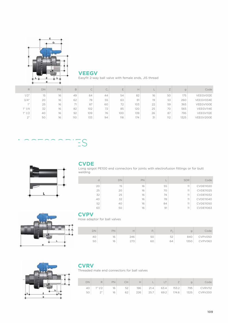
R DN PN B C C1 E H L Z g Code
1/2” 15 16 49 64 44 54 82 16 50 175 VEEGV012E
3/4” 20 16 62 78 55 63 91 19 53 260 VEEGV034E1” 25 16 71 87 60 72 103 22 59 365 VEEGV100E
1” 1/4 32 16 82 102 72 85 120 25 70 565 VEEGV114E1” 1/2 40 16 92 109 76 100 139 26 87 795 VEEGV112E
2” 50 16 110 133 94 118 174 31 112 1325 VEEGV200E
VEEGVEasyfit 2-way ball valve with female ends, JIS thread
ACCESSORIES
DN R PN CH H L LT Z g Code
40 1” 1/2 16 52 196 21.4 63.4 153.2 795 CVRV11250 2” 16 62 226 25.7 69.2 174.6 1325 CVRV200
CVRVThreaded male end connectors for ball valves
DN PN H P1 P2 g Code
40 16 246 50 52 840 CVPV05050 16 273 60 64 1350 CVPV063
CVPVHose adaptor for ball valves
d DN PN L SDR Code
20 15 16 55 11 CVDE1102025 20 16 70 11 CVDE1102532 25 16 74 11 CVDE1103240 32 16 78 11 CVDE1104052 40 16 84 11 CVDE1105063 50 16 91 11 CVDE11063
CVDELong spigot PE100 end connectors for joints with electrofusion fittings or for butt welding
109
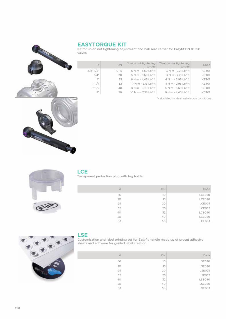
LSE
LCE
Customisation and label printing set for Easyfit handle made up of precut adhesive sheets and software for guided label creation.
Transparent protection plug with tag holder
d DN Code
16 10 LSE020
20 15 LSE02025 20 LSE025
32 25 LSE03240 32 LSE04050 40 LSE05063 50 LSE063
d DN Code
16 10 LCE020
20 15 LCE02025 20 LCE025
32 25 LCE03240 32 LCE04050 40 LCE05063 50 LCE063
EASYTORQUE KITKit for union nut tightening adjustment and ball seat carrier for Easyfit DN 10÷50 valves.
d DN *Union nut tightening torque
*Seat carrier tightening torque Code
3/8”-1/2” 10-15 5 N m - 3,69 Lbf ft 3 N m - 2,21 Lbf ft KET013/4” 20 5 N m - 3,69 Lbf ft 3 N m - 2,21 Lbf ft KET01
1” 25 6 N m - 4,43 Lbf ft 4 N m - 2,95 Lbf ft KET011” 1/4 32 7 N m - 5,16 Lbf ft 4 N m - 2,95 Lbf ft KET011” 1/2 40 8 N m - 5,90 Lbf ft 5 N m - 3,69 Lbf ft KET01
2” 50 10 N m - 7,38 Lbf ft 6 N m - 4,43 Lbf ft KET01
*calculated in ideal installation conditions
110
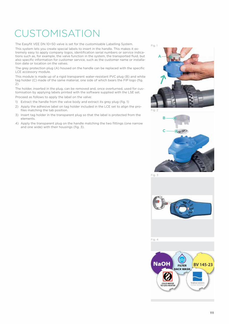
CUSTOMISATIONThe Easyfit VEE DN 10÷50 valve is set for the customisable Labelling System. This system lets you create special labels to insert in the handle. This makes it ex-tremely easy to apply company logos, identification serial numbers or service indica-tions such as, for example, the valve function in the system, the transported fluid, but also specific information for customer service, such as the customer name or installa-tion date or location on the valves.The grey protection plug (A) housed on the handle can be replaced with the specific LCE accessory module. This module is made up of a rigid transparent water-resistant PVC plug (B) and white tag holder (C) made of the same material, one side of which bears the FIP logo (fig. 2). The holder, inserted in the plug, can be removed and, once overturned, used for cus-tomisation by applying labels printed with the software supplied with the LSE set. Proceed as follows to apply the label on the valve:1) Extract the handle from the valve body and extract its grey plug (fig. 1)2) Apply the adhesive label on tag holder included in the LCE set to align the pro-
files matching the tab position.3) Insert tag holder in the transparent plug so that the label is protected from the
elements.4) Apply the transparent plug on the handle matching the two fittings (one narrow
and one wide) with their housings (fig. 3).
Fig. 1
Fig. 2
Fig. 4
Fig. 3
A
B
C
111

COMPONENTSEXPLODED VIEW
1 x Handle plug (PVC-U - 1)2 x Stem O-Ring
(EPDM - 2)*3 x Stem (PVC-U - 1)4 x Body (PVC-U - 1) 5 x Ball (PVC-U - 1)
* Spare parts
The component material and quantity supplied are indicated in the parentheses.
6 x Radial seal O-Ring (EPDM - 1)*7 x End connector (PVC-U - 2)8 x Ball seat carrier
(PVC-U - 1)9 x Ball seat (PE - 2)
10 x Socket seal O-Ring (EPDM - 2)*12 x Handle (HIPVC - 1)13 x Union nut (PVC-U - 2)
112
INSTALLATIONBefore proceeding with installation. please follow these instructions carefully:1) Check that the pipes to be connected to the valve are aligned in order to avoid
mechanical stress on the threaded joints.2) Unscrew the union nuts (13) and slide them onto the pipe.3) Solvent weld or screw the end connectors (7) onto the pipe segments.4) Position the valve between the end connectors (fig. 6). Warning: if a high pressure test is required, always position the body with the
"REGULAR" label upstream from the fluid direction.5) Fit the union nuts on the valve body and manually tighten clockwise until they be-
come hard to turn; do not use wrenches or other tools that can damage the union nut surfaces.
6) Extract the handle (12) from the valve body and extract its grey plug (1) (fig. 2)7) Overturn the handle and insert in on the valve stem matching the handle teeth (A)
with the union nut teeth (B) (fig. 9-10).8) Turn the handle counter-clockwise to fully tighten the union nut. The rotation
directions to tighten (TIGHTEN) and loosen (UNTIGHTEN) the union nuts are indi-cated on the handle (fig. 11). Generally, if pipes are not offset, one turn is sufficient for correct tightening.
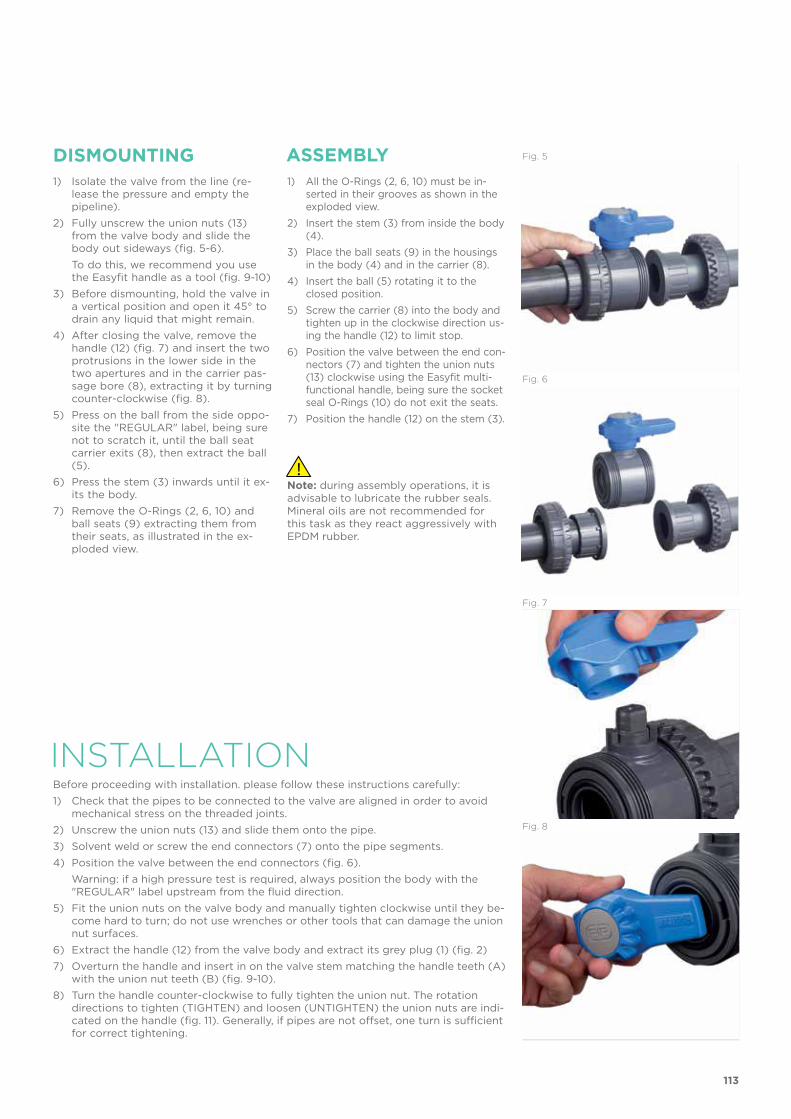
DISMOUNTING ASSEMBLY1) Isolate the valve from the line (re-
lease the pressure and empty the pipeline).
2) Fully unscrew the union nuts (13) from the valve body and slide the body out sideways (fig. 5-6).
To do this, we recommend you use the Easyfit handle as a tool (fig. 9-10)
3) Before dismounting, hold the valve in a vertical position and open it 45° to drain any liquid that might remain.
4) After closing the valve, remove the handle (12) (fig. 7) and insert the two protrusions in the lower side in the two apertures and in the carrier pas-sage bore (8), extracting it by turning counter-clockwise (fig. 8).
5) Press on the ball from the side oppo-site the "REGULAR" label, being sure not to scratch it, until the ball seat carrier exits (8), then extract the ball (5).
6) Press the stem (3) inwards until it ex-its the body.
7) Remove the O-Rings (2, 6, 10) and ball seats (9) extracting them from their seats, as illustrated in the ex-ploded view.
1) All the O-Rings (2, 6, 10) must be in-serted in their grooves as shown in the exploded view.
2) Insert the stem (3) from inside the body (4).
3) Place the ball seats (9) in the housings in the body (4) and in the carrier (8).
4) Insert the ball (5) rotating it to the closed position.
5) Screw the carrier (8) into the body and tighten up in the clockwise direction us-ing the handle (12) to limit stop.
6) Position the valve between the end con-nectors (7) and tighten the union nuts (13) clockwise using the Easyfit multi-functional handle, being sure the socket seal O-Rings (10) do not exit the seats.
7) Position the handle (12) on the stem (3).
Fig. 8
Fig. 7
Note: during assembly operations, it is advisable to lubricate the rubber seals. Mineral oils are not recommended for this task as they react aggressively with EPDM rubber.
Fig. 5
Fig. 6
113

WARNINGS
9) Repeat point 7 for the other union nut. Note: A small force applied on the handle develops a torque much higher than
manual tightening. You can also, using the Easytorque kit (fig. 12), supplied as an accessory, tighten
union nuts using a torque wrench to quantify the force and thus monitor the stress applied to the thermoplastic threads according to the installation indica-tions in the instructions enclosed with the kit.
10) Apply the plug (1) on the handle (12) matching the two fittings (one narrow and one wide) with the relevant housings on the handle (fig. 3).
11) Install the handle (12) on the stem (3) again.12) If necessary, support the pipe with FIP pipe clip model ZIKM and DSM distance
plates.
- If volatile liquid such as Hydrogen Peroxide (H2O2) or Sodium Hypochlorite (NaCIO) is used, for safety reasons we recommend you contact the service centre. These liquids, upon vaporising, could create hazardous over pressures in the area between the body and ball.
- Do not use compressed air or other gases to test thermoplastic lines.- Always avoid sudden closing manoeuvres and protect the valve from accidental
manoeuvres.
Fig. 9
Fig. 10
Fig. 11
Fig. 12
A
B
114
MANUAL VALVESPVC-U
The PVC-U manual valves line consists of a comprehensive range of ball valves, butterfly valves, diaphragm valves, check valves, sediment strainers,
air release valves, foot valves and angle seat valves for use in the construction of process and service lines for conveying pressurised industrial fluids and for
maximum operating temperatures of no more than 60°C
Cod
e LE
VAM
AV
FIP - Formatura Iniezione Polimeri Loc. Pian di Parata, 16015 Casella Genova ItalyTel. +39 010 9621.1 Fax +39 010 [email protected]
MA
NU
AL
PV
C-U
VA
LVE
S