Embed Size (px)
Citation preview

LIMITADOR DE VELOCIDAD/
OVERSPEED GOVERNOR/
LIMITEUR DE VITESSE/
GESCHWINDIGKEITSBEGRENZER/
VEGA
INSTRUCCIONES DE USO Y MANUTENCIÓN/
INSTRUCTIONS FOR USE AND MAINTENANCE/
INSTRUCTIONS D’USAGE ET ENTRETIEN/
GEBRAUCHS- UND WARTUNGSANLEITUNG/


INSTRUCTIONS: VEGA Cod: DYN 35.1.12 Date: 30/01/2017 Revision: 12
1
INSTRUCTIONS FOR USE AND MAINTENANCE
_________________________________________________________
1 GENERAL INSTRUCTIONS ........................................................................................................................... 2
2 OVERSPEED GOVERNOR IDENTIFICATION .............................................................................................. 2
3 MAIN COMPONENTS .................................................................................................................................... 2
4 WORKING PRINCIPLES ................................................................................................................................ 3
4.1 OVERSPEED CONTACT ....................................................................................................................... 5
4.2 REMOTE TRIPPING MECHANISM (OPTIONAL) ................................................................................. 6
4.3 REMOTE RESET DEVICE (OPTIONAL) ............................................................................................... 6
4.4 UNCONTROLLED MOVEMENT UCM DEVICE .................................................................................... 6
4.4.2 WARNINGS AND SUGGESTIONS ................................................................................................... 6
4.4.3 THE PARKING SYSTEM AS REMOTE CONTROL .......................................................................... 7
4.4.4 ANTI-CREEP SYSTEM MAINTENANCE .......................................................................................... 7
4.5 VEGA LS OVERSPEED GOVERNOR ................................................................................................... 8
4.6 ONE-WAY VEGA OVERSPEED GOVERNOR ...................................................................................... 8
4.7 VEGA HS ................................................................................................................................................ 8
4.8 HARDENED GROOVE........................................................................................................................... 9
4.9 VEGA GOVERNOR’S COVER .............................................................................................................. 9
5 VEGA PLUS.................................................................................................................................................... 9
6 FIXING TO THE FLOOR ................................................................................................................................ 9
7 TECHNICAL FEATURES ............................................................................................................................. 10
9 INSTRUCTIONS OF USE AND MAINTENANCE ........................................................................................ 11
9.1 STORAGE AND SERVICE LIFE .......................................................................................................... 11
10 INSTALLATION DRAWINGS ....................................................................................................................... 11
_________________________________________________________
Note: This manual displays partial information on the instructions for use and maintenance of this product. Please refer to the customer area in Dynatech’s website in order to consult the full manual; http://customers.dynatech-elevation.com/
INSTRUCTIONS: VEGA Cod: DYN 35.1.12 Date: 30/01/2017 Revision: 12
2
1 GENERAL INSTRUCTIONS
The DYNATECH VEGA overspeed governor is designed to cut off the current of the security series line in the event of car overspeed, bringing the lift to a standstill when necessary.
The VEGA overspeed governor covers a wide range of speeds and can be used with instant and progressive safety gears.
It is strictly forbidden:
a) To modify or replace the overspeed governor adjustment spring.
b) Use an overspeed governor in a lift for which it is not intended, or whose features do not correspond to those marked on the lift (e.g. nominal speed or rope type).
c) To adjust any component of the overspeed governor, except for those parts specified in the manual.
DYNATECH DYNAMICS & TECHNOLOGY, SL will not be liable for any damage caused by failure to observe any of these general conditions.
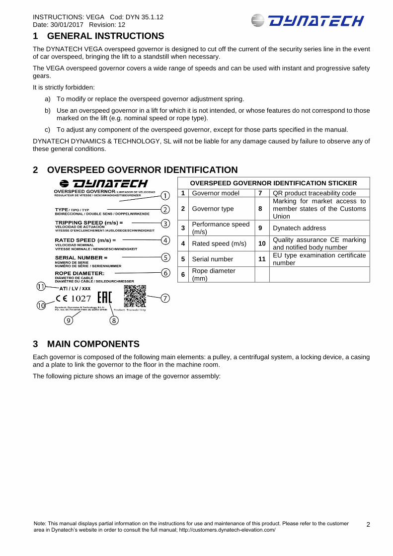
2 OVERSPEED GOVERNOR IDENTIFICATION
3 MAIN COMPONENTS
Each governor is composed of the following main elements: a pulley, a centrifugal system, a locking device, a casing and a plate to link the governor to the floor in the machine room.
The following picture shows an image of the governor assembly:
OVERSPEED GOVERNOR IDENTIFICATION STICKER
1 Governor model 7 QR product traceability code
2 Governor type 8 Marking for market access to member states of the Customs Union
3 Performance speed (m/s)
9 Dynatech address
4 Rated speed (m/s) 10 Quality assurance CE marking and notified body number
5 Serial number 11 EU type examination certificate number
6 Rope diameter (mm)
Note: This manual displays partial information on the instructions for use and maintenance of this product. Please refer to the customer area in Dynatech’s website in order to consult the full manual; http://customers.dynatech-elevation.com/

INSTRUCTIONS: VEGA Cod: DYN 35.1.12 Date: 30/01/2017 Revision: 12
3
Where:
(1) Main pulley. (2) Centrifugal system. (3) Locking system. (4) Floor fixing plate
4 WORKING PRINCIPLES
The governor is of the centrifugal type and is able to work either upwards or downwards.
The governor is fixed directly to the floor in the machine room or in the upper part of the well, joined by the rope to its tensing pulley located in the pit.
This tensing pulley is attached to the guide pulley by flanges.
The rope passes through the groove of the governor and the tensing pulley.
The ends of the rope are attached to the linkage anchoring. Thus, when the car reaches its tripping speed, the rope-governor relative movement will lock it.
The working diagram is as follows:
(1) VEGA governor
(2) Governor rope
(3) Tension weight
As it was indicated above, the governor is secured to the floor in the machine room or to the well.
The ends of the rope (2) are attached to the linkage anchoring (1) through eyes.
Note: This manual displays partial information on the instructions for use and maintenance of this product. Please refer to the customer area in Dynatech’s website in order to consult the full manual; http://customers.dynatech-elevation.com/

INSTRUCTIONS: VEGA Cod: DYN 35.1.12 Date: 30/01/2017 Revision: 12
4
The tension weight is secured to the guide rail by flanges.
The rope must have enough tension. In the event of tension loosening a rope slackening contact (1) connected to the installation security series will cut off the current.
Bidirectional version: 525 N on each branch
Unidirectional: 280 N on each branch
Note: This manual displays partial information on the instructions for use and maintenance of this product. Please refer to the customer area in Dynatech’s website in order to consult the full manual; http://customers.dynatech-elevation.com/

INSTRUCTIONS: VEGA Cod: DYN 35.1.12 Date: 30/01/2017 Revision: 12
5
4.1 OVERSPEED CONTACT
The governor has a built-in overspeed contact.
According to the European Standard UNE-EN 81:20, at the 5.6.2.2.1.6 section, the current cut off by means of the overspeed governor contact is mentioned. In this section is specified that for rated speeds of no more than 1 m/s, the overspeed contact can be triggered when the governor locks.
Therefore, the governors, whose rating speed is 1 m/s or lower, will be provided with an overspeed switch that is triggered at the same time as the governor locks.
In the left picture the contact situation is shown (1).
The contact will act when the governor reaches a speed above the rated speed and a moment before the governor actuates.
When this contact is triggered, the current of the security series is cut off.
This system has a remote reset.
For rated speeds above 1 m/s, the overspeed switch must be triggered at a speed above the rated speed, but bellow the tripping speed of the governor.
The contact (2) is shown in the right picture.
This system has a manually reset.
If the governor acts on this contact, the current of the security circuit will not circulate until this contact is manually returned to its initial position
Remark: For installations in the well or similar, an automatic reset for this contact is possible. See afterwards
Note: This manual displays partial information on the instructions for use and maintenance of this product. Please refer to the customer area in Dynatech’s website in order to consult the full manual; http://customers.dynatech-elevation.com/

INSTRUCTIONS: VEGA Cod: DYN 35.1.12 Date: 30/01/2017 Revision: 12
6
4.2 REMOTE TRIPPING MECHANISM (OPTIONAL)
The governor can have a built-in remote tripping mechanism to check the correct interlocking of the governor and the subsequent safety gear wedging.
Basically, it consists of a remote interlocking electromagnetic system, which can be driven from the engine room. In order to help during the installation, three versions of the system are available:
Solenoid fed by 24 V DC (direct current). A current of 1,2 A must be provided.
Solenoid fed by 48 V DC (direct current). A current of 0,54 A must be provided.
Solenoid fed by 190 V DC (direct current). A current of 0.16 A must be provided.
Remark: Anyway, just a few seconds are necessary to engage the governor. After the activation, the current that feeds the solenoid must be switched off to avoid its overheating. In that way, a button is recommended to activate the system.
4.3 REMOTE RESET DEVICE (OPTIONAL)
The governor has the option of a remote reset (R) of the overspeed contact (2). For this device, a solenoid of 24, 48 or 190 V with a current of 1.2, 0.54 and 0.16 A, respectively, is used.
4.4 UNCONTROLLED MOVEMENT UCM DEVICE
4.4.2 WARNINGS AND SUGGESTIONS
The anti-creep system requires the lift controller to be able to manage the functions that the anti-creep system uses, such as the coil power, control sensor monitoring and manual rescue. If the controller is unable to manage these functions, Dynatech offers the possibility of installing an electronic module, D-Box. For more information, see the website.
If the D-Box is not used, please observe the following warnings and follow the recommendations below for proper controller design.
Note. It is highly recommended that the controller designer contacts Dynatech before designing the circuit to manage the anti-creep system, to clarify any doubts regarding connections and to be recommended a specific solution for their installation:
- Locking the overspeed governor after UCM can be done by either of the following 2 methods: 1) Detecting the UCM or 2) Letting the anti-creep system act.
1) To detect the UCM, either a sensor needs to be placed on each floor or, as is the case with the D-Box, a levelling signal needs to be used. Therefore, if the car creeps with the doors open, the sensor detects it and cuts off the current to the anti-creep system coil, thus locking the overspeed governor.
2) In this case, the anti-creep system clamping device is locked at each floor in the installation. When the lift moves, the anti-creep system coil is excited and releases the overspeed governor. Then, once the car reaches one of the floors, the current to the coil is cut, leaving the anti-creep system in the locked position.
- The D-Box has a feature whereby, when the elevator reaches a floor, current continues through the coil for a set time, usually 10 minutes, if the lift does not receive another call. After this time, the anti-creep system locking device is activated. This correction is due to the VDI 4707 Part 1 (German lift energy efficiency standard) which establishes a period of 5 minutes before stand-by.
Thus, the anti-creep system performs fewer on-off cycles, thereby increasing its useful life.
This is helpful in periods when there is heavy traffic, as it prevents the anti-creep system from repeatedly locking and unlocking the overspeed governor.
It must be remembered that a UCM sensor will need to be installed if the anti-creep system works this way.
- It is recommended to over-excite the coil with a voltage slightly above nominal for less than one second to ensure the anti-creep system unlocks. Once it is unlocked and the lift begins to move, the supply voltage should be reduced during the journey to lessen the coil heating.
Also, if the choice of keeping the coil excited while the lift is at a floor is taken, the voltage to the solenoid can also be lowered. This saves energy and improves the energy efficiency of the lift.
Note: This manual displays partial information on the instructions for use and maintenance of this product. Please refer to the customer area in Dynatech’s website in order to consult the full manual; http://customers.dynatech-elevation.com/

INSTRUCTIONS: VEGA Cod: DYN 35.1.12 Date: 30/01/2017 Revision: 12
7
Below is a table of recommended voltages.
All values - V Over-excitation Voltage during
travel Voltage at floor
24 30 20 12
48 60 40 30
190 215-205* 150 104
* This is the voltage at the rectifier output, which can vary between the values shown.
- To ensure proper operation of the device, it is advisable to design a circuit such that, if the inductive sensor does not detect the anti-creep system unlocking, the controller will try more than once to supply current to the coil (the Dynatech D-Box makes 7 attempts before the error message appears that no reading for the inductive sensor is detected).
Thus, if there is any mechanical fault preventing the sensor from being read, the same attempts to solve the problem will be made before an error message appears on the controller.
- To prevent the car from stopping due to the loss of the inductive sensor signal while travelling, it makes a reading only at the floors.
- In the event of a cut in the electricity supply to the electric magnet coil when the car is moving, the speed governor will lock and the safety gear subsequently engaged.
The installation of an autonomous power system is recommended to avoid undesired engagement in the event of a cut in the mains electricity supply.
- Open the pin to enable the speed governor to turn for manual rescue. If the pin is not released, the governor will lock and the safety gear will engage during the rescue movement.
- Open the pin to enable the speed governor to turn for automatic rescue. If the pin is not released, the governor will lock and the safety gear will engage during the rescue movement.
- Use in installations with re-levelling over 20 mm: in installations with re-levelling over 20 mm, certified switching must be used to activate the electric magnet during the re-levelling process because if it re-levels by more than 20 mm then the governor could lock and the safety gear engage. In this case, the switching must discriminate between re-levelling and an uncontrolled movement.
- Use in installations with door pre-opening: in installations with door pre-opening, certified switching must be used to ensure the electric magnet remains activated during the pre-opening process because if the electric magnet does not remain activated then the governor could lock and the safety gear engage. In this case, the switching must discriminate between pre-opening and an uncontrolled movement.
4.4.3 THE PARKING SYSTEM AS REMOTE CONTROL
The parking system can be used as remote control.
Operations are the opposite to those of the parking system, as it unlocks the governor when the lift is running under normal conditions.
The purpose of the remote control system is to lock the governor when the lift is moving. This takes place during engagement tests. On locking the governor, the safety gear is forced to operate.
To do so, a button must be installed on the control panel that disconnects the current to the parking system coil.
As indicated above, the parking system unlocks the governor by powering the solenoid valve in this system. If the governor is to be locked while the car is operating normally, this solenoid valve must be disconnected so that the parking system locks the governor.
4.4.4 ANTI-CREEP SYSTEM MAINTENANCE
It is very important that the anti-creep system is in the best possible condition. As it is a mechanism that will perform many cycles over its lifetime, it is advisable to check its condition and operation during lift maintenance.
The anti-creep system should be kept as free of dust and dirt as possible, to ensure the moving parts are not obstructed. It should be checked and cleaned of dirt if necessary. After cleaning, a lubricant should be applied to increase the mechanism life.
A spray type lubricant, which prevents the adhesion of dust, can be used on the parts shown in the figure.
Note: This manual displays partial information on the instructions for use and maintenance of this product. Please refer to the customer area in Dynatech’s website in order to consult the full manual; http://customers.dynatech-elevation.com/

INSTRUCTIONS: VEGA Cod: DYN 35.1.12 Date: 30/01/2017 Revision: 12
8
Attaching a protective cover will help prevent dirt from entering, and keep the mechanism in a cleaner condition.
4.5 VEGA LS OVERSPEED GOVERNOR
There is a low speed VEGA governor called VEGA LS.
The minimum performance speed is 0.40 m/s
This governor is DOWNWARDS ACTING ONLY and the performance speed range is: 0.40 – 0.70 m/s
Important Note: Customers asking for a VEGA LS, may know that it´s unidirectional. In order to know the right way, it must pay attention to the arrow in the governor.
4.6 ONE-WAY VEGA OVERSPEED GOVERNOR
The VEGA overspeed governor may be sent for any speed as a one-way overspeed governor.
Attention must be paid to the direction of rotation of the overspeed governor when it is one-way.
4.7 VEGA HS
There is a model for higher performance speeds of up to 4 m/s.
The performance speed range is 2.87-4 m/s.
Rated speeds would be 2.4-3.4 m/s.
May be bidirectional or unidirectional.
Note: This manual displays partial information on the instructions for use and maintenance of this product. Please refer to the customer area in Dynatech’s website in order to consult the full manual; http://customers.dynatech-elevation.com/

INSTRUCTIONS: VEGA Cod: DYN 35.1.12 Date: 30/01/2017 Revision: 12
9
4.8 HARDENED GROOVE
It is possible to order the governor with a hardened groove. The following data is provided to assess whether or not ordering the governor with this option is required.
Non-hardened groove: 500000 cycles
Hardened groove: 1500000 cycles
Note: This data is the result of tests performed on Dynatech premises and are for illustrative purposes only. The wear depends on the type of installation, traffic, tension on the governor rope, speed, etc. The client must decide whether or not to select this option depending on the type of installation
4.9 VEGA GOVERNOR’S COVER
As an option, a cover may be installed for the governor in order to avoid bumps, entanglement or other damage
caused by the rotation of the governor’s mobile parts.
This is a cover reaching the main part of the governor. It is easy to assemble.
5 VEGA PLUS
The VEGA Plus governor is characterised by the fact that it is fitted with an Encoder at the rear for permanent control of the position of the car
The Encoder turns thanks to a wheel gear system, with a gear ratio of 3. The angular speed at which the encoder turns is 3 times greater than that of the main pulley.
The Encoder supplied in the VEGA plus is the OMRON E6B2CWZ6C500 0.5M 24V.
This is a 500-pulse incremental encoder powered by 24 V.
For further information on the encoder indicated, all the information taken from the OMRON catalogue regarding this product is attached below.
Note: Clients preferring to install their own encoders should contact Dynatech for measurements and makes of Encoder to ensure that their encoder can be installed in the governor.
6 FIXING TO THE FLOOR
The figure shows the governor anchoring points to the lift floor. Distances appear in millimetres.
Note: This manual displays partial information on the instructions for use and maintenance of this product. Please refer to the customer area in Dynatech’s website in order to consult the full manual; http://customers.dynatech-elevation.com/

INSTRUCTIONS: VEGA Cod: DYN 35.1.12 Date: 30/01/2017 Revision: 12
10
The above figure represents the bottom view of the governor base plate (2).
The governor is anchored to the floor using the threaded holes (1) in the plate.
The rope (3) and its position with respect to the base plate can also be seen in the drawing.
7 TECHNICAL FEATURES
- Machine: Overspeed governor
- Model: VEGA
- Manufacturing company:
DYNATECH, DYNAMICS & TECHNOLOGY, S.L.
- Range of use:
Maximum rated speed: 2.40 m/s
Maximum tripping speed: 2.87 m/s
Minimum rated speed: 0.1 m/s
Minimum tripping speed:
o From 0.4 to 0.7 m/s , the governor is UNIDIRECTIONAL
o From 0.7 to 2.87 m/s the governor is BIDIRECTIONAL
- Rope:
Diameter: 6 mm, 6.3 mm, 6.5 mm.
Composition: 6 x 19 + 1
- Rope pre-tightness:
500 N
This tightness is achieved by positioning the tension weight so that the bar is horizontal.
- Tightness produced on the rope during interlocking:
Greater than 300 N
- Pulley diameter: 200 mm
- Overspeed contact.
- Other features:
It is possible to install several devices:
Note: This manual displays partial information on the instructions for use and maintenance of this product. Please refer to the customer area in Dynatech’s website in order to consult the full manual; http://customers.dynatech-elevation.com/

INSTRUCTIONS: VEGA Cod: DYN 35.1.12 Date: 30/01/2017 Revision: 12
11
- Remote tripping system
- Remote reset
- Parking System
- It can be unidirectional or bidirectional
- An encoder can be assembled (VEGA PLUS)
Possibility of ordering the pulley groove hardened
- Safety gears with which it may be used:
All safety gears with a tripping speed that can be reached by the overspeed governor.
9 INSTRUCTIONS OF USE AND MAINTENANCE
To avoid unnecessary risks that may cause the governor to operate incorrectly, two basic criteria must be taken into account: cleaning and checking for corrosion. There are moving parts in each governor that carry out the interlocking action. The dirt accumulation on these parts may cause malfunctioning. The installer and the maintenance staff must ensure that these parts are perfectly clean.
Moreover, all Dynatech governors have rustproof protection, but it is important that the maintenance staffs checks the installation to look for any corrosion that may affect any moving part of the elements and that may prevent its natural movement. This check will be carried out by means of a visual inspection of the surfaces conditions and by making the parts move. The frequency of these checks is at the discretion of the maintenance staff, although they should be more frequent in the event of an installation in a particularly corrosive environment.
Dynatech will not be held responsible for any problem or accident caused by not observing the indications and advices described both in these instructions and in the EC Type examination certificate.
9.1 STORAGE AND SERVICE LIFE
The overspeed governor must be stored in a cool, dry place. It must be protected from excessive light and never be exposed to the open air.
Storage temperature: 5 - 40ºC.
Storage Humidity: 15 - 85% without condensation
Overspeed governor packages should be clean and dry so that they can be clearly identified.
Constantly leaning an unbalanced load on packages, which may cause bending, or the accumulation of products stacked on top of each other is not allowed. When placing products or product packages on top of each other, the storage height should correspond to the packages’ load and stability.
If the established criteria of this manual are observed, the overspeed governor’s service life is set by the wear of his main pulley groove, which depends on the installation duty cycle. When estimating the element’s service life, the effects of grease, dust or dirt due to the shaft’s condition or to environmental conditions differing from those stated in this manual, were not taken into consideration
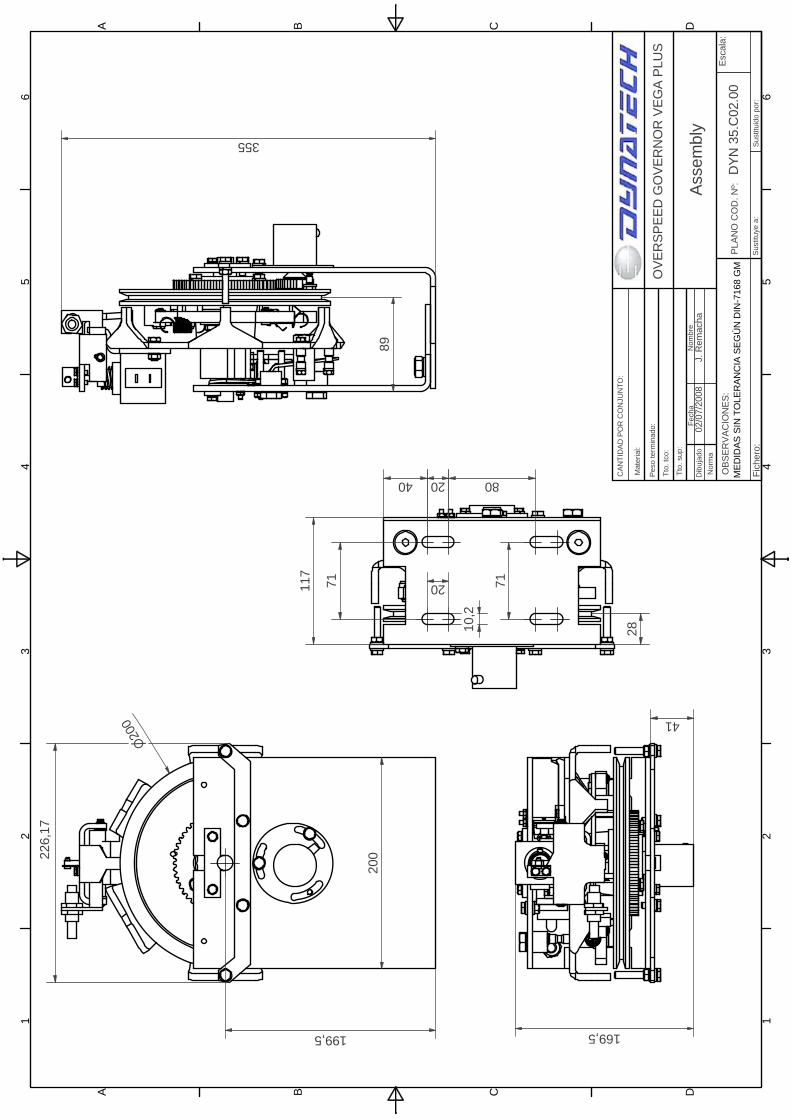
10 INSTALLATION DRAWINGS
The following drawings may be of help when adapting and installing the VEGA / VEGA PLUS overspeed governor:
Note: This manual displays partial information on the instructions for use and maintenance of this product. Please refer to the customer area in Dynatech’s website in order to consult the full manual; http://customers.dynatech-elevation.com/

1 1
2 2
3 3
4 4
5 5
6 6
AA
BB
CC
DD
PLA
NO
CO
D. N
º:VE
GA
Escala
:
VE
GA
CO
NJU
NT
O:
Sustitu
ye a
:S
ustitu
ido p
or:
O
BS
ER
VA
CIO
NE
S:
Mate
rial:
Pe
so te
rmin
ado
:
Tto
. tc
o:
Tto
. sup
:
Fic
hero
:
Fecha
Nom
bre
Dib
uja
do
Norm
a
18/1
0/1
1V
. N
avaz
CA
NT
IDA
D P
OR
CO
NJU
NT
O:
350
222
137
117
28
199,5
10,2
80
200
20
20
71
31.5
27
23
200
5
80
1 1
2 2
3 3
4 4
5 5
6 6
AA
BB
CC
DD
ME
DID
AS
SIN
TO
LE
RA
NC
IA S
EG
ÚN
DIN
-7168 G
MP
LA
NO
CO
D. N
º:Assem
bly
Escala
:
OV
ER
SP
EE
D G
OV
ER
NO
R V
EG
A P
LU
S
Sustitu
ye a
:S
ustitu
ido p
or:
DY
N 3
5.C
02.0
0O
BS
ER
VA
CIO
NE
S:
Mate
rial:
Pe
so te
rmin
ado
:
Tto
. tc
o:
Tto
. sup
:
Fic
hero
:
Fecha
Nom
bre
Dib
uja
do
Norm
a
02/0
7/2
008
J. R
em
acha
CA
NT
IDA
D P
OR
CO
NJU
NT
O:
200
199,5
355
10,2
71
28
117
71
2040 80
20
169,5
4189
200226,1
7