Embed Size (px)
Citation preview
IntroductionThe FF-4 is a 2 1/4” sunlight readable color display instrument intended for efficient monitoring of fuel related informationfor single or dual fuel tanks. The FF-4 has many display configurations based on single/dual flow senders, single/duallevel senders and a fuel pressure sender.
Full functionality is available with a fuel flow and level sender or only with a fuel flow sender using calculated fuel levelsbased on fuel usage. Differential fuel flow calculations are also supported for fuel return systems. Fuel injector systemsare also supported. Standard automotive fuel level senders can be used, even with odd shaped tanks due to acomprehensive, multi-point calibration system. Most fuel flow senders can be used as the K-factor of the sender can beentered into the system for simple calibration.
MGL Avionics supplies a lightweight dual range fuel flow sender that is ideally suited for the FF-4. Fuel flow senders fromother manufactures (e.g. Floscan) are equally suitable.
In addition, the FF-4 can use the actual ground speed from a RS232 NMEA enabled GPS receiver to determine fuelrange.
The FF-4 can also be interfaced via the CAN bus to an external RDAC unit (Remote Data Acquisition Computer). Thisallows for easier installation as the RDAC unit is normally mounted in the engine compartment.
Vega FF-4Fuel Computer
Operating Manual – English 1.03
Vega FF-4 Operating Manual Page 2
1 Features• 1.8” high resolution 160x128, sunlight readable, wide viewing angle, 1000 cd/m2 TFT LCD display• Advanced fuel computer with various modes of operation• Supports single or dual fuel tanks• The FF-4 can connect to one or two fuel flow senders, fuel level senders or fuel injectors• The FF-4 can connect to a single fuel pressure sender• Differential fuel flow calculations are also supported for fuel return systems• The FF-4 has the ability to connect to a NMEA enabled RS232 GPS receiver for range based calculations. It
can also accept a manually entered estimate cruising speed if a GPS is not available.• Standard automotive fuel level senders can be used, even with odd shaped tanks due to a comprehensive,
multi-point calibration system• External RDAC (Remote Data Acquisition Computer) interfacing via the CAN bus• Standard 2 1/4” aircraft enclosure (can be front or rear mounted)• Rotary control plus 2 independent buttons for easy menu navigation and user input• An external output activates when an alarm condition has been reached• Wide input supply voltage range of 8 to 30V DC with built in voltage reversal and over voltage protection
for harsh electrical environments• 1 year limited warranty
2 Layout
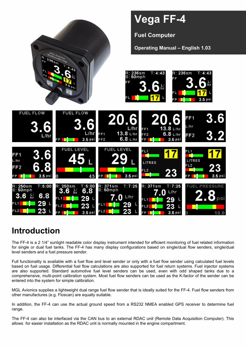
F2 / Down Button:Menu System: Softkey buttonNormal Display: Manually enter your current fuel level after fueling or defueling your aircraft (Mode dependent)
Sunlight readable color graphic display:Backlight can be adjusted in the menu system
Rotary Control (Up/Down) & Enter Button:Press the rotary control during the normal display screens to access the menu system.Rotate anti/clockwise for up/down menu scrolling. Rotate the rotary control during thenormal display mode to view the fuel totals display.
F1 / Up Button:Menu System: Softkey buttonNormal Display: Manual speed Input. (Mode dependent)
2 1/4” enclosure.Can be front or rear mounted
Vega FF-4 Operating Manual Page 3
3 Main DisplaysThe FF-4 has various display screens depending on the mode selected.
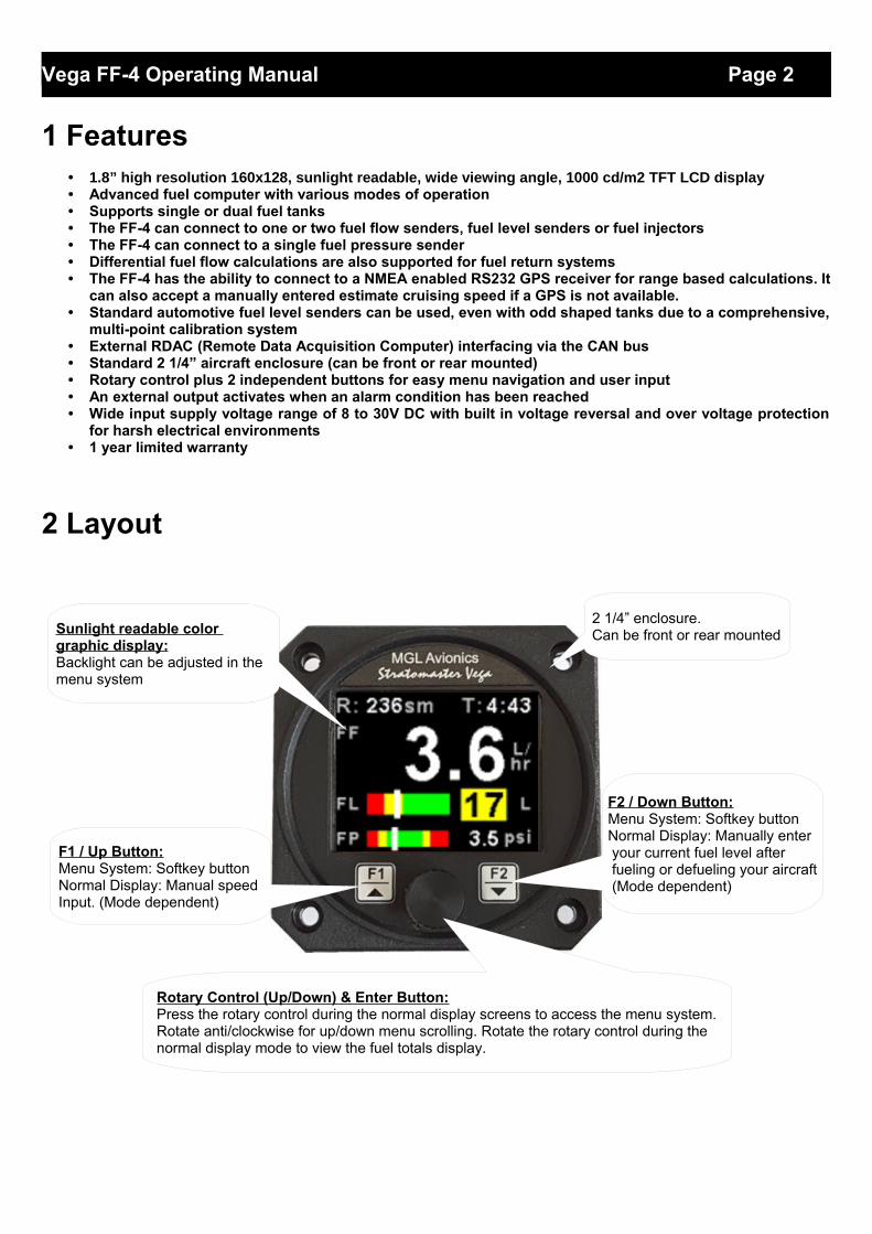
3.1 Single fuel flow and calculated tank level (single tank) Single fuel flow and fuel level sender (single tank) Differential fuel flow and calculated tank level (single tank) Differential fuel flow and fuel level sender (single tank) Summed fuel flow and calculated tank level (single tank) Summed fuel flow and fuel level sender (single tank)
3.2 Dual fuel flow and calculated tank levels (dual tank) Dual fuel flow and dual fuel level senders (dual tank)
Fuel range
Fuel endurancehours:minutes
Fuel flow
Fuel flow unit
Fuel level unit
Fuel level
SpeedWhite:Manual SpeedMagenta:GPS ground speed
Fuel pressure unitFuel pressure
Fuel level 2
Fuel level 1
Fuel pressureFuel pressure unit
Fuel level unit
Fuel flow unit
Fuel flow 2Fuel flow 1
SpeedWhite:Manual SpeedMagenta:GPS ground speed
Fuel endurancehours:minutes
Fuel range
Speed / Fuel range will alternateWhite:Manual SpeedMagenta:GPS ground speed
Speed / Fuel range will alternateWhite:Manual SpeedMagenta:GPS ground speed
Vega FF-4 Operating Manual Page 4
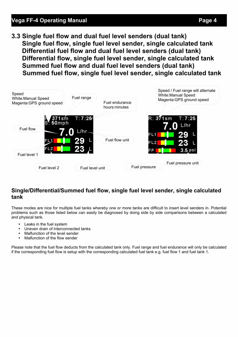
3.3 Single fuel flow and dual fuel level senders (dual tank) Single fuel flow, single fuel level sender, single calculated tank Differential fuel flow and dual fuel level senders (dual tank) Differential flow, single fuel level sender, single calculated tank Summed fuel flow and dual fuel level senders (dual tank) Summed fuel flow, single fuel level sender, single calculated tank
Single/Differential/Summed fuel flow, single fuel level sender, single calculated tank
These modes are nice for multiple fuel tanks whereby one or more tanks are difficult to insert level senders in. Potentialproblems such as those listed below can easily be diagnosed by doing side by side comparisons between a calculatedand physical tank.
• Leaks in the fuel system• Uneven drain of interconnected tanks• Malfunction of the level sender• Malfunction of the flow sender
Please note that the fuel flow deducts from the calculated tank only. Fuel range and fuel endurance will only be calculatedif the corresponding fuel flow is setup with the corresponding calculated fuel tank e.g. fuel flow 1 and fuel tank 1.
Fuel pressure unitFuel pressure
Speed / Fuel range will alternateWhite:Manual SpeedMagenta:GPS ground speedFuel range
Fuel endurancehours:minutes
Fuel flow
SpeedWhite:Manual SpeedMagenta:GPS ground speed
Fuel level 1
Fuel level 2 Fuel level unit
Fuel flow unit
Vega FF-4 Operating Manual Page 5
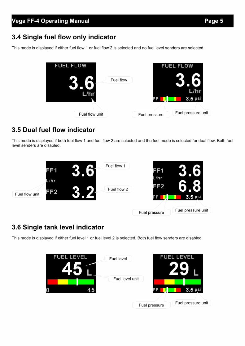
3.4 Single fuel flow only indicator
This mode is displayed if either fuel flow 1 or fuel flow 2 is selected and no fuel level senders are selected.
3.5 Dual fuel flow indicator
This mode is displayed if both fuel flow 1 and fuel flow 2 are selected and the fuel mode is selected for dual flow. Both fuellevel senders are disabled.
3.6 Single tank level indicator
This mode is displayed if either fuel level 1 or fuel level 2 is selected. Both fuel flow senders are disabled.
Fuel pressure Fuel pressure unitFuel flow unit
Fuel flow
Fuel pressure Fuel pressure unit
Fuel flow unit
Fuel flow 1
Fuel flow 2
Fuel pressure Fuel pressure unit
Fuel level
Fuel level unit
Vega FF-4 Operating Manual Page 6
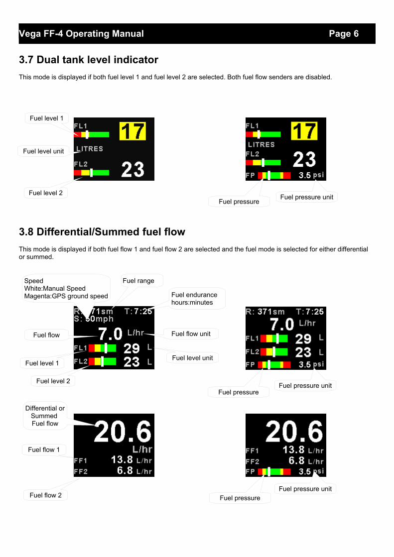
3.7 Dual tank level indicator
This mode is displayed if both fuel level 1 and fuel level 2 are selected. Both fuel flow senders are disabled.
3.8 Differential/Summed fuel flow
This mode is displayed if both fuel flow 1 and fuel flow 2 are selected and the fuel mode is selected for either differential or summed.
Fuel pressureFuel pressure unit
Fuel level 1
Fuel level 2
Fuel level unit
Fuel pressureFuel pressure unit
Fuel level 2
Fuel level 1Fuel level unit
Fuel flow Fuel flow unit
SpeedWhite:Manual SpeedMagenta:GPS ground speed
Fuel range
Fuel endurancehours:minutes
Differential orSummed Fuel flow
Fuel flow 1
Fuel flow 2 Fuel pressureFuel pressure unit
Vega FF-4 Operating Manual Page 7
3.9 Enter cruising speed (Mode dependent)
Press the F1 key during the main display screen to manually enter your aircraft’s cruisingspeed. This value will be used to calculate the fuel range, i.e. how far you can fly with theremaining fuel at zero wind speed. For this calculation, your current remaining fuel, your current fuel flow and the speed entered here are taken into account. You can easily change the speed during flight to reflect changes in ground speed or cruising speed. Usethis function with care and do not use it to extend your range. You must at all times have a secondary indication of available fuel. Note that flow senders and level senders may besubject to malfunction that may result in incorrect fuel levels being displayed or calculated. This function is only available in certain display modes.
3.10 Enter starting level of fuel tanks (Mode dependent)
Press the F2 key during the main display screen to manually enter your current fuel level after fueling or defueling your aircraft. This function is only available if you have a mode selected where fuel level is calculated from fuel flow. Press the F2 key again as a “quickfill button” to the full level.
Note:It is good airmanship to take into account a “silent” fuel reserve. For example, if youhave a 50 Litre tank and you fill it, enter 40 or 45 Litres as your available fuel.
3.11 Fuel Totals (Mode dependent)
This display can be accessed by rotating the rotary control during the normal displaymode. Press the F1/Up button when the fuel totals display is showing to reset the totalisers.
These are 2 independent accumulators for fuel tank 1 and fuel tank 2 that totalize the amount of fuel burn since the last time the accumulators were reset to zero.
3.12 Incorrect fuel setup message
The following message will be displayed if the FF-4 is incorrectly setup. For example if both fuel flow senders are disabled and a single/dual fuel level(s) are setup for calculatedfuel tanks.
Vega FF-4 Operating Manual Page 8
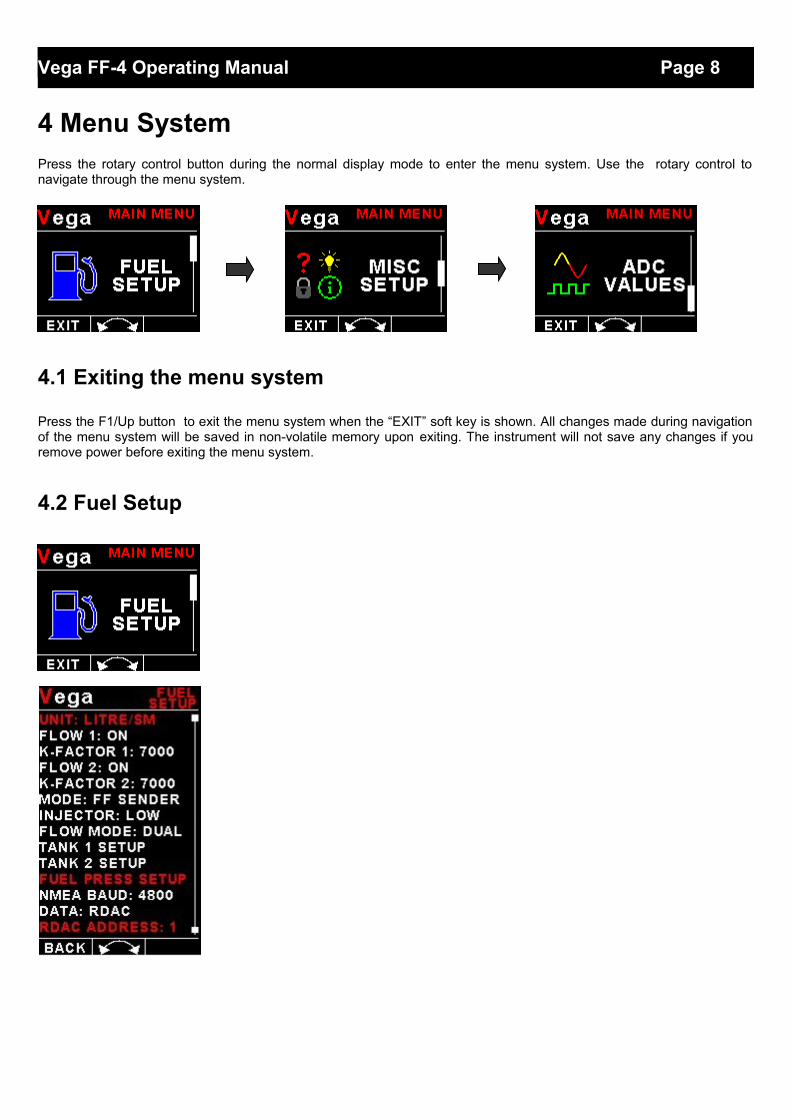
4 Menu SystemPress the rotary control button during the normal display mode to enter the menu system. Use the rotary control tonavigate through the menu system.
4.1 Exiting the menu system
Press the F1/Up button to exit the menu system when the “EXIT” soft key is shown. All changes made during navigationof the menu system will be saved in non-volatile memory upon exiting. The instrument will not save any changes if youremove power before exiting the menu system.
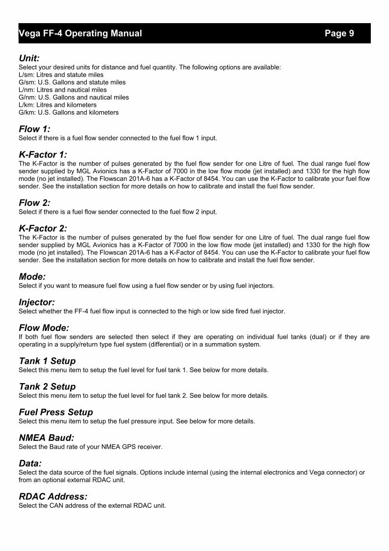
4.2 Fuel Setup
Vega FF-4 Operating Manual Page 9
Unit:Select your desired units for distance and fuel quantity. The following options are available:L/sm: Litres and statute miles G/sm: U.S. Gallons and statute milesL/nm: Litres and nautical milesG/nm: U.S. Gallons and nautical milesL/km: Litres and kilometersG/km: U.S. Gallons and kilometers
Flow 1:Select if there is a fuel flow sender connected to the fuel flow 1 input.
K-Factor 1:The K-Factor is the number of pulses generated by the fuel flow sender for one Litre of fuel. The dual range fuel flowsender supplied by MGL Avionics has a K-Factor of 7000 in the low flow mode (jet installed) and 1330 for the high flowmode (no jet installed). The Flowscan 201A-6 has a K-Factor of 8454. You can use the K-Factor to calibrate your fuel flowsender. See the installation section for more details on how to calibrate and install the fuel flow sender.
Flow 2:Select if there is a fuel flow sender connected to the fuel flow 2 input.
K-Factor 2:The K-Factor is the number of pulses generated by the fuel flow sender for one Litre of fuel. The dual range fuel flowsender supplied by MGL Avionics has a K-Factor of 7000 in the low flow mode (jet installed) and 1330 for the high flowmode (no jet installed). The Flowscan 201A-6 has a K-Factor of 8454. You can use the K-Factor to calibrate your fuel flowsender. See the installation section for more details on how to calibrate and install the fuel flow sender.
Mode:Select if you want to measure fuel flow using a fuel flow sender or by using fuel injectors.
Injector:Select whether the FF-4 fuel flow input is connected to the high or low side fired fuel injector.
Flow Mode:If both fuel flow senders are selected then select if they are operating on individual fuel tanks (dual) or if they areoperating in a supply/return type fuel system (differential) or in a summation system.
Tank 1 SetupSelect this menu item to setup the fuel level for fuel tank 1. See below for more details.
Tank 2 SetupSelect this menu item to setup the fuel level for fuel tank 2. See below for more details.
Fuel Press SetupSelect this menu item to setup the fuel pressure input. See below for more details.
NMEA Baud:Select the Baud rate of your NMEA GPS receiver.
Data:Select the data source of the fuel signals. Options include internal (using the internal electronics and Vega connector) or from an optional external RDAC unit.
RDAC Address:Select the CAN address of the external RDAC unit.
Vega FF-4 Operating Manual Page 10
4.2.1 Tank 1 / 2 Setup menu
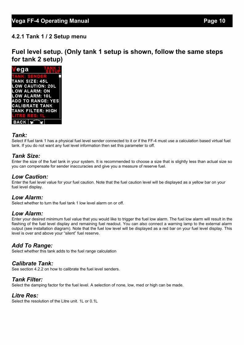
Fuel level setup. (Only tank 1 setup is shown, follow the same steps for tank 2 setup)
Tank:Select if fuel tank 1 has a physical fuel level sender connected to it or if the FF-4 must use a calculation based virtual fuel tank. If you do not want any fuel level information then set this parameter to off.
Tank Size:Enter the size of the fuel tank in your system. It is recommended to choose a size that is slightly less than actual size soyou can compensate for sender inaccuracies and give you a measure of reserve fuel.
Low Caution:Enter the fuel level value for your fuel caution. Note that the fuel caution level will be displayed as a yellow bar on your fuel level display.
Low Alarm:Select whether to turn the fuel tank 1 low level alarm on or off.
Low Alarm:Enter your desired minimum fuel value that you would like to trigger the fuel low alarm. The fuel low alarm will result in theflashing of the fuel level display and remaining fuel readout. You can also connect a warning lamp to the external alarmoutput (see installation diagram). Note that the fuel low level will be displayed as a red bar on your fuel level display. Thislevel is over and above your “silent” fuel reserve.
Add To Range:Select whether this tank adds to the fuel range calculation
Calibrate Tank:See section 4.2.2 on how to calibrate the fuel level senders.
Tank Filter:Select the damping factor for the fuel level. A selection of none, low, med or high can be made.
Litre Res:Select the resolution of the Litre unit. 1L or 0.1L
Vega FF-4 Operating Manual Page 11
4.2.2 Calibrating the fuel level senders
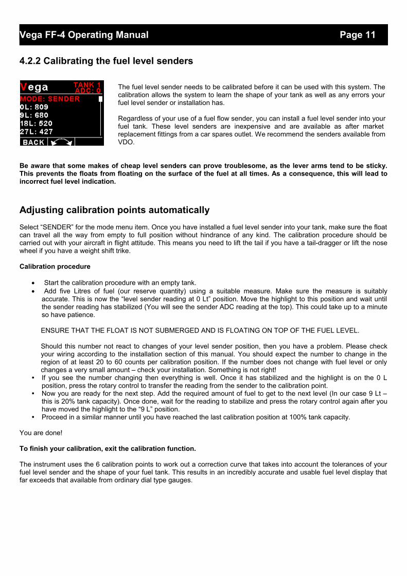
The fuel level sender needs to be calibrated before it can be used with this system. The calibration allows the system to learn the shape of your tank as well as any errors your fuel level sender or installation has.
Regardless of your use of a fuel flow sender, you can install a fuel level sender into your fuel tank. These level senders are inexpensive and are available as after market replacement fittings from a car spares outlet. We recommend the senders available from VDO.
Be aware that some makes of cheap level senders can prove troublesome, as the lever arms tend to be sticky.This prevents the floats from floating on the surface of the fuel at all times. As a consequence, this will lead toincorrect fuel level indication.
Adjusting calibration points automatically
Select “SENDER” for the mode menu item. Once you have installed a fuel level sender into your tank, make sure the floatcan travel all the way from empty to full position without hindrance of any kind. The calibration procedure should becarried out with your aircraft in flight attitude. This means you need to lift the tail if you have a tail-dragger or lift the nosewheel if you have a weight shift trike.
Calibration procedure
Start the calibration procedure with an empty tank. Add five Litres of fuel (our reserve quantity) using a suitable measure. Make sure the measure is suitably
accurate. This is now the “level sender reading at 0 Lt” position. Move the highlight to this position and wait untilthe sender reading has stabilized (You will see the sender ADC reading at the top). This could take up to a minuteso have patience.
ENSURE THAT THE FLOAT IS NOT SUBMERGED AND IS FLOATING ON TOP OF THE FUEL LEVEL.
Should this number not react to changes of your level sender position, then you have a problem. Please checkyour wiring according to the installation section of this manual. You should expect the number to change in theregion of at least 20 to 60 counts per calibration position. If the number does not change with fuel level or onlychanges a very small amount – check your installation. Something is not right!
• If you see the number changing then everything is well. Once it has stabilized and the highlight is on the 0 Lposition, press the rotary control to transfer the reading from the sender to the calibration point.
• Now you are ready for the next step. Add the required amount of fuel to get to the next level (In our case 9 Lt –this is 20% tank capacity). Once done, wait for the reading to stabilize and press the rotary control again after youhave moved the highlight to the “9 L” position.
• Proceed in a similar manner until you have reached the last calibration position at 100% tank capacity.
You are done!
To finish your calibration, exit the calibration function.
The instrument uses the 6 calibration points to work out a correction curve that takes into account the tolerances of yourfuel level sender and the shape of your fuel tank. This results in an incredibly accurate and usable fuel level display thatfar exceeds that available from ordinary dial type gauges.
Vega FF-4 Operating Manual Page 12
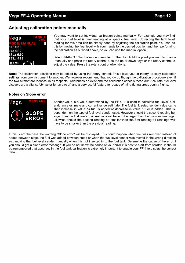
Adjusting calibration points manually
You may want to set individual calibration points manually. For example you may find that your fuel level is over reading at a specific fuel level. Correcting the tank level reading for this area can be simply done by adjusting the calibration point. You can do this by moving the float level with your hands to the desired position and then performing the calibration as outlined above, or you can use the manual option.
Select “MANUAL” for the mode menu item. Then highlight the point you want to change manually and press the rotary control. Use the up or down keys or the rotary control to adjust the value. Press the rotary control when done.
Note: The calibration positions may be edited by using the rotary control. This allows you, in theory, to copy calibrationsettings from one instrument to another. We however recommend that you do go though the calibration procedure even ifthe two aircraft are identical in all respects. Tolerances do exist and the calibration cancels these out. Accurate fuel leveldisplays are a vital safety factor for an aircraft and a very useful feature for peace of mind during cross county flights.
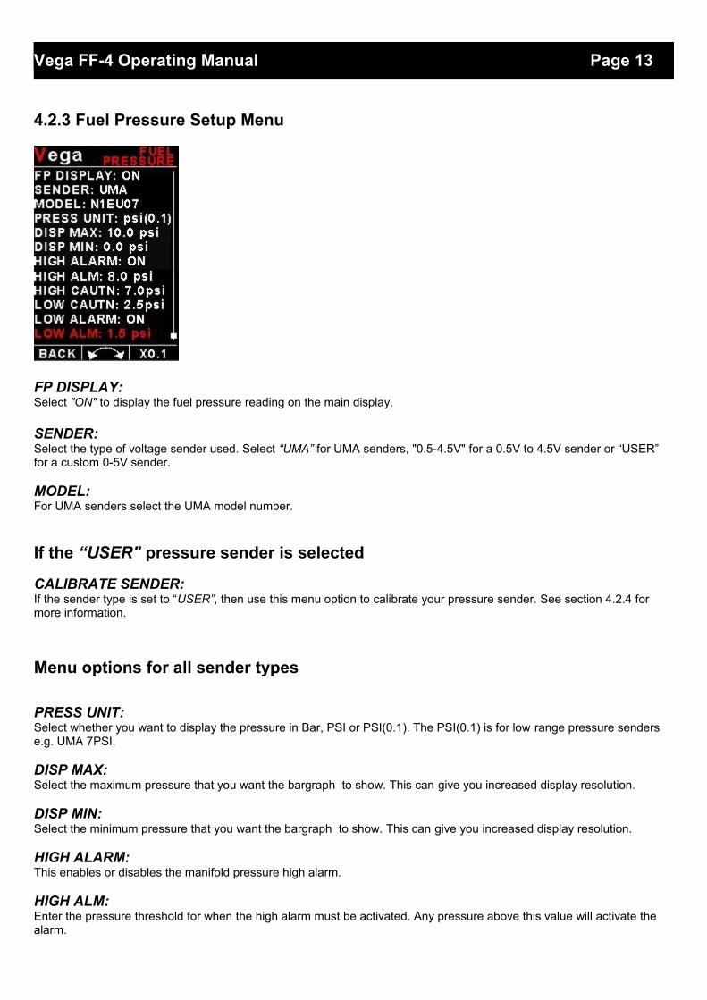
Notes on Slope error
Sender value is a value determined by the FF-4. It is used to calculate fuel level, fuel endurance estimate and current range estimate. The fuel tank setup sender value can either increase in value as fuel is added or decrease in value if fuel is added. This is dependent on the type of fuel level sender used. However should the second reading be larger than the first reading all readings will have to be larger than the previous readings. Likewise should the second reading be smaller than the first reading all readings will have to be smaller than the previous reading.
If this is not the case the wording "Slope error" will be displayed. This could happen when fuel was removed instead ofadded between steps, no fuel was added between steps or when the fuel level sender was moved in the wrong directione.g. moving the fuel level sender manually when it is not inserted in to the fuel tank. Determine the cause of the error ifyou should get a slope error message. If you do not know the cause of your error it is best to start from scratch. It shouldbe remembered that accuracy in the fuel tank calibration is extremely important to enable your FF-4 to display the correctdata.
Vega FF-4 Operating Manual Page 13
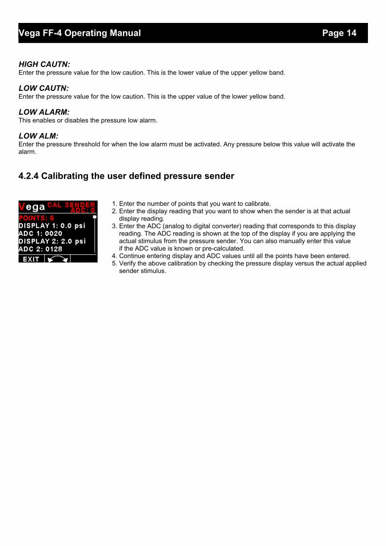
4.2.3 Fuel Pressure Setup Menu
FP DISPLAY:Select "ON" to display the fuel pressure reading on the main display.
SENDER:Select the type of voltage sender used. Select “UMA” for UMA senders, "0.5-4.5V" for a 0.5V to 4.5V sender or “USER” for a custom 0-5V sender.
MODEL:For UMA senders select the UMA model number.
If the “USER" pressure sender is selected
CALIBRATE SENDER:If the sender type is set to “USER”, then use this menu option to calibrate your pressure sender. See section 4.2.4 for more information.
Menu options for all sender types
PRESS UNIT:Select whether you want to display the pressure in Bar, PSI or PSI(0.1). The PSI(0.1) is for low range pressure senders e.g. UMA 7PSI.
DISP MAX:Select the maximum pressure that you want the bargraph to show. This can give you increased display resolution.
DISP MIN:Select the minimum pressure that you want the bargraph to show. This can give you increased display resolution.
HIGH ALARM:This enables or disables the manifold pressure high alarm.
HIGH ALM:Enter the pressure threshold for when the high alarm must be activated. Any pressure above this value will activate the alarm.
Vega FF-4 Operating Manual Page 14
HIGH CAUTN:Enter the pressure value for the low caution. This is the lower value of the upper yellow band.
LOW CAUTN:Enter the pressure value for the low caution. This is the upper value of the lower yellow band.
LOW ALARM:This enables or disables the pressure low alarm.
LOW ALM:Enter the pressure threshold for when the low alarm must be activated. Any pressure below this value will activate the alarm.
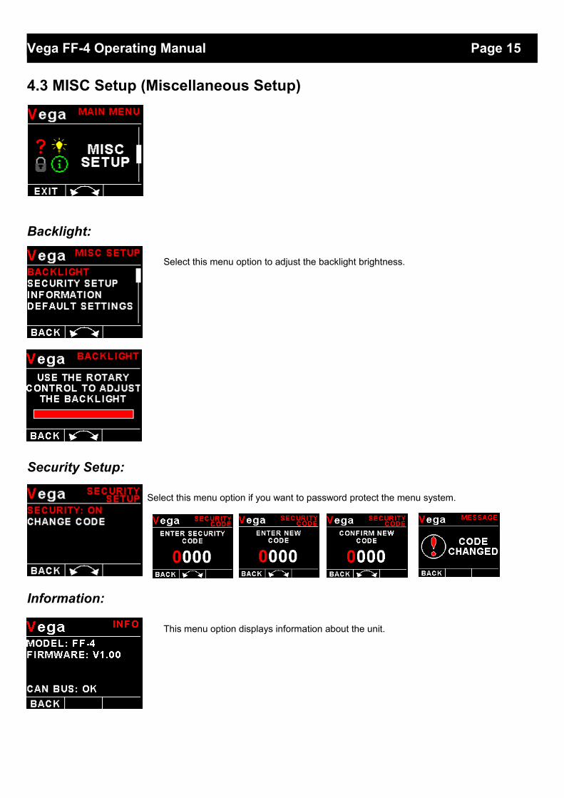
4.2.4 Calibrating the user defined pressure sender
1. Enter the number of points that you want to calibrate.2. Enter the display reading that you want to show when the sender is at that actual display reading.3. Enter the ADC (analog to digital converter) reading that corresponds to this display reading. The ADC reading is shown at the top of the display if you are applying the actual stimulus from the pressure sender. You can also manually enter this value if the ADC value is known or pre-calculated.4. Continue entering display and ADC values until all the points have been entered.5. Verify the above calibration by checking the pressure display versus the actual applied
sender stimulus.
Vega FF-4 Operating Manual Page 15
4.3 MISC Setup (Miscellaneous Setup)
Backlight:
Select this menu option to adjust the backlight brightness.
Security Setup:
Select this menu option if you want to password protect the menu system.
Information:
This menu option displays information about the unit.
Vega FF-4 Operating Manual Page 16
Default Settings:
Select this menu option to reset all the settings to factory defaults.
4.4 ADC Values
This menu displays the ADC values of the two fuel level and pressure sender.
5 Loading factory default settings
Press and hold the F1/Up button and rotary control during power up to load the pre-programmed factory default settings. The following screen will be displayed:
Factory default settings can also be loaded in the Miscellaneous setup menu.
6 Error Messages
Unit settings CRC error. Load default settings to restore to factory defaults. If the error message still persists then it could possibly be a non-volatile memory failure in which case the instrument will then have to be returned to the factory.
Internal flash CRC error. The instrument does a firmware check on the program when power is applied to the instrument . If the program is corrupt in any way then the internal flash CRC error will be displayed. Reload the instruments firmware and load default settings. If the error message still persists then it could possibly be an internal flash memory failure in which case the instrument will then have to be returned to the factory.
Fuel Data CRC error. The instrument could possibly have a non-volatile memory failure in which case the instrument will then have to be returned to the factory.
Vega FF-4 Operating Manual Page 17
The red cross over the display means the FF-4 has lost communications with the external RDAC unit. Check the wiring between the FF-4 instrument and the RDAC unit. This error message is only available when the external RDAC is selected as the fuel data source.
7 SpecificationsOperating Temperature Range -10ºC to 60ºC (14ºF to 140ºF)Storage Temperature Range -20ºC to 80ºC (-4ºF to 176ºF)Humidity <85% non-condensing
Power Supply8 to 30Vdc SMPS (switch mode power supply) with built in 33V over voltage and reverse voltage protection
Current ConsumptionApprox. 73mA @ 13.8V (backlight highest setting), 33mA @13.8V (backlight lowest setting)
Display
1.8” 160x128 pixel active matrix TFT display.1000 cd/m2Sunlight readable with anti-glare coatingLED Backlight is user configurable
Alarm OutputOpen collector transistor switch to groundMaximum rating 0.25A
ADC 12 bitDimensions see Vega series dimensional drawingEnclosure 2 1/4” ABS, black in color, front or rear mounting. Flame retardant.Weight Approx. 120 grams (Instrument excluding cables)Non-volatile memory storage 100000 write cyclesFuel level input Maximum voltage: 5V, 5mA maximum current
Fuel level senders supportedAny resistive type with common ground and capacitive probes with active voltage outputs up to 5V level (push pull or pullup)
Fuel flow sendersSupply 5V, 40mA maximum current. TTL level input with noise filter andSchmitt-trigger hysteresis. Required input voltage swing: less than 1.5V to more than 3.5V. Maximum input voltage range -5V to +18V
Fuel pressure senders
UMA N1EU07G(M): 7PSI (0.5Bar) for carburated engine (Rotax) UMA N1EU35G(M): 35PSI (2.4Bar) for carburated engine (Lycoming/Continental) UMA N1EU100G(M): 100PSI (6.9Bar) for injected (Lycoming/Continental) (M) is MGL modified senders
NMEA Baud rate Selectable 1200 to 115200 baud
8 Operating the alarmsThe alarm output can be used to switch an external alarm indicator. The external alarm switch is an open collectortransistor switch to ground with a maximum rating of 0.25A DC. It is possible to wire the alarm contacts of severalStratomaster instruments in parallel should this be desired. To avoid false activation of the alarms, the alarm function isonly active 10 seconds after the instrument has powered up.
9 Firmware Upgrading
The FF-4 can be upgraded in the field by connecting the RS232 port to a PC and running the firmware update program.Note that only the RS232 port can be used to upgrade the firmware.
Please see the Vega firmware upgrading document for more information.
Vega FF-4 Operating Manual Page 18
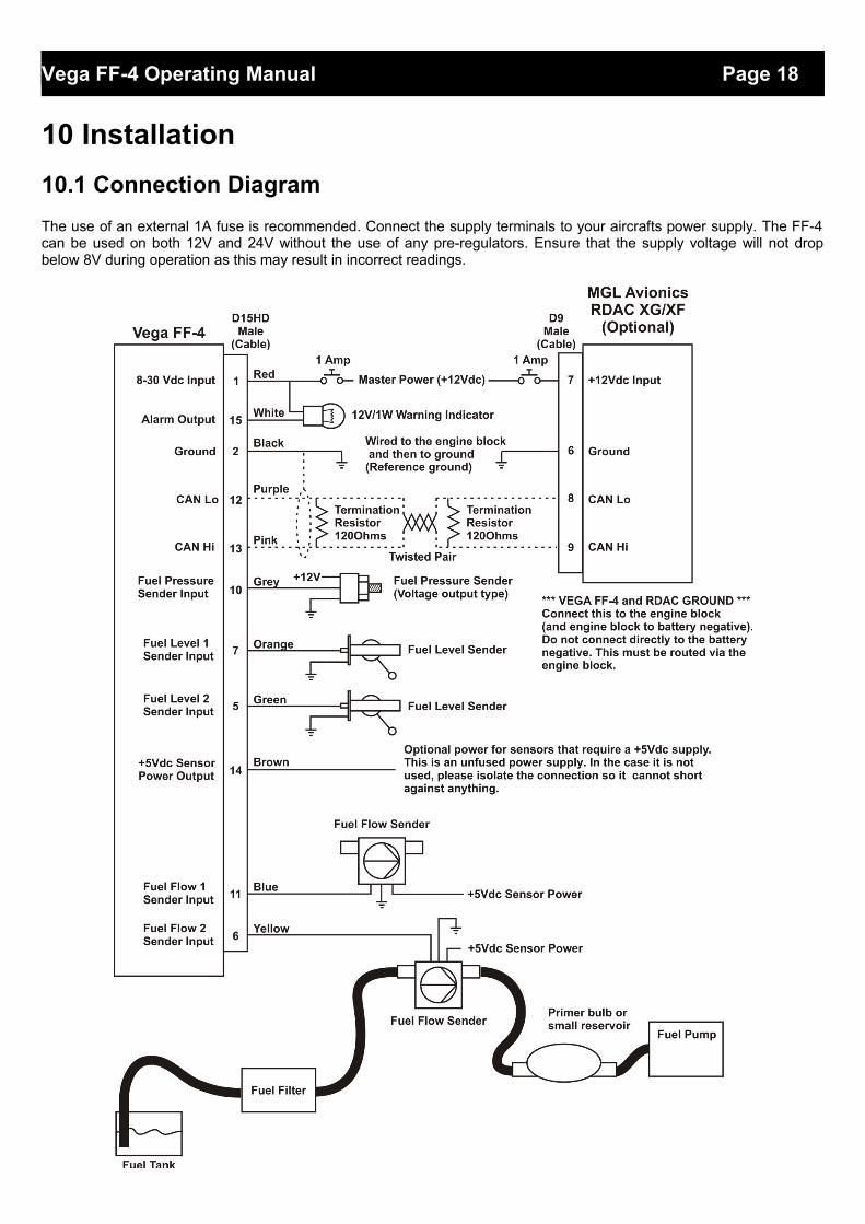
10 Installation
10.1 Connection Diagram
The use of an external 1A fuse is recommended. Connect the supply terminals to your aircrafts power supply. The FF-4can be used on both 12V and 24V without the use of any pre-regulators. Ensure that the supply voltage will not dropbelow 8V during operation as this may result in incorrect readings.

Vega FF-4 Operating Manual Page 19
10.2 Fuel flow sender installation
The fuel flow sender allows the FF-4 to provide instantaneous readouts of hourly fuel usage, and both time and distanceestimates on remaining fuel in flight. You can also verify the performance of your fuel pump during the pre-takeoff enginerun up – a very valuable check! Further, it is possible to set up the instruments to calculate fuel remaining by subtractingfuel used from a value entered when you filled your tank(s). In this case you may omit the installation of the optional fuellevel sender. Please note that the installation of the fuel Flow sender should be done in such a fashion that dirt ordebris from the fuel tank cannot lodge inside the flow sender. These will not block you fuel flow but may lead tothe impeller inside the sender jamming. It is usually sufficient to mount the flow sender AFTER the fuel filter butbefore the fuel pump. It is a good idea to provide a small reservoir such as a primer bulb between the flow senderand the fuel pump.
As indicated in the recommended installation drawing, it can be of advantage to install the flow sender in such a fashionthat the inlet points slightly down and the outlet points slightly up. This prevents vapor from forming a bubble inside theflow sender. We strongly recommend mounting the flow sender in such a fashion that the impeller rests on only onebearing. This is achieved if you mount the sender such that the surface with the arrow faces upwards. Mounting thesender like this results in the best performance at low flow rates as only very little friction is present. The flow sender isdelivered with a small jet that can be installed in the flow sender inlet. Installation of this jet is recommended for engineswith fuel flow rates lower than about 30 Litres per hour. This would apply to most small two and four stroke engines. TheFF-4 is shipped with the fuel flow sender calibration set for the jet installed. In a good installation you can expect about +/-3% maximum flow reading error with this factor. You can calibrate the flow sender yourself to a higher degree of accuracyif you so desire.
Recommended procedure to calibrate the fuel flow sender:
Note: You must disable the fuel level sender if you have one installed, and enable the calculated fuel level sender.
1. Fill your tank exactly to a known level (for example 50 Litres).2. Set your fuel level to 50 Litres.3. Fly your aircraft for a period that you know will use approximately 20 Litres of fuel. The exact fuel burn is not
important; just burn about 20 Litres of your fuel. At the end of your flight the instrument should give you a readingof how much fuel you have left – the reading should be about 30 Litres left.
4. Now place your aircraft in exactly the same position that you used when you first filled the tank and refill the tankto 50 Litres using a measuring jug. You should find that you need 20 Litres of fuel to refill to 50 Litres.
5. If you find that the instrument under or over reads the fuel used, you should perform a simple adjustment of thefuel flow sender calibration factor.
Example:Actual fuel used: 21.5 Litres, FF-4 fuel burn calculated 29.7 Litres left in the tank. This means the FF-4 measured 50-29.7= 20.3 Litres. We are under reading by 1.2 Litres.
Default calibration factor in Fuel setup menu = 7000.
Let the corrected calibration factor be X.X = (20.3 * 7000) / 21.5X = 6609.3
The closest setting you can enter as factor is 6609. Enter it into the unit and you are done!
Repeat the above procedure to verify that your flow sender is now reading correctly.
Please note:Before you calibrate the flow sender ensure there are no problems with your installation. We find the senders are veryaccurate if everything is installed and working properly. If your fuel burn indication is out by a large amount you have aproblem that you should not attempt to fix by fiddling with the calibration factor! Please ensure that no fuel vapor can betrapped inside the sender housing in the form of bubbles. Due to the low fuel flow rates the bubbles will prevent the tinyimpeller from turning freely, you can verify the turning of the impeller. You should notice three dark spots that are justvisible in the inside of the fuel flow sender. These are small magnets that are attached to the impeller. With fuel flowingyou should see the magnets turning. The best defense against vapor bubbles is to install the flow sender in such a way

Vega FF-4 Operating Manual Page 20
that the bubbles can escape. The easiest way is to point the outlet slightly upwards and the inlet (with the jet) slightlydownwards. Another possible problem is the fuel sender jet. When you install it, do not damage it. Use a drill bit ofsuitable diameter (5.5mm) to push the jet all the way, the opening of the jet must be just in front of the impeller.
YOU NEED TO APPLY SOME FORCE TO INSERT THE JET ALL THE WAY (about 24mm). THE JET MUST BELOCATED RIGHT IN FRONT OF THE IMPELLOR. YOU CANNOT PUSH THE JET TOO FAR.
Using other Flow Senders
It is quite possible to use flow senders other than the MGL Avionics fuel flow sender. In this case ensure that the sender outputs a 5V TTL square wave or a similar signal. The FF-4 interface electronics will adapt to a variety of different voltages and pulse shapes as it contains a Schmitt-trigger input stage. The calibration factor can be entered in a wide range making the unit particularly suited to other flow senders. The supply output terminal for the sender provides a positive, regulated 5 volt output. This may be used to power the flow sender provided the sender will not draw more than 40 mA of current. Should your sender require a higher voltage or more current, you must supply the sender from a different power source. Exceeding the rating on the MGL Avionics fuel flow sender supply terminal can affect the operation on the unit negatively or even damage it. Some senders require a pull-up resistor to the 12V supply line. We find most installations of these senders require a 4K7 pull-up resistor.
Recommended Calibration Factors for the MGL Avionics dual range flow sender:
With jet installed = 7000. Recommended for flow rates below 30 Litres/hour maximumWithout jet installed = 1330. Recommended for flow rates above 30 Litres/hour
Please refer to the leaflet included with the flow sender for information on pressure drop versus flow rate, wetted materialsetc.
It is your responsibility to ensure that the flow sender used is compatible with the fuels youintend using. We have found the MGL Avionics fuel flow sender to be very compatible withautomotive fuels used in South Africa, many of which contain methanol. 100LL AVGAS alsoappears not to harm the sender in any way. We have exposed a sender continuously to ourautomotive fuels for the duration of two years without any noticeable ill effect on the sender.However, despite this MGL Avionics or its appointed agents cannot assume responsibility forany incident or damage, even loss of life by whatsoever cause connected with the fuel flowsender or the FF-4 instrument. Usage of this or other senders is your own sole responsibility.
If you do not agree with the above statement you must not use the fuel flow sender.
Note to Pilots: (Even though this is the installation manual)You must always have a visual indication of the fuel level available, either by means of a sight glass, direct tankobservation or a known, reliable secondary fuel level gauge. Fuel level indication by means of calculated fuel burn issubject to errors both by entering incorrect starting fuel levels as well as mechanical problems causing the flow senderimpeller to turn too slowly, resulting in under reading fuel burn and thus over reading remaining fuel. As pilot in commandof an aircraft it is your responsibility to ensure that you have sufficient fuel to reach your intended destination. Alwaysensure that you have a generous amount of reserve fuel and never use your reserve fuel except in an emergency if it isunavoidable.
Vega FF-4 Operating Manual Page 21
10.3 Floscan 201 fuel flow sender installation
1. The inlet and outlet ports in series 201 flow transducers have ¼” NPT threads. Use only ¼” NPT hose or pipefittings to match. When assembling fittings into the inlet and outlet ports DO NOT EXCEED a torque of 15 ft. lbs.(180 inch lbs.), or screw the fittings in more than 2 full turns past hand tight, WHICHEVER COMES FIRST.FloScan Instrument Co., Inc. will not be responsible for cracked castings caused by failure to use ¼” NPT fittings,over torquing the fittings, or assembling them beyond the specified depth.
2. A screen or filter should be installed upstream of the flow transducer to screen out debris which could affect rotormovement or settle in the V-bearings. As turbulence upstream of the transducer affects its performance, thereshould be a reasonable length of straight line between the transducer inlet and the first valve, elbow, or otherturbulence-producing device.
3. Install the flow transducer with wire leads pointed UP to vent bubbles and insure that rotor is totally immersed inliquid. For maximum accuracy at low flow rates the transducer should be mounted on a horizontal surface.
4. Power supply: 12 VDC at 100mA filtered and regulated.5. Series 200 flow transducers are designed to measure steady state flows. Indicated accuracies and pulse counts
were obtained using heptane on a flow stand with rotary pumps and are reproducible in flow systems using rotaryor gear pumps. Fuel systems with diaphragm fuel pumps and carburetors produce pulsating fuel flows. Foraccurate results on these systems consult the factory for the correct flow transducer/pulsation dampercombination.
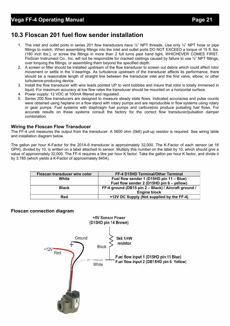
Wiring the Floscan Flow TransducerThe FF-4 unit measures the output from the transducer. A 5600 ohm (5k6) pull-up resistor is required. See wiring tableand installation diagram below.
The gallon per hour K-Factor for the 201A-6 transducer is approximately 32,000. The K-Factor of each sensor (at 16GPH), divided by 10, is written on a label attached to sensor. Multiply this number on the label by 10, which should give avalue of approximately 32,000. The FF-4 requires a litre per hour K factor. Take the gallon per hour K factor, and divide itby 3.785 (which yields a K-Factor of approximately 8454).
Floscan connection diagram
Floscan transducer wire color FF-4 D15HD Terminal/Other TerminalWhite Fuel flow sender 1 (D15HD pin 11 – Blue)
Fuel flow sender 2 (D15HD pin 6 – yellow)Black FF-4 ground (DB15 pin 2 – Black) / Aircraft ground /
Engine blockRed +12V DC Supply (Not supplied by the FF-4)
Vega FF-4 Operating Manual Page 22
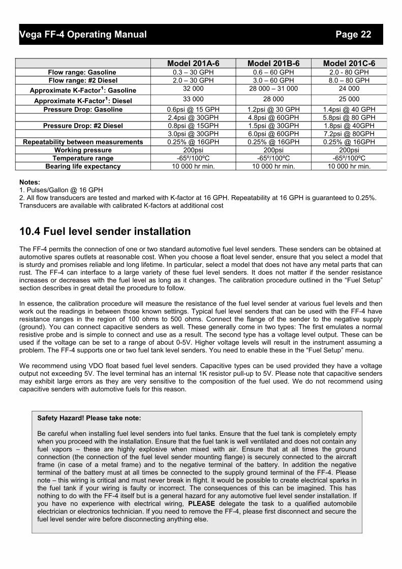
Notes:1. Pulses/Gallon @ 16 GPH2. All flow transducers are tested and marked with K-factor at 16 GPH. Repeatability at 16 GPH is guaranteed to 0.25%. Transducers are available with calibrated K-factors at additional cost
10.4 Fuel level sender installation
The FF-4 permits the connection of one or two standard automotive fuel level senders. These senders can be obtained atautomotive spares outlets at reasonable cost. When you choose a float level sender, ensure that you select a model thatis sturdy and promises reliable and long lifetime. In particular, select a model that does not have any metal parts that canrust. The FF-4 can interface to a large variety of these fuel level senders. It does not matter if the sender resistanceincreases or decreases with the fuel level as long as it changes. The calibration procedure outlined in the “Fuel Setup”section describes in great detail the procedure to follow.
In essence, the calibration procedure will measure the resistance of the fuel level sender at various fuel levels and thenwork out the readings in between those known settings. Typical fuel level senders that can be used with the FF-4 haveresistance ranges in the region of 100 ohms to 500 ohms. Connect the flange of the sender to the negative supply(ground). You can connect capacitive senders as well. These generally come in two types: The first emulates a normalresistive probe and is simple to connect and use as a result. The second type has a voltage level output. These can beused if the voltage can be set to a range of about 0-5V. Higher voltage levels will result in the instrument assuming aproblem. The FF-4 supports one or two fuel tank level senders. You need to enable these in the “Fuel Setup” menu.
We recommend using VDO float based fuel level senders. Capacitive types can be used provided they have a voltageoutput not exceeding 5V. The level terminal has an internal 1K resistor pull-up to 5V. Please note that capacitive sendersmay exhibit large errors as they are very sensitive to the composition of the fuel used. We do not recommend usingcapacitive senders with automotive fuels for this reason.
Model 201A-6 Model 201B-6 Model 201C-6Flow range: Gasoline 0.3 – 30 GPH 0.6 – 60 GPH 2.0 - 80 GPHFlow range: #2 Diesel 2.0 – 30 GPH 3.0 – 60 GPH 8.0 – 80 GPH
Approximate K-Factor¹: Gasoline 32 000 28 000 – 31 000 24 000
Approximate K-Factor¹: Diesel 33 000 28 000 25 000
Pressure Drop: Gasoline 0.6psi @ 15 GPH 1.2psi @ 30 GPH 1.4psi @ 40 GPH2.4psi @ 30GPH 4.8psi @ 60GPH 5.8psi @ 80 GPH
Pressure Drop: #2 Diesel 0.8psi @ 15GPH 1.5psi @ 30GPH 1.8psi @ 40GPH3.0psi @ 30GPH 6.0psi @ 60GPH 7.2psi @ 80GPH
Repeatability between measurements 0.25% @ 16GPH 0.25% @ 16GPH 0.25% @ 16GPHWorking pressure 200psi 200psi 200psi
Temperature range -65º/100ºC -65º/100ºC -65º/100ºCBearing life expectancy 10 000 hr min. 10 000 hr min. 10 000 hr min.
Safety Hazard! Please take note:
Be careful when installing fuel level senders into fuel tanks. Ensure that the fuel tank is completely emptywhen you proceed with the installation. Ensure that the fuel tank is well ventilated and does not contain anyfuel vapors – these are highly explosive when mixed with air. Ensure that at all times the groundconnection (the connection of the fuel level sender mounting flange) is securely connected to the aircraftframe (in case of a metal frame) and to the negative terminal of the battery. In addition the negativeterminal of the battery must at all times be connected to the supply ground terminal of the FF-4. Pleasenote – this wiring is critical and must never break in flight. It would be possible to create electrical sparks inthe fuel tank if your wiring is faulty or incorrect. The consequences of this can be imagined. This hasnothing to do with the FF-4 itself but is a general hazard for any automotive fuel level sender installation. Ifyou have no experience with electrical wiring, PLEASE delegate the task to a qualified automobileelectrician or electronics technician. If you need to remove the FF-4, please first disconnect and secure thefuel level sender wire before disconnecting anything else.
Vega FF-4 Operating Manual Page 23
10.5 Fuel pressure sender installation
Most fuel pressure senders tend to output a voltage level in proportion to the applied pressure. For these devices it is recommended to switch the pull-up resistor off (Dipswitch 3 OFF – Default setting).
UMA N1EU07G(M): 7PSI (0.5Bar) for carburated engine (Rotax) UMA N1EU35G(M): 35PSI (2.4Bar) for carburated engine (Lycoming/Continental) UMA N1EU100G(M): 100PSI (6.9Bar) for injected (Lycoming/Continental)
(M) is MGL modified senders
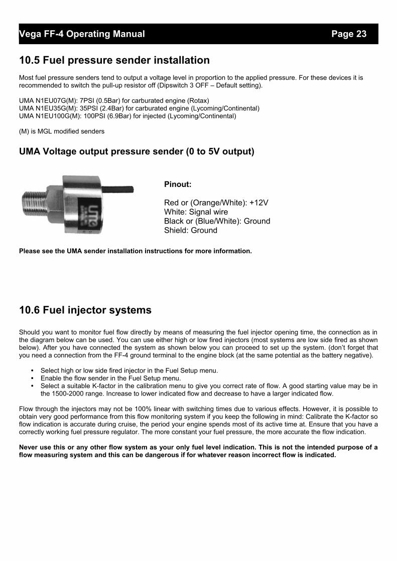
UMA Voltage output pressure sender (0 to 5V output)
Pinout:
Red or (Orange/White): +12VWhite: Signal wireBlack or (Blue/White): GroundShield: Ground
Please see the UMA sender installation instructions for more information.
10.6 Fuel injector systems
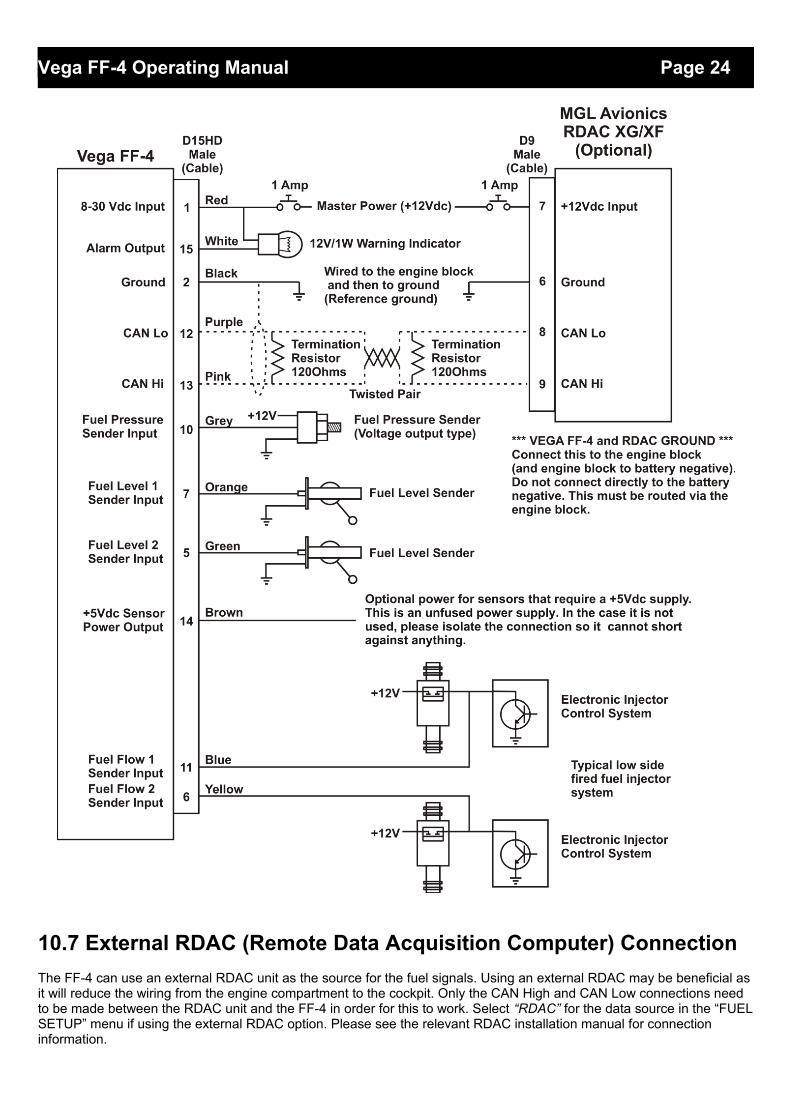
Should you want to monitor fuel flow directly by means of measuring the fuel injector opening time, the connection as inthe diagram below can be used. You can use either high or low fired injectors (most systems are low side fired as shownbelow). After you have connected the system as shown below you can proceed to set up the system. (don’t forget thatyou need a connection from the FF-4 ground terminal to the engine block (at the same potential as the battery negative).
• Select high or low side fired injector in the Fuel Setup menu.• Enable the flow sender in the Fuel Setup menu.• Select a suitable K-factor in the calibration menu to give you correct rate of flow. A good starting value may be in
the 1500-2000 range. Increase to lower indicated flow and decrease to have a larger indicated flow.
Flow through the injectors may not be 100% linear with switching times due to various effects. However, it is possible toobtain very good performance from this flow monitoring system if you keep the following in mind: Calibrate the K-factor soflow indication is accurate during cruise, the period your engine spends most of its active time at. Ensure that you have acorrectly working fuel pressure regulator. The more constant your fuel pressure, the more accurate the flow indication.
Never use this or any other flow system as your only fuel level indication. This is not the intended purpose of aflow measuring system and this can be dangerous if for whatever reason incorrect flow is indicated.
Vega FF-4 Operating Manual Page 24
10.7 External RDAC (Remote Data Acquisition Computer) Connection
The FF-4 can use an external RDAC unit as the source for the fuel signals. Using an external RDAC may be beneficial asit will reduce the wiring from the engine compartment to the cockpit. Only the CAN High and CAN Low connections need to be made between the RDAC unit and the FF-4 in order for this to work. Select “RDAC” for the data source in the “FUELSETUP” menu if using the external RDAC option. Please see the relevant RDAC installation manual for connection information.
Vega FF-4 Operating Manual Page 25
10.8 FF-4 Cable connections
Main connector (D15HD connector: Unit Female, Cable Male)
10.9 Dipswitch settings
Use a small screwdriver to change the switch direction.
Fuel Level Dipswitch (Switch 1&2)Some fuel level senders require a supply voltage. In those case the fuel level pull up resistordipswitch must be in the “OFF” position.
Fuel Pressure Dipswitch (Switch 3)Dipswitch 3 must be in the “OFF” position if using a voltage output fuel pressure sender.
Switch 4 must always be in the “ON” position.
D15HD Pin Color Function1 Red 8-30Vdc power via power switch / circuit
breaker and fuse.2 Black Ground. Connect the ground to the engine
block, and the engine block to the battery negative. Do not connect the FF-4 ground directly to the battery negative. This must be routed via the engine block.
3 - RS232 Transmit data (Firmware upgrading)4 White/Black
stripeRS232 Receive data (Firmware upgrading / NMEA GPS Input)
5 Green Fuel Level 2 sender input6 Yellow Fuel Flow 2 sender input7 Orange Fuel Level 1 sender input
10 Grey Fuel Pressure sender input11 Blue Fuel Flow 1 sender input12 Purple CAN Low (Used for optional external RDAC)13 Pink CAN High (Used for optional external RDAC)14 Brown +5Vdc Power out Sensor power15 White Alarm Output (Open collector)
Dipswitch Function1 Fuel Level 1 Pull up2 Fuel Level 2 Pull up3 MUST be in the “OFF” position4 MUST be in the “ON” position

Vega FF-4 Operating Manual Page 26
11 CleaningThe unit should not be cleaned with any abrasive substances. The screen is very sensitive to certain cleaning materialsand should only be cleaned using a clean, damp cloth.
12 WarrantyThis product carries a warranty for a period of one year from date of purchase against faulty workmanship or defectivematerials, provided there is no evidence that the unit has been mishandled or misused. Warranty is limited to thereplacement of faulty components and includes the cost of labor. Shipping costs are for the account of the purchaser.
13 Disclaimer
Operation of this instrument is the sole responsibility of the purchaser of the unit. The user must make themselves familiarwith the operation of this instrument and the effect of any possible failure or malfunction.
This instrument is not certified by the FAA. Fitting of this instrument to certified aircraft is subject to the rules andconditions pertaining to such in your country. Please check with your local aviation authorities if in doubt. This instrumentis intended for ultralight, microlight, homebuilt and experimental aircraft. Operation of this instrument is the soleresponsibility of the pilot in command (PIC) of the aircraft. This person must be proficient and carry a valid and relevantpilot’s license. This person has to make themselves familiar with the operation of this instrument and the effect of anypossible failure or malfunction. Under no circumstances does the manufacturer condone usage of this instrument for IFRflights.
IMPORTANT NOTICE:You must make your own determination if the products sold by MGL Avionics are safe and effective for your intended applications. MGL Avionics makes no representations or warranties as to either the suitability of any of the products we sell as to your particular application or the compatibility of any of the products we sell with other products you may buy from us or anywhere else, and we disclaim any warranties or representations that may otherwise arise by law. Also, we offer no specific advice on how to install any of the products we sell other than passing along anything that may have been provided to us by the manufacturer or other issues. If you are in need of further information or guidance, please turn to the manufacturer, FAA Advisory Circulars and guidance materials, the Experimental Aircraft Association, or other reputable sources.
Note: Product warranty excludes damages caused by unprotected, unsuitable or incorrectly wiredelectrical supplies and or sensors, and damage caused by inductive loads.
The manufacturer reserves the right to alter any specification without notice.
Warning: The FF-4 is not waterproof, serious damage could occur if the unit is exposed to waterand/or spray jets.
Vega FF-4 Operating Manual Page 27
Other instruments in the Stratomaster Vega series
AHRS-1 Artificial Horizon and Magnetic Compass IndicatorALT-5 Altimeter and Vertical Speed Indicator (VSI)ASI-4 Airspeed Indicator (ASI)ASV-1 Altimeter, Airspeed (ASI) and Vertical Speed Indicator (VSI)EMS-1 Engine Monitoring SystemFF-4 Fuel ComputerINFO-1 Information Display (G-Force meter, UTC and Local Time, Slip Indicator, Outside Air
Temperature (OAT), Battery Voltage, Current and charge display, Flight Timer & Flight Log, Stopwatch, Countdown Timer and Alarm)
MAG-1 Magnetic Compass IndicatorMAP-3 Manifold Pressure and RPM IndicatorRPM-1 Universal Engine / Rotor RPM IndicatorTC-4 4 Channel Thermocouple (EGT/CHT) IndicatorTP-3 4 Channel Universal Analog Input (Pressure/Temperature/Current/Volts) Indicator


![4- .U:..if-Jt. - CCB · 2014 4-12 }J 31 EJ .U:..if-Jt. ~4}-.flL~-~ t:f ~~it ;.-ft Jill] ~1M . pwc ff~~7Jdllt9=1:*'$''=¥(2015)~ 10038 ·~ (~-~ ff[' j:t-=.ff[)](https://img.pdfslide.net/doc/110x75/5bff92f509d3f2720f8b65cb/4-uif-jt-2014-4-12-j-31-ej-uif-jt-4-fll-tf-it-ft-jill.jpg)