Embed Size (px)
Citation preview
SAE Technical Standards Board Rules provide that: “This report is published by SAE to advance the state of technical and engineering sciences. The use of this report is entirelyvoluntary, and its applicability and suitability for any particular use, including any patent infringement arising therefrom, is the sole responsibility of the user.”
SAE reviews each technical report at least every five years at which time it may be reaffirmed, revised, or cancelled. SAE invites your written comments and suggestions.
QUESTIONS REGARDING THIS DOCUMENT: (412) 772-8512 FAX: (412) 776-0243TO PLACE A DOCUMENT ORDER; (412) 776-4970 FAX: (412) 776-0790
SAE WEB ADDRESS http://www.sae.org
Copyright 1996 Society of Automotive Engineers, Inc.All rights reserved. Printed in U.S.A.
SURFACEVEHICLE
400 Commonwealth Drive, Warrendale, PA 15096-0001DRAFTTECHNICALREPORT
J2338REV.
OCT96
Issued 1996-10
RECOMMENDATIONS OF THE SAE TASK FORCE ON HEADLAMP MOUNTING HEIGHT
1. Scope—The Society of Automotive Engineers task force on headlamp mounting height has considered theramifications of reducing the maximum mounting height of headlamps on highway vehicles. The task forcehas concluded that it is in the best interest of the driving public to make a significant reduction in therecommended maximum height at which headlamps, particularly lower beam headlamps, may be mounted.Heights as low as 36 to 40 in (0.9 to 1.0 m) have been considered. New tractor vehicles are in fact beingdesigned with headlamps mounted in this range. Further recommendations were withheld in anticipation oftests to demonstrate the effect of mounting height on the legibility of certain overhead signs.
1.1 Background—For the past several years there has been increasing concern on the part of automotive lightingcommittees within SAE and automotive lighting regulators at National Highway Traffic Safety Administration(NHTSA) over the glare from vehicle headlamps. Complaints to NHTSA from users indicate that both mirrorglare and glare from opposing vehicles contribute to the problem.
Present mounting height standards allow headlamps to be mounted up to a height of 54 in (from the groundplane to the center of the headlamp). Generally, passenger vehicle occupants are seated such that their eye-level is much lower. Driver eye level ranges from about 40 in to 45 in. By comparing the range of vehicledriver’s eyes and mirrors, with the range of headlamp heights, it can be shown that passenger vehicle drivers'eyes and the vehicle’s rearview mirrors can be located below the top cutoff of the projected beam of a followingvehicle. In this high gradient zone, the light intensity from a lower beam headlamp beam, located 40 ft behinda driver's rearview mirror, will increase at least 20% (40% in some lamps) for every 1/10 degree (0.84 in) belowthe top cutoff of the beam pattern.
For a rearview mirror located 5 in below the top cutoff of a headlamp beam pattern, the beam gradients of 20to 30% per 1/10 degree would cause an increase of 300% to 500% of the light that a driver would experienceif the mirror were located exactly at the top cutoff. A 1000% increase in eye illumination could be experiencedin comparison to that from a mirror located at an approximately equal distance above the top cutoff. Thesenumbers give us a clue as to why passenger vehicle drivers are noticing the differences in glare from high-mounted headlamps.
SAE J2338 Revised OCT96
-2-
1.2 History—The discrepancy between where passenger car drivers are located and where vehicle headlampscan be mounted can be traced by reviewing historical trends in vehicle lighting.
Passenger vehicle sizes and heights are decreasing as many vehicles are being downsized and, as a result,the elevation of drivers' eyes and rearview mirrors has been reduced accordingly. Light trucks (pickups, vans,minivans and sport utility vehicles) on the other hand, are not decreasing in either size or market share. Withheadlamps routinely mounted well above those on passenger cars, light trucks are more popular than ever.The higher mounting heights on these vehicles most likely represent a substantial part of the increase incomplaints about headlamp glare.
In the years when headlamp mounting height standards were first written, headlamps on passenger vehicleswere routinely mounted at 30 or even 32 in above the ground plane, 8 to 10 in above the 22 to 24 in mountingheight we see today. It is probably safe to assume that the eyepoint of the driver was also higher by 8 to 10 in.If we use 44 in for today’s passenger car driver, a rearview mirror mounted 2 or 3 in above the driver's eye inthe old standard-setting vehicles would have an elevation of from 54 to 57 in (44 + 8 + 2 to 44 + 10 + 3 in).This is essentially identical with the maximum mounting height of the headlamp that was prescribed at thattime.
Another reason for the recent trend of dissatisfaction and irritation with vehicle lighting among passengervehicle drivers may be found in the headlamp beam intensity distribution itself. In one of the first SAEphotometric standards, J579a, the required light level was only about 75% of the present standard and only60% of more advanced standards in Federal Code 49 CFR Part 571.108. In fact, contemporary halogenheadlamps generally achieve 100% more light at the 1/2-degree-down seeing point than was available from the"brightest" of the SAE J579a design headlamps. At the time the mounting height standard was defined, adriver would have been exposed to roughly about 2800 cd viewing a following vehicle's 54 inch mounting heightheadlamps (designed to SAE J579a) in his rearview mirror.
Today rearview mirrors (front surface, prism) in their "night" position may reflect as little as 4% of the incidentlight. In spite of their elevation in the headlamp beam, the glare concern for rearview mirrors is low comparedto driver's side view mirrors. A side view mirror (no "night" adjustment; 50% reflectance), mounted at about 40in or less, could theoretically be over 1.6 degrees below the horizontal of a 54 in mounting-height headlamp. Ata distance of 40 ft on some halogen headlamps using axial sources, this is the approximate location of the"maximum beam intensity" (MBI). MBIs of over 30 000 cd are possible. This represents more than a ten-foldincrease of the exposure intensity over that which was typical when the standard was formulated.
It is apparent that mounting height or aiming guidelines must be revised to accommodate the changes inaerodynamic vehicle styling and headlighting technology. The most technically defensible solution is to lowerthe current maximum mounting height for headlamps in order to reduce the maximum exposure level to areasonable value.
2. References
2.1 Applicable Publications—The following publications form a part of this specification to the extent specifiedherein.
2.1.1 Sivak, M., Flannagan, M., Gellatly, A.W., “Influence of Truck Driver Eye Position on Effectiveness ofRetroreflective Traffic Signs,” Ltg. Res. Technology, 25(1) 31-36, (1993)
2.1.2 Cobb, J., “Roadside Survey of Vehicle Lighting 1989,” Transport and Road Research Laboratory, U.K.,Research Report 290, (1989)
2.1.3 Kosmatka, W.J., “Obstacle Detection with Headlamps: Threshold Luminance or Contrast,” Proceedings ofIES, IENSA Conference - 1995, (1995)
SAE J2338 Revised OCT96
-3-
2.1.4 Kosmatka, W.J., “Obstacle Detection Rationale for Vehicle Headlamps,” J of the IES, Winter 1995, 36-40,(1994)
3. Revelant Issues in Lowering Recommended Headlamp Mounting Heights—It is certain that the greatesteffect of such recommendations would be felt in the truck, tractor-trailer and pickup vehicle manufacturingindustries. Passenger vehicles, with few exceptions, already have their headlamps mounted in the range of 22to 26 in. The body contours and bumper location preclude higher mounting in most passenger vehicles; vansare the notable exception. With this background one can understand why most of the following discussioncenters on truck types of vehicles.
Two issues are frequently raised on the subject of lowering the mounting height of headlamps:
a. The resulting increase in the vertical separation between the driver's eyepoint and the headlamp lightsource on large trucks will decrease the conspicuity and legibility of retroreflective traffic controldevices and highway information signs which are illuminated solely by the vehicle headlamps.
b. There will be a reduction in the visibility distance of the operator and this will reduce the chances ofstopping the tractor-trailer or truck vehicle within the obstacle detection distance.
4. Unlit Traffic Control Devices—Luminance of retroreflective overhead highway information signs (which arenot illuminated by other than vehicle headlamps) will be reduced by virtue of the increased "observation angle."The observation angle is the angle formed by a line between the driver's eye and the sign, and another linebetween the light source and the sign. As the driver's eye position moves upward, away from the headlamp, oras the headlamp height is lowered, the observation angle increases. For retroreflective materials, the level oflight returned to an observer is reduced as the observation angle is increased. The implications of separationdistances are discussed by Sivak, Flannagan and Gellatly (see 2.1.1).
Without a doubt, a loss of legibility of the sign information is undesirable. But, this reasoning may be overlysimplistic in the assumptions that it makes. It implies that a driver cannot take measures to compensate for theloss of visual information. Moreover, the argument ignores precedent. Some vehicles being driven onhighways today already have extreme observation angles with no documented ill effects.
In order for the driver to suffer the loss of sign legibility as the direct result of headlamp location, the headlampsmust be the only source of illumination on the sign. On heavily traveled highways where lower beams aregenerally required, sign illumination is frequently the result of illumination by multiple sources, each having itsown particular intensity and observation angle for the drivers in the immediate vicinity. A loss of 20 or 30% ofsign luminance from one vehicle may not even be noticeable, let alone constitute a safety issue under theseconditions.
In low traffic situations, a single vehicle's headlamps are sometimes the only source of sign illumination. If theoperator needs the sign only as a reminder of a predetermined route or direction, then it is difficult to argue thesafety implications of reduced sign legibility. Assuming that the vehicle operator really does need theinformation presented to make a decision, the driver is still able to exert control over the time available to viewa sign. In this situation vehicle operators are able, at their option, to control the time available to formulate adecision by a reduction in the vehicle's speed. If the roadway traffic is light as postulated, then a reduction inspeed, a lane change or momentary switch to high beam are all possible.
SAE J2338 Revised OCT96
-4-
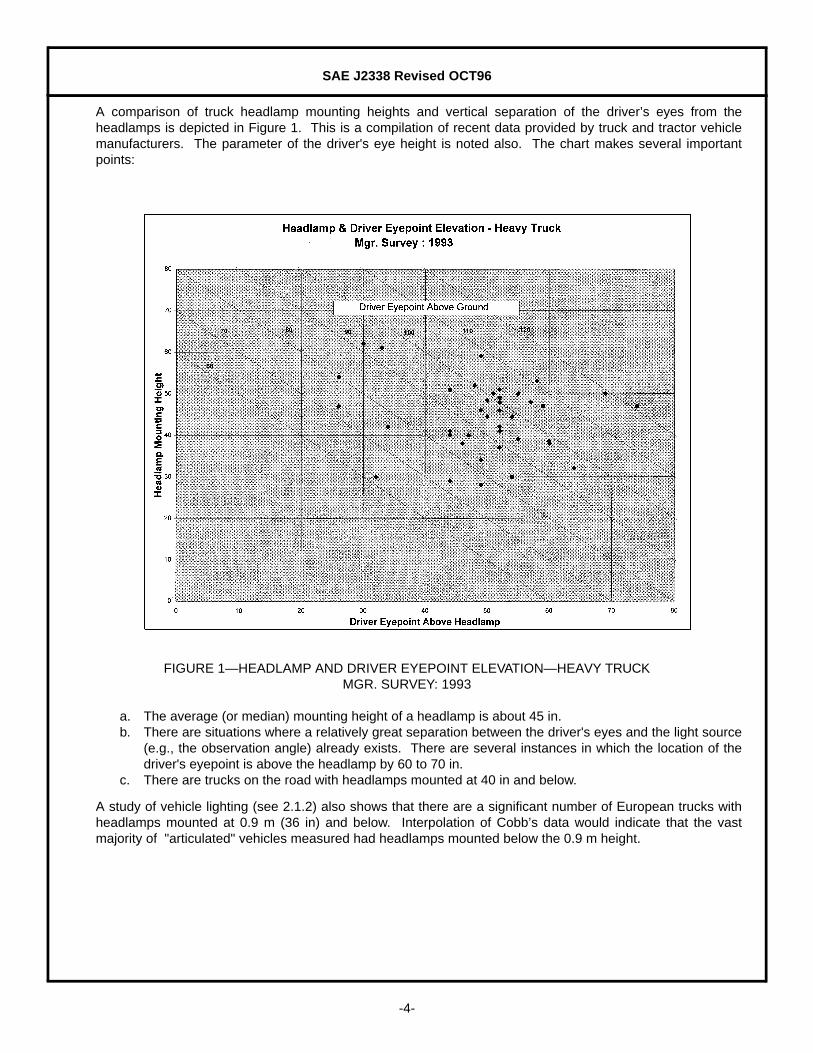
A comparison of truck headlamp mounting heights and vertical separation of the driver’s eyes from theheadlamps is depicted in Figure 1. This is a compilation of recent data provided by truck and tractor vehiclemanufacturers. The parameter of the driver's eye height is noted also. The chart makes several importantpoints:
FIGURE 1—HEADLAMP AND DRIVER EYEPOINT ELEVATION—HEAVY TRUCKMGR. SURVEY: 1993
a. The average (or median) mounting height of a headlamp is about 45 in.b. There are situations where a relatively great separation between the driver's eyes and the light source
(e.g., the observation angle) already exists. There are several instances in which the location of thedriver's eyepoint is above the headlamp by 60 to 70 in.
c. There are trucks on the road with headlamps mounted at 40 in and below.
A study of vehicle lighting (see 2.1.2) also shows that there are a significant number of European trucks withheadlamps mounted at 0.9 m (36 in) and below. Interpolation of Cobb’s data would indicate that the vastmajority of "articulated" vehicles measured had headlamps mounted below the 0.9 m height.
SAE J2338 Revised OCT96
-5-
Based on these data, and having no information that the vehicles noted above have caused drivers toexperience problems with large observation angles, the argument that a loss of sign legibility will have dramaticnegative safety effects does not appear to be substantiated. As will be explained in a later paragraph, driversviewing oncoming traffic from elevated positions actually experience a significant reduction in glare and areduction in the dark-adaptation effect resulting from this reduced glare.
5. Detection Distance Effect—The detection or discernibility distance for headlighting systems has beenstudied in real roadway situations and with mathematical algorithms over the years. In almost all cases thesestudies concentrated on passenger vehicles. In most of these cases mounting height was not the issue.
In the limited situations in which headlamp mounting location was studied, there was a detection distance lossnoted as a result of lowered mounting height of the vehicle headlamps. While numbers such as "10 ft loss per1-in mounting height reduction" are stated, this was for passenger vehicle headlamps which were alreadymounted relatively low; in the range of 25 in. The obstacles in some detection distance tests conducted byRoper or Meese, were 40 cm x 40 cm (16 in2) targets. The "targets" were generally detected at 200 to 250 ftdepending on the headlamp system. The "center" of the target (at 8 in above the roadway) is located 17 inbelow the center of the headlamp at a distance of 225 ft. At this point in the beam, it is illuminated by light atabout 0.36 degree below the top of the beam cutoff. This is in the area where the beam gradient is very large.A reduction of 2 in in mounting height implies that the location of the target center would now be located slightlyover 0.04 degree higher in the beam pattern. Beam gradients in this area are generally 25%, or even 35% per1/10 degree, and a change of one-half of 1/10 degree would imply that 12 to 16% less light illuminates theobstacle.
Application of the inverse distance law would dictate that if the headlamps are lowered 2 in, the detectiondistance should fall by approximately 6 to 8% of 225 ft or 14 to 18 ft. So for a 1-in mounting height change, aloss of 7 to 9 ft is implied. This analysis confirms (approximately) the generalization of "10 ft detection loss per1 in" mounting height reduction. This applies, in a general sense at least, to passenger vehicles. We will seein the following sections that the rule is not generally applicable to headlamps mounted at greater mountingheights in large truck types of vehicles.
5.1 Detection Distance With Lowered Mounting Height—It is possible to determine the effect of mountingheight differences by actual dynamic testing similar to that described above. However, this would be difficultand costly to do with actual trucks and tractors.
The implications of performing static testing using mock-ups of vehicle front ends, stationary targets, and"driver-observers" at varying heights has been discussed. Even this task was daunting for the amount andrelevance of the information which might be gained. There are some who feel that static obstacle detectiontests do not fairly depict actual roadway obstacle detection distances. Some of the reasons for this are theabsence of secondary tasks such as lane-keeping and speed maintenance, as well as longer (or artificial)target acquisition time intervals. For these reasons, the data acquired from static tests are always somewhatinsensitive to subtle light level differences. Longer, sometimes significantly longer, detection distances aretypical of static tests relative to distances found in dynamic tests.
5.2 Detection Distance Model—In the interest of defining the effect of lowered mounting height, without incurringthe expense and time penalty of dynamic road tests, a simpler modeling experiment was undertaken. Thedistance at which a roadway obstacle would be discerned by the driver of a motor vehicle is a function of theobstacle luminance and contrast with the background. For many roadway situations, the background is thedistant roadway surface and therefore it is at a significantly lower luminance than the illuminated obstacle. Thecontrast requirement is generally satisfied in this situation. At any rate over a short distance the contrast ratiocan be shown to be relatively invariant and we can infer that the detection distance becomes simply a functionof threshold luminance.
SAE J2338 Revised OCT96
-6-
A model (see 2.1.3) which compares the distance-related headlamp illumination with the distance-relatedillumination required for detection of the obstacle was used to predict the (relative) effect of reducing headlampheight from the average noted previously (45 in) to a reduced (36 in) height. The obstacle characteristicsselected for the calculations were: 3 ft2 in area, 1.5 ft high, 0.10 reflectance (.1 ft-lambert/Fc). The vehicleheadlamp spacing used was 60 inches. An H6054 (Type 2B1) lamp was chosen for the experiment because ofits widespread use in the industry and its known level of photometric performance.
In order to determine the illumination of the obstacle at various distances from the vehicle, the angular positionof the obstacle's center was calculated as a function of distance for each headlamp at the two mountingheights of interest. A representative GE H6054 headlamp was evaluated at each of these angulardisplacements. A programmable LMT G-1200 gonio-photometer was used to make the photometric readingswith the lamp aimed photometrically to its nominal fractional balance aim. The light falling on the obstaclecenter is the simple summation of the separate contributions of the right and left headlamps. Use of theinverse-square relationship then yields the obstacle illumination as a function of distance from the headlampsto the obstacle.
The detection requirements as a function of distance were calculated by the algorithms proposed by Kosmatka(see 2.1.4). This was done for each of two cases: one in which the driver is nonexpectant (i.e., not reasonablyanticipating a roadway obstacle), and one in which the driver is "expectant" and has reason to anticipate thatthere will be an obstacle in or near the path of the vehicle.
5.3 Detection Distance Model Results—Comparison of the illumination provided by the headlamp system andthe illumination required for detection or discernibility of the obstacle yielded the approximate distance at whichthe detection criterion is satisfied. This is shown in Table 1:
5.4 Discussion of Detection Distance Results—The detection distance loss predicted by the detection distancemodel contradicts conventional lore based on previous studies of the distance "lost" per inch of mountingheight reduction. There are several reasons for this. As discussed previously, the "10 ft/in rule" may take somelicense in rounding numbers that are somewhat less than "10 ft."
However, there is another, more profound reason that we find less of a reduction at severely elevated mountingheights. It is an artifact of the beam patterns made by halogen lamps. In general, halogen type lamps havesmaller, more compact coils than did their standard incandescent counterparts. The wire temperature is(generally) elevated, resulting in more lumens per watt. Also, as a general rule, the filament wire's diameter issmaller. This increases the resistance-per-unit-length and results in a shorter wire segment for a givenwattage and life rating. The coiled filament is smaller in length and diameter in halogen cycle headlamps.
TABLE 1—DETECTION DISTANCE
MOUTING HEIGHT EXPECTANT DRIVER NONEXPECTANT DRIVERat 45 in 264 ft (80 m) 157 ft (47.5 m)at 36 in 251 ft (76 m) 144 ft (43.6 m)
% change 5% 8%
SAE J2338 Revised OCT96
-7-
The combination of more lumens and smaller coiled tungsten filaments allows a "brighter" and more “luminous”source. This results in a smaller, more compact, and brighter projected beam pattern with more light a the topof the beam, compared to the relatively inferior non-halogen headlamps. The center of the high intensity zoneis closer to the top cutoff of the beam. The beam is more compact from top to bottom, with the center of"maximum beam intensity" (MBI) located closer to the top of the beam than the bottom, in the range of 1.5 to2 degrees below the horizontal. This was not the case in the older style of headlamps. In the standardincandescent designs, the MBI was located farther down from the top of the beam pattern, frequently at 2.5and even 3 degrees down. The gradient continued to increase and provide more light on obstacles locatedlower in the beam.
The gradients commonly found in modern halogen lamps have already had their most significant effect atlocations of zero to 1 degree down. Placing an obstacle lower in the beam pattern by elevating the lamp'smounting height has a diminished effect. A corollary statement might be that some lowering of the mountingheight will have a much smaller effect on the light falling on the obstacle than would have been the case forearlier headlamp designs. (It is worth noting that at some point, raising the mounting height will place theobject on the down-side of the gradient and there will actually be less light falling on the obstacle.)
6. Glare Reduction Considerations for Truck Vehicles—While most arguments point out the negative effectsof having the driver’s eyes at elevated heights, few recognize the counter-effecting advantages. High densitytraffic situations are the most critical for drivers for two reasons. First, there is a loss of visual acuity due toglare and elevated adaptation levels. Second, the traffic density may make alternative means of prolonging theobservation time more difficult. In this situation it is easy to argue that driver needs are most critical.
The driver of a large vehicle is located such that the eyepoint is at approximately eight feet above the road. Apassenger vehicle driver’s eye height is approximately 3.5 ft. For the sake of argument we’ll assume theoncoming vehicles’ headlamps are located at a two-foot elevation. The position of the drivers’ eyes in thebeams is described by Equation 1:
(Eq. 1)
where:
h is the eyepoint elevation with respect to the headlamp and d is the distance from the headlamp to theeyepoint.
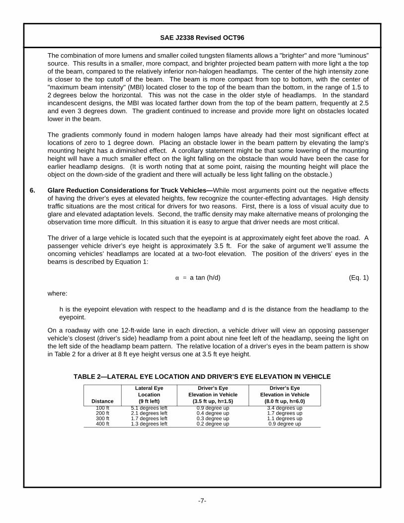
On a roadway with one 12-ft-wide lane in each direction, a vehicle driver will view an opposing passengervehicle’s closest (driver’s side) headlamp from a point about nine feet left of the headlamp, seeing the light onthe left side of the headlamp beam pattern. The relative location of a driver’s eyes in the beam pattern is showin Table 2 for a driver at 8 ft eye height versus one at 3.5 ft eye height.
TABLE 2—LATERAL EYE LOCATION AND DRIVER’S EYE ELEVATION IN VEHICLE
Distance
Lateral EyeLocation(9 ft left)
Driver’s EyeElevation in Vehicle
(3.5 ft up, h=1.5)
Driver’s EyeElevation in Vehicle
(8.0 ft up, h=6.0)100 ft 5.1 degrees left 0.9 degree up 3.4 degrees up200 ft 2.1 degrees left 0.4 degree up 1.7 degrees up300 ft 1.7 degrees left 0.3 degree up 1.1 degrees up400 ft 1.3 degrees left 0.2 degree up 0.9 degree up
α a tan (h/d)=
SAE J2338 Revised OCT96
-8-
Observation of a typical ISO-candela diagram for an automotive headlamp with an SAE beam pattern will showthat the glare light directed at the eyepoint above will be about one-half as much for the more elevated (8 ft)driver’s eyepoint than for the driver with his eyes at an elevation of only 3.5 ft. At a 200 ft distance, a passengercar driver would view about 800 cd from an oncoming headlamp. A driver at a height of 8 ft would be exposedto only 450 cd. At 300 ft we find similar results: about 1200 cd for a passenger car and around 600 cd for atruck driver. At 400 ft the respective levels are about 1500 cd and 800 cd.
Adaptation level (and the object luminance required) is approximately in proportion to the glare light differential;then it would follow that compared to a passenger car driver, a driver with an eyepoint at 8 ft will require onlyabout one-half as much luminance (as of a sign for instance). Drivers of truck vehicles, who would be moredisadvantaged by a reduction in headlamp mounting height, are also located in the beams of oncoming trafficin such a way that in the more demanding situation of “opposing traffic glare” they require less target luminancethan vehicle drivers who are located in the more intense portion of oncoming headlamp beams.
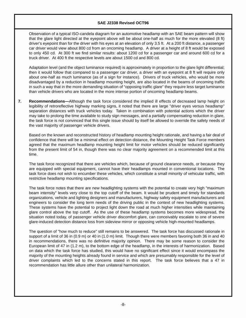
7. Recommendations—Although the task force considered the implied ill effects of decreased lamp height onlegibility of retroreflective highway marking signs, it noted that there are large "driver eyes versus headlamp"separation distances with truck vehicles today. Taken in combination with potential actions which the drivermay take to prolong the time available to study sign messages, and a partially compensating reduction in glare,the task force is not convinced that this single issue should by itself be allowed to override the safety needs ofthe vast majority of passenger vehicle drivers.
Based on the known and reconstructed history of headlamp mounting height rationale, and having a fair deal ofconfidence that there will be a minimal effect on detection distance, the Mounting Height Task Force membersagreed that the maximum headlamp mounting height limit for motor vehicles should be reduced significantlyfrom the present limit of 54 in, though there was no clear majority agreement on a recommended limit at thistime.
The task force recognized that there are vehicles which, because of ground clearance needs, or because theyare equipped with special equipment, cannot have their headlamps mounted in conventional locations. Thetask force does not wish to encumber these vehicles, which constitute a small minority of vehicular traffic, withrestrictive headlamp mounting specifications.
The task force notes that there are new headlighting systems with the potential to create very high ”maximumbeam intensity” levels very close to the top cutoff of the beam. It would be prudent and timely for standardsorganizations, vehicle and lighting designers and manufacturers, highway safety equipment manufacturers andengineers to consider the long term needs of the driving public in the context of new headlighting systems.These systems have the potential to project light down the road at much higher intensities while maintainingglare control above the top cutoff. As the use of these headlamp systems becomes more widespread, thesituation noted today, of passenger vehicle driver discomfort glare, can conceivably escalate to one of severeglare-induced detection distance loss from sideview mirror or opposing vehicle high-mounted headlamps.
The question of "how much to reduce" still remains to be answered. The task force has discussed rationale insupport of a limit of 36 in (0.9 m) or 40 in (1.0 m) limit. Though there were members favoring both 36 in and 40in recommendations, there was no definitive majority opinion. There may be some reason to consider theEuropean limit of 47 in (1.2 m), to the bottom edge of the headlamp, in the interests of harmonization. Basedon data which the task force has studied, this would have no significant effect since it would encompass themajority of the mounting heights already found in service and which are presumably responsible for the level ofdriver complaints which led to the concerns stated in this report. The task force believes that a 47 inrecommendation has little allure other than unilateral harmonization.
SAE J2338 Revised OCT96
-9-
A minority opinion expressed by engineers involved with retroreflective sign materials and performancesuggested that other “of the many components contributing to glare” should be studied along with the legibilityeffect of increased observation angles. They did not agree that a “significant reduction in mounting height” wasin the best interest of the road user but suggested that beam distribution, headlight output, glare limits andrearview mirror efficiency should all be studied. These factors do in some fashion all contribute to passengercar driver glare; however, this proposal does not address the dichotomous situation where truck vehicleheadlamps are simply located above the passenger vehicle driver’s eyepoint, or above the side view mirror.The light intensity levels here are ten or twenty times that in the “glare” portion of the pattern upon which theexisting standard was based. It is this same high intensity light upon which drivers depend to illuminate thedistant roadway.
It is the recommendation of the Mounting Height Task Force that the transportation industry and standardsassociations consider significantly reducing the limit of mounting height for headlamps on vehicles whose basicpurpose is transportation of people and goods over public roadways. The task force does not believe it isnecessary to apply a new definition of headlamp mounting height to specialized vehicles which requireheadlamps mounted above the normal range as dictated by the vehicle’s intended use (i.e., "construction"vehicles such as bulldozers, "special purpose" vehicles such as snow plows or vehicles whose only function isnonhighway use such as vehicles used for open or underground mining operations).
The task force recommendation is based on the information available and the belief that the marginal detectiondistance loss for some vehicles is offset by the greater good of reducing glare for the vast majority ofpassenger vehicle drivers. The task force understands that sign legibility is still a salient issue but hasconsidered the precedent of current practice on many contemporary truck vehicles.
PREPARED BY THE SAE MOUNTING HEIGHT TASK FORCE OF THELIGHTING COORDINATING COMMITTE
SAE J2338 Revised OCT96
Rationale—Not applicable.
Relationship of SAE Standard to ISO Standard—Not applicable.
Application—The Society of Automotive Engineers task force on headlamp mounting height has consideredthe ramifications of reducing the maximum mounting height of headlamps on highway vehicles. The taskforce has concluded that it is in the best interest of the driving public to make a significant reduction in therecommended maximum height at which headlamps, particularly lower beam headlamps, may bemounted. Heights as low as 36 to 40 in (0.9 to 1.0 m) have been considered. New tractor vehicles are infact being designed with headlamps mounted in this range. Further recommendations were withheld inanticipation of tests to demonstrate the effect of mounting height on the legibility of certain overheadsigns.
Reference Section
Sivak, M., Flannagan, M., Gellatly, A.W., “Influence of Truck Driver Eye Position on Effectiveness ofRetroreflective Traffic Signs,” Ltg. Res. Technology, 25(1) 31-36, (1993)
Cobb, J., “Roadside Survey of Vehicle Lighting 1989,” Transport and Road Research Laboratory, U.K.,Research Report 290, (1989)
Kosmatka, W.J., “Obstacle Detection with Headlamps: Threshold Luminance or Contrast,” Proceedingsof IES, IENSA Conference - 1995, (1995)
Kosmatka, W.J., “Obstacle Detection Rationale for Vehicle Headlamps,” J of the IES, Winter 1995, 36-40,(1994)
Developed by the SAE Mounting Height Task Force
Sponsored by the SAE Lighting Coordinating Committee