Embed Size (px)
Citation preview
Introduction
Vehicle Motion In Case Of Failure of Su-perposition Steering Systems Dipl.-Ing. Alexander Wesp Dipl.-Ing. Doris Schmidt Dr.-Ing. Norbert Fecher, Prof. Dr. rer. nat. Hermann Winner Technische Universität Darmstadt, Chair of Automotive Engineering
1. Introduction
For the investigation of the controllability of one superposition steering system the driver and vehicle reaction in the event of a failure were examined in the past.1 With an increasing spreading of active steering systems in further vehicles it is to be known necessarily the influ-ence of the changed vehicle parameters and actuator concepts on the controllability. This knowledge allows to transfer the results of the fail safe behavior on to other combinations of vehicles and actuator. For a broader investigation therefore four different vehicles were equipped with two different principles of superposition steering systems. The investigation was operated with the In-terdisziplinären Zentrum für Verkehrswissenschaften (IZVW) of Universität Würzburg and by the order of several vehicle manufacturers examined. In the context of this article the analysis of the vehicle reaction in the event of a failure is re-ported.
2. Actuator Concepts
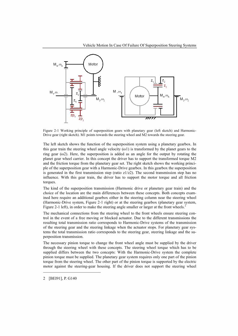
The distinctive feature of superposition steering systems is that they change the angle of the front wheels independent of the driver. So that the steering control of the vehicle remains even in the case of failure, both the concepts discussed here are equipped with mechanical connec-tions between the steering wheel and the front wheels. The additional steering angle is added with the help of a superposition transmission gearbox built into the steering system. This su-perposition transmission is build into the steering system between the steering gearbox (rack) and the steering wheel. Figure 2-1 shows the working principles of the two systems.
1 [NK03]
Vehicle Motion In Case Of Failure Of Superposition Steering Systems
Figure 2-1 Working principle of superposition gears with planetary gear (left sketch) and Harmonic-Drive gear (right sketch). M1 points towards the steering wheel and M2 towards the steering gear.
The left sketch shows the function of the superposition system using a planetary gearbox. In this gear train the steering wheel angle velocity (ω1) is transformed by the planet gears to the ring gear (ω2). Here, the superposition is added as an angle for the output by rotating the planet gear wheel carrier. In this concept the driver has to support the transformed torque M2 and the friction torque from the planetary gear set. The right sketch shows the working princi-ple of the superposition gear with a Harmonic-Drive gearbox. In this gearbox the superposition is generated in the first transmission step (ratio z1/z2). The second transmission step has no influence. With this gear train, the driver has to support the motor torque and all friction torques. The kind of the superposition transmission (Harmonic drive or planetary gear train) and the choice of the location are the main differences between these concepts. Both concepts exam-ined here require an additional gearbox either in the steering column near the steering wheel (Harmonic-Drive system, Figure 2-1 right) or at the steering gearbox (planetary gear system, Figure 2-1 left), in order to make the steering angle smaller or larger at the front wheels.2 The mechanical connections from the steering wheel to the front wheels ensure steering con-trol in the event of a free moving or blocked actuator. Due to the different transmissions the resulting total transmission ratio corresponds to Harmonic-Drive systems of the transmission of the steering gear and the steering linkage when the actuator stops. For planetary gear sys-tems the total transmission ratio corresponds to the steering gear, steering linkage and the su-perposition transmission. The necessary pinion torque to change the front wheel angle must be supplied by the driver through the steering wheel with these concepts. The steering wheel torque which has to be supplied differs between the two concepts: With the Harmonic-Drive system the complete pinion torque must be supplied. The planetary gear system requires only one part of the pinion torque from the steering wheel. The other part of the pinion torque is supported by the electric motor against the steering-gear housing. If the driver does not support the steering wheel 2 [BEI91], P. G140
torque only one part of the additional angle can be transformed into a change of the front wheel angles. Regarding the controllability in consequence of a failure, it should be noted that a reaction torque at the steering wheel is in the opposite direction of the torque applied by the electric motor at the pinion.
3. Investigation Method
For the investigation of the vehicle reaction in an event of an error of a superposition steering system, the pattern of a failure and the properties which causes the biggest disturbance on the vehicle motion has to be defined. A simple and plausible pattern represents a step-steer change of the front wheel angle, which corresponds to the pattern of a spontaneously starting actuator (“self steering”). This pattern can be divided onto its time history in malfunctions, which would be in time detected and taken back by control devices (“reversible” malfunctions) and malfunctions, which cannot be taken back (“non reversible” malfunctions). In the case of irre-versible malfunctions after the detection of the actuator is just switched off after detection. By stopping the actuator the system changes the transmission ratio to the mechanical base ratio, which is defined by the steering gear ratio and the passive superposition transmission ratio. Dependent on the steering wheel angle at the time the system is switched off, a remaining steering wheel offset occurs. The function of the whole system corresponds then to a conven-tional steering system. If a reversible malfunction is detected the error angle of the actuator can be reversed by the actuator turning back again. For the analysis of the vehicle reaction, irreversible malfunctions and reversible malfunctions were examined at different speeds on dry roads. The irreversible malfunctions are described by the time to set up the error amplitude, the error angle and the direction of the error. For a re-versible error the holding time and the time for the dismantling of the error amplitude is added to the description of the malfunction. The increasing amplitude of the error takes place with the maximum dynamic performance of the actuator in order to get the maximum disturbance in the vehicle motion. The time span of a reversible error varies from 50 ms to 200 ms. The measurements were done in a straight line at speeds of 50 km/h, 80 km/h, 100 km/h and 150 km/. To determine the influence of lateral acceleration on the vehicle motion the distur-bance is repeated in steady state cornering conditions by different lateral accelerations. To investigate the influence of the steering wheel torque on the vehicle reaction, tests with a blocked steering wheel (“fixed control”) and a free steering wheel (“free control”) were carried out. The locking of the steering wheel was done by an actuated clamping device wedged onto the steering wheel rim.
4. Data Recording and Data Processing
The necessary recording of the measuring signals was done completely by CAN. The longitu-dinal and lateral velocities were measured by an optical correlation sensor mounted on the rear of the vehicles. The steering angle of the left front wheel was determined by a mechanical measuring system, which measures the angles of the wheel relative to the vehicle body. The yaw rate and the lateral acceleration of the vehicle were measured by a common, external sen-
Vehicle Motion In Case Of Failure Of Superposition Steering Systems
sor cluster. The steering wheel angle and the pinion angle signals were generated by the origi-nal sensors of the superposition system and recorded via CAN. The steering wheel torque was measured by special measuring steering wheels or measuring steering columns. The recorded signals were filtered off line with a zero-phase digital filter. With the exception of the steering wheel torque all signals where filtered with a cutoff frequency of 5 Hz. The steering wheel torque was prepared with a cutoff frequency of 15 Hz. The maxima of the signals were deter-mined within an interval from the start of the error angle to 750 ms after starting the error angle, to ensure that only the disturbances of the vehicle motion as a consequence of the error angle were detected.
5. Experimental Vehicles
The following table (Table 1), which includes the basic data of the four experimental vehicles, shows the dynamic range which was covered by the four vehicles. These vehicles are represen-tative for a broad range of vehicles in the upper-middle passenger car segment and the sports car segment.
Table 1: Experimental vehicle properties
Vehicle 1 Vehicle 2 Vehicle 3 Vehicle 4 Mass 1900 kg 1834 kg 1820 kg 1526 kg Wheelbase 2.65 m 2.88 m 2.85 m 2.35 m Characteristic Velocity 21.4 m/s 27.5 m/s 24.9 m/s 23 m/s imech 14.5 13.5 16.3 14.6
Superposition Principle Harmonic-Drive Gear Planetary Gear Harmonic-Drive
Gear Planetary Gear
For classification of the test vehicles the characteristic velocity was determined in steady state cornering with a constant radius of 50 m on dry road. The characteristic velocity is based on the corrected steering wheel angle over the lateral acceleration. With the help of the character-istic acceleration and the double Ackermann angle, the characteristic velocity is determined. Vehicle 1 was equipped with all-wheel drive while the remaining vehicles where rear wheel drive.
6. Results
To ensure comparability between the vehicles, the overall steering ratio was corrected on the velocity-dependent part of the superposition steering system, so that the steering wheel angle is equal to the pinion angle of the steering-gear box. This correction is necessary so as to be in-dependent of the variable steering ratio of the superposition systems. Therefore the pinion angle has a comparable meaning to the steering wheel angle of vehicles without superposition steering systems. In this way, the determined characteristic velocity corresponds to the usual
definition, and so it is possible to compare these vehicles with vehicles without superposition steering systems. For the comparison of the test results of the four vehicles between themselves the motions are laid on over the nominal front wheel angle. The nominal front wheel angle is calculated from the error amplitude at the pinion with blocked steering wheel and the basic mechanical ratio from the steering gear and steering linkage (see equation 1). The influence of the nonlinearity of the steering linkage is small due to the examined error angles and can be neglected therefore in the further views. The nominal front wheel angle was used to compare all results.
pinionnom
mechiδ
δ = (1)
The transmission ratios mechi for the vehicles are given in table 1.
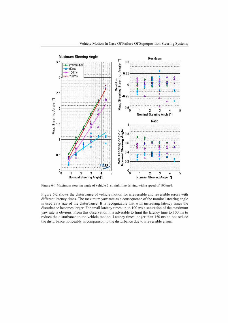
All of the following diagrams show the measurement results on the left. The upper right dia-gram shows the residual of the measurement data and the line of best fit. The residual gives a hint of the linearity of the measured data. The line of best fit is printed in the left diagram. The lower right diagram shows the ratio of the measured data. The linear relationship between x- and y-data appears as a constant line in this diagram. The maximum steering angle indicates the largest steering angle in the direction of the error. The indicated maximum steering angles were corrected by the offset angle, which was calcu-lated at the time of the error release on the wheel. Figure 6-1 shows irreversible errors and reversible errors with latencies from 50 ms to 200 ms for vehicle 2. In the case of reversible errors with small latencies (here 50 ms) it is recogniz-able that despite an increase of the error angle, no increase to the steering wheel angle takes place. This could be observed on all experimental vehicles. The reason for this is that the built-in actuators could not reach the given amplitude within the latency time. With larger latencies a larger wheel angle can be converted by the actuators in the available time. The transition of a reversible error with a latency of 200 ms in relation to an irreversible error shows only slightly larger steering angles concerning the maximum of measured steering angles. It can therefore be assumed that an almost complete conversion of the error to a wheel steering angle is reached with latency times over 200 ms.
Vehicle Motion In Case Of Failure Of Superposition Steering Systems
Figure 6-1 Maximum steering angle of vehicle 2, straight line driving with a speed of 100km/h
Figure 6-2 shows the disturbance of vehicle motion for irreversible and reversible errors with different latency times. The maximum yaw rate as a consequence of the nominal steering angle is used as a size of the disturbance. It is recognizable that with increasing latency times the disturbance becomes larger. For small latency times up to 100 ms a saturation of the maximum yaw rate is obvious. From this observation it is advisable to limit the latency time to 100 ms to reduce the disturbance to the vehicle motion. Latency times longer than 150 ms do not reduce the disturbance noticeably in comparison to the disturbance due to irreversible errors.
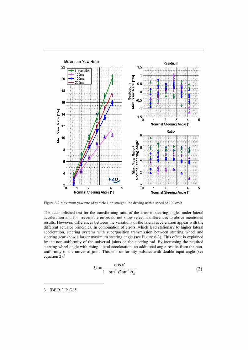
Figure 6-2 Maximum yaw rate of vehicle 1 on straight line driving with a speed of 100km/h
The accomplished test for the transforming ratio of the error in steering angles under lateral acceleration and for irreversible errors do not show relevant differences to above mentioned results. However, differences between the variations of the lateral acceleration appear with the different actuator principles. In combination of errors, which lead stationary to higher lateral acceleration, steering systems with superposition transmission between steering wheel and steering gear show a larger maximum steering angle (see Figure 6-3). This effect is explained by the non-uniformity of the universal joints on the steering rod. By increasing the required steering wheel angle with rising lateral acceleration, an additional angle results from the non-uniformity of the universal joint. This non uniformity pulsates with double input angle (see equation 2).3
2 2
cos1 sin sin H
U ββ δ
=−
(2)
3 [BEI91], P. G65
Vehicle Motion In Case Of Failure Of Superposition Steering Systems
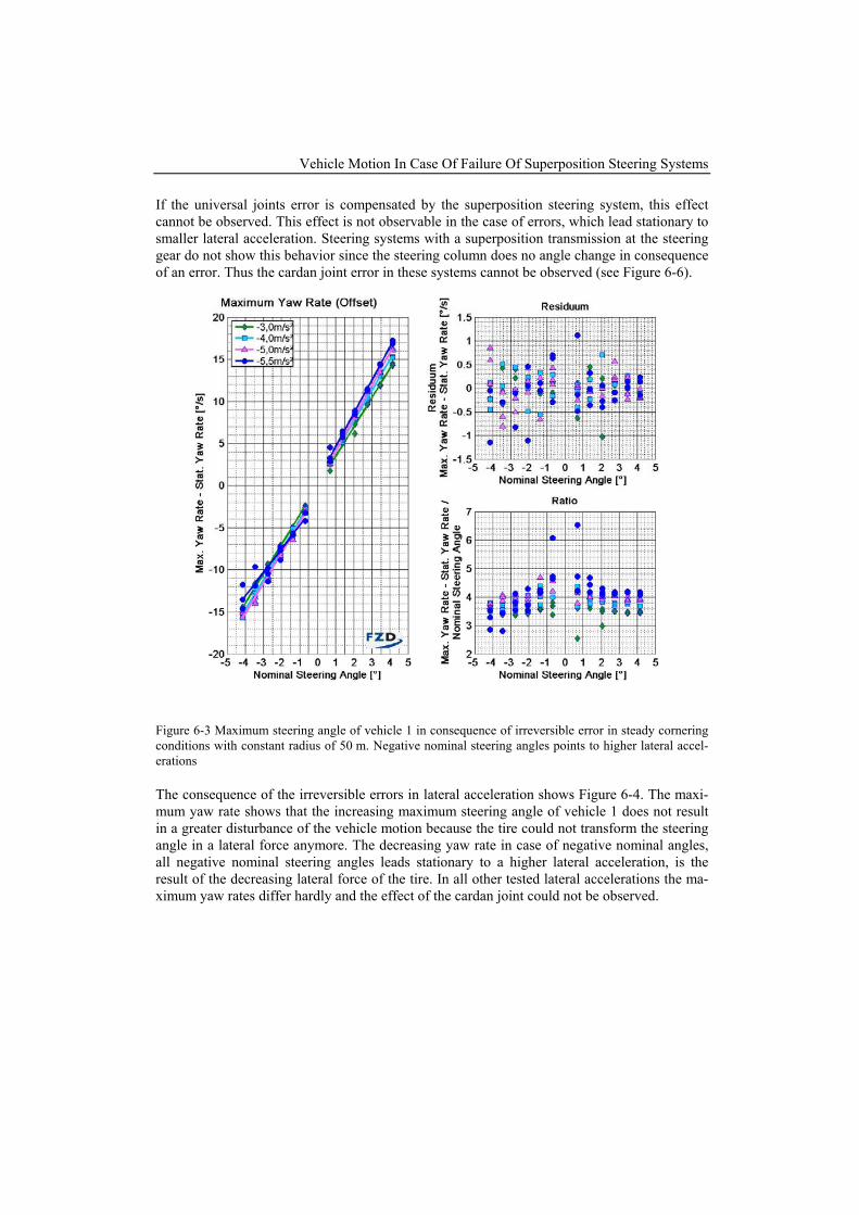
If the universal joints error is compensated by the superposition steering system, this effect cannot be observed. This effect is not observable in the case of errors, which lead stationary to smaller lateral acceleration. Steering systems with a superposition transmission at the steering gear do not show this behavior since the steering column does no angle change in consequence of an error. Thus the cardan joint error in these systems cannot be observed (see Figure 6-6).
Figure 6-3 Maximum steering angle of vehicle 1 in consequence of irreversible error in steady cornering conditions with constant radius of 50 m. Negative nominal steering angles points to higher lateral accel-erations
The consequence of the irreversible errors in lateral acceleration shows Figure 6-4. The maxi-mum yaw rate shows that the increasing maximum steering angle of vehicle 1 does not result in a greater disturbance of the vehicle motion because the tire could not transform the steering angle in a lateral force anymore. The decreasing yaw rate in case of negative nominal angles, all negative nominal steering angles leads stationary to a higher lateral acceleration, is the result of the decreasing lateral force of the tire. In all other tested lateral accelerations the ma-ximum yaw rates differ hardly and the effect of the cardan joint could not be observed.
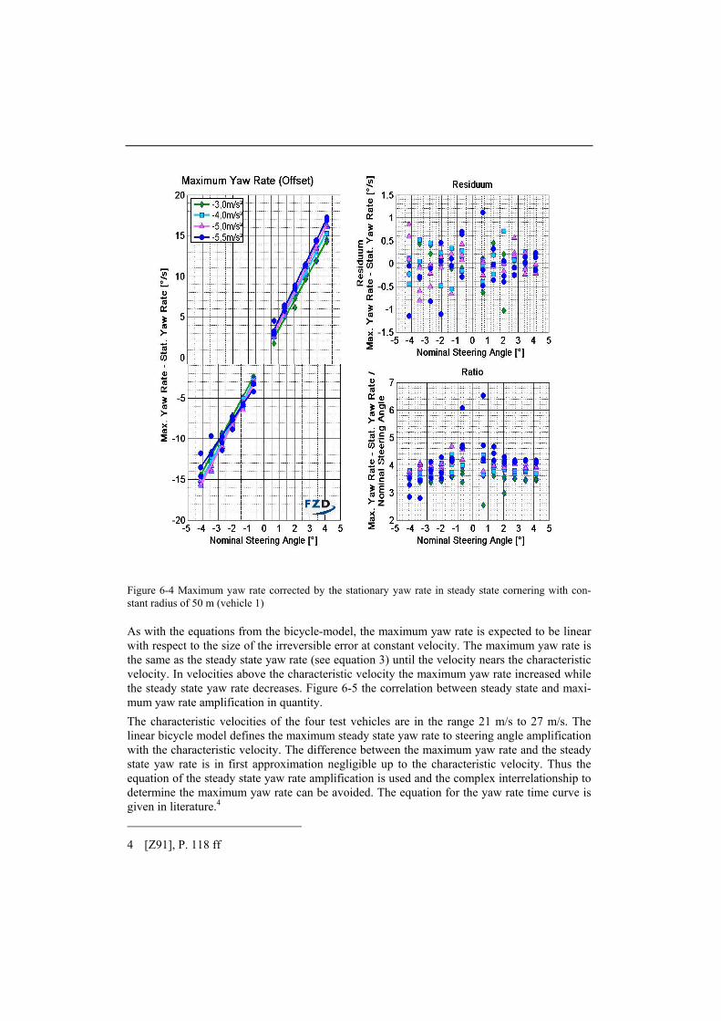
Figure 6-4 Maximum yaw rate corrected by the stationary yaw rate in steady state cornering with con-stant radius of 50 m (vehicle 1)
As with the equations from the bicycle-model, the maximum yaw rate is expected to be linear with respect to the size of the irreversible error at constant velocity. The maximum yaw rate is the same as the steady state yaw rate (see equation 3) until the velocity nears the characteristic velocity. In velocities above the characteristic velocity the maximum yaw rate increased while the steady state yaw rate decreases. Figure 6-5 the correlation between steady state and maxi-mum yaw rate amplification in quantity. The characteristic velocities of the four test vehicles are in the range 21 m/s to 27 m/s. The linear bicycle model defines the maximum steady state yaw rate to steering angle amplification with the characteristic velocity. The difference between the maximum yaw rate and the steady state yaw rate is in first approximation negligible up to the characteristic velocity. Thus the equation of the steady state yaw rate amplification is used and the complex interrelationship to determine the maximum yaw rate can be avoided. The equation for the yaw rate time curve is given in literature.4 4 [Z91], P. 118 ff
Vehicle Motion In Case Of Failure Of Superposition Steering Systems
The equation for the steady state yaw rate amplification is given in equation 3.
2 2(1 / )stat ges
char
i vl v v
ψδ
=+
(3)
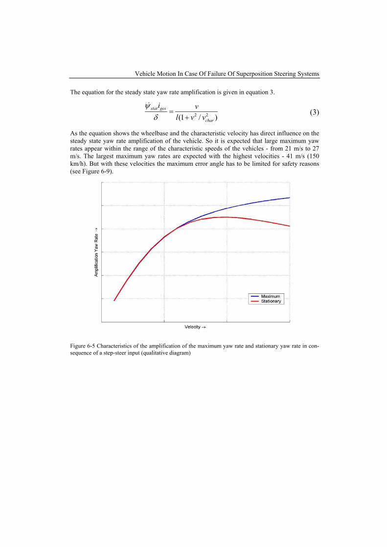
As the equation shows the wheelbase and the characteristic velocity has direct influence on the steady state yaw rate amplification of the vehicle. So it is expected that large maximum yaw rates appear within the range of the characteristic speeds of the vehicles - from 21 m/s to 27 m/s. The largest maximum yaw rates are expected with the highest velocities - 41 m/s (150 km/h). But with these velocities the maximum error angle has to be limited for safety reasons (see Figure 6-9).
Figure 6-5 Characteristics of the amplification of the maximum yaw rate and stationary yaw rate in con-sequence of a step-steer input (qualitative diagram)
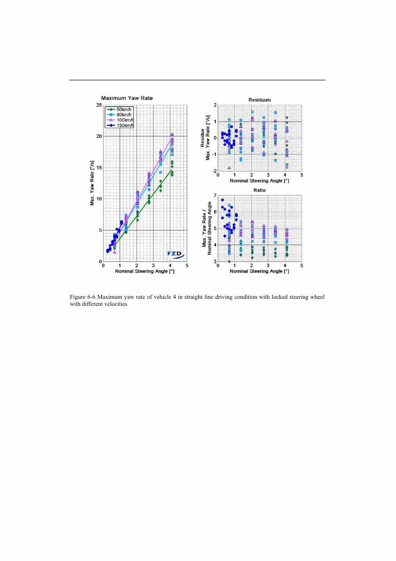
Figure 6-6 Maximum yaw rate of vehicle 4 in straight line driving condition with locked steering wheel with different velocities
Vehicle Motion In Case Of Failure Of Superposition Steering Systems
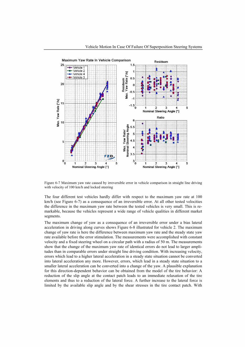
Figure 6-7 Maximum yaw rate caused by irreversible error in vehicle comparison in straight line driving with velocity of 100 km/h and locked steering
The four different test vehicles hardly differ with respect to the maximum yaw rate at 100 km/h (see Figure 6-7) as a consequence of an irreversible error. At all other tested velocities the difference in the maximum yaw rate between the tested vehicles is very small. This is re-markable, because the vehicles represent a wide range of vehicle qualities in different market segments. The maximum change of yaw as a consequence of an irreversible error under a bias lateral acceleration in driving along curves shows Figure 6-8 illustrated for vehicle 2. The maximum change of yaw rate is here the difference between maximum yaw rate and the steady state yaw rate available before the error stimulation. The measurements were accomplished with constant velocity and a fixed steering wheel on a circular path with a radius of 50 m. The measurements show that the change of the maximum yaw rate of identical errors do not lead to larger ampli-tudes than in comparable errors under straight line driving condition. With increasing velocity, errors which lead to a higher lateral acceleration in a steady state situation cannot be converted into lateral acceleration any more. However, errors, which lead in a steady state situation to a smaller lateral acceleration can be converted into a change of the yaw. A plausible explanation for this direction-dependent behavior can be obtained from the model of the tire behavior: A reduction of the slip angle at the contact patch leads to an immediate relaxation of the tire elements and thus to a reduction of the lateral force. A further increase to the lateral force is limited by the available slip angle and by the shear stresses in the tire contact patch. With
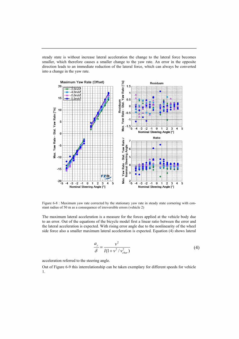
steady state is without increase lateral acceleration the change to the lateral force becomes smaller, which therefore causes a smaller change to the yaw rate. An error in the opposite direction leads to an immediate reduction of the lateral force, which can always be converted into a change in the yaw rate.
Figure 6-8 : Maximum yaw rate corrected by the stationary yaw rate in steady state cornering with con-stant radius of 50 m as a consequence of irreversible errors (vehicle 2)
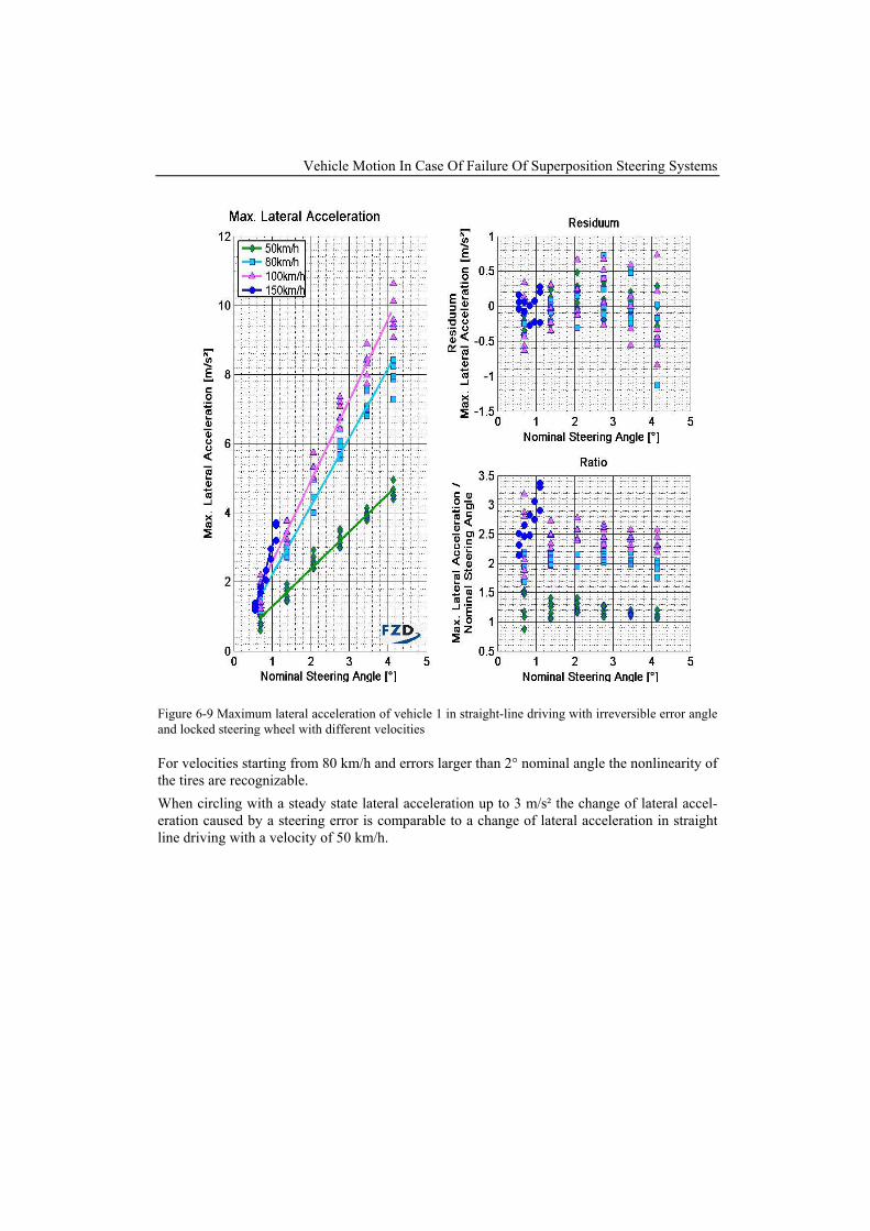
The maximum lateral acceleration is a measure for the forces applied at the vehicle body due to an error. Out of the equations of the bicycle model first a linear ratio between the error and the lateral acceleration is expected. With rising error angle due to the nonlinearity of the wheel side force also a smaller maximum lateral acceleration is expected. Equation (4) shows lateral
acceleration referred to the steering angle. Out of Figure 6-9 this interrelationship can be taken exemplary for different speeds for vehicle 1.
2
2 2(1 / )y
char
a vl v vδ
=+
(4)
Vehicle Motion In Case Of Failure Of Superposition Steering Systems
Figure 6-9 Maximum lateral acceleration of vehicle 1 in straight-line driving with irreversible error angle and locked steering wheel with different velocities
For velocities starting from 80 km/h and errors larger than 2° nominal angle the nonlinearity of the tires are recognizable. When circling with a steady state lateral acceleration up to 3 m/s² the change of lateral accel-eration caused by a steering error is comparable to a change of lateral acceleration in straight line driving with a velocity of 50 km/h.
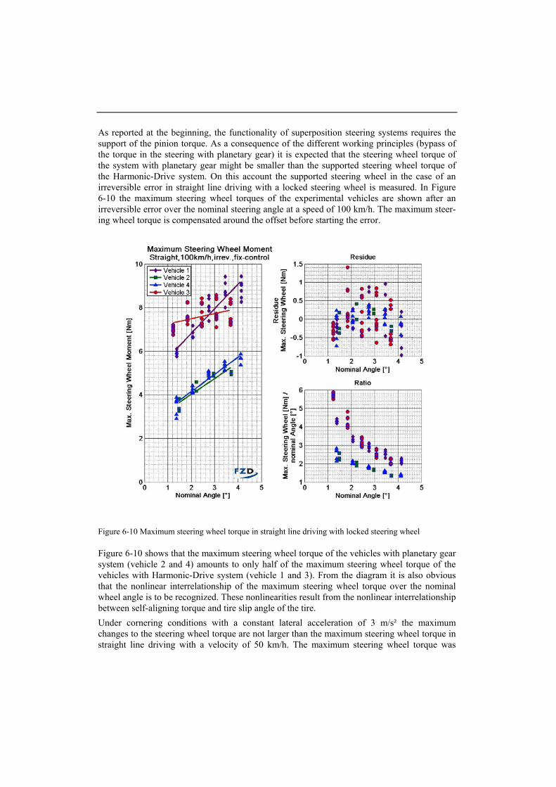
As reported at the beginning, the functionality of superposition steering systems requires the support of the pinion torque. As a consequence of the different working principles (bypass of the torque in the steering with planetary gear) it is expected that the steering wheel torque of the system with planetary gear might be smaller than the supported steering wheel torque of the Harmonic-Drive system. On this account the supported steering wheel in the case of an irreversible error in straight line driving with a locked steering wheel is measured. In Figure 6-10 the maximum steering wheel torques of the experimental vehicles are shown after an irreversible error over the nominal steering angle at a speed of 100 km/h. The maximum steer-ing wheel torque is compensated around the offset before starting the error.
Figure 6-10 Maximum steering wheel torque in straight line driving with locked steering wheel
Figure 6-10 shows that the maximum steering wheel torque of the vehicles with planetary gear system (vehicle 2 and 4) amounts to only half of the maximum steering wheel torque of the vehicles with Harmonic-Drive system (vehicle 1 and 3). From the diagram it is also obvious that the nonlinear interrelationship of the maximum steering wheel torque over the nominal wheel angle is to be recognized. These nonlinearities result from the nonlinear interrelationship between self-aligning torque and tire slip angle of the tire. Under cornering conditions with a constant lateral acceleration of 3 m/s² the maximum changes to the steering wheel torque are not larger than the maximum steering wheel torque in straight line driving with a velocity of 50 km/h. The maximum steering wheel torque was
Vehicle Motion In Case Of Failure Of Superposition Steering Systems
therefore corrected around the steady state part before applying the steering error. As well, in the straight line driving condition, the vehicles with the Harmonic-Drive system showed clearly higher maximum steering wheel torques than vehicles with the planetary gear system.
7. Conclusion
The investigation shows that reversible steering failures are less critical than irreversible steer-ing failures. The reason for this is that in the case of reversible steering errors, the time to in-fluence the vehicle motion is shorter than in case of irreversible steering errors, hence the dis-turbance of vehicle motion is smaller. The maximum steering angle in the case of a reversible error with latency time of 50 ms is limited to approximately 1 °. Reversible errors with latency of 200 ms hardly differ from the irreversible errors with respect to the maximum steering an-gle. The vehicle disturbance is in the case of reversible errors with latency of 200 ms smaller than those in the case of irreversible errors by maximum nominal steering angle. From this it is possibility to reduce the disturbance of the vehicle motion even if the exposure time to the steering error of up to 200 ms. Focusing maximum steering angle in consequence of an error a (velocity dependent) ratio between the maximum steering angle of the wheel and the nominal steering angle exist. This is also true for situations under lateral acceleration. Even in the case of uncorrected universal joint errors in steady state cornering conditions shows with increasing lateral acceleration a bigger maximum steering angle. But the influence on the disturbance of the vehicle motion is limited. In this situation the tire can not transform the slip angle into a lateral force. The tested vehicles represent a broad range of vehicle characteristics. The expected spread on vehicle disturbance as a consequence of a steering error could not be observed when the test-ing velocity was lesser than the characteristic velocity for the test vehicle. Overall the meas-ured disturbances to vehicle motion hardly differed within these ranges of velocities. The dis-turbances differ significantly when the velocity rising above the characteristic velocity. These results are valid for the maximum yaw rate as well as the maximum lateral acceleration. Dependent on the superposition steering concept used, different supporting torqueses were measured. Systems which use a Harmonic-Drive gear the drive have to support a higher steer-ing wheel torque compared to systems equipped with a planetary gearbox. An interpretation is difficult because the added torque of the electro motor is not known and the driver does not take the supported torque into account of subjective perception.
8. References
[BEI91] BEITZ, Wolfgang: Dubbel Taschenbuch für den Maschinenbau. Berlin u.a: 17., neu-bearb. Aufl. Aufl. Springer, 1991. - 3-540-52381-2 [EPK+02] ECKRICH, M. ; PISCHINGER, M. ; KRENN, M. ; BARTZ, R. ; MUNNIX, P.: Aktiv-lenkung - Anforderungen an Sicherheitstechnik und Entwicklungsprozess. In: Proc. of 11. Aachener Kolloquium Fahrzeug- und Motorentechnik, S. 1169-1184 (2002)
[DIN 70000] Deutsches Institut für Normung e.V., Berlin (1994) [NK03] NEUKUM, A. ; KRÜGER, H.-P.: Fahrerreaktionen bei Lenksystemstörungen - Unter-suchungsmethodik und Bewertungskriterien. In: VDI-Berichte, Nr. 1791, VDI-Verlag Düssel-dorf (2003) [Z91] ZOMOTOR, A.: Fahrwerktechnik: Fahrverhalten. Würzburg: Vogel Buchverlag, 1991