Embed Size (px)
Citation preview

High Reliability, Rack-Space Saving,Video and Audio Extension Solutions
T-4200 Modular Chassis KVM Extension Solution
Velocitykvm T-Series
Thinklogical LLC 100 Washington Street
Milford, Connecticut 06460 U.S.A.Telephone: 1-203-647-8700
Fax: 1-203-783-9949 www.thinklogical.com
Extend Distribute Innovate
®
PRODUCT MANUAL

®
T-4200 Chassis, Rev. A 2 September 2011
Extend Distribute Innovate
®
Copyright Notice Copyright © 2011. All rights reserved. Printed in the U.S.A. Thinklogical® LLC 100 Washington Street Milford, Connecticut 06460 U.S.A. Telephone: 1-203-647-8700 All trademarks and service marks are property of their respective owners.
Subject: VelocityKVM T-4200 Chassis Product Manual Revision: A, September, 2011
®
T-4200 Chassis, Rev. A 3 September 2011
Table of Contents PREFACE ...................................................................................................................................................... 4 Conventions Used in this Manual .............................................................................................................. 4 1. THE T-4200 MODULAR CHASSIS .......................................................................................................... 5 1.1 System Features ........................................................................................................................... 5 1.2 Technical Specifications .............................................................................................................. 6 1.3 Hardware ........................................................................................................................................ 6 1.3.1 Physical Connections ............................................................................................................ 6 1.3.2 Desktop or Rack Mount ......................................................................................................... 6 1.3.3 Cooling ..................................................................................................................................... 7 1.3.4 Hot Swappable Power Supplies ........................................................................................... 7 1.3.5 Display Rocker Switch ........................................................................................................... 8 1.3.6 Front Panel Display and Buttons .......................................................................................... 8 2. FIRMWARE UPGRADES ......................................................................................................................... 8
3. FRONT PANEL USAGE ........................................................................................................................... 9 3.1 Initial Power-Up ............................................................................................................................. 9 3.2 Saving Changes ..........................................................................................................................13 3.3 Restoring Factory Defaults ........................................................................................................14 3.4 Naming the Transmitter Unit .....................................................................................................15 4. REGULATORY & SAFETY COMPLIANCE ...........................................................................................16 4.1 Safety Requirements ..................................................................................................................16 4.1.1 Symbols Found on the Product .........................................................................................17 4.1.2 Regulatory Compliance .......................................................................................................17 North America ..........................................................................................................................17 Australia & New Zealand ........................................................................................................17 European Union ......................................................................................................................17 Declaration of Conformity ..................................................................................................17 4.1.3 Standards with Which the Products Comply ....................................................................17 4.2 Supplementary Information .......................................................................................................18 4.2.1 Product Serial Number ........................................................................................................19 4.2.2 Connection to the Product ..................................................................................................19 5. HOW TO CONTACT US .........................................................................................................................19 5.1 Customer Support ......................................................................................................................19 Website ........................................................................................................................................19 Email ............................................................................................................................................20 Telephone ....................................................................................................................................20 Fax ................................................................................................................................................20 5.2 Product Support ..........................................................................................................................20 5.2.1 Warranty ...............................................................................................................................20 5.2.2 Return Authorization ...........................................................................................................21 Our Address ..........................................................................................................................21
APPENDIX A: VelocityKVM T-Series Ordering Information ..................................................................22 APPENDIX B: Thinklogical KVM Extenders- Theory of Operation .......................................................23
®
T-4200 Chassis, Rev. A 4 September 2011
PREFACE Conventions Used in this Manual As you read this manual you will notice certain conventions that bring your attention to important information. These are Notes and Warnings. Examples are shown below.
Note: Important Notes appear in blue text preceded by a yellow exclamation point symbol, like this.
A note is meant to call the reader‟s attention to helpful information at a point in the text that is relevant to the subject being discussed.
Warning! All Warnings appear in red text, followed by blue text, and preceded by a red stop sign, like this.
A warning is meant to call the reader‟s attention to critical information at a point in the text that is relevant to the subject being discussed.
BEFORE STARTING ANY PROCEDURE, IT IS RECOMMENDED THAT YOU READ THE INSTRUCTIONS THOROUGHLY!
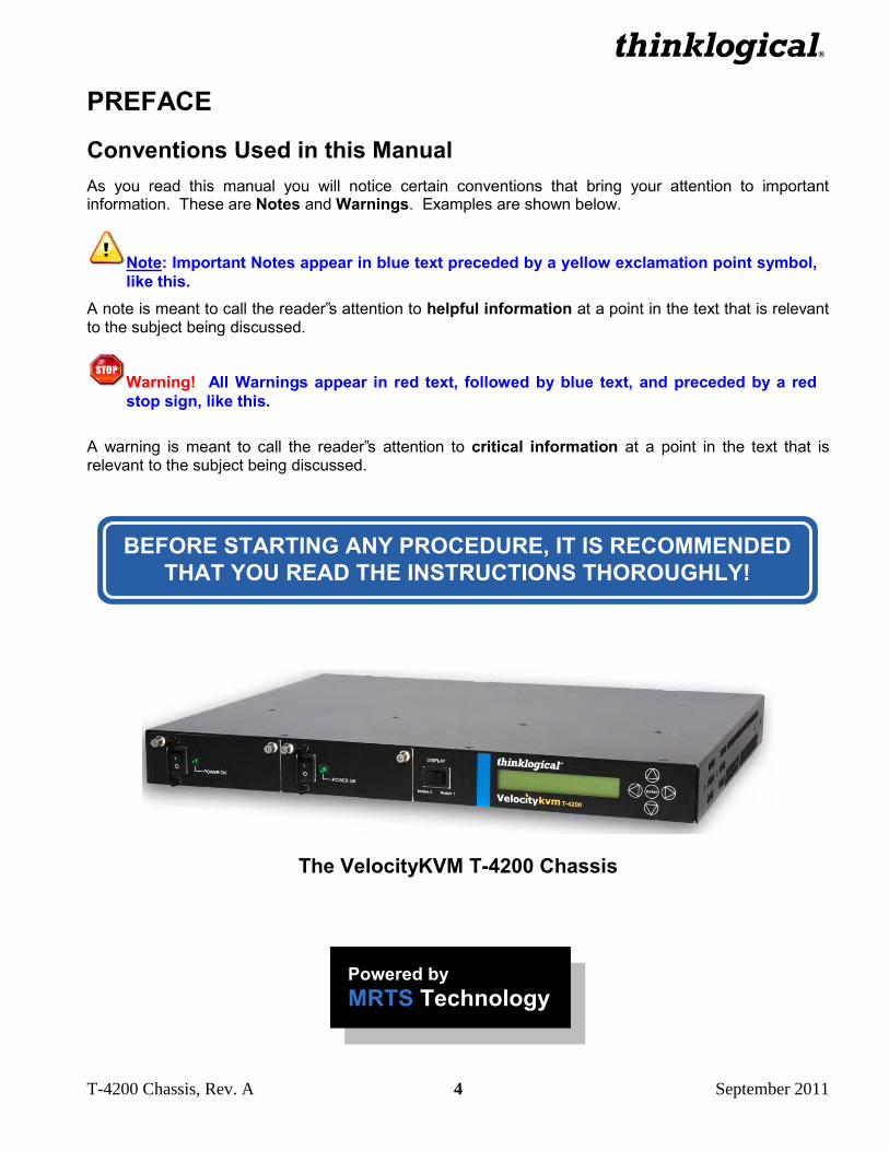
The VelocityKVM T-4200 Chassis
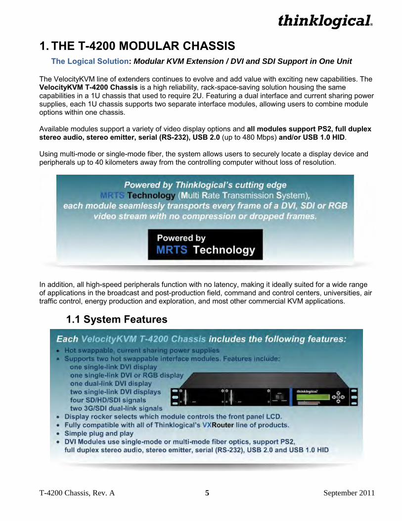
Powered byMRTS Technology
®
T-4200 Chassis, Rev. A 5 September 2011
1. THE T-4200 MODULAR CHASSIS The Logical Solution: Modular KVM Extension / DVI and SDI Support in One Unit
The VelocityKVM line of extenders continues to evolve and add value with exciting new capabilities. The VelocityKVM T-4200 Chassis is a high reliability, rack-space-saving solution housing the same capabilities in a 1U chassis that used to require 2U. Featuring a dual interface and current sharing power supplies, each 1U chassis supports two separate interface modules, allowing users to combine module options within one chassis. Available modules support a variety of video display options and all modules support PS2, full duplex stereo audio, stereo emitter, serial (RS-232), USB 2.0 (up to 480 Mbps) and/or USB 1.0 HID. Using multi-mode or single-mode fiber, the system allows users to securely locate a display device and peripherals up to 40 kilometers away from the controlling computer without loss of resolution.
In addition, all high-speed peripherals function with no latency, making it ideally suited for a wide range of applications in the broadcast and post-production field, command and control centers, universities, air traffic control, energy production and exploration, and most other commercial KVM applications.
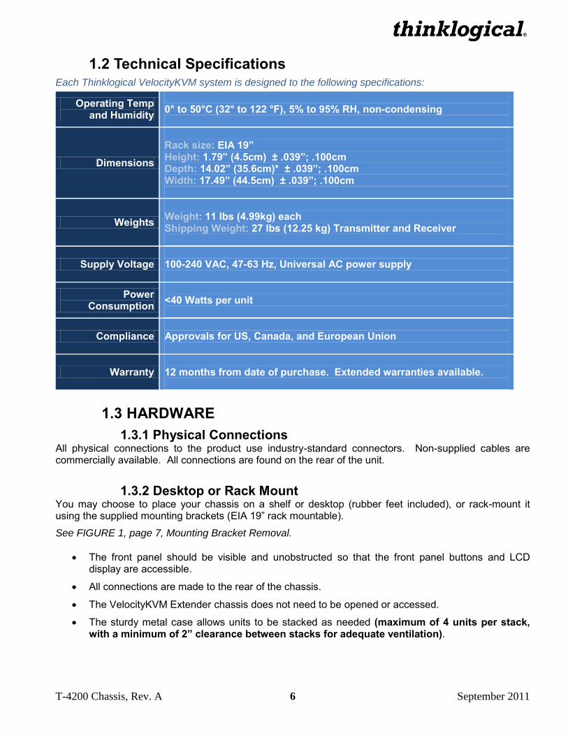
1.1 System Features
®
T-4200 Chassis, Rev. A 6 September 2011
1.2 Technical Specifications Each Thinklogical VelocityKVM system is designed to the following specifications:
Operating Temp and Humidity
0° to 50°C (32° to 122 °F), 5% to 95% RH, non-condensing
Dimensions
Rack size: EIA 19” Height: 1.79” (4.5cm) ± .039”; .100cm Depth: 14.02” (35.6cm)* ± .039”; .100cm Width: 17.49” (44.5cm) ± .039”; .100cm
Weights Weight: 11 lbs (4.99kg) each Shipping Weight: 27 lbs (12.25 kg) Transmitter and Receiver
Supply Voltage 100-240 VAC, 47-63 Hz, Universal AC power supply
Power Consumption
<40 Watts per unit
Compliance Approvals for US, Canada, and European Union
Warranty 12 months from date of purchase. Extended warranties available.
1.3 HARDWARE 1.3.1 Physical Connections
All physical connections to the product use industry-standard connectors. Non-supplied cables are commercially available. All connections are found on the rear of the unit.
1.3.2 Desktop or Rack Mount You may choose to place your chassis on a shelf or desktop (rubber feet included), or rack-mount it using the supplied mounting brackets (EIA 19” rack mountable).
See FIGURE 1, page 7, Mounting Bracket Removal.
The front panel should be visible and unobstructed so that the front panel buttons and LCD display are accessible.
All connections are made to the rear of the chassis.
The VelocityKVM Extender chassis does not need to be opened or accessed.
The sturdy metal case allows units to be stacked as needed (maximum of 4 units per stack, with a minimum of 2” clearance between stacks for adequate ventilation).
®
T-4200 Chassis, Rev. A 7 September 2011
8 Mounting bracket screws
DVI TWO DISPLAY
Velocitykvm-28
Fiber Optic Transmitter
2 Mounting bracket screws in four places.
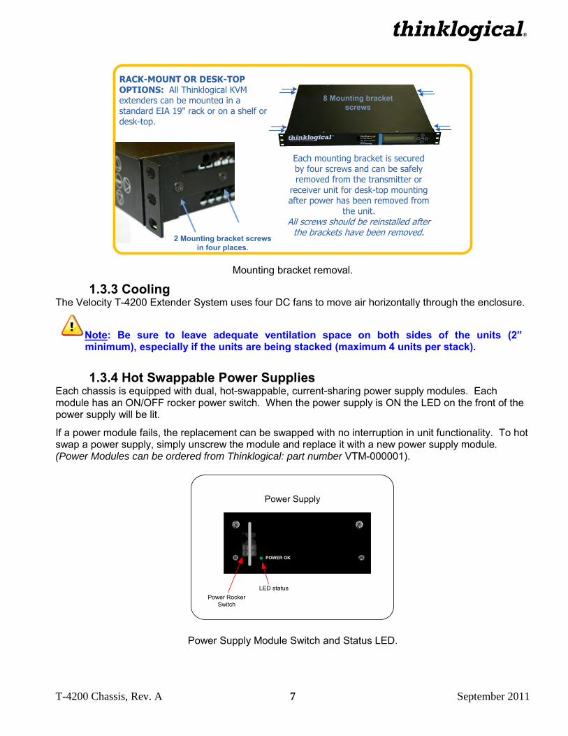
RACK-MOUNT OR DESK-TOP OPTIONS: All Thinklogical KVM extenders can be mounted in a standard EIA 19" rack or on a shelf or desk-top.
Each mounting bracket is secured by four screws and can be safely removed from the transmitter or
receiver unit for desk-top mounting after power has been removed from
the unit.All screws should be reinstalled after
the brackets have been removed.
Mounting bracket removal.
1.3.3 Cooling The Velocity T-4200 Extender System uses four DC fans to move air horizontally through the enclosure.
Note: Be sure to leave adequate ventilation space on both sides of the units (2” minimum), especially if the units are being stacked (maximum 4 units per stack).
1.3.4 Hot Swappable Power Supplies Each chassis is equipped with dual, hot-swappable, current-sharing power supply modules. Each module has an ON/OFF rocker power switch. When the power supply is ON the LED on the front of the power supply will be lit.
If a power module fails, the replacement can be swapped with no interruption in unit functionality. To hot swap a power supply, simply unscrew the module and replace it with a new power supply module. (Power Modules can be ordered from Thinklogical: part number VTM-000001).
POWER OK
Power Supply
Power Rocker Switch
LED status
Power Supply Module Switch and Status LED.
®
T-4200 Chassis, Rev. A 8 September 2011
1.3.5 Display Rocker Switch The Display rocker switch located on the front of the chassis selects which module information is shown on the LCD. Switched to the right or left, it will show the information for the module located on that side of the chassis. If there is only one module installed, it will display that module‟s information in either rocker switch position.
1.3.6 Front Panel Display and Buttons
Note: When you receive your T-4200 Chassis, there will be a removable decal that identifies each module of your specific configuration located on the front panel display.
The front-panel LCD display should be visible and accessible for system setup. The front panel buttons are used to configure special video settings and to review existing VelocityKVM Extender configurations. See Paragraph 3, Front Panel Usage below, for more information on using the buttons and LCD.
enter
POWER POWER Velocitykvm T- 4200Four Single-Link DVI Displays
DISPLAY
MODULE 2 MODULE 1
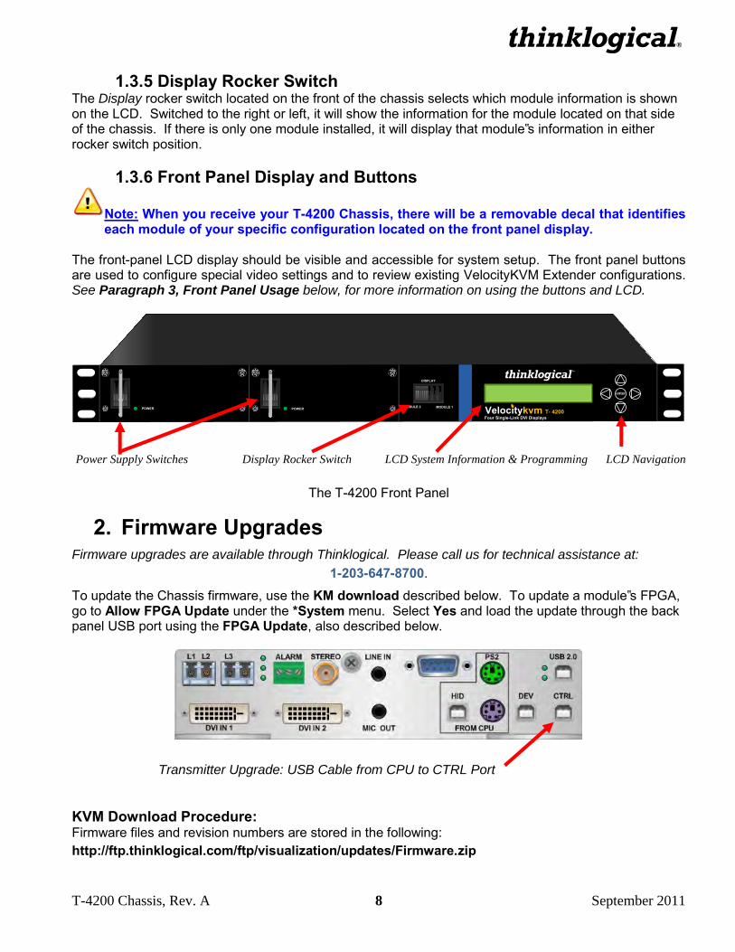
Power Supply Switches Display Rocker Switch LCD System Information & Programming LCD Navigation
The T-4200 Front Panel
2. Firmware Upgrades Firmware upgrades are available through Thinklogical. Please call us for technical assistance at:
1-203-647-8700.
To update the Chassis firmware, use the KM download described below. To update a module‟s FPGA, go to Allow FPGA Update under the *System menu. Select Yes and load the update through the back panel USB port using the FPGA Update, also described below.
Transmitter Upgrade: USB Cable from CPU to CTRL Port
KVM Download Procedure: Firmware files and revision numbers are stored in the following: http://ftp.thinklogical.com/ftp/visualization/updates/Firmware.zip
®
T-4200 Chassis, Rev. A 9 September 2011
The KM_Download.exe application and instructions are stored in: http://ftp.thinklogical.com/ftp/visualization/updates/KmDownloadVxxx.zip (where „Vxxx‟ is the version number). Firmware Update Preparation:
1. Retrieve the Firmware files/revision numbers and the KM_Download application/instructions and place them in an accessible directory in your CPU.
2. Install the KmDownload application (in KMDownloadVxxx.zip file) by running setup.exe. 3. Unzip the Firmware.zip file and place the contents in an accessible directory in your CPU.
4. Have a copy of the instructions and latest versions available for comparison after the update is complete.
FPGA Download Procedure: Firmware files and revision numbers are stored in the following: http://ftp.thinklogical.com/ftp/visualization/updates/FPGA.Firmware.zip The FPGA_Download.exe application & instructions are stored in: http://ftp.thinklogical.com/ftp/visualization/updates/FPGA_Upgrade.zip
FPGA Update Preparation: 1. Retrieve the Firmware files/revision numbers and the FPGA_Download application
/instructions and place them in an accessible directory in your CPU. 2. Copy the file FPGA_firmware.zip to a local directory and extract to a desired location. 3. Copy the file FPGA_upgrade.zip to a local directory. 4. Install setup.exe in FPGA_upgrade.zip.
5. Have a copy of the instructions and latest versions available for comparison after the update is complete.
3. Front Panel Usage 3.1 Initial Power-Up
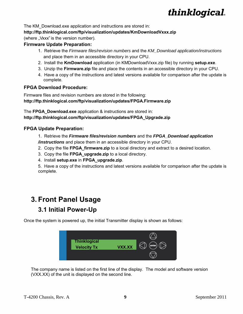
Once the system is powered up, the initial Transmitter display is shown as follows:
The company name is listed on the first line of the display. The model and software version (VXX.XX) of the unit is displayed on the second line.
Thinklogical Velocity Tx VXX.XX
®
T-4200 Chassis, Rev. A 10 September 2011
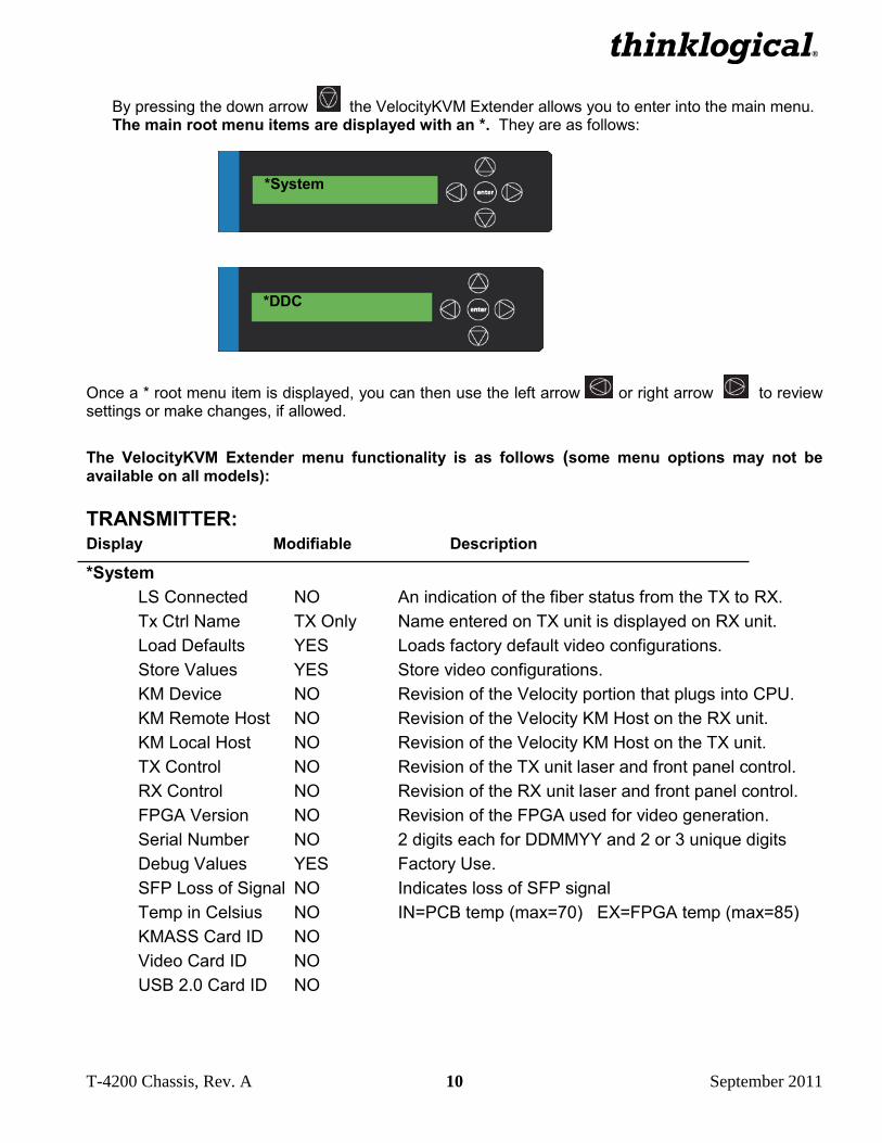
By pressing the down arrow the VelocityKVM Extender allows you to enter into the main menu. The main root menu items are displayed with an *. They are as follows:
Once a * root menu item is displayed, you can then use the left arrow or right arrow to review settings or make changes, if allowed. The VelocityKVM Extender menu functionality is as follows (some menu options may not be available on all models):
TRANSMITTER: Display Modifiable Description
*System LS Connected NO An indication of the fiber status from the TX to RX.
Tx Ctrl Name TX Only Name entered on TX unit is displayed on RX unit. Load Defaults YES Loads factory default video configurations. Store Values YES Store video configurations. KM Device NO Revision of the Velocity portion that plugs into CPU. KM Remote Host NO Revision of the Velocity KM Host on the RX unit. KM Local Host NO Revision of the Velocity KM Host on the TX unit. TX Control NO Revision of the TX unit laser and front panel control. RX Control NO Revision of the RX unit laser and front panel control. FPGA Version NO Revision of the FPGA used for video generation. Serial Number NO 2 digits each for DDMMYY and 2 or 3 unique digits Debug Values YES Factory Use. SFP Loss of Signal NO Indicates loss of SFP signal Temp in Celsius NO IN=PCB temp (max=70) EX=FPGA temp (max=85) KMASS Card ID NO Video Card ID NO USB 2.0 Card ID NO
*System
*DDC
®
T-4200 Chassis, Rev. A 11 September 2011
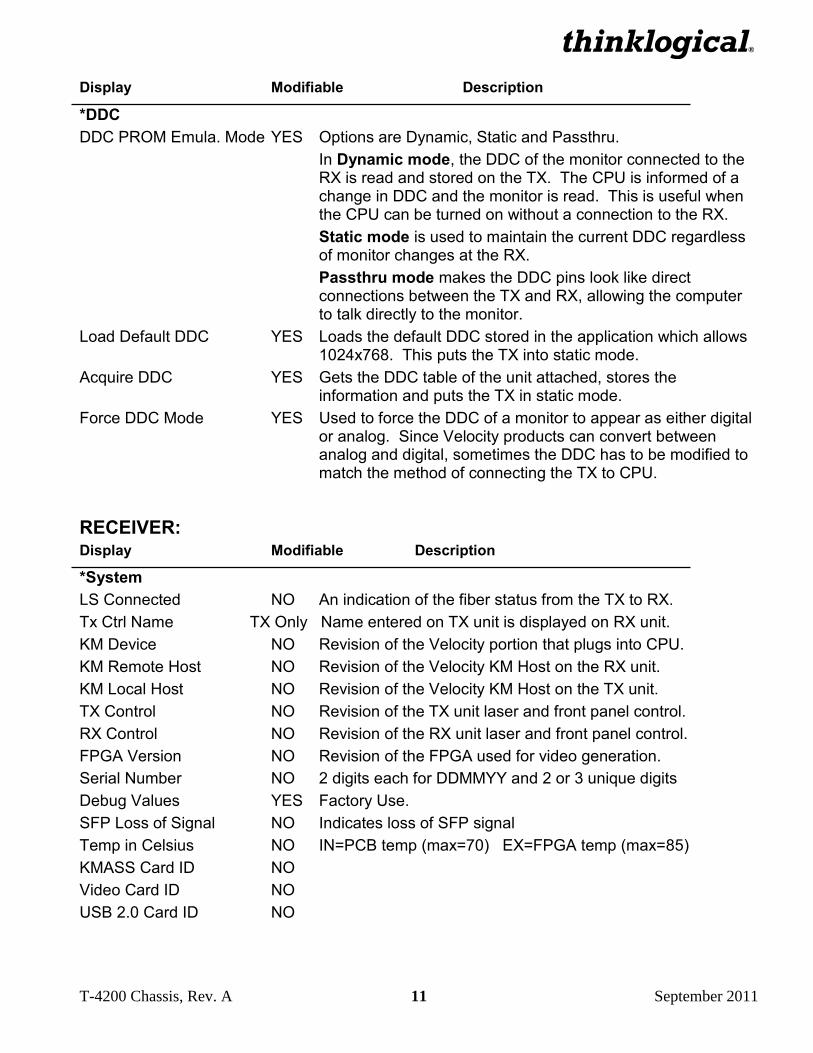
Display Modifiable Description
*DDC DDC PROM Emula. Mode YES Options are Dynamic, Static and Passthru. In Dynamic mode, the DDC of the monitor connected to the
RX is read and stored on the TX. The CPU is informed of a change in DDC and the monitor is read. This is useful when the CPU can be turned on without a connection to the RX.
Static mode is used to maintain the current DDC regardless of monitor changes at the RX.
Passthru mode makes the DDC pins look like direct connections between the TX and RX, allowing the computer to talk directly to the monitor.
Load Default DDC YES Loads the default DDC stored in the application which allows 1024x768. This puts the TX into static mode.
Acquire DDC YES Gets the DDC table of the unit attached, stores the information and puts the TX in static mode.
Force DDC Mode YES Used to force the DDC of a monitor to appear as either digital or analog. Since Velocity products can convert between analog and digital, sometimes the DDC has to be modified to match the method of connecting the TX to CPU.
RECEIVER: Display Modifiable Description
*System LS Connected NO An indication of the fiber status from the TX to RX. Tx Ctrl Name TX Only Name entered on TX unit is displayed on RX unit. KM Device NO Revision of the Velocity portion that plugs into CPU. KM Remote Host NO Revision of the Velocity KM Host on the RX unit. KM Local Host NO Revision of the Velocity KM Host on the TX unit. TX Control NO Revision of the TX unit laser and front panel control. RX Control NO Revision of the RX unit laser and front panel control. FPGA Version NO Revision of the FPGA used for video generation. Serial Number NO 2 digits each for DDMMYY and 2 or 3 unique digits Debug Values YES Factory Use. SFP Loss of Signal NO Indicates loss of SFP signal Temp in Celsius NO IN=PCB temp (max=70) EX=FPGA temp (max=85) KMASS Card ID NO Video Card ID NO USB 2.0 Card ID NO
®
T-4200 Chassis, Rev. A 12 September 2011
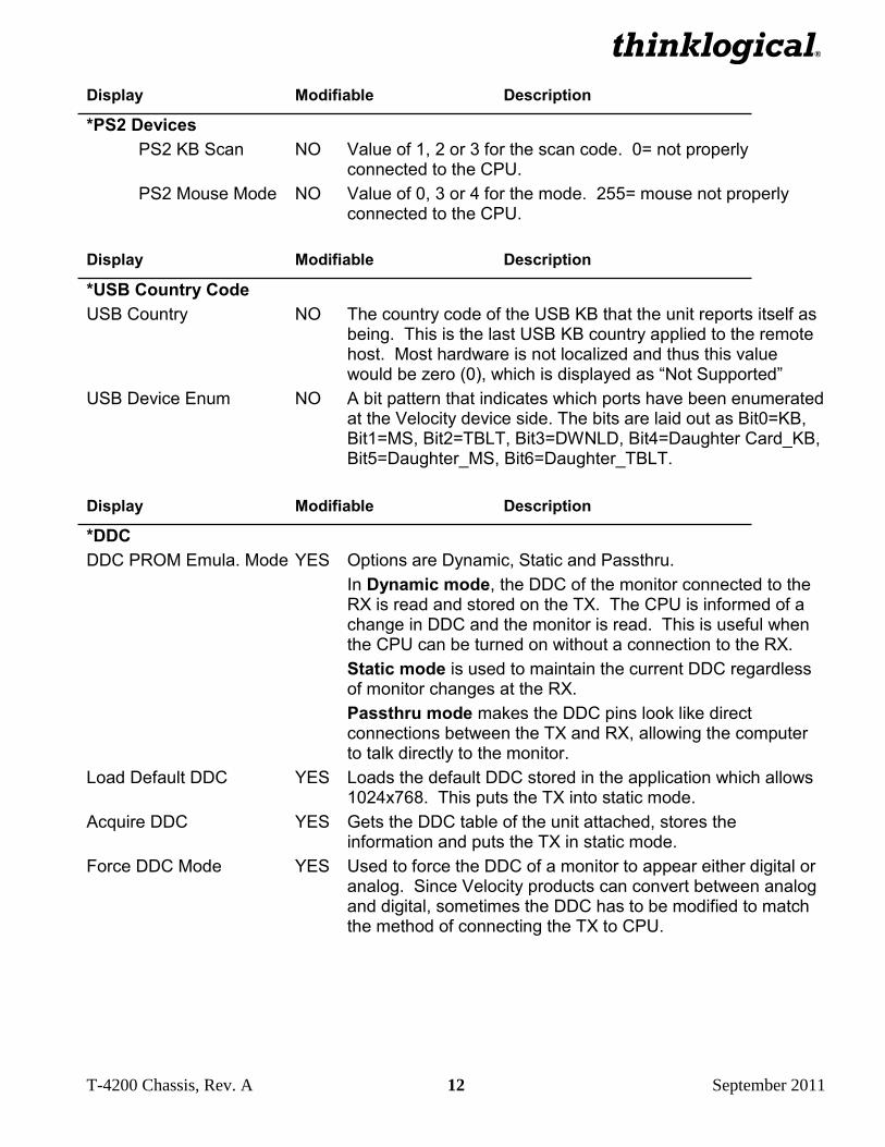
Display Modifiable Description
*PS2 Devices PS2 KB Scan NO Value of 1, 2 or 3 for the scan code. 0= not properly
connected to the CPU. PS2 Mouse Mode NO Value of 0, 3 or 4 for the mode. 255= mouse not properly
connected to the CPU. Display Modifiable Description
*USB Country Code USB Country NO The country code of the USB KB that the unit reports itself as
being. This is the last USB KB country applied to the remote host. Most hardware is not localized and thus this value would be zero (0), which is displayed as “Not Supported”
USB Device Enum NO A bit pattern that indicates which ports have been enumerated at the Velocity device side. The bits are laid out as Bit0=KB, Bit1=MS, Bit2=TBLT, Bit3=DWNLD, Bit4=Daughter Card_KB, Bit5=Daughter_MS, Bit6=Daughter_TBLT.
Display Modifiable Description
*DDC DDC PROM Emula. Mode YES Options are Dynamic, Static and Passthru. In Dynamic mode, the DDC of the monitor connected to the
RX is read and stored on the TX. The CPU is informed of a change in DDC and the monitor is read. This is useful when the CPU can be turned on without a connection to the RX.
Static mode is used to maintain the current DDC regardless of monitor changes at the RX.
Passthru mode makes the DDC pins look like direct connections between the TX and RX, allowing the computer to talk directly to the monitor.
Load Default DDC YES Loads the default DDC stored in the application which allows 1024x768. This puts the TX into static mode.
Acquire DDC YES Gets the DDC table of the unit attached, stores the information and puts the TX in static mode.
Force DDC Mode YES Used to force the DDC of a monitor to appear either digital or analog. Since Velocity products can convert between analog and digital, sometimes the DDC has to be modified to match the method of connecting the TX to CPU.
®
T-4200 Chassis, Rev. A 13 September 2011
Display Modifiable Description
*Video Video Tx 1 cnt. NO Video IN 1 pixel sample clock (TX) Video Rx 1 cnt. NO Video IN 1 pixel sample clock (RX) Video Tx 2 cnt. NO Video IN 2 pixel sample clock (TX) Video Rx 2 cnt. NO Video IN 2 pixel sample clock (RX) TX 1 Stream Info NO Video Channel 1 ID TX 2 Stream Info NO Video Channel 2 ID PropConst YES Factory default setting for debug IntegConst YES Factory default setting for debug
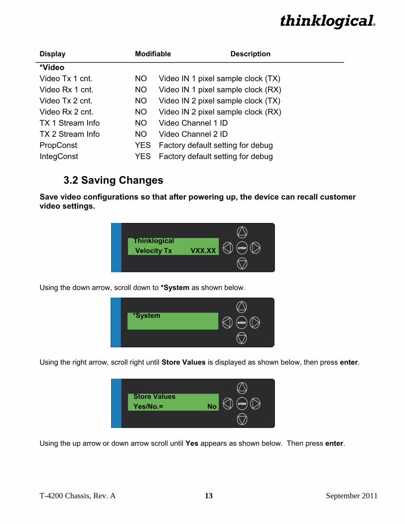
3.2 Saving Changes
Save video configurations so that after powering up, the device can recall customer video settings.
Using the down arrow, scroll down to *System as shown below.
Using the right arrow, scroll right until Store Values is displayed as shown below, then press enter.
Using the up arrow or down arrow scroll until Yes appears as shown below. Then press enter.
*System
Thinklogical Velocity Tx VXX.XX
Store Values Yes/No.= No
®
T-4200 Chassis, Rev. A 14 September 2011
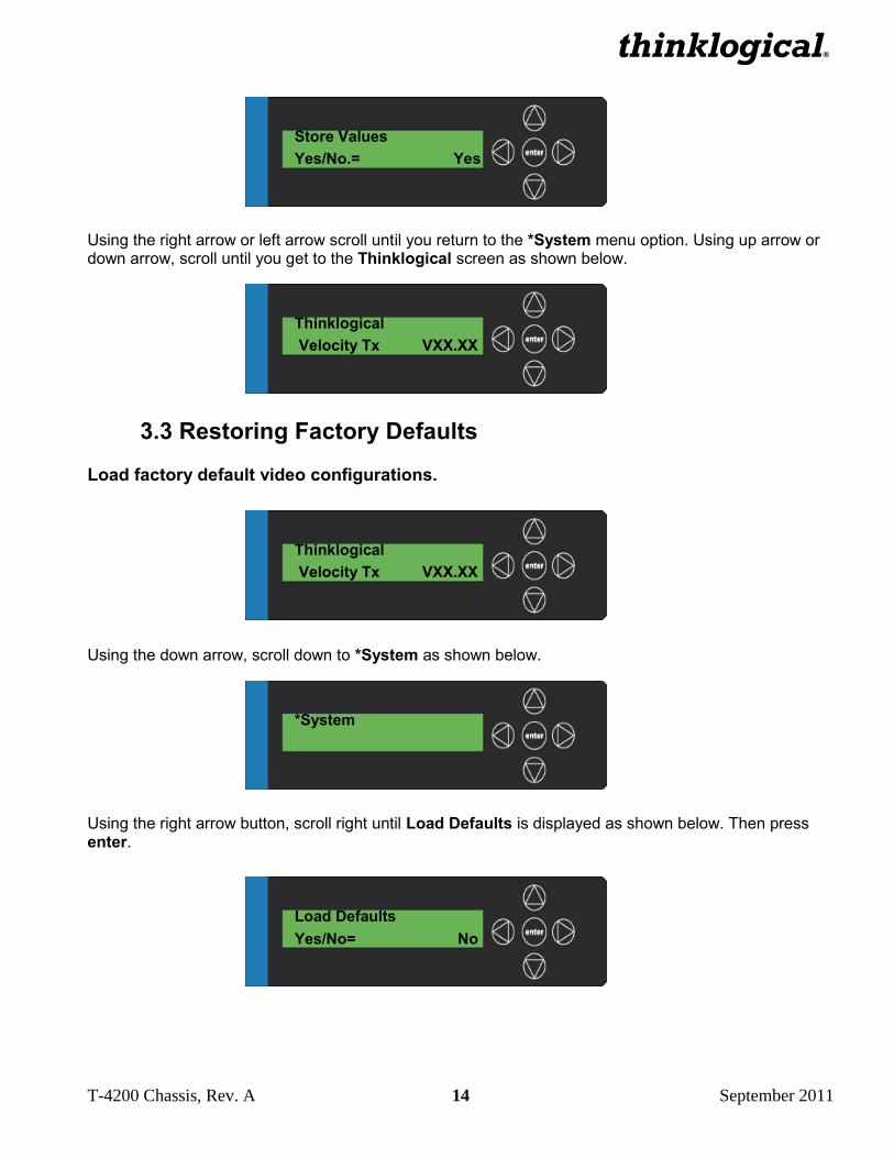
Using the right arrow or left arrow scroll until you return to the *System menu option. Using up arrow or down arrow, scroll until you get to the Thinklogical screen as shown below.
3.3 Restoring Factory Defaults
Load factory default video configurations.
Using the down arrow, scroll down to *System as shown below.
Using the right arrow button, scroll right until Load Defaults is displayed as shown below. Then press enter.
Thinklogical Velocity Tx VXX.XX
Store Values Yes/No.= Yes
Thinklogical Velocity Tx VXX.XX
*System
Load Defaults Yes/No= No
®
T-4200 Chassis, Rev. A 15 September 2011
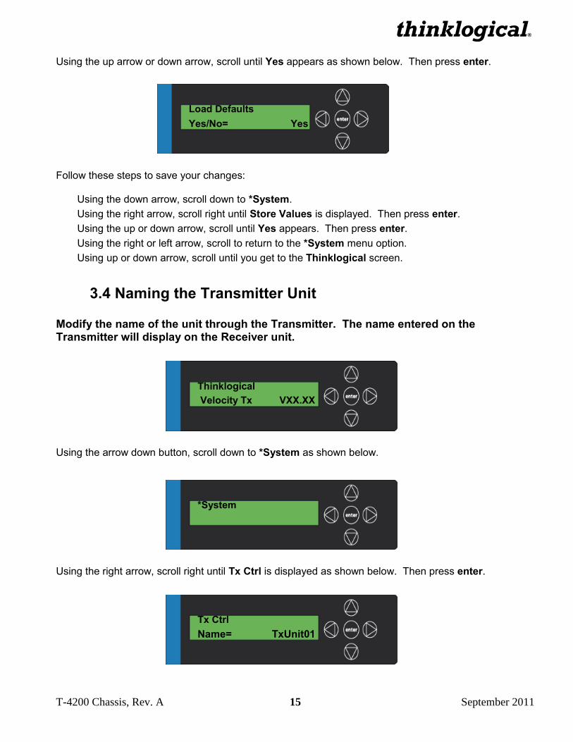
Using the up arrow or down arrow, scroll until Yes appears as shown below. Then press enter.
Follow these steps to save your changes:
Using the down arrow, scroll down to *System. Using the right arrow, scroll right until Store Values is displayed. Then press enter. Using the up or down arrow, scroll until Yes appears. Then press enter. Using the right or left arrow, scroll to return to the *System menu option. Using up or down arrow, scroll until you get to the Thinklogical screen.
3.4 Naming the Transmitter Unit
Modify the name of the unit through the Transmitter. The name entered on the Transmitter will display on the Receiver unit.
Using the arrow down button, scroll down to *System as shown below.
Using the right arrow, scroll right until Tx Ctrl is displayed as shown below. Then press enter.
Thinklogical Velocity Tx VXX.XX
Load Defaults Yes/No= Yes
*System
Tx Ctrl Name= TxUnit01
®
T-4200 Chassis, Rev. A 16 September 2011
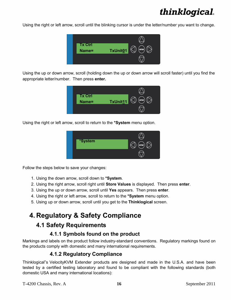
Using the right or left arrow, scroll until the blinking cursor is under the letter/number you want to change.
Using the up or down arrow, scroll (holding down the up or down arrow will scroll faster) until you find the appropriate letter/number. Then press enter.
Using the right or left arrow, scroll to return to the *System menu option.
Follow the steps below to save your changes:
1. Using the down arrow, scroll down to *System. 2. Using the right arrow, scroll right until Store Values is displayed. Then press enter. 3. Using the up or down arrow, scroll until Yes appears. Then press enter. 4. Using the right or left arrow, scroll to return to the *System menu option. 5. Using up or down arrow, scroll until you get to the Thinklogical screen.
4. Regulatory & Safety Compliance 4.1 Safety Requirements
4.1.1 Symbols found on the product Markings and labels on the product follow industry-standard conventions. Regulatory markings found on the products comply with domestic and many international requirements.
4.1.2 Regulatory Compliance Thinklogical‟s VelocityKVM Extender products are designed and made in the U.S.A. and have been tested by a certified testing laboratory and found to be compliant with the following standards (both domestic USA and many international locations):
Tx Ctrl Name= TxUnit01
*System
Tx Ctrl Name= TxUnit11
®
T-4200 Chassis, Rev. A 17 September 2011
All T-4200 modules are designed and identified as Class 1 LASER products.
CLASS 1 LASERS do not require any special
precautions under conditions of normal use.
North America
Safety ANSI/UL60950-1: 1st Edition (2003) CAN/CSA C22.2 No. 60950-1-03
LASER Safety CDRH 21CFR 1040.10 Class 1 LASER Product Electromagnetic Interference FCC CFR47, Part 15, Class A Industry Canada ICES-003 Issue 2, Revision 1
Australia & New Zealand This is a Class A product. In a domestic environment this product may cause radio interference, in which case the user may be required to take adequate measures.
European Union Declaration of Conformity Manufacturer‟s Name & Address: Thinklogical LLC
100 Washington Street Milford, Connecticut 06460 USA Telephone 1-203-647-8700
These products comply with the requirements of the Low Voltage Directive 72/23/EEC and the EMC Directive 89/336/EEC.
4.1.3 Standards with Which Our Products Comply Safety
CENELEC EN 60950-1, 1st Edition (2001)
LASER Safety IEC60825:2001 Parts 1 and 2 Class 1 LASER Product Electromagnetic Emissions EN55022: 1994 (IEC/CSPIR22: 1993) EN61000-3-2/A14: 2000 EN61000-3-3: 1994
®
T-4200 Chassis, Rev. A 18 September 2011
Electromagnetic Immunity EN55024: 1998 Information Technology Equipment-Immunity Characteristics EN61000-4-2: 1995 Electro-Static Discharge Test EN61000-4-3: 1996 Radiated Immunity Field Test EN61000-4-4: 1995 Electrical Fast Transient Test EN61000-4-5: 1995 Power Supply Surge Test EN61000-4-6: 1996 Conducted Immunity Test EN61000-4-8: 1993 Magnetic Field Test EN61000-4-11: 1994 Voltage Dips & Interrupts Test
4.2 Supplementary Information The following statements may be appropriate for certain geographical regions and might not apply to your location.
This Class A digital apparatus meets all requirements of the Canadian Interference-Causing Equipment Regulations.
Cet appareil numérique de la classe A respecte toutes les exigencies du Règlement sur le matérial
brouilleur du Canada.
Warning! This is a Class A product. In a domestic environment, this product may cause radio interference, in which case the user may be required to take corrective measures.
Note: This equipment has been tested and found to comply with the limits for a Class A digital device, pursuant to part 15 of the FCC Rules. These limits are designed to provide reasonable protection against harmful interference when the equipment is operated in a commercial environment. This equipment generates, uses and can radiate radio frequency energy and, if not installed and used in accordance with the instruction manual, may cause harmful interference to radio communications in which case the user may be required to take adequate corrective measures at their own expense.
Note: This Class A digital apparatus complies with Canadian ICES-003 and has been verified as being compliant within the Class A limits of the FCC Radio Frequency Device Rules (FCC Title 47, Part 15, Subpart B CLASS A), measured to CISPR 22: 1993 limits and methods of measurement of Radio Disturbance Characteristics of Information Technology Equipment.
Note: The user may notice degraded audio performance in the presence of electromagnetic fields.

®
T-4200 Chassis, Rev. A 19 September 2011
Note: If using a keyboard that is noise susceptible, a ferrite ring on the keyboard cable may be needed to comply with Immunity Requirements
4.2.1 Product Serial Number The T-4200 has a unique serial number printed on an adhesive label that is fixed to the bottom of the chassis. The serial number includes a date-code. The format for the date-code is 2 digits for the month, 2 digits for the day and 2 digits for the year, plus two or three digits for a unique unit number. This serial number is also found on the original shipping carton.
4.2.2 Connection to the Product Connections and installation hardware for our products use industry-standard devices and methods. All wiring connections to the customer equipment are designed to minimize proprietary or customized connectors and cabling. Power connections are made with regionally appropriate power cords and approved methods.
5. How to Contact Us 5.1 Customer Support
Thank you for choosing Thinklogical® products for your application.We appreciate your business and are dedicated to helping you successfully use our products.
is always here to help you.To contact us, please use the following telephone numbers and internet-based methods:
®
Thinklogical is an engineering company and you will receive the information you require directly from our most knowledgeable engineers. We believe that the first lines of support are the design engineers that developed the product. Therefore, your questions will be handled promptly by our in-house engineers who are most familiar with your products.
To contact Thinklogical, use the following telephone numbers and internet-based methods:
Website Visit our website for specific product information, current updates and our complete line of products at www.thinklogical.com.
Our internet website offers product information on all current systems, including technical specification sheets and installation guides (for viewing online or for download), product diagrams showing physical connections and other helpful information.
Note: Most online documents are stored as Adobe Acrobat “PDF” files. If you do not have the Adobe Acrobat reader needed to view PDF files, visit www.adobe.com for a download.

®
T-4200 Chassis, Rev. A 20 September 2011
Email Thinklogical is staffed Monday through Friday from 8:30am to 5:00pm, Eastern Time Zone. We will make every effort to respond to your email inquiries promptly. Please use the following email addresses for any of your concerns:
[email protected] – Information on Thinklogical and our products.
[email protected] – Sales Department - orders, questions or issues.
[email protected] – Product support, technical issues or questions, product repairs and request for Return Authorization.
Telephone Telephone Sales: Contact our expert sales staff via telephone in Milford, CT at 1-203-647-8700 or if in the continental USA, you may use our toll-free number 1-800-291-3211. We are here Monday through Friday from 8:30am to 5:00pm, Eastern Time Zone. Ask for your representative‟s direct dial phone number when you call. Telephone Product Support: Contact Product Support via telephone in Milford, CT at 1-203-647-8700. The support lines are manned Monday through Friday, 8:30am to 5:00pm, Eastern Time Zone. International Sales: Please contact our US sales staff in Milford, CT at 1-203-647-8700. We are here Monday through Friday, 8:30am to 5:00pm, Eastern Time Zone (same as New York City). If leaving a voice message please let us know when we can reach you at your convenience. Our switchboard attendant will direct your call during regular business hours. We have an automated attendant answering our main telephone switchboard after regular business hours and holidays. You can leave voice messages for individuals at any time. Our Sales Representatives have direct numbers for prompt service.
Fax Our company facsimile number is 1-203-783-9949. Please indicate the nature of the fax on your cover sheet and provide return contact information.
5.2 Product Support Thinklogical‟s support personnel are available Monday through Friday from 8:30am to 5:00pm, Eastern Time Zone. If your application requires assistance at some time outside of our normal business hours, please contact us beforehand and we will do our best to make arrangements to help you with your Thinklogical products.
5.2.1 Warranty Thinklogical warrants this product against defects in materials and workmanship for a period of one year from the date of delivery. Thinklogical and its suppliers disclaim any and all other warranties.
Note: Thinklogical LLC products carry a one year warranty with longer term available at time of purchase on most products. Please refer to your product invoice for your product’s Warranty Terms & Conditions.
®
T-4200 Chassis, Rev. A 21 September 2011
Defect remedy shall be the repair or replacement of the product, provided that the defective product is returned to the authorized dealer within a year from the date of delivery. If you wish to return your device, contact the Thinklogical authorized dealer where you purchased the device, or if you purchased directly, call Thinklogical at 1-800-291-3211 (USA).
5.2.2 Return Authorization In the event you must return a product to Thinklogical directly:
Contact Customer Support at 1-800-291-3211 or 1-203-647-8700.
Customer Support will ask you to describe the problem and will issue you a Return Merchandise Authorization number (RMA#).
Pack the device in its original box, if possible, and return it with the RMA# on the box.
Note: DO NOT return a product to Thinklogical without a Return Material Authorization.
Return address for products with Return Material Authorization:
Thinklogical® LLC Attn: RMA# 100 Washington Street Milford, CT 06460 USA
Phone: 1-800-291-3211 (USA only)
Our Address If you have an issue with a product, have product questions or need technical assistance with any of your Thinklogical equipment, please call us at 1-800-291-3211 (USA only) or 1-203-647-8700 and let us help. If you‟d like to write us, our mailing address is:
Thinklogical® LLC 100 Washington Street Milford, CT 06460 USA
®
T-4200 Chassis, Rev. A 22 September 2011
Appendix A- VelocityKVM T-Series Ordering Information Part Numbers and Descriptions Velocity T-4200 CHASSIS VTS-004200 Velocity T-4200 CHASSIS
DVI MODULES Velocity T-Series DVI Modules VTM-U00004-LCRX VelocityKVM T-Series Receiver, Single Head, Single Link DVI, USB 2.0, KMAS, LC VTM-U00004-LCTX VelocityKVM T-Series Transmitter, Single Head, Single Link DVI, USB 2.0, KMAS, LC VTM-U00005-LCRX VelocityKVM T-Series Receiver, Single Head, Single Link RGB/DVI, USB 2.0, KMAS, LC VTM-U00005-LCTX VelocityKVM T-Series Transmitter, Single Head, Single Link RGB/DVI, USB 2.0, KMAS, LC VTM-U00008-LCRX VelocityKVM T-Series Receiver, Single Head, Dual Link DVI, USB 2.0, KMAS, LC VTM-U00008-LCTX VelocityKVM T-Series Transmitter, Single Head, Dual Link DVI, USB 2.0, KMAS, LC VTM-U00024-LCRX VelocityKVM T-Series Receiver, Dual Head, Single Link DVI, USB 2.0, KMAS, LC VTM-U00024-LCTX VelocityKVM T-Series Transmitter, Dual Head, Single Link DVI, USB 2.0, KMAS, LC VTM-H00004-LCRX VelocityKVM T-Series Receiver, Single Head, Single Link DVI, KMAS, LC VTM-H00004-LCTX VelocityKVM T-Series Transmitter, Single Head, Single Link DVI, KMAS, LC VTM-H00005-LCRX VelocityKVM T-Series Receiver, Single Head, Single Link RGB/DVI, KMAS, LC VTM-H00005-LCTX VelocityKVM T-Series Transmitter, Single Head, Single Link RGB/DVI, KMAS, LC VTM-H00008-LCRX VelocityKVM T-Series Receiver, Single Head, Dual Link DVI, KMAS, LC VTM-H00008-LCTX VelocityKVM T-Series Transmitter, Single Head, Dual Link DVI, KMAS, LC VTM-H00024-LCRX VelocityKVM T-Series Receiver, Dual Head, Single Link DVI, KMAS, LC VTM-H00024-LCTX VelocityKVM T-Series Transmitter, Dual Head, Single Link DVI, KMAS, LC
Single Mode Optics Option (DVI Modules) VOP-S04 Velocity 4/5 T-Series Optics Option for Transmitter or Receiver, Single Mode, 3 Fibers, 40KM, LC VOP-S06 Velocity 8/24 T-Series Optics Option for Transmitter or Receiver, Single Mode, 3 Fibers, 40KM, LC
Multi-Mode Optics Option (DVI Modules) VOP-M19 Velocity 4/5 T-Series Optics Option for Transmitter or Receiver, Multi-Mode, 3 Fibers, 1000M, LC VOP-M30 Velocity 8/24 T-Series Optics Option for Transmitter or Receiver, Multi-Mode, 3 Fibers, 1000M, LC
SDI MODULES Velocity T-Series SDI Modules STM-C1C1X2-LCRX SDIXtreme 3G+ T-4200 Dual Receiver Module with 2 SFPs and 2 Pairs of SDI Outputs, LC STM-L1C1X2-LCTR SDIXtreme 3G+ T-4200 Transceiver Module:
TX: 1 Input with Loop-out and 1 SFP, LC RX: 2 SDI Outputs and 1 SFP, LC
STM-L1L1X2-LCTX SDIXtreme 3G+ T-4200 Dual Transmitter Module with 2 Inputs, 2 Loop Outs and 2 SFPs, LC
Single Mode Optics Option (SDI Modules) VOP-S29 SDIXtreme 3G+ Optics Option for Transmitter or Receiver, Single Mode, 3 Fibers, 4KM, LC VOP-S30 SDIXtreme 3G+ Optics Option for Transmitter or Receiver, Single Mode, 3 Fibers, 10KM, LC VOP-S58 SDIXtreme 3G+ Optics Option for Transmitter or Receiver, Single-Mode, 3 Fibers, 30M, LC
Multi-Mode Optics Option (SDI Modules) VOP-M21 SDIXtreme 3G+ Optics Option for Transmitter or Receiver, Multi-Mode, 3 Fibers, 1000M, LC
®
T-4200 Chassis, Rev. A 23 September 2011
Appendix B- Thinklogical KVM Extenders The Logical Solution VelocityKVM Extension Systems are designed for high performance visual applications that require video as well as peripheral support. (VelocityKVM Extension System-5 supports DVI or RGB.) The system allows users, via optical fiber, to station and operate a digital monitor(s) and peripherals from just a few meters away to up to 40 kilometers away from the controlling computer securely and without loss of resolution. The VelocityKVM system is designed to support PS2, full duplex stereo audio, serial (RS-232), USB 1.0 (HID) and USB 2.0 (up to 480 Mbps). VelocityKVM products are ideally suited for a wide range of applications in the broadcast and post-production field, as well as command and control centers, universities, large scale digital signage and other commercial KVM applications.
Theory of Operation MRTS Technology 6.25 Gbps. Allows for Full Frame Rate Transmission of Uncompressed DVI Powered by Thinklogical‟s cutting edge, patent-pending MRTS (Multi Rate Transmission System) technology, this KVM extension system transports every frame of a DVI video stream seamlessly, with no compression or dropped frames. In addition, all high speed peripherals function with no latency. Leveraging standard SFP+ transceivers, the system allows for the use of either multi-mode or single-mode fiber optic cable.
The System The VelocityKVM Extension System has a simple transmitter/receiver design which allows for ease of installation and straight-forward deployment. Depending on the user‟s infrastructure, the transmitter and the receiver can be connected by a multi-mode or single-mode fiber optic cable. The transmitter unit connects to the CPU with the supplied peripheral cables. In addition, a local video, keyboard and mouse port is available on the transmitter. The receiver unit provides connections to the user interface devices.
Why Fiber? The limit on how much bandwidth or data that can be carried across a copper line can become a bottleneck for enterprise access and ultimately, for revenue. This bottleneck often appears in heavy-volume, metropolitan area networks. Fiber Optic Cable alleviates this problem by offering substantially greater bandwidth.
The VelocityKVM Distance (up to 350m using 50/125µm fiber) Multi-mode fiber is designed for transmission distances such as those found within a single building or facility and so is ideal for multi-channel television broadcast systems. Multi-mode fiber can be used to send video signals from room to room or floor to floor. The VelocityKVM allows for video and peripheral transmission distances up to 350 meters using 50/125µm fiber, making it an ideal solution for in-house applications.
Advanced Top Quality Video Transmission Fiber Optic Cable has emerged as a logical solution for next-generation signal routing. The VelocityKVM product family harnesses this capability and ensures long distance, error-free transmission with no frame or bit dropping and complete immunity to interference. The end result is no degradation of the video or peripheral signals whatsoever.