Embed Size (px)
Citation preview

HVCA
Heating andVentilating
Contractors'Association
SPECIMEN
Internal Cleanliness of Ventilation Systems Guide to Good J'racfice
AcknowledgementsThe HVCA records its appreciation and thanks to themany persons and organisations who have freelygiven information on various aspects of this work, andin particular to the following members of theVentilation Hygiene Group Branch and DuctworkTechnical Sub-Committee who contributed unstint-ingly of their knowledge and experience.
Terry Divers Nick Tregaskes
Paul Downing Nick Umfreville
Nigel Edwards-Hughes Jim Murray
Alan Gregory Richard Norman
Graham Ibbotson
Brian Loader
Gary Nicholls
Peter Reid
Richard Trebilco
Alan Twigger
Gareth Keller
Special thanks are offered to Mr J Bridges for hisassistance in the development of the DepositThickness Test and to Mr T Mulhall of the HSE.
ISBN 0 903783 35 5
Publishing History:First published as DWITM2
TRI1 7
(Second Ed.)
HVCA
Craig Booth Simeon Macdonald
Cleanlinessof VentilationSystems
199119982002
Heating and VentilatingContractors' AssociationEsca House 34 Palace CourtLondon W2 4JGTel: 020 7313 4900
Fax: 020 7727 9268
e-mail: [email protected]: www.hvca.org.uk
1
SPECIMEN
Page blankin original
SPECIMEN
Internal Cleanliness of Ventilation Systems Guide to Good Practice
FOREWORD
J.sair is invisible there is a tendency to take the quality of the air we
breathe for granted Moreover, given that the average person hasan air intake of about 3.4 litres of air every minute, the dangers of
an inadequate or polluted air supply are obvious. This, coupled with the risk
of fire from build up of grease deposits in kitchen extract systems and the
expectations of building occupiers and legislators, have resulted in an ever
more stringent level of ventilation system cleanliness being required.
HVCA published TRI17 in 1998 in order to give guidance to good practice and to establish
standards for testing, cleaning and verification of the internal cleanliness of ventilation sys-
tems. A second edition, published in 2002, included an enlarged section on kitchen extract
systems. This latest edition incorporates some further improvements to best practice and also
includes the former HVCA publication DW/TM2 — Internal cleanliness of new ductwork
installations. To differentiate this expanded edition from its predecessor publications, it has
been renumbered TR! 19.
The Guide can be used for new build, upgrade and maintenance of ventilation systems and
will directly benefit users of the indoor environment as well as specifiers and consultants.
Since its inception in 1998, this Guide has been widely accepted within the building services
sector and by the UK insurance industry as the standard to which ventilation systems should
be cleaned.
HVCA would like to thank members of the HVCA Ventilation Hygiene Group Branch and
the many persons and organisations who have contributed to this Guide.
3
Michael J TaylorPresident HVCA
SPECIMEN

Page blankin original
SPECIMEN

Internal Cleanliness of Ventilation Systems (,ziide to GoodPradjee
CONTENTS
Foreword Page 3
1. Introduction Page 6
2. Protection, delivery and installation standards Page 7for maintaining the internal cleanliness of newductwork prior to commissioning and/or handover
3. Design and Access to the Internal Surfaces of Page 11the Ventilation System
4. Specific Considerations for System Components Page 13
5. System Testing (Inspection/Monitoring) Page 16
6. Cleaning Methods Page 18
7. Specific Considerations for Kitchen Extract Page 20Systems
8. Hazardous Contamination Page 26
9. Verification of Cleanliness Page 27
10. Health and Safety Page 27
Appendices: -A. Microbiological Contamination Page 28B. Legislation and Guidance Page 29C. Contractor Selection Page 30D. Testing Methods Page 31
E. Bibliography Page 34
5
SPECIMEN
Guide to (,oodPractice Internal Cleanliness of Ventilation Systems
SECTION 1Introduction1 .1 The first edition of TRI17 established a level of
particulate cleanliness verification for both newand existing ventilation systems and an indica-tion of when it is considered appropriate toclean systems in use. The second edition wasexpanded to include an enlarged section onkitchen extract systems. It established levels ofgrease surface deposit at which it is appropriateto clean a kitchen extract ventilation system andat which post-clean verification is achieved.This new publication TRI19 incorporates bothTRI17 and the former DWITM2 — Guide toGood Practice Cleanliness of New DuctworkInstallation. TR/19 now includes guidelines toensure that new ductwork systems remain pro-tected during the installation period and prior tocommissioning. It also places a responsibility onthe designer to clearly state if verifiable cleanli-ness is required for newly installed ductwork.
1.2 Until now legislation and guidance on standardsin buildings has been directed towards thedesign and construction of buildings and associ-ated systems. Increasingly, the proper mainte-nance of building systems is recognised as cru-cial to the healthy, economic and safe operationof occupied spaces.
1 .3 The Workplace (Health, Safety and Welfare)Regulations 1992 require that effective provi-sion should be made to ensure that everyenclosed workplace is ventilated by a sufficientquantity of fresh or purified air. Where this ven-tilation is provided by mechanical means theregulations require those mechanical ventilationsystems to be maintained (including cleaned asappropriate) in efficient working order. Failureto carry out these duties is a breach of theRegulations. (Please see Appendix B for fur-ther reference.)
1.4 Appendix M (Revised) of DW/144 (1998)Specification for Sheet Metal Ductwork, makesreference as follows: "It will be in the interestsof the designer, both financially and practically,to consider employing a specialist cleaning con-
6
tractor at the outset of a contract to internallyclean newly installed ductwork prior to hand-over."
1 .5 General ventilation systems (not affected bykitchen grease) as defined, and referred to inthis guide include but are not limited to the fol-lowing:
• Ductwork.• Air handling units.• Fan coil and induction units.• Constant Air Volume Units• Variable Air Volume Units• Control dampers.• Attenuators• Air Terminals• All plant and ancillaries associated with the
air distribution system.
1.6 Kitchen extract systems as defined and referredto in this guide include but are not limited to thefollowing:
• Canopy/Extract plenum• Canopy• Ductwork• Fans• All plant and ancillaries associated with the
extract system• Other systems that may be affected by
grease/oil deposits eg dish wash, pot wash,general kitchen extract ventilation
• Fire dampers (where fitted) and attenuators
Section 7 (Specific Considerations for KitchenExtract Systems) can be read separately for theconvenience of readers solely interested in thisaspect of the cleanliness of ventilation systems.
1 .7 Table 5 is applicable to all systems exceptkitchen extract systems (which are dealt with inSection 7) and defines the levels of dust depositat which it is appropriate to clean a general sys-tem. The levels of deposit referred to in Table5 relate to normal nuisance dust and are basedon good practice. Table 9 defines the level ofgrease deposit at which it is appropriate to cleana kitchen extract system and is again based ongood practice.
SPECIMEN

Internal Cleanliness of Ventilation Systems Guide Ia Good Practice
1 .8 Levels of cleanliness are detailed which wouldverify acceptable cleaning performance for gen-eral and kitchen extract systems.
1.9 Measurement methods within this guide do notapply to microbiological contamination or haz-ardous materials, such as lead, asbestos, toxicprocess dusts, etc. Where such materials or con-tamination are present, specialist advice shouldbe sought.
Appendix A gives general information onmicrobiological contamination. Moredetailed advice is given in TM26:2000 pub-lished by CIBSE (see Appendix E)
1 .10 The onus is on the specifier/client to select andstate clearly, the level(s) of cleanliness required.The scope of work must be clearly defined i.e.verification responsibility and which ventilationsystems and plant are to be included (refer toSection 4). The following items should bespecifically quantified:
• Any component to be replaced (eg filtermedia, flexible ductwork etc)
• Items requiring repair or remedial attention(eg damaged or corroded ductwork or fit-tings)
• Re-commissioning or testing requirements.
Alternatively, contingency sums should be con-sidered.
Appendix C gives advice on the selection ofspecialist contractors.
SECTION 2Protection, delivery andinstallation standards formaintaining the internalcleanliness of newductwork prior tocommissioning and/orhandoverIMPORTANT NOTES!All interested parties should be made aware of thisSection — especially with regard to the working envi-ronment in which the ductwork is to be installed.
All specifiers who made use of the HVCA 's withdrawnpublication D W/TM2, GUIDE TO GOOD PRACTICE -INTERNAL CLEANLINESS OF NEW DUCTWORKINSTALLATIONS are particularly requested to famil-iarise themselves with the introduction to this section.
Introduction
2.1 Section 2 is a replacement for the HVCA publi-cation DW/TM2 Guide to Good PracticeInternal Cleanliness of New DuctworkInstallations. In order to reduce the risk of con-tamination, DW/TM2 dealt with the level ofprotection afforded to new ductwork duringmanufacture, transit to site, on-site storage andinstallation. It did not provide or make referenceto any measurable level of cleanliness. It wasthe frequent failure of specifiers to recognisethis point that gave rise to 'contractual' disputesas to whose responsibility it was not only to pro-vide a suitable working environment but also ifthe ductwork became contaminated.
2.2 Since DWITM2 was first published in 1991,clients have increasingly demanded greater lev-els of internal cleanliness not only in existingsystems, but also in newly installed ductwork.The publication by HVCA of TR17 in 1998 pro-vided, for the first time, a measurable level ofcleanliness of ventilation systems. However,practice has shown that some specifiers are
7
SPECIMEN

(iiid to (;ood Practice Internal Cleanliness of Ventilation Systems
applying DW/TM2 when they should be usingTRI17. It has therefore been decided to with-draw DW/TM2 from circulation in favour ofincorporating its contents into this all-inclusiveGuide to Good Practice Cleanliness ofVentilation Systems — TR/19. At the same timeopportunity has been taken to update the advicegiven in the former DWITM2.
2.3 Section 2 offers Protection, Delivery andInstallation (PDI) levels 1 and 2 to replace theoriginal DW/TM2 categories of BASIC andINTERMEDIATE as it is considered, that withthe advent of specialist cleaning, the factorysealing of ductwork associated with the formerADVANCED Level of Protection in DWiTM2is no longer necessary. This is not only due tothe adverse site conditions that can exist duringinstallation but also the advent of a more defi-nite approach to on-site specialist cleaning andthe greater demand for on-going building ser-vices maintenance programmes. It is recognisedthat some sites may be able to guarantee a dryand clean working environmentlarea and Clause2.17.1 highlights the additional considerationsthat may be required to offer protection of theductwork during transportation and site storage.
2.4 Air movement devices and in line plant andequipmentThe scope of this Guide does not cater for theprotection and cleanliness of in-line equipmentincluding air handling units, filters, attenuators,fans and terminal units or for the transfer of dustand dirt into the duct system from such plant.
2.5 The specification for plant and equipment mustensure that the internal cleanliness, protectionand storage of the equipment is compatible withthe levels of cleanliness specified for the duct-work.
Notes for Designers andSpecifiers2.6 This Section defines standards for the delivery,
installation, protection and cleanliness of newductwork with the emphasis on there being areasonable and practical approach to the exclu-sion of dust and foreign matter. In addition to
Sections 2.7 to 2.11 that follow, the designer!specifiers attention is particularly drawn toSections 2.4, 2.12, 2.15, 2.17.1 and 2.17.2.
2.7 These guidance notes apply to ductwork con-structed in accordance with the latest HVCAstandards.
2.8 Practical experience shows that due to the vari-ous activities that typically occur on construc-tion sites, there is a risk that the installed duct-work will not avoid dust contamination regard-less of any measures of protection employed.
2.9 Whilst capping off will help to minimise theingress of dust and foreign matter, the only cer-tain way to ensure cleanlifless on final handoveris to employ a specialist cleaning contractor. Ameasurable level of cleanliness is defined inSection 5 of this guide.
2.10 It should be noted that the specified level of pro-tection can only be achieved if the workingenvironment is compatible. For certain levels ofprotection, the installation of the ductwork maynot be possible until the construction work hasreached an advanced stage. Factory and sitesealing of ductwork andlor its open ends may bewasteful if ductwork is installed, subjected to orleft in a dust laden atmosphere. Under such cir-cumstances, natural air movement through theductwork and its temporarily exposed openingswill inevitably result in the ingress of dust intoa ductwork system. Where the working environ-ment is not compatible with the selected- levelsof cleanliness, the specifier shall decide an alter-native method of achieving the selected level,for example, by changing the level of protec-tion, revising the ductwork installation pro-gramme or employing a specialist cleaning con-tractor at commissioning stage. In the case ofchoosing the latter option, see Section 2.15 and,in particular, the benefits outlined in Section2.15 (iv).
2.1 1 It is the responsibility of the specifier to assessthe acceptable risk of contamination and to sel-ect and state clearly, in the invitation to tender:i) the level of protection required for the
ductwork as defined in Sections 2.12 to2.14
SPECIMEN
Internal Cleanliness of Ventilation Systems (i,ide to (,ood 13ractic
ii) the requirement for specialist cleaning(PDI Level 3) (where the specialistcleaning contractor will be responsiblefor ensuring that the ductwork iscleaned to meet the post-clean verifica-tion test set out in Section 9 of thisguide).
Protection, Delivery andInstallation (PDI)2.1 2 Three levels of care and protection, PDI Level
1, PDI Level 2 and PD! Level 3, have been iden-tified but, regardless of the specified choice, it isthe responsibility of the main building contrac-tor to provide the following:
a) a dry and clean storage area adjacent to theworking area for ductwork and equipmentand this may require a boarded floor and awater resistant covering;
b) a dry and clean working area.
2.13 PDI Level I Protection
2.13.1 Condition of ducts ex-worksDuctwork leaving the premises of the manufac-turer will include some or all of the following:-a) internal and/or external self-adhesive
labels or marking for part(s) identification;b) exposed mastic sealant;c) light zinc oxide coating on the metal sur-
face;d) a light coating of oil on machine formed
ductwork;e) minor protrusions into the airway from riv-
ets, screws, bolts and other jointingdevices;
f) internal insulation and associated fixings;g) discoloration marks from plasma cutting
processIt should be noted that ductwork will not bewiped down or specially cleaned at this levelunless specified.
2.13.2 Delivery to siteUnless otherwise specified, ductwork deliveredfrom the premises of the manufacturer will haveno protection. However, care must be taken toprevent damage during transportation and off
loading.
2.13.3 InstallationBefore the installation of individual duct sec-tions, they are to be inspected and should be freefrom debris. The ductwork will not be wipeddown or specially cleaned.
2.13.4 Protection of ductwork risersAll risers must be covered to prevent the entryof debris into the duct. In respect of the safety ofpersoimel full regard should be given to therequirements of the Health and Safety at Work,etc., Act 1974.
2.13.5 Downward facing and horizontal ductopeningsDownward facing and horizontal openings willnot be covered.
2.13.6 Access provisions for on-going maintenanceThe specifier shall define the size, location andtype of access opening required for maintenanceof the system (see Tables 1 and 2).
2.13.7 Access openings to in-duct plantAccess covers shall be firmly fitted in positionon completion of each section of the work.
2.14 PDI Level 2 ProtectionIn addition to the provisions of PD! Level 1, thefollowing requirements should also be under-taken:
2.14.1 Site storage away from the working areaThe area provided for storage shall be perma-nently clean, dry and dust free and this mayrequire a boarded floor and water resistant cov-
ering.
2.14.2 Installationa) the working area must be clean and dry and
protected from the elements;b) the internal surfaces of the ductwork shall
be wiped prior to installation. However,this would not be to a verifiable standard.For specialist cleaning see PDI level 3;
c) open ends on completed ductwork andovernight work-in-progress shall be sealedexcept where solvent based sealants and
SPECIMEN
Guide to Good Practice Internal Cleanliness of Ventilation Systems
cleaning materials have been used wherecapping off should only take place after anappropriate curing period has elapsed (seeimportant consideration with regard to haz-ardous conditions, Section 2.17.2).
2.14.3 Second fix installationPrior to the installation of air terminal devices,any remaining protective end covers are to beremoved. Dampers are to be left in the closedposition by the ductwork contractor, to beopened by others at commissioning stage.
2.15 PDI Level 3 (Pre-commissionSpecialist Cleaning)In addition to PDI Level 1, all internal identifi-cation labels must be removed by the ductworkcontractor either in the factory or on site.External labels are permissable.
Protection of ductwork on a construction sitewill not guarantee internal cleanliness of theductwork. Where specific verifiable levels ofinternal cleanliness are required it will be theresponsibility of the designer to specify theinclusion of a specialist cleaning contractor atthe outset of a contract to internally clean newlyinstalled ductwork just prior to commissioningwork commencing (see Section 2.10). Thisapproach would realise the following benefits:-
i) The actual number of cleaning access pan-els may be determined' to suit the methodof cleaning to be adopted.
ii) As a result of the involvement of a special-ist cleaning contractor, clear direction maybe provided to the ductwork contractor asto the size and location of cleaning accesspanels required to be installed during themanufacturing process.
iii) A specialist cleaning operation prior tocommissioning would enable the cleaningcontractor to verify the practical accessrequirements for the future cleaning opera-tions associated with a regular mainte-nance programme.
iv) A specialist cleaning operation prior tocommissioning would allow the specifierto reduce the need for wipe downs and cap-ping-off — as referred to in Clause 2.17.
v) The cleanliness of the installation can beconfirmed and documented by means ofthe post clean verification test procedure asset out in section 9.4 of this guide and theissue of a report.
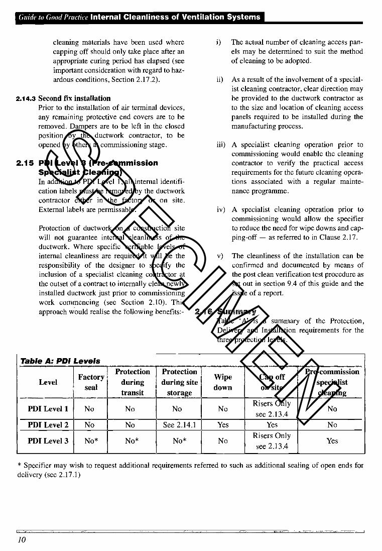
21 SurmaryTable 'A' is a summary of the Protection,Delivery and Installation requirements for thethree protection levels.
Table A: PDI LevelsProtection 1 Protection
—Pre-commission
Factoryduring during site Wipe Cap off
specialistLevelseal down on sitetransit storage cleaning
PD! Level 1 No No No No Risers Only
see_2.13.4No
PD! Level 2 No No See 2.14.1 Yes Yes No
PD! Level 3 No* No* No* No Risers Onlysee 2.13.4
Yes
* Specifier may wish to request additional requirements referred to such as additional sealing of open ends fordelivery (see 2.17.1)
I; 't',<--, - --- S'---- '-.- -,
10
SPECIMEN

Internal Cleanliness of Ventilation Systems Guide to (;d Practice
2.17 Other important considerations
2.17.1 Factory/Site sealing of ductworkIn certain circumstances such as clean rooms,the specifier may require that the internal sur-faces of new ductwork are protected duringtransportation and site storage. This can beachieved by factory sealing all ductwork eitherby blanking or capping duct ends, bagging smallfittings, surface wrapping or shrink wrapping(see important consideration with regard to haz-ardous conditions, Clause 2.17.2). The specifiermust clearly specify this requirement to theductwork contractor and also to the MainContractor in terms of ensuring dry/clean stor-age and working areas.
2.17.2 Hazardous conditionsIn certain concentrations some cleaning materi-als and sealants can pose a risk to operatives.The Control of Substances Hazardous to Health
Regulations (COSHH) require employers toassess the risk to employees' health from usinghazardous materials and take precautions tominimise that risk. For example, when usinginternally applied solvent based sealants andadhesives on site, ducts should only be capped-off after an appropriate curing period haselapsed (normally a minimum of 24 hours).Ducts should be left to naturally ventilate priorto sealing-off the installed ductwork.
2.17.3 Site drilling of ductworkSwarf will be generated during the installationand possibly during commissioning/airbalancing e.g. test probe covers. Some swarfwill therefore remain inside the ductwork unlessa form of on-going specialist cleaning is speci-fied.
SECTION 3Design and Access to theinternal surfaces of theVentilation System3.1 HVCA specification DW/144 covers the provi-
sion of access panels for the inspection!servicing of adjacent items of in-line equip-ment. In a new ductwork system these are theonly access panels that a ductwork contractorwill provide unless there is a clear indication bythe designer/specifier as to their requirementsfor access to facilitate cleaning survey/inspec-tion (see Table 1 of this Guide) or cleaningactivity (see Table 2 of this Guide).
3.2 This section gives general guidance egardingprovisions for the system hygieneinspection/testing and system cleaning of bothnew and existing ductwork systems. The loca-tion of access panels for these purposes is setout in Tables 1 and 2. A specifier may considervariances to this advice having taken due regardof specific cleaning methods. In the case of newductwork systems, alternative guidance to thatgiven in Table 2 is also provided for thedesigner/specifier in DW/144, Appendix M(Revised).
3.3 The precise location, size and type of accesswould be dependant upon the system design andthe type of ductwork cleaning, inspection andtesting methods to be adopted. The advice of thespecialist cleaning contractor should be soughtat an early stage.
3.4 At design stage, the access panels desiredshould be clearly shown on the design drawingsto avoid ambiguity. Alternatively, instructionsshould be written into a project for pre-commis-sioning cleaning to be carried out and the nec-essary access doors to be installed by the clean-
ing specialist at that stage.
3.5 It is essential to note that the tabulated accessschemes cannot necessarily be used prescrip-tively since consideration must be given by thedesigner to the particular building, services andarchitectural interfaces and system require-
SPECIMEN

(,iiide lo Good Practice Internal Cleanliness of Ventilation Systems
ments. The designer's responsibility under theCDM regulations is to ensure that the systemcan be safety maintained, inspected andcleaned.
3.6 It is for the designer and the other project partiesresponsible for the implementation of thedesign, under CDM "cascade" principles, toensure that access panels are not obstructed bypipework, cable trays or any other obstacle dur-ing the building process. Consideration shouldbe given to the future use of the building includ-
ing occupation.
3.7 Access panels in accordance with DW/144should be suitable for the purpose for whichthey are intended. They should incorporatequick release catches, sealing gasket and ther-mal, acoustic and fire-rated insulation proper-ties equal to that of the duct to which the panelis fitted. The panel and aperture should be freeof any sharp edges.
3.8 For system hygiene inspection and testing andfor system cleaning, Tables 3 and 4 indicate theniinimum sizes of access panel required.
3.9 Generally it is acceptable to access a branchduct for cleaning by removal of the flexible ductthat connects to the grille plenums.
Table 1: Guidance as to location ofaccess panels for inspection purposes
(Circular) (Downstream)Filter Sections One side (for removal
purposesAir Turning Vanes None
Changes of Direction None
In Duct Fans/Devices One side
3.10 For the purpose of cleaning the ventilation sys-tem and its component parts, the recommendedlocation of the access panels, size and type istaken from European draft standard ENV 12097"Requirements for ductwork components tofacilitate maintenance of ductwork systems".
3.1 1 This document reproduces this information inpart, so as to establish the location, size and typeof access panels, for new build and upgrade ofexisting ductwork systems. These details aregiven in Tables 2, 3 and 4.
Table 2: Guidance as to location ofaccess panels for cleaning
Control Dampers
Fire Dampers
Attenuators (Rgjar)Attenuators (Circular)
Both sides
One side
15iOne side
Filter Sections Both sides
Air Turning Vanes Both sides
Changes of Direction One side
In Duct Fans/Devices Both sides
Notes to Table 2
1. Other than in the locations shown in Table 2,access panels should be located as a minimumevery lOm in horizontal ductwork systems forthe purpose of normal usage but not greater thanim from the throat of a square 90° bend.
2. In kitchen extract systems or other areasdeemed by the specifier to require greateraccess, panels should be installed at a maximumof 3m centres. See also Section 7.
3. In the case of vertical ductwork, an access open-ing at the bottom and top of each riser should beprovided as a minimum.
4. Access panels can be positioned to allow accessto more than one component depending on duct-work dimensions, distance between componentsand the cleaning technique used.
5. Access panels should normally be positionedwithin im of the item to be cleaned.
Control Dampers
Fire Dampers
Heating/Cooling Coils
Attenuators
Attenuators
One 300mm x 200mm
One 300mm x 200mm
One 300mm x 200mm
One 300mm x 200mm
(DownsfreaOne 300mm x 200mm
12
SPECIMEN

Internal Cleanliness of Ventilation Systems Guith' to Good Prae/ic'
6. A change of direction is deemed to be a 900bend and branches. With regard to circular duct-work it is not necessary for there to be an accesspanel on every change of direction.
Table 3: Recommended size ofOpenings (Rectangular & Flat Oval)
Duct size up to
longest sidemajor axis
mm
Minimum dimension
of openings
mm
200
500
1000
Duct Entry*
300
400
450
600
100
200
450
500
Table 4: Recommended size ofOpenings (Circular)
Duct size up to
mm
Minimum dimensions
of openingsmm
315
5001000
Duct Entry*
300
400
450
600
100
200
450
500
Note.* Duct entry to be determined by localconditions/requirements and may be required in duct-work sizes above 1000mm longest side majoraxis/diameter subject to risk assessment. Also seeSection 10.
SECTION 4Specific Considerationsfor System ComponentsAir Handling Units & Other SystemComponents4.1 To obtain satisfactory conditions of cleanliness
all the components associated with the ventila-tion system should be included in specificcleaning and maintenance procedures.
Fresh Air Inlet4.2 Inlets should be protected by weather louvers
backed by maximum 12mm mesh and situatedaway from potential sources of contamination.Heavy contamination within inlets prior to fil-ters is common and may include insects, feath-ers, bird droppings, nesting materials, windblown leaves, grass, soil and paper. Inlets nearroads may suffer carbon based deposits.
4.3 Water entry as droplets or condensation can sup-port mould growth in inlets and make dirtdeposits difficult to remove, as well as causingrust and permanent water marking.
4.4 The provision of extra access panels may berequired to give operator entry to removedeposits by scraping, vacuuming, brushing orwet methods and to repair louvers, mesh andcorrosion damage.
4.5 Where significant bird contamination or mouldproblems are encountered a preliminary disin-fection before starting work may be requiredand appropriate protection provided for clean-ing operatives.
Access to Air Handling Units4.6 Access to all sections of the air handling unit is
required for adequate cleaning. Occasionallythere is no usable access door to the spacebetween sections, for example heating and cool-ing coils. In this event extra access panels mayhave to be installed subject to the design of theunit. Defective door seals are a common andsignificant source of inward dirt leakage.
SPECIMEN

(,ziidc to (iod I'radice Internal Cleanliness of Ventilation Systems
All filters should be correctly installed andmaintained. Incorrectly fitted and collapsed fil-ters are a common cause of ductwork systemcontamination.
Air handling units, ductwork and other systemcomponents may be lined with Machine-MadeMineral Fibre (MMMF) which may or may notbe protected by a coating, foil or fabric.Damaged linings releasing particles into the airsystem are common. Foam may be also be usedas a lining. This can break down with age torelease fine particles.
4.9 Many imings are porous and have the capacityto absorb dirt. They require thorough but carefulvacuum cleaning with a soft brush head toremove dirt without causing damage. Completedirt removal is unlikely to be achieved.
4.10 Where moisture is present significant microbio-logical growth within the lining is possible.Biocidal treatment is an option, but may not befully effective due to the porous surface. Itwould be difficult to assess the full extent of thedamage/reaction caused by moisture or clean-ing/biocidal chemicals.
4.1 1 The existing condition of the lining, or potentialdamage caused by cleaning activities, maynecessitate the removal, repair or coatmg of theductwork lining interior.
Moisture4.12 Humidification and condensation on chilled sur-
faces and leakage can cause dampness or inextreme cases standing water resulting in corro-sion or excessive microbial growth. Similarproblems can occur at droplet eliminators. Poordrainage of condensate from chilled coil driptrays may require cleaning of drain lines andtraps. Treatments to prevent microbiologicalgrowth contaminating and blocking trays anddrain lines are a possible option.
4.13 Design and maintenance considerations to pro-tect against proliferation of legionella speciesare dealt with in ACOP L8 and NHS Guidance(see Appendix E).
Heating and Cooling Coils4.14 Those with very closely spaced fins and/or
which are very deep, can suffer blockage due toaccumulated dirt, corrosion and hardnessdeposits. They are prone to severe deteriorationof the fms. Coils located before filters are par-ticularly vulnerable.
4.15 Vacuum brushing, compressed air blast, wash-ing, water jetting, and the application of chemi-cal cleaning methods, singly or in combinationmay be required. Care must be taken to avoiddamage to fins.
Fans4.16 Fans, motors and drives may be heavily conta-
minated especially if oil or grease has leaked.Impellers may have heavy deposits on theblades. For full insitu cleaning, partial disman-tling and, possibly, the creation of extra accesspanels in fan casings, subject to manufacturerapproval, may be required.
Sound Attenuators4.17 Sound attenuators (also called silencers) may be
located within air handling plant or situatedremotely in ducts. These usually have liningscovered with woven fabric or perforated sheetmetal. Dirt readily accumulates in silencers andtheir porous nature makes complete cleaningimpossible. Careful vacuum brushing with asoft brush head or gentle application of com-pressed air are possible methods.
4.18 Where damage has occurred which may allowthe release of MMMFs, consideration should begiven to repair or replacement.
Turning Vanes, Volume Control Dampers,Fire Dampers4.19 These tend to accumulate dirt which can affect
their operation and may require access panelsadded to one or both sides to allow full cleaningand surface restoration.
4.20 Manually set volume control dampers shouldhave the 'as found' setting marked indelibly toaid resetting.
Filters4.7
Linings4.8
14
SPECIMEN

Internal Cleanliness of Ventilation Systems Guide lu Goud ('ruclice
4.21 Fire dampers should be physically cleaned, butinspection and functional testing of smoke/firedampers should be separately specified.
In-duct Heat Exchanger Coils4.22 Lack of access for inspection and routine clean-
ing can result in these being blocked with dirt,restricting air flow through them (methods asused for air handling units apply). Additionalaccess panels to give access to both sides of thecoil will usually be required.
Flexible Ducts4.23 Flexible ducts trap dirt in the corrugations. This
dirt can be difficult to completely remove if the
corrugations are deep and/or compressedtogether. Light weight foil, plastic flexible oraged flexible are liable to damage. Cleaningmethods must be adjusted to account for thetype of flexible duct. Brush methods require softbristle brushes and gentle application.Compressed air methods may require a pressurereduction to avoid tearing the duct material.
4.24 It may be necessary to remove and extend flex-ible ducts to release dirt from folds.
4.25 Decay of the material of construction, or diffi-culties in releasing flexible ducts from theirconnection spigots without causing damagemay make replacement a better option thancleaning.
Diffusers and Grilles4.26 Where possible these should be removed for
cleaning. Washing to remove grease and tobac-co staining may be required.
4.27 Diffuser/grille locations and orientation shouldbe marked or recorded if they are to be takenaway for washing, so that they can be returnedto the correct location. Opposed blade dampersshould have the 'as found' setting marked to aidresetting.
4.28 Certain grille and diffuser arrangements may beinstalled such that they cannot be practicablyremoved for cleaning, e.g. linear diffusers orthose trapped by partition walls. Insitu cleaningby air line and extraction to capture dislodgeddeposits may be used.
4.29 Diffusers may have plenum boxes, possiblycontaining dampers behind them, which alsorequire cleaning. Access will be required to per-mit cleaning or air jetting and extractionmethods.
Terminal Equipment4.30 Equipment such as fan coils, mixing boxes,
CAY, VAY, induction units and unit air condi-tioners may be included in a cleaning pro-gramme.
4.31 Wall and sill mounted equipment is frequentlyobstructed by difficult to move furniture and fit-tings, preventing or hindering access for clean-ing. Responsibility for moving obstructionsshould be defined by the Specifier.
4.32 Ceiling mounted equipment may be obstructedby services and structures preventing the open-ing of access panels and withdrawal of internalcomponents. Some terminal units have filterswhich may require cleaning or which are dis-posable. Contractual responsibility for supply-ing replacement filters will require definition bythe Specifier.
4.33 Terminal units may be lined or include attenua-tor sections. Maintenance activity, ageing anderosion by air flow may have resulted in dam-age to the lining allowing fibre escape. If dam-age to the lining occurs remedial action shouldbe taken immediately. The lining may haveaccumulated dirt within its matrix. The limitedaccess to all air passages, especially labyrinthpassages in attenuators within terminal unitsand the presence of delicate porous linings canprevent total dirt removal.
4.34 Gentle vacuum brushing or air jetting, plus highvolume extraction may be required. Some unitshave air jet nozzles or small air passages whichbecome blocked with dirt. This dirt can form ahard deposit which requires mechanicalremoval with suitable tools to chip or ream itaway. Jet nozzles may also require washing.
SPECIMEN
(;uid(' , (;d Praclice Internal Cleanliness of Ventilation Systems
4.35 It is important for the Specifier to define theextent of cleaning for Induction Units e.g.whether secondary and mixed air surfaces onlyare included or whether typically less accessibleprimary air surfaces (plenum box) are alsoincluded.
Plenum Void4.36 Ceiling and floor void plenums may be used as
an integral part of the air distribution systemand should therefore, be subject to the samehygiene consideration as other system compo-nents. Regard should be given to the selection ofcleaning technique(s) in view of the differentconstruction materials used.
SECTION 5System Testing(InspectionlMonitoring)5.1 The Workplace (Health, Safety and Welfare)
Regulation 5 imposes a duty to clean mechani-cal ventilation systems "as appropriate." TheWorkplace Regulations are accompanied by anApproved Code of Practice (ACOP) whichgives guidance on how compliance with the reg-ulations can be achieved. Regulation 3 of theManagement of Health & Safety at WorkRegulations 1999 imposes a duty on everyemployer to conduct a risk assessment and thetesting procedure within this guide would assistin assessing some of the risks in relation to ven-tilation systems.
5.1.1 ACOP 22(A) States that regular mainte-nance (including, as necessary, inspection, test-ing, adjustment, lubrication and cleaning)should be carried out at suitable intervals.
5.1.2 ACOP 33 States that "Mechanical ventilationsystems (including air conditioning systems)should be regularly and properly cleaned, testedand maintained to ensure that they are keptclean and free from anything which may conta-minate the air."
5.2 A testing procedure is defined in this guidewhich may be used to establish whether or not itwould be appropriate to clean a mechanical ven-tilation system. This provides one reasonablepracticable way of satisfying the Regulation andACOPs relevant to the cleanliness of ventilation
systems. Specific guidance is given in Appendix D
5.3 Testing is a specialist activity which is not nor-mally covered within the scope of a standardmaintenance schedule.
5.4 Many different methods of testing are offeredby service providers. It should be noted thatthere is a clear difference between tests to mon-itor ventilation system surface condition andtests to monitor 'ventilation air quality'. Surfacecondition tests will indicate the potential for the
SPECIMEN
Internal Cleanliness of Ventilation Systems (:iidc lo Good Prw/ice
system to release contaminants into theair at any point in the future, whilst airquality tests will indicate contaminantsthat are actually in the air, but only atthe time of collecting the sample.Additionally, the source of these conta-minants can only be defined where sam-p1mg arrangements are controlled care-
fully.
5.5 The owner or operator should select thetype(s) of test(s) and frequency to beincluded within their testing regime tosuit the particular requirements of thebuilding served by the ventilation system. Theregime should be reviewed regularly (e.g. annu-ally), to take into account any changes in thebuilding use, legislation and/or health and safe-ty guidance.
5.6 The HVCA's Ventilation Hygiene GroupBranch have investigated many different meth-ods for 'ventilation system surface condition'testing to establish an objective method fordetermining when a ventilation system is con-sidered dirty in terms of particulate and hencewhen it would be appropriate to clean. Twoalternative testing methods are recommended asfollows:-
1. Deposit Thickness Test (DT.T.)2. Vacuum Test (V.T.)
Separate testing and contaminant levelsspecifically for kitchen extract systems aredetailed in Section 7.
5.7 The D.T.T. method determines the mean surfacedeposit m terms of micron thickness, whereasthe V.T. method determines the mean depositweight in grams per m2. Both test methods pro-vide an objective method of measuring internalduct floor surface deposits.
5.8 The tests, which are detailed in Appendix D, arerecommended to be repeated at intervals notexceeding 12 months. Depending on the qualityof input air, the level of filtration and sensitivityof the served area, the frequency of inspectionand testing may be increased or decreased. Forexample, a rolling programme of inspections
may be devised such that individual systems areinspected within a 3 year period; with more fre-quent inspections of sensitive areas eg air han-dling units, filters, etc. The frequency of thetests should be reviewed annually.
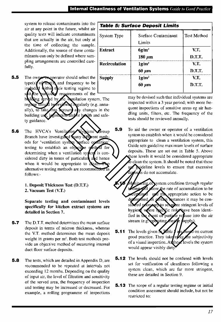
5.9 To aid the owner or operator of a ventilationsystem to establish when it would be consideredappropriate to clean a ventilation system, thisGuide sets guideline maximum levels of surfacedeposits. These are set out in Table 5. Abovethese levels it would be considered appropriateto clean the system. It should be noted that theseare guideline levels to ensure that excessivedeposits do not accumulate.
5.10 Monitoring of system condition through regulartesting will allow the rate of accumulation to beascertained and the appropriate action to bedetermined. In certain instances it may be con-sidered necessary to set more stringent levels ofhygiene where specific risks have been identi-fied in the event of particle release into the airstream (e.g. operating theatre supply).
5.1 1 The levels given in Table 5 are based on currentgood practice. They take away the subjectivityof a visual inspection. At these levels the system
would appear visibly dirty.
5.12 The levels should not be confused with levelsset for verification of cleanliness following asystem clean, which are far more stringent,these are detailed in Section 9.
5.13 The scope of a regular testing regime or initialcondition assessment should include, but not berestricted to:
Table 5: Surface Deposit Limits
System Type Surface Contaminant
Limits
Test Method
Extract
Recirculation
Supply
6g/m2
180 pm
lg/m2
6Opm
lg/m260 pm
V.T.
D.T.T.
V.T.
D.T.T.
V.T.
D.T.T.SPECIMEN

Guide to Good Practice Internal Cleanliness of Ventilation Systems
1. Provision of suitable access points.
2. Visual inspection.This may be assisted bythe use of equipment such as cameras,endoscopes and robotic CCTV with appro-priate records such as photographs andvideo footage.
3. Quantitative surface dust measurement bythe D.T.T. or V.T. method. Where grease oradhered deposits are clearly the issue thenonly the D.T.T. method, or the wet filmthickness test method (W.F.T.T.) detailed inSection 6, should be used. In view of thedifficulty in measuring deposits on curvedsurfaces, visual comparison can be madebetween the appearance of the curved sur-face and an appropriate flat surface. A min-imum of three test points per system shouldbe included with no less than one test pointper 50 linear metres of ducting up to 300linear metres and no less than one test pointper 100 linear metres thereafter. An aver-age should be calculated across all testsconducted on each system and used todetermine whether it is appropriate to cleanthe system. However, individual resultsthat are excessively high may indicate aneed for local attention.
4. The following components should be sub-ject to cleanliness inspection as a mini-mum:
• Fresh air intakes, air handling unit includ-ing filters and coils) and selected in-ductplant and ancillaries such as attenuators,fire dampers, volume control dampers,heat exchangers, VAV boxes etc.
• A selection of ductwork, including (but notlimited to) changes of direction, termina-tions, straight horizontal and vertical ducts.
• A selection of terminal equipment such asflexible ducts, grilles, diffusers and equip-ment e.g. induction and fan coil units.
The number of inspection locations andtests should be clearly defined by thespecifier.
5. The client should be given the opportunityto witness the sample testing of ductworksurfaces.
SECTION 6Cleaning Methods6.1 This guide is not intended to be prescriptive in
relation to the method of cleaning, as there aremany existing and emerging technologiesavailable depending upon the type of deposit tobe removed. To conform with this guide, theactual application of the methods listed inTables 6 and 7 must be capable of achieving therequired result.
6.2 Considerations when using dry cleaningmethods
In all cases where Note A appears, the particu-late should be collected using an air movementand containment machine. This will generallyrequire appropriate filtration and should assistin the containment of contaminants.
3 Considerations when using wet cleaningmethods
• Moisture can assist in the growth ofmicro-organisms and the system shouldbe thoroughly dried prior to commission-ing/re-commissioning.
4 The introduction of cleaning chemicalsor biocides should only be consideredwhere a risk assessment has been carriedout, the details recorded and any adverseeffects of the applied chemicals havebeen assessed and determined withappropriate safe procedures set out in aformal method statement.
• Steam cleaning and high pressure water-wash are not reconmiended for ductworkthat is situated above ceilings or in sensi-tive areas unless carried out in a controlledmanner to contain leakage. Again,procedures must take account of operativesafety and should be set out in writtenform.
• Careful consideration should be given tothe use of chemicals and/or water for
SPECIMEN

Internal Cleanliness of Ventilation Systems Guide to Good Practice
surfaces that are porous e.g. internally-lined ductwork, attenuators, fibre boardductwork etc., as permanent damage mayresult.
• Before applying wet cleaning methodscare should be taken to ensure that con-densed vapours and cleaning fluids canbe removed from the ductwork system.
Table 7: Wet Cleaning Methods
Generic Name Method of Removing
Deposit
Wet Vacuum Suction
Chemical Clean Softens or dissolves
deposits
Hand Wash Washing of internal
surface usingappropriate medium
Steam/High pressurewater wash
High pressure systemused to dislodge!
dissolve deposits
Table 6: Dry Cleaning Methods
Generic Name Energy Source Method of Removing Deposit
Air Whip/Skipper Ball (A)
Air Lance (A)
Air Nozzle (A)
Compressed Air(Low Volume)
Compressed Air(Low Volume)
Compressed Air(High Volume)
Hand Wipe Manual
A rubber hose or plastic ball that underpressure agitates the wall of the ductwork
Usually an air gun with a trigger that isable to direct compressed air locally
Usually a plastic or metal ball placed onthe end of a flexible hose. Compressed airleaving small openings in the ball propelsthe hose forward inducing the nozzle toclosely traverse the internal surface of theduct.
Wiping of the surface using a mediumappropriate to the purpose
Removing heavy deposits by hand scraping
Brushing the surface using a brushappropriate to the purpose
Suction
Brushing the surface of the ductwork usingmechanical action
Brushing the surface of the ductwork usingmechanical action and compressed air
Hand Scrape
Hand Brushing
Hand Vacuum
Mechanical Brushing (A)
Mechanical Brush and AirTechnology Combined (A)
Manual
Manual
Electricity/Manual
CompressedAir andlor Electricity
Compressed Air/Electricity
SPECIMEN
Guide' to Good Practice Internal Cleanliness of Ventilation Systems
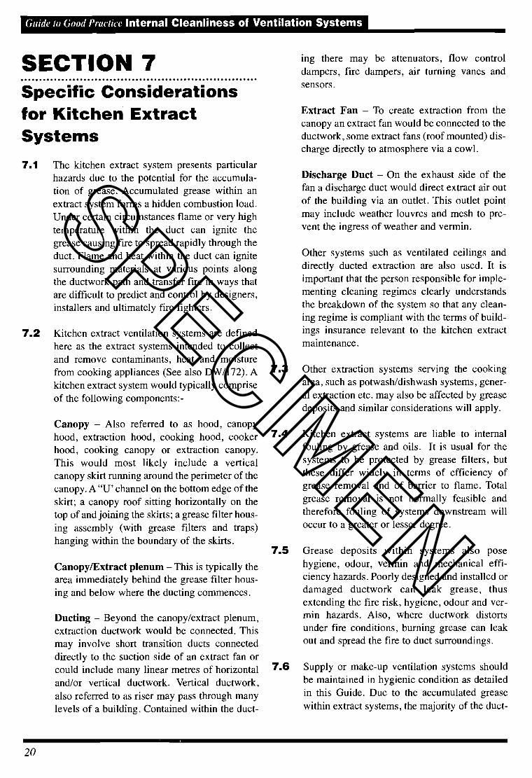
SECTION 7Specific Considerationsfor Kitchen ExtractSystems7.1 The kitchen extract system presents particular
hazards due to the potential for the accumula-tion of grease. Accumulated grease within anextract system forms a hidden combustion load.Under certain circumstances flame or very hightemperature within the duct can ignite thegrease causing fire to spread rapidly through theduct. Flame and heat within the duct can ignitesurrounding materials at various points alongthe ductwork path and transfer fire in ways thatare difficult to predict and control by designers,installers and ultimately fire fighters.
7.2 Kitchen extract ventilation systems are definedhere as the extract systems intended to collectand remove contaminants, heat and moisturefrom cooking appliances (See also DW/172). Akitchen extract system would typically compriseof the following components: -
20
Canopy — Also referred to as hood, canopyhood, extraction hood, cooking hood, cookerhood, cooking canopy or extraction canopy.This would most likely include a verticalcanopy skirt running around the perimeter of thecanopy. A "U' channel on the bottom edge of theskirt; a canopy roof sitting horizontally on thetop of and joining the skirts; a grease filter hous-
ing assembly (with grease filters and traps)hanging within the boundary of the skirts.
Canopy/Extract plenum — This is typically thearea immediately behind the grease filter hous-ing and below where the ducting commences.
Ducting — Beyond the canopy/extract plenum,extraction ductwork would be connected. Thismay involve short transition ducts connecteddirectly to the suction side of an extract fan orcould include many linear metres of horizontaland/or vertical ductwork. Vertical ductwork,also referred to as riser may pass through manylevels of a building. Contained within the duct-
ing there may be attenuators, flow controldampers, fire dampers, air turning vanes andsensors.
Extract Fan — To create extraction from thecanopy an extract fan would be connected to theductwork, some extract fans (roof mounted) dis-charge directly to atmosphere via a cowl.
Discharge Duct — On the exhaust side of thefan a discharge duct would direct extract air outof the building via an outlet. This outlet pointmay include weather louvres and mesh to pre-vent the ingress of weather and vermin.
Other systems such as ventilated ceilings anddirectly ducted extraction are also used. It isimportant that the person responsible for imple-menting cleaning regimes clearly understandsthe breakdown of the system so that any clean-ing regime is compliant with the terms of build-ings insurance relevant to the kitchen extractmaintenance.
7.3 Other extraction systems serving the cookingarea, such as potwash/dishwash systems, gener-al extraction etc. may also be affected by greasedeposits and similar considerations will apply.
7.4 Kitchen extract systems are liable to internalfouling by grease and oils. It is usual for thesystems to be protected by grease filters, butthese differ widely in terms of efficiency ofgrease removal and of barrier to flame. Totalgrease removal is not normally feasible andtherefore fouling of systems downstream willoccur to a greater or lesser degree.
7.5 Grease deposits within systems also posehygiene, odour, vermin and mechanical effi-ciency hazards. Poorly designed and installed ordamaged ductwork can leak grease, thusextending the fire risk, hygiene, odour and ver-min hazards. Also, where ductwork distortsunder fire conditions, burning grease can leakout and spread the fire to duct surroundings.
7.6 Supply or make-up ventilation systems shouldbe maintained in hygienic condition as detailedin this Guide. Due to the accumulated greasewithin extract systems, the majority of the duct-
SPECIMEN

Internal Cleanliness of Ventilation Systems Guide to Good Praclice
work cleaning will be by manual rather thanmechanical methods. At the time of system sur-vey, a detailed schematic should be provided,highlighting any areas which are inaccessibleand therefore, will remain uncleaned. The clientmust be advised of any inaccessible areas, thereason for their inaccessibility and, if possible,the likely cost to provide full and free access. Itis the clients responsibility to highlight this totheir insurer or other relevant third party, ifrequired, who must confirm whether an excep-tion to the total cleaning in accordance withTRI19 is acceptable.
7.7 This section of the Guide provides specificadvice on how to clean and maintain kitchenextract systems, but similar consideration willapply to non-kitchen areas that might be affect-ed by grease and/or oil deposits.
Design and Access to theInternal Surfaces of theKitchen Extract System
7.8 Advice is provided in HVCA DW/172:Specification for Kitchen Ventilation Systems(2005).
7.9 Internal surfaces of kitchen extract systemsshould be free of irregularities, all of whichmake grease accumulation more likely andcleaning more difficult.
7.10 It is essential that a kitchen extract ductworksystem, and canopy/extract plenum, is providedwith access panels of sufficient number, qualityand size to enable unrestricted access for regu-lar cleaning and inspection of the internal sur-faces and in-line components.
7.1 1 Location of access to the internal surfaces of akitchen extract system is dependent on a num-ber of design and operational considerations
• Design and location of ductwork
• Building design and construction materials
• Location of kitchen within the building
• Location of extract fan and accessibilityfor maintenance
• Accessibility to physically reach the duct-work
• Any building modifications and currentuses that may restrict access
• Location and number of system compo-nents requiring access.
7.12 Access panels should be suitable for the purposefor which they are intended. The panels andframes should be constructed of the same mate-rial as the ductwork. As a minimum they should
incorporate quick release catches, sealing gas-ket and thermal, acoustic and fire rated insula-tion properties equal to that of the duct to whichthey are fitted. Particular consideration must begiven to maintaining the fire integrity of fire-rated ductwork. The recommendations of themanufacturer or specialist fire protection advis-er should be followed where appropriate.
7.13 Access panels should be as large as the duct sizepermits to a maximum of 460mm x 610mmwithout weakening the structure of the system.Openings should not be obstructed by otherbuilding services, stored equipment or by thefabric of the building. The panel and apertureshould be free of any sharp edges.
7.14 Access panels should be fitted at the side of theduct, a minimum of 10mm above the base tominimise the risk of grease leakage.Exceptionally, they may be fitted on the top ofthe duct, but due consideration should be givento the accessibility of the panel. Where accesspanels must be fitted to the underside of a duct,particular care must be taken to ensure a leak-free fit and notice should be affixed warning ofthe risk of oil being released on opening thepanels. In designing systems due considerationshould be given to providing physical unob-structed access to all access panels.
7.15 Access panels should be fitted on either side ofin-line components, as detailed in Table 8, toallow physical entry to clean these intricate sur-faces. This Table includes components, such asfire dampers and attenuators, which are not nor-mally recommended to be installed, but areoften found in practice.
21
SPECIMEN

Guide to Good Practice Internal Cleanliness of Ventilation Systems
Notes to Table 8Additional builders work hatches mayneed to be fitted in ceilings/walls in exist-ing installations, or provided for in newconstructions. Consideration should alsobe given to safe high level access to exter-nal ductwork.
2 Access openings for cleaning purposes aregenerally required at a maximum of 3metre centres and/or at each change ofdirection. This distance should be reducedwhere the size of the duct prevents ade-quate cleaning by hand, where there areseveral changes in direction or where otherexternal features restrict the positioning ofpanels.
3 Internal kitchen extract risers often requireaccess doors fitted on at least each floorlevel so that all internal surfaces can bereached and fire dampers, where fitted,cleaned and checked. In older buildingsthis may require additional builders works(e.g. hatches through brickwork) to reachthe riser ducts (see 7.6).
4 Extract fan design should allow thoroughcleaning of impellor blades and internal
22
surfaces without the need for dismantling,i.e. ductwork with access panels should beprovided immediately upstream and down-stream. Larger fans should be designedwith panels in the casing. Similarly, attenu-ators or other in-line fittings likely toobscure cleaning activity should be provid-ed with access on both sides.
5 Guideline access frequency given abovemay be reduced where remote cleaningmethods and personnel entry can be ade-quately applied. However, in all instancesevery section of ductwork should be capa-ble of verification inspection.
6 Design consideration should be given tothe provision of safe access to the down-stream side of discharge grilles, bird guardmesh and louvres.
7 Fire dampers are not fitted in new installa-ons,but may still be found in older systems.
7.16 During cleaning maintenance it is essential toensure that the mechanical and any fire integri-ty of access provision is maintained. Accesspanels should be identified and marked on aschematic sketch (see Verification ofCleanliness below). Control procedures shouldensure that all access panels are properlyreplaced after cleaning, and that any fire protec-tion removed for cleaning (e.g. cladding board)is properly re-fitted both at the duct and at anybuilders work. The number of access panelsremoved at any one time should be kept to aminimum. All panels should be replaced at theend of the working shift.
7.17 Designers, installers or specialist cleanersshould define and justify the number of accesspanels to be fitted to an installation in line withthis Guide.
System Testing(Inspection/Monitoring)
7.18 The Health & Safety Executive and industryand insurance guidance and regulations (seeAppendices B & E) stipulate that kitchen extractsystems should be kept clean to minimise fireand other risks. This Guide now provides amethod of measuring and definingcleanliness and dirtiness as a benchmark forgood practice.
Table 8: Location of Access Panelsfor Cleaning and Inspection Purposes
Volume Control Dampers Both sides
Fire Dampers Both sides
(see Note 7)
Attenuators Both sides
Changes in Direction Both sides
Filter Sections Both sides
Horizontal Ducts Generally every
Risers
3 metres (see Note 2)
Top and bottomas a minimum
(see Note 3)
Extract Fans Both sides (see Note 4)
Discharge grille/mesh One side (see Note 6)
SPECIMEN
Internal Cleanliness of Ventilation Systems Guide to Good Practice
7.19 The HVCA Ventilation Hygiene Group Branchhas investigated a variety of methods for testingductwork system internal surfaces to measuregrease deposits and recommends the Wet FilmThickness Test (W.F.T.T.) measurementmethod. This method is described in AppendixD.3.
7.20 The Deposit Thickness Test (D.T.T), asdescribed in Section 5, may also be used andmay be necessary in the case of extremely hard-baked, carbonised, deposits. It is however lessreliable for soft or liquid deposits and the find-ing of hard-baked deposits would normally indi-cate a requirement to clean or in the case ofcleanliness verification a requirement to re-clean.
7.21 The testing methods provide an objective,repeatable and verifiable measurement of greasedeposits, and overcome the subjectivity of visu-al inspection alone.
7.22 It is recommended that testing be carried out atintervals not exceeding 12 months. Monitoringof grease deposits may need to be carried outmore frequently if it is necessary to establish aprecise definition of required cleaning frequen-cies. The cleaning frequency required should beestimated by a specialist service provider and/orclient on initial inspection or assessment andsubsequent pre-clean testing will confirmwhether the initial predicted frequency is cor-rect or requires adjustment.
7.23 Measurements should be taken at the followinglocations where practicable:
• Canopy/Extract plenum behind filters
• Duct 1 metre from canopy
• Duct 3 metres from canopy
• Duct midway between canopy and fan
• Duct upstream of fan
• Discharge duct downstream of fan
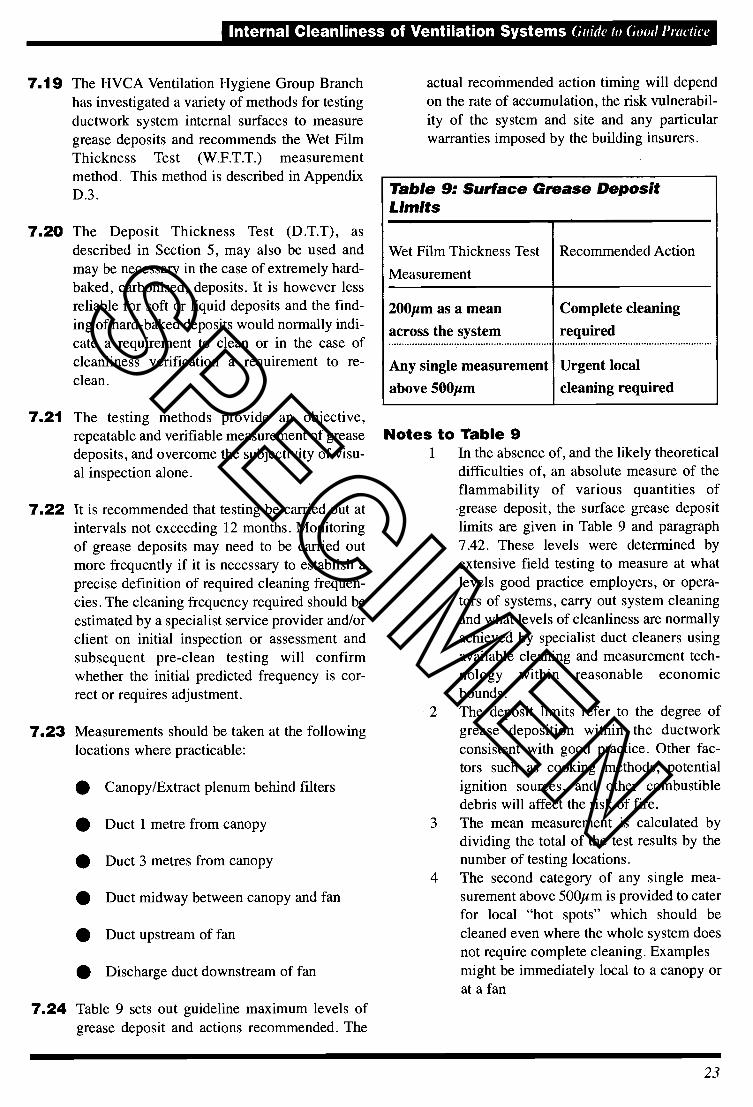
7.24 Table 9 sets out guideline maximum levels ofgrease deposit and actions recommended. The
actual recommended action timing will dependon the rate of accumulation, the risk vulnerabil-ity of the system and site and any particularwarranties imposed by the building insurers.
Table 9: Surface Grease DepositLimits
Wet Film Thickness Test
Measurement
Recommended Action
200pm as a meanacross the system
Any single measurementabove 500pm
Complete cleaning
required
Urgent local
cleaning required
Notes to Table 9In the absence of, and the likely theoreticaldifficulties of, an absolute measure of theflammability of various quantities of•grease deposit, the surface grease depositlimits are given in Table 9 and paragraph7.42. These levels were determined byextensive field testing to measure at whatlevels good practice employers, or opera-tors of systems, carry out system cleaningand what levels of cleanliness are normallyachieved by specialist duct cleaners usingavailable cleaning and measurement tech-nology within reasonable economicbounds.
2 The deposit limits refer to the degree ofgrease deposition within the ductworkconsistent with good practice. Other fac-tors such as cooking methods, potentialignition sources, and other combustibledebris will affect the risk of fire.
3 The mean measurement is calculated bydividing the total of the test results by thenumber of testing locations.
4 The second category of any single mea-surement above 500pm is provided to caterfor local "hot spots" which should becleaned even where the whole system doesnot require complete cleaning. Examplesmight be immediately local to a canopy orat a fan
23
SPECIMEN

Guide lo Good Pracliee Internal Cleanliness of Ventilation Systems
5 The extent of urgent local cleaning precip-itated by the presence of grease depositsabove 500pm should be subject to rea-sonable appreciation of the extent offouling and risk posed.
7.25 The surface grease deposits limits should not beconfused with the level set for Post - Clean ver-ification which is far more stringent anddetailed in paragraph 7.42.
7.26 Stand-alone, regular or post-clean testing canusefully be combined with inspection of otherkitchen extract system safety issues. If specifiedby a client, a service provider should provideevidence of competence to carry out suchinspection. Such inspection should include, butnot be restricted to:
1. Adequacy of filters and their regular main-tenance
2. Adequacy of regular cleaning of canopy,and associated drains and traps
3. Existence and visual condition of any firesuppression or detection system
4. Damage to fire protection
5. Ductwork grease leakage
6. Ductwork damage
7. Damage to or inappropriate ductwork fix-tures
8. Visual/audible check of fan operation
9. Rubbish/debris adjacent to system
10. Visual assessment of any special filtration
11. Discharge condition, including greasesplatter/staining
7.27 Such inspection should not be regarded as asubstitute for proper maintenance of plant suchas fans and fire suppression or detection sys-tems.
Cleaning Methods7.28 This guide is not intended to be definitive in
relation to the method of cleaning, as there aremany existing methods that can be applied intandem, and emergent new technologies.Examples of cleaning methods are listed inTable 10.
7.29 To conform with the Guide, the actual methodor methods must be capable of achieving therequired results, i.e. Post-Clean Verification, notonly on the internal surfaces of the extract ductbut also on system components.
7.30 When choosing the cleaning method, consider-ation should be given to operative safety and
Table 10: Examples of Cleaning Methodology
Generic Name Energy Source Removal Method
Hand wipe Manual Wiping the surface of the ductwork
Hand scrape Manual Removing heavy deposits by hand scraping
Chemical Manual Softens or dissolves deposits making themsuitable for hand scraping
High pressure water wash(steam)
Electrical orcompressed air
Vapour or liquid expelled at high pressurefrom lance to dislodge/dissolve deposits
Blasting (remote or direct)using suitable mediumas appropriate
Compressed air Blasting medium dislodges contaminantfrom duct and component surfaces to beremoved via vacuum techniques or highvolume filtered extraction.
24
SPECIMEN
Internal Cleanliness of Ventilation Systems Guide lo Good Proelice
also to effects on the surrounding environment,particularly where using wet cleaning methods,since grease/moisture can leak from the duct-work components and damage the surroundingfabric.
7.31 Steam cleaning and high pressure water wash-ing are not recommended for ductwork that issituated above false ceilings or in sensitiveareas, due to possible leakage of contaminantsfrom the duct, unless specifically designed forwet cleaning.
7.32 After applying wet cleaning methods careshould be taken to ensure that any condensedvapours and cleaning fluids are removed fromall parts of the system.
7.33 The use of chemical cleaning agents shouldonly be considered where a riskICOSHH assess-ment has been carried out (See Section 10), thedetails recorded and the effects of the appliedchemicals have been assessed on the materialconstruction, environment and for hazards tocleaning personnel.
7.34 It should be noted that it is not normally eco-nomically practicable to clean kitchen extractsystems to a "like new" bright metal conditiondue to substrate staining.
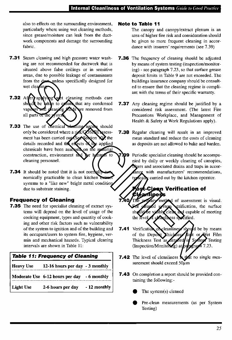
Frequency of Cleaning7.35 The need for specialist cleaning of extract sys-
tems will depend on the level of usage of thecooking equipment, types and quantity of cook-ing and other risk factors such as vulnerabilityof the system to ignition and of the building andits occupant/users to system fire, hygiene, ver-min and mechanical hazards. Typical cleaningintervals are shown in Table 11:
Note to Table 11The canopy and canopy/extract plenum is anarea of higher fire risk and consideration shouldbe given to more frequent cleaning in accor-dance with insurers' requirements (see 7.39)
7.36 The frequency of cleaning should be adjustedby means of system testing (inspection/monitor-ing) - see paragraph 7.23, so that surface greasedeposit limits in Table 9 are not exceeded. Thebuildings insurance company should be consult-ed to ensure that the cleaning regime is compli-ant with the terms of their specific warranty.
7.37 Any cleaning regime should be justified by aconsidered risk assessment. (The latest FirePrecautions Workplace, and Management ofHealth & Safety at Work Regulations apply).
7.38 Regular cleaning will result in an improvedmean standard and reduce the costs of cleaningas deposits are not allowed to bake and harden.
7.39 Periodic specialist cleaning should be accompa-nied by daily or weekly cleaning of canopies,filters and associated drains and traps in accor-dance with manufacturers' recommendations,typically carried out by the kitchen operator.
Post-Clean Verification ofCleanliness
7.40 The primary method of assessment is visual.For cleaned system verification, the surfaceshould be visibly clean and capable of meetingthe level of cleanliness specified.
7.41 Verification of cleanliness should be by meansof the Deposit Thickness Test or Wet FilmThickness Test as detailed in System Testing(Inspection/Monitoring) at paragraph 7.23.
7.42 The level of cleanliness is that no single mea-surement should exceed 50jm
7.43 On completion a report should be provided con-taining the following:-
• The system(s) cleaned
• Pre-clean measurements (as per SystemTesting)
25
Table 11: Frequency of Cleaning
Heavy Use 12-16 hours per day - 3 monthly
Moderate Use 6-12 hours per day - 6 monthly
Light Use 2-6 hours per day - 12 monthly
SPECIMEN

Giiith io Good Practice Internal Cleanliness of Ventilation Systems
• Post-clean measurements
• Photographic records
• Additional works carried out (if any)
• COSHH data on any chemicals used
• Recommendations for future cleaningrequirements
• Observations on the condition of the duct-work system
• A sketch or schematic of the system mdi-cating access panel and testing locationsand highlighting any uncleaned areas witha written explanation as to why the areacould not be accessed/cleaned (see para-graph 7.6)
7.44 If specified, additional kitchen extract safetyissues should also be reported (as outlined inparagraph 7.26).
7.45 The Post-Clean Verification of Cleanlinessreport should assist to serve as evidence of sys-tem status to insurance assessors,Environmental Health Officers, landlord'sagents, etc.
SECTION 8HazardousContamination8.1 A variety of specifically hazardous contami-
nants may be found in the ventilation systems,especially in industrial or laboratory LocalExhaust Ventilation systems (LEV) whose per-formance falis under COSHH Regulations.
8.2 Hazards may include precipitated toxic, car-cinogenic or otherwise hazardous particulate,condensed vapours and pathogenic micro-organisms.
8.3 Asbestos presents a variety of possible hazardsincluding:
• Contamination of ventilation system airand surfaces by asbestos fibres.
• System construction materials which maybe disturbed in gaining access to the sys-tem (e.g. cladding or panelling).
• Components such as flexible ductwork,flexible connections, gaskets, etc. contain-ing asbestos.
8.4 Asbestos must be removed and worked on onlyby licensed specialist contractors.
8.5 Specifiers must define any such likely or knownhazards in accordance with COSHHRegulations and contractors have a duty to sat-isfy themselves that hazards are known andaccounted for.
8.6 Specific risk assessments should be carried outand particular method statements provided todeal with hazardous contamination.
8.7 Any swab sampling required to meet specificneeds should be identified before work com-mences.
26
SPECIMEN
Internal Cleanliness of Ventilation Systems Guide to Good Practice
SECTION 9Verification ofCleanliness9.1 The primary method of assessment is visual. For
cleaned system verification the surface shouldbe visibly clean and capable of meeting thelevel of cleanliness specified.
9.2 Verification, where specified on general ventila-tion systems, should be by means of a vacuumtest (V.T.), as described in Appendix D, based onthe recommendations of the US National AirDuct Cleaners Association (NADCA) ACR 2005.A system will be considered acceptably cleanedif, following a V.T., a result of not more than.075g!m2 is achieved. This is equivalent to 0.75mg!100cm2 as per ACR 2005. Verification forkitchen extract systems is dealt with iii Section 7.
9.3 It should be noted that verification should takeplace immediately after cleaning to avoid anypossibility of post clean interference. The clientshould be given the opportunity to witness test-ing of ductwork surfaces.
9.4 For specialist pre-commission cleaning of newsystems the vacuum test cleanliness level of0.075g!m2 set out in paragraph 9.2 is appro-priate rather than the surface deposit limits(which determine dirtiness levels) set out inTable 5.
Completion Report9.5 On completion a comprehensive report should
be provided. This should clearly state the fol-lowing information:• The ventilation system(s) cleaned
••• Photographic support• Additional works carried out (if any)• COSHH data on any chemicals used for
cleaning or biocidal treatment
• Recommendations for future testing andcleaning requirements
9.6 For Kitchen Extract Systems a report should beprovided as set out in paragraph 7.43.
SECTION 10Health and Safety10.1 A Risk Assessment and Safety Method
Statement for the work should be preparedby a competent person and approved by theclient before allowing the work to be started.
10.2 COSHH assessments for any substances tobe used should also be made.
10.3 The Risk Assessment, Method Statement andCOSFIH assessments must be drawn to theattention of the operatives and their supervisors,and understood, before they commence work.
10.4 The HVCA Risk Management and COSHHManuals give comprehensive guidance on howthese legally required documents should beprepared.
10.5 Physical entry into ductwork should be avoidedwherever possible, but where it is deemed nec-essary, the Health & Safety, Confined SpacesRegulations should be consulted and the guid-ance in the Approved Code of Practice to theRegulations closely followed. The ductworkitself and any supports or hangers must beassessed as to their ability to support the addi-tional weight of the operative and any equip-ment he may take into the duct.
10.6 Appropriate Personal Protective Equipment(PPE), as detailed in the Method Statement,must be worn at all times. All PPE must beselected by a competent person as suitable forthe purpose and must fit the individual operative
properly (Health & Safety (PPE) Regulations).
10.7 A procedure for regular checking and cleaningof PPE must be set up and defects remedied byrepair or replacement before any operatives areput at risk.
10.8 Particular special controls may be needed todeal with hazardous particulate, microbiologicalor gaseous contaminants or with hazardouscleaning processes, e.g. use of solvents, coat-ings, steam or pressurized water, etc.
Cleaning methods used
Verification results
27
SPECIMEN

Guide to Good Practice Internal Cleanliness of Ventilation Systems
APPENDIX AMicrobiologicalcontaminationAl. Microbiological colonisation of air handling
system surfaces, as of other surfaces, by non-pathogenic environmental micro-organisms isnormal. Generally poor hygiene conditions maylead to excessive colonisation or potentiallyharmful or pathogenic growth. The presence ofmoisture will tend to encourage microbiological
growth.
A2. Microbiological aspects of ventilation hygieneare covered in TM26: 2000 published by theChartered Institute of Building ServicesEngineers (CIBSE). Details of this publicationare given in Appendix E.
A3. Biocidal treatment should be carried out in con-junction with removal of the source of contami-nation e.g. dirt andlor moisture. Biocidal treat-ment must not be used as a substitute for phys-ical cleaning and removal of any deposits.
Biocidal TreatmentA4. Where it has been decided that microbiological
colonisation of system surfaces should be con-trolled, care must be taken to ensure that thebiocide is safe for site users and for operatives.
A5. There is a hierarchy of treatments for the con-trol of organisms as follows (in ascending orderof severity):-
A5.l Fumigation: The killing of large organismsincluding insects, mammals etc. Usually allmicro-organisms would be killed by highlytoxic methods, but some methods exist where-by mammals will be killed by denial of oxygenand this may not be effective against micro-organisms.
A5.2 Sterilisation: The killing of all micro-organisms leading to nil growth, usuallyinvolvmg highly toxic methods.
28
A5..3 Disinfection: The killing of pathogenicorganisms and radical reduction of microbiolog-ical colonisation to very low levels.
A5.4 Sanitisation: The reduction of microbiolog-ical colonisation to lower levels.
A6. Care should be taken to specify the level of con-trol which is actually required, with the impor-tant proviso that the level of hazard associatedwith the process of biocidal treatment should bethe minimum to achieve the required objective.In most circumstances, sanitisation treatmentwill suffice. The risks and costs associated withmore hazardous treatments should be avoidedunless specifically required.
A7. Biocidal treatments should be subject to specif-ic risk assessments taking account of at least thefollowing parameters: -
a) Nature of microbiological hazard e.g.known pathogen or normal environmentalmicro-organisms. Where an air system isknown to contain pathogenic micro-organ-isms, suitable pre-treatment should be car-ried out to make the system as safe as rea-sonably practicable, prior to any workbeing carried out on the system.
b) Nature of treatment e.g. chemicals andmethod of application.
c) Protection of operatives: e.g. type ofPersonal Protective Equipment.
d) Isolation of third parties e.g. carrying outtreatment whilst the building or served areais unoccupied. If the building is not fullyvacated, the area served by a system shouldbe carefully defined to avoid any exposureof third parties to treatment.
e) Protection of site e.g. consideration shouldbe given to inadvertent leakage of treat-ment chemicals.
1) In order to avoid any possibility of addingto the indoor air chemical contamination,active biocide should not normally remainwithin air distribution systems.
SPECIMEN

Internal Cleanliness of Ventilation Systems G:iidt' to Good Practice
g) The biocide manufacturer's guidelinesmust always be followed.
A8. The specification should include a definition ofthe method of verifying the effectiveness of thetreatment including the number and type ofmicrobiological samples to be taken and theiranalysis e.g. in-house or third-party laboratory.
Notes for the Specifier1. None of the four biocidal treatments noted
above should be considered as a substitute forcleaning.
2. A COSHH Assessment and Product Data Sheetshould be available for any proposed biocideand a copy retained in the system log. Thisinformation should demonstrate the suitabilityof the biocide for use in an HVAC system withregard to health and safety of occupants andoperatives, and its compatibility with the mate-rials of construction.
3. The space served by the system to be treatedshould be capable of being effectively isolatedfor the period of time recommended by the bio-cide manufacturer.
Where this is not possible, stringent controlmeasures e.g. reversal of supply air flows,should be employed to preclude any release ofbiocide into occupied areas.
APPENDIX BLegislation and guidanceBI. Legislation and guidance on standards in build-
ings is largely orientated towards the design andconstruction of buildings and associated sys-tems. Increasingly the proper maintenance ofbuilding systems is recognised as crucial to thehealthy, economic and safe operation of occu-pied spaces.
Relevant Legislation and Guidance includes butis not restricted to the following.
B2. Health and Safety at Work Act 1974lays down that employers or persons concernedwith premises owe the "common duty of care"both to employers and others who may use orvisit the premises. They are required to exercisethis duty "so far as is reasonably practicable."
B3. The Control of SubstancesHazardous to Health (COSHH)Regulations. This requires an employer to makea formal assessment of health risk from haz-ardous substances, which includes humanpathogens or any dusts present in substantialquantities in the air. Regulation 7 (1) requiresthe employer to prevent exposure of hisemployees to substances hazardous to health, orwhere this is not practicable, to ensure that anyexposure is adequately controlled.
Under these Regulations, local exhaust ventila-tion systems dealing with hazardous substancesare required to be checked regularly to ensurethey are performing efficiently.
B4. The Occupiers' Liability Act 1984imposes a duty of care on an occupier ofpremises to prevent (so far as is reasonablypracticable) risk to others of injury, whichincludes any disease and impairment of physicalor mental condition.
B5. The Workplace (Heath, Safety andWelfare) Regulations 1992 require thateffective provision should be made to ensurethat every enclosed workplace is ventilated by a
29
SPECIMEN
Guide to Good Practice Internal Cleanliness of Ventilation Systems
sufficient quantity of fresh or purified air.Where this ventilation is provided by mechani-cal means the Regulations require thosemechanical ventilation systems to be main-tained (including cleaned as appropriate) in anefficient state, in efficient working order and ingood repair. Failure to carry out these duties isa breach of the Regulations.
B5.1 The Approved Code of Practice(ACOP) accompanying the above Regula-tions gives guidance on how compliance withthe Regulations can be achieved. The ACOPalso includes guidance on reasonable practica-ble steps that can be taken. Failure to follow theACOP is not a breach of the Regulation, but inthe event of a prosecution it can be seen as afailure to comply with the relevant regulationunless it can be shown the Regulation has beencomplied with in another way.
B6. Health and Safety Executive:HSG2O2 "General Ventilation in theWorkplace Guidance for Employers" describesgeneral ventilation and fresh air requirementsfor ordinary workplaces. It restates the legalrequirements and cites the HVCA and CIBSE asable to provide information on testing for likelycontaminants in ductwork and on cleaning.
B7. The Fire Precautions (Workplace)Regulations 1997 impose requirements onthe employer regarding fire precautions in theworkplace.
B7.1 The Fire Precautions (Workplace)(Amendment) Regulations 1999remove most of the exceptions to the 1997Regulations.
B8. Sick Building Syndrome Health andSafety Executive Guidance NoteHS(G) 132 gives guidance on how to dealwith Sick Building Syndrome.
B9. Legionnaires Disease The HSEApproved Code of Practice L8 givesguidance on how to deal with the control ofLegionellosis including Legionnaires disease.
APPENDIX CContractor selectionCl. The following qualification criteria should be
considered when selecting specialist contrac-tors.
a) Experience• Number of years operation as ventilationhygiene specialist.
• Demonstration of track record with projectreferences.
• Total number of field operatives directlyemployed full-time in ventilation hygieneworks.
b) Affiliation• Membership of appropriate trade bodiessuch as the HVCA, NADCA or similar.
c) Quality Assurance• Work with quality systems or to accreditedquality standards.
• Qualifications and technical training ofstaff.
d) Health and Safety• Health and safety policy and description ofsafe methods of work specific to ventila-tion hygiene works.
• Records of training and competency.
• Availability of professional health andsafety advice.
• Recognised awards.
• Safety/accident records.
Insurance• Full details of any Professional Indemnity,Employers Liability, Public Liability andContractors' All Risks Policy, clearly stat-ing any limitations on cover.
e)
30
SPECIMEN

Internal Cleanliness of Ventilation Systems Guide to Good Praetjee
f) Financial• APPENDIX D -• Demonstration of competence to handlecontracts of propos:d z: interms of Testing Methods
Dl. DEPOSIT THICKNESS TEST(D.T.T.)
Dl.l Test equipment1. Instrument to be used is an electro-
magnetic induction type thickness gaugewith statistics and a non-contact measuring
tip.
2. Calibration foils required 250pm, 5Opmand 25pm.
Dl .2 Accuracy of MeasurementThe accuracy of the machine should be within+/-3pm.
Dl .3 Procedure for theMeasurement of DepositThickness on GalvanisedDucting Systems1. Calibrate the instrument according to the
Manufacturers recommendations using thecertified foils provided.
2. Place a measuring template (250x160mmor equivalent surface area) over the sur-face to be tested, marking the four cornerswith a marker pen. Take a minimum of 20readings randomly within the test area,recording the highest, lowest and meanvalues obtained.
3. Thoroughly remove the deposit coatingusing resin impregnated cloth and replacethe grid into the same position as previous-
ly, lining up the pre-marked corners.
4. Take a further 20 readings as previously,again recording the highest, lowest andmean values obtained.
5. To determine the thickness of deposit sub-tract the readings obtained in stage 4from those in stage 2.
31
SPECIMEN
(Juith' to (,ood i'ractice Internal Cleanliness of Ventilation Systems
D2. DUST VACUUM TEST (V.T)This test is adapted by kind permission of theUS National Air Duct Cleaners Association(NADCA).
D2.1 Test Equipment1. Air Pump: A high volume air sampling
pump capable of drawing 10 litres perminute through a cassette containing37mm matched weight filters (two 0.8jmpore size mixed cellulose ester (MCE) fil-ters in series).
2. Filter Media: 37mm mixed cellulose ester(MCE) matched weight filters (0.8 jmporesize) in three piece cassette.
3. Calibration: Air volume rate calibrationdevice that is accurate to +1- 5% at 10 litresper minute.
4. Template: Approximately 0.4mm thick,0.01m2 sampling area: two 20mm x250mm slots at least 25mm apart.
The standard slot size for the Vacuum TestTemplate is 20mm in width by 250mm inlength. At times templates with slots of this sizemay not fit in a space where testing is necessaryor desired. Slots of other sizes may be utilized,providing that the template adheres to thefollowing specifications.
The slot opening size and shape can varyprovided that
• The total area to be sampled is equal to0.01 m2;
• The maximum width of the slot does notexceed 30mm, so that the sample cassettedoes not touch the surface being sampled;
• The minimum slot width is greater than orequal to 20mm.
DZ3 Sampling PocedareAll sampling must be preceded by VisualInspection.1. Secure template to surface to be sampled
so that it will not shift position during
*:t ' j(32
sample collection. The template must layflat against the surface to be sampled. Thesurface to be sampled must be dry. Fansmust not be running when the sampling isbeing conducted.
2. Remove protective plugs from cassette.
3. Attach outlet end of cassette to pumptubing.
4. Adjust air flow using appropriatecalibration device to 10.0 litres perminute.
5. Vacuum the open area of the template bysliding the cassette from one end of eachtemplate slot to the other. The cassettemust be moved at a rate not greater than50mm per second. The edges of thecassette must rest on the template. Thecassette must not touch the duct surface.Each template slot must be vacuumedtwice, once in each direction along themajor axis of the template slot.
Throughout the vacuum process, hold thecassette so that it touches the template sur-face, but so that no downward pressure isbeing applied.
6. After the surface has been vacuumedtwice, replace the plugs in the capsule.
7. Mark the cassette with an indelible pen. Acode may be used to protect client confi-dentiality. A log should be kept to corelatethe code with other important informationsuch as job site, location in ductwork,date, etc.
8. The cassette should be sent to anindependent laboratory for weighing usinga precision balance of at least 4-pointaccuracy.
9. In the case of cleanliness verification mea-surement, the filters alone are weighed, i.e.the difference between the two matchedweight filters gives the result.
SPECIMEN

Internal Cleanliness of Ventilation Systems Guide 10 GoodPractice
10. In the case of measurement of probable D.3.2dirty surfaces, where loose dust is likely tohave been captured in the sampling cap-sule but not impinged on the filter(s), a dif-
ferent analysis methodology is employedas follows:
On receipt in the laboratory the cassette iscleaned externally to remove loose duststhen:
a) The entire cassette is weighed.
b). The cassette housing is weighed withthe filters and loose dust removed bycleaning.
c) The bottom of the two matched weightfilters is weighed and the value multi-plied by 2.
The total dust collected in the cassetteis calculated as: (a-b-c)
11. The laboratory will report results inmilligrams (mg). By relating to thetemplate slot sizes, the results should beconverted into g/m2 and an assessmentoffered in general terms to comprise thereport to the client.
D3 WET FILM THICKNESS TEST(W.F.T.T)
D.3.1 Test Equipment
a) A precision gauge capable of measuring wetfilm thickness from 50 to 800j microns atsuitable increments (including 200). Toothedcombs typically used to measure wet paintfilm thickness are suitable.
b) Alternatively an electro-magnetic inductiongauge as described in D.1.1 - D.1.3, may beused, but care must be taken to avoid com-pression of soft grease films.
Accuracy of Measurement
The accuracy of the W.F.T.T gauge will bedefined by a reputable manufacturer and willtypically be better than 5um.
It is most important to ensure that the gauge isheld strictly perpendicular to the substrate,since holding the gauge at an angle off 90° willtend to exaggerate the measured result.
Gauges subject to regular or hard use should beof sufficient durability to withstand wear, or be
regularly replaced.
D.3,3 Procedure for themeasurement of GreaseDeposit Thickness on hardsurfaces using a toothedcomba) Using the outer side, or tooth, of the comb,
slide it along a surface to reveal a cleanstart point of bare metal.
b) With the comb held upright and the outerposts in contact with the revealed duct sur-face, slide it through the deposit for100mm. For circular ductwork, slidearound the circumference of the duct.
c) Examine any tracks left by the teeth thatare slightly graduated in height comparedto the outer posts. The lowest ("clean")tooth, which has not touched the depositindicates the maximum deposit thickness.The result should be given as between thelowest "clean" tooth and the adjacent tooththat has a track mark in the deposit, inmicrons (jim). The measurement should beuniform along the length of the 100mmlong test area. If it is not, re-measure toestablish a reliable representative result.
d) Clean the gauge before carrying out furthermeasurements.
33
SPECIMEN

Guide to Good Practice Internal Cleanliness of Ventilation Systems
APPENDIX EBibliographyBS 5720 - Code of Practice for MechanicalVentilation and Air Conditioning in Buildings. ISBN0580107183
BSRIA Facilities ManagementSeries FMSI/1 997 - StandardSpecification forVentilation Hygiene. ISBN 0860224554
BSRIA Facilities ManagementSeries FMSI/1997 - Guidance to theSpecification for Ventilation Hygiene. ISBN 0860224546
BSRIA 2001 Commissioning Air Systems. ApplicationProcedures for Buildings AG 3/893. ISBN 0860225917
BSRIA Technical Note TN/l8/92 8thEdition 1996 - Ventilation Systems Hygiene - AReview. ISBN 086022452X
BSRIA - Fire risk assessment of extract ventilationfor the catering industry 2002. ISBN 086022 5887
CIBSE - Commissioning Code Air DistributionSystems .Code A: 1996. ISBN 090095373XTM26: Hygienic maintenance of office ventilationductwork 2000. ISBN 1 903287 111
Stationery Office 2002S1 2677 -Control of Substances Hazardous to HealthRegulations. ISBN 0110429192Fire precautions (Workplace) Regulations 1997 No 1840Fire Precautions (Workplace) (Amendment)Regulations 1999
HSC HSE BOOKS 1996 - Workplace(Health, Safety and Welfare) Regulations 1992.Approved Code of Practice and Guidance L24. ISBN0717604136
HSE HS(G)1 32 Guidance Note - How todeal with Sick Building Syndrome. ISBN 0717608611
HSE HS(G)54 1998 - The Maintenance,Examination and Testing of Local Exhaust Ventilation.ISBN 0717614859
34
HSE Information Sheet - Ventilation ofKitchens in Catering Establishments. Catering sheetNo. 10
HSE L8 Legionnaire's Disease TheControl of Legionella bacteria in water systems.Approved Code of Practice & Guidance. ISBN 0-7176-1772-6
HSE LI 01 - Safe Work In Confined Spaces. ISBN0717614050
HS G202 General ventilation in the workplaceguidance for employers. 2000 ISBN 0 7176 1793 9
HVCA DW/I 44 - Specifications for Sheet MetalDuctwork 1998. ISBN 0-903783-27-4
HVCA DW/1 72 - Specification for KitchenVentilation Systems. 2005. ISBN 0-903783-29-0
HVCA SFG 20 - Standard MaintenanceSpecification for Services in Buildings and EstimatingPackage.
LOSS PREVENTION COUNCIL(1996)I 6A - Fish and Chip Frying RangesI6B - Cooking Equipment (other than fish and chipfrying ranges)
NHS - Estates Health TechnicalMemorandum HTM 2025 - Ventilation inHealth Care Premises.Part 1 -Management Policy. ISBN 0113217439Part 2 - Design Considerations. ISBN 0113217528Part 3 -Validation & Verification. ISBN 0113217420Part 4 - Operational Management. ISBN 0113217412
Swedish National Board of Housing,Building and Planning GeneralGuidelines 1992:EChecking the Performance of Ventilation Systems
US National Air Duct CleanersAssociation NADCA ACR 2005 -"Assessment, cleaning and restoration of HVAC sys-tems".
NOTE. The European/British Standards and other documents listed are those available at the time of publica-tion. Users should ensure that they consult the latest version.
SPECIMEN

Internal Cleanliness of Ventilation Systems
Notes
35
SPECIMEN

Internal Cleanliness of Ventilation Systems
Notes
36
SPECIMEN

I'ür (1/111/list O/(1l'(li/(l/)/C titles, P"" COllt(let the IIVCt
I'ublieatimss 11. 'nit on
01768 860405or our we/mite at
www.hvca.org.uk
HVCA PublicationsOld [Viatision House
Laniont BridgePci ri t h
CunibI'm
CAI() 213X
HVCAHeating and VentilatingContractors' AssociationEsca House 34 Palace Court
London W2 4J0Tel: 020 7313 4900Fax: 020 7727 9268
e-mail: contac,t @hvca.org. uk
website: www hvca.org.uk
SPECIMEN