Embed Size (px)
Citation preview

Please read and understand this entire manual before attempting to assemble, operate, or install the product.
Address: 46101 Fremont Boulevard, Fremont, CA 94538
US Toll Free Number: 1-888-979-9889
Package Contents 2
Important Instructions 3
Preparation 4
Assembly Instructions 6
Wiring Instructions 10
Operating Instructions 10
Care and Maintenance 11
Troubleshooting 13
Dimensions 14
14
Warranty 15
MODEL RAD80L
2Model: RAD80L
1
2
3
4
5
6
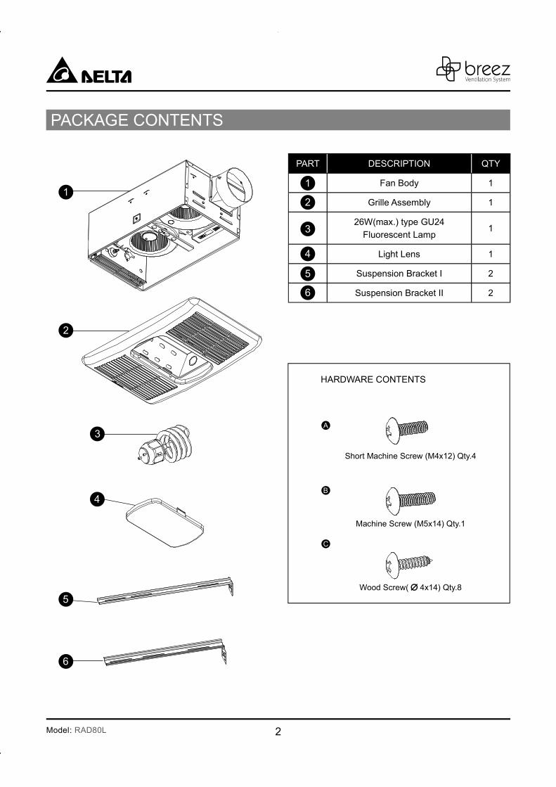
PART DESCRIPTION QTY
Fan Body 1
Grille Assembly 1
26W(max.) type GU24
Fluorescent Lamp1
Light Lens 1
Suspension Bracket I 2
Suspension Bracket II 2
PACKAGE CONTENTS
A
B
C
HARDWARE CONTENTS
Wood Screw( 4x14) Qty.8
Short Machine Screw (M4x12) Qty.4
Machine Screw (M5x14) Qty.1
1
2
3
4
5
6
3 Model: RAD80L
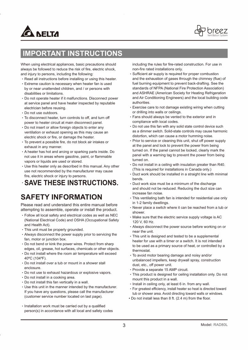
When using electrical appliances, basic precautions should
and injury to persons, including the following:Read all instructions before installing or using this heater.Extreme caution is necessary when heater fan is used by or near unattended children, and / or persons with disabilities or limitations. Do not operate heater if it malfunctions. Disconnect power at service panel and have heater inspected by reputable electrician before reusing.Do not use outdoors.To disconnect heater, turn controls to off, and turn off power to heater circuit at main disconnect panel.Do not insert or allow foreign objects to enter any ventilation or exhaust opening as this may cause an
exhaust in any manner. A heater has hot and arcing or sparking parts inside. Do
vapors or liquids are used or stored. Use this heater only as described in this manual. Any other use not recommended by the manufacturer may cause
SAVE THESE INSTRUCTIONS. SAFETY INFORMATION Please read and understand this entire manual before attempting to assemble, operate or install the product.
Follow all local safety and electrical codes as well as NEC (National Electrical Code) and OSHA (Occupational Safety and Health Act).This unit must be properly grounded.Always disconnect the power supply prior to servicing the fan, motor or junction box.Do not bend or kink the power wires. Protect from sharp edges, oil, grease, hot surfaces, chemicals or other objects.Do not install where the room air temperature will exceed 40ºC (104ºF).Do not install over a tub or mount in a shower stall enclosure.Do not use to exhaust hazardous or explosive vapors.Do not install in a cooking area.Do not install this fan vertically in a wall.Use this unit in the manner intended by the manufacturer. If you have any questions, please call the manufacturer (customer service number located on last page).
person(s) in accordance with all local and safety codes
fuel burning equipment to prevent back-drafting. See the standards of NFPA (National Fire Protection Association) and ASHRAE (American Society for Heating Refrigeration and Air Conditioning Engineers) and the local building code authorities.Exercise care to not damage existing wiring when cutting or drilling into walls or ceilings.Fans should always be vented to the exterior and in compliance with local codes.Do not use this fan with any solid state control device such as a dimmer switch. Solid-state controls may cause harmonic distortion, which can cause a motor humming noise.Prior to service or cleaning this unit, shut off power supply at the panel and lock to prevent the power from being turned on. If the panel cannot be locked, clearly mark the panel with a warning tag to prevent the power from being turned on.Do not install in a ceiling with insulation greater than R40. (This is required for installations in Canada only.)Duct work should be installed in a straight line with minimal bends.Duct work size must be a minimum of the discharge and should not be reduced. Reducing the duct size can increase fan noise.This ventilating bath fan is intended for residential use only in 1-2 family dwellings.Never place a switch where it can be reached from a tub or shower.Make sure that the electric service supply voltage is AC 120 V, 60 Hz.Always disconnect the power source before working on or near the unit.This unit is designed and tested to be a supplemental heater for use with a timer or a switch. It is not intended to be used as a primary source of heat, or controlled by a thermostat.To avoid motor bearing damage and noisy and/or unbalanced impellers, keep drywall spray, construction dust, etc., off power unit.Provide a separate 15 AMP circuit.This product is designed for ceiling installation only. Do not mount this product in a wall.Install in ceiling only, at least 6 in. from any wall.
tub or shower area. Avoid directing toward walls or windows.
IMPORTANT INSTRUCTIONS

4Model: RAD80L
PREPARATION
Tools Required for Assembly (not included): Hammer, Flathead Screwdriver, Wire Nuts, Nails, Duct Tape,
Phillips Head Screwdriver, Utility Knife
Helpful Tools (not included): Electric Drill, Drill Bits
WARNING: Turn off electricity at breaker box before beginning installation.
Before installation, provide inspection and future maintenance access at a location that will not interfere with installation work.
You may need the help of a second person to install this fan: one person on the attic side and one on the room side.
Remove ceiling section using dimensions provided below. Be careful to cut hole exactly. If hole is too big, the fan
grille will not hide it.
Determine the distance between your joists.
DIMENSION REQUIREMENTS
WARNING
Ceiling Opening (L)
Ceiling Opening (W)
Ceiling Opening (H)
14 in. 8 in. 5 in.
Housing Dimension (L)
Housing Dimension (W)
Housing Dimension (H)
14 in. 8 in. 5 in.
Proper insulation around the fan to minimize building heat loss and gain.
Locate unit away from heating or cooling sources.
the shortest possible duct run and minimum number of elbows will be needed.Use a roof cap or wall cap that has a built-in damper to reduce backdrafts.
Spacing A on center joists
16.0 inches
19.2 inches
24.0 inches
Note: Installations may vary depending on how the previous bath fan was installed. Supplies necessary for the installation of your bath fan are not all included. However, most are available at your local home improvement or
hardware store.
Be careful to cut hole exactly. If the hole is too big, the fan grille will not hide it.
Do not install over a tub or mount in a shower stall enclosure.
External timer/dimmer switch can be used. Pleasecontact Delta Breez customer service and consult with a licensed electrician for compatibility.
3/ 4 1/ 2
1/ 2 3/ 8
1/ 4 1/ 2
l
l
l
l
ll
l
l l
l
l
5 Model: RAD80L
Carefully remove unit from carton. Remove the foam in the housing. Refer to the Package Contents list on page 2
to verify that all parts are present.
Installing the fan body in an existing building requires an accessible area (attic or crawl space) above the planned installation location and existing duct and wiring.
Check area above installation location to ensure that:
• Wiring can be run to the planned location. • No wiring or other obstructions can interfere with installation.
•
heater.
6Model: RAD80L
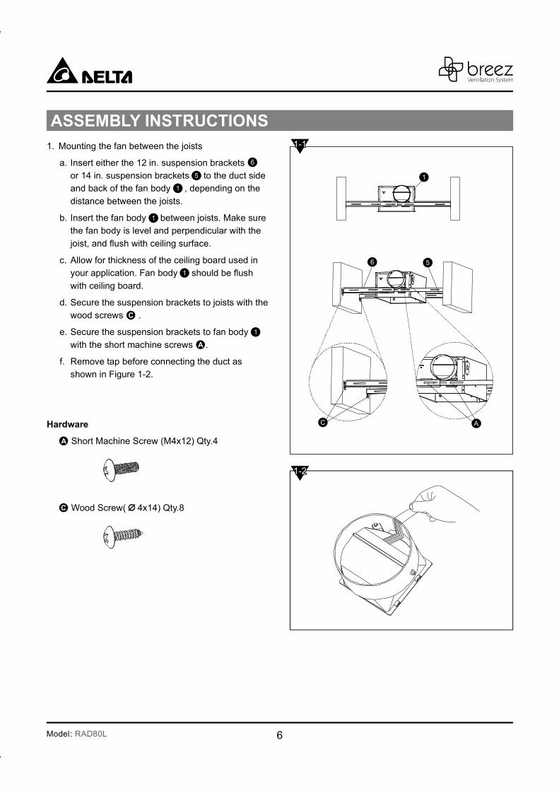
1. Mounting the fan between the joists
a. Insert either the 12 in. suspension brackets
or 14 in. suspension brackets to the duct side and back of the fan body , depending on the
distance between the joists.
b. Insert the fan body between joists. Make sure the fan body is level and perpendicular with the
c. Allow for thickness of the ceiling board used in your application. Fan body
with ceiling board.
d. Secure the suspension brackets to joists with the wood screws .
e. Secure the suspension brackets to fan body
with the short machine screws .
f. Remove tap before connecting the duct as shown in Figure 1-2.
Short Machine Screw (M4x12) Qty.4
Wood Screw( 4x14) Qty.8
56
AC
1
1-2
1-1
6
5
1
1
1
1
7 Model: RAD80L
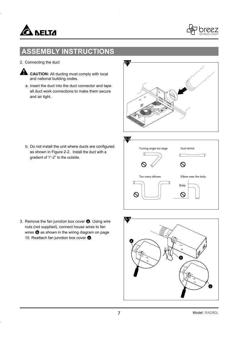
2. Connecting the duct
All ducting must comply with local and national building codes.
a. Insert the duct into the duct connector and tape
all duct work connections to make them secure and air tight.
b. as shown in Figure 2-2. Install the duct with a
gradient of 1°-2° to the outside.
3. Remove the fan junction box cover . Using wire nuts (not supplied), connect house wires to fan
wires as shown in the wiring diagram on page 10. Reattach fan junction box cover .
Turning angle too large Duct shrink
Too many elbows Elbow near the body
Body
a
c
b
2-1
2-2
3-1

8Model: RAD80L
4. Completing the Installation
a. Check the plug from the fan into the receptacle
marked “Vent”
Check the plug from the heating unit into the receptacle marked “Heat”
b. Plug the Light Connector into the receptacle
marked “Light”
c. Install the Grille Assembly into the Fan
Body using the Machine Screw .
Do not use Wood Screw in place of
Machine Screw .
Vent
Light
Heat
Wood screw ( 4x14) Machine screw (M5x14)
4-1
4-2
4-3
9 Model: RAD80L
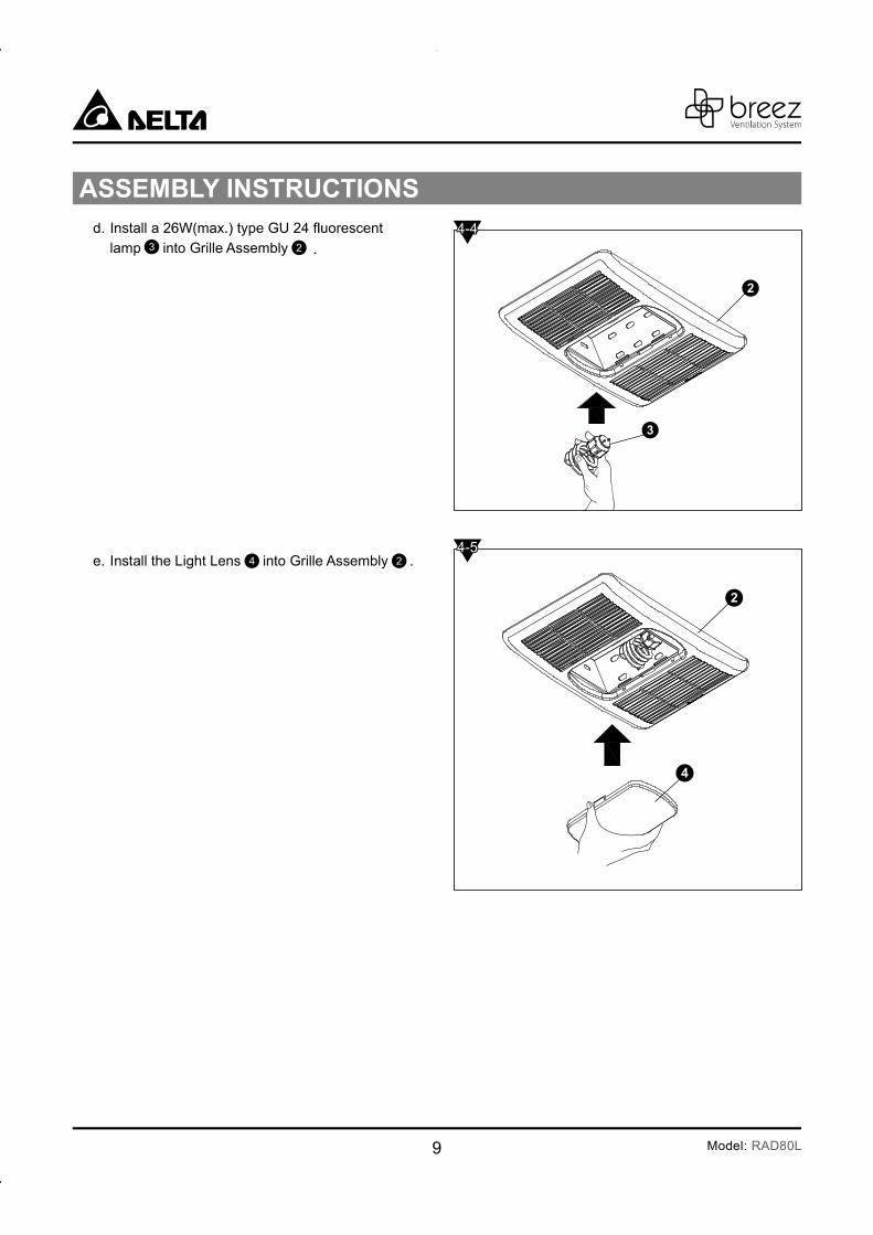
d.
lamp into Grille Assembly .
e. Install the Light Lens into Grille Assembly .
4-4
4-5
3 2
4 2
10Model: RAD80L
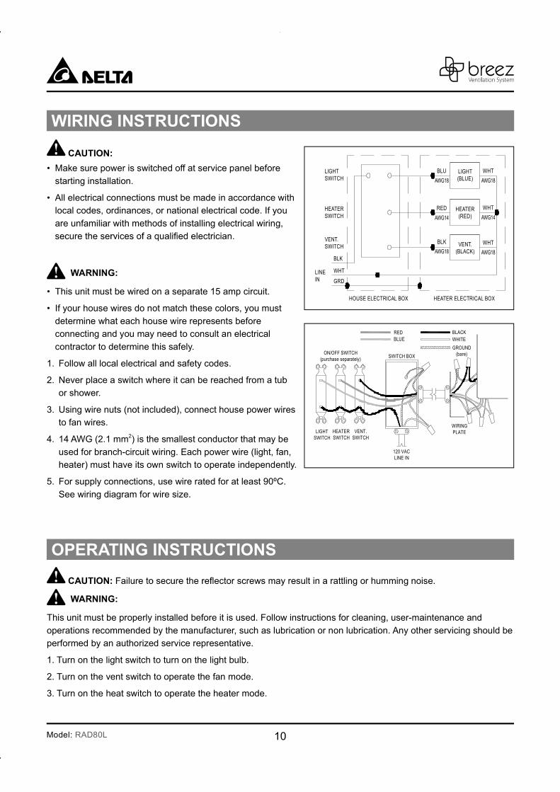
WIRING INSTRUCTIONS
OPERATING INSTRUCTIONS
CAUTION:
Make sure power is switched off at service panel before
starting installation.
All electrical connections must be made in accordance with local codes, ordinances, or national electrical code. If you
are unfamiliar with methods of installing electrical wiring,
WARNING:
This unit must be wired on a separate 15 amp circuit.
If your house wires do not match these colors, you must
determine what each house wire represents before
connecting and you may need to consult an electrical
contractor to determine this safely.
1. Follow all local electrical and safety codes.
2. Never place a switch where it can be reached from a tub
or shower.
3. Using wire nuts (not included), connect house power wires to fan wires.
4. 14 AWG (2.1 mm2) is the smallest conductor that may be
used for branch-circuit wiring. Each power wire (light, fan, heater) must have its own switch to operate independently.
5. For supply connections, use wire rated for at least 90ºC.
See wiring diagram for wire size.
CAUTION: ng or humming noise.
WARNING:
This unit must be properly installed before it is used. Follow instructions for cleaning, user-maintenance and
operations recommended by the manufacturer, such as lubrication or non lubrication. Any other servicing should be performed by an authorized service representative.
1. Turn on the light switch to turn on the light bulb.
2. Turn on the vent switch to operate the fan mode.
3. Turn on the heat switch to operate the heater mode.
LIGHTSWITCH
LIGHT(BLUE)
WHT
AWG18
BLU
AWG18
RED
AWG14
BLK
AWG18
WHT
AWG18
WHT
AWG14
HEATER(RED)
VENT.(BLACK)
HEATERSWITCH
VENT.SWITCH
LINEIN
HOUSE ELECTRICAL BOX HEATER ELECTRICAL BOX
BLK
WHT
GRD
BLACK
ON/OFF SWITCH(purchase separately)
SWITCH BOX
120 VACLINE IN
WHITE
GROUND(bare)
VENT.SWITCH
WIRINGPLATEHEATER
SWITCHLIGHT
SWITCH
BLUERED
11 Model: RAD80L
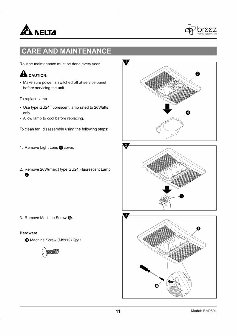
1. Remove Light Lens cover.
2. Remove 26W(max.) type GU24 Fluorescent Lamp
.
3. Remove Machine Screw .
Machine Screw (M5x12) Qty.1
Routine maintenance must be done every year.
• Make sure power is switched off at service panel
before servicing the unit.
To replace lamp
•
only.• Allow lamp to cool before replacing.
To clean fan, disassemble using the following steps:
1
2
3
4
3
12Model: RAD80L
Vacuumcleaner
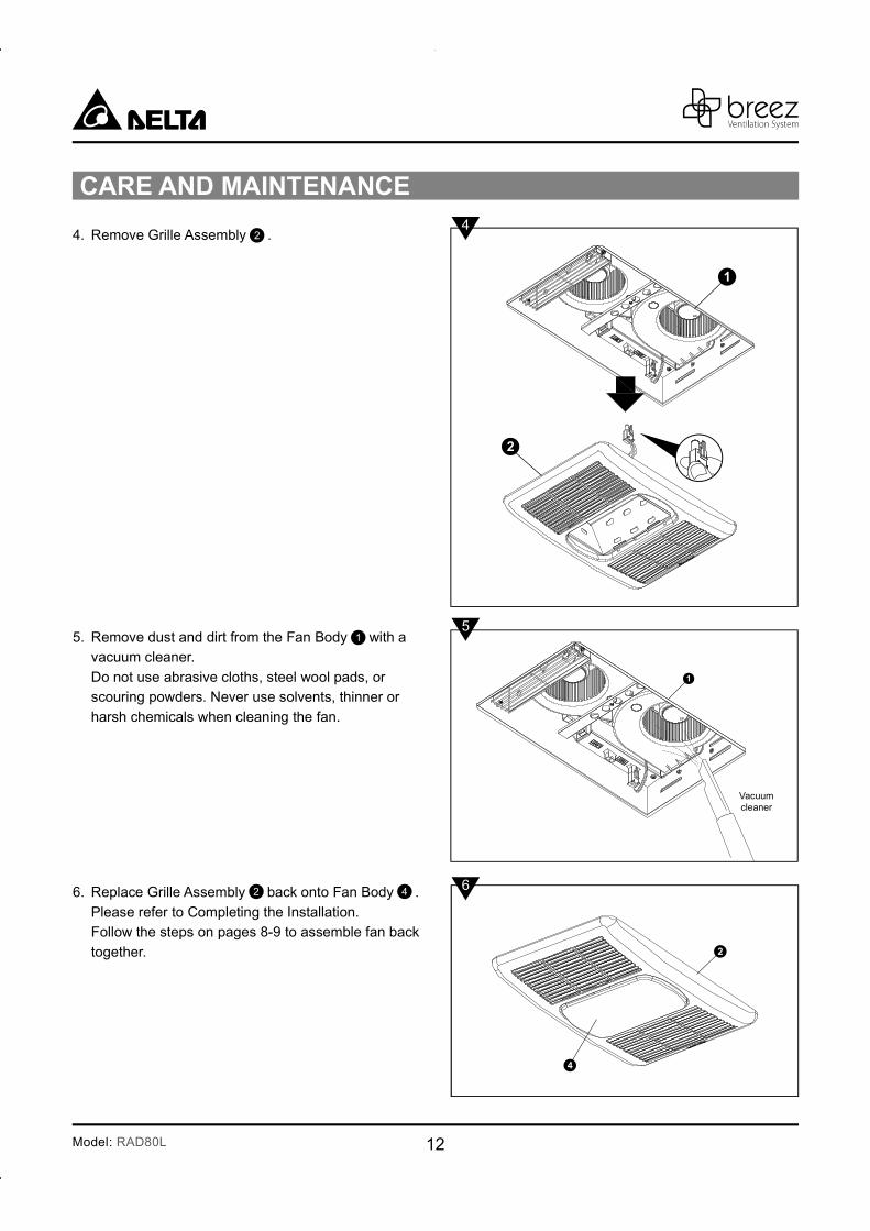
4. Remove Grille Assembly .
5. Remove dust and dirt from the Fan Body with a vacuum cleaner.
Do not use abrasive cloths, steel wool pads, or
scouring powders. Never use solvents, thinner or
harsh chemicals when cleaning the fan.
6. Replace Grille Assembly back onto Fan Body .
Please refer to Completing the Installation. Follow the steps on pages 8-9 to assemble fan back
together.
4
5
6
1
2 4
2
13 Model: RAD80L
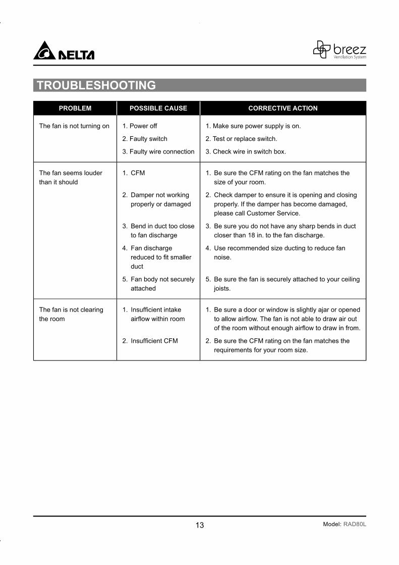
The fan is not turning on 1. Power off
2. Faulty switch
3. Faulty wire connection
1. Make sure power supply is on.
2. Test or replace switch.
3. Check wire in switch box.
The fan seems louder
than it should
1. CFM
2. Damper not working
properly or damaged
3. Bend in duct too close to fan discharge
4. Fan discharge
duct
5. Fan body not securely
attached
1. Be sure the CFM rating on the fan matches the
size of your room.
2. Check damper to ensure it is opening and closing
properly. If the damper has become damaged, please call Customer Service.
3. Be sure you do not have any sharp bends in duct closer than 18 in. to the fan discharge.
4. Use recommended size ducting to reduce fan noise.
5. Be sure the fan is securely attached to your ceiling
joists.
The fan is not clearing
the room
1.
2.
1. Be sure a door or window is slightly ajar or opened
2. Be sure the CFM rating on the fan matches the requirements for your room size.
14Model: RAD80L
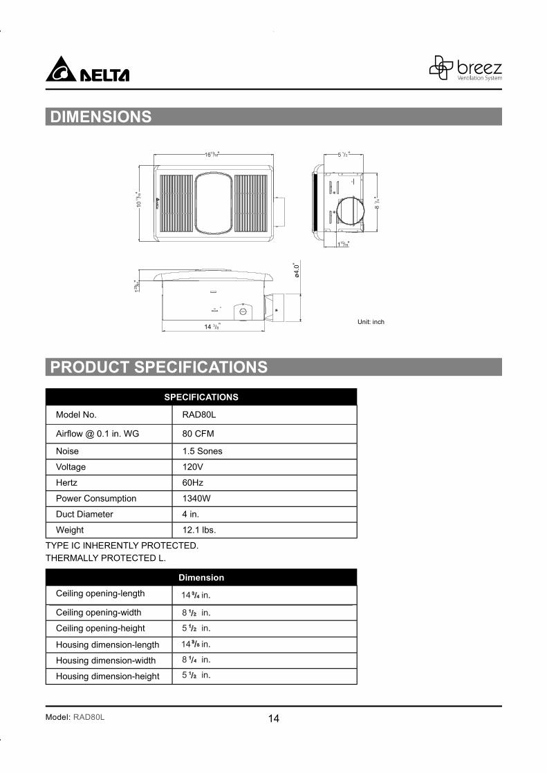
DIMENSIONS
14Unit: inch
ø4.
0
PRODUCT SPECIFICATIONS
SPECIFICATIONS
Model No. RAD80L
80 CFM
Noise 1.5 Sones
Voltage 120V
Hertz 60Hz
Power Consumption 1340W
Duct Diameter 4 in.
Weight 12.1 lbs.
TYPE IC INHERENTLY PROTECTED. THERMALLY PROTECTED L.
Dimension
Ceiling opening-length
Ceiling opening-width
Ceiling opening-height
Housing dimension-length
Housing dimension-width
Housing dimension-height
15 Model: RAD80L
DELTA ELECTRONICS THREE YEAR LIMITED WARRANTY
Delta Electronics Inc. (“Delta Electronics”) warrants to the original consumer purchaser in the USA that the Breez
ventilation fan products will be free from defects in material or workmanship. This warranty is limited to three (3)
years from the original date of purchase.
Limitations and Exclusions
1. During the warranty period, a replacement for any defective product will be supplied free of charge for installation
by the consumer. The warranty provided herein does not cover charges for labor or other costs incurred in the troubleshooting, repair, removal, and installation service.
2. All returns of defective parts or products must include the product model number, and must be made through an authorized Delta Electronics distributor. Authorized returns must be shipped prepaid. Repaired or replacement
products will be shipped by Delta Electronics F.O.B. shipping point.
3. Delta Electronics shall not be liable for any indirect, incidental, consequential, punitive, or special damages
arising out of or in connection with products use or performance, regardless of the form of action whether in contract, tort (including negligence), strict product liability or otherwise.
4.
5. The warranty does not cover if user does not comply with manufacturer’s installation manual.
6. To qualify for warranty service, you must notify Delta Electronics at the address or telephone number below.
7. Delta Electronics shall have no liability to the original owner-user with respect to any defect caused by abuse,
misuse, neglect, improper transportation or storage, improper testing, improper installation, improper operation,
accident of products or parts thereof, or unusual deterioration or degradation of products or parts thereof due to
US Toll Free Number: 1-888-979-9889
Address: 46101 Fremont Boulevard, Fremont, CA 94538

16Model: RAD80L