Embed Size (px)
Citation preview
7/18/2019 Ventilation Guide
http://slidepdf.com/reader/full/ventilation-guide 1/223
Heating/Piping/AirConditioningeating Piping irConditioning
ENGINEERINGN IN RIN
VENTILATION GUIDE FOR
AUTOMOTIVE INDUSTRY
Machining Processes
Body Shops Assembly Plants
Paint Shops & Areas
1st Edition 2 0 0 0
Published by:
7/18/2019 Ventilation Guide
http://slidepdf.com/reader/full/ventilation-guide 2/223
VENTILATION GUIDEFOR AUTOMOTIVE INDUSTRY
1st Edition
Prepared by the International Task Force
Chairman: Alexander M. Zhivov, Ph.D., P.E.
Published by:
Heating/Piping/Air Conditioning EngineeringPenton Media, Inc.Penton Media Bldg.
1300 E. 9th StreetCleveland, OH 44114-1503
© 2000 Zhivov & Associates, L.L.C., Champaign, IL
7/18/2019 Ventilation Guide
http://slidepdf.com/reader/full/ventilation-guide 3/223
1. INTRODUCTION
Ventilation Guide for Automotive Industry (Guide) is the result of practical experiences by the members ofthe International Task Force and a compilation from different sources of information from around theworld (regulations, standards, books and technical papers, examples of good and bad practices fromdifferent consulting and auto manufacturing companies). The Guide follows the design procedureadopted by the group of international experts for the serial of Applications in Industrial Ventilation DesignGuidebook (DGB, 2000). The Guide is not intended to become a law, standard or to replace any ofexisting international, national, industry or company standards, manuals or guidelines. With the dynamic
developments of production processes in auto manufacturing industry, there is an essential need tomatch manufacturing and construction processes and schedules with an appropriate approaches inventilation systems designs and the state-of-the-art ventilation technologies. The experts participating indevelopment of this Guide view it as a document containing a summary of essential information,facilitating better understanding and communication between facilities and process engineers, consultantsand HVAC systems manufacturers providing services to the automotive industry. The technologiesdescribed in the Guide shall be applied with consideration of specific climatic conditions and geographicallocation, national regulations, building designs and auto manufacturing company priorities and internalpolicies. The international Task Force members nor collectively or individually assume any responsibilityfor any inadvertent misinformation, or for the results in the use of this document.
INTERNATIONAL TASK FORCE
The document was prepared by the International Task Force:Michael Busch - Ford Motor Co. (Germany) [Chapter 6]
Larry Cinat - BEI Associates, Inc. (USA) [Chapter 4]
Goran Danielsson - ABB Contracting AB (Sweden) [Chapters 10,11]
Bruce Davis - Deere and Co. (USA) [Chapters 5,9]
James Dolfi - Ford Motor Co. (USA) [Chapter 5]
Roy Durgan - Monsanto EnviroChem Co. (USA) [Chapter 6]
William Edens - SSOE (USA) [Chapter 6]
Piero Gauna - FIAT Engineering (Italy) [Chapter 4]
Wolfgang Hera - DaimlerChrysler AG (Germany) [Chapters 4,9]
William Johnston – Ford Motor Co. (USA) [Chapter 6]
Dick Kvarnström - Scania Partner AB (Sweden) [Chapters 4,9]
Wayne Lawton - Giffels Associates, Inc. (USA) [Chapters 5,6,12]
Kenneth Lennartsson - Lindab AB (Sweden) [Chapter 12]
Mike Lepage - RWDI, Inc. (Canada) [Chapter 14]
Gunnar Lindeström - Plymovent AB (Sweden) [Chapter 5,7]
Wayne Lutz - Plymovent Corp. (USA) [Chapters 6,7]
Jerker Lycke - ABB Contracting AB (Sweden) [Chapters 9,10,11]
ReviewersSten-Arne Hakanson - Celero Support AB (Sweden)
G.A. (Bill) Navas - SMACNA (USA) [Chapter 12]
Karl Pontenius - Scania Partner AB (Sweden)
Clive Nixon – Fenwal (USA) [Chapter 5]
Manfred Pack - Ford (Germany) [Chapters 3,4,9,11]
Gary Pashaian - Monroe Environmental Corp. [Chapter 6]
John Richards - SH&G, Inc. (USA) [Chapter 8]
Adolf Rymkevich – Acad. of Refrigeration and Food Technology
(Russia) [Chapters 9,11]
Florian Sack - AUDI AG (Germany) [Chapters 5]
Jurgen Schneider- DaimlerChrysler AG (Germany) [Chapters 4,9]
Eugene Shilkrot - Termec (Russia) [Chapter 10]
Hasse Spetz - Celero Support AB, Volvo Group (Sweden) [Chapter
4,5,11]
Mathew Vondrasek - Haden, Inc. (USA) [Chapter 8]
Bede Wellford - Airxchange, Inc. (USA) [Chapter 11]
Daniel White - General Motors Corp. (USA) [Chapter 6]
Alfred Woody - Giffels Associates, Inc. (USA) [Chapters 3,4,6,7,9]
Alexander Zhivov - Zhivov & Associates, L.L.C. (USA) - Task Force
Chair [Chapters 1 through 13]
Bill Heitbrink - NIOSH (USA) [Chapter 5]
Milad (Chris) Wakim - Ford Motor Co. (USA)
Alfred Woody – Albert Kahn Associates, Inc. (USA)
The development of this Guide would not be possible without funding from ABB Contracting AB, CeleroSupport AB, DaimlerChrysler AG, Ford Motor Company, Lindab AB, Plymovent AB, ScaniaPartners AB and Zhivov & Associates, L.L.C.
Special thanks to the following companies which contributed to development of the Guide by sharing their
information and providing examples of HVAC technology used in auto manufacturing facilities: ABBContracting (Sweden), Audi (Germany), Bentler Industries (U.S.A.), BMW (Austria, Germany),DaimlerChrysler (Brazil, Germany, U.S.A.), Deer & Company (U.S.A.), EHC Technik (Sweden), FordMotor Company (Brazil, Germany, UK, U.S.A.), FIAT Engineering (Italy), General Motors (U.S.A.),Jacob Handte & Co. (Germany), Krantz-TKT (Germany), Lindab (Sweden), Monroe Environmental(U.S.A.), Plymovent (Sweden), Renault (France), Scania Partner (Sweden), Subaru-IsuzuAutomotive (U.S.A.), Toyota Motor Manufacturing (U.S.A.), Unipart Yashiyo Technology (UK),Vauxhall Motors Ltd. (UK), Volkswagen (Germany), Volvo Cars (Belgium, Sweden), Volvo Trucks(Sweden).
Many helpful criticism of early drafts was received from participants of four International Conferences and
Workshops, which took place in Boken_ s (Sweden, 1998), Detroit (U.S.A., 1999), S_u Paulo (Brazil,
2000) and in Aachen (Germany, 2000).

7/18/2019 Ventilation Guide
http://slidepdf.com/reader/full/ventilation-guide 4/223
2. DOCUMENT SCOPE
The Guide introduces the reader to various types of ventilation systems, including general supply and
exhaust and local exhaust, for control of contaminants and to maintain thermal comfort in production halls
with processes specific to automotive industry, principles of system design and selection, and drawings
that illustrate ventilation techniques. Also, this document contains or refers to information on production
processes, contaminants found in production processes and their sources and process related measures
allowing the emission rates reduction.
With the understanding that automotive production has a few specific processes (e.g., welding on
assembly lines, engine testing and maneuvering at the end of assembly line, car body painting, etc.) and
a numerous processes similar to those found in other industries, the Guide contains only the information
primarily related to specific processes and refers to the information that is available from other sources.
TABLE OF CONTENT
1. Introduction
2. Document Scope
3. Design methodology
4. Design Criteria
4.1. Meteorological data
4.2. Indoor air temperature and velocity
4.3. Supply and exhaust air rates
4.4. Indoor air quality
4.5. Air distribution method selection
4.6. HVAC equipment selection
4.7. References
5. Body shop and component manufacturing shops with welding and joining operations
5.1. Process description.
5.2. Types of contaminants.
5.3. Target Levels
5.4. Process related measures allowing the emission rates reduction.
5.5. Ventilation
5.5.1. Principles of Ventilation
5.5.2. Local Exhaust Ventilation
5.5.3. General Ventilation
5.5.4. Fume Filtration
5.5.5. Fire and explosion protection for exhaust systems5.5.6. Explosion protection with aluminum grinding and polishing operations
5.6. References
Appendix 5.1. Fume Generation Data
Appendix 5.2. Fume Constituent Concentration Data
Appendix 5.3. Fume Generated per amount of Electrode Used
7/18/2019 Ventilation Guide
http://slidepdf.com/reader/full/ventilation-guide 5/223
6. Machining processes
6.1. Process description
6.2. Contaminant emission
6.3. Target levels
6.4. Measures to reduce occupational exposure to metalworking fluids
6.3.1. Coolant selection
6.3.2. Considerations for the Design of Machine Enclosures for Airborne
Contaminants Control
6.5. Ventilation
6.5.1. Principles of Ventilation.
6.5.2. Process and Local Exhaust Ventilation
6.5.3. Re-circulation
6.5.4. General Ventilation
6.5.5. Oil mist separation
6.6. References.
Appendix 1. Machine types.
Appendix 2. Enclosures
Appendix 3. Approximate airflow rates to be extracted from machinesAppendix 4. Coolant types.
7. Assembly line
7.1. Process description
7.2. Process emissions overview
7.3. Sources of auto emissions
7.4. Target levels
7.5 Process related measures to reduce occupational exposure to vehicle exhausts and fuel
vapors.
7.6 Ventilation
7.6.1. Local exhaust systems.
7.6.2. General supply ventilation7.6.3. General exhaust systems
7.6.4. Exhausted air filtration and recirculation.
7.7. References
8. Paint shops and areas
8.1. Process description.
8.2 Qualitative analysis of major loads and emissions from paint process
8.3. Coordination of the HVAC and process engineers
8.4. Heat emission to the building
8.5. Target level
8.6. Ventilation
8.6.1. Coordination between process and building ventilation.8.6.2. General supply systems
8.6.3. General exhaust systems
8.6.4. Air distribution
8.7. References

7/18/2019 Ventilation Guide
http://slidepdf.com/reader/full/ventilation-guide 6/223
9. General Ventilation Systems
9.1. Types of general ventilation systems
9.2. General supply systems
9.3. General exhaust systems
9.4. Centralized and decentralized (modular) systems
9.5. Constant air volume (CAV) and variable air volume (VAV) systems
9.6. Air handling unit
9.7. Working environment heating and cooling
9.7.1. Heating systems
9.7.2. Cooling systems
9.8. References
10. Quantity and methods of air supply
10.1 Quantity of supply air
10.2. Air supply methods
10.4. Selection and design
10.5. Typical practices of air supply into auto manufacturing facilities
10.5.1. Machining shops10.5.2. Body shops and other shops with welding operations
10.5.3. Assembly shops
10.5.4. Paint shops
10.6. References
11. Return (recirculation) air and energy recovery from exhaust air
11.1. Outside and recirculating air flow
11.2. Requirements to the recirculating air cleanliness
11.3. Energy recovery
11.4 References
12. Special requirements to duct selection and design
12.1 General considerations 12.2. Special requirements to ducts used for metalworking fluids (MWF) collection systems.
12.3. References
13. Methods of building protection from warm/cold air drafts through gates and other
apertures
14. Outdoor air pollution prevention
7/18/2019 Ventilation Guide
http://slidepdf.com/reader/full/ventilation-guide 7/223
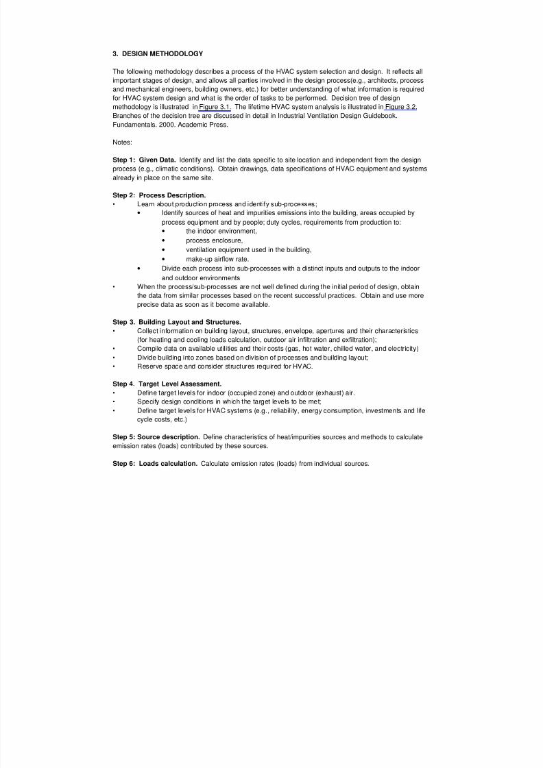
3. DESIGN METHODOLOGY
The following methodology describes a process of the HVAC system selection and design. It reflects all
important stages of design, and allows all parties involved in the design process(e.g., architects, process
and mechanical engineers, building owners, etc.) for better understanding of what information is required
for HVAC system design and what is the order of tasks to be performed. Decision tree of design
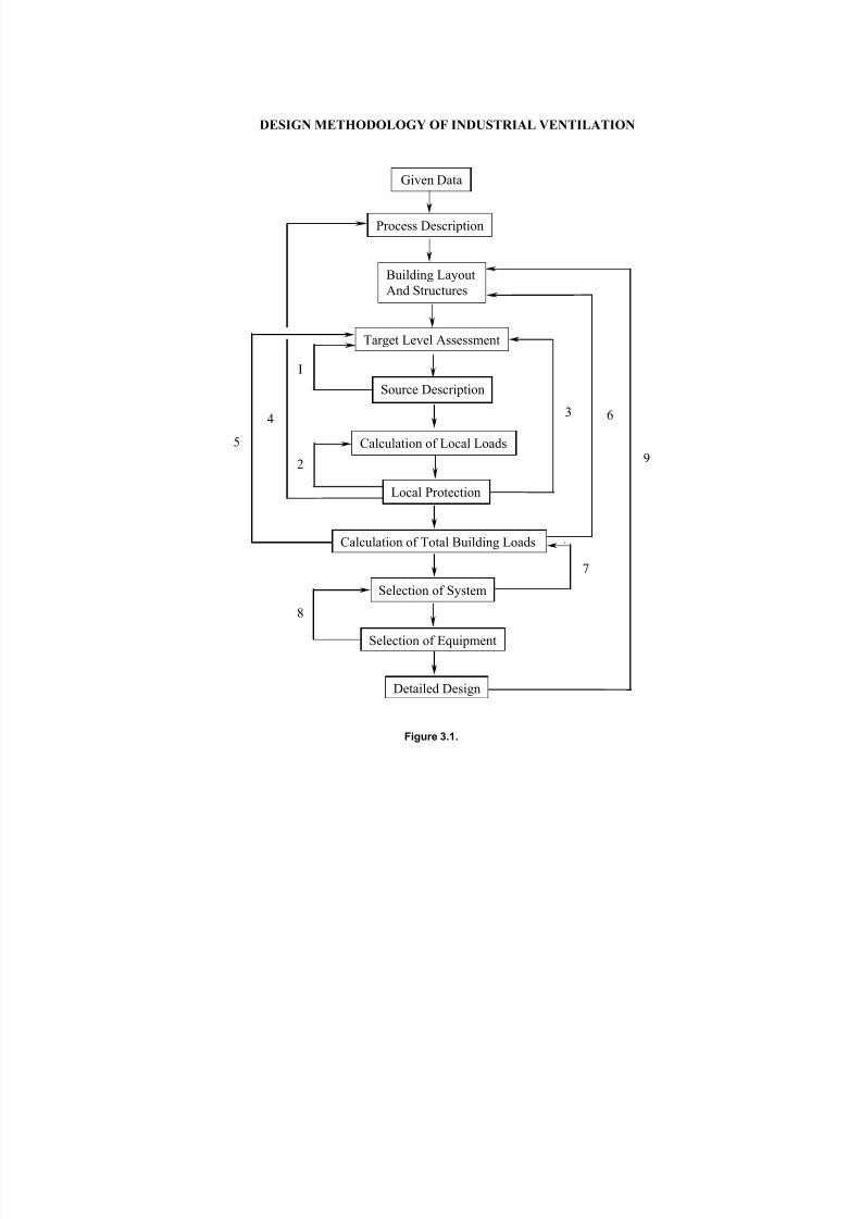
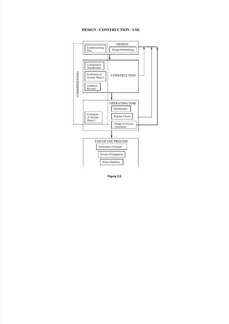
methodology is illustrated in Figure 3.1. The lifetime HVAC system analysis is illustrated in Figure 3.2.
Branches of the decision tree are discussed in detail in Industrial Ventilation Design Guidebook.
Fundamentals. 2000. Academic Press.
Notes:
Step 1: Given Data. Identify and list the data specific to site location and independent from the design
process (e.g., climatic conditions). Obtain drawings, data specifications of HVAC equipment and systems
already in place on the same site.
Step 2: Process Description.
• Learn about production process and identify sub-processes;• Identify sources of heat and impurities emissions into the building, areas occupied by
process equipment and by people; duty cycles, requirements from production to:
• the indoor environment,
• process enclosure,
• ventilation equipment used in the building,
• make-up airflow rate.
• Divide each process into sub-processes with a distinct inputs and outputs to the indoor
and outdoor environments
• When the process/sub-processes are not well defined during the initial period of design, obtain
the data from similar processes based on the recent successful practices. Obtain and use more
precise data as soon as it become available.
Step 3. Building Layout and Structures.
• Collect information on building layout, structures, envelope, apertures and their characteristics
(for heating and cooling loads calculation, outdoor air infiltration and exfiltration);
• Compile data on available utilities and their costs (gas, hot water, chilled water, and electricity)
• Divide building into zones based on division of processes and building layout;
• Reserve space and consider structures required for HVAC.
Step 4. Target Level Assessment.
• Define target levels for indoor (occupied zone) and outdoor (exhaust) air.
• Specify design conditions in which the target levels to be met;
• Define target levels for HVAC systems (e.g., reliability, energy consumption, investments and life
cycle costs, etc.)
Step 5: Source description. Define characteristics of heat/impurities sources and methods to calculate
emission rates (loads) contributed by these sources.
Step 6: Loads calculation. Calculate emission rates (loads) from individual sources.
7/18/2019 Ventilation Guide
http://slidepdf.com/reader/full/ventilation-guide 8/223
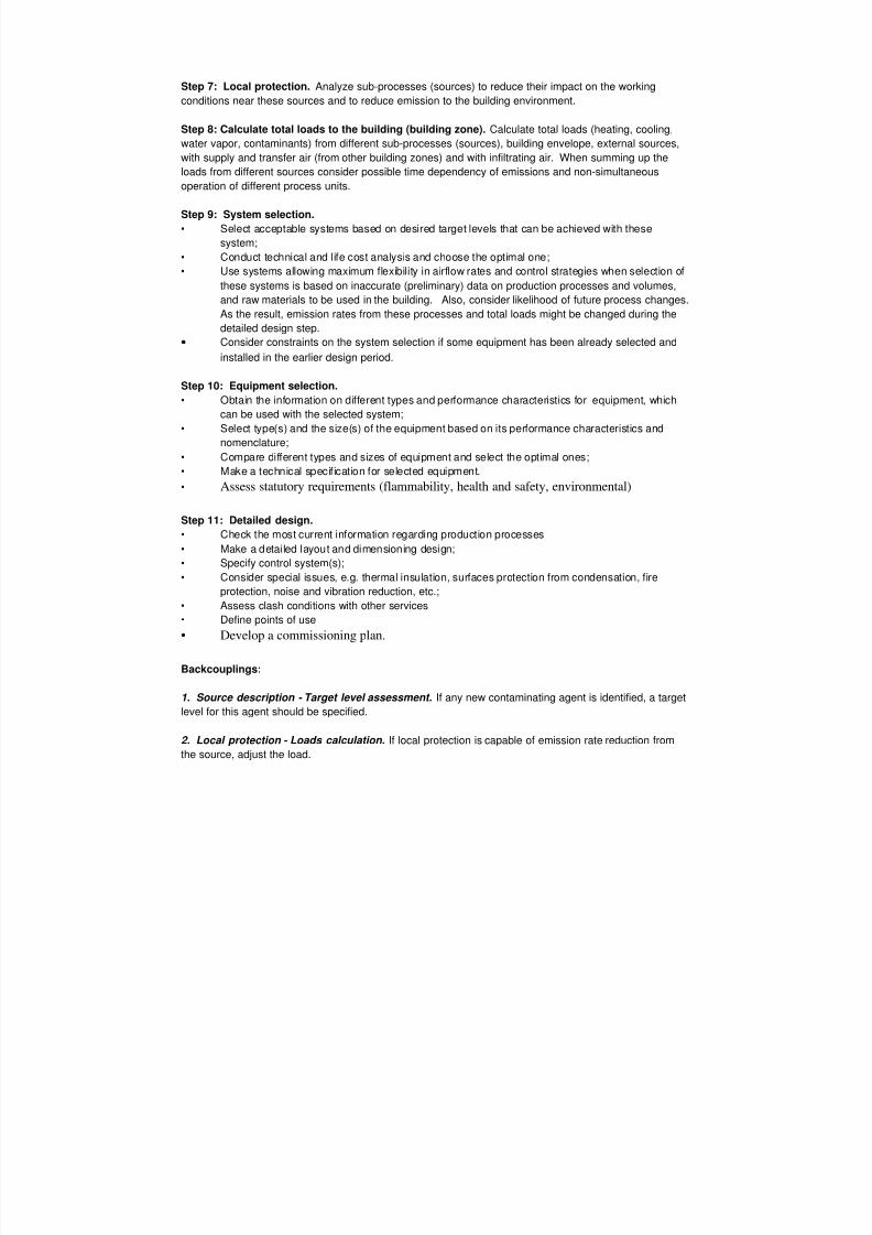
Step 7: Local protection. Analyze sub-processes (sources) to reduce their impact on the working
conditions near these sources and to reduce emission to the building environment.
Step 8: Calculate total loads to the building (building zone). Calculate total loads (heating, cooling,
water vapor, contaminants) from different sub-processes (sources), building envelope, external sources,
with supply and transfer air (from other building zones) and with infiltrating air. When summing up the
loads from different sources consider possible time dependency of emissions and non-simultaneous
operation of different process units.
Step 9: System selection.
• Select acceptable systems based on desired target levels that can be achieved with these
system;
• Conduct technical and life cost analysis and choose the optimal one;
• Use systems allowing maximum flexibility in airflow rates and control strategies when selection of
these systems is based on inaccurate (preliminary) data on production processes and volumes,
and raw materials to be used in the building. Also, consider likelihood of future process changes.
As the result, emission rates from these processes and total loads might be changed during the
detailed design step.• Consider constraints on the system selection if some equipment has been already selected and
installed in the earlier design period.
Step 10: Equipment selection.
• Obtain the information on different types and performance characteristics for equipment, which
can be used with the selected system;
• Select type(s) and the size(s) of the equipment based on its performance characteristics and
nomenclature;
• Compare different types and sizes of equipment and select the optimal ones;
• Make a technical specification for selected equipment.
• Assess statutory requirements (flammability, health and safety, environmental)
Step 11: Detailed design.
• Check the most current information regarding production processes
• Make a detailed layout and dimensioning design;
• Specify control system(s);
• Consider special issues, e.g. thermal insulation, surfaces protection from condensation, fire
protection, noise and vibration reduction, etc.;
• Assess clash conditions with other services
• Define points of use
• Develop a commissioning plan.
Backcouplings:
1. Source description - Target level assessment. If any new contaminating agent is identified, a target
level for this agent should be specified.
2. Local protection - Loads calculation. If local protection is capable of emission rate reduction from
the source, adjust the load.
7/18/2019 Ventilation Guide
http://slidepdf.com/reader/full/ventilation-guide 9/223
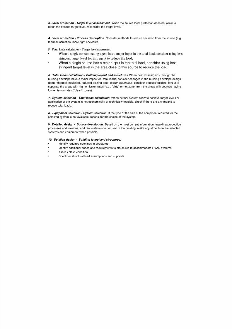
3. Local protection - Target level assessment . When the source local protection does not allow to
reach the desired target level, reconsider the target level.
4. Local protection - Process description. Consider methods to reduce emission from the source (e.g.,
thermal insulation, more tight enclosure)
5. Total loads calculation - Target level assessment.
• When a single contaminating agent has a major input in the total load, consider using less
stringent target level for this agent to reduce the load;
• When a single source has a major input in the total load, consider using less
stringent target level in the area close to this source to reduce the load.
6. Total loads calculation - Building layout and structures. When heat losses/gains through the
building envelope have a major impact on total loads, consider changes in the building envelope design
(better thermal insulation, reduced glazing area, etc) or orientation ; consider process/building layout to
separate the areas with high emission rates (e.g., "dirty" or hot zone) from the areas with sources having
low emission rates ("clean" zones).
7. System selection - Total loads calculation. When neither system allow to achieve target levels or
application of the system is not economically or technically feasible, check if there are any means to
reduce total loads.
8. Equipment selection - System selection. If the type or the size of the equipment required for the
selected system is not available, reconsider the choice of the system.
9. Detailed design - Source description. Based on the most current information regarding production
processes and volumes, and raw materials to be used in the building, make adjustments to the selected
systems and equipment when possible.
10. Detailed design - Building layout and structures.
• Identify required openings in structures
• Identify additional space and requirements to structures to accommodate HVAC systems.
• Assess clash condition
• Check for structural load assumptions and supports
7/18/2019 Ventilation Guide
http://slidepdf.com/reader/full/ventilation-guide 10/223
DESIGN METHODOLOGY OF INDUSTRIAL VENTILATION
Given Data
Process Description
Building Layout
And Structures
Target Level Assessment
Source Description
Calculation of Local Loads
Local Protection
Calculation of Total Building Loads
Selection of System
Selection of Equipment
Detailed Design
2
34
5
6
9
7
8
I
Figure 3.1.
7/18/2019 Ventilation Guide
http://slidepdf.com/reader/full/ventilation-guide 11/223
DESIGN - CONSTRUCTION - USE
DESIGNCommissioningPlan Design Methodology
CONSTRUCTION
ConstructionMana ement
Evaluation of
System, Phase I
UpdatingRecords
OPERATING TIME
Evaluationof System,
Phase 2
Maintenance
Regular Checks
Change in Process-Assesment
END OF THE PROCESS
Demolition of System
Re-use of Equipment
Waste Handling
C O M M I S S I O N I N G
Figure 3.2.

7/18/2019 Ventilation Guide
http://slidepdf.com/reader/full/ventilation-guide 12/223
4. DESIGN CRITERIA
4.1. Meteorological data. As the design conditions for outdoor air temperature, humidity and wind use
the following information, which can be obtained from the National Climate Centers, WHO World Data
Center or for the USA, Canadian and many international locations from ASHRAE Handbook [4]:
• Summer (cooling system design) - 1.0% Design Climatic Conditions;
• Winter (heating system design) - 99.0% Design Climatic Conditions.
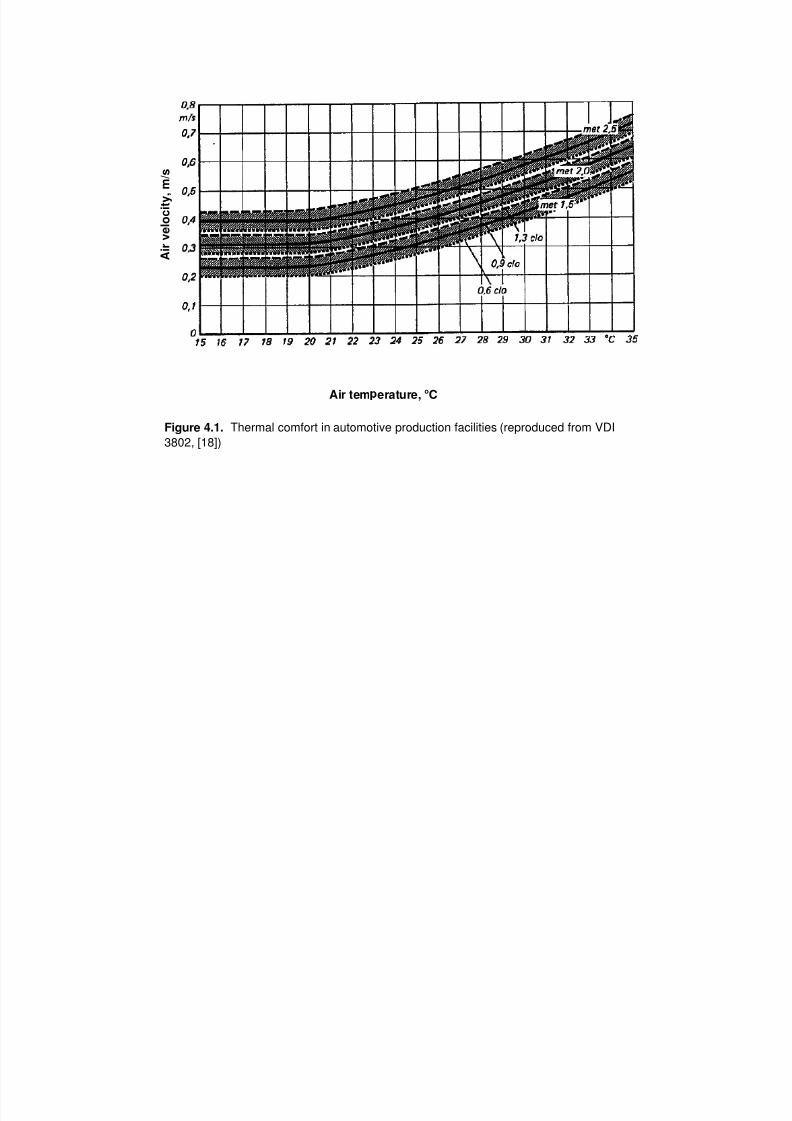
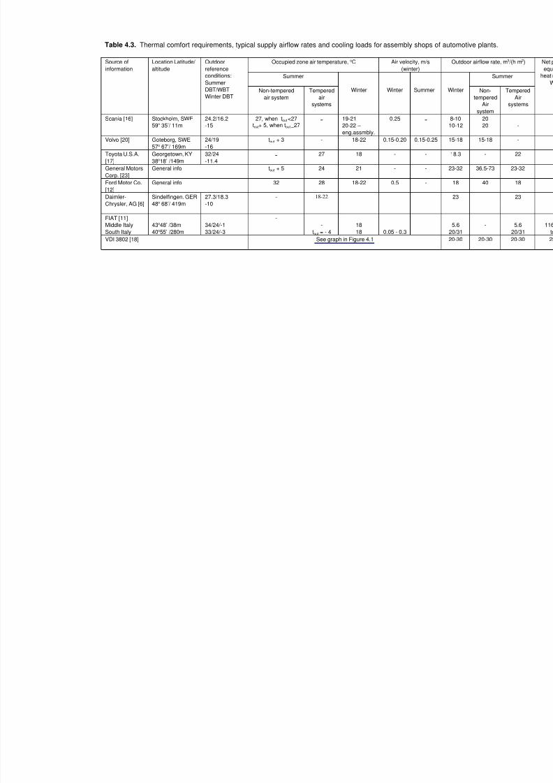
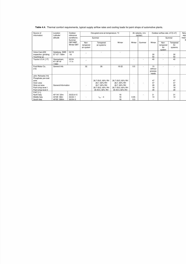
4.2 Indoor air temperature and velocity. Examples of current practices in different auto manufacturing
companies for selected shops are listed in Tables 4.1. - 4.4. The data for these Tables is compelled from
company technical specifications, technical publications, and through private communications.
4.3. Supply and exhausted air rates. Calculations shall be performed to determine cooling and heating
loads, contaminant emission rates, air flow rates for building pressurization, air flows to compensate air
exhausted by process equipment and local exhausts. For supply air rates refer to Chapter 10. Air flow
rates exhausted by process equipment obtain from process engineers. Airflow rates exhausted from
process equipment enclosures and by local exhausts refer to corresponding sections of Chapters 5, 6, 7
and 8. For more detailed information on local exhaust design see ACGIH [1], ASHRAE Handbook [5]andDGB [8]. Outdoor supply airflow rates and cooling loads for production shops in Tables 4.1. - 4.4. are
listed only for preliminary consideration. New general and local supply and exhaust systems shall be
designed and equipped with control systems to maintain required airflow balance and building pressure at
all foreseeable systems operation modes. Consult building and process engineers to obtain drawings
and data specifications for all HVAC equipment and systems already in place on the same site or planned
to be installed in the future.
4.4. Indoor air quality. For contaminant exposure limits refer to national regulatory documents (e.g.,
OSHA [2], ACGIH [2] for U.S.A., AFS [3] for Sweden, TRGS 900 [2] for Germany, GOST [9,15] for
Russia). Industry and individual company policies on exposure limits are typically substantially lower. For
the latest data, contact manufacturer industrial hygienists. Current (1998) and proposed exposure limits
for contaminants related to processes discussed in the Guide are summarized in corresponding sectionsof Chapters 5, 6, 7 and 8.
4.5. Air distribution method selection. Air distribution method should be selected and designed such
that air diffusers and duct system does not conflict with the production process. Air distribution shall allow
to achieve the required thermal conditions in the occupied zone with a highest possible heat and
contaminant removal effectiveness and the lowest life-cycle costs. For information on air distribution
method selection and design refer to Chapter 11, ASHRAE Handbook [4] and DGB [8].
4.6. HVAC equipment selection. Specified materials and equipment shall comply with the applicable
ISO, CEN, Europvent, and ANSI standards and under provision of National laws, standards and
regulations, relating to the country of installation. Consult with auto manufacturer about existing company
requirements and criteria. HVAC equipment shall be designed and equipped with all safety and operating
controls required to meet the Insurance Underwriters' approval.
7/18/2019 Ventilation Guide
http://slidepdf.com/reader/full/ventilation-guide 13/223
Figure 4.1. Thermal comfort in automotive production facilities (reproduced from VDI
3802, [18])
A i r v e l o c i t y , m / s
Air tem erature, oC
7/18/2019 Ventilation Guide
http://slidepdf.com/reader/full/ventilation-guide 14/223
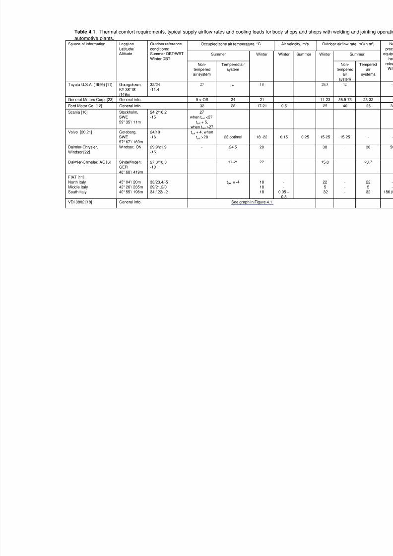
Table 4.1. Thermal comfort requirements, typical supply airflow rates and cooling loads for body shops and shops with
automotive plants.Occupied zone air temperature, oC Air velocity, m/s Out
Summer
Source of information Location
Latitude/
Altitude
Outdoor reference
conditions:
Summer DBT/WBT
Winter DBT
Non-
tempered
air system
Tempered air
system
Winter Winter Summer Winte
Toyota U.S.A. (1999) [17] Georgetown,
KY 38o18’
/149m
32/24
-11.4
27 - 18 29.3
General Motors Corp. [23] General info. 5 > OS 24 21 11-23
Ford Motor Co. [12] General info. 32 28 17-21 0.5 25
Scania [16] Stockholm,
SWE
59o 35’/ 11m
24.2/16.2
-15
27
when tout <27
tout + 5,
when tout >27
Volvo [20,21] Goteborg,
SWE
57o 67’/ 169m
24/19
-16
tout + 4, when
tout >28 23 optimal 18 -22 0.15 0.25 15-25
Daimler-Chrysler,
Windsor [22]
Windsor, ON 29.9/21.9
-15
- 24.5 20 38
Daimler-Chrysler, AG [6] Sindelfingen.
GER
48o 68’/ 419m
27.3/18.3
-10
17-21 ?? 15.8
FIAT [11]
North Italy
Middle Italy
South Italy
45o 04’/ 20m
42o 26’/ 235m
40o 55’/ 196m
33/23.4/-5
29/21.2/0
34 / 22/ -2
tout = -4 18
18
18
-
-
0.05 –
0.3
22
5
32
VDI 3802 [18] General info. See graph in Figure 4.1
7/18/2019 Ventilation Guide
http://slidepdf.com/reader/full/ventilation-guide 15/223
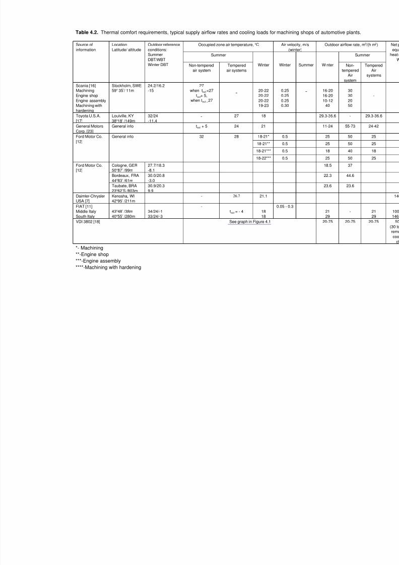
Table 4.2. Thermal comfort requirements, typical supply airflow rates and cooling loads for machining shops of automo
Occupied zone air temperature, oC Air velocity, m/s
(winter)
Outd
Summer
Source of
information
Location
Latitude/ altitude
Outdoor reference
conditions:
Summer
DBT/WBT
Winter DBT Non-tempered
air system
Tempered
air systems
Winter Winter Summer Winter
Scania [16]
Machining
Engine shop
Engine assembly
Machining with
hardening
Stockholm, SWE
59o 35’/ 11m
24.2/16.2
-15
27
when tout <27
tout+ 5,when tout _27
-20-22
20-22
20-22
19-23
0.25
0.25
0.25
0.30
- 16-20
16-20
10-12
40
Toyota U.S.A.
[17]
Louiville, KY
38o18’ /149m
32/24
-11.4- 27 18 29.3-36.
General Motors
Corp. [23]
General info tout + 5 24 21 11-24
18-21* 0.5 25
18-21** 0.5 25
18-21*** 0.5 18
Ford Motor Co.
[12]
General info 32 28
18-22*** 0.5 25
Cologne, GER
50o87’ /99m
27.7/18.3
-8.1
18.5
Bordeaux, FRA
44o83’ /61m
30.0/20.8
-3.0
22.3
Ford Motor Co.
[12]
Taubate, BRA
23o62’S /803m
30.9/20.3
9.9
23.6
Daimler-Chrysler
USA [7]
Kenosha, WI
42o95’ /211m
- 26.7 21.1
FIAT [11]
Middle Italy
South Italy
43o48’ /38m
40o55’ /280m
34/24/-1
33/24/-3
-
tout = - 4 18
18
0.05 - 0.3
21
29
VDI 3802 [18] See graph in Figure 4.1 20-75
*- Machining
**-Engine shop
***-Engine assembly
****-Machining with hardening
7/18/2019 Ventilation Guide
http://slidepdf.com/reader/full/ventilation-guide 16/223
Table 4.3. Thermal comfort requirements, typical supply airflow rates and cooling loads for assembly shops of automo
Occupied zone air temperature, oC Air velocity, m/s
(winter)
Outd
Summer
Source of
information
Location Latitude/
altitude
Outdoor
reference
conditions:
Summer
DBT/WBT
Winter DBTNon-tempered
air system
Tempered
air
systems
Winter Winter Summer Winte
Scania [16] Stockholm, SWE
59o 35’/ 11m
24.2/16.2
-15
27, when tout <27tout+ 5, when tout _27
- 19-21
20-22 –
eng.assmbly.
0.25 - 8-10
10-12
Volvo [20] Goteborg, SWE
57o 67’/ 169m
24/19
-16
tout + 3 - 18-22 0.15-0.20 0.15-0.25 15-18
Toyota U.S.A.
[17]
Georgetown, KY
38o18’ /149m
32/24
-11.4- 27 18 - - 18.3
General Motors
Corp. [23]
General info tout + 5 24 21 - - 23-32
Ford Motor Co.
[12]
General info 32 28 18-22 0.5 - 18
Daimler-
Chrysler, AG [6]
Sindelfingen. GER
48o 68’/ 419m
27.3/18.3
-10
- 18-22 23
FIAT [11]
Middle Italy
South Italy
43o48’ /38m
40o55’ /280m
34/24/-1
33/24/-3
-
-
tout = - 4
18
18 0.05 - 0.3
5.6
20/31
VDI 3802 [18] See graph in Figure 4.1 20-30
7/18/2019 Ventilation Guide
http://slidepdf.com/reader/full/ventilation-guide 17/223
Table 4.4. Thermal comfort requirements, typical supply airflow rates and cooling loads for paint shops of automotive p
Occupied zone air temperature, oC Air velocity, m/s
(winter)
Outd
Summer
Source of
information
Location
Latitude/ altitude
Outdoor
referenceconditions:
Summer
DBT/WBT
Winter DBTNon-
tempered
air system
Tempered
air systems
Winter Winter Summer Winte
Volvo Cars [20]
Inspection, grinding
Touching-up
Goteborg, SWE
57o 67’/ 169m
24/19
-16 - - -
30
50
Toyota U.S.A. [17] Georgetown,
KY 38o18’
/149m
32/24
-11.4 - - - 40
Ford Motor Co.
[12]
General info 32 26 18-22 0.5 - 15
withou
procesneeds
John Richards [14]
Phosphate pre-coat
area
Oven area
Strip out area
Paint shop level 1
Paint shop level 2
General Information -
26.7-29.5, 60% RH
26.7, 60% RH
26.7, 60% RH
26.7-29.5, 60% RH
35-40.5, 60% RH
26.7-29.5, 60% RH
26.7, 60% RH
26.7, 60% RH
26.7-29.5, 60% RH
35-40.5, 60% RH
- -
47
47
28
18
28
FIAT [11]
North Italy
Middle Italy
South Italy
45o 04’/ 20m
43o48’ /38m
40o55’ /280m
33/23.4/-5
34/24/-1
33/24/-3
- tout - 4
18
18
18
0.05 -
0.3
- 31
10
-

7/18/2019 Ventilation Guide
http://slidepdf.com/reader/full/ventilation-guide 18/223
4.7. References
1. ACGIH. 1998. Industrial Ventilation. A Manual of Recommended Practice. 23 edition. American
Conference of Government Industrial Hygienists. Cincinnati, OH.
2. ACGIH. 1998. Guide to Occupational Exposure Values – 1998. American Conference of
Governmental Industrial Hygienists. Cincinnati, OH.
3. AFS 1996:2. 1996. Occupational Exposure Limit Values. The Swedish National Board of Occupational
Safety and Health.
4. ASHRAE. 1997. ASHRAE Handbook. Fundamentals. American Society of Heating,
Refrigerating and Air-Conditioning Engineers. Atlanta, GA.
5. ASHRAE. 1999. ASHRAE Handbook. HVAC Applications. American Society of Heating,
Refrigerating and Air-Conditioning Engineers. Atlanta, GA.
6. DaimlerChrysler AG. 1999. DaimlerChrysler Werk, Sindelfingen. Private communications with
Mr. Wolfgang Hera and Mr. J_rgen Schneider.
7. DaimlerChrysler. 1999. Kenosha Engine Plant. Private communications with Mr. Dave Mattox.
8. DGB. 2000. Industrial Ventilation Design Guidebook. Fundamentals. Academic Press.
9. GOST. 1988. GOST 12.1.005-88. General Requirements to the Occupied Zone Air. Moscow:
GOSSTANDART.10. GM. 1997. Facilities Common Systems’ CD. General Motors Corporation. Worldwide Facilities
Group.
11. FIAT Engineering. 1999. Air Systems Solutions for air-conditioning in automotive production
buildings. Private communications with Mr. Piero Gauna and Mr. Donato Leo. Turin, October
1999.
12. Ford. 2000. Ford Motor Land Services, Koeln-Niehl. Private communications with Mr. Manfred
Pack.
13. Holness, Gordon. 1998. World-Class Facilities, World-Class Timing.
14. Richards, John. 2000. Paint shop building ventilating and air conditioning. Proceedings of the 4th
International Conference “Ventilation for Automotive Industry”. June 19-21. Aachen, Germany.
15. SanPiN. 1996. SanPiN 2.2.4.548096. Hygiene requirements to microclimate in production halls.
Moscow: Russia Ministry of Health.16. Scania Partner AB. 1997. Private communications with Mr. Karl Pontenius.
17. Toyota. 1999. Toyota Motor Manufacturing, U.S.A., Inc. Private communications with Mr. Charles
Martin.
18. VDI 3802. 1997. Air Conditioning Systems for Factories. VDI – Richtlinien. D_sseldorf: VDI.
19. VDI 2262. 1994. Workplace Air . Reduction of Exposure to Air Pollutants. Ventilation Technical
Measures. Part 3. D_sseldorf: VDI.
20. Volvo. 1998. Celero Support AB. Private communications with Mr. Sten-Arne H_ kansson.
21. Volvo. 1997. Technical Specifications. HVAC systems for production halls. G_teborg 1997-09-
01.
22. Williams, Steven. 1999. Plant ventilation with a ductless air supply – DaimlerChrysler Toledo
Assembly Plant. Part 3. HVAC system analysis and design. Proceedings of the 2 nd International
Conference and Workshop “Ventilation for Automotive Industry”. April 18-21. Detroit, MI.23. Woody, Alfred. 1998. Ventilation Systems Applied to Automotive Manufacturing. Proceedings of
the 1st International Conference and Workshop “Ventilation for Automotive Industry”. September
7-9. Boken_ s, Sweden.
7/18/2019 Ventilation Guide
http://slidepdf.com/reader/full/ventilation-guide 19/223
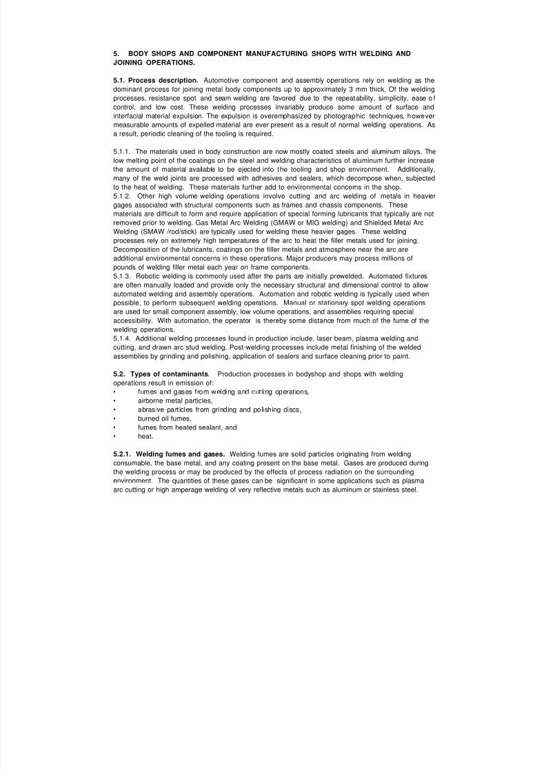
5. BODY SHOPS AND COMPONENT MANUFACTURING SHOPS WITH WELDING AND
JOINING OPERATIONS.
5.1. Process description. Automotive component and assembly operations rely on welding as the
dominant process for joining metal body components up to approximately 3 mm thick. Of the welding
processes, resistance spot and seam welding are favored due to the repeatability, simplicity, ease o f
control, and low cost. These welding processes invariably produce some amount of surface and
interfacial material expulsion. The expulsion is overemphasized by photographic techniques, however
measurable amounts of expelled material are ever present as a result of normal welding operations. As
a result, periodic cleaning of the tooling is required.
5.1.1. The materials used in body construction are now mostly coated steels and aluminum alloys. The
low melting point of the coatings on the steel and welding characteristics of aluminum further increase
the amount of material available to be ejected into the tooling and shop environment. Additionally,
many of the weld joints are processed with adhesives and sealers, which decompose when, subjected
to the heat of welding. These materials further add to environmental concerns in the shop.
5.1.2. Other high volume welding operations involve cutting and arc welding of metals in heavier
gages associated with structural components such as frames and chassis components. These
materials are difficult to form and require application of special forming lubricants that typically are not
removed prior to welding. Gas Metal Arc Welding (GMAW or MIG welding) and Shielded Metal Arc
Welding (SMAW /rod/stick) are typically used for welding these heavier gages. These welding
processes rely on extremely high temperatures of the arc to heat the filler metals used for joining.
Decomposition of the lubricants, coatings on the filler metals and atmosphere near the arc are
additional environmental concerns in these operations. Major producers may process millions of
pounds of welding filler metal each year on frame components.
5.1.3. Robotic welding is commonly used after the parts are initially prewelded. Automated fixtures
are often manually loaded and provide only the necessary structural and dimensional control to allow
automated welding and assembly operations. Automation and robotic welding is typically used when
possible, to perform subsequent welding operations. Manual or stationary spot welding operations
are used for small component assembly, low volume operations, and assemblies requiring specialaccessibility. With automation, the operator is thereby some distance from much of the fume of the
welding operations.
5.1.4. Additional welding processes found in production include, laser beam, plasma welding and
cutting, and drawn arc stud welding. Post-welding processes include metal finishing of the welded
assemblies by grinding and polishing, application of sealers and surface cleaning prior to paint.
5.2. Types of contaminants. Production processes in bodyshop and shops with welding
operations result in emission of:
• fumes and gases from welding and cutting operations,
• airborne metal particles,
• abrasive particles from grinding and polishing discs,
• burned oil fumes,• fumes from heated sealant, and
• heat.
5.2.1. Welding fumes and gases. Welding fumes are solid particles originating from welding
consumable, the base metal, and any coating present on the base metal. Gases are produced during
the welding process or may be produced by the effects of process radiation on the surrounding
environment. The quantities of these gases can be significant in some applications such as plasma
arc cutting or high amperage welding of very reflective metals such as aluminum or stainless steel.
7/18/2019 Ventilation Guide
http://slidepdf.com/reader/full/ventilation-guide 20/223
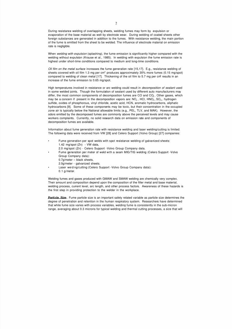
2
During resistance welding of overlapping sheets, welding fumes may form by expulsion or
evaporation of the base material as well by electrode wear. During welding of coated sheets other
foreign substances are generated in addition to the fumes. With resistance welding, the main portion
of the fume is emitted from the sheet to be welded. The influence of electrode material on emission
rate is negligible.
When welding with expulsion (splashing), the fume emission is significantly higher compared with the
welding without expulsion (Krause et al., 1985). In welding with expulsion the fume emission rate is
highest under short-time conditions compared to medium and long-time conditions.
Oil film on the metal surface increases the fume generation rate [15,17]. E.g., resistance welding of
sheets covered with oil film 1.3 mg per cm2 produces approximately 30% more fumes (0.15 mg/spot)
compared to welding of clean metal [17]. Thickening of the oil film to 5.7 mg per cm2 results in an
increase of the fume emission to 0.65 mg/spot.
High temperatures involved in resistance or arc welding could result in decomposition of sealant usedin some welded joints. Though the formulation of sealant used by different auto manufacturers may
differ, the most common components of decomposition fumes are CO and CO2 . Other gases, which
may be a concern if present in the decomposition vapors are: NOx , HCl, HNO3 , SO2 , hydrogen
sulfide, oxides of phosphorous, vinyl chloride, acetic acid, HCN, aromatic hydrocarbons, aliphatic
hydrocarbons [9]. Some of these components may be toxic, but their concentration in the occupied
zone air is typically below the National allowable limits (e.g., PEL, TLV, and MAK). However, the
odors emitted by the decomposed fumes are commonly above the perceived levels and may cause
workers complaints. Currently, no solid research data on emission rate and components of
decomposition fumes are available.
Information about fume generation rate with resistance welding and laser welding/cutting is limited.
The following data were received from VW [28] and Celero Support (Volvo Group) [27] companies:
• Fume generation per spot welds with spot resistance welding of galvanized sheets:
1.42 mg/spot (Zn) - VW data,
2.0 mg/spot (Zn) - Celero Support -Volvo Group Company data.
• Fume generation per meter of weld with a seam MIG/TIG welding (Celero Support -Volvo
Group Company data):
0.7g/meter – black sheets,
2.0g/meter - galvanized sheets.
• Laser welding/cutting (Celero Support -Volvo Group Company data):
0.1 g/meter.
Welding fumes and gases produced with GMAW and SMAW welding are chemically very complex.Their amount and composition depend upon the composition of the filler metal and base material,
welding process, current level, arc length, and other process factors. Awareness of these hazards is
the first step in providing protection to the welder in the workplace.
Particle Size . Fume particle size is an important safety related variable as particle size determines the
degree of penetration and retention in the human respiratory system. Researchers have determined
that while fume size varies with process variables, welding fume is consistently in the sub-micron
range, averaging about 0.3 microns for typical welding and thermal cutting processes, a size that will
7/18/2019 Ventilation Guide
http://slidepdf.com/reader/full/ventilation-guide 21/223
3
easily penetrate the respiratory system. It should also be noted that these fine particles tend to
agglomerate or form larger clusters, which can be retained in the lungs.
Specific Contaminants . Data on specific contaminant emissions produced by various welding
processes are usually available from electrode manufacturers (MSDS sheets).
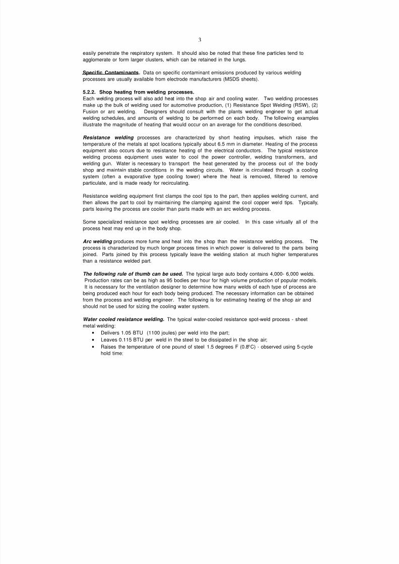
5.2.2. Shop heating from welding processes.
Each welding process will also add heat into the shop air and cooling water. Two welding processes
make up the bulk of welding used for automotive production, (1) Resistance Spot Welding (RSW), (2)
Fusion or arc welding. Designers should consult with the plants welding engineer to get actual
welding schedules, and amounts of welding to be performed on each body. The following examples
illustrate the magnitude of heating that would occur on an average for the conditions described.
Resistance welding processes are characterized by short heating impulses, which raise the
temperature of the metals at spot locations typically about 6.5 mm in diameter. Heating of the process
equipment also occurs due to resistance heating of the electrical conductors. The typical resistancewelding process equipment uses water to cool the power controller, welding transformers, and
welding gun. Water is necessary to transport the heat generated by the process out of the body
shop and maintain stable conditions in the welding circuits. Water is circulated through a cooling
system (often a evaporative type cooling tower) where the heat is removed, filtered to remove
particulate, and is made ready for recirculating.
Resistance welding equipment first clamps the cool tips to the part, then applies welding current, and
then allows the part to cool by maintaining the clamping against the cool copper weld tips. Typically,
parts leaving the process are cooler than parts made with an arc welding process.
Some specialized resistance spot welding processes are air cooled. In this case virtually all of the
process heat may end up in the body shop.
Arc welding produces more fume and heat into the shop than the resistance welding process. The
process is characterized by much longer process times in which power is delivered to the parts being
joined. Parts joined by this process typically leave the welding station at much higher temperatures
than a resistance welded part.
The following rule of thumb can be used. The typical large auto body contains 4,000- 6,000 welds.
Production rates can be as high as 95 bodies per hour for high volume production of popular models.
It is necessary for the ventilation designer to determine how many welds of each type of process are
being produced each hour for each body being produced. The necessary information can be obtained
from the process and welding engineer. The following is for estimating heating of the shop air and
should not be used for sizing the cooling water system.
Water cooled resistance welding. The typical water-cooled resistance spot-weld process - sheet
metal welding:
• Delivers 1.05 BTU (1100 joules) per weld into the part;
• Leaves 0.115 BTU per weld in the steel to be dissipated in the shop air;
• Raises the temperature of one pound of steel 1.5 degrees F (0.8oC) - observed using 5-cycle
hold time;
7/18/2019 Ventilation Guide
http://slidepdf.com/reader/full/ventilation-guide 22/223
4
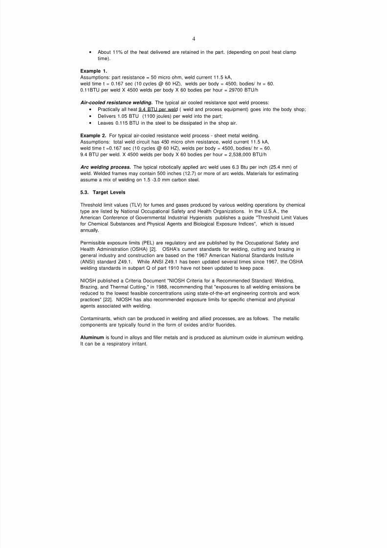
• About 11% of the heat delivered are retained in the part. (depending on post heat clamp
time).
Example 1.
Assumptions: part resistance = 50 micro ohm, weld current 11.5 kA,
weld time t = 0.167 sec (10 cycles @ 60 HZ), welds per body = 4500, bodies/ hr = 60.
0.11BTU per weld X 4500 welds per body X 60 bodies per hour = 29700 BTU/h
Air-cooled resistance welding. The typical air cooled resistance spot weld process:
• Practically all heat 9.4 BTU per weld ( weld and process equipment) goes into the body shop;
• Delivers 1.05 BTU (1100 joules) per weld into the part;
• Leaves 0.115 BTU in the steel to be dissipated in the shop air.
Example 2. For typical air-cooled resistance weld process - sheet metal welding.
Assumptions: total weld circuit has 450 micro ohm resistance, weld current 11.5 kA,
weld time t =0.167 sec (10 cycles @ 60 HZ), welds per body = 4500, bodies/ hr = 60.9.4 BTU per weld. X 4500 welds per body X 60 bodies per hour = 2,538,000 BTU/h
Arc welding process. The typical robotically applied arc weld uses 6.3 Btu per inch (25.4 mm) of
weld. Welded frames may contain 500 inches (12.7) or more of arc welds. Materials for estimating
assume a mix of welding on 1.5 -3.0 mm carbon steel.
5.3. Target Levels
Threshold limit values (TLV) for fumes and gases produced by various welding operations by chemical
type are listed by National Occupational Safety and Health Organizations. In the U.S.A., the
American Conference of Governmental Industrial Hygienists publishes a guide "Threshold Limit Values
for Chemical Substances and Physical Agents and Biological Exposure Indices", which is issuedannually.
Permissible exposure limits (PEL) are regulatory and are published by the Occupational Safety and
Health Administration (OSHA) [2]. OSHA's current standards for welding, cutting and brazing in
general industry and construction are based on the 1967 American National Standards Institute
(ANSI) standard Z49.1. While ANSI Z49.1 has been updated several times since 1967, the OSHA
welding standards in subpart Q of part 1910 have not been updated to keep pace.
NIOSH published a Criteria Document "NIOSH Criteria for a Recommended Standard: Welding,
Brazing, and Thermal Cutting," in 1988, recommending that "exposures to all welding emissions be
reduced to the lowest feasible concentrations using state-of-the-art engineering controls and work
practices" [22]. NIOSH has also recommended exposure limits for specific chemical and physical
agents associated with welding.
Contaminants, which can be produced in welding and allied processes, are as follows. The metallic
components are typically found in the form of oxides and/or fluorides.
Aluminum is found in alloys and filler metals and is produced as aluminum oxide in aluminum welding.
It can be a respiratory irritant.
7/18/2019 Ventilation Guide
http://slidepdf.com/reader/full/ventilation-guide 23/223
5
Barium may be found in some self-shielded flux-cored electrodes. Exposure to soluble barium
compounds can cause irritation of the eyes, nose, throat and skin.
Cadmium occurs as a plating material or brazing alloy. It can be a serious hazard resulting in
emphysema, kidney damage and pulmonary edema.
Carbon Monoxide in low concentrations results from the reaction of carbon dioxide and the welding
arc in GMAW and FCAW welding. Symptoms include headaches, dizziness and mental confusion.
Chromium is an alloying element most commonly found in stainless steels and in some low alloy
steels. It can cause skin irritation and increased risk of lung cancer.
Copper is used in some electrodes and in alloys. It may also be found as a coating material in some
GMAW electrodes. Copper can cause respiratory irritation or metal fume fever.
Fluorine in the form of fluorides is used in some fluxes and electrode coatings and as a fill ingredient
in some flux-cored electrodes. It can cause respiratory and eye irritation.
Iron in the form of iron oxide is the most common fume constituent. Iron oxide can be a respiratory
irritant and can cause siderosis.
Lead is found in some coatings and in some brass, bronze and steel alloys. Lead can cause nervous
system disorders, kidney damage and reproductive problems.Manganese is used in most steel alloys and may be found at higher levels in some hardfacing
electrodes. It can produce nervous system disorders, pneumonia and loss of muscle control.
Molybdenum is found in some steel alloys and can cause respiratory and eye irritation.
Nickel is present in stainless steels and nickel alloys. It can cause respiratory and skin irritation and
metal fume fever.
Nitrogen Oxides consisting of nitric oxide and nitrogen dioxide are formed by the welding arc and
are respiratory irritants.
Ozone is formed by the interaction of the welding arc and atmospheric oxygen. Ozone can irritate
the eyes, nose and throat and can cause pulmonary edema.
Phosgene is a highly toxic gas, which is formed when the ultraviolet rays from the welding arc come
in contact with chlorinated solvents, such as trichlorethylene. Inhalation of high concentrations of
phosgene may produce pulmonary edema.Silicon is present in most welding consumable in the metallic form, the oxide form, or both. Silicon
dioxide is also a common ingredient in submerged arc welding fluxes and may be present in large
quantities in the dust that is generated during flux handling. The crystalline forms of silica are
responsible for producing silicosis.
Tin is used in some solder alloys and bronzes. Tin can cause metal fume fever.
Titanium is found in some stainless steels and titanium dioxide is a common ingredient in many flux-
cored electrodes and SMAW electrode coatings. Titanium can produce respiratory irritation.
Vanadium is used in some steel alloys and in some electrode coatings. Vanadium can cause skin, eye
and respiratory irritation, pneumonia, emphysema and pulmonary edema.
Zinc is found in galvanized steel and in paint coatings. It can cause metal fume fever.
7/18/2019 Ventilation Guide
http://slidepdf.com/reader/full/ventilation-guide 24/223
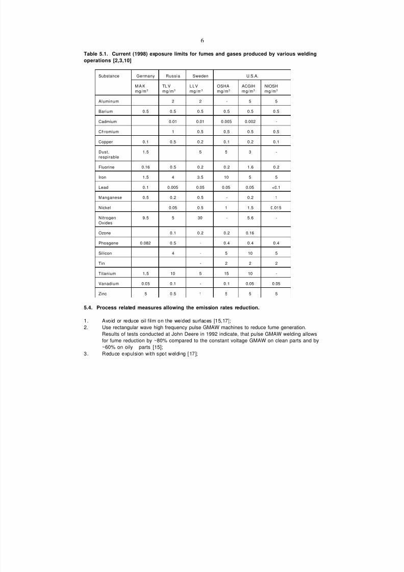
6
Table 5.1. Current (1998) exposure limits for fumes and gases produced by various welding
operations [2,3,10]
Substance Germany Russia Sweden U.S.A.
M A K
mg/m3
TL V
mg/m3
LLV
mg/m3
OSHA
mg/m3
ACGIH
mg/m3
NIOSH
mg/m3
Aluminum 2 2 - 5 5
Barium 0.5 0.5 0.5 0.5 0.5 0.5
Cadmium 0.01 0.01 0.005 0.002 -
Chromium 1 0.5 0.5 0.5 0.5
Copper 0.1 0.5 0.2 0.1 0.2 0.1
Dust,
respirable
1.5 5 5 3 -
Fluorine 0.16 0.5 0.2 0.2 1.6 0.2
Iron 1.5 4 3.5 10 5 5
Lead 0.1 0.005 0.05 0.05 0.05 <0.1
Manganese 0.5 0.2 0.5 - 0.2 1
Nickel 0.05 0.5 1 1.5 0.015
Nitrogen
Oxides
9.5 5 30 - 5.6 -
Ozone 0.1 0.2 0.2 0.16
Phosgene 0.082 0.5 - 0.4 0.4 0.4
Silicon 4 - 5 10 5
Tin - 2 2 2
Titanium 1.5 10 5 15 10 -
Vanadium 0.05 0.1 - 0.1 0.05 0.05
Zinc 5 0.5 1 5 5 5
5.4. Process related measures allowing the emission rates reduction.
1. Avoid or reduce oil film on the welded surfaces [15,17];
2. Use rectangular wave high frequency pulse GMAW machines to reduce fume generation.
Results of tests conducted at John Deere in 1992 indicate, that pulse GMAW welding allows
for fume reduction by ~80% compared to the constant voltage GMAW on clean parts and by
~60% on oily parts [15];
3. Reduce expulsion with spot welding [17];

7/18/2019 Ventilation Guide
http://slidepdf.com/reader/full/ventilation-guide 25/223
7
4. Avoid short-time conditions with spot welding, changing over to medium-time conditions [17].
1985);
5. Place containers with welded small parts in the totally enclosed cabinets connected to exhaust
system to avoid residual welding smoke release into the building (Figure 5.1) (Fiat, Turin).
5.5. Ventilation
5.5.1. Principles of Ventilation
Clean air for welding operations is provided by ventilation systems, which typically consist of local
exhaust systems and general ventilation supply and exhaust systems. The most efficient methods of
contaminant control in the occupied zone of the welding shop, and particularly in the breathing zone
of the operator or welder (with a manual welding), are:
• exhaust from the total welding process enclosure when automatic welding machines are used
(Figure 5.2);
• exhaust from the welding area enclosure, when robotic welding and material handling are used(Figure 5.3), and
• local exhaust which captures the contaminants at or near their source.
Exhaust from enclosures separating welding process from the operator's environment, or local
exhaust systems with manual and semiautomatic welding operations are normally the most cost-
effective solutions to fume control. They minimize the required outdoor airflow rate thus optimizing
system installation and operating costs especially where filtered air return back into the building is not
used. Control of fumes in the source area can also reduce plant maintenance costs. A cleaner
workplace may also lead to an in increase in employee productivity.
No local exhaust ventilation system is 100% effective in capturing fumes. However, it is important to
note that capture efficiency has a greater influence on air quality than filtration efficiency. No filterdevice is effective until the fume is drawn into it. In addition, there will be circumstances, because of
the size or mobility of the welding zone, where installation of local exhaust ventilation systems may
not be possible. Also, local exhausts are typically not efficient in removing fumes generated after
welding at the heat-affected zone.
General ventilation is needed to dilute pollutants not captured by the local ventilation system and to
dilute fumes generated after welding. General ventilation systems supply make-up air to replace air
extracted by local and general exhaust systems. Also, supply air is used to heat and cool the building.
Volume of outside air to be supplied by a general ventilation system should exceed the volume of air
exhausted by local ventilation systems. Buildings should be pressurized to prevent air infiltration
creating cold drafts in winter, and hot humid air in summer. In addition to local exhaust system, a
general exhaust system is used to evacuate air from the building.
Special attention should be paid to ventilation of areas with grinding and polishing operations.
Especially, in the case with aluminum production. Air supply and exhaust should be arranged such to
create low velocity-low turbulent airflow preventing dust dispersion in the shop (Figure 5.2.) Low
airflow, high vacuum exhaust systems built-in grinding and polishing machines significantly reduce
contaminant load on the building.

7/18/2019 Ventilation Guide
http://slidepdf.com/reader/full/ventilation-guide 26/223
8
5.5.2. Local Exhaust Ventilation
Total (or complete) enclosure is a box or housing mounted around or built into the welding machine
(Figure 5.3). The enclosure is not intended to be air tight. Limited openings might be required by the
process needs. They also provide a path for replacement air to enter.
Robotic welding areas or a part of conveyor with welding operations can be enclosed using a large
canopy hood with a perimeter plastic curtain (Figure 5.4). The size and design of the hood should limit
free area to reduce exhausted airflow rate. Location and size of the openings should allow
components entrance to and exit from the welding area. Similar enclosures can be used to contain
and direct residual emissions in the part of conveyor transporting welded parts from automated
welding machines. (Figure 5.5).
The enclosure is kept under negative pressure by the exhaust system connected to the hood. The
exhaust airflow rate must be sufficient to prevent contaminants from escaping from the enclosure.
According to BEI and the DaimlerChrysler Process Group, a control velocity of 0.5 to 0.75 m/s wouldbe required in the openings and in the slot between the plastic curtain and the floor [30].
Local exhaust systems for manual and semiautomatic welding processes capture air contaminants
close to their source. These systems will only be effective if they are correctly designed, installed,
maintained, and used. The exhaust airflow through hoods should maintain capture velocity at the
point of fume generation between 0.5 and 0.75 m/s [6].
Stationary, mobile or portable local exhaust ventilation systems may consist of the following basic
elements: capture hood, duct system, air-cleaning device, fan, and outlet discharge ductwork. These
elements must be specifically engineered for each application . They must remove fume while not
disturbing the welding process. For example the fume capture velocity at the weld zone must not
disturb the shielding gas.
Effective control of worker exposure to dusts from polishing and grinding operations on can be
achieved by use of polishing and grinding equipment with a built-in high velocity, low volume local
exhaust ventilation as part of the tool's design.
The choice of local ventilation system type depends on the method and conditions of welding, type of
welding equipment, size of the welded components and shop space factors. Typical systems are
shown in Table 5.2.
7/18/2019 Ventilation Guide
http://slidepdf.com/reader/full/ventilation-guide 27/223
9
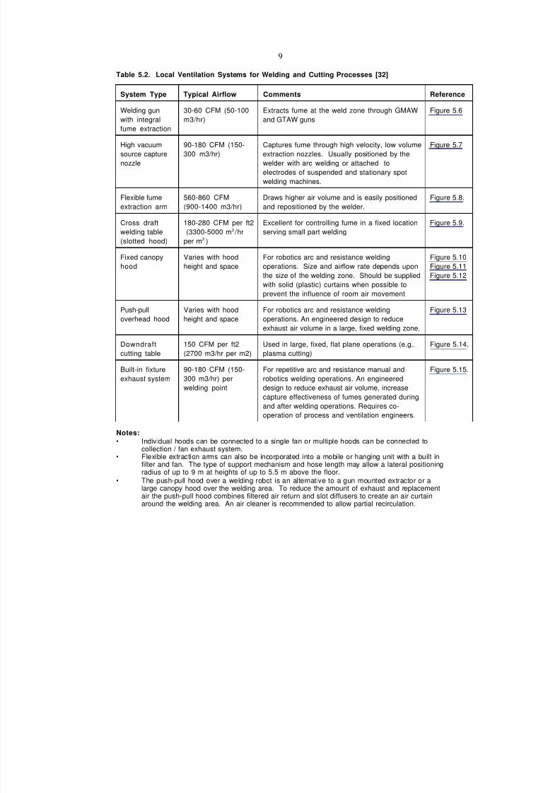
Table 5.2. Local Ventilation Systems for Welding and Cutting Processes [32]
System Type Typical Airflow Comments Reference
Welding gun
with integral
fume extraction
30-60 CFM (50-100
m3/hr)
Extracts fume at the weld zone through GMAW
and GTAW guns
Figure 5.6
High vacuum
source capture
nozzle
90-180 CFM (150-
300 m3/hr)
Captures fume through high velocity, low volume
extraction nozzles. Usually positioned by the
welder with arc welding or attached to
electrodes of suspended and stationary spot
welding machines.
Figure 5.7
Flexible fume
extraction arm
560-860 CFM
(900-1400 m3/hr)
Draws higher air volume and is easily positioned
and repositioned by the welder.
Figure 5.8.
Cross draft
welding table
(slotted hood)
180-280 CFM per ft2
(3300-5000 m3 /hr
per m2 )
Excellent for controlling fume in a fixed location
serving small part welding
Figure 5.9.
Fixed canopy
hood
Varies with hood
height and space
For robotics arc and resistance welding
operations. Size and airflow rate depends upon
the size of the welding zone. Should be supplied
with solid (plastic) curtains when possible to
prevent the influence of room air movement
Figure 5.10
Figure 5.11
Figure 5.12
Push-pull
overhead hood
Varies with hood
height and space
For robotics arc and resistance welding
operations. An engineered design to reduceexhaust air volume in a large, fixed welding zone.
Figure 5.13
Downdraft
cutting table
150 CFM per ft2
(2700 m3/hr per m2)
Used in large, fixed, flat plane operations (e.g.,
plasma cutting)
Figure 5.14.
Built-in fixture
exhaust system
90-180 CFM (150-
300 m3/hr) per
welding point
For repetitive arc and resistance manual and
robotics welding operations. An engineered
design to reduce exhaust air volume, increase
capture effectiveness of fumes generated during
and after welding operations. Requires co-
operation of process and ventilation engineers.
Figure 5.15.
Notes:• Individual hoods can be connected to a single fan or multiple hoods can be connected to
collection / fan exhaust system.• Flexible extraction arms can also be incorporated into a mobile or hanging unit with a built in
filter and fan. The type of support mechanism and hose length may allow a lateral positioningradius of up to 9 m at heights of up to 5.5 m above the floor.
• The push-pull hood over a welding robot is an alternative to a gun mounted extractor or alarge canopy hood over the welding area. To reduce the amount of exhaust and replacementair the push-pull hood combines filtered air return and slot diffusers to create an air curtainaround the welding area. An air cleaner is recommended to allow partial recirculation.
7/18/2019 Ventilation Guide
http://slidepdf.com/reader/full/ventilation-guide 28/223
10
5.5.3. General Ventilation (see chapters 9, 10, 11)
5.5.4. Fume Filtration
5.5.4.1. Collector Selection. Often when air is exhausted, it is exhausted through a fume/dust
collector. These collectors may be:
• small, portable collectors connected to the local exhaust and the fan;
• medium size wall- or floor-mounted collectors working as part of the local exhaust system
with one or few exhaust hoods, or
• large collectors that may work with either a centralized local exhaust system or with a general
exhaust system.
It should be noted that most of collectors used in welding shops are designed to remove solid matter
(fume) only and not gases. It is not cost efficient to use collectors capable of efficient removal of
gaseous byproducts.
Collectors are selected based on the following factors:1. Contaminant Concentration. The amount of dust and fume generated by the process.
2. Efficiency Requirements. Capture efficiency generally has greater influence on air quality than
filtration efficiency. However, the filtration efficiency required must be sufficient to meet all
national and local codes and standards (OSHA, EPA, etc.). HEPA filters are those classified
with an initial efficiency of 99.97% at 0.3 micron (DOP test) but are not typically required in
most welding applications.
3. Contaminant Characteristics. These include contaminant size and condition such as wet, dry
or sticky.
4. Energy Consumption. All collectors consume energy in order to overcome pressure drop
through the collector. The pressure drop is measured in Pa (inches of water). Energy is also
consumed during the cleaning of contaminant from collectors.
5. Maintenance costs. Some collectors can be cleaned on-line, others require cleaning orreplacement of filtration elements.
There are two major types of collectors used in welding fume control.
1. Cartridge Collectors,
2 . Electrostatic Precipitators
5.5.4.2. Cartridge Collectors (Figure 5.16). Cartridge collectors use filters made out of pleated
paper or synthetic filter media. This type of cartridge results in a much larger amount of filter media
per collector volume than media used in conventional fabric filters. In addition, the type of filter media
used in these cartridges is usually much more efficient on sub-micron sized particulate with filtration
efficiencies exceeding 99%. It should be noted that while cartridge filters are generally more efficient
on sub-micron sized particles, performance depends on the filter media used in the cartridge itself. Allcartridges have a similar appearance regardless of efficiency. Specifications should define the
filtration efficiency of the unit on sub-micron sized particles.
Cartridge collectors are relatively easy to maintain. Maintenance involves replacement of the non
cleanable cartridge when pressure drop significantly decreases fume capture. Non cleanable cartridges
are normally used in small portable collectors.
Many cartridge collectors are cleaned on line, using a reverse pulse of compressed air. Cartridge life is
7/18/2019 Ventilation Guide
http://slidepdf.com/reader/full/ventilation-guide 29/223
11
usually quite long on welding fume applications with a cleanable cartridge change required
approximately once per year. Cartridge life can vary significantly with the application and type o f
media used. Most cartridges are relatively compact, easy to handle, and often can be changed from
outside the collector.
Disadvantages of cartridges include a relatively higher pressure drop (500 to 1000 Pa) than an
electrostatic precipitator (an inch or less) and the requirement for compressed air for cleaning. Filter
life may be reduced if the welding fume is very oily. Special measures should be considered to protect
cartridges from burning.
5.5.4.3. Electrostatic Precipitators (Figure 5.17). Electrostatic precipitators operate by electrically
charging dust and fume particles and collecting the charged particles on oppositely charged collector
plates. This type of filtration has been used for many years on welding fume because it is effective on
small, sub-micron sized particles. Also, the pressure drop through this type of collector is usually the
lowest of the available options, allowing reduced horsepower blowers. Finally, unlike the other
collector options, there is no filter to replace.
Disadvantages include the requirement for frequent maintenance. The collection plates must be
cleaned frequently to maintain filtration efficiency and remove collected contaminant. The plates can
be cleaned manually, by mechanical shaking, or with a water wash. In addition, these units are not
well suited for collecting high concentrations of dust and fume. As particulate is collected, filter
efficiency is reduced.
Filtration efficiency varies from 90% to 99% on sub-micron sized particles.
5.5.5. Fire and explosion protection for exhaust systems
Welding exhaust systems by their nature have the capability to capture sparks that can be
transported to the welding fume collector and starting a fire. There are many documented cases in
the automotive industry where welding exhaust sparks have started fires in the duct and dustcollectors. Fire protection systems need to be evaluated for each application. Local and national
codes should be used as a basis of the design of the fire protection system. The local fire protection
authority should be contacted for concurrence with the design and type of fire protection system(s)
used.
The types of fire protection systems are water and gas (typically CO 2) with an automatic and/or
manual discharge system. Consideration should be given to providing a drop out chamber for the
welding process dust particles and sparks. This drop out chamber should be located as close to the
welding process as possible. See the latest edition of the ACGIH Industrial Ventilation Manual [1] for
guidance.
Some plants require that welding fume exhaust duct have fire sprinklers located from the weldinghood to the drop out chamber. If the duct has fire protection sprinklers installed the static pressure
should be adjusted accordingly. Some fire codes allow ducts less than 100 square inches to not have
fire protection sprinklers installed. If the exhaust duct has fire protection sprinklers care should be
taken to avoid water draining from the duct on to the welding robots or machinery. The ducts should
be sloped to a drain, with a trap, discharging where the water will be less of a problem. The welding
fume collector should have fire protection system installed. This is typically done with an automatic
and/or manual fire protection system.
7/18/2019 Ventilation Guide
http://slidepdf.com/reader/full/ventilation-guide 30/223
12
In cases of welding processes using materials that have the potential of forming explosive dust
particles (such as aluminum, magnesium, etc.), great care must be used in providing the fire protection
system. Consideration must be given to providing some sort of explosion pressure relief (blow out
panels etc.) for the duct work, drop out chamber, welding fume collector, and any other locations
where the potentially explosive dust can accumulate.
5.5.6. Explosion protection with aluminum grinding and polishing operations.
Very precise guidelines and precautionary measures must be applied for the grinding and polishing of
aluminum in body shops. If they are not taken into account, there is a risk of an aluminum-dust
explosion. The goal is to prevent the accumulation of particles in the complete system in order to
avoid the risk of an explosion. To better understand the danger of dust-explosions and to avoid them
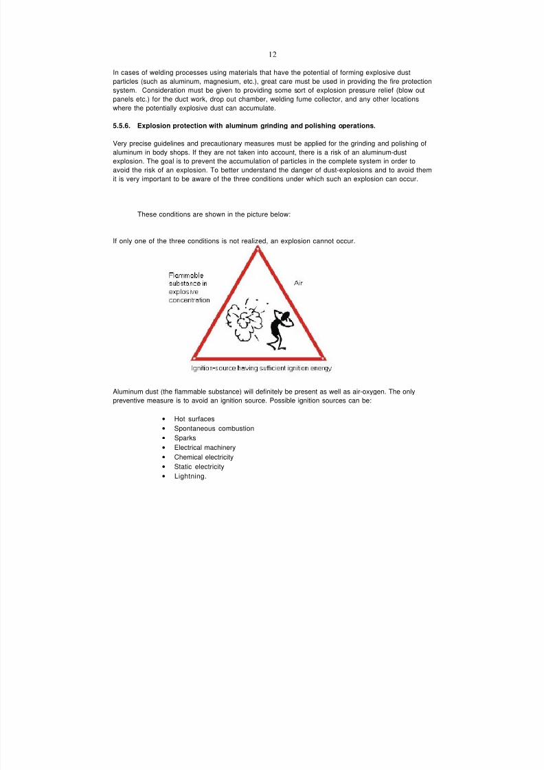
it is very important to be aware of the three conditions under which such an explosion can occur.
These conditions are shown in the picture below:
If only one of the three conditions is not realized, an explosion cannot occur.
Aluminum dust (the flammable substance) will definitely be present as well as air-oxygen. The only
preventive measure is to avoid an ignition source. Possible ignition sources can be:
• Hot surfaces
• Spontaneous combustion
• Sparks
• Electrical machinery
• Chemical electricity
• Static electricity
• Lightning.

7/18/2019 Ventilation Guide
http://slidepdf.com/reader/full/ventilation-guide 31/223
13
The next step to avoid an explosion is to keep the concentration of aluminum powder as low as
possible. A good ventilation system is therefore required. To prevent the dust from expanding in large
production halls, the process of grinding/polishing should be performed in a booth. (Figure 5.18.)
Most of the aluminum-particles should be directly extracted from around the grinding machine to
prevent their spreading in the cubicle. In fact, the exhaust built-in machine will not extract a high
percentage of the particles. Therefore the ventilation of the cubicle should assure the removal of the
remaining aluminum-particles.
The airflow exhausted from the cubicle should always exceed the airflow supplied into the booth. This
controls the aluminum dust within the booth and prevents its dispersion into the shop. A pressure
inside the cubicle should be always lower than in shop.
The air exhausted from the booth requires cleaning by either dry collection systems or wet collection
systems. These cleaning methods have the following disadvantages:
Dry collection systems :
- Danger of explosion in dust collector;
The nesessary explosion suppression is expensive.
Wet collection system:
- H2 – generation:
2Al + 3H2 O ‡ Al2O3 + 3H2
- Reaction after separation;
- Aluminum gets stuck in pipes.
The most important issue is to prevent an explosion. To accomplish this goal, the wet collection
systems are the best solution. As soon as aluminum is in contact with water, the risk of an explosion
is reduced. It is important, that such wet collection systems are designed to prevent accumulation ofexplosive hydrogen gas. Due to disadvantages of wet collection systems, dry collection systems
should also be considered.
The Aluminum Association recommends [5] that the following guidelines apply to both wet and dry
collection systems:
• Dust collection equipment and ducts should be of non-sparking rust-proof material.
• Each dust producing machine should have its own dedicated dust collection system.
• Ducts should be as short and straight as possible.
• The entire system should be grounded in accordance with [21] to prevent the accumulation of
static electricity.
• The minimum conveying air flow velocity should be 4500 feet per minute.• The maximum concentration of aluminum fines in the duct work should be kept below the
lower explosive limit for the aluminum dust being conveyed.
In both wet and dry collection systems, ducts should have smooth interior surfaces with internal lap
joints facing the direction of the airflow. The system should be designed to prevent the accumulation
of dust [20]. Additionally the sludge or fines should be removed from both systems at least once a
day.
7/18/2019 Ventilation Guide
http://slidepdf.com/reader/full/ventilation-guide 32/223
14
Dry dust collectors should be located outside the building and provided with deflagration relief
venting [20]. Venting should be to a safe area. To prevent the possibility of flashback down the inlet
duct a method of explosion isolation in the inlet duct should also be installed. An example of a suitable
mechanical isolation device is a high-speed deflagration isolation valve triggered by a deflagration
within the dust collector. Because of the danger of flashback, recycling of air back into the building is
prohibited [20].
The Aluminum Association recommends that high efficiency cyclone collectors be used instead of
media type collectors [5]. If media type collectors are used they should be conductive to prevent the
build-up of static electricity [20].
Wet type dust collection systems present a hydrogen gas explosion hazard. Therefore the sump
within these systems should be ventilated at all times to prevent hydrogen gas accumulation [20].
5.6 References
1. ACGIH. 1998. Industrial Ventilation. A Manual of Recommended Practice. 23 edition.
American Conference of Government Industrial Hygienists. Cincinnati, OH.
2. ACGIH. 1998. Guide to Occupational Exposure Values – 1998. American Conference of
Governmental Industrial Hygienists. Cincinnati, OH.
3. AFS 1996:2. 1996. Occupational Exposure Limit Values. The Swedish National Board of
Occupational Safety and Health.
4. AIHA. 1984. Welding Health and Safety. Resource Manual. American Industrial Hygiene
Association. Akron, OH.
5. Aluminum Association, 1992. F1 - Guidelines for Handling Aluminum Fines Generated During
Various Aluminum Fabricating operations. Washington, DC.
6. ASHRAE. 1999. ASHRAE Handbook. HVAC Applications. American Society of Heating,
Refrigerating and Air-Conditioning Engineers. Atlanta, GA.7. AWS. 2001. Ventilation Guide for Weld Fume. American Welding Society. Miami, FL.
8. AWS. 1979. Fumes and Gases in the Welding Environment. A Research Report on Fumes
and Gases Generated During Welding Operations. AWS. Miami, FL.
9. Cemedine. 1999. Private communications with Dr. Rick Snyder - R&D director Cemedine,
U.S.A., Inc. February 25, 1999.
10. GOST. 1988. General Requirements to the Occupied Zone Air. GOST 12.1.005-88. Moscow.
11. HMSO. 1990. Assessment of exposure to fume from welding and allied processes.
Guidance note EN-54 from Health and Safety Executive. March. UK.
12. HMSO. 1990. The control of exposure to fume from welding, brazing and similar processes.
Guidance Note EN-55 from Health and Safety Executive. April. UK.
13. Industrial Ventilation - 70 Examples. 1987. Bengsson-Back. Arbetarskyddnamanden.
Stockholm (In Swedish).14. INRS. 1990. Guide for Ventilation Practice #7 - ED 668. Arc welding operations. INRS.
Paris (In French).
15. John Deere. 1998. Private communications with Bruce Davis and Davis Trees.
16. Kötting, G und G. Schmid. Widerstandspunktschweißen geklebter und beschteter
Karosseriebleche: Verbindungseigenschaften, Technologie und Gefahrstoffemission. DVS
165.
17. Krause, H-J. and H. Press. 1985. Measurement of the welding fumes quantities and analysis
of the fume composition during resistance welding. Report published by the Sub-Department
7/18/2019 Ventilation Guide
http://slidepdf.com/reader/full/ventilation-guide 33/223
15
Joining Techniques of the Federal Institute for Materials Testing. Germany.
18. Mercedes-Benz U.S. International, Inc. 1999. Private communications with Mr. Richard
Burnis. Tuscaloosa, AL.
19. Naherne, G. 1993. Presentation at the AWS symposium, May, New Orleans. Data from
Welding Institute of Canada, Oakville, Ont.
20. NFPA. 1998. NFPA 651 Standard for the Machining and Finishing of Aluminum and the
Production and Handling of Aluminum Powders. National Fire Protection Association. Quincy,
MA.
21. NFPA. 1993. NFPA 77 Recommended Practice on Static Electricity. National Fire Protection
Association, Quincy, MA.
22. NIOSH. 1998. Recommended industrial ventilation guidelines. NIOSH technical information.
U.S. Department of Health, Education and Welfare. January.
23. Plymovent. 1998. Clean Fresh Air. Consultants Handbook. Industrial Products. Sweden:
Plymovent AB.
24. U.S. EPA. 1991. Developments of Environmental Release Estimates for Welding
Operations. Report on the project (contract no. 68-C9-0036, work assignment. no. 2-54,JTN 803812-16-2). IT Corporation. Cincinnati, OH.
25. US Patent. 1998. Device for removal of deleterious impurities from room atmosphere. U.S.
Patent # 5,716,268. February 1998.
26. VDI 2084. 1993. Raumlufttechnische Anlagen fur Schweißwerkstatten (Ventilation systems
for welding shops). Verein Deutscher Ingenieure, Dusseldorf. (In German).
27. Volvo. 1998. Celero Support AB. Private communications with Mr. Sten-Arne H@kansson.
28. VW. 1998. Private communications with Mr. Ulli Rudat.
29. Welders aren't made of steel. Thoughts and ideas for improved working conditions. 1990.
Swedish Work Environment Fund, Stockholm.
30. Zhivov, A. and J. Dolfi. 2000. Body shop ventilation design. Proceedings of the 3rd
International Conference “Ventilation for Automotive Industry”. March 13-15. Sao Paulo,
Brazil.31. Zhivov, A.M. and J.T. Ashe. 1997. Principles of Welding Fume Control. Proceedings of the
International Symposium "Ventilation '97". September 14-17, 1997. Ottawa, Canada.
32. Zhivov, A.M. 1990. Variable air volume systems for industrial spaces. ASHRAE
Transactions. Vol. 96(2). Atlanta, GA.

7/18/2019 Ventilation Guide
http://slidepdf.com/reader/full/ventilation-guide 34/223
16
Appendix 5.1. Fume Generation Data
Product Type
Shielding
Gas
Diameter Amperage
(A)
Voltage
( V)
Low hydrogen SMAW (EX018) -- 5/32" 175 - 180 21 - 22
Low Hydrogen SMAW (EX018) -- 1/8" 135 24 - 25
E6013 -- 5/32" 165 33
E7024 -- 5/32" 200 33
300 Series Stainless SMAW (E3XX-16) -- 1/8" 105 25
Flux-Cored Stainless (E3XXT1-1,-4) Ar/25%CO2 0.045" 200 27
E70T-5 CO2 0.093" 500 37
E70T-5 Ar/25%CO2 0.093" 500 37
First Generation FCAW (E7lT-1) CO2 1/16" 300 28
Second Generation FCAW (E71T-1) CO2 1/16" 300 28
First Generation FCAW (E71T-1) Ar/25%CO2 0.052" 220 24
Second Generation FCAW (E7lT-1) Ar/25%CO2 0.052" 220 24
Third Generation FCAW (E71T-1) Ar/10%CO2 0.045" 280 28
Third Generation FCAW (E7lT-1) Ar/10%CO2 1/16" 340 29
First Generation Metal Core (E70C-XM) Ar/25%CO2 0.045" 270 28
Second Generation Metal Core (E70C-XM) Ar/25%CO2 0.045" 270 28
Solid Wire - ER70S-3 CO2
AR/10% CO2
AR/5%O2
0.045
0.045
0.045
270-300
280 -310
280-310
29
28
28
Note: Because of rapidly developing formulation and manufacturing technology for flux and metal-cored wi
similar products in the marketplace. First generation represents original formulations and technology - produ
represents products released for sale in the last two years. See manufacturers information to determine an a
provided by Praxair, Inc., Tarrytown, NY
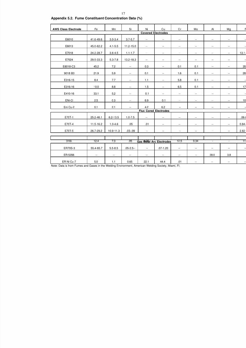
7/18/2019 Ventilation Guide
http://slidepdf.com/reader/full/ventilation-guide 35/223
17
Appendix 5.2. Fume Constituent Concentration Data (%)
AWS Class Electrode Fe Mn Si Ni Cu Cr Mo
Covered Electrodes
E6010 41.6-49.6 3.0-3.4 3.7-5.7 -- -- -- --
E6013 45.0-62.2 4.1-5.5 11.2-15.0 -- -- -- --
E7018 24.2-28.7 3.6-4.5 1.1-1.7 -- -- -- --
E7024 29.5-33.3 5.3-7.8 13.2-18.3 -- -- -- --
E8018-C3 45.2 7.2 -- 0.3 -- 0.1 0.1
9018 B3 21.9 5.9 -- 0.1 -- 1.6 0.1
E316-15 8.4 7.7 -- 1.1 -- 5.8 0.1
E316-16 10.0 8.8 -- 1.5 -- 6.5 0.1
E410-16 33.1 5.2 -- 0.1 -- -- --
ENi-Cl 2.5 0.3 -- 6.9 0.1 -- --
Eni Cu-2 0.1 2.1 -- 4.2 6.2 -- --
Flux Cored Electrodes
E70T-1 25.2-46.1 6.2-13.5 1.0-7.5 -- -- -- --
E70T-4 11.5-16.2 1.0-4.6 .05 .01 -- -- --
E70T-5 26.7-29.2 10.9-11.3 .05-.09 -- -- -- --
316L 12.4 7.3 .05 1.06 -- 12.5 0.34Gas Metal Arc Electrodes
ER70S-3 55.4-65.7 5.5-8.5 .05-2.5-- -- .07-1.20 -- --
ER-5356 -- -- -- -- -- -- --
ER Ni Cu-7 5.0 1.1 0.65 22.1 44.4 .01 --
Note: Data is from Fumes and Gases in the Welding Environment, American Welding Society, Miami, Fl.
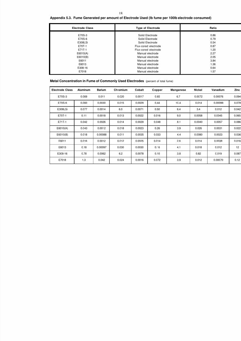
7/18/2019 Ventilation Guide
http://slidepdf.com/reader/full/ventilation-guide 36/223
18
Appendix 5.3. Fume Generated per amount of Electrode Used (lb fume per 100lb electrode cons
Electrode Class Type of Electrode
E70S-3
E70S-6
E308LSi
E70T-1E71T-1
E6010(A)
E6010(B)
E6011
E6013
E308-16
E7018
Solid Electrode
Solid Electrode
Solid Electrode
Flux-cored electrodeFlux-cored electrode
Manual electrode
Manual electrode
Manual electrode
Manual electrode
Manual electrode
Manual electrode
Metal Concentration in Fume of Commonly Used Electrodes (percent of total fume)
Electrode Class Aluminum Barium Chromium Cobalt Copper Manganese Nicke
E70S-3 0.069 0.011 0.020 0.0017 0.65 6.7 0.0072
E70S-6 0.060 0.0030 0.015 0.0029 0.44 10.4 0.014
E308LSi 0.077 0.0014 6.0 0.0071 0.50 6.4 3.4
E70T-1 0.11 0.0018 0.013 0.0022 0.016 9.0 0.0058
E71T-1 0.042 0.0026 0.014 0.0029 0.048 8.1 0.0040
E6010(A) 0.043 0.0012 0.018 0.0023 0.26 3.9 0.026
E6010(B) 0.018 0.00088 0.011 0.0035 0.033 4.4 0.0080
E6011 0.016 0.0012 0.012 0.0025 0.014 2.6 0.014
E6013 0.18 0.00097 0.030 0.0030 0.16 4.1 0.018
E308-16 0.78 0.0062 6.2 0.0078 0.10 3.8 0.82
E7018 1.3 0.042 0.024 0.0016 0.072 3.9 0.012
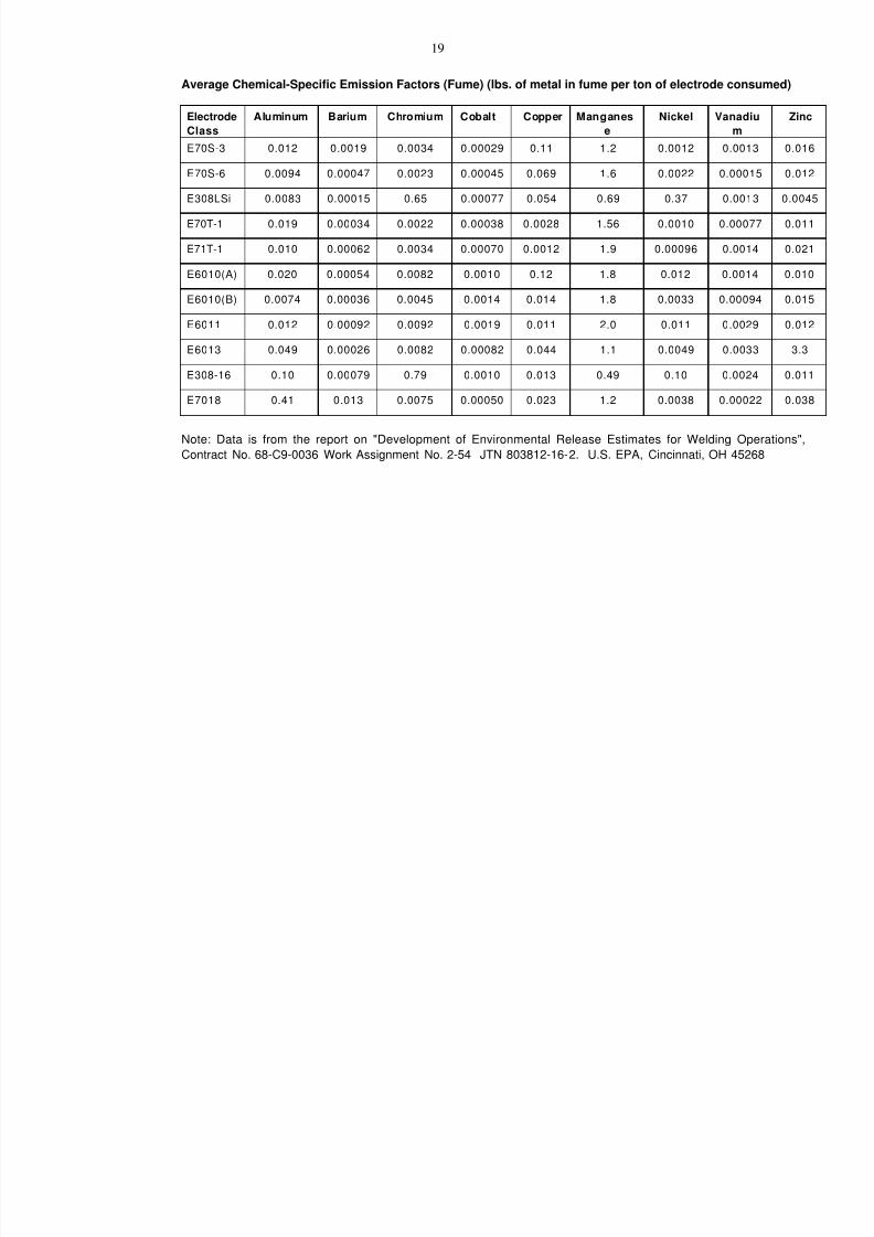
7/18/2019 Ventilation Guide
http://slidepdf.com/reader/full/ventilation-guide 37/223
19
Average Chemical-Specific Emission Factors (Fume) (lbs. of metal in fume per ton of electrode c
Electrode
Class
Aluminum Barium Chromium Cobalt Copper Manganes
e
Nickel Van
E70S-3 0.012 0.0019 0.0034 0.00029 0.11 1.2 0.0012 0
E70S-6 0.0094 0.00047 0.0023 0.00045 0.069 1.6 0.0022 0.
E308LSi 0.0083 0.00015 0.65 0.00077 0.054 0.69 0.37 0
E70T-1 0.019 0.00034 0.0022 0.00038 0.0028 1.56 0.0010 0.
E71T-1 0.010 0.00062 0.0034 0.00070 0.0012 1.9 0.00096 0
E6010(A) 0.020 0.00054 0.0082 0.0010 0.12 1.8 0.012 0.
E6010(B) 0.0074 0.00036 0.0045 0.0014 0.014 1.8 0.0033 0.
E6011 0.012 0.00092 0.0092 0.0019 0.011 2.0 0.011 0
E6013 0.049 0.00026 0.0082 0.00082 0.044 1.1 0.0049 0
E308-16 0.10 0.00079 0.79 0.0010 0.013 0.49 0.10 0
E7018 0.41 0.013 0.0075 0.00050 0.023 1.2 0.0038 0.
Note: Data is from the report on "Development of Environmental Release Estimates for Welding
Contract No. 68-C9-0036 Work Assignment No. 2-54 JTN 803812-16-2. U.S. EPA, Cincinnati, OH
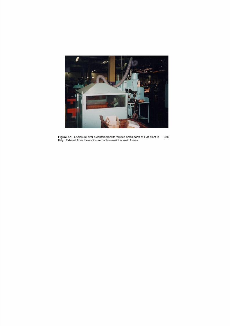
7/18/2019 Ventilation Guide
http://slidepdf.com/reader/full/ventilation-guide 38/223
!"#$%& ()*) "#$%&'()* &+*) , $&#-,.#*)' /.-0 /*%1*1 '2,%% 3,)-' ,- 4.,- 3%,#- .# 5().#67-,%89 ":0,('- ;)&2 -0* *#$%&'()* $&#-)&%' )*'.1(,% /*%1 ;(2*'9

7/18/2019 Ventilation Guide
http://slidepdf.com/reader/full/ventilation-guide 39/223
!
"
#
$%&'() +,-, "#$%&'( )&*+(,*- %&(./%(*0 %#+1 21+3*-4 /%0$*-1 %( 5/16*0%- 5#1+ %-3 7%-&8%0(&6*-4 9+%-(
*- :1(6.*(; 7*0$*4%-< ! , 41-16%+ =*12 .8 ($1 %&(./%(*0 21+3*-4 /%0$*-1 2*($ (2. 21+3*-4 >.'*(*.-'? " ,
+.0%+ 1#$%&'( 2*($ % .>16%)+1 (.(%+ 1-0+.'&61 %-3 %- %&(./%(*0 @A5B 4&-? # , 3&0( 'C'(1/ 1=%0&%(*-421+3 8&/1' 86./ 21+3*-4 '(%(*.-' .&('*31 ($1 )&*+3*-4D

7/18/2019 Ventilation Guide
http://slidepdf.com/reader/full/ventilation-guide 40/223
!
" $
%&'()* +, -, "#$%&' (%%) *+,( #$ #+- ./-,#+$ 0$.1%2+$3 &#-, %4 ,(0 .%$50'%- *+,( # -%6%,+. 2&%,*01)+$3 #-0# %4 ,(0 6%)' 2(%& #, ,(0 "(-'210- 7%-,( 80440-2%$ 9220:61' ;1#$,< # = 30$0-#1 5+0*> 6= *01)0) &#-,2 0?+, 4-%: ,(0 0$.1%2/-0> . = .%:&%$0$,2 0$,-#$.0 +$,% ,(0 0$.1%2/-0@

7/18/2019 Ventilation Guide
http://slidepdf.com/reader/full/ventilation-guide 41/223
Figure 5.4. Unidirectional flow ventilation for the polishing and grinding operations at the DaimlerChrysler body shop in Sindelfingen. Air is supplied through special panels with low velocity and low turbulence andis extracted through square opening in the floor with a grating cover. Two workplaces located on each
side of the car body are separated by the plastic curtain to prevent cross-contamination.

7/18/2019 Ventilation Guide
http://slidepdf.com/reader/full/ventilation-guide 42/223
!"#$%& ()() "# $%&'(&)* ($$* +,-( ) .&',/&-&' .0)1-,2 23'-),# )4$%& -(& 2$#%&5$' -')#1.$'-,#6+&0*&* .)'-1 7'$/ )3-$/)-&* +&0*,#6 /)2(,#&1 )- -(& "/&',2)# "8&0 )#* 9)#37)2-3',#6 .0)#- ,#:&-'$,-; 9,2(,6)#< =(& &8()31- 7'$/ -(& $13'& &%)23)-&1 '&1,*3)0 +&0*,#6 73/&1< >)2(+&0*,#6 /)2(,#& ()1 ) 1&.)')-& 2)#$.5 ($$* -$ 2$#-'$0 73/&1 *3',#6 -(& +&0*,#6 .'$2&11<
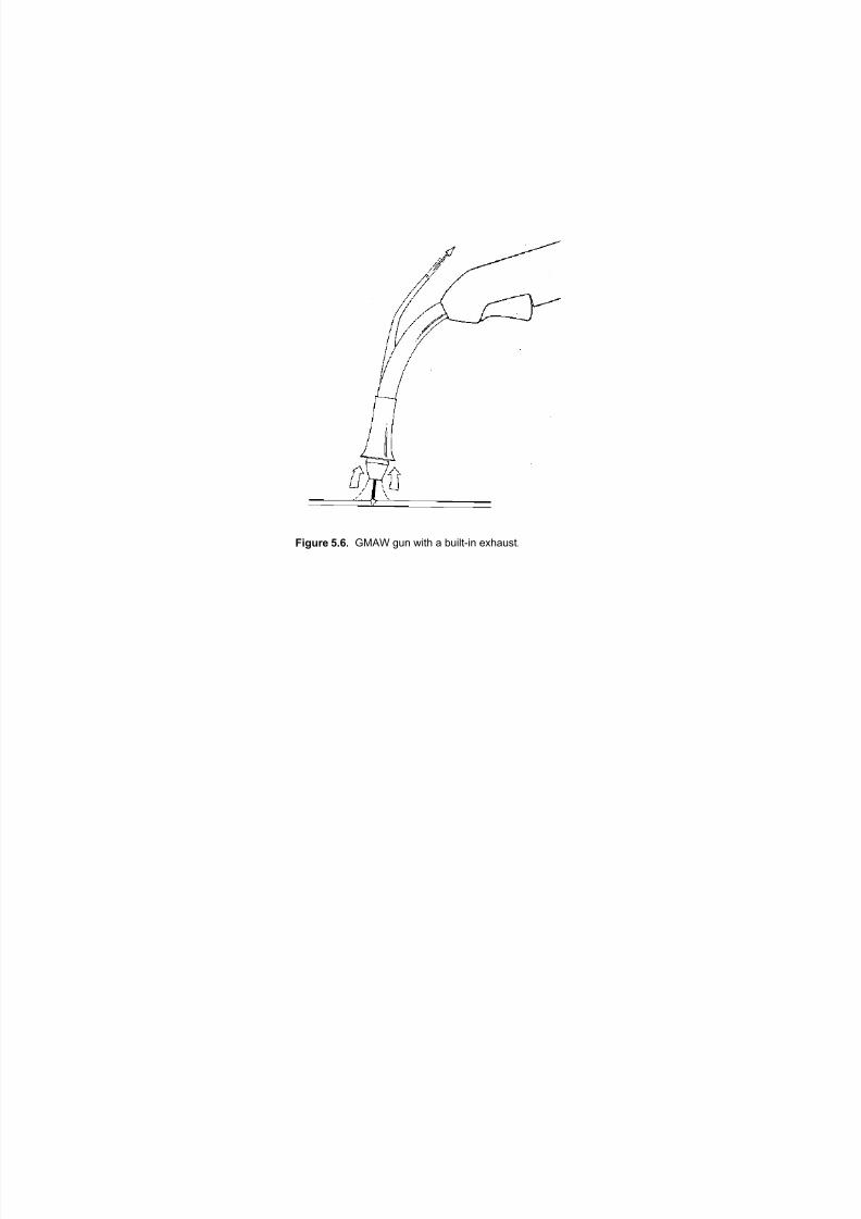
7/18/2019 Ventilation Guide
http://slidepdf.com/reader/full/ventilation-guide 43/223
Figure 5.6. GMAW gun with a built-in exhaust.
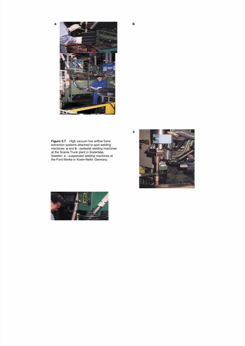
7/18/2019 Ventilation Guide
http://slidepdf.com/reader/full/ventilation-guide 44/223
Figure 5.7. High vacuum low airflow fumeextraction systems attached to spot welding
machines: a and b - pedestal welding machines
at the Scania Truck plant in Sodertalje,
Sweden; c - suspended welding machines at
the Ford Werke in Koeln-Neihl, Germany.
a b
c
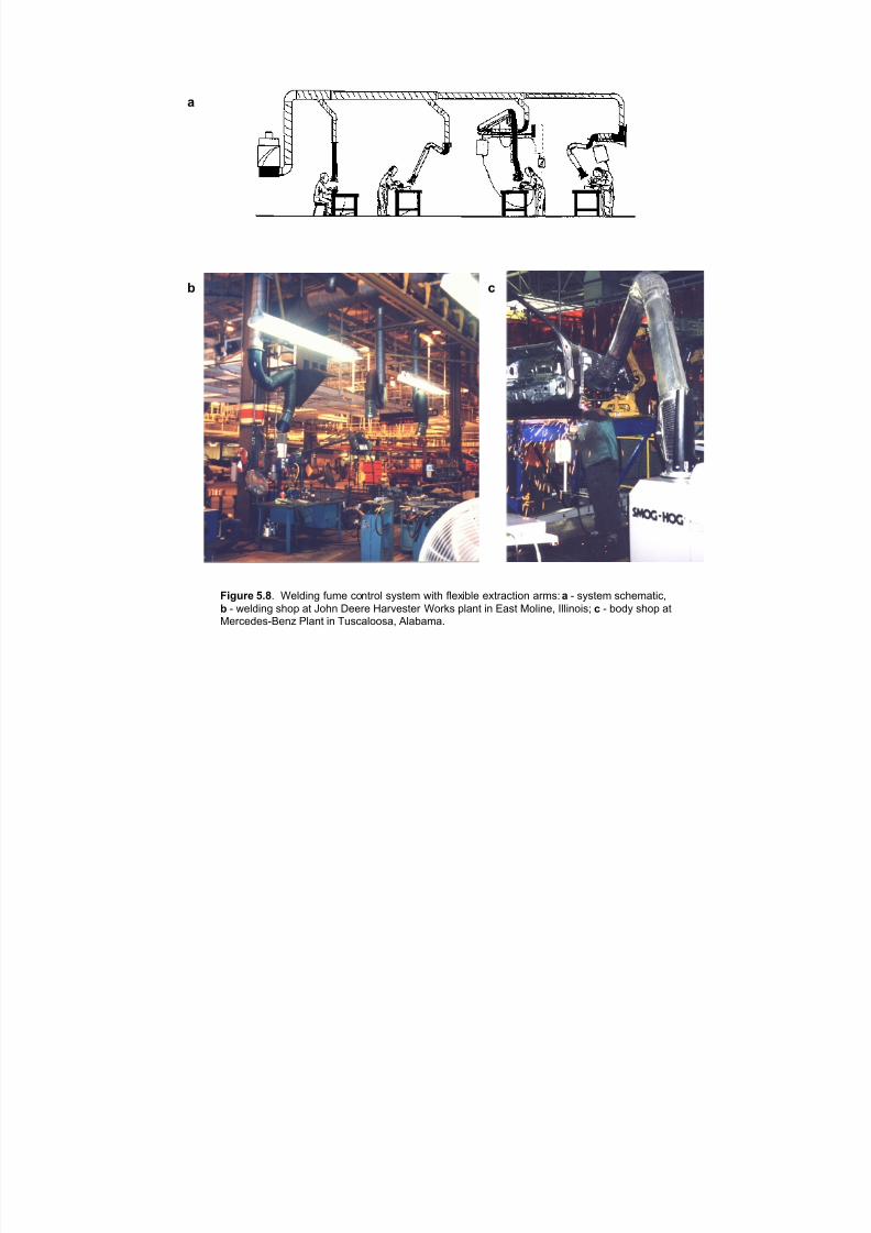
7/18/2019 Ventilation Guide
http://slidepdf.com/reader/full/ventilation-guide 45/223
!
" $
%&'()* +,-! #$%&'() *+,$ -.(/0.% 121/$, 3'/4 *%$5'6%$ $5/07-/'.( 70,18 ! 9 121/$, 1-4$,7/'-:
" 9 3$%&'() 14.; 7/ <.4( =$$0$ >70?$1/$0 #.0@1 ;%7(/ '( A71/ B.%'($: C%%'(.'1D $ 9 6.&2 14.; 7/B$0-$&$19E$(F G%7(/ '( H+1-7%..17: I%767,7!
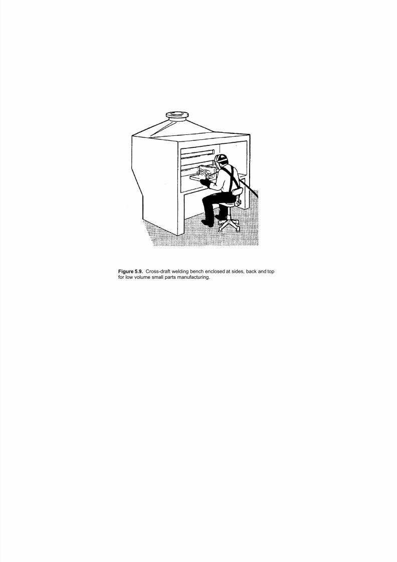
7/18/2019 Ventilation Guide
http://slidepdf.com/reader/full/ventilation-guide 46/223
Figure 5.9. Cross-draft welding bench enclosed at sides, back and topfor low volume small parts manufacturing.
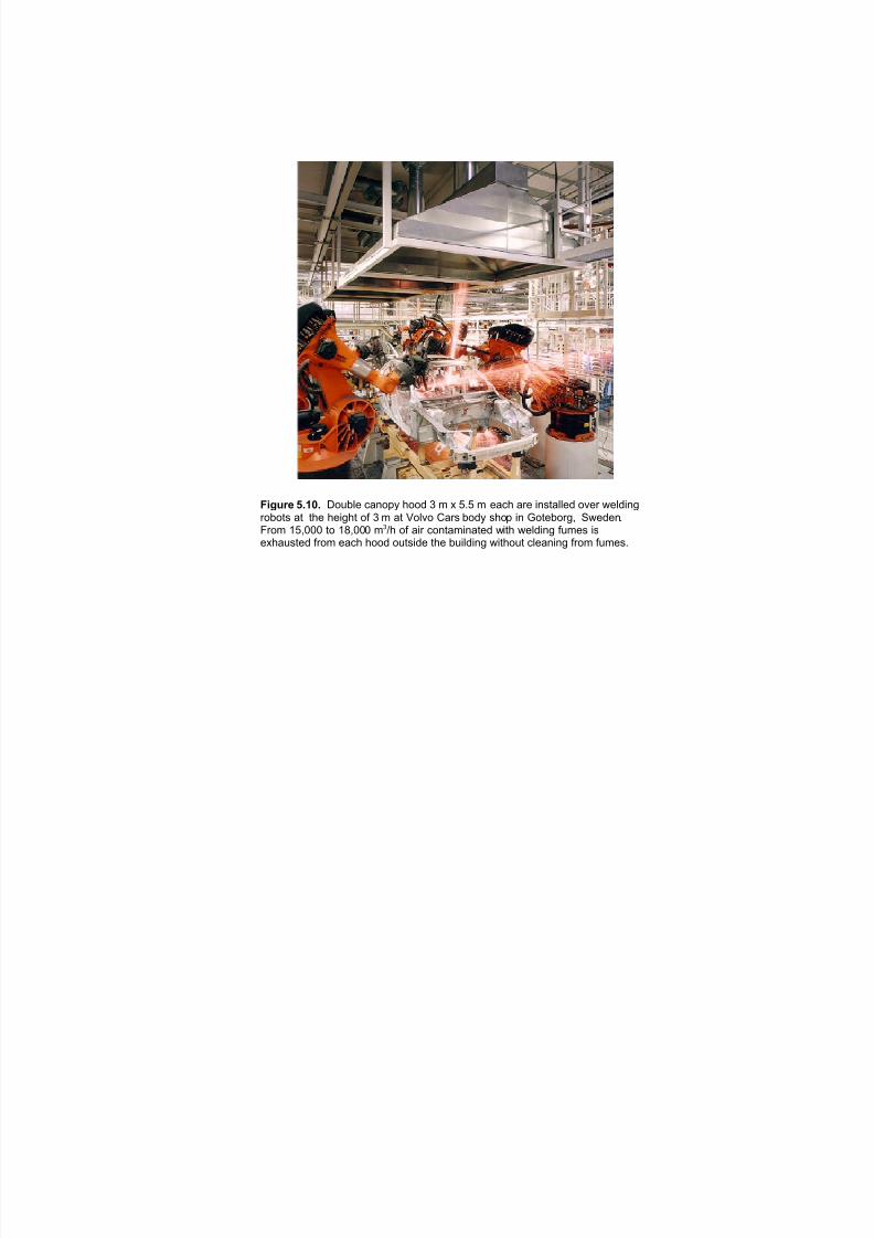
7/18/2019 Ventilation Guide
http://slidepdf.com/reader/full/ventilation-guide 47/223
Figure 5.10. Double canopy hood 3 m x 5.5 m each are installed over weldingrobots at the height of 3 m at Volvo Cars body shop in Goteborg, Sweden.
From 15,000 to 18,000 m /h of air contaminated with welding fumes is3
exhausted from each hood outside the building without cleaning from fumes.
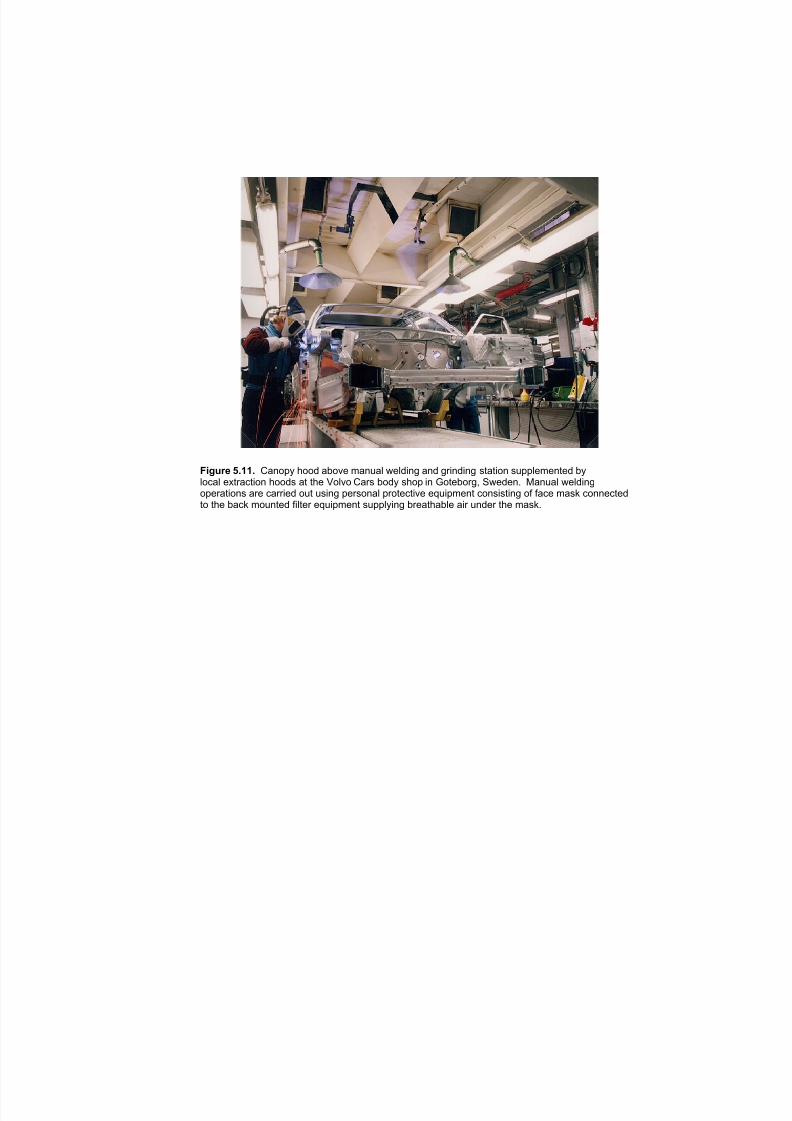
7/18/2019 Ventilation Guide
http://slidepdf.com/reader/full/ventilation-guide 48/223
Figure 5.11. Canopy hood above manual welding and grinding station supplemented bylocal extraction hoods at the Volvo Cars body shop in Goteborg, Sweden. Manual weldingoperations are carried out using personal protective equipment consisting of face mask connectedto the back mounted filter equipment supplying breathable air under the mask.
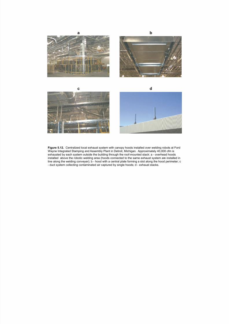
7/18/2019 Ventilation Guide
http://slidepdf.com/reader/full/ventilation-guide 49/223
Figure 5.12. Centralized local exhaust system with canopy hoods installed over welding robots at Ford
Wayne Integrated Stamping and Assembly Plant in Detroit, Michigan. Approximately 40,000 cfm is
exhausted by each system outside the building through the roof-mounted stack: a - overhead hoods
installed above the robotic welding area (hoods connected to the same exhaust system are installed in
line along the welding conveyer); b - hood with a central plate forming a slot along the hood perimeter; c
- duct system collecting contaminated air captured by single hoods; d - exhaust stacks.
a b
c d
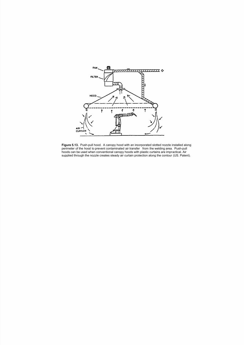
7/18/2019 Ventilation Guide
http://slidepdf.com/reader/full/ventilation-guide 50/223
Figure 5.13. Push-pull hood. A canopy hood with an incorporated slotted nozzle installed alongperimeter of the hood to prevent contaminated air transfer from the welding area. Push-pullhoods can be used when conventional canopy hoods with plastic curtains are impractical. Air supplied through the nozzle creates steady air curtain protection along the contour (US. Patent).
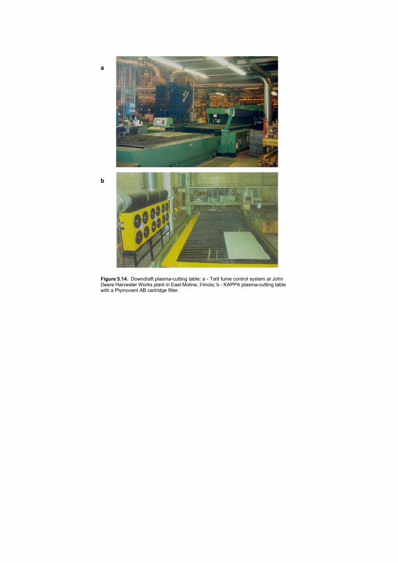
7/18/2019 Ventilation Guide
http://slidepdf.com/reader/full/ventilation-guide 51/223
!
"
#$%&'( *+,-+ "#$%&'()* +,(-.(/01**2%3 *(4,56 ( / 7#'2* )1.5 0#%*'#, -8-*5. (* 9#:%"55'5 ;('<5-*5' =#'>- +,(%* 2% ?(-* @#,2%5A B, ,2%#2-C 4 / DEFFE +,(-.(/01**2%3 *(4,5$2*: ( F,8.#<5%* EG 0('*'2&35 )2,*5'H
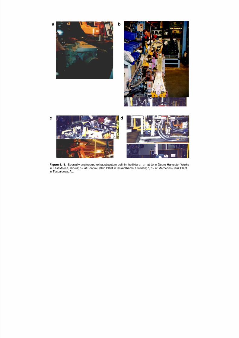
7/18/2019 Ventilation Guide
http://slidepdf.com/reader/full/ventilation-guide 52/223
D E
F G
)LJXUH èïìèï 6SHFLDOO\ HQJLQHHUHG H[KDXVW V\VWHP EXLOWðLQ WKH IL[WXUHã D ð DW -RKQ 'HHUH +DUYHVWHU :RUNVLQ (DVW 0ROLQHñ ,OOLQRLVâ E ð DW 6FDQLD &DELQ 3ODQW LQ 2VNDUVKDPQñ 6ZHGHQâ Fñ G ð DW 0HUFHGHVð%HQ] 3ODQWLQ 7XVFDORRVDñ $/ï
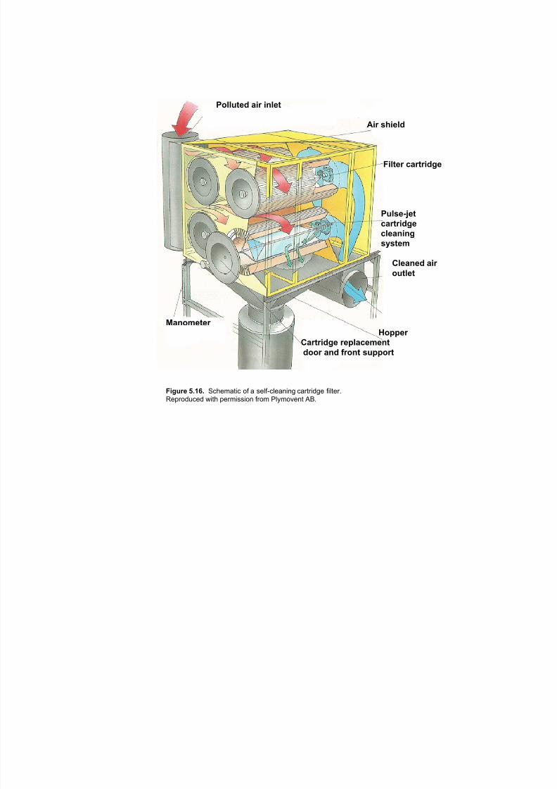
7/18/2019 Ventilation Guide
http://slidepdf.com/reader/full/ventilation-guide 53/223
!"##$%&' )*+ *,#&%
-*+ ./*&#'
0*#%&+ 1)+%+*'2&
!$#.&34&%1)+%+*'2&
1#&),*,2
.5.%&6
7#&),&' )*+
"$%#&%
8),"6&%&+ 9"::&+
7)+%+*'2& +&:#)1&6&,%
'""+ ),' ;+",% .$::"+%
0*2$+& <=>?= "#$%&'()# *+ ' ,%-+.#-%'/)/0 #'1(1)20% +)-(%134%51*26#%2 7)($ 5%1&),,)*/ +1*& 8-9&*:%/( ;<"

7/18/2019 Ventilation Guide
http://slidepdf.com/reader/full/ventilation-guide 54/223
CLEAN AIR
POLLUTED AIR
Figure 5. 17. Schematic of a two-stage electrostatic filter.
Reproduced with permission from Plymovent AB.

7/18/2019 Ventilation Guide
http://slidepdf.com/reader/full/ventilation-guide 55/223
Figure 5.18. Schematics of air supply and exhaust for the booth with aluminumgrinding and polishing operations.
7/18/2019 Ventilation Guide
http://slidepdf.com/reader/full/ventilation-guide 56/223
6. MACHINING PROCESSES
6.1. Process description
Machining operations are a form of metal cutting, grinding, drilling, milling, broaching, boring, honing,
polishing, etc. These operations may be done with (wet) or without (dry) the use of a metal working fluid,
(coolant), to remove heat and chips.
Dry machining is most often done for rough shaping of a part. More precise tolerance cutting is most often
done subsequent to the dry, rough shaping operations and is most often done wet (with MWF).
Machines may be single or multiple station designs but usually have some type of transport system
integrated into the machine design. These machines can be designed for all types of metal removal
operations , but usually do only one type of operation at each station.
Refer to Appendix 1 for a detailed list of various machines.
6.2. Contaminant Emissions
Contaminants released during dry machining operations are metal particles (dust) from the part being
machined, and from the machine tool. Particle size will vary depending on the specific operation from sub-
micron, to several microns.
Contaminants released during wet machining operations are in the form of vapor and mist from the metal
working fluid being used (Figure 6.1).
The contaminant emissions from machining operations may contain a solid or liquid particle in suspension
in the air, or a gas.
6.3. Target Levels
Occupational respiratory illnesses due to exposure to metalworking fluids include respiratory irritation,
bronchitis, pneumonia, pneumonitis, and extrinsic asthma. [5,12,15,18,21,23,26,40,41,42,43]
There is strong epidemiological evidence that exposures to all types of metalworking fluids cause
substantially elevated risk of cancer. Workers experience skin contact with machining fluids as a result of
splashing, dripping or leaking. Skin problems include irritation and allergic contact dermatitis [42]. They
also inhale mists and aerosols of these fluids generated during high speed, high friction, metalworking
operations. The use of synthetic cutting fluids has recently become questionable, due to discovery of
diethanol nitrosamine, a suspect cancirogen, as a product from the reaction of amones with nitrites. No
environmental limit exists for airborne concentrations of synthetic fluids, although standards may exist forspecific additives or components [31].
Table 6.1 shows examples of current exposure limits used in different countries or adopted by different
auto manufacturers for mists/vapors resulted from wet machining operations.
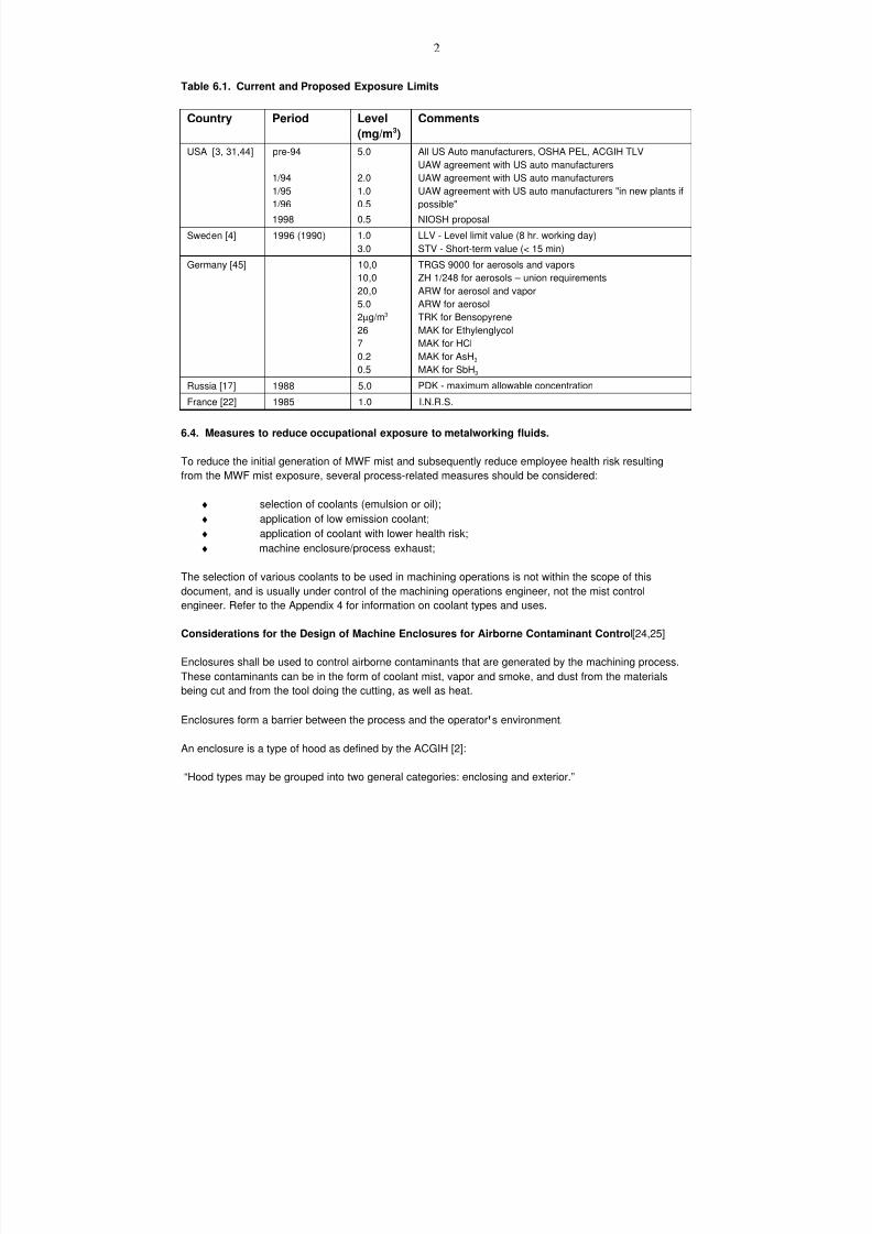
7/18/2019 Ventilation Guide
http://slidepdf.com/reader/full/ventilation-guide 57/223
2
Table 6.1. Current and Proposed Exposure Limits
Country Period Level
(mg/m3)
Comments
USA [3, 31,44] pre-94
1/94
1/95
1/96
1998
5.0
2.0
1.0
0.5
0.5
All US Auto manufacturers, OSHA PEL, ACGIH TLV
UAW agreement with US auto manufacturersUAW agreement with US auto manufacturers
UAW agreement with US auto manufacturers "in new plants if
possible"
NIOSH proposal
Sweden [4] 1996 (1990) 1.0
3.0
LLV - Level limit value (8 hr. working day)
STV - Short-term value (< 15 min)
Germany [45] 10,0
10,0
20,0
5.0
2µg/m3
267
0.2
0.5
TRGS 9000 for aerosols and vapors
ZH 1/248 for aerosols – union requirements
ARW for aerosol and vapor
ARW for aerosol
TRK for Bensopyrene
MAK for EthylenglycolMAK for HCl
MAK for AsH3
MAK for SbH3
Russia [17] 1988 5.0 PDK - maximum allowable concentration
France [22] 1985 1.0 I.N.R.S.
6.4. Measures to reduce occupational exposure to metalworking fluids.
To reduce the initial generation of MWF mist and subsequently reduce employee health risk resulting
from the MWF mist exposure, several process-related measures should be considered:
♦ selection of coolants (emulsion or oil);
♦ application of low emission coolant;
♦ application of coolant with lower health risk;
♦ machine enclosure/process exhaust;
The selection of various coolants to be used in machining operations is not within the scope of this
document, and is usually under control of the machining operations engineer, not the mist control
engineer. Refer to the Appendix 4 for information on coolant types and uses.
Considerations for the Design of Machine Enclosures for Airborne Contaminant Control [24,25]
Enclosures shall be used to control airborne contaminants that are generated by the machining process.These contaminants can be in the form of coolant mist, vapor and smoke, and dust from the materials
being cut and from the tool doing the cutting, as well as heat.
Enclosures form a barrier between the process and the operator's environment.
An enclosure is a type of hood as defined by the ACGIH [2]:
“Hood types may be grouped into two general categories: enclosing and exterior.”
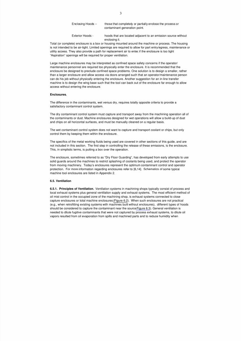
7/18/2019 Ventilation Guide
http://slidepdf.com/reader/full/ventilation-guide 58/223
3
Enclosing Hoods – those that completely or partially enclose the process or
contaminant generation point.
Exterior Hoods - hoods that are located adjacent to an emission source without
enclosing it.
Total (or complete) enclosure is a box or housing mounted around the machine or process. The housing
is not intended to be air-tight. Limited openings are required to allow for part entry/egress, maintenance or
utility access. They also provide a path for replacement air to enter, if the enclosure is too tight
“Aspiration” openings will be required for proper ventilation.
Large machine enclosures may be interpreted as confined space safety concerns if the operator/
maintenance personnel are required too physically enter the enclosure. It is recommended that the
enclosure be designed to preclude confined space problems. One solution is to design a smaller, rather
than a larger enclosure and allow access via doors arranged such that an operator/maintenance person
can do his job without physically entering the enclosure. Another suggestion for an in-line transfer
machine is to design the wing base such that the tool can back out of the enclosure far enough to allow
access without entering the enclosure.
Enclosures.
The difference in the contaminants, wet versus dry, requires totally opposite criteria to provide a
satisfactory contaminant control system.
The dry contaminant control system must capture and transport away from the machining operation all of
the contaminants or dust. Machine enclosures designed for wet operations will allow a build-up of dust
and chips on all horizontal surfaces, and must be manually cleaned on a regular basis.
The wet contaminant control system does not want to capture and transport coolant or chips, but only
control them by keeping them within the enclosure.
The specifics of the metal working fluids being used are covered in other sections of this guide, and are
not included in this section. The first step in controlling the release of these emissions, is the enclosure.
This, in simplistic terms, is putting a box over the operation.
The enclosure, sometimes referred to as “Dry Floor Guarding”, has developed from early attempts to use
solid guards around the machines to restrict splashing of coolants being used, and protect the operator
from moving machinery. Today’s enclosures represent the optimum contaminant control and operator
protection. For more information regarding enclosures refer to [6,14]. Schematics of some typical
machine tool enclosures are listed in Appendix 2.
6.5. Ventilation
6.5.1. Principles of Ventilation. Ventilation systems in machining shops typically consist of process and
local exhaust systems plus general ventilation supply and exhaust systems. The most efficient method of
oil mist control in the occupied zone of the machining shop, is exhaust systems connected to close
capture enclosures or total machine enclosures (Figure 6.2). When such enclosures are not practical
(e.g., when retrofitting existing systems with machines built without enclosures), different types of hoods
should be considered to capture the contaminant near the source Figure 6.3). General ventilation is
needed to dilute fugitive contaminants that were not captured by process exhaust systems, to dilute oil
vapors resulted from oil evaporation from spills and machined parts and to reduce humidity when
7/18/2019 Ventilation Guide
http://slidepdf.com/reader/full/ventilation-guide 59/223
4
emulsions are used as coolants. General ventilation systems supply make-up air to replace air extracted
by process and general exhaust systems. Also, supply air is used to heat and cool the building. Good
engineering practice is that the outside air supply should exceed the exhaust rate by 10%. Buildings
should be pressurized to prevent air infiltration creating cold drafts in the winter, and hot humid air in the
summer.
6.5.2. Process and Local Exhaust Ventilation. Local exhaust systems capture air contaminants very
close to their source. These systems will only be effective if they are correctly designed, installed,
maintained, and used. Local exhaust ventilation systems consist of the following basic elements: capture
hood or collector connected to machine enclosure, duct system, oil mist or dust collector, fan, and
discharge ductwork. Machine enclosure (e.g., Figure 6.4, Figure 6.5, Figure 6.6, Figure 6.8, Figure 6.9) or
hood (Figure 6.7) must be specifically engineered for each application.
Process Exhaust Design Principles:
Process exhaust systems within a facility performing machining operations serve a number of
critical services:
♦ Provide a means of creating a vacuum within the machine enclosure, or at the close-capture
hood.
♦ Provide a means of transporting aerosols from the machine enclosure to the mist collection
unit or dust collector.
♦ Provide a means of moving contaminant-laden air through the filtration or collection unit.
♦ Provide the means to re-introduce the cleaned air into the facility, or discharge to atmosphere
outside of the facility.
The design principles for process exhaust systems for “wet” machining with enclosures, and “dry”
machining are not the same!
♦ Wet machining (with enclosures) -The design principle is to contain the mist within the
enclosure.♦ Dry machining - The design principle is to capture the dust, and transport it to the
collection unit.
♦ Wet machining without enclosures) - The design principle is the same as for dry machining,
capture the aerosols, and transport them to the collection unit
The choice of local ventilation system type depends on type of machine and the process. Capture
velocities should be selected to adequately control vapors, smoke and mist being generated while not
removing chips, and metalworking fluids [24].
The capture velocity for coolant vapor and mist depends on the direction and inertia of the coolant vapor
and mist and the motion of the ambient air.
Capture or Control, this basic must be established to determine the correct airflow.
“Capture” – to capture the released emissions, the goal is to reach out from the face of a hood to the
point of emission release, and create sufficient air currents to pull the emissions to the
hood.
“Control” - to control the released emissions within an enclosure, he goal is create sufficient air
currents at each opening of the enclosure to prevent the escape of the emissions.
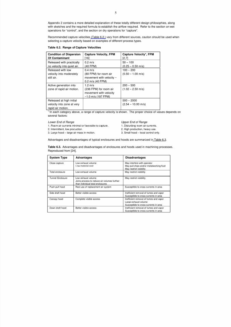
7/18/2019 Ventilation Guide
http://slidepdf.com/reader/full/ventilation-guide 60/223
5
Appendix 2 contains a more detailed explanation of these totally different design philosophies, along
with sketches and the required formula to establish the airflow required. Refer to the section on wet
operations for “control”, and the section on dry operations for “capture”.
Recommended capture velocities (Table 6.2.) vary from different sources, caution should be used when
selecting a capture velocity based on examples of different process types.
Table 6.2. Range of Capture Velocities
Condition of Dispersion
Of Contaminant
Capture Velocity, FPM
[16]
Capture Velocity*, FPM
[2,7]
Released with practically
no velocity into quiet air.
0.2 m/s
(40 FPM)
50 – 100
(0.25 – 0.50 m/s)
Released with low
velocity into moderately
still air.
0.4 m/s
(80 FPM) for room air
movement with velocity ~
0.2 m/s (40 FPM)
100 – 200
(0.50 – 1.00 m/s)
Active generation into
zone of rapid air motion.
1.2 m/s
(236 FPM) for room airmovement with velocity
~1.0 m/s (197 FPM)
200 – 500
(1.02 – 2.50 m/s)
Released at high initial
velocity into zone at very
rapid air motion.
500 – 2000
(2.54 – 10.00 m/s)
*) In each category above, a range of capture velocity is shown. The proper choice of values depends on
several factors:
Lower End of Range Upper End of Range
1. Room air currents minimal or favorable to capture. 1. Disturbing room air currents.
2. Intermittent, low production. 2. High production, heavy use.
3. Large hood – large air mass in motion. 3. Small hood – local control only.
Advantages and disadvantages of typical enclosures and hoods are summarized in Table 6.3.
Table 6.3. Advantages and disadvantages of enclosures and hoods used in machining processes.
Reproduced from [24].
System Type Advantages Disadvantages
Close capture Low exhaust volumeLow material cost
May interfere with operatorMay pull chips and/or metalworking fluid
May restrict visibility
Total enclosure Low exhaust volume May restrict visibility
Tunnel Enclosure Low exhaust volume
Joins process to reduce air volumes furtherthan individual total enclosures
May restrict visibility
Push-pull hood Best use of replacement air system Susceptible to cross currents in area
Side draft hood Better visible access Inefficient removal of fumes and vapor
Susceptible to cross currents in area
Canopy hood Complete visible access Inefficient removal of fumes and vapor
Large exhaust volume
Susceptible to cross currents in area
Down draft hood Better visible access Inefficient removal of fumes and vapor
Susceptible to cross currents in area
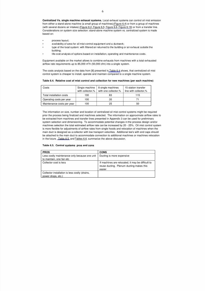
7/18/2019 Ventilation Guide
http://slidepdf.com/reader/full/ventilation-guide 61/223
6
Centralized Vs. single machine exhaust systems. Local exhaust systems can control oil mist emission
from either a stand-alone machine (a small group of machines) (Figure 6.4) or from a group of machines
(with several dozens air intakes) (Figure 6.2, Figure 6.5, Figure 6.6, Figure 6.19) or from a transfer line.
Considerations on system size selection: stand-alone machine system vs. centralized system is made
based on:
• process layout;
• availability of area for oil mist control equipment and a ductwork;
• type of the local system: with filtered air returned to the building or air exhaust outside the
building;
• life-cost analysis of options based on installation, operating and maintenance costs.
Equipment available on the market allows to combine exhausts from machines with a total exhausted
airflow rate requirements up to 85,000 m3 /h (50,000 cfm) into a single system.
The costs analysis based on the data from [8] presented in Table 6.4 shows, that centralized oil mist
control system is cheaper to install, operate and maintain compared to a single machine system.
Table 6.4. Relative cost of mist control and collection for new machines (per each machine)
Costs Single machine
with collector,%
8 single machines
with one collector,%
15 station transfer
line with collector,%
Total installation costs 100 83 115
Operating costs per year 100 35 71
Maintenance costs per year 100 25 50
The information on size, number and location of centralized oil mist control systems might be required
prior the process being finalized and machines selected. The information on approximate airflow rates to
be extracted from machines and transfer lines presented in Appendix 3 can be used for preliminarysystem selection and dimensioning. To accommodate potential changes in the process design and/or
machines selection the total estimated airflow rate can be increased by 20 - 25%. Oil mist control system
is more flexible for adjustments of airflow rates from single hoods and relocation of machines when the
main duct is designed as a collector with low transport velocities. Additional tee's with end caps should
be attached to the main duct to accommodate connection to additional machines or machines relocation
in the future. Table 6.5. and Tables 6.6. summarize the above discussion.
Table 6.5. Central systems pros and cons
PROS CONS
Less costly maintenance only because one unit
to maintain, one fan etc.
Ducting is more expensive
Collector cost is less If machines are relocated, it may be difficult to
reuse ducting. Plenum ducting makes this
easier
Collector installation is less costly (drains,
power drops, etc.)
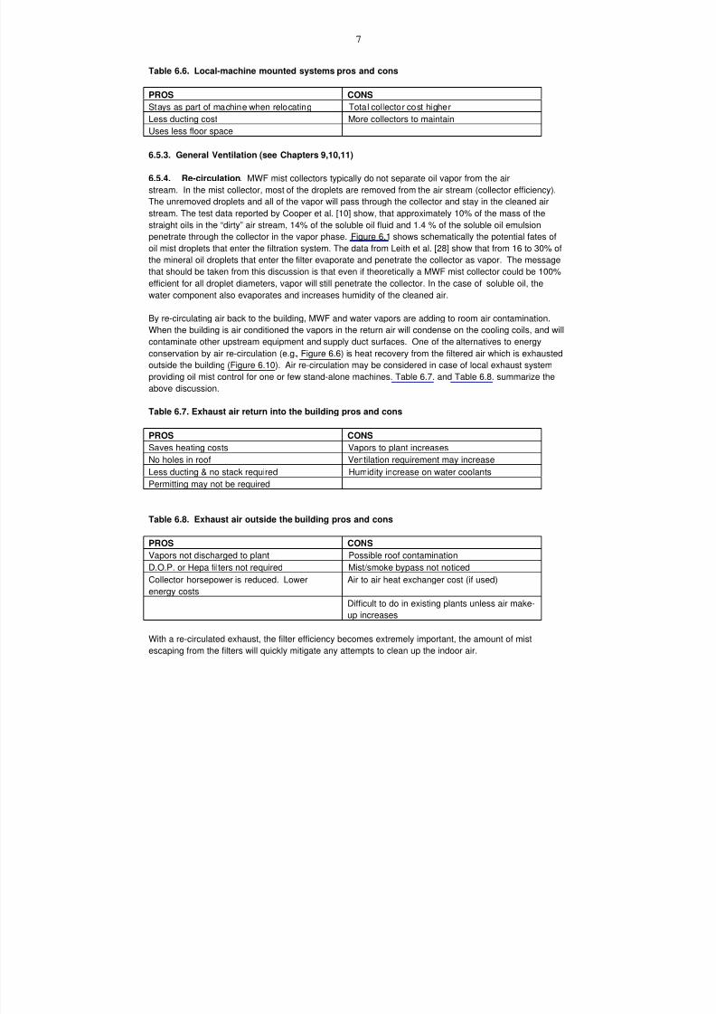
7/18/2019 Ventilation Guide
http://slidepdf.com/reader/full/ventilation-guide 62/223
7
Table 6.6. Local-machine mounted systems pros and cons
PROS CONS
Stays as part of machine when relocating Total collector cost higher
Less ducting cost More collectors to maintain
Uses less floor space
6.5.3. General Ventilation (see Chapters 9,10,11)
6.5.4. Re-circulation. MWF mist collectors typically do not separate oil vapor from the air
stream. In the mist collector, most of the droplets are removed from the air stream (collector efficiency).
The unremoved droplets and all of the vapor will pass through the collector and stay in the cleaned air
stream. The test data reported by Cooper et al. [10] show, that approximately 10% of the mass of the
straight oils in the “dirty” air stream, 14% of the soluble oil fluid and 1.4 % of the soluble oil emulsion
penetrate through the collector in the vapor phase. Figure 6.1 shows schematically the potential fates of
oil mist droplets that enter the filtration system. The data from Leith et al. [28] show that from 16 to 30% of
the mineral oil droplets that enter the filter evaporate and penetrate the collector as vapor. The message
that should be taken from this discussion is that even if theoretically a MWF mist collector could be 100%efficient for all droplet diameters, vapor will still penetrate the collector. In the case of soluble oil, the
water component also evaporates and increases humidity of the cleaned air.
By re-circulating air back to the building, MWF and water vapors are adding to room air contamination.
When the building is air conditioned the vapors in the return air will condense on the cooling coils, and will
contaminate other upstream equipment and supply duct surfaces. One of the alternatives to energy
conservation by air re-circulation (e.g., Figure 6.6) is heat recovery from the filtered air which is exhausted
outside the building (Figure 6.10). Air re-circulation may be considered in case of local exhaust system
providing oil mist control for one or few stand-alone machines. Table 6.7. and Table 6.8. summarize the
above discussion.
Table 6.7. Exhaust air return into the building pros and cons
PROS CONS
Saves heating costs Vapors to plant increases
No holes in roof Ventilation requirement may increase
Less ducting & no stack required Humidity increase on water coolants
Permitting may not be required
Table 6.8. Exhaust air outside the building pros and cons
PROS CONS
Vapors not discharged to plant Possible roof contamination
D.O.P. or Hepa filters not required Mist/smoke bypass not noticed
Collector horsepower is reduced. Lower
energy costs
Air to air heat exchanger cost (if used)
Difficult to do in existing plants unless air make-
up increases
With a re-circulated exhaust, the filter efficiency becomes extremely important, the amount of mist
escaping from the filters will quickly mitigate any attempts to clean up the indoor air.
7/18/2019 Ventilation Guide
http://slidepdf.com/reader/full/ventilation-guide 63/223
8
The difference in efficiency between a 95% efficient filter, and a 99.99% efficient filter when the full
amount of metal working fluids mist generated in a modern manufacturing facility, must be taken into
consideration
6.5.5. Oil mist separation
6.5.5.1. Collector Selection. MWF Mist Collectors are used to remove airborne MWF mist from
an air stream. The mist collector is part of a mist collection system and typically includes the fan and
controls. Mist collectors may be small individual units to handle approximately 1700 m3 /h (1000 cfm) of air
flow or large collectors that may work with either a centralized local exhaust or a general ventilation
system with an airflow rate up to 85,000 m3 /h (50,000 cfm).
To properly select an MWF mist collector the system design should be done first; including type of
enclosure or hooding, approximate number and location of exhaust drops, type of ducting, etc.
If the system design is poor or not considered up front, it may not matter what type of collector is used.
The results could be high maintenance, low efficiency and wasted money. For the information on proper
system design is refer to [2, 6,7,14].
It should be noted that most of collectors are designed to capture aerosols only. It is not cost efficient to
use collectors capable of efficient removal of oil vapors from the air stream.
MWF Mist Collectors are selected based on the following factors:
1. Oil mist concentration.
2. Efficiency requirements.
3. Energy Consumption. All collectors consume energy in order to overcome pressure drop through
the collector. The pressure drop is measured in inches of water. Energy is also consumed
during the cleaning of contaminant from collectors.
4. Maintenance costs. Some collectors can be cleaned on-line, others require off-line cleaning orreplacement of filtration elements.
5. Initial cost
Types of MWF Mist Collectors
Virtually every air filtration device previously used to remove dust or dry particulate may be, and has
been, used to remove MWF aerosols from the exhaust air stream. The specific type of device to be
selected will be based on the user’s criteria in regards to initial cost; operating cost; removal efficiency;
maintenance requirements; and physical space requirements.
Many of the MWF Mist Collectors are multi-stage devices, using several of the mechanisms ofmechanical filtration shown below.
Mechanisms of Mechanical Filtration
There are three different processes responsible for the capture of a particle in a mechanical filter
impingement, interception and diffusion. Usually one prevails in a specific collector, but rarely is it the
exclusive mechanism.

7/18/2019 Ventilation Guide
http://slidepdf.com/reader/full/ventilation-guide 64/223
9
Impingement Filters.
Impingement filters are mechanical filters whose principle mechanism of filtration is impingement. These
filters can be categorized by their configuration: Panel Filters; Roll Filters; Lint Filters (special application
of roll filters); or washable metal-panel filters.
Panel filters are fixed media air filters in which the face velocity and the media velocity are essentially the
same.
ACGIH, Industrial Ventilation Manual [2], Table 4-5. Media velocity Vs. Fiber Size, panel filters are shown
to have a nominal fiber diameter of 25-50 micron, with a media velocity of 250-650 fpm, and a filtration
mechanism of impingement. These filters are at the lower end of the efficiency range.
Extended Surface Filters [32]
Extended surface filters consist of that category in which the filter media area is greater than the filter face
area, (media velocity is less than the face velocity).
The most common method of increasing media area is to pleat the filter media, and to extend the pleated
filter depth. However, other configurations are also used.
Filters designed with extended media surface are desirable for the following reasons:
• Media may perform more efficiently at lower media velocities, especially true for filters
that depend on interception and diffusion as the primary mechanism.
• Media resistance may be too high when the material is used in a flat sheet, typical of high
efficiency media.
• Filter life will be extended due to the increased dust holding capacity of the additionalmedia.
Extended surface filters are characterized by the type of media used, and the configuration into which it is
formed:
Filters using mat type media
• Non-supported pocket (bag)
• Supported cartridge
• Rigid cell type
• Pleated panel
Filters using paper media
• With corrugated separators
• Close-pleated style.
Non-supported Mat Filters
The non-supported mat filter is one of the more popular, high efficiency filters used for general air
filtration. These filters are commonly referred to as “bag filters”, or “pocket filters”.
These style of filters use a rigid face plate to which the filter elements are fastened too, when air is
moving through the bags or pockets, the element expands exposing all of the media to the air stream.
7/18/2019 Ventilation Guide
http://slidepdf.com/reader/full/ventilation-guide 65/223
10
Cartridge Type Filters
There are various configurations of cartridge type filters, one model is the cube filter which is normally
rectangular in shape. Internal support grids may be sewn into the air entering side of the cube, or metal
headers may be used to allow for use in standard HVAC filter housings or filter tracks. Another design of
cartridge filters uses a wire back frame to create several pleats, which increases the media area.
The media for both of these filters is approximately 1” (25.4 mm) thick, and some versions use a dual
media, with different fiber size and density.
Rigid Cell Filters
Rigid cell, deep pleated filters consist of a high efficiency media with backing bonded to a welded wire or
expanded metal grid. The media is pleated and the pleat spacing is maintained by using contour
stabilizers on the upstream and downstream side of the pleats. The pack is then sealed into a galvanized
steel filter frame with diagonal supports, forming a rigid box.
Pleated Panel Filters
Pleated panel filters may be fabricated in depths of 1” (25.4 mm), to 6” (152.4 mm), using a
cotton/polyester blend media with a expanded metal or welded wire support grid. These filters have a
much higher efficiency than glass or plastic mat panel filters while maintaining an acceptable pressure
drop. In addition, pleated panel filters have longer service lives in typical HVAC systems than the glass or
polyester mat configurations.
Paper Media Filters
Most of the paper used in air filtration is made by mixing a slurry of water, filter fibers, and binder. Filter
fibers can be glass, synthetic or natural cellulose materials. After the material is dried, waterproofing and
fungicidal treatment is added. ASHRAE dust spot efficiency for this media can range from 98% to 60%.
Pleated paper filters with corrugated separators are fabricated by pleating the filter media over corrugated
aluminum separators to form a filter pack. The pack is usually sealed in a light –gage metal frame. Face
velocity for these filters may range from 250 – 500 fpm, ( 1.27 – 2.54 m/s).
Close-pleated filters are formed by pleating paper media into a filter pack using string, media ribbons,
adhesive beads, or other methods to maintain pleat spacing. This pack is then sealed into a metal frame
to form rigid panels.
Fabric filters can be effective when new, but their performance decreases over time with liquid loading
[28].
Final Filters
The Institute of Environmental Sciences (IES) defines a HEPA filter as “a throw-away extended media
dry-type filter in a rigid frame, having minimum particle-collection efficiency of 99.97% for 0.3 micrometer
(micron) thermally-generated dioctyl phthalate (DOP) particles or specific alternative aerosol, and a
maximum clean-filter pressure drop of 1.0 in. w.g. when tested at rated air flow capacity”
7/18/2019 Ventilation Guide
http://slidepdf.com/reader/full/ventilation-guide 66/223
11
Cartridge type 95% DOP filters or Hepa Filters are often used as a last or monitoring stage when
discharge is re-circulated to the plant. These should be capable of high removal efficiency down to 0.3-
micron size particles. The 95% DOP filters and the HEPA filter have efficiency 99%+ with a pressure
drop 350-500Pa. Tests reported by Leith et al. [28] demonstrated high efficiency of 95% DOP filters for
all sizes of droplets. Based on these findings, it was concluded that the additional expense of using a true
HEPA filter instead of 95% DOP filter as a final stage seems questionable.
Various Mist Collection Equipment
Centrifugal ( Figure 6.11). Centrifugal impaction filter is a spinning perforated steel drum with internal
blades creates the negative pressure required to pull the mist laden air into the unit. The aerosol is
impacted on the blades in which the particles are forced to coalesce before being thrown by centrifugal
force against the inner surface of the outer casing. Some units are equipped with a foam filter pad to aid
coalescence. Optimum particle size, greater than 10 micron. Liquid is gravity drained.
Spiral Tube Separator (Figure 6.12). This unit consists of a series of separator tubes, each containing a
spiral insert. Mist is separated by centrifugal force and impingement.
Impingement plates (Figure 6.13) . Mist is separated by directional change and impingement of mist
particles. The centrifugal force propels the mist and particulate to the wall of the tube where it forms a
fluid film. Liquid is continuously drained to the bottom of the collector.
Optimum particle size, greater than 10 micron.
Mesh (Figure 6.15). Mesh is available in many materials, including polypropylene and aluminum. The
media may be crimped, knitted or random packed strands. Pressure drop and efficiency depend on the
media and packing density. . The air stream passes through the media , where small droplets coalesce
into larger ones. The density of packing may be varied to achieve the desired efficiency for use as a first,
second, or third stage. To achieve an optimum efficiency, mesh filters require a certain level of liquid
saturation. This can be achieved by adding spraying system. Spraying liquid is injected in adjustable
intervals in order to maintain a certain level of liquid saturation during operation and at the start. meshfilters may be removed and cleaned with a help of a high pressure steam cleaner once or twice a year.
Typical mesh filters are 600 mm x 600 mm (24 inch X 24 inch) and can be 25 mm to 160mm (1 to 6
inches) thick.
Fiber Bed Filters [36]
Fiber Bed Filters are a member of the Fiber Mist Eliminators family, these devices are produced in various
configurations. Generally, randomly oriented glass or polypropylene fibers are densely packed between
reinforcing screens, producing fiber beds varying in thickness usually from 25mm to 75mm (1 to 3 in.),
although thicker beds can be produced. Units with efficiencies as high as 99.99 percent on fine particles
have been developed. [9]
Controlling mechanism - Brownian movement
Superficial velocity, m/s - 0.075 – 0.20
Efficiency, particles > 3 micron - Essentially 100%
Efficiency, particles < 3 micron - 95 – 99+
Pressure drop, cm H2O - 12 – 38 (4.72 – 14.96 in.)
7/18/2019 Ventilation Guide
http://slidepdf.com/reader/full/ventilation-guide 67/223
12
Recent testing at the Department of Environmental Sciences and Engineering, Baity Laboratory for
Environmental Engineering, University of North Carolina, Chapel Hill, NC. provided the following results:
“the collector (fiber bed) removed virtually all mist droplets of soluble oil and synthetic fluid to the limit of
our ability to detect them; the collector removed all mist droplets of mineral oil greater than 0.54 micron
and 99.9% of the mineral oil droplets between 0.27 and 0.54 micron.” [27]
Electrostatic Precipitator
An electrostatic precipitator operates by electrically charging the MWF mist particles and collecting the
charged particles on oppositely charged plates (Figure 6.14). This type of filtration is effective on small,
sub-micron sized particles. Also, the pressure drop through this type of collector is usually the lowest of
the available options, allowing reduced horsepower blowers. Unlike many other collector options, there is
no filter to replace. Disadvantages include the requirement for frequent maintenance. The collection
plates must be cleaned frequently to maintain filtration efficiency and remove film of oil. As oil film grows,
filter efficiency is reduced. Filtration efficiency varies from 90% to 99% on sub-micron sized particles.
Not recommended for use with combustible or flammable MWF.
Deep Bed Filter (Figure 6.16): The MWF laden air is forced through a layer of porous filter mediaconsisting of fiberglass fibers or plastic granules. The large porous volume of the bulk material operates
as deep-bed filter and ensures high retention of the MWF mist without significant reduction in air
permeability. The separated coolant forms a fluid film, which seeps due to gravity to the bottom of the
bed. Porous filter packing allows to clean filter bed with rinsing nozzles. Cleaning process can be
performed using the nozzles either built-in the collector casing or filter elements can be cleaned outside
the filter casing.
Wet Scrubber – Venturi Type
A wet scrubber separates mist by high velocity impaction at the venturi throat. In the venturi-type scrubber
shown in Figure 6.17, polluted air passes through a venturi-shaped orifice. Scrubbing liquid is added
either at or up stream from the venturi throat. The rapid acceleration of the gas shears the liquid into afine mist, increasing the chance of coolant mist and scrubbing liquid mist impaction. Baffled separators
follow the venturi throat to remove the droplets from the air stream. Also, wet scrubbers allow good
performance in capturing oil vapors. Wet scrubbers can be used with combustible coolants. However,
they are more expensive and have higher energy consumption. This method can be used to collect from
both wet and dry machining.
Multi-stage collectors
Multi-stage devices offer advantages, and disadvantages for the owner:
Advantages: Ability to use filter devices of lower efficiency and cost to reduce
loading and extend service life of the higher efficiency and costdownstream stages.
Disadvantages: Stocking of various types of replacement devices.
Increased cost of monitoring controls for individual stages.
The lifetime of the final filter stage depends upon the cumulative loading it receives, which depends, in
turn, on the performance of the collection stages upstream. For continued long life, the first and second
collection stages must be as efficient as possible.
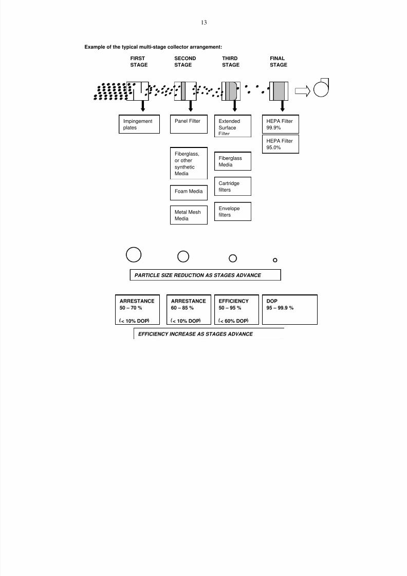
7/18/2019 Ventilation Guide
http://slidepdf.com/reader/full/ventilation-guide 68/223
13
Example of the typical multi-stage collector arrangement:
FIRST
STAGE
SECOND
STAGE
THIRD
STAGE
FINAL
STAGE
Impingement
plates
Panel Filter Extended
Surface
HEPA Filter
99.9%
Fiberglass,or other
synthetic
Media
Metal Mesh
Media
Fiberglass
Media
HEPA Filter
95.0%
Foam Media
Cartridge
filters
Envelope
filters
PARTICLE SIZE REDUCTION AS STAGES ADVANCE
ARRESTANCE
50 – 70 %
< 10% DOP
ARRESTANCE
60 – 85 %
< 10% DOP
EFFICIENCY
50 – 95 %
< 60% DOP
DOP
95 – 99.9 %
EFFICIENCY INCREASE AS STAGES ADVANCE

7/18/2019 Ventilation Guide
http://slidepdf.com/reader/full/ventilation-guide 69/223
14
6.5.5.2. Desirable Collector Features
Housing Construction: Minimum 14 gage steel reinforced to prevent deformation from the negative
pressure. Drain pan area should be welded solid inside and outside.
Inlet Drop-Out: The collector housing should include a low velocity dropout section with an easy open
access door for cleaning.
Access Doors: Include easy to operate door latches and vertical hinges so that door weight is supported
by collector and not maintenance personnel. Mechanically fastened gaskets should be provided (not
glued). Gasket material to be compatible with metal working fluids.
Filter Wash Down: Certain types of collectors can utilize internal flush systems to reduce manual
maintenance. The metal working fluid or sometimes plant water is used for flushing. The internal piping
and housing connection only can be provided for future hook-up and use if necessary. When washdowns
are in use, the collector fan should be off.
Drain Trap: If the collected coolant will be gravity drained it is necessary to provide a trap in the drainline. The trap height should be equal to or greater than the fan suction pressure. A bucket type trap is
recommended with a removable cover to allow cleaning.
Drain Sump: If the collected coolant is to be pumped to an overhead line or reservoir, it is best to include
the required sump, pump and controls as an integral part of the collector.
Fan: For quiet and energy efficient operation, the fan should be a backward inclined airfoil type. It should
be located at the clean air side of the collector and include a housing drain, access door and a V-belt
drive for flexibility in performance.
Sound Control: The desired maximum sound level should be specified by the customer. Typically, fan
discharge sound attenuation is required. A complete fan and motor enclosure with suitable access doorsmay also be beneficial.
Monitoring Equipment: The collector typically should include an hour meter, a motor amperage meter and
pressure differential gages for each filter stage. Filter fault lights or alarms may be included. A more
elaborate system may include a vibration monitor for the fan or a particulate monitor for the collector
discharge.
Fire Protection : When metal working fluids have a low flash point, typically the mineral oils, a fire
protection systems should be included for the collector. Plant, governmental and insurance requirements
must be considered. Methods include using CO2 and water suppression systems, isolating dampers and
explosion relief doors.
6.5.5.3. Static Pressure. The required static pressure for the system must be determined for collector
fan and motor selection. The external static typically ranges from 2 to 6 inches water column depending
on the enclosure, duct velocity and number, length and arrangement of branches. If the discharge is to
the outside, the stack loss must be included.
6.5.5.4. Collector life cycle costs. Initial cost, maintenance including filter replacement costs and
energy costs should be considered to determine the overall cost over time.
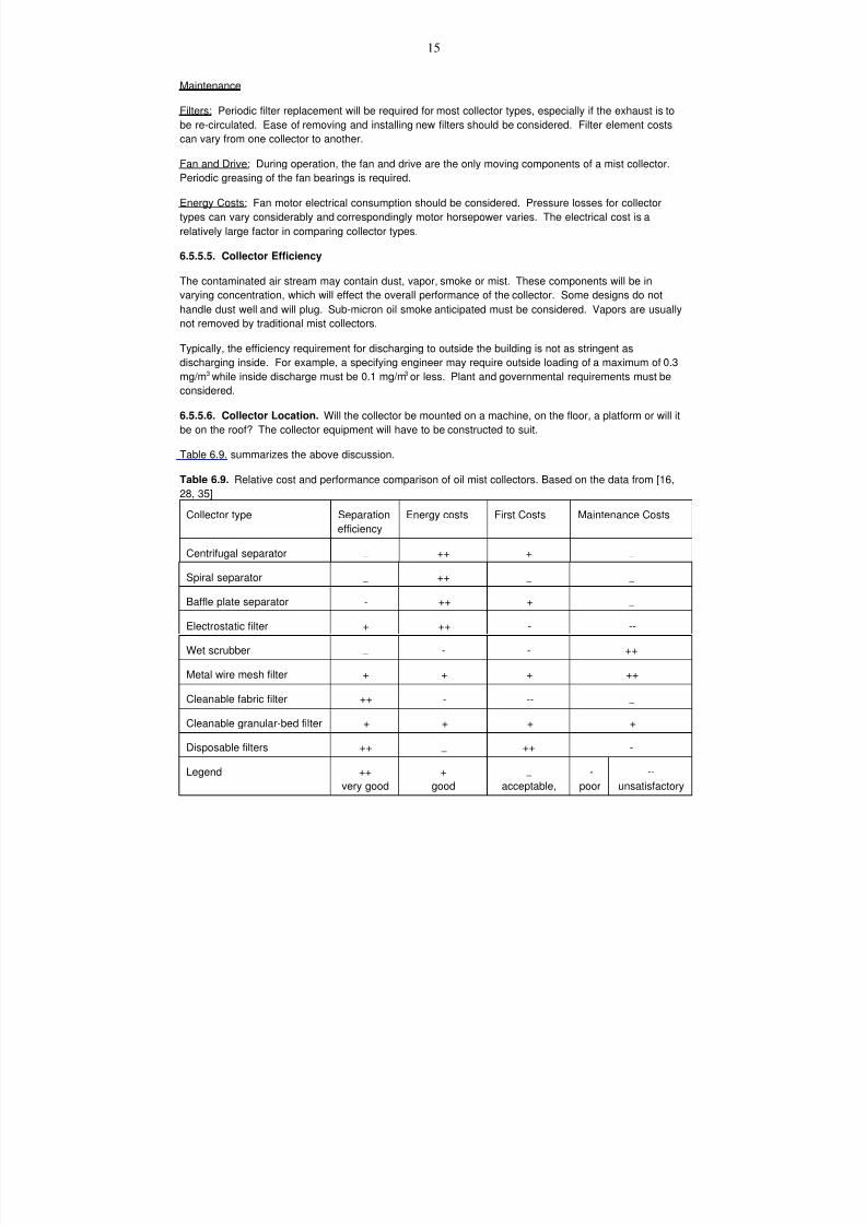
7/18/2019 Ventilation Guide
http://slidepdf.com/reader/full/ventilation-guide 70/223
15
Maintenance
Filters: Periodic filter replacement will be required for most collector types, especially if the exhaust is to
be re-circulated. Ease of removing and installing new filters should be considered. Filter element costs
can vary from one collector to another.
Fan and Drive : During operation, the fan and drive are the only moving components of a mist collector.Periodic greasing of the fan bearings is required.
Energy Costs : Fan motor electrical consumption should be considered. Pressure losses for collector
types can vary considerably and correspondingly motor horsepower varies. The electrical cost is a
relatively large factor in comparing collector types.
6.5.5.5. Collector Efficiency
The contaminated air stream may contain dust, vapor, smoke or mist. These components will be in
varying concentration, which will effect the overall performance of the collector. Some designs do not
handle dust well and will plug. Sub-micron oil smoke anticipated must be considered. Vapors are usually
not removed by traditional mist collectors.
Typically, the efficiency requirement for discharging to outside the building is not as stringent as
discharging inside. For example, a specifying engineer may require outside loading of a maximum of 0.3
mg/m3 while inside discharge must be 0.1 mg/m3 or less. Plant and governmental requirements must be
considered.
6.5.5.6. Collector Location. Will the collector be mounted on a machine, on the floor, a platform or will it
be on the roof? The collector equipment will have to be constructed to suit.
Table 6.9. summarizes the above discussion.
Table 6.9. Relative cost and performance comparison of oil mist collectors. Based on the data from [16,
28, 35]Collector type Separation
efficiency
Energy costs First Costs Maintenance Costs
Centrifugal separator _ ++ + _
Spiral separator _ ++ _ _
Baffle plate separator - ++ + _
Electrostatic filter + ++ - --
Wet scrubber _ - - ++
Metal wire mesh filter + + + ++
Cleanable fabric filter ++ - -- _
Cleanable granular-bed filter + + + +
Disposable filters ++ _ ++ -
Legend ++
very good
+
good
_
acceptable,
-
poor
--
unsatisfactory
7/18/2019 Ventilation Guide
http://slidepdf.com/reader/full/ventilation-guide 71/223
16
References
1. Absolent AB. 1998. Oil-Mist Filter. Product Catalogue.
2. ACGIH. 1998. Industrial Ventilation. A Manual of Recommended Practice. 23 edition. American
Conference of Government Industrial Hygienists. Cincinnati, OH.
3. ACGIH. 1998. Guide to Occupational Exposure Values – 1998. American Conference of
Governmental Industrial Hygienists. Cincinnati, OH.
4. AFS 1996:2. 1996. Occupational Exposure Limit Values. The Swedish National Board of
Occupational Safety and Health.
5. Ameille J, et al. (1995). Respiratory Symptoms, Ventilatory Impairment, and Bronchial Reactivity in
Oil Mist-Exposed Automobile Workers. Am. J. Ind. Med. 27:247-256.
6. ANSI. 1997. Technical Report. ANSI B-11 TR 2-1997. Mist Control Considerations for the Design,
Installation and Use of Machine Tools using Metalworking Fluids.
7. ASHRAE. 1999. ASHRAE Handbook. HVAC Applications. American Society of Heating,
Refrigerating and Air-Conditioning Engineers. Atlanta, GA.
8. Burns, R.E., V.W.Harshfield, W.J. Johnston, R.C. Kramer. 1996. Costs of Oil Mist Control
Installations. The Industrial Metalworking Environment. Symposium Proceedings. November 1995.
AAMA.9. Chemical Engineers’ Handbook, 5th Edition. 1973. New York: McGraw Hill, p. 18-88
10. Cooper, S.J., D. Leith and D. Hands. 1998. The Industrial Metalworking Environment. Symposium
Proceedings. September 1997. AAMA.
11. Eisen E.A. 1995. Healthy Worker Effect in Morbidity Studies. Medicina del Lavoro.
12. Eisen E.A. et al. 1992. Mortality Studies of Machining Fluid Exposure in the Automobile
Industry I: A Standardized Mortality Ratio Analysis. Am. J. Ind. Med. 22:809-824.
13. Ford. 1998. Private communications with Mr. Michael Busch. Ford-Werke. Koeln-Niehl.
14. Ford. 1998. Powertrain Operations - Machine Enclosure Standard. Ford Motor Company.
15. Gannon, P.F.G., Burge, P.S. 1991. A Preliminary Report of a Surveillance Scheme of Occupational
Asthma in the West Midlands. Br. J. Ind. Med. 48(9): 579-582.
16. Gores, St. 1997. Lufttechnische Gesamtkonzerpte für kühlschmierstaffbelastete Industriehallen. VDI Berichte
1326.17. GOST. 1988. General Requirements to the Occupied Zone Air. GOST 12.1.005-88. Moscow.
18. Greaves, I.A., Eisen, E.A., Smith, T.J. et. al. 1995. Respiratory Health of Automobile Workers
Exposed to Metal Working Fluid Aerosols. II: Respiratory Symptoms. Amer. J. Ind. Med.
19. Handte. 1997. Economical and Nonpolluting on Large Scale: Recovery of Oil and Emulsion Mist at Ford
Werke. Private Communications.
20. Helical Dynamics, Inc. 1993. Heli-Flo System. Product Catalogue.
21. Hendy, M..S., Beattie, B.E, Burge P.S. 1985. Occupational Asthma Due to an Emulsified oil mist. Br.
J. Ind. Med. 42: 51-54.
22. INRS. 1985. Guide for Ventilation Practice. Oil Mist Extraction and Processing. Vol.6. INRS, Paris.
23. International Agency for Research on Cancer. 1984. IARC Monographs on the Evaluation of
the Carcinogenic Risks of Chemicals to Humans: Mineral Oils (Lubricant Based oils and Derived
Products), Vol. 33, Lyon, France: IARC, pp. 87-168.
24. Johnston, W.J. 1998. Metal Removal Fluid Mist Control System Considerations. The Industrial
Metalworking Environment. Symposium Proceedings. September 1997. AAMA.
25. Johnston, W.J. and D.W. White. 1996. Machine Enclosure Consideration for Oil Mist Control. The Industrial
Metalworking Environment. Symposium Proceedings. November 1995. AAMA.
26. Kennedy SM et al. (1989). Acute pulmonary responses among automobile workers exposed to
aerosols of machining fluids. Am. J. Ind. Med. 15:627-641.
7/18/2019 Ventilation Guide
http://slidepdf.com/reader/full/ventilation-guide 72/223
17
27. Leith, D. 1998. Long-Term Performance of a Mist Collector. Proceedings of the Symposium “The
Industrial Metalworking Environment: Assessment and Control of Metal Removal Fluids.” September
13-15, 1997. Detroit, MI.
28. Leith, D., P.C. Raynor, M. Boundy and S.J. Cooper. 1996. Performance of Industrial Equipment to
Collect Coolant Mist. The Industrial Metalworking Environment. Symposium Proceedings. November
1995. AAMA.
29. Monroe Environmental Corporation. 1992. Product Catalogue.
30. Monson, R. et al. 1992. Final Report to GM-UAW Occupational Health Advisory Board on Health
Effects of Exposure to Machining Fluids. Harvard School of Public Health, unpublished report.
October 30, 1992 (OSHA Docket No. 372, Ex. No. 2-7A).
31. NIOSH. 1998. Occupational Exposure to Metalworking Fluids. Criteria for a Recommended
Standard. US DOH.
32. National Air Filter Association. 1993. NAFA Guide to Air Filtration, First Edition.
33. Nisi, D. Entwicklung der Lufttechnik in Industriehallen mit mechanischer Fergung und Gießerei. VDI
Berichte 1326.
34. OSHA. 1998. Metalworking Fluids. www. page.
35. Paul, H. 1997. Erfahrungsbericht über KSS in der Automobilindustrie. Aktuelle Entwicklungen in der
zespanended und umformenden Industrie. Symposium'97. Keller Lufttechnik.36. Perry’s Chemical Engineers Handbook, 6th Edition. 1984. Eds.: R.H.Perry and C.H. Chilton. New
York. McGraw Hill.
37. Plymovent. 1998. Clean Fresh Air. Consultants Handbook. Industrial Products. Sweden: Plymovent
AB.
38. Robertson, A.S., Weir, D.C., Burge, P.S. 1988. Occupational Asthma Due to Oil Mists. Thorax 43:
200-205.
39. Raynor, P.C. and D. Leith. 1998. Processes Affecting Performance of Mist Collection Filters. The
Industrial Metalworking Environment. Symposium Proceedings. September 1997. AAMA.
40. Rosenman, K.D., Reilly, M.J. 1993. Annual Report on Occupational Asthma in Michigan. Michigan
Department of Public Health, Bureau of Occupational Health, Lansing, Michigan.
41. Rotimi C, et al. 1993. Retrospective Follow-up Study of Foundry and Engine Plant Workers. Am. J.
Ind. Med. 24:485-498.42. Sprince, N., et al. (1994) Chapter 34, Oils and Related Petroleum Derivatives, in Textbook of Clinical
Occupational and Environmental Medicine, Rosenstock, L. and Cullen, M.R., eds., Saunders, 1994.
43. Tolbert, P.E. et al. 1992. Mortality Studies of Machining-Fluid Exposure in the Automobile Industry II:
Risks Associated With Specific Fluid Types. Scand. J. Work Environ. Health 18:351-360.
44. Turchan, M.C. 1996. Dry Machining: The Ultimate Solution. The Industrial Metalworking Environment.
Symposium Proceedings. November 1995. AAMA.
45. VDI. 1997. Air Conditioning Systems for Factories. VDI 3802. VDI – Richtlinien. D_sseldorf: VDI.
46. Vena, J.E. et al. 1985. Mortality of Workers in an Automobile Engine and Parts Manufacturing
Complex. Br J Ind. Med. 42:85-93.
47. VVS. 1997. Olieudskillere. Industrie-Ventilation. VVS danvac special. No. 7. Teknisk Forlag A/S.
48. Woody, A. 1997. Ventilation Systems Applied to Automotive Manufacturing. Proceedings of the 5th
International Symposium on Ventilation for Contaminant Control "Ventilation'97". September, 1997. Ottawa.
7/18/2019 Ventilation Guide
http://slidepdf.com/reader/full/ventilation-guide 73/223
18
Appendix 1. Machine types.
Various machines are defined by their transport style such as:
Pallet
Transfer - These machines clamp a part into a fixture that is moved through the
machine using push bars, conveyors, etc.
Lift
and Carry - These machines lift the part out of fixed fixtures at each station and
transfer it to the next station where it is lowered into the next fixture and clamped
into place.
Dial
Transfer - These machines use rotary tables with the work stations located either
on the outside or inside of the turning table. The parts are loaded into
fixtures that move as the table moves from station to station. Often the
load and unload stations are the same station and often these machines
are manually loaded since parts are usually smaller.
General Use Machines - These machines are designed to perform a specific operation
and are either manually operated or have some type of computer controls.
Turning
Machines - These machines use sharpened steel or carbide tools and apply them
from a tool holder mounted on a movable machine component (saddle) to a
turning part. Lathes are classified by their size (swing and stroke), whether the
saddle moves horizontally or vertically, and whether they are manual or CNC
controlled. Manual lathes are often further classified as standard, engine, or
turret types. CNC machines often carry a designation of HTL or VTL (horizontal
or vertical turning lathes or centers). Screw machines are also turning machines
that feed bar stock into the machine and cut it off from the bar after the part is
machined.
Machining Centers
Milling Machines - These machines hold the part on a movable table and use a rotating tool
to cut the part. They are classified by the table and spindle maximum strokes
(part envelope), vertical or horizontal movement of the spindle, and manual or
CNC controls. Manual machines, (milling machines) are typical found in tool-
rooms for non-production applications and are usually very open.
Gear cutters are a type of automated milling machine.
CNC machines (machining centers) are usually enclosed around the perimeter
but often open on the top to allow for movement of the table relative to the
spindle. Machining Center manufacturers use different designations but oftenrefer to their machines as VMC’s or HMC’s (vertical or horizontal machining
centers).
Grinders - These machines all apply a high speed rotating abrasive wheel to a
slower moving part to remove material by gouging out small pieces of the
part with the imbedded grit particles in the wheel. These machines are
classified by the type of surface they are grinding, the orientation of the
7/18/2019 Ventilation Guide
http://slidepdf.com/reader/full/ventilation-guide 74/223
19
wheel, and whether they have manual or CNC controls. Several different types
exist:
OD Grinders - remove material from the outside diameter of a
rotating part. These can be center or center-less
type machines.
Center machines hold the part in a chuck and rotate it with the
wheel applied to the outside.
Center-less grinders wedge the part between the grinding wheel
and a regulating wheel that is set at a specific distance from the
grinding wheel.
These machines can be either through feed or plunge type. In
through feed the part simply rotates and works its way along the
slightly angled grinding wheel and falls out the back-side of the
machine.
In a plunge grinding application the part likely cannot be feed
through because of its configuration, so it is held in place with a
stop and the grinding wheel turns and abrades it to size.
ID Grinders - remove the material from the inside diameter of a part. These
wheels are generally mounted on a mandrel and spin inside the
part to size it, Jig Bores are a special type of ID grinder.
Surface
Grinders - typically hold the part on a movable table and apply
a fixed position wheel in intermittent strokes of the table. Oftenthese are manual machines used for gang machining of like
parts.
Rotary
Grinders - use a rotating table to move the part under and out from under a
horizontally mounted grinding -wheel.
Tool Cutter
Grinders - are grinders designed for multiple axis work on a part and are
generally used for making cutting tools.
Flute grinders are a special tool cutter grinder designed for flute
work.
Form
Grinders - are grinders that have a specific form designed into the wheel.
They can be OD, surface, or tool cutter types.
Broaching,
Hobbing,

7/18/2019 Ventilation Guide
http://slidepdf.com/reader/full/ventilation-guide 75/223
20
Sawing - These operations used toothed tools for lower speed metal
removal applications where the tool is passed over the part and
cuts its way through. These operate at relatively lower speeds.
Non-Traditional Machines - These are machines that perform metal removal or metal forming
operations in a non-traditional way.
These include Electrical Discharge Machines (EDM’s), polishers,
brushes, burnishers, knurling machines, and Water Jet Machining .
Forming Machines - These machines shape the part by forcing the
material into some type of die or mold. Again, both special purpose
machines and general use types are common. Often these machines are
grouped in a line or cell configuration in order to do several different
operations on the same part.
Hot Forging Machines - These machines stamp hot material into a series
of forming and/or trim dies. Since this is high temperature operation,
there is a lot of mist generated. Some is from the parting fluid used tokeep the part from sticking in the die.
Often a secondary operation is used to quench the hot part for easier
handling or to improve the material characteristics.
This is a high mist generator, but can present plugging problems with the
higher temperatures and the possibility of burnt insoluble particles.
Cold Forming Machines - These machines take the material at its ambient
temperature, and force it into dies that gradually shape the part to the
finished design. There are several types of these machines.
Stamping Presses - form flat sheets of material into various shapes.
They also use a separating fluid and can produce smoke and lowerquantities of mist.
Cold Headers - are a special type of forming machine that makes smaller
parts from a wire stock material. The wire size can be either compressed
into a smaller or different configuration. Mist and smoke generation is
high due to the temperature increase in the cold working of the material
and the high speed of the rams
.
Bolt Makers - are a special type of cold header that combines traditional
machining with the cold forming technology.
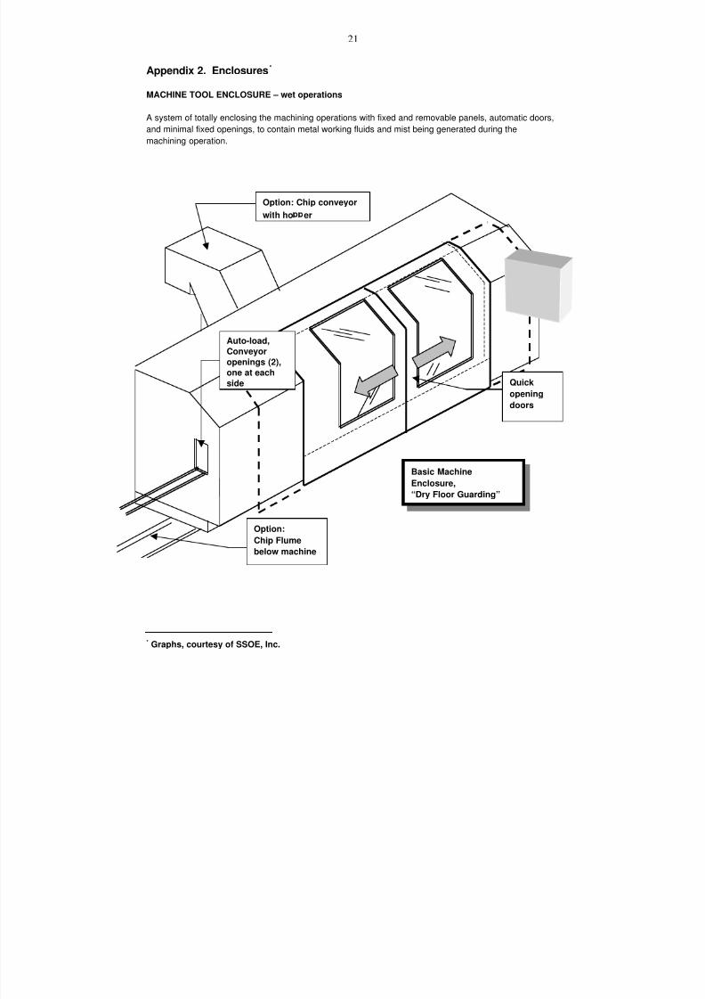
7/18/2019 Ventilation Guide
http://slidepdf.com/reader/full/ventilation-guide 76/223
21
Appendix 2. Enclosures*
MACHINE TOOL ENCLOSURE – wet operations
A system of totally enclosing the machining operations with fixed and removable panels, automatic doors,
and minimal fixed openings, to contain metal working fluids and mist being generated during the
machining operation.
* Graphs, courtesy of SSOE, Inc.
Option:
Chip Flumebelow machine
Option: Chip conveyor
with ho er
Auto-load,
Conveyor
openings (2),
one at each
side Quick
opening
doors
Basic Machine
Enclosure,
“Dry Floor Guarding”
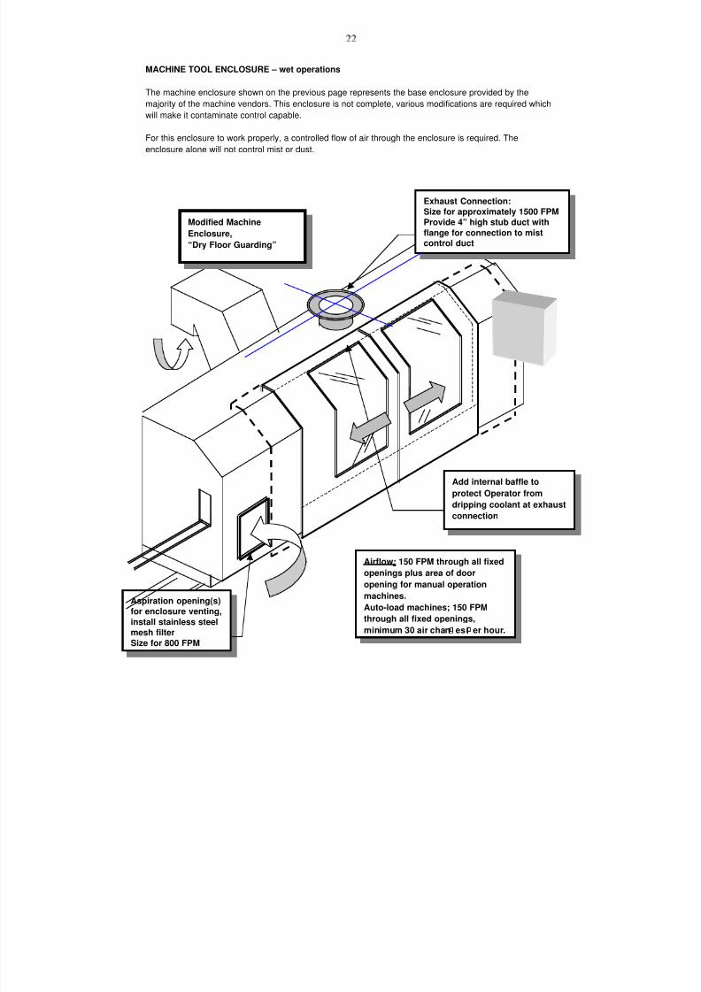
7/18/2019 Ventilation Guide
http://slidepdf.com/reader/full/ventilation-guide 77/223
22
MACHINE TOOL ENCLOSURE – wet operations
The machine enclosure shown on the previous page represents the base enclosure provided by the
majority of the machine vendors. This enclosure is not complete, various modifications are required which
will make it contaminate control capable.
For this enclosure to work properly, a controlled flow of air through the enclosure is required. The
enclosure alone will not control mist or dust.
Aspiration opening(s)
for enclosure venting,
install stainless steel
mesh filter
Size for 800 FPM
Exhaust Connection:
Size for approximately 1500 FPM
Provide 4” high stub duct with
flange for connection to mistcontrol duct
Add internal baffle to
protect Operator from
dripping coolant at exhaust
connection
Airflow; 150 FPM through all fixed
openings plus area of door
opening for manual operation
machines.
Auto-load machines; 150 FPM
through all fixed openings,
minimum 30 air chan es er hour.
Modified Machine
Enclosure,
“Dry Floor Guarding”

7/18/2019 Ventilation Guide
http://slidepdf.com/reader/full/ventilation-guide 78/223
23
MACHINE TOOL ENCLOSURE – wet operations
Side View
Exhaust duct connection
Size for a velocity of 1500 to 2000
FPM.
Internal baffle over exhaust opening, toprevent coolant spray or chips from
being thrown directly into the exhaust,
and to prevent liquid on the inside
surface of the duct from draining down
onto the operator during maintenance.
Adjust space to keep
velocity of 1000 to
Transition to fit within machine
tool, and reduce velocity to
1000 to 1500 FPM.
Coolant/Chip
flume below
machine, or
individual chip
conveyor.
Sliding door
Slope for coolant and
chip removal
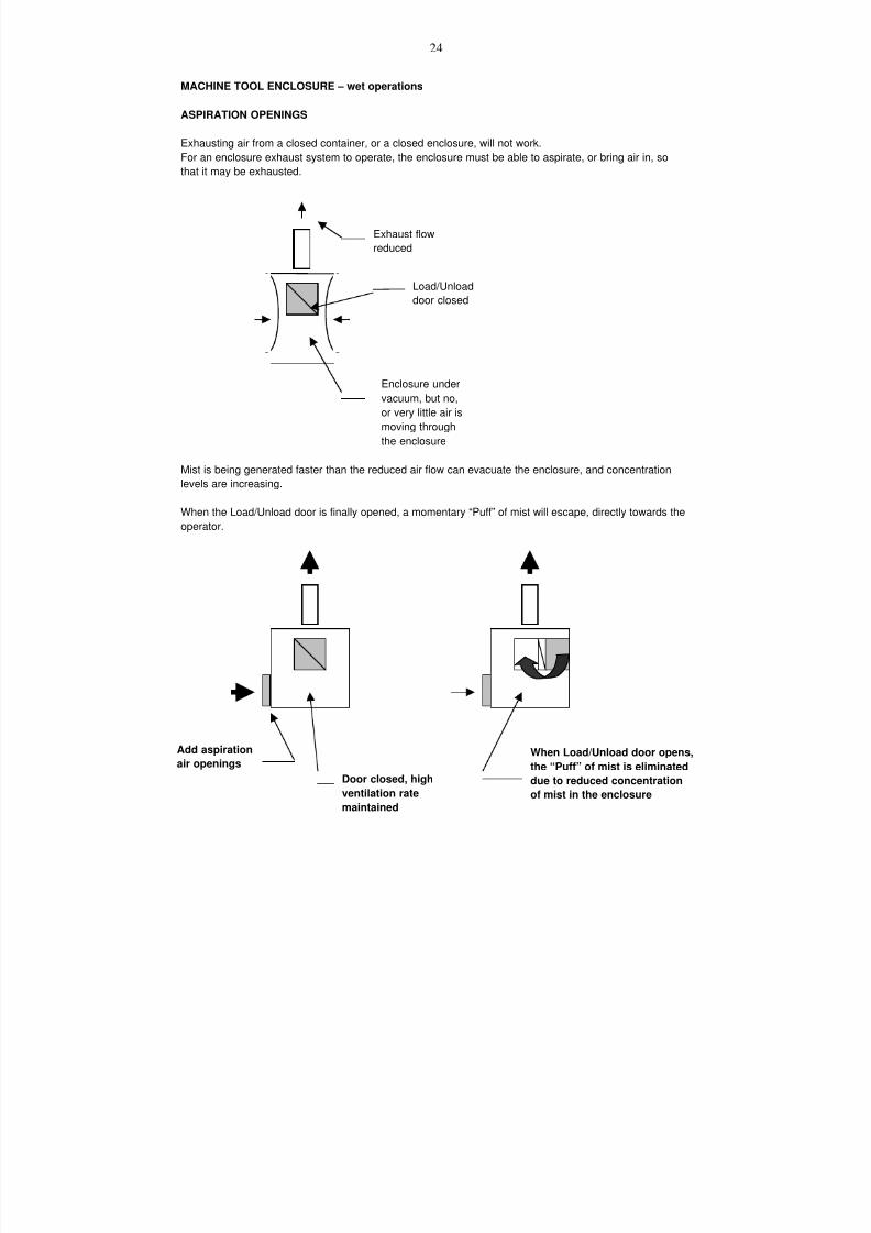
7/18/2019 Ventilation Guide
http://slidepdf.com/reader/full/ventilation-guide 79/223
24
MACHINE TOOL ENCLOSURE – wet operations
ASPIRATION OPENINGS
Exhausting air from a closed container, or a closed enclosure, will not work.
For an enclosure exhaust system to operate, the enclosure must be able to aspirate, or bring air in, so
that it may be exhausted.
Mist is being generated faster than the reduced air flow can evacuate the enclosure, and concentration
levels are increasing.
When the Load/Unload door is finally opened, a momentary “Puff” of mist will escape, directly towards the
operator.
Exhaust flow
reduced
Load/Unload
door closed
Enclosure under
vacuum, but no,
or very little air is
moving through
the enclosure
Add aspiration
air openings
Door closed, high
ventilation rate
maintained
When Load/Unload door opens,
the “Puff” of mist is eliminated
due to reduced concentration
of mist in the enclosure
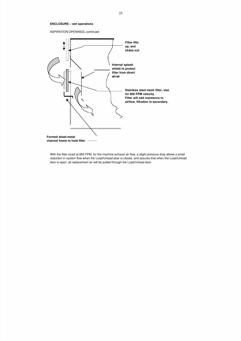
7/18/2019 Ventilation Guide
http://slidepdf.com/reader/full/ventilation-guide 80/223
25
ENCLOSURE – wet operations
ASPIRATION OPENINGS, continued
With the filter sized at 800 FPM, for the machine exhaust air flow, a slight pressure drop allows a small
reduction in system flow when the Load/Unload door is closed, and assures that when the Load/Unload
door is open, all replacement air will be pulled through the Load/Unload door.
Filter lifts
up, andslides out
Internal splash
shield to protect
filter from direct
s ra
Formed sheet-metalchannel frame to hold filter
Stainless steel mesh filter, size
for 800 FPM velocity.
Filter will add resistance to
airflow, filtration is secondary.

7/18/2019 Ventilation Guide
http://slidepdf.com/reader/full/ventilation-guide 81/223
26
MACHINE TOOL ENCLOSURE – wet operations
Load/Unload
doors o en

7/18/2019 Ventilation Guide
http://slidepdf.com/reader/full/ventilation-guide 82/223
27
MACHINE TOOL ENCLOSURE – wet operations
Chip
Hopper
Removable
cover on
chip
conveyor
Chip conveyor
Normalexhaust
volume based
on 150 FPM
velocity
through
discharge
opening Machine
If chips and residual coolant generate an
odor, a canopy hood with side curtains
may be required.
Base airflow on open area between
cano hood and curtains at 150 FPM
Chip conveyor
discharge exhaust
through machine
enclosure.
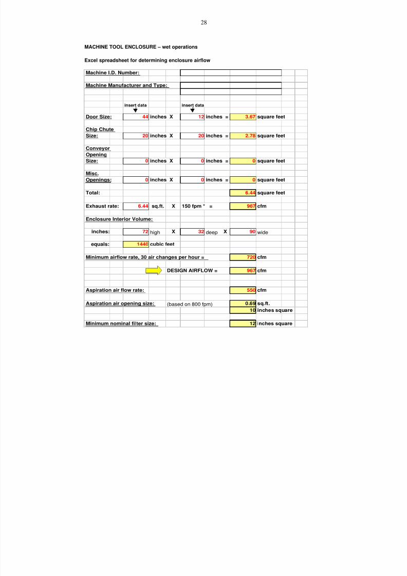
7/18/2019 Ventilation Guide
http://slidepdf.com/reader/full/ventilation-guide 83/223
28
MACHINE TOOL ENCLOSURE – wet operations
Excel spreadsheet for determining enclosure airflow
Machine I.D. Number:
Machine Manufacturer and Type:
insert data insert data
Door Size: 44 inches X 12 inches = 3.67 square feet
Chip Chute
Size: 20 inches X 20 inches = 2.78 square feet
Conveyor
OpeningSize: 0 inches X 0 inches = 0 square feet
Misc.
Openings: 0 inches X 0 inches = 0 square feet
Total: 6.44 square feet
Exhaust rate: 6.44 sq.ft. X 150 fpm * = 967 cfm
Enclosure Interior Volume:
inches: 72 high X 32 deep X 90 wide
equals: 1440 cubic feet
Minimum airflow rate, 30 air changes per hour = 720 cfm
DESIGN AIRFLOW = 967 cfm
Aspiration air flow rate: 550 cfm
Aspiration air opening size: (based on 800 fpm) 0.69 sq.ft.
10 inches square
Minimum nominal filter size: 12 inches square
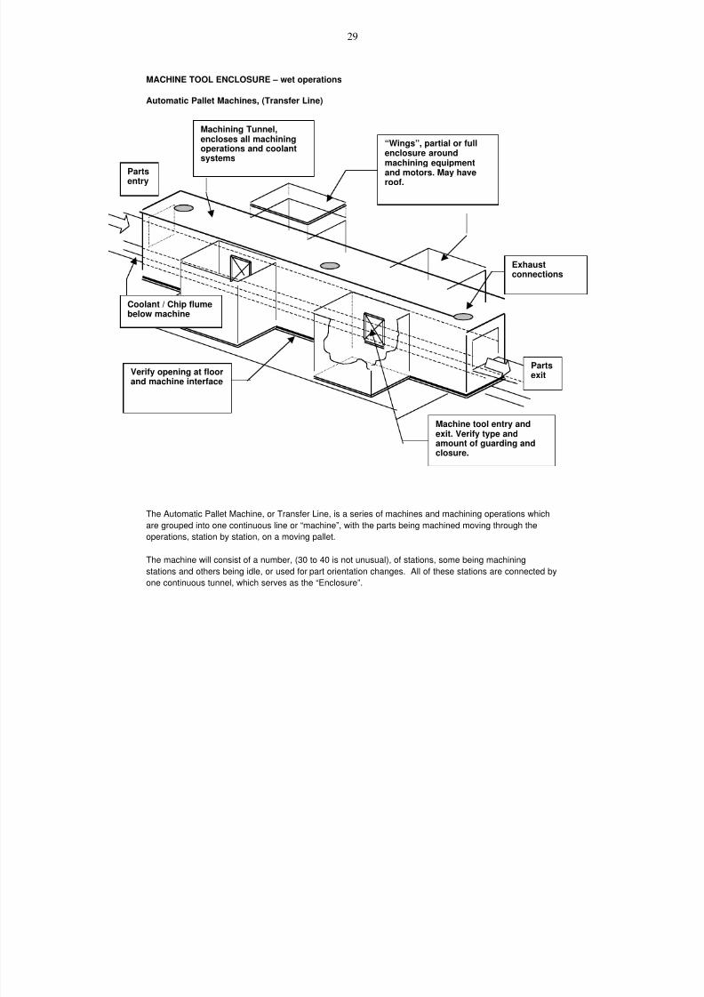
7/18/2019 Ventilation Guide
http://slidepdf.com/reader/full/ventilation-guide 84/223
29
MACHINE TOOL ENCLOSURE – wet operations
Automatic Pallet Machines, (Transfer Line)
The Automatic Pallet Machine, or Transfer Line, is a series of machines and machining operations which
are grouped into one continuous line or “machine”, with the parts being machined moving through the
operations, station by station, on a moving pallet.
The machine will consist of a number, (30 to 40 is not unusual), of stations, some being machining
stations and others being idle, or used for part orientation changes. All of these stations are connected by
one continuous tunnel, which serves as the “Enclosure”.
Partsentry
“Wings”, partial or fullenclosure aroundmachining equipmentand motors. May haveroof.
Machining Tunnel,encloses all machiningoperations and coolantsystems
Machine tool entry andexit. Verify type andamount of guarding andclosure.
Verify opening at floorand machine interface
Coolant / Chip flumebelow machine
Exhaustconnections
Partsexit

7/18/2019 Ventilation Guide
http://slidepdf.com/reader/full/ventilation-guide 85/223
30
MACHINE TOOL ENCLOSURE – wet operations
Automatic Pallet Machines, (Transfer Line)
The enclosure will be kept under negative pressure by ventilation systems. The exhaust airflow rate
must be sufficient to prevent contaminants from escaping from the enclosure. The design of the
enclosure should prevent short circuits of incoming air to the duct system without affecting the collection
of contaminants.
Care should be exercised in the selection of the duct connection location to prevent chips and coolant
entry. The intent is to only collect light contaminants and keep the enclosure under a negative pressure.
Enclosures should be designed with tapered duct entry in order to minimize duct entry velocity and
losses. Design the enclosure with internal chip or spray baffles, if required, to contain over-spray.
High velocity duct entries or the location of baffles that would restrict duct take-off area, and create the
same affect as a high velocity duct entry should be avoided because they may entrain of chips and
coolant into the duct system. Suggested duct entry velocities would be approximately 5 m/s (1000 fpm) or
less for materials such as cast iron steel or aluminum. Lower velocities may be required for less dense
material such as plastic.
Enclosure inlet velocities recommended to contain mist within the enclosure, may vary from 0.5 m/s (100
fpm) [16] to 0.75 m/s (150 fpm). [24]
Parts
entry
Station # 01
“Load”
Station # 03
“machining”
Station # 05
“Idle”
Station # 07
“machining”
Station # 08
“Idle”
Station # 09
“Un-Load”
Station # 02
“Idle”
Station # 04
“Idle”
Station # 06
“Positioning”
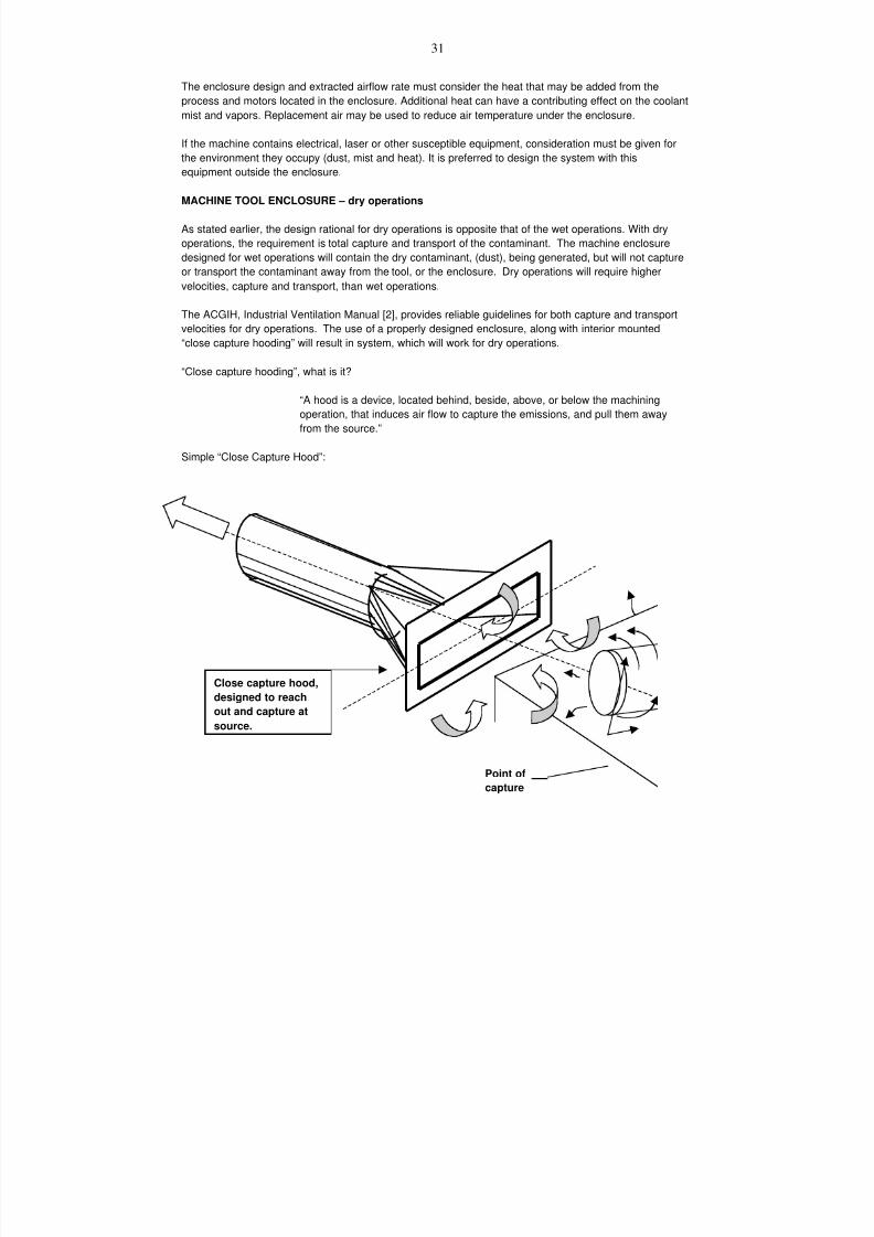
7/18/2019 Ventilation Guide
http://slidepdf.com/reader/full/ventilation-guide 86/223
31
The enclosure design and extracted airflow rate must consider the heat that may be added from the
process and motors located in the enclosure. Additional heat can have a contributing effect on the coolant
mist and vapors. Replacement air may be used to reduce air temperature under the enclosure.
If the machine contains electrical, laser or other susceptible equipment, consideration must be given for
the environment they occupy (dust, mist and heat). It is preferred to design the system with this
equipment outside the enclosure.
MACHINE TOOL ENCLOSURE – dry operations
As stated earlier, the design rational for dry operations is opposite that of the wet operations. With dry
operations, the requirement is total capture and transport of the contaminant. The machine enclosure
designed for wet operations will contain the dry contaminant, (dust), being generated, but will not capture
or transport the contaminant away from the tool, or the enclosure. Dry operations will require higher
velocities, capture and transport, than wet operations.
The ACGIH, Industrial Ventilation Manual [2], provides reliable guidelines for both capture and transport
velocities for dry operations. The use of a properly designed enclosure, along with interior mounted“close capture hooding” will result in system, which will work for dry operations.
“Close capture hooding”, what is it?
“A hood is a device, located behind, beside, above, or below the machining
operation, that induces air flow to capture the emissions, and pull them away
from the source.”
Simple “Close Capture Hood”:
Close capture hood,
designed to reach
out and capture at
source.
Point of
capture

7/18/2019 Ventilation Guide
http://slidepdf.com/reader/full/ventilation-guide 87/223
32
DRY OPERATIONS
For dry machining operations, a system of close capture hooding may be better than a full enclosure.
When close capture hooding is properly designed and installed, the necessity of a full enclosure is gone.
In fact, the enclosure may hamper, more than help the control of contaminants due to restriction of space
available to install hoods.
Duct velocity must increasefor dust transport, andtransition section is notrequired.
Baffle plate not
required
Optional, flex duct withsmall close capture hoodinside enclosure atsource.
Internal surfaces to besloped to prevent buildup of material
FOR DRY MACHININGOPERATIONS, A SYSTEM OFCLOSE CAPTURE HOODINGMAY BE BETTER THAN AFULL ENCLOSURE

7/18/2019 Ventilation Guide
http://slidepdf.com/reader/full/ventilation-guide 88/223
33
HOOD TYPES
Enclosing Hoods Exterior Hoods
Enclosing hoods are those Exterior hoods are those which
which completely or partially are located adjacent to an emission source
enclose the process or contaminant without enclosing it.
generation point.
FaceVelocity
Source
Source
CaptureVelocity
SlotVelocity
PlenumVelocity
DuctVelocityNomenclature
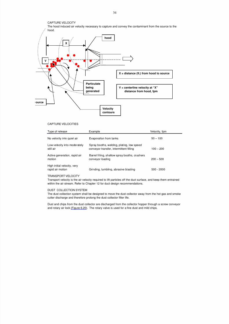
7/18/2019 Ventilation Guide
http://slidepdf.com/reader/full/ventilation-guide 89/223
34
CAPTURE VELOCITY
The hood induced air velocity necessary to capture and convey the contaminant from the source to the
hood.
CAPTURE VELOCITIES
Type of release Example Velocity, fpm
No velocity into quiet air Evaporation from tanks 50 – 100
Low velocity into moderately Spray booths, welding, plating, low speed
still air conveyor transfer, intermittent filling 100 – 200
Active generation, rapid air Barrel filling, shallow spray booths, crushers
motion conveyor loading 200 – 500
High initial velocity, very
rapid air motion Grinding, tumbling, abrasive blasting 500 - 2000
TRANSPORT VELOCITYTransport velocity is the air velocity required to lift particles off the duct surface, and keep them entrained
within the air stream. Refer to Chapter 12 for duct design recommendations.
DUST COLLECTION SYSTEM
The dust collection system shall be designed to move the dust collector away from the hot gas and smoke
cutter discharge and therefore prolong the dust collector filter life.
Dust and chips from the dust collector are discharged from the collector hopper through a screw conveyor
and rotary air lock (Figure 6.20). The rotary valve is used for a fine dust and mild chips.
X
X = distance (ft.) from hood to source
V
V = centerline velocity at “X” distance from hood, fpm
hood
ource
Particulate
beinggenerated
Velocity
contours
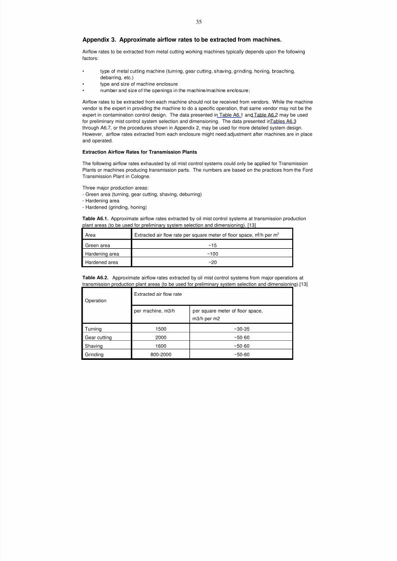
7/18/2019 Ventilation Guide
http://slidepdf.com/reader/full/ventilation-guide 90/223
35
Appendix 3. Approximate airflow rates to be extracted from machines.
Airflow rates to be extracted from metal cutting working machines typically depends upon the following
factors:
• type of metal cutting machine (turning, gear cutting, shaving, grinding, honing, broaching,
debarring, etc.)
• type and size of machine enclosure
• number and size of the openings in the machine/machine enclosure;
Airflow rates to be extracted from each machine should not be received from vendors. While the machine
vendor is the expert in providing the machine to do a specific operation, that same vendor may not be the
expert in contamination control design. The data presented in Table A6.1 and Table A6.2 may be used
for preliminary mist control system selection and dimensioning. The data presented in Tables A6.3
through A6.7, or the procedures shown in Appendix 2, may be used for more detailed system design.
However, airflow rates extracted from each enclosure might need adjustment after machines are in place
and operated.
Extraction Airflow Rates for Transmission Plants
The following airflow rates exhausted by oil mist control systems could only be applied for Transmission
Plants or machines producing transmission parts. The numbers are based on the practices from the Ford
Transmission Plant in Cologne.
Three major production areas:
- Green area (turning, gear cutting, shaving, deburring)
- Hardening area
- Hardened (grinding, honing)
Table A6.1. Approximate airflow rates extracted by oil mist control systems at transmission production
plant areas (to be used for preliminary system selection and dimensioning). [13]Area Extracted air flow rate per square meter of floor space, m3 /h per m2
Green area ~15
Hardening area ~100
Hardened area ~20
Table A6.2. Approximate airflow rates extracted by oil mist control systems from major operations at
transmission production plant areas (to be used for preliminary system selection and dimensioning).[13]
Operation
Extracted air flow rate
per machine, m3/h per square meter of floor space,
m3/h per m2
Turning 1500 ~30-35
Gear cutting 2000 ~50-60
Shaving 1600 ~50-60
Grinding 800-2000 ~50-60
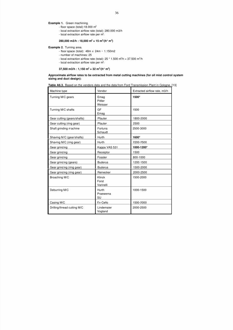
7/18/2019 Ventilation Guide
http://slidepdf.com/reader/full/ventilation-guide 91/223
36
Example 1. Green machining.
- floor space (total):18.000 m2
- local extraction airflow rate (total): 280.000 m3/h
- local extraction airflow rate per m2:
280,000 m3/h : 18,000 m2 = 15 m3/(h* m2)
Example 2. Turning area.
- floor space (total): 48m x 24m ~ 1.150m2
- number of machines: 25
- local extraction airflow rate (total): 25 * 1.500 m3 /h = 37.500 m3 /h
- local extraction airflow rate per m2:
37,500 m3/h : 1,150 m2 = 32 m3/(h* m2)
Approximate airflow rates to be extracted from metal cutting machines (for oil mist control system
sizing and duct design):
Table A6.3. Based on the vendors data and the data from Ford Transmission Plant in Cologne. [13]
Machine type Vendor Extracted airflow rate, m3/h
Turning M/C gears Emag
Pittler
Weisser
1500*
Turning M/C shafts GF
Emag
1500
Gear cutting (gears/shafts) Pfauter 1800-2000
Gear cutting (ring gear) Pfauter 2500
Shaft grinding machine Fortuna
Schaudt
2500-3000
Shaving M/C (gear/shafts) Hurth 1600*
Shaving M/C (ring gear) Hurth 2200-2500
Gear grinding Kappa VAS 531 1000-1200*
Gear grinding Receiptor 1500
Gear grinding Fossler 800-1000
Gear grinding (gears) Buderus 1200-1500
Gear grinding (ring gear) Buderus 1500-2000
Gear grinding (ring gear) Reinecker 2000-2500
Broaching M/C KlinckForst
Varinelli
1500-2000
Deburring M/C Hurth
Praewema
SU
1000-1500
Casing M/C Ex-Cello 1500-2000
Drilling/thread cutting M/C Lindemaier
Vogland
2000-2500
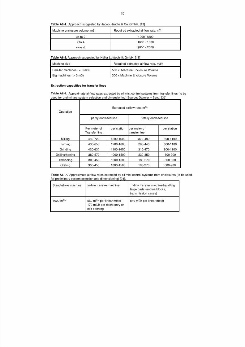
7/18/2019 Ventilation Guide
http://slidepdf.com/reader/full/ventilation-guide 92/223
37
Table A6.4. Approach suggested by Jacob Handte & Co. GmbH. [13]
Machine enclosure volume, m3 Required extracted airflow rate, m3 /h
up to 2 1000 -1200
2 to 4 1600 - 1800
over 4 2000 - 2500
Table A6.5. Approach suggested by Keller Lufttechnik GmbH. [13]
Machine size Required extracted airflow rate, m3/h
Smaller machines ( < 3 m3) 500 x Machine Enclosure Volume
Big machines ( > 3 m3) 300 x Machine Enclosure Volume
Extraction capacities for transfer lines
Table A6.6. Approximate airflow rates extracted by oil mist control systems from transfer lines (to beused for preliminary system selection and dimensioning) Source: Daimler – Benz. [33]
Operation
Extracted airflow rate, m3 /h
partly enclosed line totally enclosed line
Per meter of
Transfer line
per station per meter of
transfer line
per station
Milling 480-720 1200-1600 320-480 800-1100
Turning 430-650 1200-1600 290-440 800-1100
Grinding 420-630 1100-1650 310-470 800-1100
Drilling/honing 380-570 1000-1500 230-350 600-900
Threading 300-450 1000-1500 180-270 600-900
Grating 300-450 1000-1500 180-270 600-900
Table A6. 7. Approximate airflow rates extracted by oil mist control systems from enclosures (to be used
for preliminary system selection and dimensioning) [24].
Stand-alone machine In-line transfer machine In-line transfer machine handling
large parts (engine blocks,
transmission cases)
1020 m3 /h 560 m3 /h per linear meter +
170 m3/h per each entry or
exit opening
840 m3 /h per linear meter

7/18/2019 Ventilation Guide
http://slidepdf.com/reader/full/ventilation-guide 93/223
38
Appendix 4. Coolant types.
Metalworking fluids are needed to create a matrix between the work piece and the tools to improve
machine finish, increase tool life by reducing friction, cool the tool to prevent overheating, inhibit corrosion
and aid in chip removal. Metalworking fluid can be applied to any liquid that flows over or is sprayed on a
piece of metal while the physical configuration is being changed either by tapping, cutting, grinding,
honing, broaching, drawing, or rolling.
Metal working fluids (coolants), used to cool and lubricate the tool and work piece being machined or
ground, are complex mixtures. Characteristics of the various fluid types are as follows:.
• Straight Oil is non-diluted mineral-based oil that has excellent low speed, low clearance operations
requiring high surface finish. They heat up quickly and have a high tendency to mist.
• Soluble oil concentrate is 60 - 90% mineral oil base with extreme pressure additives, corrosion
inhibitors and emulsified additives. Soluble oil is a high water based emulsion that offers good
lubrication and cooling capability. A typical mixture is 90 to 95% water.
• Synthetic fluid contains no mineral oil and has a high water content with corrosion inhibitors,
surfactants and extreme pressure additives. Their use ranges from grinding to moderate/heavy
machining operation if synthetic lubricants are present. They offer good corrosion control with bettercooling capacities and other fluids.
• Semi-synthetic is usually a combination of the above - thus, the terminology semi-synthetic. The
concentrate will have 2 - 30% soluble oil. They offer good lubrication for moderate to heavy
machining applications and better cooling and wetability than soluble oils.
As can be seen the oil comes from two types - mineral and synthetic. The mineral oils are napthenic and
paraffinic hydrocarbons refined from crude oil. Synthetic oils are hydrocarbon based, poluglycol or ester
oil poloalphaolefins. Major additives to these solutions include the following:
• Emulsifiers - stabilizes coolants by preventing oil droplets from coalescing
• Corrosion inhibitors - alkaline and alkanolamine salts to inhibit oil evaporation
• Polar additives (various oils) - to reduce friction and improve wetability• Extreme pressure additives - chloride, phosphorus and sulfur compounds to reduce welding of metals
during heavy machining
• Biocides - to control bacteria, fungi, yeast and mold
All coolants require a proper balance of their additives and the control of foreign elements for good
performance and minimal generation of air contaminants. Water hardness can be a problem with the
soluble oils since the emulsion can split forming a precipitate that can collect on parts and clog filters.
Immiscible liquids are obvious contaminants in coolant. Water may be undesirable in an oil lubricant just
as foreign oil (tramp oil, which is any foreign undesirable oil, grease or floating contaminant found in a
water base coolant) harms the performance of water base coolants.
Tramp oils in many water base coolants are in the system because of hydraulic leaks and the
accumulation of lube oils or protective oil films carried in on raw materials. Also, oils or chemicals can be
carried over from the previous operations. In addition, there are other types of floating contaminants,
such as graphite in cast iron alloys and metallic soaps (“scum”) generated with varying degrees of
efficiency, depending upon the application. Inverted emulsions are another type of contaminant found
floating on the surfaces of a reservoir. An inverted emulsion is an oil particle, which surrounds a water
particle that is not totally mixed in the emulsified state. The oil particle will pick up debris and
contaminants from the system and appear as a black, oily gel. These are often mistaken for tramp oil.
7/18/2019 Ventilation Guide
http://slidepdf.com/reader/full/ventilation-guide 94/223
39
Tramp oils can be controlled by centrifuges or other separating devices and efforts should be made to
keep the concentration below five percent.
Some synthetic and semi-synthetic coolants use amines. Amines are known to cause headaches. Verify
if the coolants have amines. A good source for this is the MSDS sheets. If a secret indigent is used, a
call to the coolant manufacturer should answer the amine question, and any other questions that may
arise.
Soluble oil (typically 95% water, 5% oil emulsions) and other coolants, including those containing lard oil,
tallow, kerosene, and sulfur are subject to producing bacteria initiated odors, requiring periodic or
continuous biocide application. The biocide itself, can be vaporized and become objectionable/sensitizing
to people. There are many types of bacteria found in industrial coolant systems
The MSDS sheets for the coolants and biocides used at the plant should be obtained and evaluated for
compatibility with mist collector components, gasket materials as well as the affects on human exposure,
etc. Review flammability/combustibility of the coolants used. If its flash point is above 300F, the coolant
may require a fire extinguishing system. The MSDS sheet will also provide information regarding any
hazardous to humans by the use of the coolant.
When evaluating the different types of coolants used, verify the volatile organic compounds (VOC) status
of the coolant, and whether a permit will be required for any discharge to the atmosphere. Verify whether
the exhaust from the coolant is suitable for returning to the workspace. Some coolants can be very
odoriferous, and will or could be objectionable to occupants if the air is returned to the workspace. Some
coolants or additives may be carcinogenic, or toxic and may not be suitable for returning the
filtered/treated process exhaust air to the workspace. In general, look for any indoor air quality problem
that might arise from returning the air to the workspace, or verify if any special filtration or other type of air
cleaning/treatment may be required.
There is a relative new additive being developed for the coolant, which is a mist suppressant. This
additive forms long chains of oil molecules keeping the quantity of small oil particles to a minimum. Thelarger oil droplets fall quickly and do not float for long times in the air. These additives currently have a
very short life and thus are quite costly to use.
Be careful of biocides put in coolants, which are used to control bacterial in the coolant.. When dealing
with biocides, as any other contamination source, ensure that the exhaust can be returned to the
workspace. Also verify what ventilation is required where the biocide is added to the coolant. When
biocides are used, look at the MSDS to help define the ventilation requirements.
Foaming is caused by agitated high surface tension fluids which generate hard to break bubbles. Some
surface tension reducing anti-foams are silicones. Confirm the type of anti-foam that may be used and
check with the filter media manufacturer as to the impact on performance of the mist collector. This may
be of greater concern for fiberbed filter type oil mist collectors compared to those that use HEPA filters.There are documented cases where a leaking pump seal, which introduces air into the coolant system,
can cause considerable foaming of the coolant. When evaluating a foaming problem, remember to look
at the coolant pumps, especially for leaks, which can entrain air into the system.
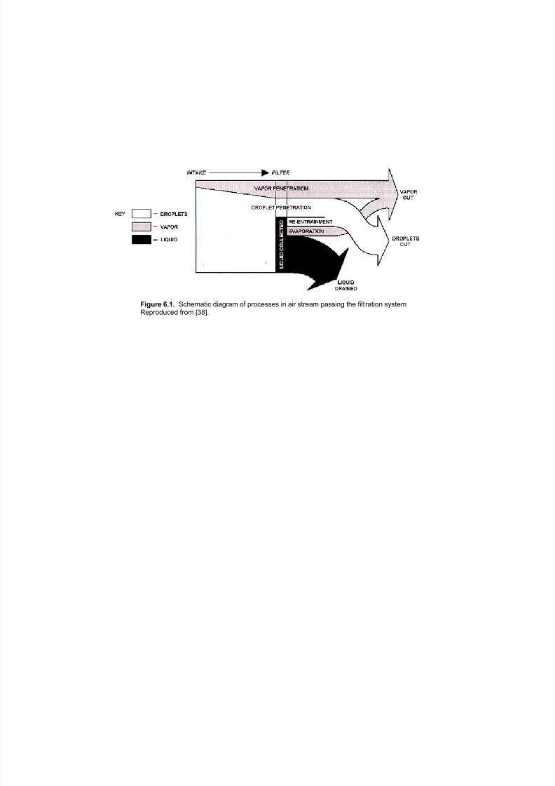
7/18/2019 Ventilation Guide
http://slidepdf.com/reader/full/ventilation-guide 95/223
!"#$%& ()*) "#$%&'()# *)'+,'& -. /,-#%00%0 )1 '), 0(,%'& /'00)1+ ($% .)2(,'()-1 030(%&4%/,-*5#%* .,-& 6789:
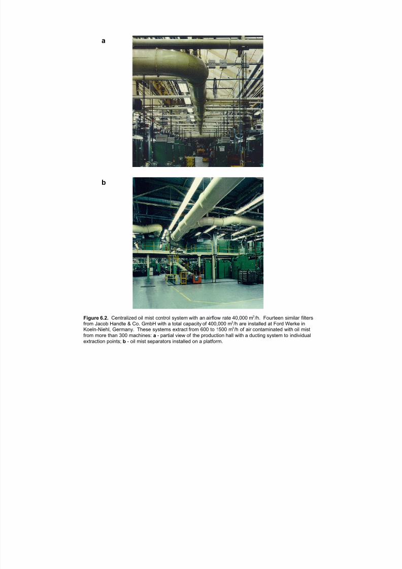
7/18/2019 Ventilation Guide
http://slidepdf.com/reader/full/ventilation-guide 96/223
a
b
Figure 6.2. Centralized oil mist control system with an airflow rate 40,000 m /h. Fourteen similar filters3
from Jacob Handte & Co. GmbH with a total capacity of 400,000 m /h are installed at Ford Werke in3
Koeln-Niehl, Germany. These systems extract from 600 to 1500 m /h of air contaminated with oil mist3
from more than 300 machines: a - partial view of the production hall with a ducting system to individual
extraction points; b - oil mist separators installed on a platform.
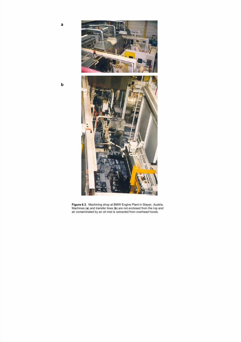
7/18/2019 Ventilation Guide
http://slidepdf.com/reader/full/ventilation-guide 97/223
!
"
#$%&'( *+,+ "#$%&'&'( )%*+ #, -". /'(&'0 12#', &' 3,#4056 78),5	
"#$%&'0) :!; #'< ,5#')=05 2&'0) :"; #50 '*, 0'$2*)0< =5*> ,%0 ,*+ #'<
#&5 $*',#>&'#,0< ?4 #' *&2 >&), &) 0@,5#$,0< =5*> *A05%0#< %**<)9
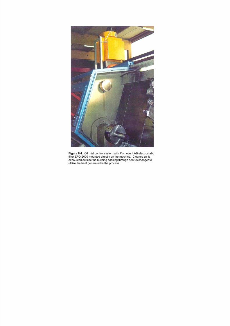
7/18/2019 Ventilation Guide
http://slidepdf.com/reader/full/ventilation-guide 98/223
!"#$%& ()*) !"# %"&' ()*'+)# &,&'-% ."'/ 0#,%)1-*' 23 -#-('+)&'4'"(5"#'-+ 67!89::: %);*'-< <"+-('#, )* '/- %4(/"*-= >#-4*-< 4"+ "&-?/4;&'-< );'&"<- '/- @;"#<"*A B4&&"*A '/+);A/ /-4' -?(/4*A-+ ');'"#"C- '/- /-4' A-*-+4'-< "* '/- B+)(-&&=
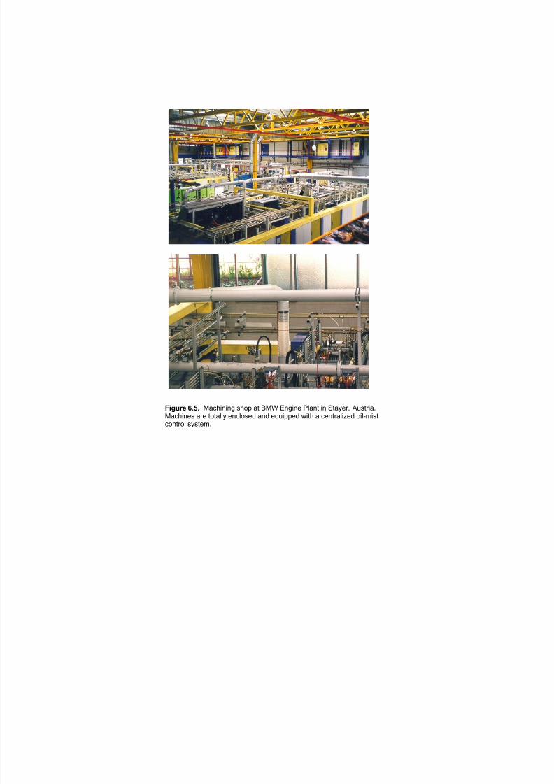
7/18/2019 Ventilation Guide
http://slidepdf.com/reader/full/ventilation-guide 99/223
!"#$%& ()*) !"#$%&%&' )$*+ ", -!. /&'%&0 12"&, %& 3,"4056 78),5%"9!"#$%&0) "50 ,*,"224 0*)0: "&: 0;8%++0: <%,$ " #0&,5"2%=0: *%2>?%),
#*&,5*2 )4),0?9
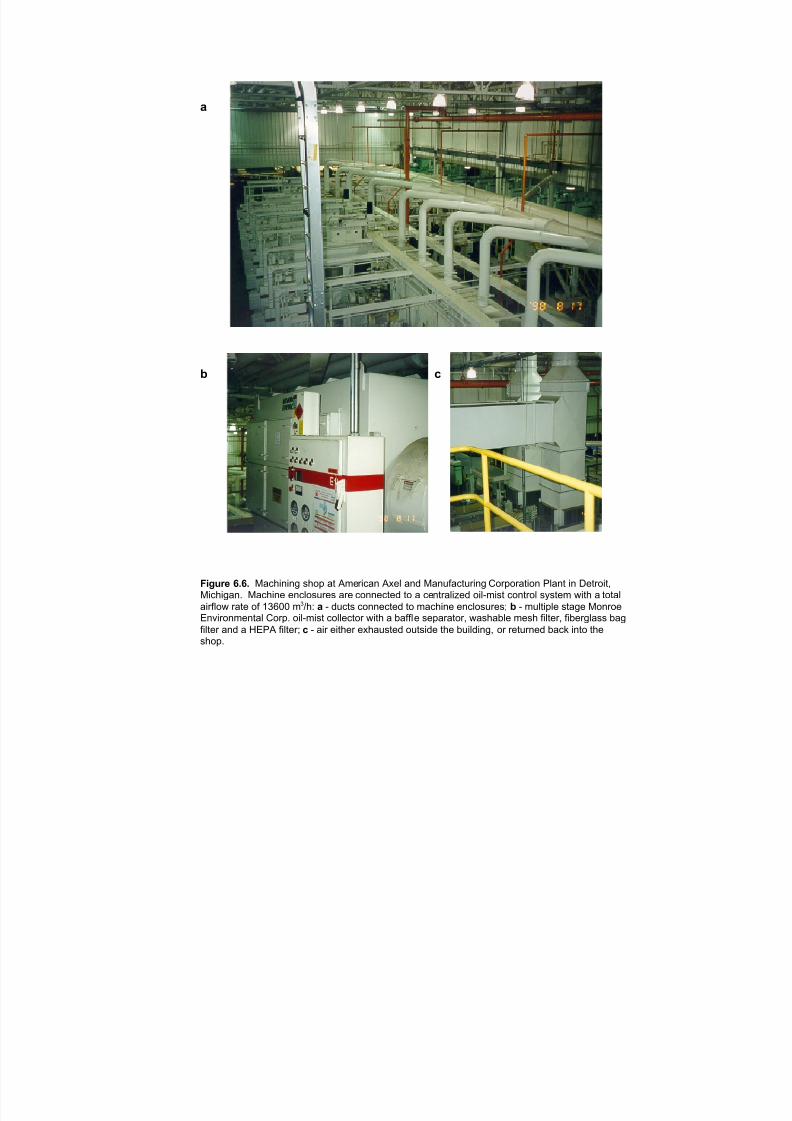
7/18/2019 Ventilation Guide
http://slidepdf.com/reader/full/ventilation-guide 100/223
!
" $
%&'()* +,+, "#$%&'&'( )%*+ #, -./0&$#' -1/2 #'3 "#'45#$,40&'( 6*0+*0#,&*' 72#', &' 8/,0*&,9"&$%&(#': "#$%&'/ /'$2*)40/) #0/ $*''/$,/3 ,* # $/',0#2&;/3 *&2<.&), $*',0*2 )=),/. >&,% # ,*,#2
#&052*> 0#,/ *5 ?@ABB . C%D ! < 34$,) $*''/$,/3 ,* .#$%&'/ /'$2*)40/)E " < .42,&+2/ ),#(/ "*'0*/@
F'G&0*'./',#2 6*0+: *&2<.&), $*22/$,*0 >&,% # H#552/ )/+#0#,*09 >#)%#H2/ ./)% 5&2,/09 5&H/0(2#)) H#(
5&2,/0 #'3 # IF7- 5&2,/0E $ < #&0 /&,%/0 /1%#4),/3 *4,)&3/ ,%/ H4&23&'(9 *0 0/,40'/3 H#$J &',* ,%/)%*+:

7/18/2019 Ventilation Guide
http://slidepdf.com/reader/full/ventilation-guide 101/223
a
b
Figure 6.7. Close capture for cast iron headmilling operation: a - with tunnel guarding androllaway hood. Operator straddles cutter duringtool change. Fine dust does not wear flex
ductwork excessively; b - duct swivels at joint toswing hood away from cutters for tool change.Operator straddles cutter during tool change.
Fine dust does not wear round elbows made of abrasion resistant plate. The same operation
as in (a) with a different approach to guarding anddust collection.

7/18/2019 Ventilation Guide
http://slidepdf.com/reader/full/ventilation-guide 102/223
Figure 6.8. Exhaust from aluminum block milling station enclosure. The designof machine enclosures and exhaust connections can be accomplished more efficientlyduring the initial phase of machine design. Casting materials change and tooling follows.This particular machine was designed for aluminum and cast iron. Aluminum machiningsometimes requires coolants over the tool and the cast iron tooling may require a dryenvironment. This station was designed for a low velocity exhaust pick up for mist control
during wet machining.
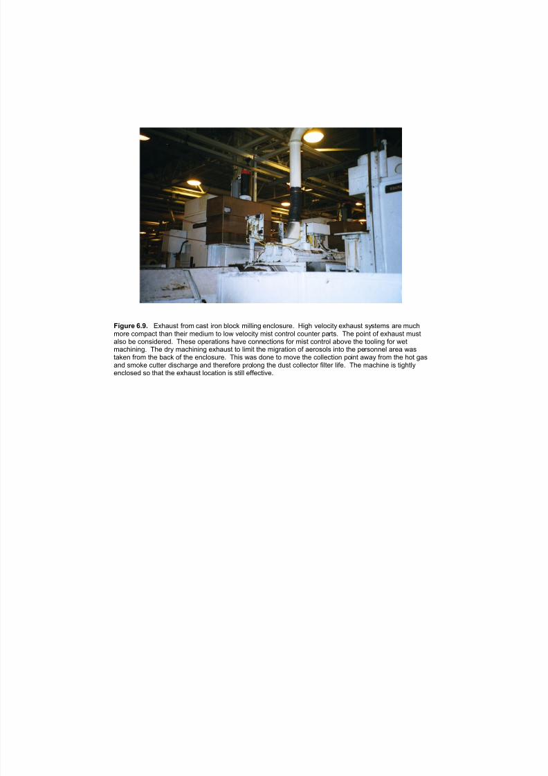
7/18/2019 Ventilation Guide
http://slidepdf.com/reader/full/ventilation-guide 103/223
)LJXUH çïäï ([KDXVW IURP FDVW LURQ EORFN PLOOLQJ HQFORVXUHï +LJK YHORFLW\ H[KDXVW V\VWHPV DUH PXFKPRUH FRPSDFW WKDQ WKHLU PHGLXP WR ORZ YHORFLW\ PLVW FRQWURO FRXQWHU SDUWVï 7KH SRLQW RI H[KDXVW PXVWDOVR EH FRQVLGHUHGï 7KHVH RSHUDWLRQV KDYH FRQQHFWLRQV IRU PLVW FRQWURO DERYH WKH WRROLQJ IRU ZHWPDFKLQLQJï 7KH GU\ PDFKLQLQJ H[KDXVW WR OLPLW WKH PLJUDWLRQ RI DHURVROV LQWR WKH SHUVRQQHO DUHD ZDVWDNHQ IURP WKH EDFN RI WKH HQFORVXUHï 7KLV ZDV GRQH WR PRYH WKH FROOHFWLRQ SRLQW DZD\ IURP WKH KRW JDVDQG VPRNH FXWWHU GLVFKDUJH DQG WKHUHIRUH SURORQJ WKH GXVW FROOHFWRU ILOWHU OLIHï 7KH PDFKLQH LV WLJKWO\HQFORVHG VR WKDW WKH H[KDXVW ORFDWLRQ LV VWLOO HIIHFWLYHï

7/18/2019 Ventilation Guide
http://slidepdf.com/reader/full/ventilation-guide 104/223
!"#$%& ()*+) !""#$%"& ()* +(,-.),/ 0,)% 1)%+ 2,2*/3 *24"52*3 #*"6 42,%*(.)72- "). 6)8%4",%*". 838%26 (% %+2 9:; <,/),2 =.(,% ), >%(32*? @08%*)(A
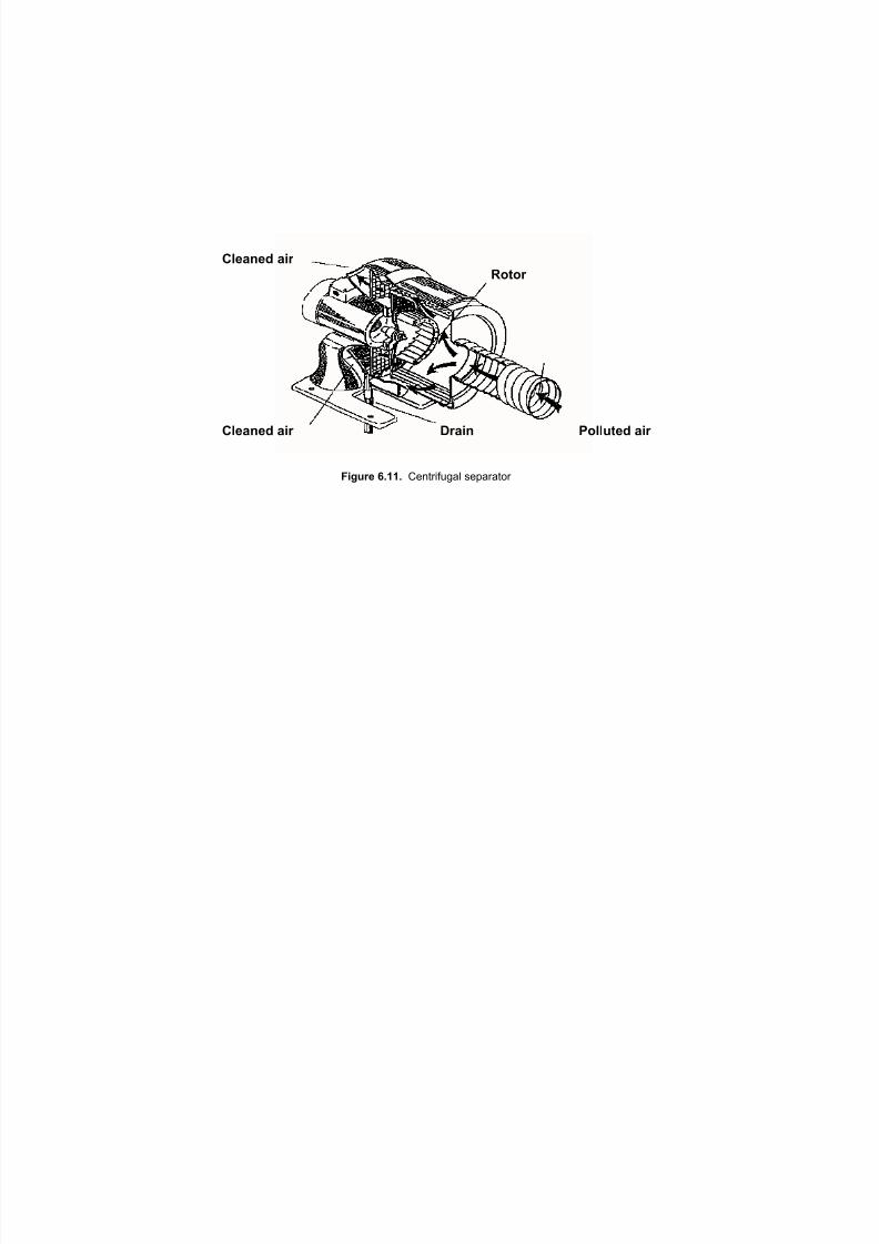
7/18/2019 Ventilation Guide
http://slidepdf.com/reader/full/ventilation-guide 105/223
Cleaned air
Rotor
Cleaned air Drain Polluted air
Figure 6.11. Centrifugal separator
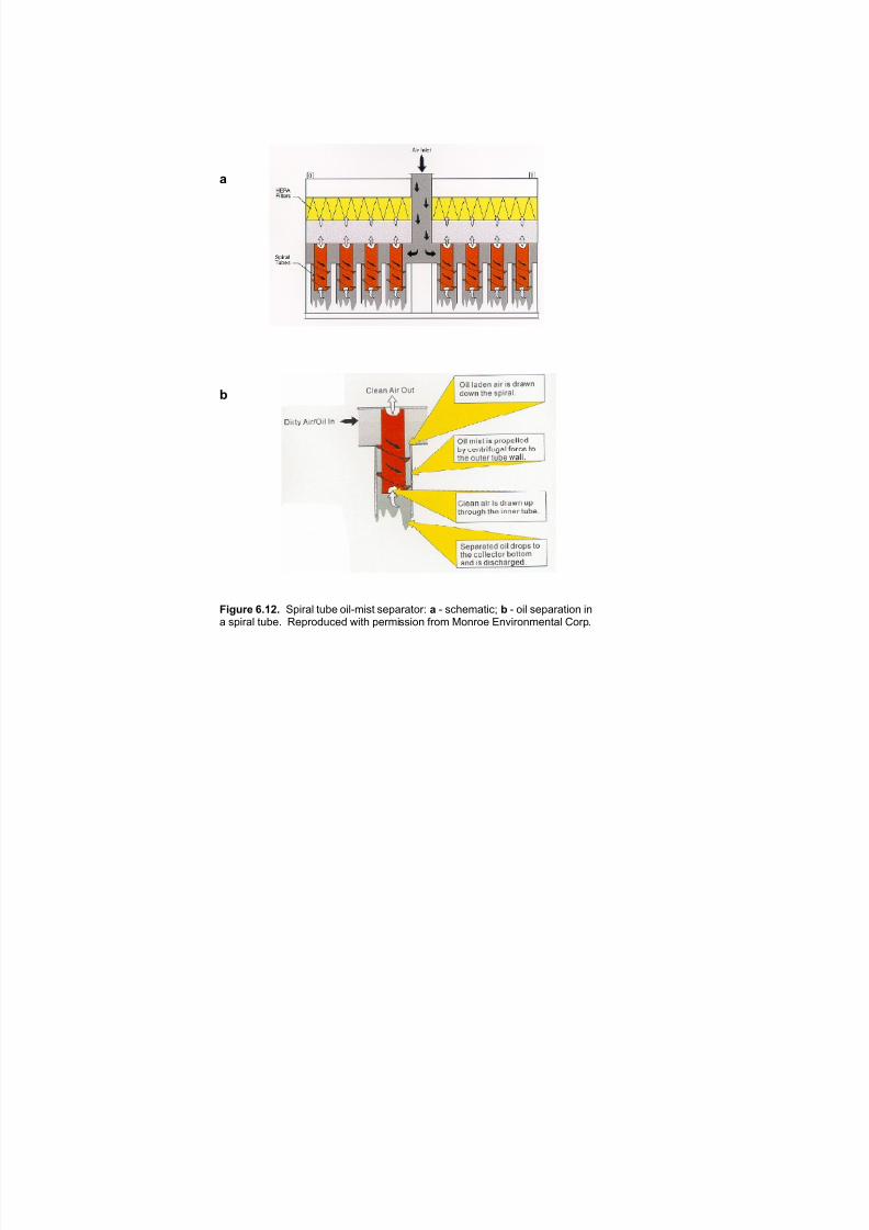
7/18/2019 Ventilation Guide
http://slidepdf.com/reader/full/ventilation-guide 106/223
a
b
Figure 6.12. Spiral tube oil-mist separator: a - schematic; b - oil separation ina spiral tube. Reproduced with permission from Monroe Environmental Corp.

7/18/2019 Ventilation Guide
http://slidepdf.com/reader/full/ventilation-guide 107/223
Clean air
Polluted air Polluted air
Figure 6.13. Buffle-type oil-mist separator (schematic)

7/18/2019 Ventilation Guide
http://slidepdf.com/reader/full/ventilation-guide 108/223
!"#$% $'(
)*""+,#- $'( )*""+,#- $'(
.'/+(# 01231 !"#$%&'(" *+ $,$"'-*.'&'(" +(,'$- +*- /01 %(.' .$2&-&'(*345$2-*67"$6 8('# 2$-%(..(*3 +-*% 9,:%*;$3' <=4

7/18/2019 Ventilation Guide
http://slidepdf.com/reader/full/ventilation-guide 109/223
"
# $
%&'()* +,-., "#$ %#&' ()$$*(')+ ,+)% -.()/ 0.12'* 3 4)5 6%/0 #1&'.$$*2 .' 789 :1;#1*<$.1' #1 ='.>*+? @A&'+#.5 4)$$*(')+ B#'C .1 .#+,$)B (.D.(#'> ), EF?FFF % GC C.& 'C+** ,#$'+.'#)1H
&'.;*& B#'C %*&C ,#$'*+&I " J ;*1*+.$ K#*B ), )#$ %#&' ()$$*(')+ #1 'C* &C)DL # J .$A%#1A% %*&C ,#$'*+ MNFF %% 2**DO? $ J P1#''*2 B#+* %*&C ,#$'*+ ), %*'.$$#(J&>1'C*'#( %.'*+#.$ MNFF %% 2**DO5
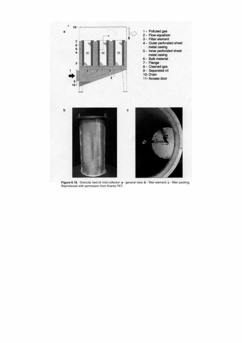
7/18/2019 Ventilation Guide
http://slidepdf.com/reader/full/ventilation-guide 110/223
10
8
7
6 5
4
3
1
2
9
10
Figure 6.16. Granular bed oil mist collector: a - general view; b - filter element; c - filter packing.
Reproduced with permission from Krantz-TKT.
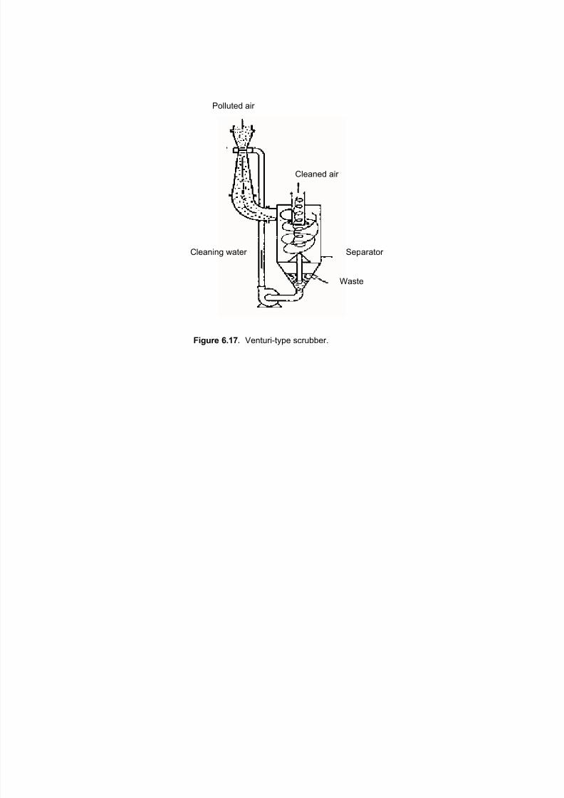
7/18/2019 Ventilation Guide
http://slidepdf.com/reader/full/ventilation-guide 111/223
"#$$%&'( )*+
,$')-'( )*+
,$')-*-. /)&'+ 0'1)+)&#+
2)3&'
!"#$%& ()*+) 4'-&%+*5&61' 37+%88'+9

7/18/2019 Ventilation Guide
http://slidepdf.com/reader/full/ventilation-guide 112/223
Figure 6.18. Schematic of an oil mist collector with an oil vapor condenser:
1 - cooling coil; 2 - condensate separator, 3 - fabric filter, 4 - fan, 5 - drain,
6 - electrical box, 7 - inspection door, 8 - compressor, 9 - condenser, 10 - controlvalve. Reproduced from [48].
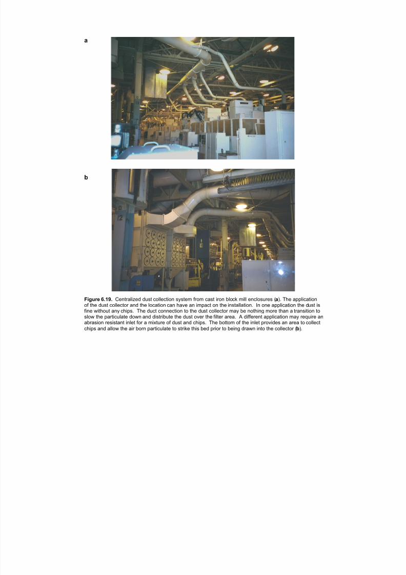
7/18/2019 Ventilation Guide
http://slidepdf.com/reader/full/ventilation-guide 113/223
a
b
Figure 6.19. Centralized dust collection system from cast iron block mill enclosures (a). The applicationof the dust collector and the location can have an impact on the installation. In one application the dust is
fine without any chips. The duct connection to the dust collector may be nothing more than a transition toslow the particulate down and distribute the dust over the filter area. A different application may require anabrasion resistant inlet for a mixture of dust and chips. The bottom of the inlet provides an area to collect
chips and allow the air born particulate to strike this bed prior to being drawn into the collector (b).
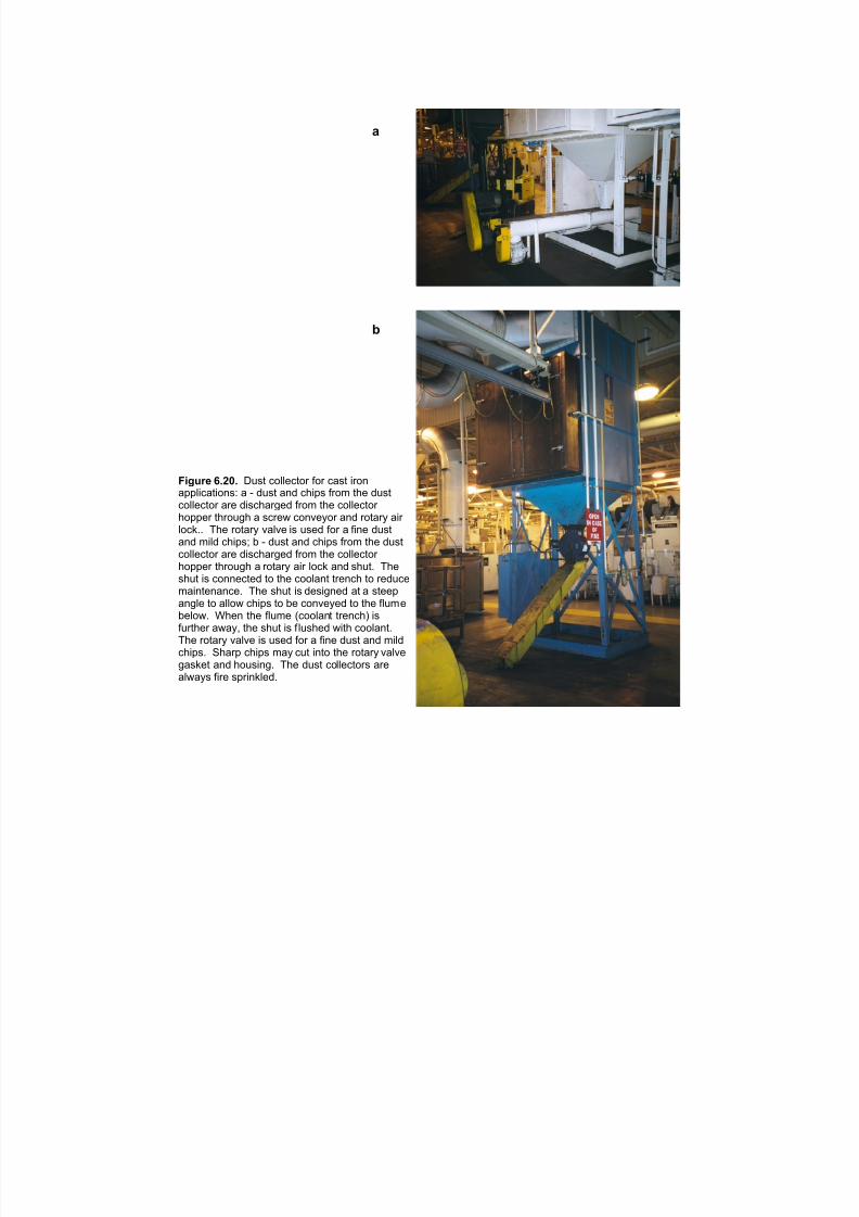
7/18/2019 Ventilation Guide
http://slidepdf.com/reader/full/ventilation-guide 114/223
a
b
Figure 6.20. Dust collector for cast iron
applications: a - dust and chips from the dustcollector are discharged from the collector hopper through a screw conveyor and rotary air lock.. The rotary valve is used for a fine dustand mild chips; b - dust and chips from the dustcollector are discharged from the collector hopper through a rotary air lock and shut. Theshut is connected to the coolant trench to reducemaintenance. The shut is designed at a steepangle to allow chips to be conveyed to the flumebelow. When the flume (coolant trench) isfurther away, the shut is flushed with coolant.The rotary valve is used for a fine dust and mildchips. Sharp chips may cut into the rotary valvegasket and housing. The dust collectors arealways fire sprinkled.
7/18/2019 Ventilation Guide
http://slidepdf.com/reader/full/ventilation-guide 115/223
7. ASSEMBLY PLANT
7.1. Process description. The operation of an automotive assembly line consists of long
straight line(s) or lines that weave back and forth through the assembly building. Pre-
manufactured parts or sub-assemblies such as drive train, engines, seats, body parts, and
other components are brought to the assembly line from adjacent storage areas via
conveyors or manual delivery. A speed-controlled conveyor moves the automotive chassis
from one station to another where parts are attached by assembly personnel or automatic.
At the end of the assembly line, the completed automobile is filled with operating fluids,
started for the first time and tested for proper engine/transmission operation and water seals
performance. It is then driven off the assembly line where it receives necessary alignment and
engine testing. If the vehicle passes inspection it will proceed outside to a storage lot for
later shipment to dealer. If the vehicle fails inspection due to improper operation it will
proceed to a mechanical or paint inspection and rework department for necessary repairs.
7.2. Process Emissions Overview. In most of the assembly plant the process generates
only heat primarily from the conveyer, electrical motors and lights. There are heat losses/gains
through the building envelope. Also, at the following workstations there are emissions of
contaminants:
• Windshield gluing station. Emissions are generated from the adhesive
compounds which are used to seal the windshield to the body frame. In many
cases this process is still performed manually, exposing the worker to hazardous
solvent vapor compounds which vary depending on manufacturer’s blend.
• Door seals and trim stations. Emissions are generated from adhesive
compounds that are used to attach door seals and interior trim components to
the body frame. The affixing of these components subject the worker to solvent
vapor compounds which are potentially hazardous but more likely to be annoying
or discomforting to the workers or operators in the surrounding areas.• Fuel filling station. Emissions are generated from gasoline and Diesel fuel
vapors which are generated during the first fueling process of the vehicle. These
vapors escape when the air is displaced by the liquid fuel as the fuel tank is filled.
Emissions also occur in this area due to spillage which occurs through worker
error.
• Vehicle engine start-up station. Emissions are generated from the first time
combustion process of the newly started engine. It produces high
concentrations of hydrocarbon as well as first time burn off of engine sealant.
Quite often emissions at this point are greater then under normal operation since
the engine has not been properly tuned. Since the engine has not been properly
tuned, the emissions, resulting from the incomplete combustion, generate PAHs
(polynuclear aromatic hydrocarbons) which have been identified as humancarcinogens.
• Chassis alignment inspection station. Emissions are generated from the
running of the vehicle when driving on to or off of the alignment pit. The
alignment inspector is subjected to exhaust gases which are heavier than air and
sink into the operator’s pit which increases the concentration of exhaust gases in
the workers breathing zone. These emissions are the same as experienced at time
of engine start-up.
7/18/2019 Ventilation Guide
http://slidepdf.com/reader/full/ventilation-guide 116/223
2
• Vehicle engine test station. Emissions are generated when the vehicle is placed
on a rolling road (Dyno test) and is accelerated to 50 mph. Since the vehicle’s
drive train is being engaged and the engine is now required to generate
horsepower, the vehicle engine components and exhaust system for the first time
are being subjected to elevated exhaust gas temperatures. These elevated
temperatures, along with the increased volume and velocity of exhaust gases,
bake off and displace contaminants such as engine sealant, lubricants and
coolants used to manufacture parts, and fiberglass packing fibers which are
manufactured into the exhaust muffler.
• Engine rework station. Emissions are generated when the vehicle is required to
run for the purposes of diagnosing an improperly running engine. In many cases
an engine technician must diagnose, adjust and/or repair a vehicle’s engine
resulting in sustained or elevated exhaust gas emissions being emitted into the
worked environment. He also is subjected to emissions being generated from
under the hood of the engine compartment where sealant or paint vapor
compounds or hydrocarbon emissions are being emitted into his breathing zone.
• Paint rework station. Emissions are generated when the vehicle requires paint
rework due to small-localized paint imperfections which were found during the
vehicle QC (Quality Control) inspection process. Workers in this area are
exposed to paint particulate and solvent vapors which are associated with the
painting process. Particulate control is also essential in this area for the purpose
of eliminating dust infiltration into the painting process.
• Certified fueling station. Emissions are generated by the fueling process of the
vehicle by EPA (Environmental Protection Agency) classified and certified fuel
used for the process of determining EPA mileage and emission standards for the
vehicle being manufactured. The emissions at this station are emitted during the
fueling process where the air in the tank is being displaced by the fueling liquids
and subsequently entering the workers breathing zone.
7.3. Sources of Auto Emissions. Pollutants are emitted from multiple sources from avehicle (auto, truck) while in the assembly. These emissions are even more concentrated when
the vehicle is first started. The following are the three greatest pollutant sources with the
highest level of toxic exposure to plant personnel (see Figure 7.1) [12].
1. The by-products of the engine combustion process (gas or Diesel) expose
workers to PNAs, NOx, CO , SO 2 , CO2 , and approximately 100 other VOC,
organic, acidic compounds.
2. Fueling losses expose workers to PNAs, benzene compounds, which have low
vapor point and are lighter than air.
3. Evaporation of fuels, solvents and oils which react together to develop into
complex chemical compounds.
Vehicle Exhaust Pollutants
Hydrocarbons (HC). Hydrocarbon emissions result when fuel molecules in the engine do not
burn or burn only partially. Hydrocarbons react in the presence of nitrogen oxides and
sunlight to form ground-level ozone , a major component of smog. Ozone irritates the eyes,
damages the lungs, and aggravates respiratory problems. A number of exhaust hydrocarbons
are also toxic with the potential to cause cancer.
7/18/2019 Ventilation Guide
http://slidepdf.com/reader/full/ventilation-guide 117/223
3
Nitrogen oxides (NOx). Under the high pressure and temperature conditions in an engine,
nitrogen and oxygen atoms in the air react to form various nitrogen oxides, collectively
known as NOx.
Carbon monoxide (CO). Carbon monoxide is a product of incomplete combustion and
occurs when carbon in the fuel is partially oxidized rather than fully oxidized to carbon dioxide
(CO 2 ). Carbon monoxide reduces the flow of oxygen in the bloodstream and is particularly
dangerous to persons with heart disease.
Carbon dioxide (CO2 ). In recent years, the U.S. Environmental Protection Agency (EPA)
has started to view carbon dioxide, a product of "perfect" combustion, as a pollution concern.
Carbon dioxide does not directly impair human health, but it is a "greenhouse gas" that traps
the earth's heat and contributes to the potential for global warming.
Diesel exhausts [9,18]. Workers exposed to Diesel exhaust face the risk of adverse health
effects:
Short-Term (Acute) Effects . Workers exposed to high concentrations of Diesel exhaust have
reported the following short-term health symptoms:
• irritation of the eyes, nose, and throat;
• lightheadedness;
• feeling "high"
• heartburn;
• headache;
• weakness, numbness, and tingling in extremities
• chest tightness;
• wheezing;
• vomiting.
Long-Term (Chronic) Effects. Although there have been relatively few studies on the long-
term health effects of Diesel exhaust, the available studies indicate that Diesel exhaust can be
harmful to your health. According to the National Institute for Occupational Safety and
Health (NIOSH), the International Agency for Research on Cancer (IARC) [11,15, 17], theEnvironmental Protection Agency (EPA), Diesel exhaust should be treated as a human
carcinogen (cancer-causing substance)[10].
Evaporative Emissions. Hydrocarbon pollutants also escape into the air through fuel
evaporation. Evaporative emissions occur several ways:
Diurnal: Gasoline evaporation from the fuel tank and venting gasoline vapors.
Running losses: The hot engine and exhaust system can vaporize gasoline when the
car is running.
Hot soak: The engine remains hot for a period of time after the car is turned off, and
gasoline evaporation continues when the car is parked.
Fueling: Gasoline vapors are always present in fuel tanks. These vapors are forced
out when the tank is filled with liquid fuel.
Idling Vehicle Emissions [8]. There are situations in which estimates of emissions from
idling vehicles are needed. As with driving emissions, idle emissions are affected by a number
of parameters. For analyses not requiring detailed specific emission estimates tailored to local
conditions, this summary of idle emission factors can be used to obtain first-order
approximations of emissions under idle conditions (e.g., drive-through lanes).
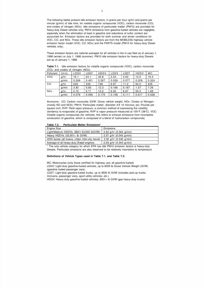
7/18/2019 Ventilation Guide
http://slidepdf.com/reader/full/ventilation-guide 118/223
4
The following tables present idle emission factors, in grams per hour (g/hr) and grams per
minute (g/min) of idle time, for volatile organic compounds (VOC), carbon monoxide (CO),
and oxides of nitrogen (NOx). Idle emissions of particulate matter (PM10) are provided for
heavy-duty Diesel vehicles only; PM10 emissions from gasoline-fueled vehicles are negligible,
especially when the elimination of lead in gasoline and reductions of sulfur content are
accounted for. Emission factors are provided for both summer and winter conditions for
VOC, CO, and NOx. These idle emission factors are from the MOBILE5b highway vehicle
emission factor model (VOC, CO, NOx) and the PART5 model (PM10 for heavy-duty Diesel
vehicles only).
These emission factors are national averages for all vehicles in the in-use fleet as of January 1,
1998 (winter) or July 1, 1998 (summer). PM10 idle emission factors for heavy-duty Diesels
are as of January 1, 1998.
Table 7.1. Idle emission factors for volatile organic compounds (VOC), carbon monoxide
(CO), and oxides of nitrogen (NOx).
Pollutant Units LDGV LDGT HDGV LDDV LDDT HDDV M C
VOC g/hr 16.1 24.1 35.8 3.53 4.63 12.5 19.4g/min 0.269 0.401 0.597 0.059 0.077 0.208 0.324
CO g/hr 229 339 738 9.97 11.2 94.0 435
g/min 3.82 5.65 12.3 0.166 0.187 1.57 7.26
N0x g/hr 4.72 5.71 10.2 6.50 6.67 55.0 1.69
g/min 0.079 0.095 0.170 0.108 0.111 0.917 0.028
Acronyms: CO: Carbon monoxide; GVW: Gross vehicle weight; NOx: Oxides of Nitrogen
(mostly NO and NO2); PM10: Particulate matter, diameter 3/4 10 microns; psi: Pounds per
square inch; RVP: Reid vapor pressure, a common method of expressing the volatility
(tendency to evaporate) of gasoline; RVP is vapor pressure measured at 100 °F (38°C). VOC:
Volatile organic compounds (for vehicles, this refers to exhaust emissions from incomplete
combustion of gasoline, which is composed of a blend of hydrocarbon compounds)
Table 7.2. Particulate Matter Emissions*
Engine Size Emissions
Light/Medium HDDVs (8501-33,000 lbGVW) 2.62 g/hr (0.044 g/min)
Heavy HDDVs (33,001+ lb GVW) 2.57 g/hr (0.043 g/min)
HDD buses (all buses, urban inter-city travel) 2.52 g/hr (0.042 g/min)
Average of all heavy-duty Diesel engines 2.59 g/hr (0.043 g/min)
* The only vehicle category for which EPA has idle PM10 emission factors is heavy-duty
Diesels. Particulate emissions are also observed to be relatively insensitive to temperature
Definitions of Vehicle Types used in Table 7.1. and Table 7.2:
MC: Motorcycles (only those certified for highway use; all gasoline-fueled)
LDGV: Light-duty gasoline-fueled vehicles, up to 6000 lb Gross Vehicle Weight (GVW)
(gasoline fueled passenger cars);
LDGT: Light-duty gasoline-fueled trucks, up to 8500 lb GVW (includes pick-up trucks,
minivans, passenger vans, sport-utility vehicles, etc.)
HDGV: Heavy-duty gasoline-fueled vehicles, 8501+ lb GVW (gas heavy-duty trucks)

7/18/2019 Ventilation Guide
http://slidepdf.com/reader/full/ventilation-guide 119/223
5
LDDV: Light-duty Diesel vehicles, up to 6000 lb GVW (passenger cars with Diesel engines)
LDDT: Light-duty Diesel trucks, up to 8500 lb GVW (light trucks with Diesel engines)
HDDV: Heavy-duty Diesel vehicles, 8501+ lb GVW (Diesel heavy-duty trucks)
7.4. Target levels. There is no OSHA standard for Diesel exhaust. However, OSHA does
have workplace exposure limits for individual components of Diesel exhaust, such as carbon
monoxide, sulfur dioxide, benzene, carbon dioxide, nitrogen dioxide, acrolein, and
formaldehyde.
In addition, OSHA has a standard for "nuisance" dust that is applicable to the soot in Diesel
exhaust. The standard limits "respirable" dust exposures (particles that are small enough to
lodge in the lung) to 5 milligrams per cubic meter of air (5 mg/m3) averaged over eight hours.
Because Diesel exhaust has been shown to cause cancer, NIOSH recommends that Diesel
exhaust exposures be reduced to the lowest feasible limits.
Table 7.3. Occupational exposure values [1,3,14]
Benzene, mg/m
3
CO, mg/m
3
CO2 ,mg/m
3
NOx , mg/m
3
PM, mg/m
3
OSHA,
PEL
3 55 9000 - 5
US
A
ACGIH,
TLV
1.6 29 9000 5.6 3
NIOSH,
REL
0.32 40 9000 - -
Sweden, LLV 1.5 40 9000 2 0.5
Germany, MAK - 35 9000 9.5 1.5
Russia, PDK 100 20 - 2 4
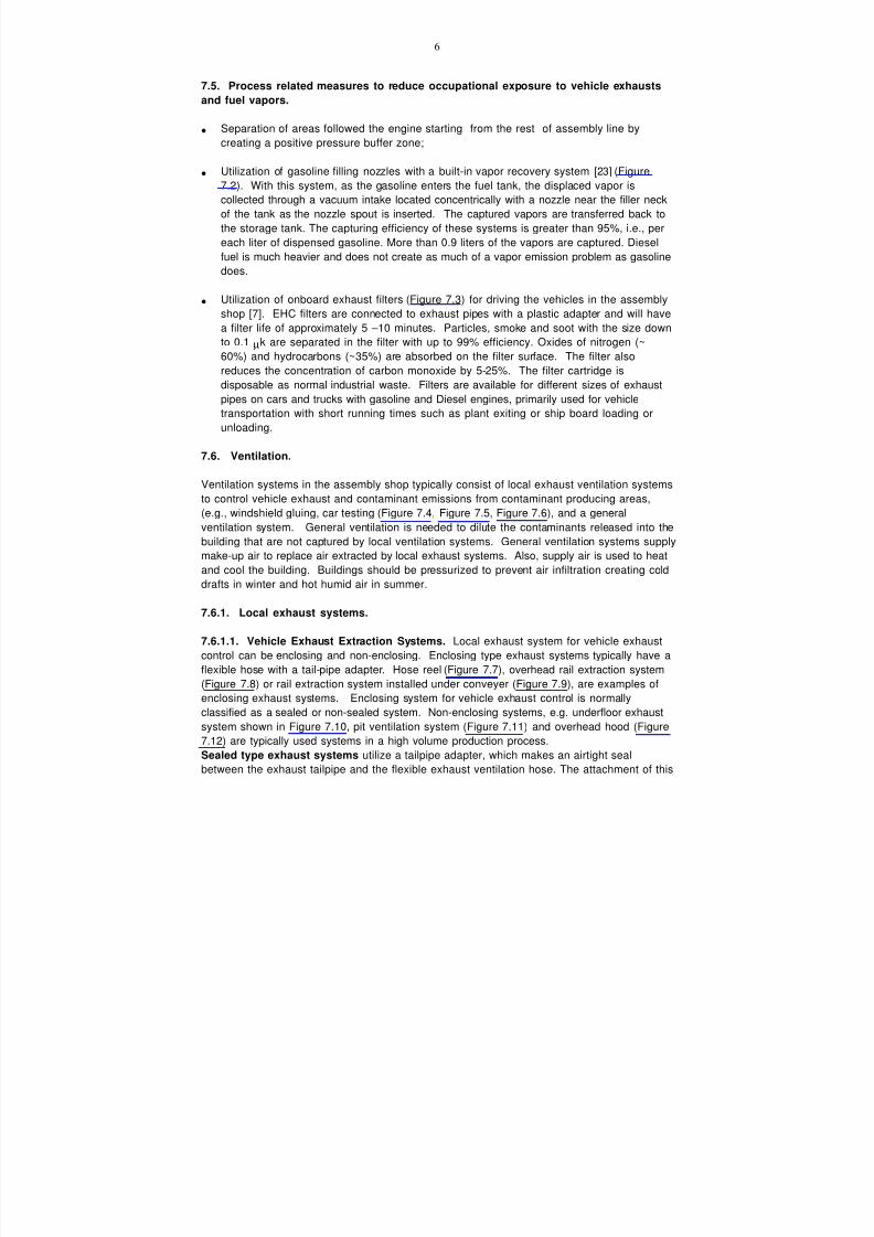
7/18/2019 Ventilation Guide
http://slidepdf.com/reader/full/ventilation-guide 120/223
6
7.5. Process related measures to reduce occupational exposure to vehicle exhausts
and fuel vapors.
• Separation of areas followed the engine starting from the rest of assembly line by
creating a positive pressure buffer zone;
• Utilization of gasoline filling nozzles with a built-in vapor recovery system [23] (Figure
7.2). With this system, as the gasoline enters the fuel tank, the displaced vapor is
collected through a vacuum intake located concentrically with a nozzle near the filler neck
of the tank as the nozzle spout is inserted. The captured vapors are transferred back to
the storage tank. The capturing efficiency of these systems is greater than 95%, i.e., per
each liter of dispensed gasoline. More than 0.9 liters of the vapors are captured. Diesel
fuel is much heavier and does not create as much of a vapor emission problem as gasoline
does.
• Utilization of onboard exhaust filters (Figure 7.3) for driving the vehicles in the assembly
shop [7]. EHC filters are connected to exhaust pipes with a plastic adapter and will have
a filter life of approximately 5 –10 minutes. Particles, smoke and soot with the size down
to 0.1 µk are separated in the filter with up to 99% efficiency. Oxides of nitrogen (~
60%) and hydrocarbons (~35%) are absorbed on the filter surface. The filter also
reduces the concentration of carbon monoxide by 5-25%. The filter cartridge is
disposable as normal industrial waste. Filters are available for different sizes of exhaust
pipes on cars and trucks with gasoline and Diesel engines, primarily used for vehicle
transportation with short running times such as plant exiting or ship board loading or
unloading.
7.6. Ventilation.
Ventilation systems in the assembly shop typically consist of local exhaust ventilation systems
to control vehicle exhaust and contaminant emissions from contaminant producing areas,(e.g., windshield gluing, car testing (Figure 7.4, Figure 7.5, Figure 7.6), and a general
ventilation system. General ventilation is needed to dilute the contaminants released into the
building that are not captured by local ventilation systems. General ventilation systems supply
make-up air to replace air extracted by local exhaust systems. Also, supply air is used to heat
and cool the building. Buildings should be pressurized to prevent air infiltration creating cold
drafts in winter and hot humid air in summer.
7.6.1. Local exhaust systems.
7.6.1.1. Vehicle Exhaust Extraction Systems. Local exhaust system for vehicle exhaust
control can be enclosing and non-enclosing. Enclosing type exhaust systems typically have a
flexible hose with a tail-pipe adapter. Hose reel (Figure 7.7), overhead rail extraction system(Figure 7.8) or rail extraction system installed under conveyer (Figure 7.9), are examples of
enclosing exhaust systems. Enclosing system for vehicle exhaust control is normally
classified as a sealed or non-sealed system. Non-enclosing systems, e.g. underfloor exhaust
system shown in Figure 7.10, pit ventilation system (Figure 7.11) and overhead hood (Figure
7.12) are typically used systems in a high volume production process.
Sealed type exhaust systems utilize a tailpipe adapter, which makes an airtight seal
between the exhaust tailpipe and the flexible exhaust ventilation hose. The attachment of this

7/18/2019 Ventilation Guide
http://slidepdf.com/reader/full/ventilation-guide 121/223
7
nozzle is usually through the use of an air filled bladder made of synthetic rubber which
conforms to the size of the vehicle’s tailpipe. This eliminates the escape of exhaust gases
when the vehicle is being accelerated or run on high idle testing. In turn, this reduces the
operating air volume.
(See Figure 7.7 and Figure 7.8 for examples of sealed exhaust systems.)
Non-sealed systems utilize a tailpipe adapter, which has a loose fit, which require a larger
volume of air to maintain a negative pressure control over the exhaust gases being emitted by
the vehicle. The attachment of this nozzle is usually by means of a mechanical device such as
vice-grip clamp or spring clip. (See Figure 7.6)
Approximate airflow rates to be extracted per vehicle from the exhaust pipe utilizing a sealed
fit tailpipe adapter or open-fit non-sealing tailpipe adapter are listed in Table 7.4. [19]
Down draft in-floor systems utilize an in ground floor ventilation duct which draws exhaust
gases through a floor grate into a concrete lined combination floor drain and ventilation duct.
An exhaust fan maintains a negative pressure of approximately 150-cfm per sq. ft. of open pit
area which is evacuated by a central roof or penthouse mounted exhaust fan system. In-floor
or pit exhaust systems require the highest volume of air and require periodic maintenance to
remove foreign debris, fuel, and oil or coolant spillage. E.g., in-floor exhaust system shown in
Figure 7.5 or a pit ventilation system shown in Figure 7.6.
Exhaust system evacuating exhaust gases though the in-floor opening with a flap is common
for engine testing booths (Figure 7.13). Air exhausted from the engine-testing booth may
contain fiberglass lints as a result of new mufflers burning. Thus, the exhaust system should
be equipped with an air filter to prevent outdoor air pollution (Figure 7.14).
The capturing effectiveness of sealed exhaust systems is high and for design purposes can be
considered 90% or higher. With non-sealed exhaust systems capturing effectiveness is below
75% [16].
Table 7.4. Airflow rates to be extracted per vehicle from the exhaust pipe utilizing a sealed
fit tailpipe adapter or open-fit non-sealing tailpipe adapter.
Sealed Fit Tailpipe Adapter
Veh. Type Engine Power (h.p.) Airflow rate cfm (m3 /h) Hose size
MC/ATV <100 200 (340) 3”
LDGV <130 300 (510 3”
LDGT < 175 450 (765)) 4”
HDGV < 250 500 (850) 4”
LDDV < 325 500 (850) 4”
LDDT < 400 500 (850) 4”
HDDV < 500 750 (1275) 5”
ORV < 600 1000 (1700) 6 “
Open Fit Non-Sealing Tailpipe Adapter
MC/ATV < 100 300 (510) 3”
LDGV < 130 450 (765) 4”
LDGT < 175 600 (900) 5”
HDGV < 250 750 (1275) 5”
LDDV < 325 750 (1275) 5”
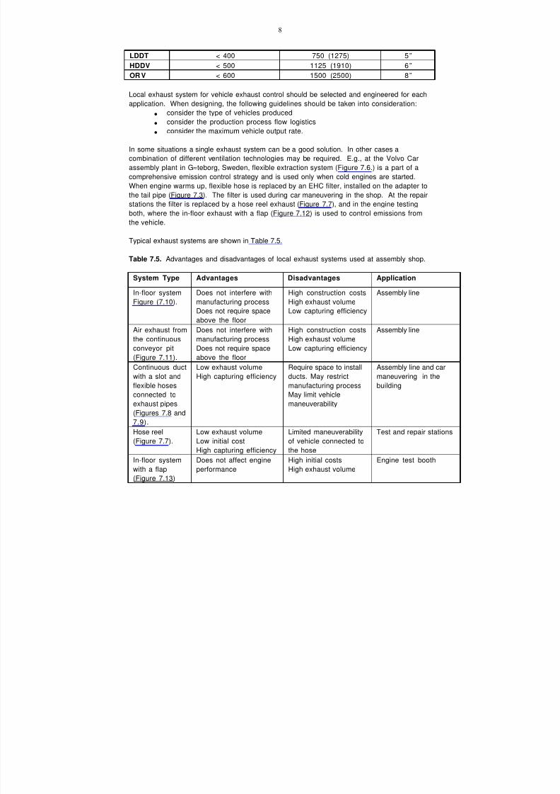
7/18/2019 Ventilation Guide
http://slidepdf.com/reader/full/ventilation-guide 122/223
8
LDDT < 400 750 (1275) 5”
HDDV < 500 1125 (1910) 6”
OR V < 600 1500 (2500) 8”
Local exhaust system for vehicle exhaust control should be selected and engineered for each
application. When designing, the following guidelines should be taken into consideration:• consider the type of vehicles produced
• consider the production process flow logistics
• consider the maximum vehicle output rate.
In some situations a single exhaust system can be a good solution. In other cases a
combination of different ventilation technologies may be required. E.g., at the Volvo Car
assembly plant in G≈teborg, Sweden, flexible extraction system (Figure 7.6.) is a part of a
comprehensive emission control strategy and is used only when cold engines are started.
When engine warms up, flexible hose is replaced by an EHC filter, installed on the adapter to
the tail pipe (Figure 7.3). The filter is used during car maneuvering in the shop. At the repair
stations the filter is replaced by a hose reel exhaust (Figure 7.7), and in the engine testing
both, where the in-floor exhaust with a flap (Figure 7.12) is used to control emissions fromthe vehicle.
Typical exhaust systems are shown in Table 7.5.
Table 7.5. Advantages and disadvantages of local exhaust systems used at assembly shop.
System Type Advantages Disadvantages Application
In-floor system
Figure (7.10).
Does not interfere with
manufacturing process
Does not require space
above the floor
High construction costs
High exhaust volume
Low capturing efficiency
Assembly line
Air exhaust from
the continuous
conveyor pit
(Figure 7.11).
Does not interfere with
manufacturing process
Does not require space
above the floor
High construction costs
High exhaust volume
Low capturing efficiency
Assembly line
Continuous duct
with a slot and
flexible hoses
connected to
exhaust pipes
(Figures 7.8 and
7.9).
Low exhaust volume
High capturing efficiency
Require space to install
ducts. May restrict
manufacturing process
May limit vehicle
maneuverability
Assembly line and car
maneuvering in the
building
Hose reel(Figure 7.7).
Low exhaust volumeLow initial cost
High capturing efficiency
Limited maneuverabilityof vehicle connected to
the hose
Test and repair stations
In-floor system
with a flap
(Figure 7.13)
Does not affect engine
performance
High initial costs
High exhaust volume
Engine test booth
7/18/2019 Ventilation Guide
http://slidepdf.com/reader/full/ventilation-guide 123/223
9
7.6.1.2. Windshield Gluing Station Ventilation. The vapors produced by this manual
process are captured by back draft or downdraft hood. Examples of the hoods used
are presented in Figure 7.4a,b. For design criteria refer to ACGIH [2], ASHRAE [4],
and DGB [6].
7.6.1.3. Door Seals and Trim Stations Ventilation. Local exhaust system use to
capture the vapors produced by this manual process is similar to those used at the
windshield gluing station: back draft or downdraft hood (see Figure 7.4.c). For
design criteria refer to ACGIH [2], ASHRAE [4], and DGB [6].
7.6.1.4. Chassis Alignment Inspection Station Ventilation – The ventilation
technique to properly ventilate the exhaust gases and evaporation of fluids off the
vehicle is typically handled with a combination system. The pit where plant personnel
are located is customarily ventilated through an in-floor method. Vehicle exhaust
gases should be removed through the means of a source capture hose extraction
system.
7.6.1.5. Engine Rework Station Ventilation – The ventilation technique to properly
ventilate the exhaust gases produced while testing and operating the car in these
service bays is typically through the use of retractable hose reels or retracting hose
drops that are located overhead adjacent to each work position. Fume extraction for
under hood vapors which the mechanic would be exposed to while working over the
engine compartment is most commonly handled through the use of a source capture
fume extraction arm with build in work lighting which ventilates vapors of evaporation
out of the workers breathing zone. Also, sidedraft and overhead hoods are used to
evacuate evaporative emissions from engine (Figure 7.5).
7.6.1.6. Paint Rework Station Ventilation – The ventilation technique to properly
ventilate this area is through the use of a combination system consisting of horizontal
flow push pull hoods along with a fume extractor arm with built in work lighting.
7.6.1.7. Certified Fueling Station Ventilation – The ventilation technique to properly
ventilate this area is through the use of either fuel vapor recovery system for higher
volume usage or a fume extraction arm and fan combination with an operating flow of
approximately 700-cfm. Note: Fume extractor and fan must be provided as explosion
resistant configuration.
7.6.2. General Supply Ventilation (see Chapters 9, 10, 11)
7.6.3. General Exhaust Systems. General exhaust systems complement local exhaust
systems by removing contaminated air not captured by local exhausts. Such systems usually
consist of inlets, ducts, and a fan. In some cases general exhaust can be provided by rooffans.
7.6.4. Exhausted Air Filtration and Recirculation
Source capture exhaust systems used for vehicle exhaust control, trimming and windshield
gluing areas typically do not include air cleaning equipment, although air filtration technology
does exist to allow for air cleaning before exhaust to atmosphere. It is not recommended
7/18/2019 Ventilation Guide
http://slidepdf.com/reader/full/ventilation-guide 124/223
10
that exhaust air off of these processes be recirculated even if air filtration devices are
incorporated in the system design. Air recirculation may be considered from the “clean” areas
(without contaminant emission).
Note: It has been discovered that new mufflers subjected to first time high temperatures
(Dyno testing) have experienced a condition where fibrous particulate along with tar-like
hydrocarbons contaminated the exhaust gases and were in high enough concentrations to
warrant air treatment before final exhaust to atmosphere. Thus, to prevent outdoor air
pollution, engine testing booth exhaust system (Figure 7.13) should be provided with an air
cleaner (Figure 7.14).
7.7. References
1. ACGIH. 1998. Guide to Occupational Exposure Values – 1998. American Conference
of Governmental Industrial Hygienists. Cincinnati, OH.
2. ACGIH. 1998. Industrial Ventilation. A Manual of Recommended Practice. 23rd
edition. American Conference of Governmental Industrial Hygienists. Cincinnati, OH.
3. AFS 1996:2. 1996. Occupational Exposure Limit Values. The Swedish National Board of
Occupational Safety and Health.
4. ASHRAE. 1999. ASHRAE Handbook. HVAC Applications. American Society of
Heating, Refrigerating and Air-Conditioning Engineers. Atlanta, GA.
5. BCH. 1990. Construction Requirements to Car Servicing Stations. BCH 01-89.
Russian Ministry of Automobile Transportation. Moscow.
6. DGB. 2000. Industrial Ventilation Design Guidebook. Fundamentals. Academic Press.
7. EHC. 1998. Techniques and filtering of petrol- and Diesel -exhaust gases. EHC
Teknic AB.
8. EPA. 1998. United States Environmental Protection Agency. Air and Radiation
Office of Mobile Sources. EPA 420-F-98-014. April 1998.
9. EPA. 1996. United States Environmental Protection Agency. EPA 420-F95-009b.
June 1996. OMS Fact Sheet.10. EPA. 1994. U.S. Environmental Protection Agency (March and September 1994).
Health Assessment Document for Diesel Emission (external review draft), Vols. I-III,
EPA/600/8-90/057.
11. EPA. 1994. California Environmental Protection Agency, Office of Environmental
Health Hazard Assessment (June 1994). Health Risk Assessment for Diesel Exhaust
(preliminary review draft).
12. EPA. 1994. United States Environmental Protection Agency. EPA 400-F-92-007.
August 1994. Fact Sheet OMS-5.
13. Ford. 1990. Heating, Ventilation and Air Conditioning. Ford Motor Company Plant
Engineering Office. July 1, 1990. M15-M25.
14. GOST. 1988. General Requirements to the Occupied Zone Air. GOST 12.1.005-88. Moscow.
15. IARC (1989). International Agency for Research on Cancer. Monographs on theEvaluation of Carcinogenic Risks to Humans, Diesel and Gasoline Engine Exhausts
and Some Nitrogens, Vol. 46.
16. Mercedes-Benz U.S. International, Inc. 1999. Private communications with Mr.
Richard Burnis. Tuscaloosa, AL.
17. NIOSH. 1990. NIOSH Risk Assessment "An Explanatory Assessment of the Risk of
Lung Cancer Associated with Exposure to Diesel Exhaust Based on a Study of Rats."
(Publication No. NTIS PB-91-116-269.)

7/18/2019 Ventilation Guide
http://slidepdf.com/reader/full/ventilation-guide 125/223
11
18. OSHA. 1998. Diesel Exhaust. Safety and Health. Fact Sheet.
19. Plymovent. 1998. Clean Fresh Air. Consultants Handbook. Vehicle Exhaust Products. Sweden:
Plymovent AB.
20. Scania Partner AB. 1997. Private communications with Mr. Karl Pontenius.
21. VDI. 1997. Air Conditioning Systems for Factories. VDI 3802. VDI – Richtlinien.
Dhsseldorf: VDI.
22. Volvo. 1998. Celero Support AB. Private communications with Mr. Sten-Arne
H@kansson.
23. Wayne. 1994. The Wayne Vac Assist Type Vapor Recovery System. Wayne Division,
Dresser Industries Inc. Technical Information: D10470394.
24. Woody, A. 1997. Ventilation Systems Applied to Automotive Manufacturing.
Proceedings of the 5th International Symposium on Ventilation for Contaminant
Control "Ventilation'97". September 1997. Ottawa.
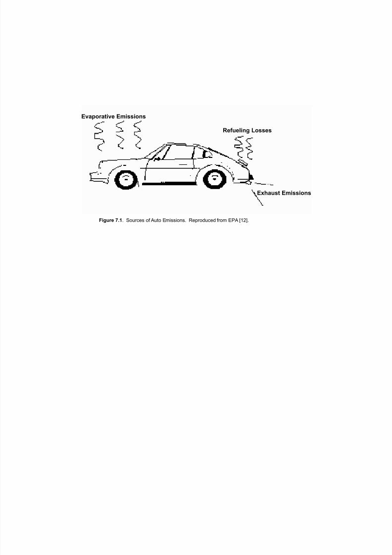
7/18/2019 Ventilation Guide
http://slidepdf.com/reader/full/ventilation-guide 126/223
Evaporative Emissions
Refueling Losses
Exhaust Emissions
Figure 7.1. Sources of Auto Emissions. Reproduced from EPA [12].
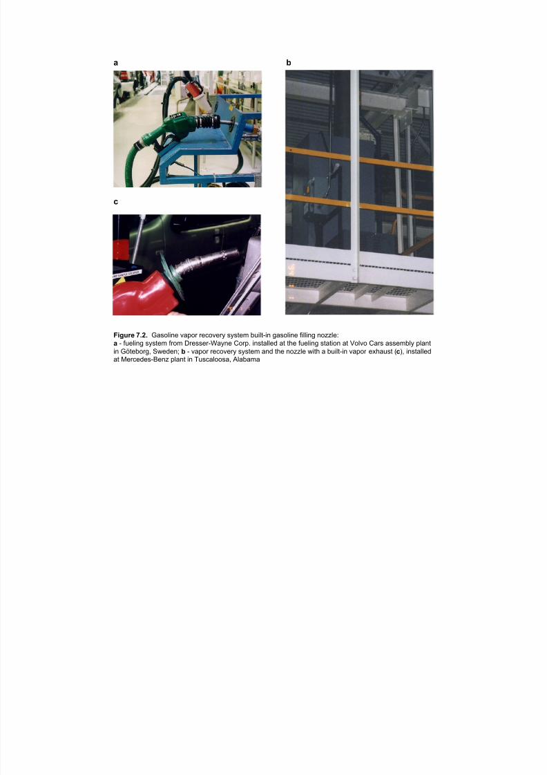
7/18/2019 Ventilation Guide
http://slidepdf.com/reader/full/ventilation-guide 127/223
a b
c
Figure 7.2. Gasoline vapor recovery system built-in gasoline filling nozzle:
a - fueling system from Dresser-Wayne Corp. installed at the fueling station at Volvo Cars assembly plant
in Göteborg, Sweden; b - vapor recovery system and the nozzle with a built-in vapor exhaust (c), installedat Mercedes-Benz plant in Tuscaloosa, Alabama

7/18/2019 Ventilation Guide
http://slidepdf.com/reader/full/ventilation-guide 128/223
a
b
Figure 7.3. EHC Exhaust Filter installed on the tail pipe of the car at Volvo Cars assembly plantin Göteborg, Sweden (a) and on the exhaust pipe of the truck (b).
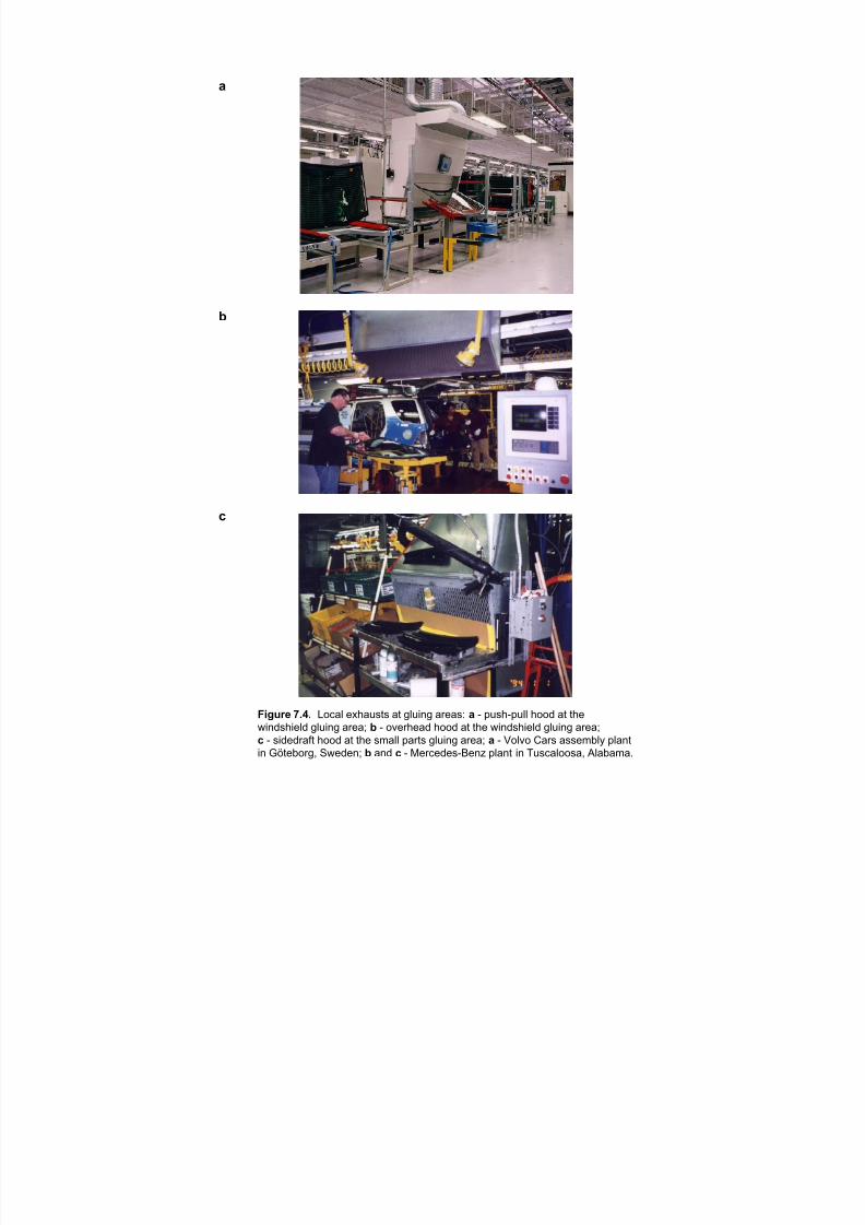
7/18/2019 Ventilation Guide
http://slidepdf.com/reader/full/ventilation-guide 129/223
D
E
F
)LJXUH æïéï /RFDO H[KDXVWV DW JOXLQJ DUHDVã D ð SXVKðSXOO KRRG DW WKH
ZLQGVKLHOG JOXLQJ DUHDâ E ð RYHUKHDG KRRG DW WKH ZLQGVKLHOG JOXLQJ DUHDâ
F ð VLGHGUDIW KRRG DW WKH VPDOO SDUWV JOXLQJ DUHDâ D ð 9ROYR &DUV DVVHPEO\ SODQW
LQ *|WHERUJñ 6ZHGHQâ E DQG F ð 0HUFHGHVð%HQ] SODQW LQ 7XVFDORRVDñ $ODEDPDï
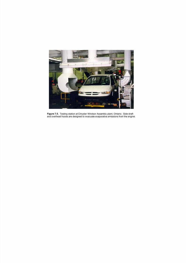
7/18/2019 Ventilation Guide
http://slidepdf.com/reader/full/ventilation-guide 130/223
!"#$%& ()*) !"#$%&' #$)$%*& )$ +,-.#/"- 0%&1#*- 2##"34/. 5/)&$6 7&$)-%*8 9%1":1-);$)&1 *<"-,")1 ,**1# )-" 1"#%'&"1 $* "<)=>)$" "<)5*-)$%<" "3%##%*&# ;-*3 $," "&'%&"8
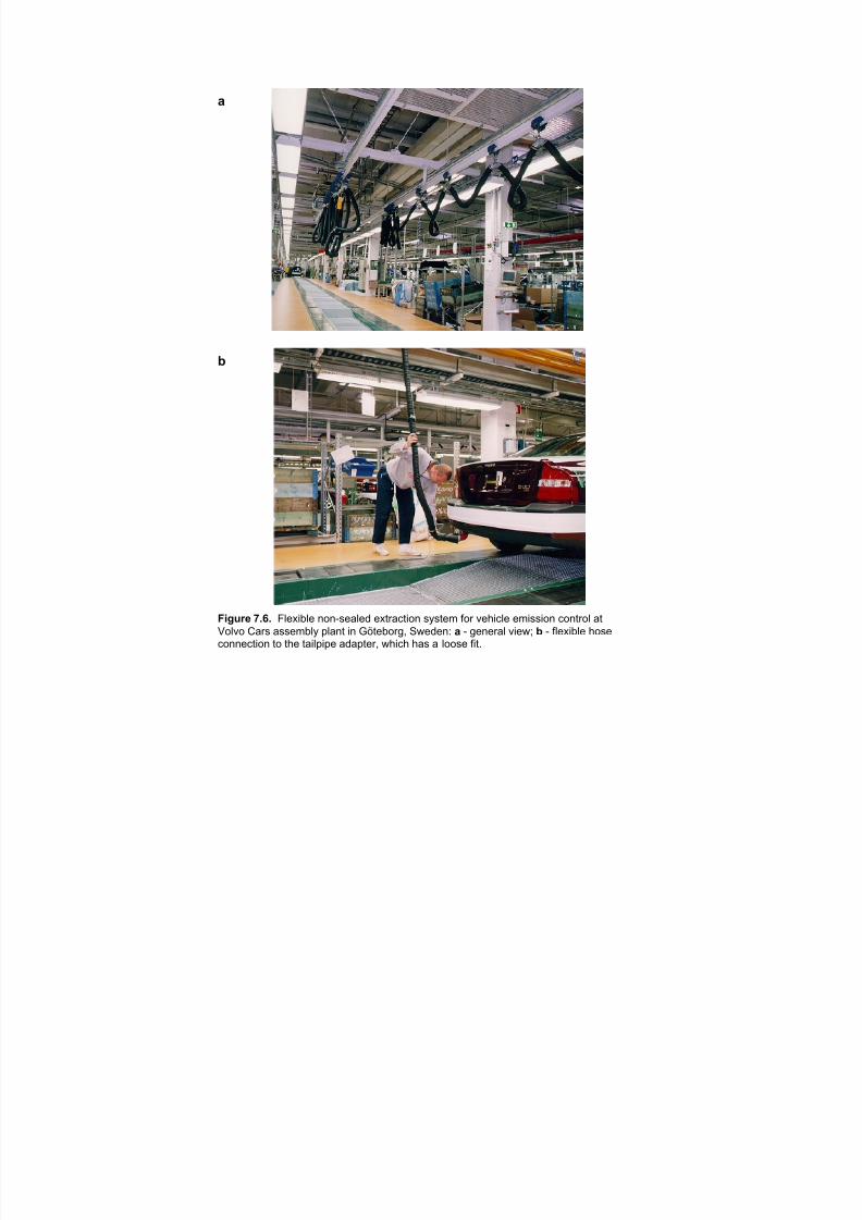
7/18/2019 Ventilation Guide
http://slidepdf.com/reader/full/ventilation-guide 131/223
a
b
Figure 7.6. Flexible non-sealed extraction system for vehicle emission control at
Volvo Cars assembly plant in Göteborg, Sweden: a - general view; b - flexible hoseconnection to the tailpipe adapter, which has a loose fit.
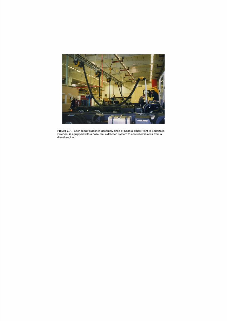
7/18/2019 Ventilation Guide
http://slidepdf.com/reader/full/ventilation-guide 132/223
Figure 7.7. Each repair station in assembly shop at Scania Truck Plant in Södertälje,Sweden, is equipped with a hose reel extraction system to control emissions from adiesel engine.
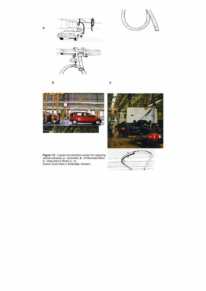
7/18/2019 Ventilation Guide
http://slidepdf.com/reader/full/ventilation-guide 133/223
a
b c
Figure 7.8. Looped rail extraction system for capturing
vehicle exhausts: a - schematic; b - at Mercedes-Benz A - class plant in Brasil; c - atScania Truck Plant in Södertälje, Sweden.
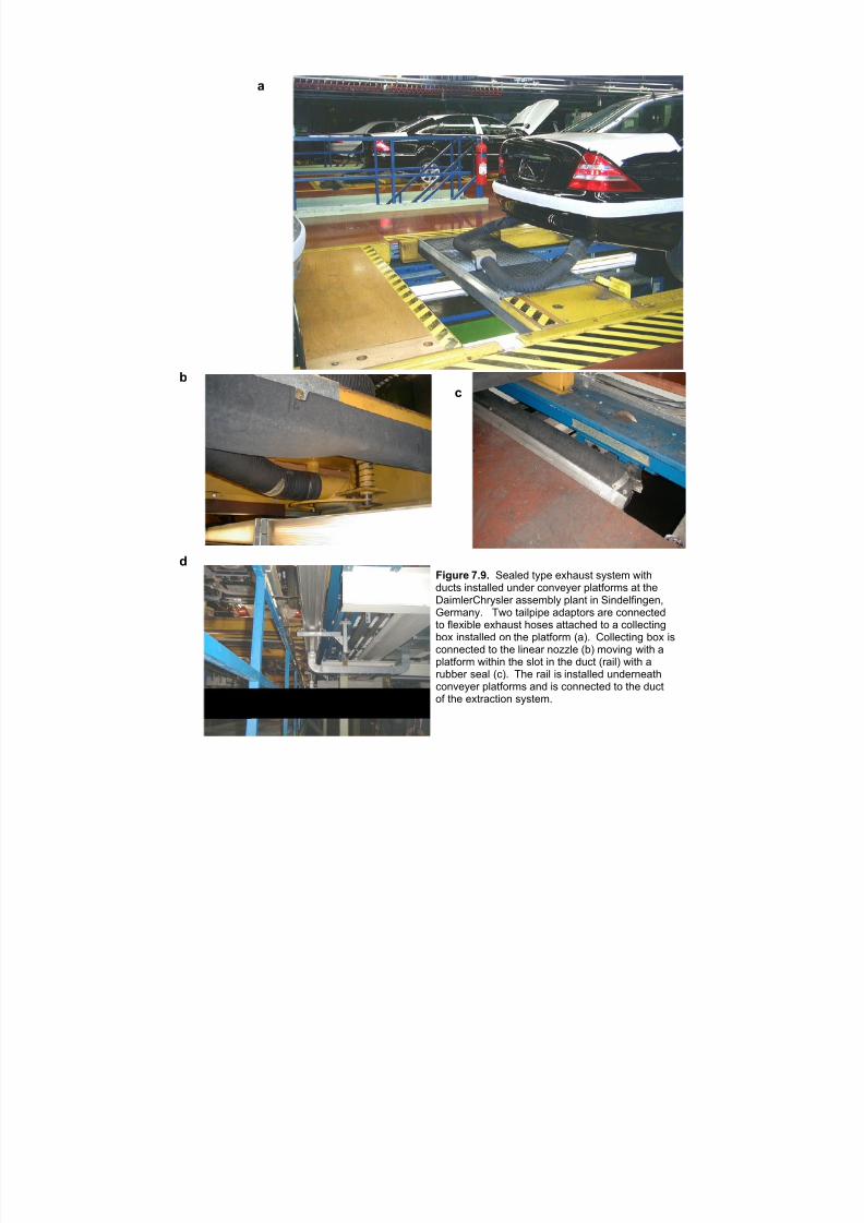
7/18/2019 Ventilation Guide
http://slidepdf.com/reader/full/ventilation-guide 134/223
D
E
F
G
)LJXUH æïäï 6HDOHG W\SH H[KDXVW V\VWHP ZLWKGXFWV LQVWDOOHG XQGHU FRQYH\HU SODWIRUPV DW WKH'DLPOHU&KU\VOHU DVVHPEO\ SODQW LQ 6LQGHOILQJHQñ*HUPDQ\ï 7ZR WDLOSLSH DGDSWRUV DUH FRQQHFWHGWR IOH[LEOH H[KDXVW KRVHV DWWDFKHG WR D FROOHFWLQJER[ LQVWDOOHG RQ WKH SODWIRUP õDôï &ROOHFWLQJ ER[ LVFRQQHFWHG WR WKH OLQHDU QR]]OH õEô PRYLQJ ZLWK D
SODWIRUP ZLWKLQ WKH VORW LQ WKH GXFW õUDLOô ZLWK DUXEEHU VHDO õFôï 7KH UDLO LV LQVWDOOHG XQGHUQHDWKFRQYH\HU SODWIRUPV DQG LV FRQQHFWHG WR WKH GXFWRI WKH H[WUDFWLRQ V\VWHPï
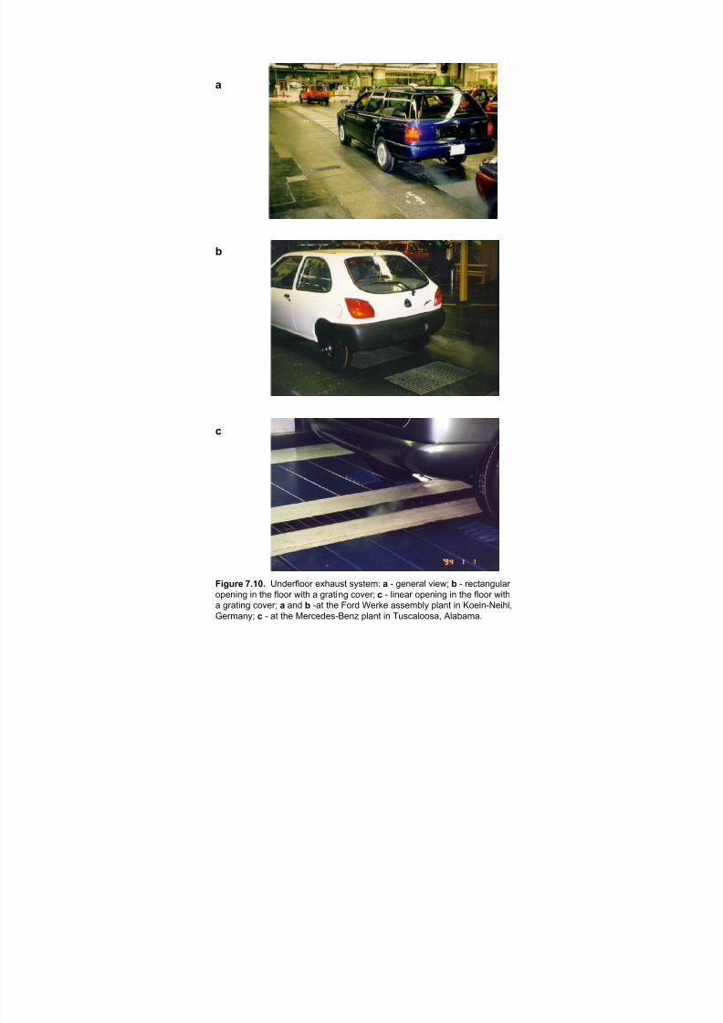
7/18/2019 Ventilation Guide
http://slidepdf.com/reader/full/ventilation-guide 135/223
a
b
c
Figure 7.10. Underfloor exhaust system: a - general view; b - rectangular
opening in the floor with a grating cover; c - linear opening in the floor with
a grating cover; a and b -at the Ford Werke assembly plant in Koeln-Neihl,
Germany; c - at the Mercedes-Benz plant in Tuscaloosa, Alabama.
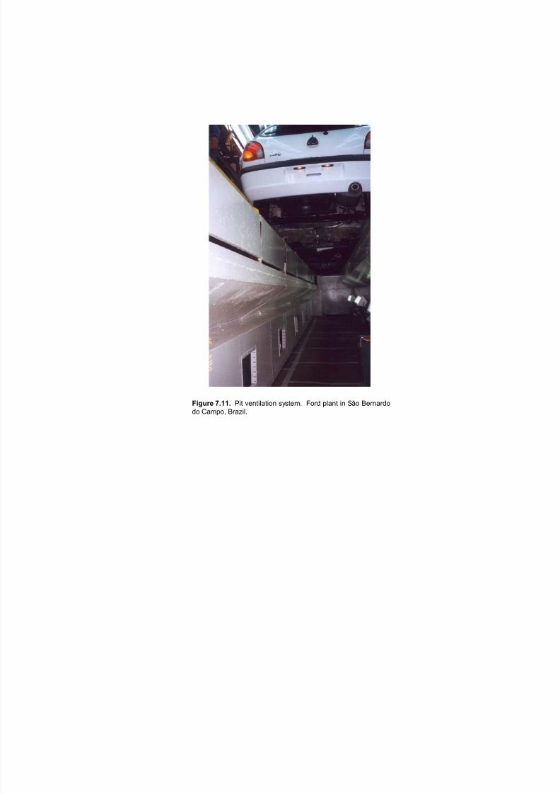
7/18/2019 Ventilation Guide
http://slidepdf.com/reader/full/ventilation-guide 136/223
Figure 7.11. Pit ventilation system. Ford plant in Sâo Bernardo
do Campo, Brazil.

7/18/2019 Ventilation Guide
http://slidepdf.com/reader/full/ventilation-guide 137/223
Figure 7.12. Canopy hood over the tractor vertical exhaust pipeat the assembly line of John Deere Davenport Works, Iowa.

7/18/2019 Ventilation Guide
http://slidepdf.com/reader/full/ventilation-guide 138/223
a
b
Figure 7.13. Underfloor exhaust system at the engine testing booth at VolvoCars assembly plant in Göteborg, Sweden: a - general view of the testing booth;b - exhaust opening with a flap.
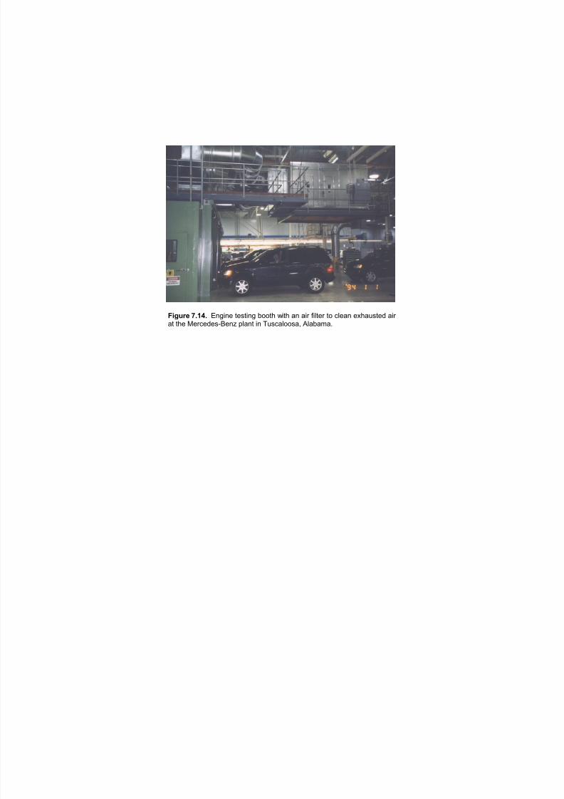
7/18/2019 Ventilation Guide
http://slidepdf.com/reader/full/ventilation-guide 139/223
Figure 7.14. Engine testing booth with an air filter to clean exhausted air
at the Mercedes-Benz plant in Tuscaloosa, Alabama.
7/18/2019 Ventilation Guide
http://slidepdf.com/reader/full/ventilation-guide 140/223
8. PAINT SHOPS AND AREAS
8.1. Process description. The purpose of paint on an automotive vehicle is to provide:
• Corrosion protection
• Mechanical protection, like scratch and stone chip
• Protection against atmospheric and natural influences, like chemical activity and mar;
• Optical appearance, color and general attractiveness
A typical automotive paint process is illustrated in Figure 8.1. It shows typical corrosion protection
measures, paint film layers and their necessary paint cure temperatures. It is important to understand
that the paint process may vary widely with both the paint vendor’s process and user’s requirements.
An automotive paint shop consists of a series of operation steps. Starting from the body shop, the
car bodies are transferred to the cleaning and phosphating pretreatment process, which is performed
either in spray or in a combination of spray and immersion process. After pretreatment phase, the
bodies are dip coated by means of the cathaphoretic paint deposition process (also called
Electrocoat, E-Coat, or ELPO), the purpose of which is to provide the basic corrosion resistance of
the bodies, The E-Coat paint is cured in the dedicated bake oven after which the bodies aretransferred to any necessary sanding operations, underbody protection coating and sealing
operations, followed by a sealer oven, in which the sealing materials are cured. The first spray paint
process is primer surfacer, which provides a mechanical anti chip protection of the E-coat paint and
makes the surface at the body more uniform for subsequent top coat application. The primer surfacer
paint is applied an outside and partly on inside surfaces depending of the color system as a single
color, 3-4, or more colors. The primer surfacer paint is cured; the bodies are transferred to sanding
operations and top coat preparation consisting of body cleaning outside (feather duster machines)
and partly inside (mostly manual). The bodies enter the base coat booth, where base coat paint is
applied, in most cases in two layers, inside (manual or robotic), outside (mostly automatic), followed
by a paint flashoff process and a final clear coat application. The topcoat paint application process is
finalized by curing, paint quality inspection stations, spat repair stations and transfer to the assembly
shop in the plant. Powder painting technologies are currently being utilized by several manufacturers.
8.1.1. Basic Technologies in Automotive Paint Finishing
The most important technologies applied in automotive paint shops are:
• Body conveyor systems, transportation, material handling, storage systems and logistics
• Body immersion systems for cleaning, degreasing, phosphating and corresponding process
equipment, including waste water and sludge treatment
• E-Coat body Immersion process technology, paint ultrafiltration, conditioning, circulation,
cathaphoretic deposition, anode system and grounding technology and DC rectifiers;
• Paint handling and atomization including paint mixing and preparation, paint circulation,
supply, dosing and metering, color change, flashing and rinsing, paint atomizers with sprayguns, high speed rotation bells and high voltage systems for electrostatic coating, as wall as
paint controls;
• Paint automation including reciprocator machines, robots and their central systems;
• Paint spray booths with air supply houses, air conditioning, distribution and controls;
• Spray booth exhaust systems including paint overspray collectors, droplet demister systems,
paint sludge treatment;
• Paint cure oven technology including oven tunnels, air circulation heater boxes and
7/18/2019 Ventilation Guide
http://slidepdf.com/reader/full/ventilation-guide 141/223
2
temperature central;
• Exhaust air pollution control including, abatement of VOC (volatile organic compounds) air
recirculation, solvent adsorption/ desorption systems and VOC incineration;
• Building, general plant facilities, ventilation and controls
The above list shows that a considerable part of the automotive paint shop technology is based on air
handling techniques. That is the reason why the process part of the paint shop business is
traditionally carried out by the paint system supplier, like ABB Fläkt, Air Industry Systems, Dürr,
Eisenmann, Haden, TKS, etc. At the same time this emphasizes the importance of air handling and
ventilation technology in the paint shop facilities industry.
8.2. Qualitative analysis of major loads and emissions from paint process.
All paint (with the exception of powder coatings) contains VOCs due to the solvent, which is the
major component of the paint formula. Tuluene and xylene are two of the many chemical compounds
used as paint solvents. Isocyanates are a by-product of the resin (binder) used in the paint formula.Some of these compounds are present during the paint application process. These compounds are
also given off during the curing process as auto bodies travel through the oven. The types and
quantities of specific compounds depend upon the process. Obtaining such information requires
coordination between the building engineers, process engineers and paint manufacturers. Properly
designed and operated paint booth should ensure contaminant emission into the building is below the
allowable limits.
This section covers a qualitative consideration of expected loads of air contaminated with organic
solvents or particulate emissions, as well as expected heat loads from the paint shop process to the
building. It will be divided into several sub sections, which handle individual parts of the paint process.
For more information refer to [7]
8.2.1. Pretreatment Line. Car body pretreatment line is generally built in the form of a tunnel with
relatively tight sheet metal housing, which covers a series of process spray or immersion tanks. It has
openings at the entrance side and at the exit of the tunnel, where some leakage of air loaded with
degreasing liquid spray fumes can be expected. It should not be higher than 4,000 - 5,000 m 3 /h per
an air seal zone and the liquid droplet concentration should not exceed 2000 mg/m 3 , if the process
and equipment is built and tuned properly. At the exit end of the pretreatment line a load of another
2,000-3,000 m3 /h humid air loaded with some relatively clean water droplets (from last spray rinse
stage after phosphate) can be expected. Depending of the conveyor used, there can be also other
openings, where some contaminated air loads can be expected. The phosphate line itself is internally
ventilated. Some leakage of air between the panels of the housing is possible in both directions (to
and/or from the inside), depending on the adjustment of ventilation pressures, but this leakage should
not be higher than 50-100 m3 /h per 1 m length of the tunnel, Of course, this may vary with the
quality of the manufacturing and installation of the tunnel and ventilation adjustments.
Major parts of the pretreatment line (degreasing, phosphating and rinsing stations) operate at
elevated temperatures. That is the reason why (in spite of insulation of tunnels and process tanks)
that some additional heat loads can be expected in the building. Their more exact evaluation is more
complex and is outside of the scope of this study.
7/18/2019 Ventilation Guide
http://slidepdf.com/reader/full/ventilation-guide 142/223
3
8.2.2. E-Coat Line. E-Coat line is in its technology rather similar to the pretreatment line. It uses
the same type of the conveyor and similar type of body immersion and spray treatment stages.
However, the process and the equipment are very different, including Paint circulation, UF system,
DC power supply, anode system and body grounding system. The E-Coat line is built as a series of 2
or 3 immersion tanks (E-Coat tank, UF permeate rinsing and DI water rinsing stages) and several
spray rinsing stations. The line is covered by the tunnel housing and ventilated. The E-Coat line
operates neatly at room temperature. The E-Coat paint circulation system is equipped with a cooling
system in order to keep the paint at a constant temperature (normally between 27 and 32oC).
8.2.3. Paint Spray Booth Lines. The main part of the spray booth is the booth itself through
which the bodies are transported mostly by a floor conveyor system and coated by automatically or
manually operated paint spray guns or high speed rotation electrostatic bell cup atomizers. The spray
booth height is normally 3.5 - 4.5 m and its width ranges between 4.5 and 6 m. The booth consists of
several paint application zones. Each zone is between 4 and 20 m long and the total spray booth
length for one type of coating (primer surfacer, base coat and clear coat) can be between 20 and 100m, depending on capacity. The booth is ventilated by conditioned air. The temperature of the air is
generally controlled to 20 -25oC (±1o C) and relative humidity of 50-70 % (±5% or even down to
±2-3% for water borne paint, the application of which is more sensitive to humidity), the air
downdraft velocities are between 0.2 and 0.5 m/s depending on type of the spray booth zone,
automation and application principles. The air supply system consists of air supply houses (air
conditioning units), mostly placed in a penthouse or upper floors of the paint shop building, air
distribution plenum and ductwork. The exhaust air from the spray booth is treated by a Venturi wet
scrubber or any other paint overspray collector in order to collect paint overspray particles. The
scrubber water is recirculated in the system and accumulated paint particles are collected in the form
of paint sludge. A reuse in automated booths of the spray booth exhaust air (several hundred
thousands m3 /h) is possible in the process and needs to be evaluated by OSHA or the governing
body. The paint sludge treatment system is based on processes of detackification, coagulation, aswell as flotation or sedimentation. The task of the system is to separate the paint sludge from
recirculation water in order to be able to use the water as long as possible and to dispose the
accumulated paint sludge. The paint sludge system is normally located in the lower floors of the paint
shop building. It has some environmental impact through potentially bad smell, leakage of recirculation
water and sludge. The ventilation requirements are not exactly defined and may vary from one plant
to the other.
Spray booths normally operate within a clean room that is maintained in a positive pressure mode in
order to prevent any dust or dirt of entering the paint booth area. The spray booths operate very
close to ambient temperatures, so that there should be no heat loss or gain in the building
surrounding the booth.
The penthouse areas of the paint shop building are normally warmer and noisier than the rest of the
building, due to the air heating system, air circulation fans and motors etc., but there are no standard
specifications for the calculation of building heat loads due to the equipment installed.
8.2.3. Paint Cure Ovens. Paint curing oven process requires heating up of the bodies normally
within 10 minutes to a temperature between 130 and 180oC and holding them at that temperature for
7/18/2019 Ventilation Guide
http://slidepdf.com/reader/full/ventilation-guide 143/223
4
20 minutes with a subsequent coating to approximately room temperature. There are many variations
of oven processes, temperature curves and designs. In addition there are different types of air seals,
in order to prevent heat losses and condensation of volatile compounds (straight through,
camelback, A-type).
Ovens normally operate in negative-pressure mode. Infiltration of 1,000 - 2.000 m3 /h per air seal
from the paint shop building. This air amount and the air needed to dilute the evaporated solvents and
water in the oven recirculation system are brought in by adding heated fresh air to the oven. The
fresh air can be preheated centrally for the oven tunnel, or locally for each oven zone. The sum
amount of the entrained and preheated fresh air is exhausted to the stack at a temperature of
approximately 120 - 160o C. This amount is normally between 5,000 and 20,000 m3 /h, depending of
the type of the oven, and its capacity and the sum of all oven exhausts from the paint shop can be
well over 100,000 m3/h. This waste energy can be used in principle, and it is used often in practice.
However, there are some difficulties due to the condensation tendency of residual solvents (after
incineration) and water vapor and corrosion risks due to a the presence of condensate at elevated
temperature. The reuse of energy needs to be evaluated on a case by case basis.
Other heat loads from the oven are heat transmission losses from the oven tunnel to the surrounding
and heat release from the body conveyor in entry and exit parts of the oven and eventually in the
conveyor return line.
Body cooling tunnel releases some energy load to the building as well. It has similar air seal losses or
gains as the oven itself. The exhaust air amount is large - roughly 50,000 - 100,000 m3/h or more per
cooling tunnel. The exhaust air temperature is only slightly elevated to 30 to 40oC. This air is difficult
to reuse for ventilation directly, due to contaminants. Its indirect use by heat recovery exchangers is
economically questionable, due to its relatively low temperature.
8.2.4. Other Automotive Paint Processes. There are other areas in the paint shop, which generally
belong to the spray booth technology, like sealing booths, panel and spat repair zones, sandingareas. They are continuous or stop-and-go work zones, where some specific operations are
performed. The ventilation rates vary with paint shop automation level and paint material in use.
8.3. Coordination of the HVAC and Process Engineers.
The first step in coordination with the process vendor is to understand where their HVAC
responsibility stops and where the building responsibility starts. The process vendor typically
provides all of the make-up air and exhaust air to and from paint booths and ovens. They may also
supply total HVAC of the clean room areas and spot cooling of workers on inspection, repair and
prep decks. Areas that the building HVAC encompass typically include phosphate, pre-coat HVAC;
oven area ventilation; inspection, sealer and repair deck general HVAC; and booth non clean room
area HVAC. General building exhaust from toilet rooms and battery charge areas are also typicallypart of the building team responsibilities. Once the definition of scope between process and building
is clear the transfer of information on all of the processes needs to start taking place. Because, in
most cases this is a simultaneous engineering task the first information received will generally be a
“best guess” with more firm information being provided as the design evolves. Information that is
crucial for the vendors to provide, to design the building HVAC system, includes:
7/18/2019 Ventilation Guide
http://slidepdf.com/reader/full/ventilation-guide 144/223
5
1. Heat rejection from equipment- this includes ovens, motors, booths, tanks, car
bodies, etc.
2. Make-up air or excess air volumes from booths and ovens.
3. Spot cooling supply and return or exhaust volumes and temperatures.
4. Any miscellaneous exhaust or supply air requirements.
8.4. Heat emission to the building
Process equipment is the major contributor to the paint shop heat gains. Information on heat
emission from the process is critical to calculate cooling loads for the different areas of the paint
shop. Also, cooling load calculations for each area need to include exterior roof and wall gains or
losses, interior wall losses or gains, interior lighting and people gains. A complete building heat
balance should be done to verify all loads are properly accounted for. For a typical paint shop with an
output of 40 jobs per hour internal loads may approach the following levels [5]:
Area Total heat load
Phosphate pre-coat area. 880,000W ( 3,000,000 Btu/h)Oven area. 1,470,000 W (5,000,000 Btu/h)
Oven strip-out area. 440,000 W (1,500,000 Btu/h)
Paint area. 1,173,000 W (4,000,000 Btu/h)
Note that these numbers are estimates only, and each paint shop has a different set of vendors and
processes.
8.5. Target level.
8.5.1. Air temperature, relative humidity, air cleanliness. Air temperature, relative humidity,
cleanliness within a paint shop are factors which are important for proper paint application and to
create comfortable working conditions. The clean room spaces and booths’ design requirements areprocess driven, as a function of paint vendor requirements. It is important to establish both indoor
and outdoor temperature and humidity design conditions for the non-clean room spaces. The non-
clean room spaces are comfort rather than process driven. The building outdoor design conditions
may be different for process and building. A temperature or humidity that exceeds the design
conditions may raise the temperature only several degrees in the building, but this rise could
compromise the paint finish, thus requiring more conservative outdoor design requirements for the
clean room and booth areas. Typical design temperatures and humidity for the building side of the
paint shop are:
Indoors:
Area Temperature, o C (o F) Relative Humidity
Phosphate pre-coat area. 80-90 N.C.
Paint area clean room. 80 60%Oven strip-out area 80-90 N.C.
Oven area 95-105 N.C.
Misc. work decks 80 N.C.
Paint Mix/Storage 72 50%
Penthouse Ambient + 10 N.C.
7/18/2019 Ventilation Guide
http://slidepdf.com/reader/full/ventilation-guide 145/223
6
Outdoors: ASHRAE 0.4% cooling design conditions.
Filtration should include 30% pre-filters on all systems with 90% final filters at booths and 65% final
filters on work decks.
8.5.2. Building pressure management. The pressure relationships between the different areas of
the building and adjacent body shops and assembly plants are critical to maintain the clean
environment required within the paint shop. All areas of the paint shop want to be at a positive
pressure with relationship to the outdoors and to the body shop and assembly plant. Also within the
paint shop itself there is a hierarchy of pressure relationships with the most critical areas being the
most positive. The relationships to the outdoors are as follows:
Area Pressure
Relationship
Body shop. Neutral
Phosphate pre-coat area. +
Oven area. ++Strip-out oven area. +++
Paint shop area. +++
Paint shop clean room area. ++++
Paint Booth +++
Assembly plant. Neutral
Setting up an air balance block diagram between the different areas of the building (Figure 8.2.) and
including all process and building supply and exhaust quantities, as well as transfer air between areas,
aids greatly in evaluating the overall building air balance. Pressure relationships between areas can be
maintained through several strategies. Providing constant volume systems that are properly balanced
is the most straightforward approach. Providing variable volume or staged fan systems that
modulate or cycle fans to maintain building differential pressures is a more sophisticated, but morecostly and cumbersome method. Differential pressure relationships and sensors are affected greatly
by prevailing winds and opening doors. When considering the building air balance and relative
pressure relationships it is important to be aware of the large volumes of air that transfer through the
many conveyor openings from one area to another.
8.6. Ventilation. Ventilation systems in paint shops typically consist of general supply and exhaust
systems. The major objectives of the paint shop building ventilation system are:
• Provide required make-up air for process
• Maintain proper building pressurization
• Maintain comfort for occupants in the building
• Provide adequate ventilation air for the occupants

7/18/2019 Ventilation Guide
http://slidepdf.com/reader/full/ventilation-guide 146/223
7
Typical ventilation rates for paint shop areas are:
Area m3 /m2h (cfm/ft2 ) ACH
Phosphate pre-coat area. 47 2.5 2.0
Oven area. 47 2.5 4.0
Strip-out area. 28 1.5 3.0
Paint shop area. 28 1.5 2.5
Note: these numbers are generalizations, and may vary greatly depending on the room supply air
temperature, discharge air temperature, heat load and total room volume.
The strategy of reusing air by transferring from more critical temperature and higher pressure spaces
to less critical temperature and lower pressure spaces reduces the total air required and increases the
ventilation rate through high temperature spaces like the oven areas. Transfer fans between areas,
helps to maintain pressurization and distribute transferred air. Building exhaust fans are located in
the oven area, strip-out area and phosphate area as required to maintain the building air balance.
Before any ventilation scheme is finalized a thorough review of local building codes should be
undertaken and possibly a meeting with the architect, owner and the local building code official. Key
issues include smoke purging, fire dampers and the transfer of large amounts of air from one area to
another.
8.6.1. Coordination between process and building ventilation. Make-up air and exhaust air to
and from paint booths and ovens are provided by process ventilation systems. HVAC systems
design of the “clean room” areas and spot cooling of workers on inspection, repair and preparation
decks is also responsibility of process engineers. Areas, for which HVAC systems are designed by
building ventilation engineers, are: phosphate, pre-coat HVAC; oven area ventilation; inspection,
sealer and repair deck general HVAC.
8.6.2. General supply systems. General ventilation supplies 100% outdoor air. The supply air flow
rate should exceed the make-up air flow for booths and ovens and be sufficient for building pressure
management. General ventilation supply units are located on the building roof or in a penthouse. For
more detail on General supply systems refer to [1,2,3,4,5] and see Chapters 9, 10, 11.
8.6.3. General exhaust systems typically include roof mounted exhaust fans located in the oven
area, laydown area and phosphate area as required to maintain the building air balance.
8.6.4. Air distribution. HVAC designers should try to supply air into the lower zone (at the floor
level where possible) with air diffusers installed evenly along the shop. However, in nearly all paint
shops some dumping of air is unavoidable, due to process restrictions. For more information on airdistribution practices in paint shops refer to [2,3,6] and see Chapter 10.
7/18/2019 Ventilation Guide
http://slidepdf.com/reader/full/ventilation-guide 147/223
8
8.7. References
1. ASA. 1964. American Standard Safety Code for the Design, Construction, and Ventilation
of Spray Finishing Operations. September 18, 1964. ASA, Inc.: New York.
2. INRS. 1991. Guide for ventilating practice. No.9. – Ventilation of paint booths and paint
areas. (Ventilation des cabines et postes de painture.) ED 663. INRS: Paris. (in French)
3. INRS. 1987. Guide for ventilating practice. No.10. – Paint of large and/or bulky equipment.
ED 713. INRS: Paris. (in French)
4. Montmoreau, Bertrand. 2000. HEPA Filtration in paint booth and oven booth. Paint shop
building heating ventilating and air conditioning. Proceedings of the 4th International
Conference “Ventilation for Automotive Industry”. Aachen, Germany. June 19-21. Zhivov&
Associates, L.L.C.
5. Richards, John. 2000. Paint shop building heating ventilating and air conditioning.
Proceedings of the 4th International Conference “Ventilation for Automotive Industry”.
Aachen, Germany. June 19-21. Zhivov& Associates, L.L.C.6. Sodec, Franc. Air distribution systems for paint shops. Paint shop building heating
ventilating and air conditioning. Proceedings of the 4 th International Conference “Ventilation
for Automotive Industry”. Aachen, Germany. June 19-21. Zhivov& Associates, L.L.C.
7. VDI. 1996. VDI 3455. Emission Reduction: Volume production – car body painting plants.
April 1996. VDI: Dhsseldorf.
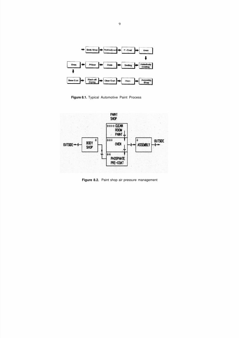
7/18/2019 Ventilation Guide
http://slidepdf.com/reader/full/ventilation-guide 148/223
9
Figure 8.1. Typical Automotive Paint Process
Figure 8.2. Paint shop air pressure management

7/18/2019 Ventilation Guide
http://slidepdf.com/reader/full/ventilation-guide 149/223
9. GENERAL VENTILATION SYSTEMS
9.1. Types of General Ventilation Systems. General ventilation systems (supply and exhaust) canbe mechanical or mixed (natural supply, mechanical exhaust). Natural air supply through the windows,doors or fixed air vents is not recommended when the width of the building exceeds 24 m (79 ft).Also uncontrolled air supply may disturb the process (e.g., gas shielding by creating high air velocitiesin the welding zone).
9.2. General Supply Systems. General supply systems are used for:• heating or cooling working environment;• removing contaminants not captured by local ventilation systems;• replacement of air exhausted by local ventilation systems and process equipment; and• controlling building pressure and airflow from space to space.
These systems typically consist of:• outside air inlet;• return air inlet;• supply air handling unit,• air distribution ductwork, and• supply air outlets.
9.3. General Exhaust Systems. General exhaust systems complement local exhaust systems byremoving air contaminated by fumes, gases or particles not captured by local exhausts.
Such systems usually consist of outlets, ducts, an air cleaner and a fan. The efficiency of the aircleaner must be sufficient to meet the regulations of environmental agencies and may be affected bylocation, background concentration in the atmosphere, nature of contaminants, height and velocity ofthe air discharge stack. In some cases the air cleaners may be excluded from the general exhaustsystem and general exhaust can be provided by the roof fans.
9.4. Centralized and decentralized (modular) systems. Centralized ventilation systems supply airto entire shop and have a large air distribution ductwork (Figure 9.1). Centralized system has lowermaintenance costs compared to decentralized system. With decentralized ventilation (Figure 9.2), theentire shop area is divided into zones, ventilated by a separate system with or without air distributionductwork. Decentralized units are normally located in the upper level below the roof (in the trussspace) or on the roof. Decentralized systems provide better temperature and air pollution control inshops with spaces having different cooling/heating and contaminant loads. Also, decentralizedsystems allow faster response to the change of the load by production process in different zones.Normally centralized system does not have a capability for zonal control. In comparison to centralunits, decentral units incur less costs when retrofitting existing shops.
9.5. Constant air volume (CAV) and variable air volume (VAV) systems (Figure 9.6). Theairflow rate supplied into the shop throughout the year may be constant (Constant Air Volumesystems) or variable (Variable Air Volume systems). The design of the air supply system is normallybased on the full load (cooling, contaminant or make-up airflow needs). When only a partial loadexists (e.g., in body and welding shops, assembly shops), thermal or pollution control may beachieved either by changing supply air temperature and/or the ratio of the outdoor and return air(CAV systems) or by changing the supply airflow rate (VAV systems).
The required supply airflow rate may vary significantly between winter and summer conditions orbetween different shifts (e.g., by 65% in body shops and machining shops with tempered airsystems, and by 80% with non-tempered air systems. [5]
Often, ventilation systems for automotive plants are designed when the machinery equipment datamay not be available. Ventilation system designs may be required to account for some future buildingexpansions and changes in processes or space requirements. In such situations ventilation systemcan be sized considering the maximum possible load with an airflow control based on the current load.
7/18/2019 Ventilation Guide
http://slidepdf.com/reader/full/ventilation-guide 150/223
2
VAV systems save heating, cooling and fan energy in comparison with CAV systems [2], but mayrequire more maintenance costs and expertise to operate them. In some cases they can incur lesscosts when retrofitting existing shops. VAV systems allowing significant reduction of supply airflowrate require special attention to:
• selection of airflow control strategy (inlet vanes, fan motor speed control, etc.)• ductwork design;• air space air distribution; and• building pressure management (coordination of supply and exhaust systems operation).
9.6. Air handling unit. The supply air handling unit components and configuration depend on thesystem usage (make-up air system, dilution ventilation system, heating and cooling, etc.), climaticconditions, and operating modes (CAV or VAV systems).
Typically, air-handling units have components to temper, clean, mix (outside air and return air), and tomove the air. In situations discussed in Chapter 11 air handling unit may have equipment to recoveryenergy from the air exhausted outside to lower the enthalpy (temperature) of the air supplied into thebuilding during the warm weather and to raise it during the cold weather. A microprocessor controlsthe air handling unit devices through sensors and actuators.
9.7. Working environment heating and cooling.
9.7.1. Heating systems. In machining, painting and body shops there is a significant surplus heatgenerated by internal heat sources. Thus, in most climatic conditions, cooling of the space is objectivefor most of the year. In large shops, heat typically needs to be applied to only the perimeter spaces.The internal area of the shop can maintain comfortable temperatures using the heat given off by theprocess. In machining, painting and body shops located in cold climates and assembly shops housingthe processes with lower heat production, occupied zone air temperature in heating season is typicallycontrolled with warm air heating combined with ventilation system. Supply air is heated in the airhandling unit with heated water flowing through the heating coil or in direct fired gas heatingsections. When piped natural gas is available the fired-gas approach is preferable, since it offersalmost 100% heating efficiency by burning the gas in the supply air stream (Figure 9.3a). Sufficientamount of outside air must be supplied to prevent the build-up of carbon dioxide in the building. An
alternative heating approach is indirect, gas-fired heating (Figure 9.3b), but it has a higher first costand the heating efficiency is less than with direct gas-fired.
Temperature control can be also achieved with separate air heating systems, e.g.,• recirculating or mixed air units located on walls and columns (Figure 9.4)• hot water or indirect gas-fired overhead radiant heating systems (Figure 9.5).
9.7.2. Cooling systems. In cooling season air temperature in the building is controlled either bybringing additional outside air or by using refrigeration equipment to cool the air. Cooling systems inautomotive plants are not designed to provide high level of comfort or control humidity, but only tocontrol the temperature at the level below 80
oF (27
oC). The choice between the system with an
extra outside air and refrigeration systems shall be made based on:• Feasibility of the system to maintain the required thermal conditions during the peak outside
air temperatures;
• Economical analysis. The extra outside air approach requires oversized fan and air distributionsystem. The temperature of supply air is typically 5 to 10
oF (3 to 6
oC) higher than the outside
air temperature due to (1) warmer temperature near the air intake compared to the ambient air(solar radiation to the roof), (2) air temperature increase in the duct system located in theupper zone of the building and (3) fan energy.
Operating costs for the system with refrigeration equipment should consider, that cooling capabilitybeing used only when needed.

7/18/2019 Ventilation Guide
http://slidepdf.com/reader/full/ventilation-guide 151/223
3
9.8. References
1. ASHRAE. 1997. ASHRAE Handbook. Fundamentals. American Society of Heating,Refrigerating and Air Conditioning Engineers, Inc. Atlanta, GA.
2. ASHRAE. 1999. ASHRAE Handbook. HVAC Applications. American Society of Heating,
Refrigerating and Air Conditioning Engineers, Inc. Atlanta, GA.3. Pack, M. 1998. Principles of Automotive Plants Design Worldwide. Proceedings of workshop“Ventilation Guide for Automotive Industry”. 7-9 September 1998. Bokenas, Sweden.
4. VDI 2262. 1994. Workplace Air. Reduction of Exposure to Air Pollutants. Ventilation TechnicalMeasures. Part 3. VDI-Handbuch Reinhaultung. Dhsseldorf.
5. Woody, A. 1998. Ventilation Systems Applied to Automotive Manufacturing. Proceedings ofworkshop “Ventilation Guide for Automotive Industry”. 7-9 September 1998. Bokenas, Sweden.
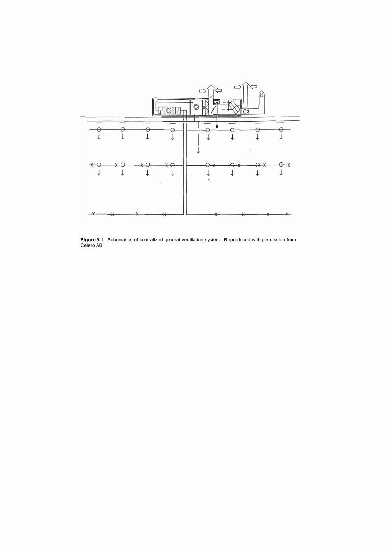
7/18/2019 Ventilation Guide
http://slidepdf.com/reader/full/ventilation-guide 152/223
Figure 9.1. Schematics of centralized general ventilation system. Reproduced with permission fromCelero AB.
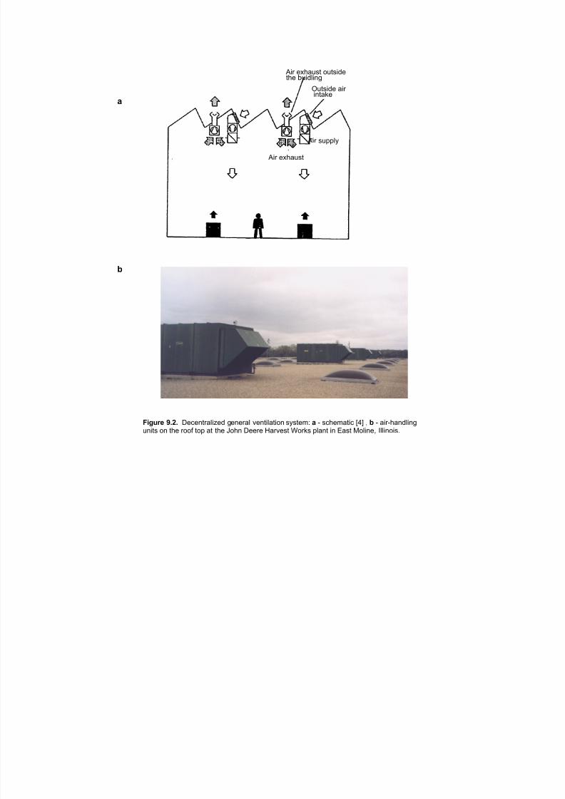
7/18/2019 Ventilation Guide
http://slidepdf.com/reader/full/ventilation-guide 153/223
"#$ %&'()*+ ,)+*#-% +'% .)#-/#01
2)+*#-% (#$#0+(3%
!
"#$ *)44/5
"#$ %&'()*+
"
#$%&'( *+,+ 6%7%0+$(/#8%- 1%0%$(/ 9%0+#/(+#,0 *5*+%:; ! < *7'%:(+#7 =>? @ " < (#$<'(0-/#01
)0#+* ,0 +'% $,,A +,4 (+ +'% B,'0 6%%$% C($9%*+ D,$3* 4/(0+ #0 E(*+ F,/#0%@ G//#0,#*H

7/18/2019 Ventilation Guide
http://slidepdf.com/reader/full/ventilation-guide 154/223
a
b
Figure 9.3. Roof mounted air handling unit: a - with a chilled water cooling coil and a direct fired
gas burner. Reproduced with permission from H.M. White, Inc.; b - with an indirect fired gasburner section. (Reproduced with permission from Toyota Manufacturing, Inc.
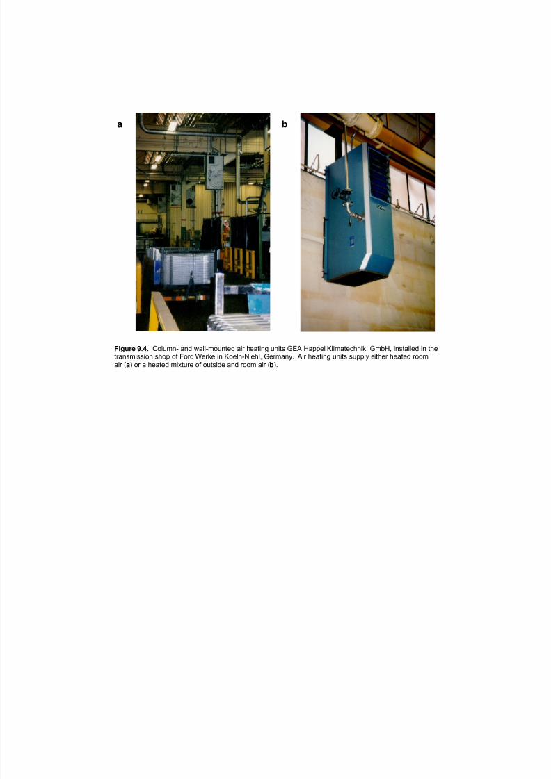
7/18/2019 Ventilation Guide
http://slidepdf.com/reader/full/ventilation-guide 155/223
" #
$%&'() *+,+ "#$%&'( )'* +)$$(&#%',-* )./ 0-),.'1 %'.,2 345 6)77-$ 8$.&),-90'.:; 3&<6; .'2,)$$-* .' ,0-,/)'2&.22.#' 20#7 #= >#/* ?-/:- .' 8#-$'(@.-0$; 3-/&)'AB 5./ 0-),.'1 %'.,2 2%77$A -.,0-/ 0-),-* /##&
)./ C"D #/ ) 0-),-* &.E,%/- #= #%,2.*- )'* /##& )./ C#DB
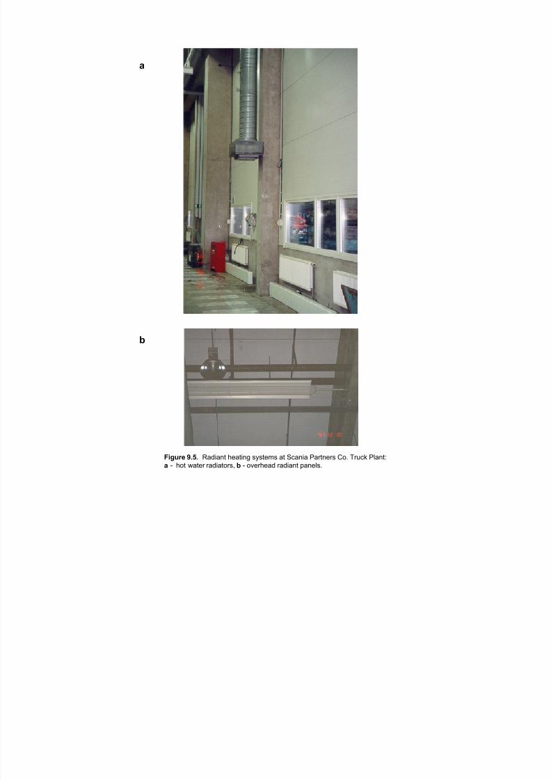
7/18/2019 Ventilation Guide
http://slidepdf.com/reader/full/ventilation-guide 156/223
!
"
#$%&'( *+,+ !"#$"%& ()"&$%* +,+&)-+ "& ./"%$" 0"1&%)1+ 234 516/7 08"%&9
! : (3& ;"&)1 1"#$"&31+< " : 3=)1()"# 1"#$"%& >"%)8+4
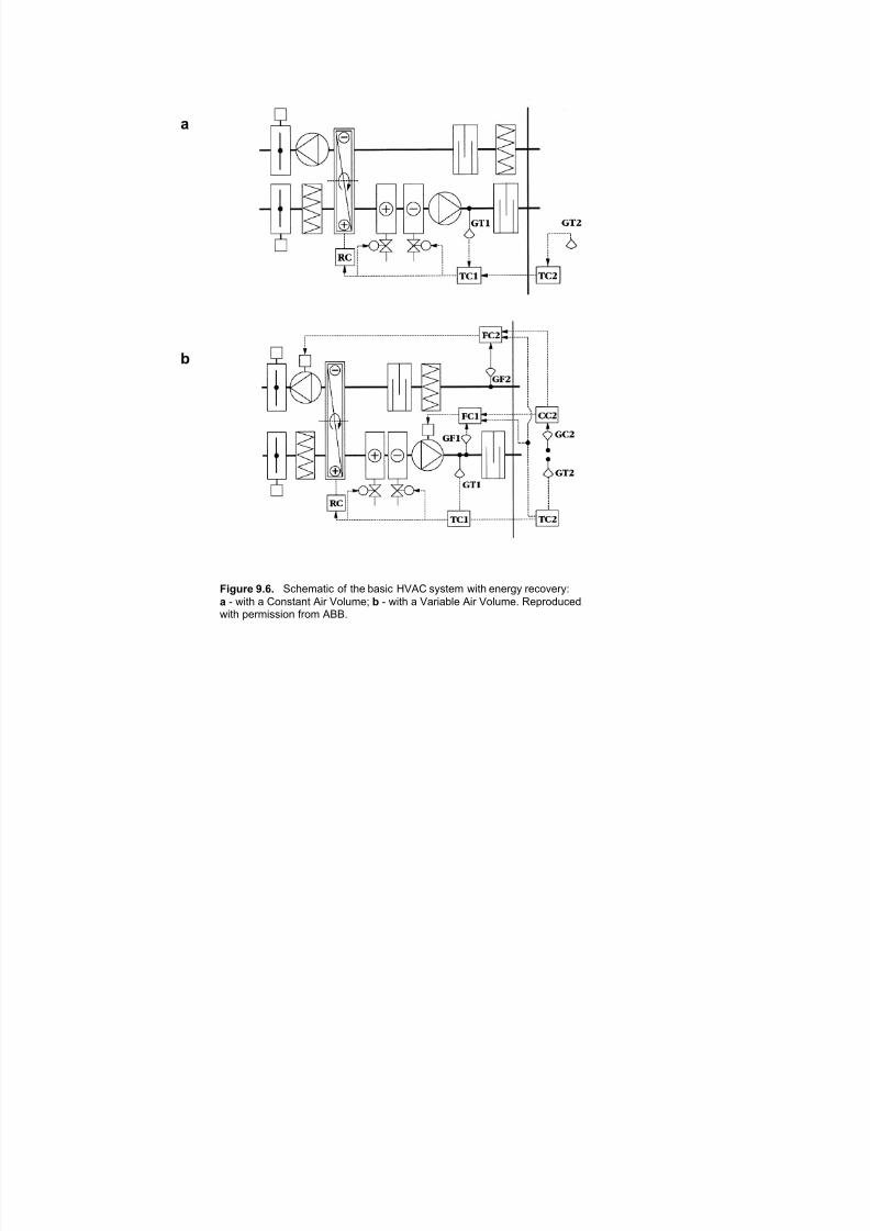
7/18/2019 Ventilation Guide
http://slidepdf.com/reader/full/ventilation-guide 157/223
a
b
Figure 9.6. Schematic of the basic HVAC system with energy recovery:
a - with a Constant Air Volume; b - with a Variable Air Volume. Reproducedwith permission from ABB.
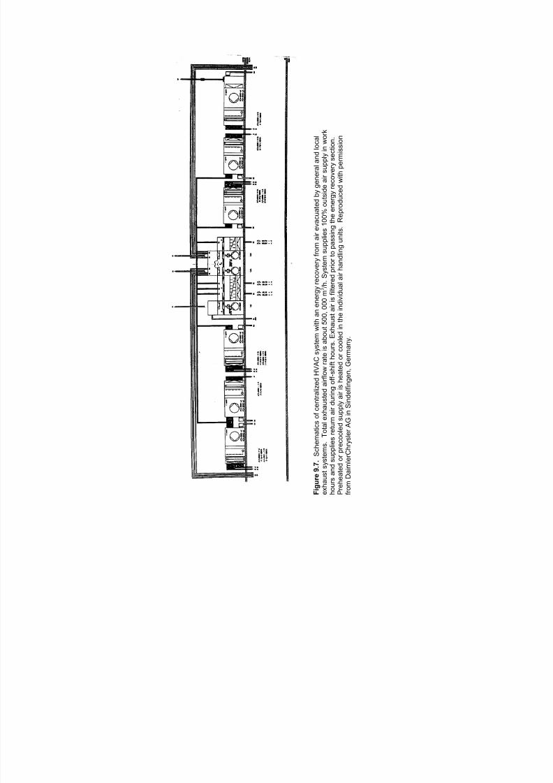
7/18/2019 Ventilation Guide
http://slidepdf.com/reader/full/ventilation-guide 158/223
F i g u r e
9 . 7 .
S c
h e m a
t i c s
o f c e n
t r a l i z e
d H V A C s y s
t e m
w i t h a n e n e r g y r e c o v e r y
f r o m
a i r e v a c u a
t e d b y g e n e r a
l a n
d l o c a
l
e x
h a u s
t s y s
t e m s .
T o
t a l
e x
h a u s
t e d a
i r f l o w r a
t e i s a
b o u
t 5 0 0
, 0 0 0 m
/ h .
S y s
t e m
s u p p
l i e s
1 0 0 %
o u
t s i d e a
i r s u p p
l y i n w o r k
3
h o u r s a n
d s u p p
l i e s r e
t u r n a
i r d u r i n g o
f f - s h i f t h o u r s .
E x
h a u s
t a
i r i s f i l t e r e
d p r i o r
t o p a s s
i n g
t h e e
n e r g y r e c o v e r y s e c
t i o n .
P r e
h e a
t e d o r p r e c o o
l e d
s u p p
l y a
i r i s h e a
t e d o r c o o
l e d i n t h e
i n d i v i d u a
l a
i r h a n
d l i n g u n
i t s .
R e p
r o d u c e
d w
i t h p e r m
i s s
i o n
f r o m
D a
i m l e r C
h r y s
l e r A
G
i n S i n d e
l f i n g e n ,
G e r m a n y .

7/18/2019 Ventilation Guide
http://slidepdf.com/reader/full/ventilation-guide 159/223
10. QUANTITY AND METHODS OF AIR SUPPLY.
10.1. Quantity of Supply Air.
Supply air rate must be sufficient to replace air exhausted by process ventilation and localexhausts, to provide dilution of contaminants, management of pressure and airflow inside thebuilding and between the building zones, and to provide the required thermal environment. Theamount of supplied air should be the maximum of that needed for temperature control, dilution,replacement and pressure management [5 ].
10.1.1. Dilution Ventilation Rate. The dilution ventilation rate for general ventilation shouldbe calculated for each of the contaminants produced and not captured by the localexhaust system. The ventilation rate required to maintain a concentration of acontaminant in the occupied zone within the target level (e.g., PEL, MAK, TLV, industryor company level) can be calculated from the following equation based on materialbalance in the premises [14]:
Qo
= Qexh
+G (1 - ) - Q
exh( C
o.z.- C
o )
K c ( Co.z.- Co )where
Qo = air supply rate;
Qexh = local ventilation exhaust rate;
G = rate of pollutant generation;
e = local ventilation capturing effectiveness;
C O Z . .
= average concentration of fume, gas, and particulates in the occupied zone air:
Co.z.
= Co.z.
- 2c
max
Average contaminant concentration value is used to calculate the outdoor air supply rateand is often confused with
C O Z . .
max
= maximum desired concentration of fume, gas, or particulates in the occupied
zone (e.g., equal to threshold limit value, TLV, MAK, etc.);
sc = standard deviation = ƒ(air supply method and air diffuser type, room size and
configuration, occupied zone obstruction with process equipment, etc);Co = concentration of fume, gas, particulates in the supply air;
Kc = contaminant removal efficiency:
Co.z.
- Co
K
c=
Cu.z.
- Co
7/18/2019 Ventilation Guide
http://slidepdf.com/reader/full/ventilation-guide 160/223
2
Cu.z. = concentration of fume, gas, particulates in the upper zone air (if air is evacuated
from this zone), or in the exhausted air. Contaminant removal efficiency coefficientsvalues Kc depend on the air supply method.The quantity of contaminant (fume, oil mist,
VOC, gas, or particulates), G, kg/h (lb/h), generated in the space can be calculatedusing one of the following equations:
G = R1 x Tprocess
where, R1 is a fume, oil mist, VOC, gas, particulate generation rate, kg/min (lb/min), and
Tprocess is an average contaminant release time per hour (e.g., arc time for the welding
process), min/hr;
G = R2 x U
where, R2 is a contaminant generation rate per production unit, kg/(production unit)
and U is an average production unit output, (e.g., production units per hour), in the givenprocess.
For welding process, total welding fume generation rates R1 is a fume (gas, particulate)
generation rate, kg/min (lb/min), and Tarc is an average arc time for the welding process
used, min/hr; R2 is a fume generation rate, kg (lb), per kg (lb) of electrodes used, and U
is an average electrode usage, kg/h (lb/h), in the given welding process. R1 and R2 and
percentage of the critical components in the fume for the typical welding processes arelisted in Tables 5.2 and 5.3. The average arc time for the typical welding processesbased on the Welding Institute of Canada data is presented in Figure 10.1. The averageelectrode usage U for different welding processes should be obtained from theproduction managers. However, as a rough estimate, the following data can be used[13]:
- Manual metal arc welding - 1 kg/h (2.2 lb/h); - Mechanized metal arc welding - 4 kg/h (8.8 lb/h); - Machine (robotics) submerged or arc welding - 4~6 kg/h (8.8~13.2 lb/h).
Capturing effectiveness of the local ventilation system, g , can be evaluated as 70~75% if no other information is available.
Concentration of fume, gas, or particles in the supplied air, Co, depends upon the ratio
between the outside and return air and the return air cleaning efficiency.
10.1.2. Supply air rate for temperature control. The air supply rate required toassimilate the surplus heat can be obtained from the following equation based on theheat balance in the premises
7/18/2019 Ventilation Guide
http://slidepdf.com/reader/full/ventilation-guide 161/223
3
Qo
= Qexh
+W - C
p Q
exh( t
o.z.- t
o )
C p K
t( t
o.z.- t
o )
where:W = surplus heat transferred to or generated in the premises;
Cp = specific heat;
t o.z.
, t o = average air temperature in the occupied zone and supplied air accordingly;
Kt = heat removal efficiency:
K t =
t u.z.
- t o
t o.z.
- t o
tu.z = air temperature in the upper zone of the premises (if air is evacuated from thiszone) or of the exhausted air. Heat removal efficiency coefficients values Kt depend on
the air supply method (Table 10.1).
10.1.3. Supply air for building pressurization. Building pressurization can be accomplished byproviding excess supply air (typically, ~10% or 0.5 ach for large buildings and ~20% or 1 ach for small buildings). The difference between capacities of general supply and local exhaust systemsis evacuated from the building by general exhaust system.
10.2. Air Supply Methods
Air supply into production facilities can be natural or mechanical. Natural ventilation systemsdriven by gravity forces and/or by wind effect, are still sometimes used in cold and moderate
climates for summer cooling. In hot climates natural ventilation systems are sometimes used for year round cooling. Natural ventilation systems are inefficient in large buildings.
The majority of ventilation systems in automotive production facilities are mechanical. The mostcommonly used methods of air supply into such facilities can be classified as:
· mixing,
· thermal displacement
· active displacement
· localized, and
· unidirectional flow.
Mixing-type air distribution. In mixing systems air is normally supplied into the space at velocities
much greater than those acceptable in the occupied zone. Supply air temperature can be above,below, or equal to the air temperature in the occupied zone, depending on the heating/coolingload. The supply air diffuser jet mixes with a room air by entrainment, which reduces air velocities and equalizes the air temperature. Properly selected and designed mixing air
7/18/2019 Ventilation Guide
http://slidepdf.com/reader/full/ventilation-guide 162/223
4
distribution creates relatively uniform air velocity, temperature, humidity, and air quality conditions
in the occupied zone and along the room height.
Typical mixing type air distribution methods used into automotive production can be classified as
{12]:
• air supply into the upper zone (h0 > 2/3 Hr) with air jets attached or not attached to the
ceiling (or as termed concentrated air supply) with the occupied zone ventilation by the
reverse air flow (Figure 10.2). Hr is the room height;
• air supply into the upper zone (h0 > 2/3 Hr) with horizontal (concentrated) air jets assisted
with an additional system of vertical and/or horizontal directing jets (Figure 10.3);
• air supply into the upper zone (h0 > 2/3 Hr) with inclined air jets (Figure 10.4) and the
occupied zone ventilated directly by the jets;
• air supply with inclined air jets through grilles or nozzles installed on walls and/or columns
at the height from 3 to 5m (10ft to 15ft) (Figure 10.5) from the floor level;
• air supply by conical or compact air jets through the air diffusers installed on the vertical
duct drops at the height from 3 to 5 m (10 to 20ft) (Figure 10.6);
Thermal displacement ventilation systems [15]. Air with a temperature slightly lower than thedesired room air temperature in the occupied is supplied from air outlets at low air velocities - 0.5
m/s (100 ft/min) or less. Under the influence of buoyancy forces cold air spreads along the floor,
and floods the lower zone of the room. The air close to the heat source is heated and rises
upward as a convective airstream. In the upper zone this stream spreads along the ceiling. The
lower part of the convective stream induces the cold air of the lower zone of the room, and the
upper part of the convective airstream induces the heated air of the upper zone of the room. The
height of the lower zone depends on the air volume discharged through the panels into the
occupied zone and on the amounts of convective heat discharged by the sources (Figure 10.7).
Typically the outlets are located at or near the floor level, and the supply air is directly introduced
to the occupied zone. In some applications of displacement ventilation (in computer rooms or in
hot industrial buildings) air can be supplied into the occupied zone through a false floor. In otherapplications supply air outlets can be located above the occupied zone. Returns are located at or
close to the ceiling/roof through which air is exhausted from the room.
Thermal displacement ventilation is preferable when contaminants are released in combination
with surplus heat and contaminated air is warmer and/or lighter than the surrounding air.
Thermal displacement ventilation system is not effective when air is supplied with a temperature
higher than the occupied zone air temperature. Thus, when heating is required, displacement
ventilation should be complimented by a hydraulic hot water/steam system with radiators or
convectors or with a fired-gas system with overhead radiant panels.
Active displacement ventilation systems [10,15]. Air with a temperature lower than the desired
room air temperature in the occupied zone is supplied through air diffusers located above the
occupied zone. Supply air velocity is lower compared to one with a mixing type air supply, but
higher, than with a thermal displacement ventilation. In the system shown in Figure 10.8., air
supplied through ducts with a specially punched nozzles suppresses polluted air of the occupied
zone and creates an overlying air cushion that displaces the contaminated air towards floor level
exhausts.
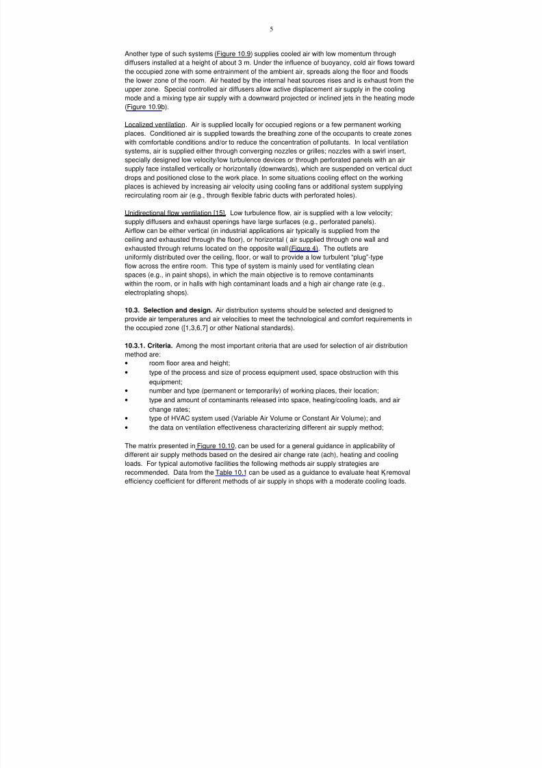
7/18/2019 Ventilation Guide
http://slidepdf.com/reader/full/ventilation-guide 163/223
5
Another type of such systems (Figure 10.9) supplies cooled air with low momentum through
diffusers installed at a height of about 3 m. Under the influence of buoyancy, cold air flows toward
the occupied zone with some entrainment of the ambient air, spreads along the floor and floods
the lower zone of the room. Air heated by the internal heat sources rises and is exhaust from the
upper zone. Special controlled air diffusers allow active displacement air supply in the cooling
mode and a mixing type air supply with a downward projected or inclined jets in the heating mode
(Figure 10.9b).
Localized ventilation . Air is supplied locally for occupied regions or a few permanent working
places. Conditioned air is supplied towards the breathing zone of the occupants to create zones
with comfortable conditions and/or to reduce the concentration of pollutants. In local ventilation
systems, air is supplied either through converging nozzles or grilles; nozzles with a swirl insert,
specially designed low velocity/low turbulence devices or through perforated panels with an air
supply face installed vertically or horizontally (downwards), which are suspended on vertical duct
drops and positioned close to the work place. In some situations cooling effect on the working
places is achieved by increasing air velocity using cooling fans or additional system supplying
recirculating room air (e.g., through flexible fabric ducts with perforated holes).
Unidirectional flow ventilation [15]. Low turbulence flow, air is supplied with a low velocity;
supply diffusers and exhaust openings have large surfaces (e.g., perforated panels).
Airflow can be either vertical (in industrial applications air typically is supplied from the
ceiling and exhausted through the floor), or horizontal ( air supplied through one wall and
exhausted through returns located on the opposite wall (Figure 4). The outlets are
uniformly distributed over the ceiling, floor, or wall to provide a low turbulent “plug”-type
flow across the entire room. This type of system is mainly used for ventilating clean
spaces (e.g., in paint shops), in which the main objective is to remove contaminants
within the room, or in halls with high contaminant loads and a high air change rate (e.g.,
electroplating shops).
10.3. Selection and design. Air distribution systems should be selected and designed toprovide air temperatures and air velocities to meet the technological and comfort requirements in
the occupied zone ([1,3,6,7] or other National standards).
10.3.1. Criteria. Among the most important criteria that are used for selection of air distribution
method are:
• room floor area and height;
• type of the process and size of process equipment used, space obstruction with this
equipment;
• number and type (permanent or temporarily) of working places, their location;
• type and amount of contaminants released into space, heating/cooling loads, and air
change rates;
• type of HVAC system used (Variable Air Volume or Constant Air Volume); and
• the data on ventilation effectiveness characterizing different air supply method;
The matrix presented in Figure 10.10, can be used for a general guidance in applicability of
different air supply methods based on the desired air change rate (ach), heating and cooling
loads. For typical automotive facilities the following methods air supply strategies are
recommended. Data from the Table 10.1 can be used as a guidance to evaluate heat Kt removal
efficiency coefficient for different methods of air supply in shops with a moderate cooling loads.
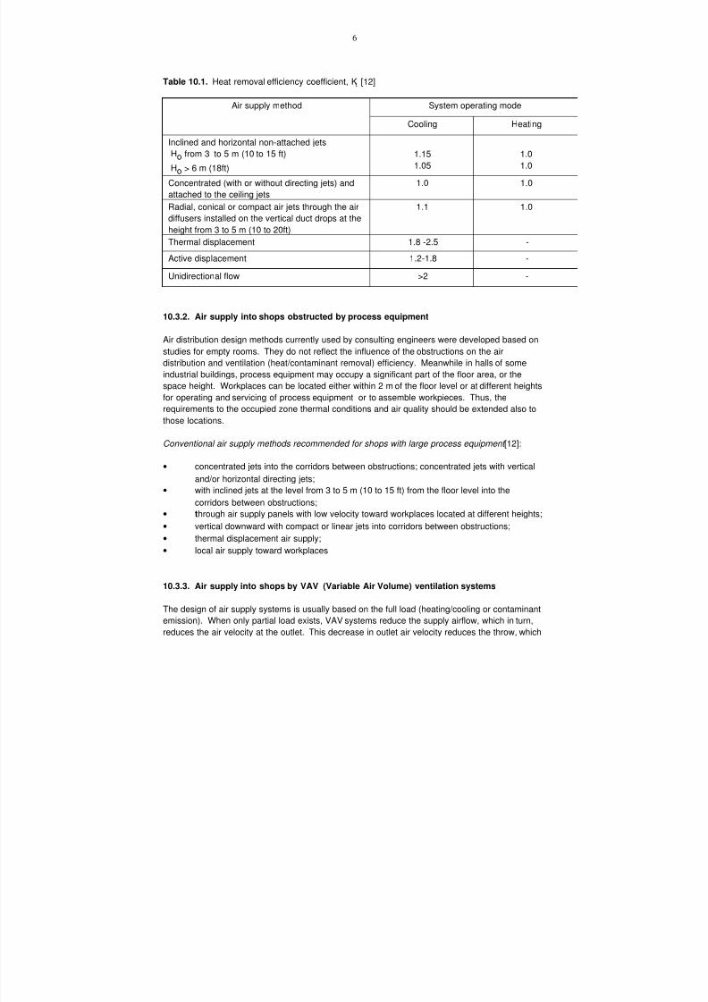
7/18/2019 Ventilation Guide
http://slidepdf.com/reader/full/ventilation-guide 164/223
6
Table 10.1. Heat removal efficiency coefficient, Kt. [12]
Air supply method System operating mode
Cooling Heating
Inclined and horizontal non-attached jets
Ho from 3 to 5 m (10 to 15 ft)
Ho > 6 m (18ft)
1.15
1.05
1.0
1.0
Concentrated (with or without directing jets) and
attached to the ceiling jets
1.0 1.0
Radial, conical or compact air jets through the air
diffusers installed on the vertical duct drops at the
height from 3 to 5 m (10 to 20ft)
1.1 1.0
Thermal displacement 1.8 -2.5 -
Active displacement 1.2-1.8 -
Unidirectional flow >2 -
10.3.2. Air supply into shops obstructed by process equipment
Air distribution design methods currently used by consulting engineers were developed based on
studies for empty rooms. They do not reflect the influence of the obstructions on the air
distribution and ventilation (heat/contaminant removal) efficiency. Meanwhile in halls of some
industrial buildings, process equipment may occupy a significant part of the floor area, or the
space height. Workplaces can be located either within 2 m of the floor level or at different heights
for operating and servicing of process equipment or to assemble workpieces. Thus, the
requirements to the occupied zone thermal conditions and air quality should be extended also tothose locations.
Conventional air supply methods recommended for shops with large process equipment [12]:
• concentrated jets into the corridors between obstructions; concentrated jets with vertical
and/or horizontal directing jets;
• with inclined jets at the level from 3 to 5 m (10 to 15 ft) from the floor level into the
corridors between obstructions;
• through air supply panels with low velocity toward workplaces located at different heights;
• vertical downward with compact or linear jets into corridors between obstructions;
• thermal displacement air supply;• local air supply toward workplaces
10.3.3. Air supply into shops by VAV (Variable Air Volume) ventilation systems
The design of air supply systems is usually based on the full load (heating/cooling or contaminant
emission). When only partial load exists, VAV systems reduce the supply airflow, which in turn,
reduces the air velocity at the outlet. This decrease in outlet air velocity reduces the throw, which

7/18/2019 Ventilation Guide
http://slidepdf.com/reader/full/ventilation-guide 165/223
7
may cause formation of areas with abnormal air motion and poorly ventilated zones [11].
Therefore, different operation modes of the system (airflow and initial temperature difference)
should be considered in designing a VAV system air distribution. Air supply through controlled
air diffusers (e.g., presented in Figure 10.11) and air supply systems with directing jets (Figure
10.3) may be recommended for the VAV systems when an air change rate is reduced by 75-85%
from the designed maximum value.

7/18/2019 Ventilation Guide
http://slidepdf.com/reader/full/ventilation-guide 166/223
8
10.4. Typical practices of air supply into auto manufacturing facilities
10.4.1. Machining shops.
• thermal displacement ventilation (Figure 10.12) and
• active displacement ventilation (Figure 10.13) and
• mixing air supply from the height 3 to 5 m (10 to 16 ft) (Figure 10.14)
10.4.2. Body shops and other shops with welding operations
• air supply with inclined jets from the height 3 to 5 m (10 to 16 ft) (Figure 10.15);
• concentrated air distribution into the upper zone with ventilating of the occupied zone by
return air flow (Figures 10.16);
• concentrated air distribution with horizontal and vertical or only vertical directing
jets (Figure 10.17);
• thermal displacement ventilation (Figure 10.18);
• air supply with inclined jets from truss space (Figure 10.19);.
For the spaces with obstructions higher than 3 m (10 ft), displacement ventilation and air
distribution with directing jets or air supply from the height of 3 to 5 m into the space betweenobstructions are recommended. However, displacement ventilation is not effective in body shops
or in welding shops with heavy usage of robotics operations: moving car bodies and robotics
arms distract temperature and contaminant stratification along room height and thus eliminate
advantages of displacement air supply.
In shops with arc welding operations, to maintain proper gas shielding air distribution systems
shall be designed such that the air velocities in the welding zone should not exceed:
· Shielded Metal Arc Welding (SMAW or MIG) - 1.2 m/s (240 fpm);
· Gas Metal Arc Welding (GMAW or rod/stick) - 0.5 m/s (100 fpm);
· Gas Tungsten Arc Welding (GTAW or TIG) - 0.3 m/s (60 fpm).
10.4.3. Assembly shops
• air supply directly to workplaces located along the conveyor (e.g., from small nozzles
connected in the duct installed directly above the conveyor (Figure 10.20a), or directly from
the duct with a perforation (Figure 10.20b);
• active displacement ventilation of the zones with uncontrolled vehicle exhausts, and touch-up
painting (Figure 10.21)
• air supply with inclined jets from the height from 3 to 5 m (10 to 16 ft);
• concentrated air supply into the upper zone with horizontal and vertical directing jets (Figure
10.22);
• active displacement ventilation through air diffusers installed at the height of ~3 m (Figure
10.23.)
10.4.4. Paint shops
• air supply through grilles from the height from 3 to 5 m (10 to 16 ft) (Figure 10.24a);
• thermal displacement ventilation into the paint shop building shell with air diffusers
located along paint booths (Figure 10.24b);
• unidirectional flow systems at the spot repair zone. Air is supplied by vertical downward
projected air flows through filter media panels installed at the height of 3-4 m (10-12 ft)
(Figure 10.25);

7/18/2019 Ventilation Guide
http://slidepdf.com/reader/full/ventilation-guide 167/223
9
• air supply directly to workplaces located along the conveyor (e.g., from small
nozzles (Figure 10.26);
• active displacement in the corrosion protection zone through perforated ducts (Figure
10.27).
10.5. References.
1. AFS. 1990. Hygieniska gränsvärden. AFS 1990:13. Publikationsservice. Solna,
Sweden. (in Swedish)
2. AIR-IX. 1987. Teollisuusilmanvaihdon suunnittelu. Kauppa-ja teollissusministerio.
Helsinki. (In Finnish)
3. ASHRAE. 1992. ASHRAE Standard 55-92. Thermal environmental conditions for
human occupancy. American Society of Heating Refrigerating and Air-Conditioning
Engineers. Atlanta, GA.
4. ASHRAE. 1997. ASHRAE Handbook. Fundamentals. American Society of Heating
Refrigerating and Air-Conditioning Engineers. Atlanta, GA.5. ASHRAE. 1999, ASHRAE Handbook. HVAC Applications. American Society of Heating
Refrigerating and Air-Conditioning Engineers. Atlanta, GA.
6. DIN. 1946. DIN 1946-Teil 2. Room ventilation technique, technical health principles.
VDI ventilation rules. Berlin. (in German)
7. ISO 7730. 1993. Moderate thermal environments - Determination of the PMV and PPD
indices and specification of the conditions for thermal comfort. International Standards
Organization. Geneva.
8. Kristensson, J.A., O.A. Lindqvist. 1993. Displacement ventilation systems in industrial
buildings. ASHRAE Transactions. V. 99(1). ASHRAE. Atlanta, GA.
9. LVIS. 1996. Ilmastointi. LVIS – 2000. Paintopaikka: Kausalan Kirjapaino Oy. (In Finish)
10. Lycke, J. 1999. General HPAC design methodology in Automotive Industry: Basic
Approach, Air Distribution Methods and Systems in Europe. Proceedings of theconference and workshop “Ventilation for Automotive Industry”. Detroit, April 1999.
Zhivov & Associates, L.L.C.
11. Zhivov, A.M. 1990. Variable Air Volume Ventilation Systems for Industrial
Buildings. Transactions of ASHRAE. V.96 (2).
12. Zhivov, A.M. 1992. Selection of general ventilation method for industrial
buildings . Presented at 1992 ASHRAE Annual Meeting (“Supply Air Systems for
Industrial Facilities” Seminar).
13. Zhivov A.M. 1993. Principles of Source Capturing and General Ventilation
Design for Welding Premises. Transaction of ASHRAE. V.99(1). American
Society of Heating Refrigerating and Air-Conditioning Engineers. Atlanta, GA.
14. Zhivov A.M. 1997. Development and evaluation of a practical model for
predicting room and air contaminant distribution. Report for the Institute forresearch in Construction (National Research Council, Canada). University of
Illinois. Urbana. IL.
15. Zhivov, A.M., P.V. Nielsen, G.L. Rikowski, Eu. O. Shilkrot. 2000. Displacement
Ventilation for Industrial Applications: Types, applications and design strategy.
HPAC Engineering. March 2000.

7/18/2019 Ventilation Guide
http://slidepdf.com/reader/full/ventilation-guide 168/223
Figure 10.1. Normal range of duty cycles for common welding processes andmodes of operation. Reproduced from [19].
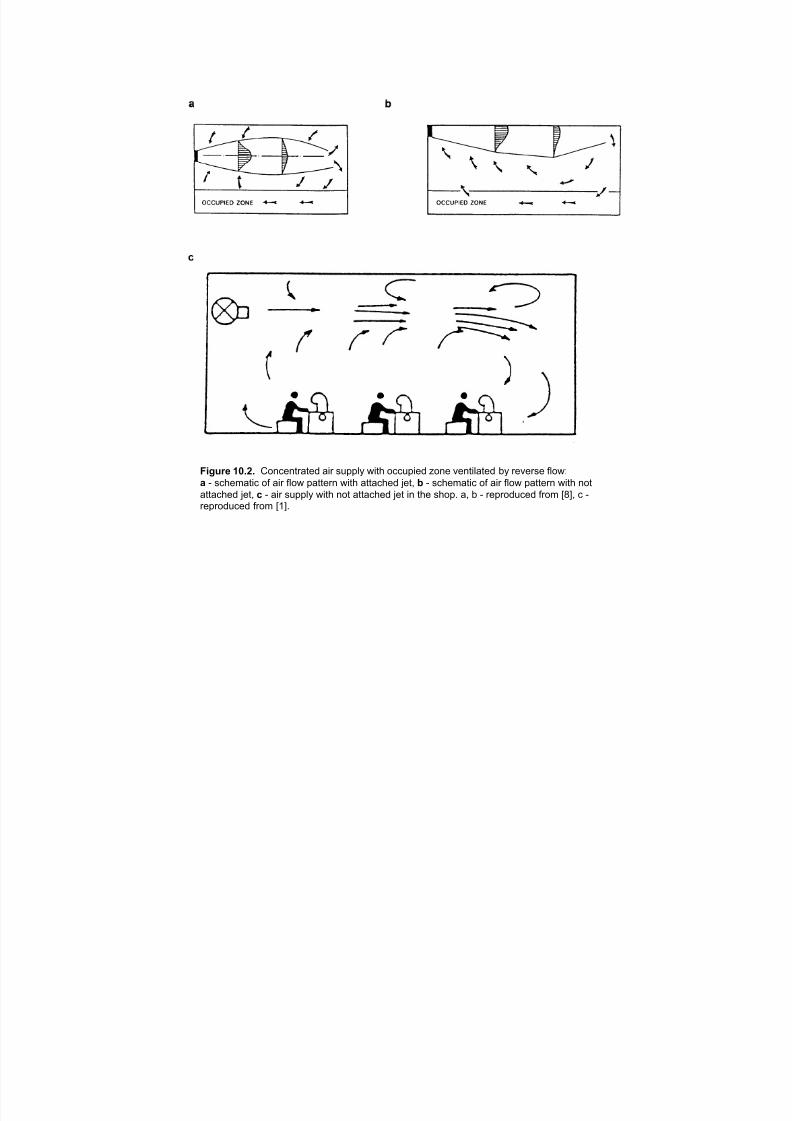
7/18/2019 Ventilation Guide
http://slidepdf.com/reader/full/ventilation-guide 169/223
Figure 10.2. Concentrated air supply with occupied zone ventilated by reverse flow:
a - schematic of air flow pattern with attached jet, b - schematic of air flow pattern with not
attached jet, c - air supply with not attached jet in the shop. a, b - reproduced from [8], c -reproduced from [1].

7/18/2019 Ventilation Guide
http://slidepdf.com/reader/full/ventilation-guide 170/223
Figure 10.3. Concentrated air supply with (a) horizontal and vertical directing jets,
(b) with only horizontal directing jets. Reproduced from [1].
7/18/2019 Ventilation Guide
http://slidepdf.com/reader/full/ventilation-guide 171/223
a b
Figure 10.4. Air supply with inclined jets from the upper zone of the ventilated space:
a - schematic of heated air supply; b - schematic of cooled air supply
Figure 10.5. Air supply with inclined jets from the height of 3 to 5m:
a - schematic of cooled air supply; b - schematic of heated air supply;
c - inclined air supply in mechanical shop. a and b - reproduced from [12],
c - reproduced from [2].

7/18/2019 Ventilation Guide
http://slidepdf.com/reader/full/ventilation-guide 172/223
Figure 10.6. Schematic of air supply by vertical jets through diffusersinstalled on vertical duct drops. Reproduced from [1].
Figure 10.7. Thermal displacement ventilation. Reproduced from [4].

7/18/2019 Ventilation Guide
http://slidepdf.com/reader/full/ventilation-guide 173/223
!"#$%& ()*+* !"#$%&'(") +, &"'(-$ .()/0&"$%$1' -$1'(0&'(+1 &(2 )3//04 '#2+35# /$2,+2&'$. .3"') (1%$"#&1("&0 )#+/6 7$/2+.3"$. 8('# /$2%())(+1 ,2+% 9::6
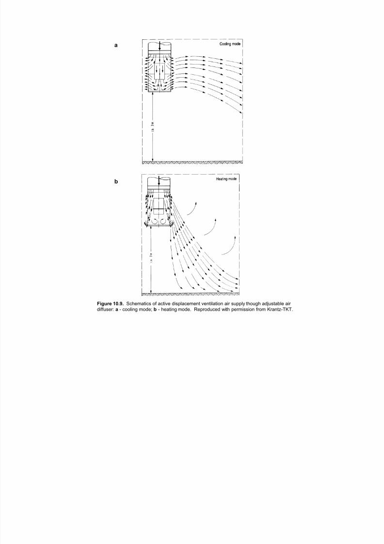
7/18/2019 Ventilation Guide
http://slidepdf.com/reader/full/ventilation-guide 174/223
a
b
Figure 10.9. Schematics of active displacement ventilation air supply though adjustable air
diffuser: a - cooling mode; b - heating mode. Reproduced with permission from Krantz-TKT.
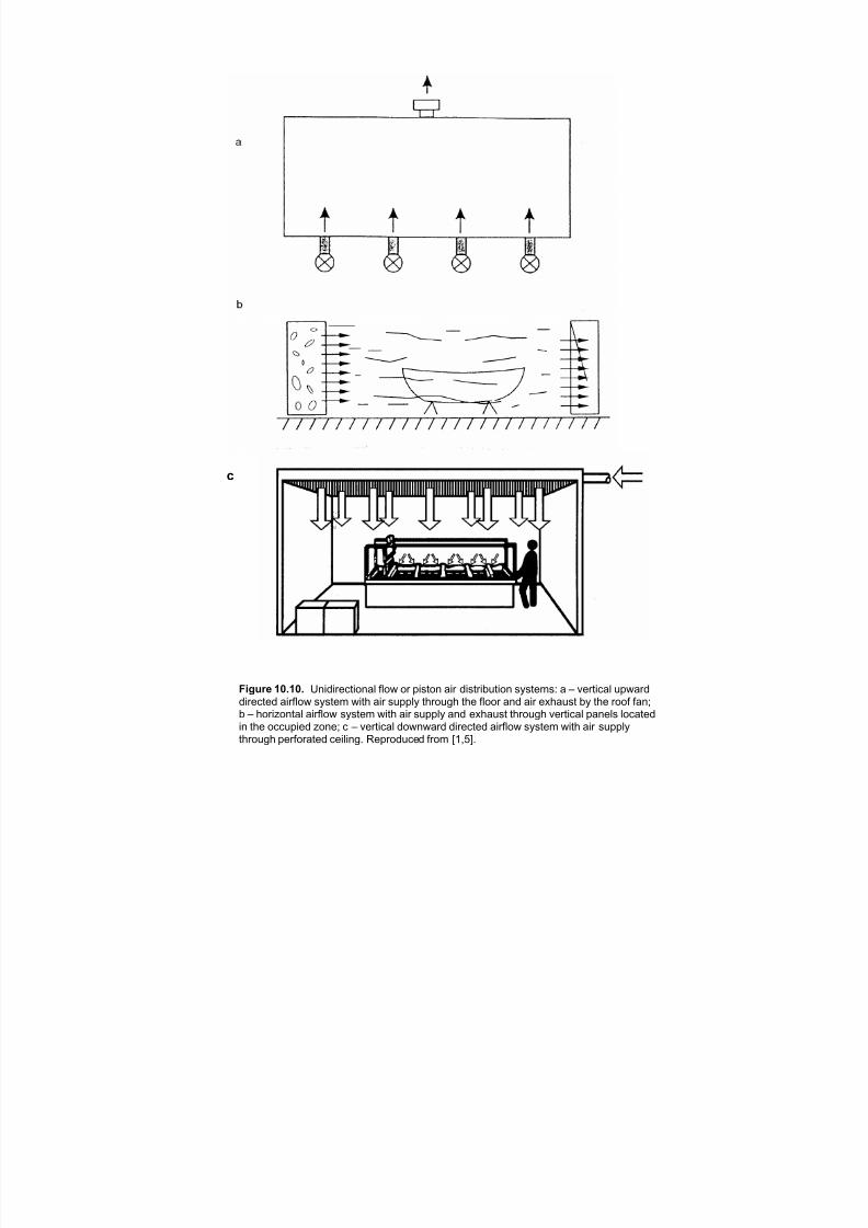
7/18/2019 Ventilation Guide
http://slidepdf.com/reader/full/ventilation-guide 175/223
c
Figure 10.10. Unidirectional flow or piston air distribution systems: a – vertical upwarddirected airflow system with air supply through the floor and air exhaust by the roof fan;b – horizontal airflow system with air supply and exhaust through vertical panels locatedin the occupied zone; c – vertical downward directed airflow system with air supplythrough perforated ceiling. Reproduced from [1,5].
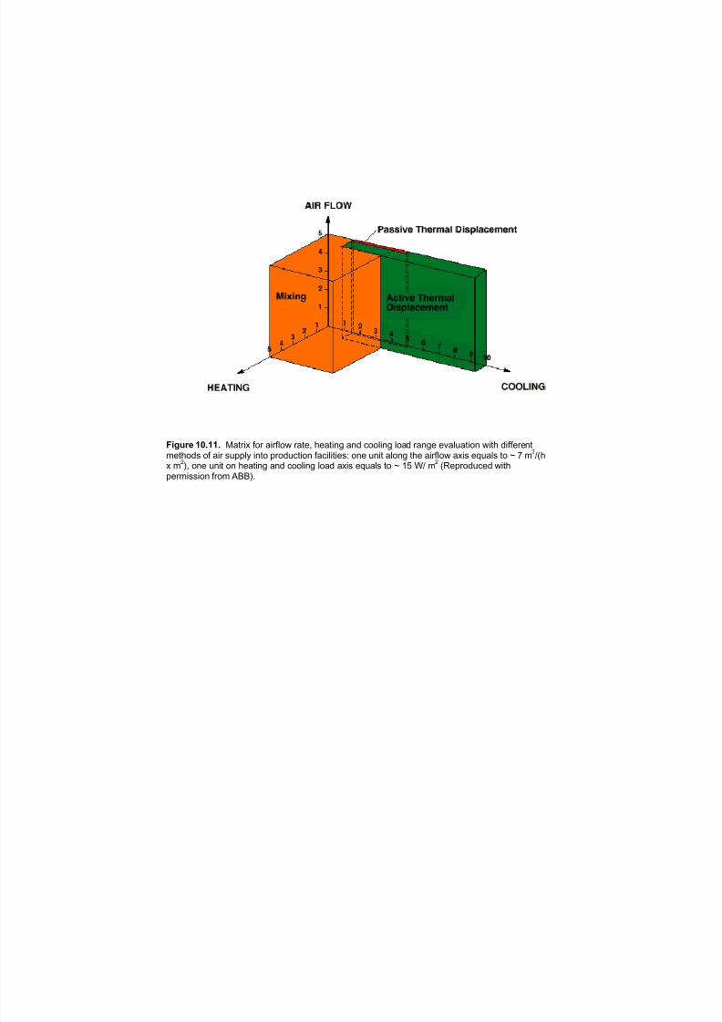
7/18/2019 Ventilation Guide
http://slidepdf.com/reader/full/ventilation-guide 176/223
Figure 10.11. Matrix for airflow rate, heating and cooling load range evaluation with differentmethods of air supply into production facilities: one unit along the airflow axis equals to ~ 7 m
3/(h
x m2), one unit on heating and cooling load axis equals to ~ 15 W/ m
2 (Reproduced with
permission from ABB).

7/18/2019 Ventilation Guide
http://slidepdf.com/reader/full/ventilation-guide 177/223
Bottom view
Figure 10.12. Air diffuser allowing a direction and jet characteristicscontrol for air supply with inclined jets in VAV systems. Reproduced from [7].

7/18/2019 Ventilation Guide
http://slidepdf.com/reader/full/ventilation-guide 178/223
!"#$%& ()*(+* !"#$%&' )*+,'&-#%#./ &*$ +0,,'1 *./2 /"# "&$)#.*.3 &$#& 24 %&-"*.*.3+"2, &/ 5-&.*& 6&$/.#$+ !$0-7 %&.04&-/0$*.3 ,'&./ *. 58)#$/9':#; 5<#)#.= >?? @'22$%&+/#$ +1+/#% +0,,'*#+ -2.)*/*2.#) &*$ /"$203" 4'22$A%20./#) &*$ /#$%*.&'+<*/" & +0,,'1 &*$ /#%,#$&/0$# B C D#'2< /"# 2--0,*#) E2.# &*$ /#%,#$&/0$#= !"# +1+/#%2
-2%D*.#+ & FGGH 20/+*)# &*$ +0,,'1 <*/" "#&/*.3 &.) -22'*.3 #.#$31 $#-2I#$1 *. & $2/&$1
"#&/ #J-"&.3#$=

7/18/2019 Ventilation Guide
http://slidepdf.com/reader/full/ventilation-guide 179/223
!"#$%& ()*(+* "#$%&' (%)*+,#'-'.$ ,%/ )0**+1 %.$2 $3' -,#3%.%.4 3,++ 25 $3' 678 9.4%.' :+,.$ %. ;$,1'/< "0)$/%,= "%/ %) (%)$/%>0$'( 5/2- $3' 3'%43$ 25 ? @ - $3/2043 #%/#0+,/ *'/52/,$'( A/,.$BCDAD 20$+'$) E"CF=;0**+1 ,%/ %) */'$/',$'( %. 3',$ 'G#3,.4'/ #20*+'( H%$3 $3' #'.$/,+%B'( 2%+ -%)$ #2.$/2+ )1)$'-=
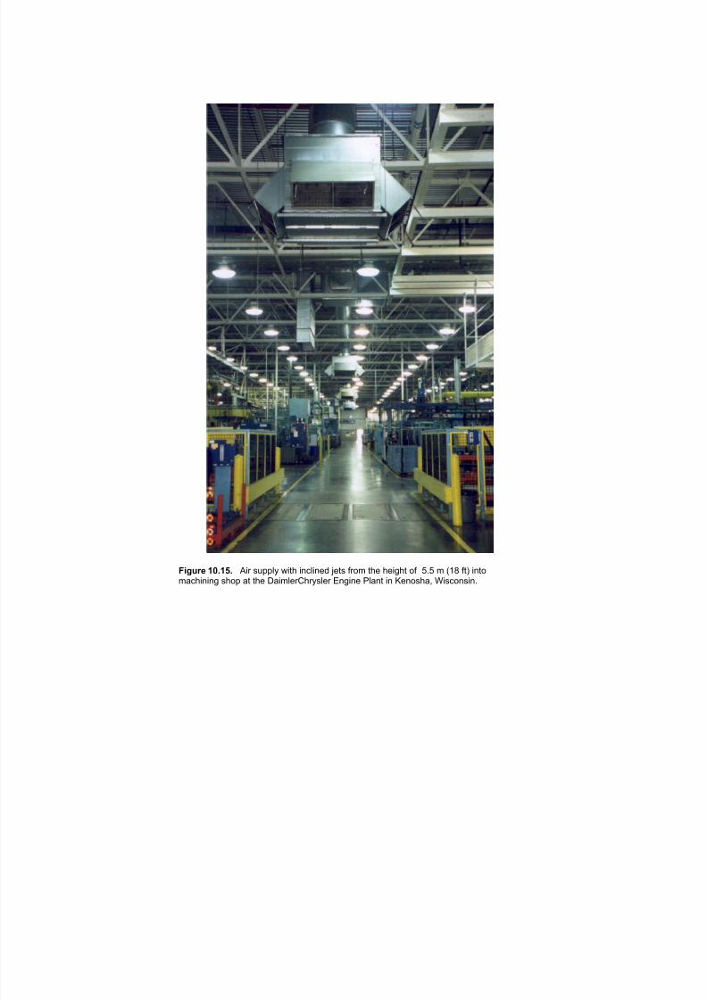
7/18/2019 Ventilation Guide
http://slidepdf.com/reader/full/ventilation-guide 180/223
Figure 10.15. Air supply with inclined jets from the height of 5.5 m (18 ft) intomachining shop at the DaimlerChrysler Engine Plant in Kenosha, Wisconsin.
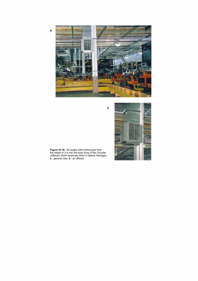
7/18/2019 Ventilation Guide
http://slidepdf.com/reader/full/ventilation-guide 181/223
!
!
"#$%&' )*+),+ "#$ %&''() *#+, #-.(#-/0 1/+% 2$34
+,/ ,/#5,+ 32 6 4 #-+3 +,/ 730) %,3' 32 +,/ 8,$)%(/$ 9/22/$%3- :3$+, "%%/47() ;(<-+ #- =/+$3#+> ?#.,#5<-@! A 5/-/$<( B#/*> - A <#$ 0#22&%/$C

7/18/2019 Ventilation Guide
http://slidepdf.com/reader/full/ventilation-guide 182/223
!"#$%& ()*(+* "#$%&'(( )*+ (#,,&- .*%/ +)0*)& 1'%( *2%3 %/' #,,'+ 432' 35 %/' .'&0*26(/3, )% %/' 73/2 "''+' 8)+9'(% :3+;( ,&)2% *2 <3&*2'= >&&*23*(?
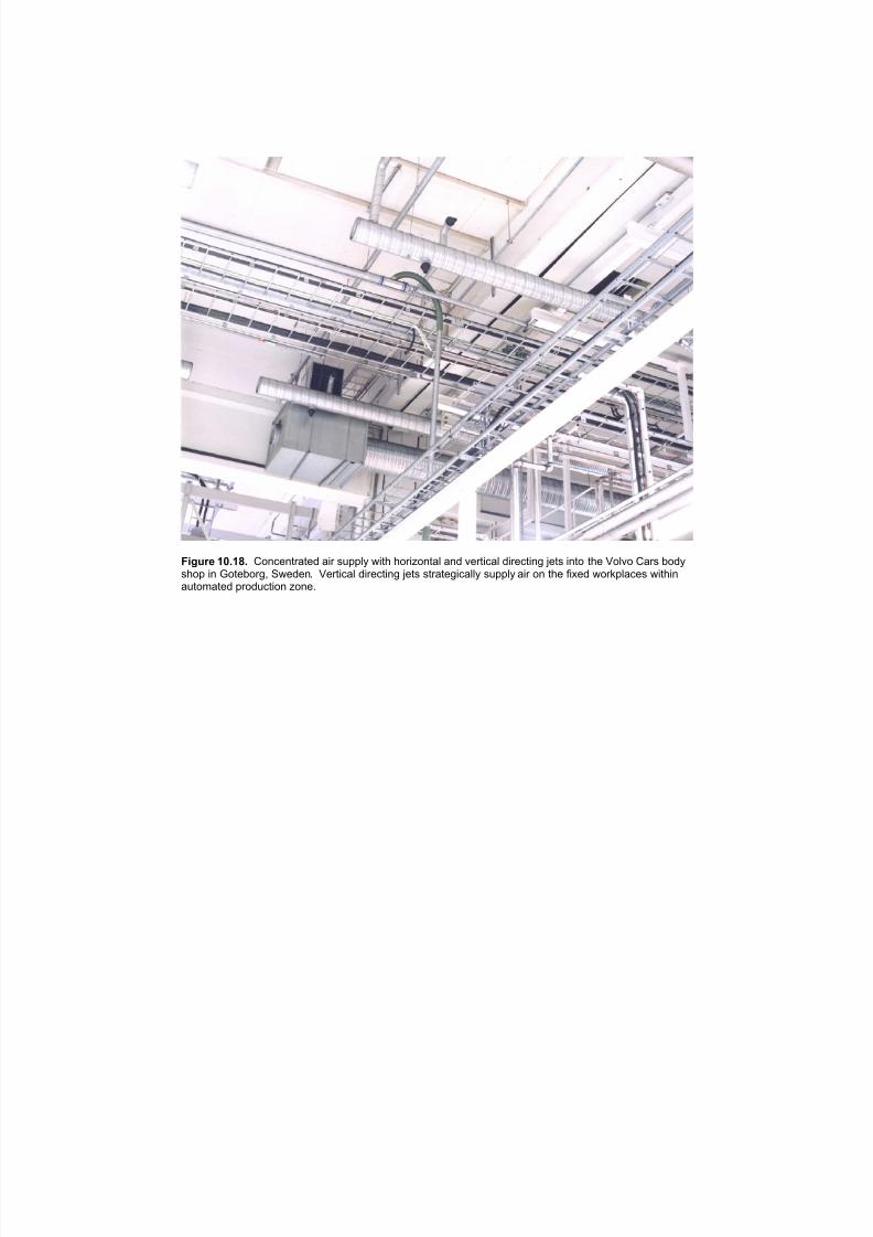
7/18/2019 Ventilation Guide
http://slidepdf.com/reader/full/ventilation-guide 183/223
Figure 10.18. Concentrated air supply with horizontal and vertical directing jets into the Volvo Cars bodyshop in Goteborg, Sweden. Vertical directing jets strategically supply air on the fixed workplaces withinautomated production zone.

7/18/2019 Ventilation Guide
http://slidepdf.com/reader/full/ventilation-guide 184/223
Figure 10.19. Thermal displacement ventilation in the welding shopof Scania Cabin Plant in Oskarshamn, Sweden.

7/18/2019 Ventilation Guide
http://slidepdf.com/reader/full/ventilation-guide 185/223
Figure 10.20. Air supply with inclined jets from the truss space into the body
shop of the DaimlerChrysler Windsor Assembly plant in Windsor, Ontario.
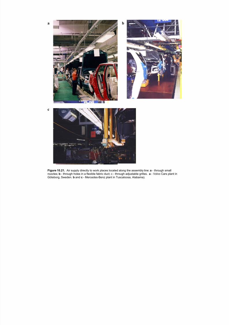
7/18/2019 Ventilation Guide
http://slidepdf.com/reader/full/ventilation-guide 186/223
a b
c
Figure 10.21. Air supply directly to work places located along the assembly line: a - through small
nozzles; b - through holes in a flexible fabric duct; c - through adjustable grilles. a - Volvo Cars plant in
Göteborg, Sweden, b and c - Mercedes-Benz plant in Tuscaloosa, Alabama).
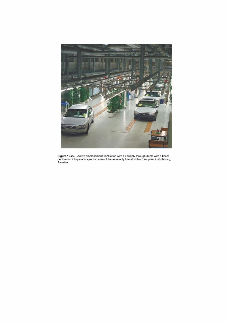
7/18/2019 Ventilation Guide
http://slidepdf.com/reader/full/ventilation-guide 187/223
Figure 10.22. Active displacement ventilation with air supply through ducts with a linear perforation into paint inspection area of the assembly line at Volvo Cars plant in Goteborg,Sweden.
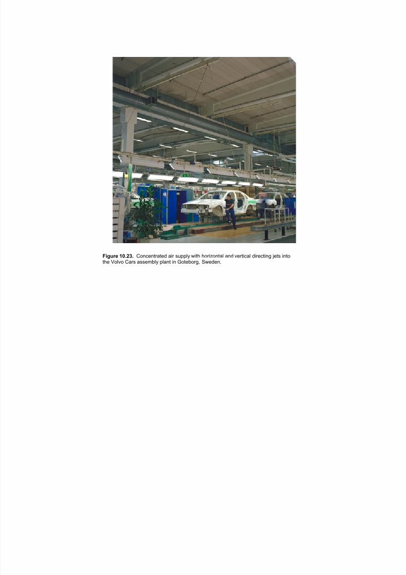
7/18/2019 Ventilation Guide
http://slidepdf.com/reader/full/ventilation-guide 188/223
Figure 10.23. Concentrated air supply with horizontal and vertical directing jets intothe Volvo Cars assembly plant in Goteborg, Sweden.

7/18/2019 Ventilation Guide
http://slidepdf.com/reader/full/ventilation-guide 189/223
a
b
Figure 10.24. Active displacement airsupply into VW assembly shop (a). Air is
distributed from the height of ~ 3m throughcircular perforated Krantz-TKT outlets (b).Reproduced with permission from Krantz-TKT.
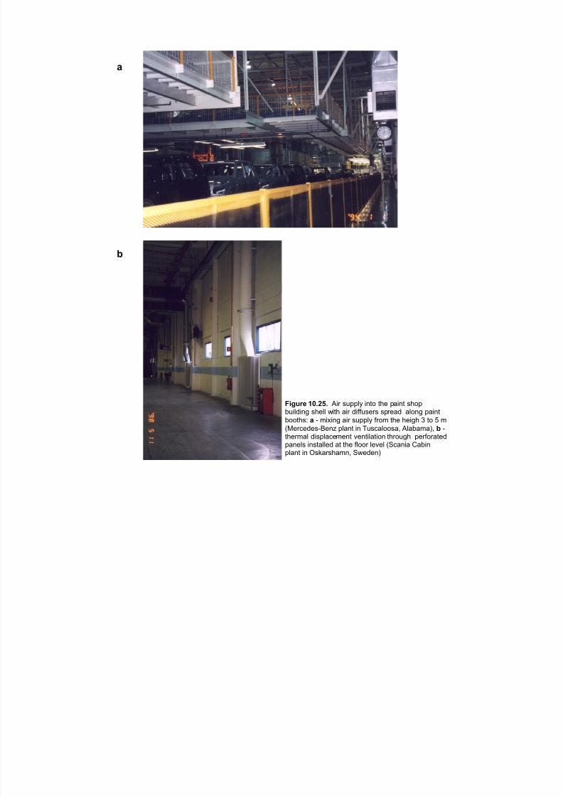
7/18/2019 Ventilation Guide
http://slidepdf.com/reader/full/ventilation-guide 190/223
!
"
$%&'() *+,-., "#$ %&''() #*+, +-. '/#*+ %-,'0&#(1#*2 %-.(( 3#+- /#$ 1#44&%.$% %'$./1 /(,*2 '/#*+
0,,+-%5 ! 6 7#8#*2 /#$ %&''() 4$,7 +-. -.#2- 9 +, : 7
;<.$=.1.%6>.*? '(/*+ #* @&%=/(,,%/A "(/0/7/BA " 6+-.$7/( 1#%'(/=.7.*+ C.*+#(/+#,* +-$,&2- '.$4,$/+.1'/*.(% #*%+/((.1 /+ +-. 4(,,$ (.C.( ;D=/*#/ E/0#*'(/*+ #* F%G/$%-/7*A D3.1.*B

7/18/2019 Ventilation Guide
http://slidepdf.com/reader/full/ventilation-guide 191/223
Figure 10.26. Vertical unidirectional flow ventilation in spot repair booths with air supply and return
through the filter media panels. Supply panels (a, c) are incorporated into the ceiling and return panels
are close to (b) or at the (d) floor level. a and b - Ford Motor Co. Assembly plant in Minsk, Belarus; c
and d - Mercedes-Benz plant in Tuscaloosa, Alabama.
a c
db
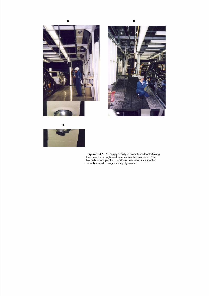
7/18/2019 Ventilation Guide
http://slidepdf.com/reader/full/ventilation-guide 192/223
a b
c
Figure 10.27. Air supply directly to workplaces located alongthe conveyor through small nozzles into the paint shop of the
Mercedes-Benz plant in Tuscaloosa, Alabama: a - inspectionzone, b - repair zone, c - air supply nozzle.
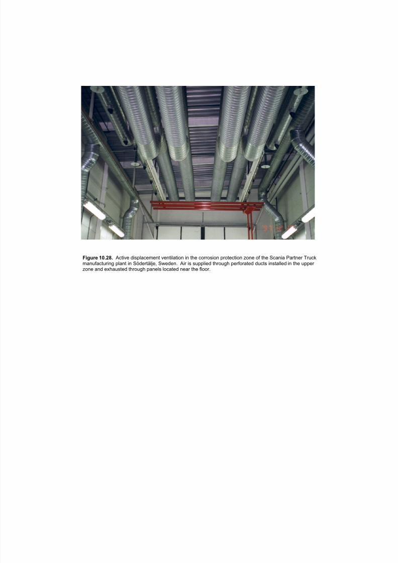
7/18/2019 Ventilation Guide
http://slidepdf.com/reader/full/ventilation-guide 193/223
Figure 10.28. Active displacement ventilation in the corrosion protection zone of the Scania Partner Truckmanufacturing plant in Södertälje, Sweden. Air is supplied through perforated ducts installed in the upper zone and exhausted through panels located near the floor.
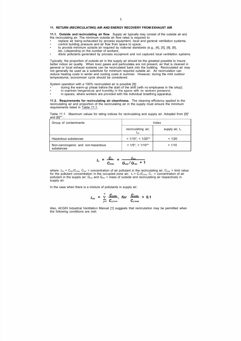
7/18/2019 Ventilation Guide
http://slidepdf.com/reader/full/ventilation-guide 194/223
1
11. RETURN (RECIRCULATING) AIR AND ENERGY RECOVERY FROM EXHAUST AIR
11.1. Outside and recirculating air flow. Supply air typically may consist of the outside air andthe recirculating air. The minimum outside air flow rates is required to:• replace air being exhausted by process equipment, local and general ventilation systems;• control building pressure and air flow from space to space;• to provide minimum outside air required by national standards (e.g., [4], [5], [6], [9],
etc..);depending on the number of workers;• dilute pollutants generated by process equipment and not captured local ventilation systems. Typically, the proportion of outside air in the supply air should be the greatest possible to insurebetter indoor air quality. When toxic gases and particulates are not present, air that is cleaned ingeneral or local exhaust systems can be recirculated back into the building. Recirculated air maynot generally be used as a substitute for minimum required outside air. Air recirculation canreduce heating costs in winter and cooling costs in summer. However, during the mild outdoor temperatures, economizer cycle should be considered.
System operation with a 100% recirculated air is possible [9]:• during the warm-up phase before the start of the shift (with no employees in the shop);
• to maintain temperature and humidity in the space with no workers presence;• in spaces, where workers are provided with the individual breathing apparatus.
11.2. Requirements for recirculating air cleanliness. The cleaning efficiency applied to therecirculating air and proportion of the recirculating air in the supply must ensure the minimumrequirements listed in Table 11.1. Table 11.1. Maximum values for rating indices for recirculating and supply air. Adopted from [9]*and [6]** .
IndexGroup of contaminants
recirculating air,Irec
supply air, Io
Hazardous substances < 1/10*, < 1/20** < 1/20
Non-carcinogenic and non-hazardoussubstances
< 1/5*, < 1/10** < 1/10
o
o rec
out rec
I = C
C = I
G / G +max
1
where: Irec = Crec/Cmax, Crec = concentration of air pollutant in the recirculating air, Cmax = limit valuefor the pollutant concentration in the occupied zone air; Io = Co/Cmax, Co = concentration of air pollutant in the supply air; Gout and Grec = mass of outside and recirculating air respectively insupply air.
In the case when there is a mixture of pollutants in supply air:
rec
j =1
n j.rec
j.
j.rec
j.
I =C
C , for
C
C >S
max max
0.1
Also, ACGIH Industrial Ventilation Manual [1] suggests that recirculation may be permitted whenthe following conditions are met:
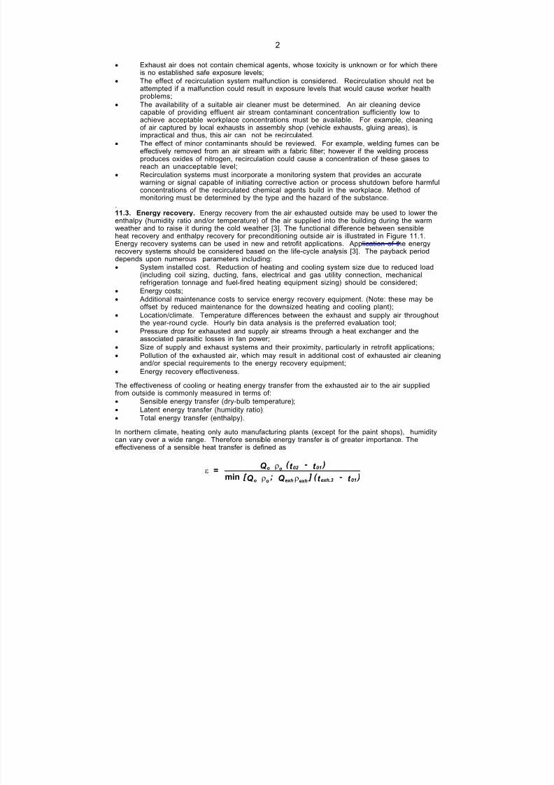
7/18/2019 Ventilation Guide
http://slidepdf.com/reader/full/ventilation-guide 195/223
2
· Exhaust air does not contain chemical agents, whose toxicity is unknown or for which thereis no established safe exposure levels;
· The effect of recirculation system malfunction is considered. Recirculation should not beattempted if a malfunction could result in exposure levels that would cause worker healthproblems;
· The availability of a suitable air cleaner must be determined. An air cleaning devicecapable of providing effluent air stream contaminant concentration sufficiently low toachieve acceptable workplace concentrations must be available. For example, cleaningof air captured by local exhausts in assembly shop (vehicle exhausts, gluing areas), isimpractical and thus, this air can not be recirculated.
· The effect of minor contaminants should be reviewed. For example, welding fumes can beeffectively removed from an air stream with a fabric filter; however if the welding processproduces oxides of nitrogen, recirculation could cause a concentration of these gases toreach an unacceptable level;
· Recirculation systems must incorporate a monitoring system that provides an accuratewarning or signal capable of initiating corrective action or process shutdown before harmfulconcentrations of the recirculated chemical agents build in the workplace. Method of monitoring must be determined by the type and the hazard of the substance.
.
11.3. Energy recovery. Energy recovery from the air exhausted outside may be used to lower theenthalpy (humidity ratio and/or temperature) of the air supplied into the building during the warmweather and to raise it during the cold weather [3]. The functional difference between sensibleheat recovery and enthalpy recovery for preconditioning outside air is illustr ated in Figur e 11.1.Energy recovery systems can be used in new and retrofit applications. Application of the energyrecovery systems should be considered based on the life-cycle analysis [3]. The payback perioddepends upon numerous parameters including:
· System installed cost. Reduction of heating and cooling system size due to reduced load(including coil sizing, ducting, fans, electrical and gas utility connection, mechanicalrefrigeration tonnage and fuel-fired heating equipment sizing) should be considered;
· Energy costs;
· Additional maintenance costs to service energy recovery equipment. (Note: these may beoffset by reduced maintenance for the downsized heating and cooling plant);
· Location/climate. Temperature differences between the exhaust and supply air throughoutthe year-round cycle. Hourly bin data analysis is the preferred evaluation tool;
· Pressure drop for exhausted and supply air streams through a heat exchanger and theassociated parasitic losses in fan power;
· Size of supply and exhaust systems and their proximity, particularly in retrofit applications;
· Pollution of the exhausted air, which may result in additional cost of exhausted air cleaningand/or special requirements to the energy recovery equipment;
· Energy recovery effectiveness.
The effectiveness of cooling or heating energy transfer from the exhausted air to the air suppliedfrom outside is commonly measured in terms of:
· Sensible energy transfer (dry-bulb temperature);
· Latent energy transfer (humidity ratio);
· Total energy transfer (enthalpy).
In northern climate, heating only auto manufacturing plants (except for the paint shops), humiditycan vary over a wide range. Therefore sensible energy transfer is of greater importance. Theeffectiveness of a sensible heat transfer is defined as
er
r r =
Q ( t - t )
[ Q ; Q ] ( t - t )
o o 02 01
o o exh exh exh.3 01min

7/18/2019 Ventilation Guide
http://slidepdf.com/reader/full/ventilation-guide 196/223
where, Qo = supply air flow rate, Qexh = exhaust airflow rate; _o = supply air density; _exh = exhaust airdensity; t01 supply air entering temperature; t02 = supply air leaving temperature; texh.3 = exhaust airentering temperature.
Heating or cooling energy recovery effectiveness depends upon the type of the energy recoverysystem used and vary between 35% and 80% [9]. The most common energy recovery devices used inindustrial ventilation systems are summarized in Table 11.2. Those with higher latent (and thusgreater enthalpy) effectiveness will be more important in warm, humid climates or where tighter
control of indoor conditions are significant to quality control and production efficiency.
In cost/benefit analysis, the following options may be compared:• minimum outside air mixed with a cleaned recirculated air supply;• minimum outside air with energy recovery mixed with a cleaned recirculated air supply;• 100% outside air supply and air exhaust outside the building without energy recovery;• 100% outside air supply with energy recovery from exhaust air and processes.
The following areas in auto manufacturing plans may be considered for energy recovery systemsapplication based on the results of the life-cost analysis:• Machining shops. Energy recovery from the air extracted by centralized exhaust systems can
be used for pre-heating/pre-cooling of supply air. Supply and exhaust systems shall haveapproximately equal air flow rates and located in proximity to each other. Exhausted air
should be filtered to remove oil mist prior to entering the energy recovery device;• Body shops. Energy recovery from the air extracted by large size hoods over robotics
welding areas, and air extracted by centralized exhaust systems can be used for pre-heating/pre-cooling of supply air. Supply and exhaust systems shall have approximately equalair flow rates and located in proximity to each other. Exhausted air should be filtered toremove particulates prior to entering the energy recovery device;
• Paint shops. Pre-heating/pre-cooling of air supplied to the building using energy recoveredfrom the process;
• Assembly shops. Energy recovery from exhausted air is used to precondition outside air tomeet minimum outside air rate requirements.
Figure 11.2. shows examples of general ventilation systems with energy recovery for body shops andmachining shops. The sample data resulted from the economical analysis of some typical situations are
summarized in Tables 11.3 and 11.4, and can be used only for the preliminary evaluation.
11.4. References
1. ACGIH. 1998. Industrial Ventilation. A Manual of Recommended Practice. 23 edition.American Conference of Government Industrial Hygienists. Cincinnati, OH.
2. AFS 1996:2. 1996. Occupational Exposure Limit Values. The Swedish National Board of Occupational
Safety and Health.
3. ASHRAE. 2000. ASHRAE Handbook. HVAC Systems and Equipment. American Societyof Heating, Refrigerating and Air Conditioning Engineers, Inc. Atlanta, GA.
4. ASHRAE. 1989. Ventilation for Acceptable Indoor Air Quality. ASHRAE/ANSI Standard62-1989. American Society of Heating, Refrigerating and Air Conditioning Engineers, Inc.Atlanta, GA.
5. ASR. 1975. Workplace Regulations ASR 5. Verordung über Arbeitstätten,Arbeistättenverordnung (ArbStättV) vom 20.03.1975. BGBI. I 1975, S. 729.
6. AFS 1993:5. Ventilation och Luftkvalitet. April, 29, 1993. Sweden.7. Celero Support AB. 1998. General Description of ventilation systems. Private
communications with Mr. Sten-Arne H_kansson.8. Gores, St. 1997. Lufttechnische Gesamtkonzerpte für kühlschmierstaffbelastete Industriehallen. VDI
Berichte 1326.
9. VDI 2262. 1994. Workplace air. Reduction of Exposure to Air Pollutants. VentilationTechnical Measures. Part 3. VDI-Hanbuch Reinhaultung. Düsseldorf.
10. Volvo Truck AB. 1997. Tekniska Specifikationer. VVS-installationer för kontorsbyggnad.Göteborg. 1997-09-01.
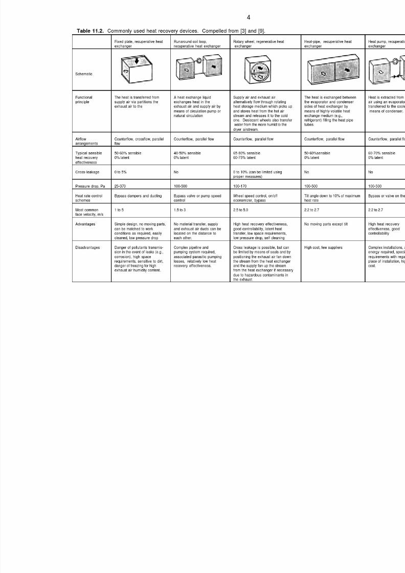
7/18/2019 Ventilation Guide
http://slidepdf.com/reader/full/ventilation-guide 197/223

7/18/2019 Ventilation Guide
http://slidepdf.com/reader/full/ventilation-guide 198/223
5
Table 11.3. Sample economic analysis for energy recovery ventilation at 25,000 CFM,impacts on first cost
Location _ Detroit, MI Dayton, OH Greenville, SC Tuscaloosa, AL Toronto, ON
ERV @$3/cfmCooling @$2000/ton
$75,000-71,400
$3,600
$75,000-71,400
$3,600
$75,000-84,000
$9,000
$75,000-137,400
$62,400
$85,000-71,600
$13,400
Table 11.4. Sample Economic Analysis for Energy Recovery Ventilation at 25,000 CFM,simple paybacks
Location _ Detroit, MI Dayton, OH Greenville, SC Tuscaloosa, AL Toronto, ON
1st cost:ops cost:payback1shift
$3,600($6,577)
6 mo.
$3,600($5,757)
7 mo.
($9,000)($3,576)instant
($62,400)($3,781)instant
$13,000($7,228)<2 years
1st
cost:ops cost:payback2 shifts
$3,600($12,645)
3 mo.
$3,600($10,735)
4 mo.
($9,000)($6,366)instant
($62,400)($5,563)instant
$13,000($13,498)
<1 year
1st
cost:ops cost:payback3 shifts
$3,600($19,795)
2 mo.
$3,600($16,894)
3 mo.
($9,000)($9,365)instant
($62,400)($7,886)instant
$13,000($20,971)
7 mo.
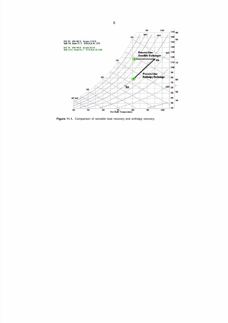
7/18/2019 Ventilation Guide
http://slidepdf.com/reader/full/ventilation-guide 199/223
6
Figure 11.1. Comparison of sensible heat recovery and enthalpy recovery.
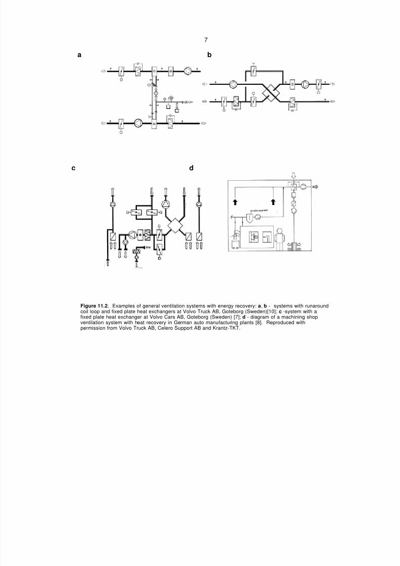
7/18/2019 Ventilation Guide
http://slidepdf.com/reader/full/ventilation-guide 200/223
7
a b
c d
Figure 11.2. Examples of general ventilation systems with energy recovery: a, b - systems with runaroundcoil loop and fixed plate heat exchangers at Volvo Truck AB, Goteborg (Sweden)[10]; c -system with afixed plate heat exchanger at Volvo Cars AB, Goteborg (Sweden) [7]; d - diagram of a machining shopventilation system with heat recovery in German auto manufacturing plants [8]. Reproduced withpermission from Volvo Truck AB, Celero Support AB and Krantz-TKT.

7/18/2019 Ventilation Guide
http://slidepdf.com/reader/full/ventilation-guide 201/223
12. SPECIAL REQUIREMENTS TO DUCT SELECTION AND DESIGN
12.1. General considerations.
Supply and exhaust air duct systems shall be designed to ensure:
• Design airflow rates;
• Low pressure drop;
• Minimum heating and cooling energy loss from air supplied with a temperature higher or
lower than room air temperature (e.g., duct insulation);
• Duct noise abatement;
• Prevention of air leakage and supply air contamination; and
• Coordination with other trades.
The designer shall carefully analyze each application and specify the duct materials, duct
construction and installation standards, and seal levels required. For duct systems conveying or
exhausting contaminated air, or installed in the contaminated environment, the designer shall
additionally specify the industrial duct class that most closely describes the intended use of the
system. Round ducts are preferred for industrial general supply and exhaust systems, pollution
control and dust collection systems.
For duct system construction requirements refer to either SMACNA “Round Industrial Duct
Construction Standards” [9], or SMACNA “HVAC Duct Construction standards - Metal and
Flexible” [9], VDl 3802 [11], or other relevant national standards, as required by the specifier. For
system design Information refer to ACGIH [1], ASHRAE [2,3] and ANSI/AIHA [4]. For duct
system fire protection requirements refer to NFPA [6.7].
The duct construction shall be selected and the system shall be designed with consideration of
the materials contaminating the transported air (their abrasiveness and concentration), and the
minimum air velocity for transporting these contaminants. Duct classes, minimum transporting air
velocities, and recommended static pressure loss in supply and exhaust duct systems are listed
in Table 12.1
The minimum transporting velocities are specified such as to minimize material accumulation in
the duct system (in the case of dry contaminants). Air control devices are to be avoided as much
as possible, as deposits can form at these points. In metal working fluids (MWF) collection
systems the transport air velocity can be lower than that recommended for transporting dry
contaminants. Increased travel time caused by slower velocity contributes to droplet
agglomeration, which results in extended filter life.
The ducts must be routinely maintained and cleaned (particularly when transporting flammable
materials, e.g., oil mist). Easily dismountable duct components, and maintenance and cleaning
openings shall be provided. In the case of liquid and condensable vapors, all horizontal ducts
shall be inclined and fitted with devices for trapping and draining the condensate. In the case of
vertical ducts, drainable collection points shall be provided at the bottom end of the duct. The
ducts shall be manufactured and installed to be sufficiently leak tight in order that the collection
efficiency is not impaired by leakage and so that condensing substances do not escape (VDI
2262 [10]).
Depending on the application, operating temperature, and type of air contaminant, different
materials are used in industrial duct construction. The most commonly used are: hot-rolled or
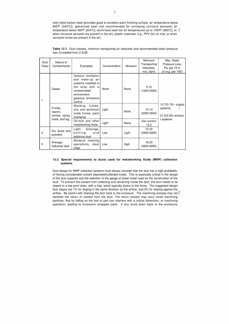
7/18/2019 Ventilation Guide
http://slidepdf.com/reader/full/ventilation-guide 202/223
2
cold rolled carbon steel (provides good to excellent paint finishing surface, air temperature below
650oF [343oC]), galvanized steel (not recommended for conveying corrosive aerosols) air
temperature below 400oF [204oC], aluminized steel (for air temperatures up to 1050oF [565oC], or
when corrosive aerosols are present in the air), plastic materials, e.g., PPV (for oil mist, or when
corrosive fumes are present in the air).
Table 12.1. Duct classes, minimum transporting air velocities and recommended static pressure
loss (Compiled from [1,8,9])
Duct
Class
Nature of
Contaminants Examples Concentration Abrasion
Minimum
Transporting
Velocities,
m/s, (fpm)
Max. Static
Pressure Loss,
Pa, per 10 m
(in.w.g. per 100’)
Gases
General ventilation
and make-up air
systems installed in
the shop with acontaminated
environment,
gaseous emissions
control
None None 5-10(1000-2000)
Welding fumes,
zinc and aluminum
oxide fumes, paint
overspray
LightNone
10-13
(2000-2500)
1
Fumes,
vapors,
smoke, spray,
mists, and fogOil-mist and other
metalworking fluidsLight None
See section
12.2
2 Dry dusts andpowders
Light shavings,
b u f f i n g a n d
polishing dust
Low Light
15-20
(2500-3000)
3Average
industrial dust
Abrasive cleaning
operations, steel
chips
Low High18-20
(3500-4000)
12.7(0.15)– supply
systems
21.2(0.25)–exhaus
t systems
12.2. Special requirements to ducts used for metalworking fluids (MWF) collection
systems.
Duct design for MWF collection systems must always consider that the duct has a high probability
of having considerable coolant deposited/collected inside. This is especially critical in the designof the duct supports and the selection of the gauge of sheet metal used for the construction of the
duct. To prevent the coolant from collecting and remaining inside the duct, the duct needs to be
sloped to a low point drain, with a trap, which typically drains to the flume. The suggested design
duct slopes are 1% for sloping in the same direction as the airflow, and 2% for sloping against the
airflow. Be careful with draining the duct back to the enclosure. The machining process may not
facilitate the return of coolant from the duct. The return coolant may carry small machining
particles, that by falling on the tool or part can interfere with a critical dimension, or machining
operation, leading to excessive scrapped parts. If any ducts drain back to the enclosure,
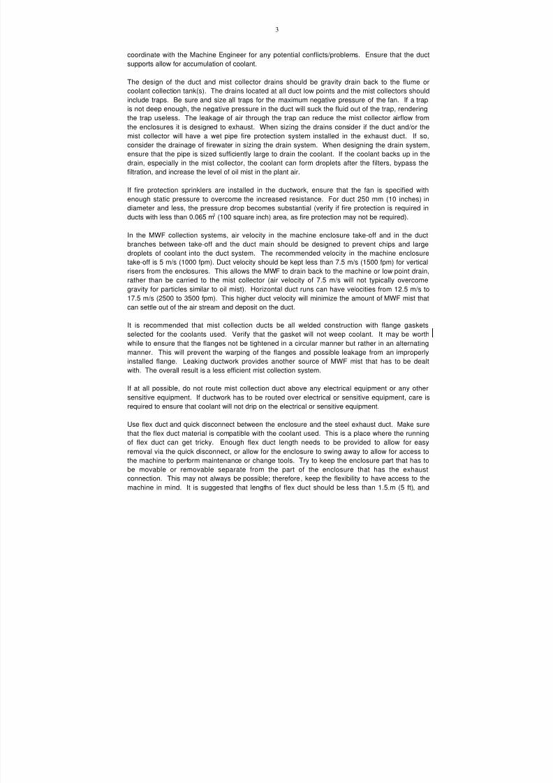
7/18/2019 Ventilation Guide
http://slidepdf.com/reader/full/ventilation-guide 203/223
3
coordinate with the Machine Engineer for any potential conflicts/problems. Ensure that the duct
supports allow for accumulation of coolant.
The design of the duct and mist collector drains should be gravity drain back to the flume or
coolant collection tank(s). The drains located at all duct low points and the mist collectors should
include traps. Be sure and size all traps for the maximum negative pressure of the fan. If a trap
is not deep enough, the negative pressure in the duct will suck the fluid out of the trap, rendering
the trap useless. The leakage of air through the trap can reduce the mist collector airflow from
the enclosures it is designed to exhaust. When sizing the drains consider if the duct and/or the
mist collector will have a wet pipe fire protection system installed in the exhaust duct. If so,
consider the drainage of firewater in sizing the drain system. When designing the drain system,
ensure that the pipe is sized sufficiently large to drain the coolant. If the coolant backs up in the
drain, especially in the mist collector, the coolant can form droplets after the filters, bypass the
filtration, and increase the level of oil mist in the plant air.
If fire protection sprinklers are installed in the ductwork, ensure that the fan is specified with
enough static pressure to overcome the increased resistance. For duct 250 mm (10 inches) in
diameter and less, the pressure drop becomes substantial (verify if fire protection is required inducts with less than 0.065 m2 (100 square inch) area, as fire protection may not be required).
In the MWF collection systems, air velocity in the machine enclosure take-off and in the duct
branches between take-off and the duct main should be designed to prevent chips and large
droplets of coolant into the duct system. The recommended velocity in the machine enclosure
take-off is 5 m/s (1000 fpm). Duct velocity should be kept less than 7.5 m/s (1500 fpm) for vertical
risers from the enclosures. This allows the MWF to drain back to the machine or low point drain,
rather than be carried to the mist collector (air velocity of 7.5 m/s will not typically overcome
gravity for particles similar to oil mist). Horizontal duct runs can have velocities from 12.5 m/s to
17.5 m/s (2500 to 3500 fpm). This higher duct velocity will minimize the amount of MWF mist that
can settle out of the air stream and deposit on the duct.
It is recommended that mist collection ducts be all welded construction with flange gaskets
selected for the coolants used. Verify that the gasket will not weep coolant. It may be worth
while to ensure that the flanges not be tightened in a circular manner but rather in an alternating
manner. This will prevent the warping of the flanges and possible leakage from an improperly
installed flange. Leaking ductwork provides another source of MWF mist that has to be dealt
with. The overall result is a less efficient mist collection system.
If at all possible, do not route mist collection duct above any electrical equipment or any other
sensitive equipment. If ductwork has to be routed over electrical or sensitive equipment, care is
required to ensure that coolant will not drip on the electrical or sensitive equipment.
Use flex duct and quick disconnect between the enclosure and the steel exhaust duct. Make surethat the flex duct material is compatible with the coolant used. This is a place where the running
of flex duct can get tricky. Enough flex duct length needs to be provided to allow for easy
removal via the quick disconnect, or allow for the enclosure to swing away to allow for access to
the machine to perform maintenance or change tools. Try to keep the enclosure part that has to
be movable or removable separate from the part of the enclosure that has the exhaust
connection. This may not always be possible; therefore, keep the flexibility to have access to the
machine in mind. It is suggested that lengths of flex duct should be less than 1.5.m (5 ft), and

7/18/2019 Ventilation Guide
http://slidepdf.com/reader/full/ventilation-guide 204/223
4
that flex duct not be used for horizontal runs. It is recommended that flex duct be installed
stretched out minimizing low points or traps for coolant. With flex duct not stretched taught
coolant could collect and shorten the life of the flex duct and/or seep through the flex duct
(especially if the compatibility of the flex duct and coolant is poor). Without flexibility,
maintenance of the machine is more difficult, and may not be performed or will be performed less
often, or the duct will be disconnected and left disconnected, which will lessen the effectiveness
of the enclosure. Work with the Tool Designer, the Enclosure Designer, and the Machine
Engineer to provide the flexibility needed, while not exceeding the design requirements of flex
duct.
When selecting flex duct, be aware of the temperature of the discharge air (some estimated
enclosure temperatures are 54oC (130oF). Abrasion resistance is a variable that needs to be
evaluated since some flex duct materials provide excellent abrasion resistance, and others
provide no abrasion resistance. Verify the coolants used, especially if synthetic or semi-synthetic
coolants are used. The coolant MSDS sheets provide a breakdown of the chemicals in the
coolant.
If sound attenuators are required, care is required to keep the sound attenuator from becoming oillogged.
Damper location can add a trap to collect oil mist. Care is required with the installation of
dampers. It is suggested that duct dampers be located in vertical sections of the exhaust duct.
Galvanized duct is cheaper than painted duct; but, the galvanized coating may chip off and it may
prematurely plug the filters in the mist collector. If the inside of the exhaust duct needs to be
painted, care needs to be exercised so that the paint will not chip and be transported to the mist
collector. For some painting applications, it is cheaper to use stainless steel rather than paint.
When coating is required evaluate the requirements of the coating and the cost of applying the
coating vs. the effect. It may be worthwhile to also evaluate installing stainless steel duct as a
lower total installed first cost, without the problem of chipping or corrosion
12.3. References
1. ACGIH. 1998. Industrial Ventilation, A Manual of Recommended Practice. 23rd Edition.
American Conference of Governmental Industrial Hygienists, Inc. Cincinnati, OH.
2. ASHRAE. 1999. ASHRAE Handbook. HVAC Applications. American Society of Heating,
Refrigerating and Air Conditioning Engineers, Inc. Atlanta, GA.
3. ASHRAE. 1997. ASHRAE Handbook. Fundamentals. American Society of Heating,
Refrigerating and Air Conditioning Engineers, Inc. Atlanta, GA.
4. ANSI/AIHA. 1991. Standard Z9.2-1979 (R1991). Fundamentals Governing the Design and
Operation of Local Exhaust Systems. American National Standards Institute. New York, NY.
5. NFPA. 1999. NFPA 90A – 99 Standard for the Installation of Air - Conditioning and
Ventilating Systems. National Fire Protection Association. Quincy, MA6. NFPA. 1999. NFPA 91-99 Exhaust Systems for Air Conveying of Vapors, Gases, Mists, and
Noncombustible Particulate Solids. National Fire Protection Association. Quincy, MA.
7. NFPA. 1998. NFPA 650-98 "Pneumatic Conveying Systems for Handling Combustible
materials". National Fire Protection Association. Quincy, MA..
8. SMACNA. 1999. Round Industrial Duct Construction Standards. Second Edition. Sheet
Metal and Air Conditioning Contractors National Association, Inc. Chattily, VA.

7/18/2019 Ventilation Guide
http://slidepdf.com/reader/full/ventilation-guide 205/223
5
9. SMACNA. 1995. HVAC Duct Construction Standards – Metal and Flexible. Second Edition.
Sheet Metal and Air Conditioning Contractors National Association, Inc. Chattily, VA.
10. VDI 2262. 1994. Workplace Air. Reduction of Exposure to Air Pollutants. Ventilation
Technical Measures. Part 3. VDI-Handbuch Reinhaultung. D_sseldorf.
11. VDI 3802. 1997. Raumlufttechnische Anlagen. Bauliche und technische Anforforderungen.
VDI-Handbuch Reinhaultung. D_sseldorf.

7/18/2019 Ventilation Guide
http://slidepdf.com/reader/full/ventilation-guide 206/223
13. METHODS OF BUILDING PROTECTION FROM WARM/COLD AIR DRAFTS THROUGH
GATES AND OTHER APERTURES.
Air curtains are local ventilation devices that reduce airflow through apertures in building
shells1
. Air curtains:• provide better thermal environments for workstations located close to doorways;
• reduce energy consumption of HVAC systems;
• support airflow and pressure management control in the building.
The following types of air curtains are typically used in heated or cooled industrial
shops:
• Shutter type – create a resistance to airflow through a door and thus reduce the
incoming airflow;
• Air curtains with a lobby; and
• Air lock.
Air curtains may be double-sided (Figure 13.1a) or single-sided (Figure 13.1b).
Supply air jets can be directed upward, downward or sideward (with vertical air supply
slots). Air curtains used in industrial buildings are often double sided because they deter
the airflow better. Upward projected air curtain are recommended when the gate width
is greater, than its height. They also provide better coverage of the lower area of the
door opening.
Air curtains can supply heated air, air at room temperature, or air with the outdoor
temperature.
Air curtains with heated air are recommended for doors smaller than 3.6m x 3.6m (12ft x
12 ft) and that are located in regions with design outdoor winter temperature of –15oC
(5oF) and lower.
Air curtains that supply unheated indoor air have application in spaces with a
• heat surplus;
• temperature stratification along the room height;
• acceptable low air temperature (less than 8oC, 46oF), near the door area, and
• buildings located in regions with a mild climate.
Combined air curtain (Figure 13.1.c) consists of two sequentially installed air curtains:(1) heated air curtain and (2) unheated air curtain. They are used
• In regions having a very cold climate;
• For doors larger, than 3.6m x 3.6m (12ft x 12 ft); and
• For spaces with several doors.
1 ASHRAE Handbook. HVAC Applications. 1999. American Society of Heating, Refrigerating and
Air-Conditioning Engineers. Atlanta, GA.

7/18/2019 Ventilation Guide
http://slidepdf.com/reader/full/ventilation-guide 207/223
2
Air curtains with a lobby. Their performance is based on transition of the supply jet
momentum into counter pressure, which prevents outdoor airflow into the shop (Figure
13.2.). Air is supplied in a direction opposite to that of the outdoor airflow or at a small
angle to it. The lobby can be located inside (Figure 13.3) or outside the building (Figure
13.2). Air curtain with a lobby manufactured from the corrugated iron walls that reducethe wind pressure on the gate is shown in Figure 13.2. Air can be supplied through a
slot-type air diffuser installed along the duct (Figure 13.2b), or through a row of small
size nozzles (Figure 13.2.c). Special measures should be considered to prevent
negative pressure in the building when the wind pressure is smaller than the design
value used to calculate the supply jet momentum.
A combined air curtain with a specially designed lobby is shown in Figure aperture. Air
curtains in the lobby supply untreated outdoor air, while air curtains inside the building
supply heated air (Figure 13.4).
Air lock. The building space is protected from the outdoor air by two sequentiallyinstalled gates with an enclosed space (“air lock”) between them (Figure 13.5). In some
“air lock” designs, air curtains are used to supply heated or unheated indoor air into the
“air lock” (Figure 13.6). There is only one gate open at a time to let a vehicle in or out
the building. After the vehicle enters the “air lock”, the first gate closes and the second
one opens.
To increase the traffic and to reduce energy loss, flexible doors with a fast
opening/closing time are used (Figure 13.7). These doors also allow reduced air leaks
through the gaps between the building and the door perimeter.
Also, reduction of energy loss can be achieved by using two settings for the door height(width) opening: regular automatic setting, and occasional manual setting allowing the
complete door opening.
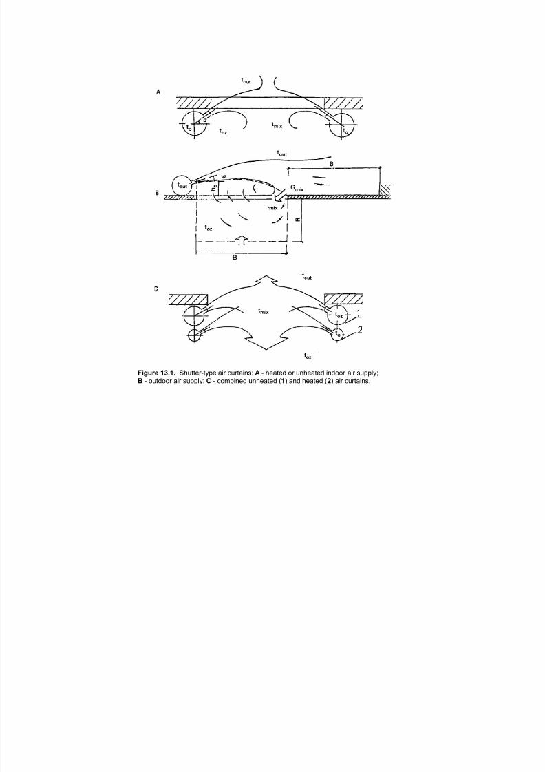
7/18/2019 Ventilation Guide
http://slidepdf.com/reader/full/ventilation-guide 208/223
1
2
Figure 13.1. Shutter-type air curtains: A - heated or unheated indoor air supply;
B - outdoor air supply; C - combined unheated (1) and heated (2) air curtains.
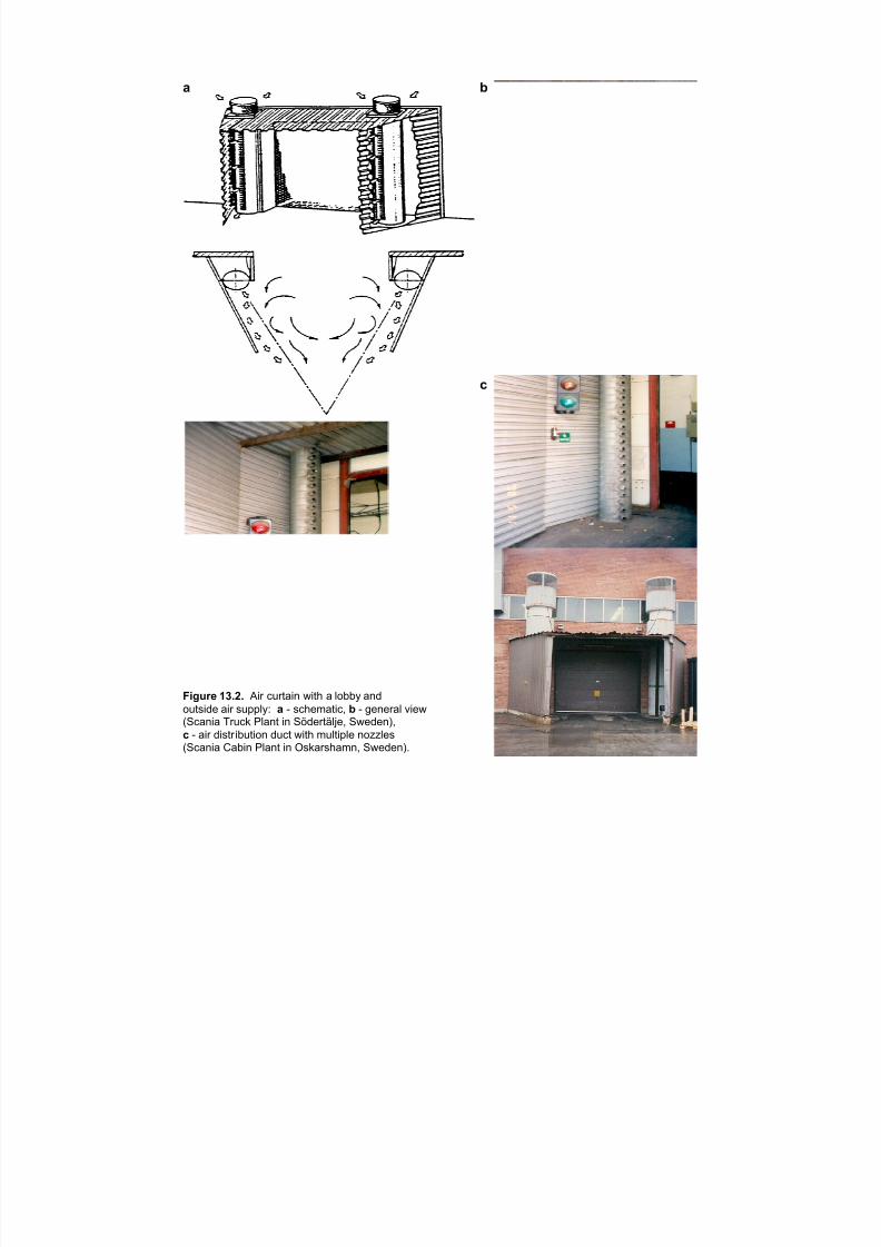
7/18/2019 Ventilation Guide
http://slidepdf.com/reader/full/ventilation-guide 209/223
a b
c
Figure 13.2. Air curtain with a lobby and
outside air supply: a - schematic, b - general view(Scania Truck Plant in Södertälje, Sweden),
c - air distribution duct with multiple nozzles(Scania Cabin Plant in Oskarshamn, Sweden).

7/18/2019 Ventilation Guide
http://slidepdf.com/reader/full/ventilation-guide 210/223
!"#$%& ()*)* "#$ %&$'(#) *#'+ '+, -.//0 -.%(',1 #)2#1, (' '+, 3(%+#)#)4 2+.56 7.$18,$9, :.,-);<,#- #) =,$3()0> ?,(',1 (#$ #2 2&55-#,1 '+$.&4+ ( 2-.' #) '+, @-..$>
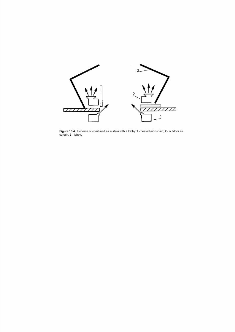
7/18/2019 Ventilation Guide
http://slidepdf.com/reader/full/ventilation-guide 211/223
1
2
3
Figure 13.4. Scheme of combined air curtain with a lobby: 1 - heated air curtain; 2 - outdoor air
curtain, 3 - lobby.
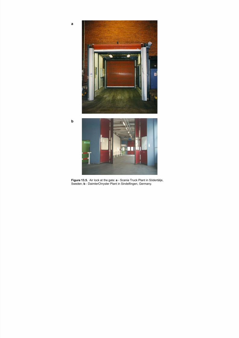
7/18/2019 Ventilation Guide
http://slidepdf.com/reader/full/ventilation-guide 212/223
a
b
Figure 13.5. Air lock at the gate: a - Scania Truck Plant in Södertälje,
Sweden; b - DaimlerChrysler Plant in Sindelfingen, Germany.
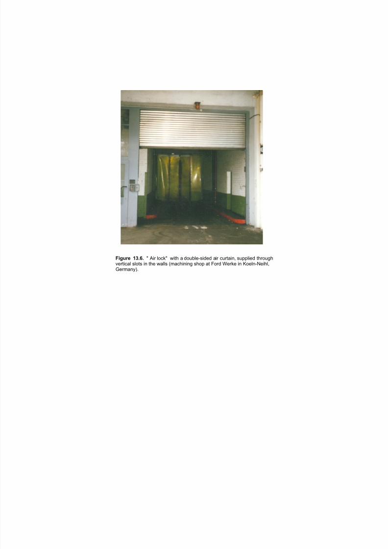
7/18/2019 Ventilation Guide
http://slidepdf.com/reader/full/ventilation-guide 213/223
Figure 13.6. " Air lock" with a double-sided air curtain, supplied throughvertical slots in the walls (machining shop at Ford Werke in Koeln-Neihl,Germany).
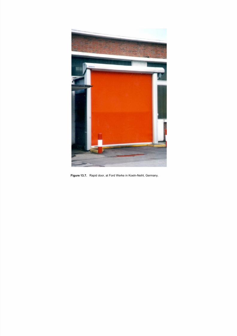
7/18/2019 Ventilation Guide
http://slidepdf.com/reader/full/ventilation-guide 214/223
Figure 13.7. Rapid door, at Ford Werke in Koeln-Neihl, Germany.
7/18/2019 Ventilation Guide
http://slidepdf.com/reader/full/ventilation-guide 215/223
!"# %&'(%%) *+) ,%--&'+%. ,)/0/.'+%.
!"#! +11231
!" $%&'("'"( )%"*'+,*'-" &.&*%/& 0-1 *2% ,3*-/-*')% '"$3&*1.4 *5- -3*$--1 ,'1 6-++3*'-" '&&3%& "%%$ *- 7%
,$$1%&&%$8 9:; *2% 6-*%"*',+ 0-1 <-"*,/'","*& '" *2% %=2,3&* ,'1 -0 *2% )%"*'+,*'-" &.&*%/ *- <,3&% ,$)%1&%%00%<*& '" *2% &311-3"$'"( %")'1-"/%"*> ,"$ 9?; *2% 6-*%"*',+ 0-1 *2-&% <-"*,/'","*& -1 -*2%1 <-"*,/'","*&
01-/ "%,17. %/'&&'-" &-31<%& *- %"*%1 *2% )%"*'+,*'-" &.&*%/ ,* *2% 01%&2 ,'1 '"*,@%&A
,4567 189:1# B2% 61-<%&& %/'&&'-"& -0 (1%,*%&* <-"<%1" ,1% %),6-1,*')% +-&&%& -0 )-+,*'+% -1(,"'<
<-/6-3"$& 9CDEF&; 01-/ &61,. 7--*2&4 <31'"( -)%"& ,"$ 5,&*% 5,*%1 *1%,*/%"* 6+,"*&A B2%&% CDEF&
2,)% , 2'&*-1. -0 <,3&'"( &'("'0'<,"* -$-31 '/6,<*& '" &311-3"$'"( "%'(27-312--$& ,"$ 1%G'"(%&*'-" '"*-
73'+$'"( '"*,@%&A E+%,1<-,* -6%1,*'-"& ,1% -0 6,1*'<3+,1 <-"<%1"4 &'"<% <+%,1<-,* 0-1/3+,*'-"& *%"$ *-
<-"*,'" &'("'0'<,"* ,/-3"*& -0 ,<%*,*%& *2,* 2,)% 6,1*'<3+,1+. &*1-"( -$-31&A HG73*.+ ,<%*,*% 2,& -"% -0
*2% +-5%&* -$-31 *21%&2-+$& ,/-"( *2% &-+)%"*& 5'$%+. 3&%$ '" 6,'"* 0-1/3+,*'-"&A I-/% 6,'"* &2-6& 5'++3&% *2%1/,+ -='$,*'-" 9'A%A4 '"<'"%1,*'-"; ,& , /%,"& -0 <-"*1-++'"( &-/% -0 *2% CDE %/'&&'-"& 01-/
<--+'"( *3""%+& ,"$ -)%"&4 '" 52'<2 <,&% *2% 1%&3+*'"( %/'&&'-"& -0 <,17-" /-"-='$% 9ED; ,"$ -='$%& -0
"'*1-(%" 9HD ; ,1% 6-*%"*',+ <-"<%1"&A I'/'+,1 %/'&&'-"& /3&* 7% <-"&'$%1%$ 01-/ <31'"( -)%"&A J"-*2%1 K
61-7+%/ 52'<2 <," -<<31 01-/ 6,'"* 7--*2 %=2,3&* &*,<@& '& *2% <,11. -3* -0 6,'"* 6,1*'<3+,*% 52'<2 <,"
<,3&% $,/,(% *- 61-6%1*. -" &'*% ,"$ -00 &'*%A
;9<= 189:1# B2% %/'&&'-" -0 (1%,*%&* <-"<%1" '& *2% 6,1*'<3+,*% /,**%1 '" 5%+$'"( 03/%&A B2'&
6,1*'<3+,*% /,**%1 <," '"<+3$% , ),1'%*. -0 *1,<% /%*,+&4 $%6%"$'"( -" *2% *.6% -0 5%+$'"( *2,* *,@%& 6+,<%A
>4?8563 189:1 46< @9AB56B 9:3A475961# B2% %/'&&'-"& -0 (1%,*%&* <-"<%1" ,1% *2% /'&*& ,"$ 03/%&
,&&-<',*%$ 5'*2 <3**'"( -'+&4 52'<2 <," +%,$ *- ,$)%1&% -$-31 '/6,<*& '" &311-3"$'"( "%'(27-312--$&A
L,<2'"% &2-6& ,"$ 7-$. &2-6& <," ,+&- 61-$3<% %=*%"&')% 6,1*'<3+,*% /,**%1 '" <-""%<*'-" 5'*2 <3**'"(
,"$ (1'"$'"( -6%1,*'-"&A
*113CDE= :E4671# B2% %/'&&'-"& -0 <-"<%1" '"<+3$% %=2,3&* %/'&&'-"& ,&&-<',*%$ 5'*2 %"('"% &*,1*G36
,"$ *%&* &*,*'-"&A D00G(,&&'"( -0 &-+)%"*& '" ,$2%&')%& 3&%$ *- &%,+ *2% 5'"$&2'%+$ *- *2% 01,/% ,"$ *-
,**,<2%$ $--1 &%,+& '& ,+&- , 6-*%"*',+ <-"<%1"A
%783A 45A :9EE27596 192A?31# J *.6'<,+ ,3*-/-*')% 6+,"* 5'++ ,+&- 2,)% 3*'+'*. 7-'+%1&4 &6,<% 2%,*%1& ,"$
<--+'"( *-5%1&A B2% %=2,3&* &*,<@& -0 *2%&% &.&*%/& /3&* 7% +-<,*%$ ,"$ $%&'("%$ &- ,& *- /'"'/'M% *2%
6-*%"*',+ 0-1 *2% %=2,3&* (,&%& *- %"*%1 *2% 6+,"* )%"*'+,*'-" &.&*%/A !0 *2% 7-'+%1& ,"$ &6,<% 2%,*%1& ,1%
0'1%$ 5'*2 ",*31,+ (,&4 *2%" ED ,"$ HD ,1% *2% <-"*,/'","*& -0 <-"<%1" '" *2% <-/73&*'-" (,&%&A N2%"K
*2%&% 3"'*& ,1% 0'1%$ 5'*2 03%+ -'+4 %/'&&'-"& -0 &3+6231 $'-='$% 9ID ; ,"$ 6,1*'<3+,*% /,**%1 /3&*?

7/18/2019 Ventilation Guide
http://slidepdf.com/reader/full/ventilation-guide 216/223
!
,+&- 7% *,@%" '"*- <-"&'$%1,*'-"A
J"-*2%1 '/6-1*,"* &-31<% -0 ,'1 6-++3*'-" ,* +,1(% ,3*-/-*')% 0,<'+'*'%& '& %"*1,'"/%"* -0 $'%&%+ 03/%& 01-/
*1,"&6-1* *13<@& '"*- *2% )%"*'+,*'-" ,'1 *21-3(2 *2% 01%&2 ,'1 '"*,@%&A O,1*'<3+,*% /,**%1 ,"$ HD ,"$ '"K
$'%&%+ 03/%& ,1% &'("'0'<,"* 6-*%"*',+ -<<36,*'-",+ 2%,+*2 <-"<%1"&A !" ,$$'*'-"4 -$-31& ,&&-<',*%$ 5'*2
$'%&%+ 03/%& ,1% , <-//-" <,3&% -0 <-/6+,'"*& '" "%'(27-312--$& &311-3"$'"( *13<@'"( -6%1,*'-"&A
!"#F G746<4A<1 46< HA573A54
!"$3&*1',+ ,'1 6-++3*'-" '& (%"%1,++. 1%(3+,*%$ '" *21%% 5,.&8
P %/'&&'-" +'/'*& 7,&%$ -" ,),'+,7+% <-"*1-+ *%<2"-+-(.>
P -<<36,*'-",+ %=6-&31% +'/'*&4 'A%A4 6-++3*,"* <-"<%"*1,*'-" +'/'*& *2,* ,1% ,66+'<,7+% *- -"G&'*%
+-<,*'-"& 52%1% 5-1@%1& <," 7% %=6-&%$ *- *2% 6-++3*,"*&>
P ,/7'%"* ,'1 &*,"$,1$&4 'A%A4 6-++3*,"* <-"<%"*1,*'-" +'/'*& *2,* ,1% ,66+'<,7+% ,* -00G&'*% 1%&'$%"<%&
,"$ -*2%1 &%"&'*')% +-<,*'-"&>
/C511596 E5C571# B2% QI ROJ '& '" *2% 61-<%&& -0 %&*,7+'&2'"( ",*'-",+ %/'&&'-" &*,"$,1$& 0-1
2,M,1$-3& ,'1 6-++3*,"*& 9HRISJO&; *2,* ,1% &<2%$3+%$ *- ,00%<* *2% ,3*-/-*')% &310,<% <-,*'"( '"$3&*1.
7. *2% .%,1 ?TTTA !"$')'$3,+ &*,*%&4 &3<2 ,&
L'<2'(,"4 ,+1%,$. 2,)% %/'&&'-" +'/'* 1%U3'1%/%"*& 0-1 ),1'-3& 6-++3*,"*& *2,* ,1% 1%+%),"* *- *2%
,3*-/-*')% '"$3&*1.A B2% V31%,3 -0 H,*'-",+ J00,'1& '" N,&2'"(*-"4 WE4 637+'&2%& , ),+3,7+% 1%0%1%"<%
0-1 '"0-1/,*'-" -" 0%$%1,+ ,"$ &*,*% ,'1 6-++3*'-" 1%(3+,*'-"& '" *2% QI4 '" 52'<2 031*2%1 $%*,'+& -" %/'&&'-"
1%U3'1%/%"*& <," 7% 0-3"$ XYZA
%??2:475964E 3I:912A3 E5C571# L-&* [31'&$'<*'-" *21-3(2-3* *2% 5-1+$ 2,)% +,7-31 1%(3+,*'-"& *2,*
'"<+3$% -<<36,*'-",+ %=6-&31% +'/'*&A !" *2% QI4 0-1 %=,/6+%4 *2% H,*'-",+ !"&*'*3*% 0-1 D<<36,*'-",+
I,0%*. ,"$ S%,+*2 9H!DIS; '& 1%&6-"&'7+% 0-1 1%&%,1<2'"( ,"$ 1%<-//%"$'"( "%5 2%,+*2 ,"$ &,0%*.
&*,"$,1$&4 52'<2 ,1% *2%" 63* '"*- *2% 1%(3+,*'-"& 7. *2% D<<36,*'-",+ I,0%*. ,"$ S%,+*2 J$/'"'&*1,*'-"
9DISJ;A H!DIS 1%(3+,1+. 637+'&2%& , *,73+,*'-" -0 '*& 1%<-//%"$%$ %=6-&31% +'/'*&A
B2% J/%1'<," E-"0%1%"<% -0 \-)%1"/%"*,+ !"$3&*1',+ S.('%"'&*& 9JE\!S;4 $%)%+-6& B21%&2-+$ ]'/'*
C,+3%& 9B]CF&; 0-1 , 5'$% 1,"(% -0 ,'1 6-++3*,"*&A B]CF& 1%61%&%"* *21%&2-+$ <-"<%"*1,*'-"& *2,* /-&*
5-1@%1& <," 7% %=6-&%$ *- -" , $,.G*-G$,. 7,&'& 5'*2-3* ,". ,$)%1&% 2%,+*2 %00%<*A X:ZA B2% JE\!S
B]CF& ,1% 5'$%+. 3&%$ *21-3(2-3* *2% 5-1+$ ,& '"$3&*1. &*,"$,1$& 0-1 -<<36,*'-",+ %=6-&31%A

7/18/2019 Ventilation Guide
http://slidepdf.com/reader/full/ventilation-guide 217/223
"
*CD5367 45A 1746<4A<1# L-&* [31'&$'<*'-"& *21-3(2-3* *2% 5-1+$ 2,)% ,* +%,&* &-/% ,/7'%"* ,'1 &*,"$,1$&
,"$^-1 -7[%<*')%& *2,* ,66+. *- ,3*-/-*')% 0,<'+'*'%&A E-<21,"4 %* ,+A X_Z 61-)'$%$ , &3//,1. -0 &%+%<*%$ ,'1
6-++3*,"* &*,"$,1$& '" *5%"*.G*21%% <-3"*1'%& 52'<24 ,+*2-3(2 -3*G-0G$,*% 0-1 &-/% <-3"*1'%&4 '& &*'++ ,
3&%03+ 1%0%1%"<%A
B2% QI 2,& H,*'-",+ J/7'%"* J'1 `3,+'*. I*,"$,1$& 0-1 &'= @%. 6-++3*,"*&8 ED4 ID 4 "'*1-(%" $'-='$%?
9HD ;4 +%,$ 9O7;4 -M-"% 9D ; ,"$ '"2,+,7+% 6,1*'<3+,*% /,**%1 9OLG:T;A B2%&% 6-++3*,"*& ,1% @"-5" ,& *2%? Y
<1'*%1', 6-++3*,"*&A !" ,$$'*'-" *- *2% ",*'-",+ &*,"$,1$&4 &-/% &*,*%& &3<2 ,& H%5 a-1@ I*,*% 2,)%
,/7'%"* ,'1 &*,"$,1$& 0-1 ),1'-3& -*2%1 6-++3*,"*&4 '"<+3$'"( &-/% -0 *2% &-+)%"*& 3&%$ '" ,3*-/-*')% 6,'"*
0-1/3+,*'-"& ,"$ ,$2%&')%&A
E,",$, 2,& ",*'-",+ ,/7'%"* ,'1 U3,+'*. -7[%<*')%& 0-1 ED4 ID 4 HD 4 D ,"$ &3&6%"$%$ 6,1*'<3+,*% /,**%1 ? ? Y
XbZA B2% -7[%<*')%& ,1% "-* %"0-1<%,7+% &*,"$,1$&4 73* ,1% 3&%$ '" %&*,7+'&2'"( ,'1 U3,+'*. 6-+'<'%& '"
E,",$,A !" ,$$'*'-" *- *2% 0%$%1,+ ,'1 U3,+'*. -7[%<*')%&4 /,". -0 *2% 61-)'"<%& 2,)% *2%'1 -5" &*,"$,1$&
,"$^-1 <1'*%1', 0-1 ,/7'%"* ,'1 U3,+'*.A B2% 61-)'"<% -0 D"*,1'-4 0-1 %=,/6+%4 2,& , <-/6+'<,*%$ &%* -0
,/7'%"* ,'1 &*,"$,1$&4 <1'*%1',4 ,"$ '"*%1'/ &*,"$,1$& *2,* ,66+. *- ED4 ID 4 HD 4 D 4 6,1*'<3+,*% /,**%14? ? Y
&%)%1,+ *1,<% /%*,+& *2,* <," 7% 0-3"$ '" 6,1*'<3+,*% /,**%1 ,"$ , ),1'%*. -0 CDEF&AXcZ
J/7'%"* ,'1 &*,"$,1$& ,1% '" *2% 0-1/ -0 , *21%&2-+$ <-"<%"*1,*'-" ,)%1,(%$ -)%1 , 6%1'-$ -0 :G2-314 dG
2-31&4 ?bG2-31&4 :G.%,1 ,"$ -1 -*2%1 ,)%1,('"( *'/%4 $%6%"$'"( -" *2% 6-++3*,"* ,"$ *2% [31'&$'<*'-"A !" ,
*.6'<,+ [31'&$'<*'-"4 *2% ,/7'%"* ,'1 &*,"$,1$& ,66+. *- *2% 6-++3*,"* +%)%+ <-"*1'73*%$ 7. ,++ &-31<%& ,* *2%
0,<'+'*. 7%'"( '")%&*'(,*%$4 '" <-/7'",*'-" 5'*2 *2% <-"*1'73*'-" 01-/ ,". -00G&'*% &-31<%& -0 *2% &,/%
6-++3*,"*A B2% <-"*1'73*'-" 01-/ -00G&'*% &-31<%& '& @"-5" ,& *2% 7,<@(1-3"$ 6-++3*,"* +%)%+A
!"#J (315B656B 79 >337 783 G746<4A<1
!* '& "%<%&&,1. *- %&*'/,*% 2-5 /3<2 -0 %,<2 6-++3*,"* %/'**%$ 01-/ %=2,3&* )%"*& ,"$ &*,<@& ,* , 0,<'+'*.
5'++ 1%,<2 &%"&'*')% -00G&'*% +-<,*'-"& ,"$ *2% 0,<'+'*.F& -5" 01%&2 ,'1 '"*,@%&A B2'& '& $-"% 0-1 , 1,"(% -0
&*,<@ $%&'("& ,"$ *2% 1%&3+*& ,1% <-/6,1%$ *- *2% ,66+'<,7+% -<<36,*'-",+ %=6-&31% +'/'*& ,"$ ,/7'%"* ,'1
&*,"$,1$&4 3"*'+ , $%&'(" '& , ,<2'%)%$ *2,* /%%*& *2% &*,"$,1$&A !" *2% <,&% -0 *2% ,/7'%"* ,'1 &*,"$,1$&4
*2% 7,<@(1-3"$ +%)%+ -0 %,<2 6-++3*,"* /3&* ,+&- 7% <-"&'$%1%$ '" *2'& ,",+.&'&A
B2% ,",+.&'& (%"%1,++. 0-++-5& , *21%%G&*%6 61-<%&&8
P %&*'/,*'-" -0 *2% 6-++3*,"* %/'&&'-" 1,*%& 0-1 *2% -"G&'*% &-31<%&>
P $'&6%1&'-" /-$%++'"( *- %&*'/,*% *2% 6-++3*,"* <-"<%"*1,*'-"& *2,* 5'++ -<<31 ,* &%"&'*')% -00G&'*%
+-<,*'-"& ,"$ ,* *2% 0,<'+'*.F& -5" 01%&2 ,'1 '"*,@%&>
P $%*%1/'",*'-" -0 7,<@(1-3"$ 6-++3*,"* +%)%+& 01-/ 2'&*-1'<,+ ,/7'%"* ,'1 /-"'*-1'"( $,*,A

7/18/2019 Ventilation Guide
http://slidepdf.com/reader/full/ventilation-guide 218/223
#
K5B2A3 !"#F# N'"$ &6%%$ 01%U3%"<. $,*,K5B2A3 !"#!# O+3/% 1'&% ,& , 03"<*'-" -0 5'"$&6%%$ ,"$ %='* )%+-<'*.
B2% %&*'/,*'-" -0 %/'&&'-" 1,*%& ,"$ *2% $'&6%1&'-" /-$%++'"( ,1% $'&<3&&%$ 031*2%1 '" &37&%U3%"*
&%<*'-"& -0 *2'& <2,6*%1A B2% 0-++-5'"( 6,1,(1,62& 61-)'$% &-/% (%"%1,+ (3'$,"<% *- ,&&'&* $%&'("%1& '"
/%%*'"( *2% &*,"$,1$&A
/I57 L3E9?57=# !" *2% <,&% -0 ,"$ %=2,3&* &*1%,/ <,11.'"( 2'(2+. -$-1-3& -1 *-='< 03/%&4 &3<2 ,& 6,'"*
&-+)%"*& -1 5%+$'"( 03/%&4 '* '& (%"%1,++. 7%&* *- $'&<2,1(% *2% %=2,3&* &*1%,/ )%1*'<,++. ,* , 1%+,*')%+. 2'(2
%='* )%+-<'*.A B2% 2'(2%1 *2% %='* )%+-<'*.4 *2% 2'(2%1 *2% 5'"$ &6%%$ "%%$%$ *- 7%"$ -)%1 *2% %=2,3&*
6+3/%A B2% 5'"$ &6%%$4 Q4 "%%$%$ *- 03++. 7%"$ -)%1 *2% 6+3/% '& ,7-3* ?^Y -0 *2% %='* )%+-<'*.4 N 9&%%
e'(31% :bA:;A N2%" *2% %='* )%+-<'*. '& 2'(24 *2% 61-7,7'+'*. -0 -<<311%"<% -0 &3<2 , 5'"$ &6%%$ '& +-5A e-1
/-&* +-<,*'-"&4 ," %='* )%+-<'*. -0 ,7-3* YTTT 06/ '& -6*'/,+ 0-1 /'"'/'M'"( *2% 61-7,7'+'*. -0 03++ 7%"$G-)%1
9&%% e'(31% :bA?;A
G74?M N35B87# I2-1* &*,<@& ,"$ 0+3&2 1--0 )%"*& ,1% (%"%1,++. *- 7% ,)-'$%$ 0-1 -$-1-3& -1 *-='< %=2,3&*
&*1%,/&A B2% %/'&&'-"& 01-/ &2-1* &*,<@& ,"$ )%"*& ,1% &3&<%6*'7+% *- $-5"5,1$ $%0+%<*'-" '" *2% +%% -0
*2% 6+,"* 73'+$'"(&4 52'<2 <," +%,$ *- &'("'0'<,"* '/6,<*& ,* *2% 6+,"*F& -5" 01%&2 ,'1 '"*,@%& ,"$ "%,17.
&%"&'*')% +-<,*'-"& '" *2% &311-3"$'"( ,1%,A B2'& 62%"-/%"-" '& @"-5" ,& 73'+$'"( $-5"5,&2 9e'(31%
:bAY;A B2% 6-*%"*',+ 0-1 $-5"5,&2 $%<1%,&%& 5'*2 '"<1%,&'"( &*,<@ 2%'(2*4 3"*'+ , 2%'(2* '& 1%,<2%$ ,*
52'<2 $-5"5,&2 "- +-"(%1 -<<31&A e31*2%1 '"<1%,&%& '" &*,<@ 2%'(2* -0*%" 61-)'$% 1%+,*')%+. +'**+%
,$$'*'-",+ 1%$3<*'-" '" 6-++3*,"* <-"<%"*1,*'-"&A
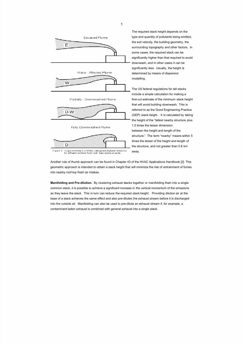
7/18/2019 Ventilation Guide
http://slidepdf.com/reader/full/ventilation-guide 219/223
$
B2% 1%U3'1%$ &*,<@ 2%'(2* $%6%"$& -" *2%
*.6% ,"$ U3,"*'*. -0 6-++3*,"*& 7%'"( %/'**%$4
*2% %='* )%+-<'*.4 *2% 73'+$'"( (%-/%*1.4 *2%
&311-3"$'"( *-6-(1,62. ,"$ -*2%1 0,<*-1&A !"
&-/% <,&%&4 *2% 1%U3'1%$ &*,<@ <," 7%
&'("'0'<,"*+. 2'(2%1 *2," *2,* 1%U3'1%$ *- ,)-'$
$-5"5,&24 ,"$ '" -*2%1 <,&%& '* <," 7%
&'("'0'<,"*+. +%&&A Q&3,++.4 *2% 2%'(2* '&
$%*%1/'"%$ 7. /%,"& -0 $'&6%1&'-"
/-$%++'"(A
B2% QI 0%$%1,+ 1%(3+,*'-"& 0-1 *,++ &*,<@&
'"<+3$% , &'/6+% <,+<3+,*'-" 0-1 /,@'"( ,
0'1&*G<3* %&*'/,*% -0 *2% /'"'/3/ &*,<@ 2%'(2*
*2,* 5'++ ,)-'$ 73'+$'"( $-5"5,&2A B2'& '&
1%0%11%$ *- ,& *2% \--$ R"('"%%1'"( O1,<*'<%
9\RO; &*,<@ 2%'(2*A !* '& <,+<3+,*%$ 7. *,@'"(
*2% 2%'(2* -0 *2% f*,++%&* "%,17. &*13<*31% 6+3&
:A_ *'/%& *2% +%&&%1 $'/%"&'-"
7%*5%%" *2% 2%'(2* ,"$ +%"(*2 -0 *2%
&*13<*31%Ag B2% *%1/ f"%,17.g /%,"& 5'*2'" _
*'/%& *2% +%&&%1 -0 *2% 2%'(2* ,"$ +%"(*2 -0
*2% &*13<*31%4 ,"$ "-* (1%,*%1 *2," TAd @/
,5,.A
J"-*2%1 13+% -0 *23/7 ,661-,<2 <," 7% 0-3"$ '" E2,6*%1 bY -0 *2% SCJE J66+'<,*'-"& S,"$7--@ X?Z B2'&
(%-/%*1'< ,661-,<2 '& '"*%"$%$ *- -7*,'" , &*,<@ 2%'(2* *2,* 5'++ /'"'/'M% *2% 1'&@ -0 %"*1,'"/%"* -0 03/%&
'"*- "%,17. 1--0G*-6 01%&2 ,'1 '"*,@%&A
>465@9E<56B 46< ,A3O<5E27596# V. <+3&*%1'"( %=2,3&* &*,<@& *-(%*2%1 -1 /,"'0-+$'"( *2%/ '"*- , &'"(+%
<-//-" &*,<@4 '* '& 6-&&'7+% *- ,<2'%)% , &'("'0'<,"* '"<1%,&% '" *2% )%1*'<,+ /-/%"*3/ -0 *2% %/'&&'-"&
,& *2%. +%,)% *2% &*,<@A B2'& '" *31" <," 1%$3<% *2% 1%U3'1%$ &*,<@ 2%'(2*A O1-)'$'"( $'+3*'-" ,'1 ,* *2%
7,&% -0 , &*,<@ ,<2'%)%& *2% &,/% %00%<* ,"$ ,+&- 61%G$'+3*%& *2% %=2,3&* &*1%,/ 7%0-1% '* '& $'&<2,1(%$
'"*- *2% -3*&'$% ,'1A L,"'0-+$'"( <," ,+&- 7% 3&%$ *- 61%G$'+3*% ," %=2,3&* &*1%,/ '04 0-1 %=,/6+%4 ,
<-"*,/'","*G+,$%" %=2,3&* '& <-/7'"%$ 5'*2 (%"%1,+ %=2,3&* '"*- , &'"(+% &*,<@A
7/18/2019 Ventilation Guide
http://slidepdf.com/reader/full/ventilation-guide 220/223
%
G74?M 46< +674M3 E9?47596# !* '& $%&'1,7+% 0-1 &*,<@& %/'**'"( -$-1-3& -1 *-='< (,&%& *- 7% +-<,*%$
$-5"5'"$ -0 "%,17. 01%&2G,'1 '"*,@%& 3"$%1 *2% 61%),'+'"( 5'"$ $'1%<*'-"& 0-1 *2% &'*%A N'"$ <+'/,*% $,*,
"%%$ *- 7% <-"&3+*%$ 0-1 *2'& 6316-&%A B2%&% $,*, <," 7% -7*,'"%$ 01-/ 637+'&2%$ <+'/,*% ,*+,&%&4 52%1%
,),'+,7+%4 ,"$ 01-/ ",*'-",+ /%*%-1-+-('<,+ &%1)'<%&A I3'*,7+% $,*, <," 7% -7*,'"%$ -" EWGhDL 0-1
+-<,*'-"& *21-3(2-3* *2% 5-1+$ 01-/ *2% H,*'-",+ E+'/,*'< W,*, E%"*1% '" J&2%)'++%4 H-1*2 E,1-+'",4 QIJA
!* '& ,+&- 2%+603+ *- ,)-'$ , $'1%<* +'"%G-0G&'*% 7%*5%%" 01%&2 ,'1 '"*,@%& ,"$ &*,<@& %/'**'"( -$-1-3& -1 *-='<
&37&*,"<%&4 52%1% 6-&&'7+%A !"*,@% +-<,*'-"& -" *2% &'$% -0 73'+$'"( -1 ,* *2% 7,&% -0 , 73'+$'"( ,1%
3&3,++. 7%**%1 *2," 1--0G*-6 +-<,*'-"&A
!"#J /175C4756B /C511596 )4731
W%*%1/'"'"( *2% ,66+'<,7+% <-"*,/'","*& ,"$ %&*'/,*'"( *2%'1 %/'&&'-" 1,*%& ,1% *2% 0'1&* &*%6& '"
$%&'("'"( %=2,3&* )%"*& *- ,)-'$ -3*&'$% ,'1 U3,+'*. 61-7+%/&A D"% -1 /-1% -0 *2% 0-++-5'"( /%*2-$& ,1%
*.6'<,++. 3&%$8
P $'1%<* /%,&31%/%"* -0 *2% %/'&&'-"& 3&'"( ,<<%6*%$ &*,<@ &,/6+'"( *%<2"'U3%& 52'<2 '& ,+5,.&
*2% 61%0%11%$ ,661-,<2>
P 637+'&2%$ %/'&&'-" 0,<*-1&>
P %"('"%%1'"( %&*'/,*%& 7,&%$ -" /,&& 7,+,"<% <,+<3+,*'-"& -1 -*2%1 &3'*,7+% /%*2-$A
B2% QI ROJ 637+'&2%& ," %=*%"&')% <-/6'+,*'-" -0 ,'1 6-++3*,"* %/'&&'-" 0,<*-1& *2,* '"<+3$%& $,*, 0-1
7-'+%1& ,"$ -*2%1 <-/73&*'-" &-31<%& XiZ4 ,"$ ,+&- '"<+3$%& %/'&&'-" $,*, 0-1 ),1'-3& 0-1/& -0 %+%<*1'<
,1<G5%+$'"(A B2'& 637+'<,*'-" $-%& "-* '"<+3$% %/'&&'-" $,*, 0-1 CDE %/'&&'-"& 01-/ 6,'"* &2-6&4 -1 0-1
-'+ /'&*& 01-/ /,<2'"% &2-6&A
N2%1% -$-31& ,1% , <-"<%1"4 ,& '& *2% <,&% 0-1 6,'"* &-+)%"*& ,"$ <3**'"( -'+ 03/%&4 '* '& 2'(2+. $%&'1,7+%
*- /%,&31% *2% 1%+,*')% -$-31 &*1%"(*2 -0 *2% %/'&&'-"&A O37+'&2%$ %/'&&'-" 0,<*-1& ,1% "-* 1%,$'+.
,),'+,7+%A !" *2% <,&% -0 6,'"* &2-6 -$-31&4 *2% /,("'*3$% -0 %/'**%$ -$-31& $%6%"$& -" /,". &6%<'0'<
0,<*-1&4 &3<2 ,& *2% *.6%& ,"$ U3,"*'*'%& -0 &-+)%"*& 3&%$ '" *2% 6,'"* 0-1/3+,*'-"&4 *2% 6,'"* 3&,(% 1,*%&4
*2% $%&'(" ,"$ -6%1,*'-" -0 *2% &61,. &.&*%/& ,"$ *2% $%&'(" -0 *2% 6,'"* 7--*2 )%"*'+,*'-"A
L%,&31%/%"* -0 -$-31 %/'&&'-"& <," 7% $-"% 7. *,@'"( &,/6+%& -0 *2% 03/%& *- ," -$-31 +,7 0-1 -$-31G
6,"%+ *%&*'"(A B2% 6%1<%6*'-" -0 -$-31 ),1'%& &'("'0'<,"*+. 01-/ -"% 6%1&-" *- ,"-*2%1A B2%1%0-1%4 '* '&
$%&'1,7+% *- <2,1,<*%1'M% -$-31& &*,*'&*'<,++.4 7,&%$ -" -7&%1),*'-"& 7. , 1,"$-/ &,/6+% -0 *2% (%"%1,+
6-63+,*'-"A D$-31 6,"%+ *%&*& 3&'"( , $.",/'< -+0,<*-/%*%1 2,)% 7%%" $%)%+-6%$ 0-1 *2'& 6316-&%A
7/18/2019 Ventilation Guide
http://slidepdf.com/reader/full/ventilation-guide 221/223
&
B2% 23/," "-&% '& )%1. 1%&6-"&')% *- -$-31& ,"$ <," $%*%<* *2%/ ,0*%1 -"+. , )%1. 71'%0 %=6-&31%A
B2%1%0-1%4 '* '& )%1. '/6-1*,"* *- <-"&'$%1 &2-1*G*%1/ -$-31 6%,@& *2,* 1%&3+* 01-/ 0+3<*3,*'"( 61-<%&&
%/'&&'-"& ,"$ 01-/ *3173+%"* 0+3<*3,*'-"& '" *2% -3*&'$% ,'1A I'"<% -$-31 6,"%+ *%&* /%*2-$& ,"$ &*,"$,1$
$'&6%1&'-" /-$%+& $- "-* $'1%<*+. ,<<-3"* 0-1 &2-1*G*%1/ 6%,@&4 ,661-='/,*% 0,<*-1& /3&* 7% 3&%$ *-
<-11%<* 61%$'<*'-"& 7,&%$ -" *2%&% /%*2-$&A e,<*-1& *2,* ,<<-3"* 0-1 *3173+%"* 0+3<*3,*'-"& '" *2% -3*&'$%
,'1 <," 7% 0-3"$ '" $'&6%1&'-" /-$%++'"( +'*%1,*31% 9%A(A4 B31"%1 XdZ;A e+3<*3,*'"( 61-<%&& %/'&&'-"& <," 7%
*,@%" '"*- ,<<-3"* 7. &366+%/%"*'"( -$-31 6,"%+ *%&*'"( 5'*2 0,&*G1%&6-"&% /%,&31%/%"*& -0 *-*,+
2.$1-<,17-"& '" *2% &*,<@&A B2%&% /%,&31%/%"*& <," 7% 3&%$ *- $%)%+-6 ,661-='/,*% 6%,@G*-G/%,"
1,*'-& *2,* <," 7% ,66+'%$ *- *2% -$-31 6,"%+ 1%&3+*&A
!"#"# %&'()*'&+, -+.)//&,0
N2%" <2--&'"( , $'&6%1&'-" /-$%++'"( *%<2"'U3% '* '& '/6-1*,"* *- 7% ,5,1% -0 %,<2 /-$%+F& +'/'*,*'-"&
,"$ *2% <-"$'*'-"& 3"$%1 52'<2 '* ,66+'%&A B2% 0-++-5'"( 6,1,(1,62& &3//,1'M% *2% 7,&'< *.6%& -0
$'&6%1&'-" /-$%+& *2,* ,1% ,),'+,7+%4 ,"$ e'(31% :bAb &2-5& *2% (%"%1,+ ,661-,<2 *2,* '& 3&%$A
I3<<%&&')%+. /-1% 1%,+'&*'< /-$%++'"(4 5'*2 &3<<%&&')%+. +-5%1 &,0%*. 0,<*-1&4 ,1% 3&%$ 3"*'+ , &*,<@ $%&'("
'& ,**,'"%$ *2,* /%%*& ,66+'<,7+% &*,"$,1$& ,"$ ,+&- &,*'&0'%& ,++ 61,<*'<,+ <-"&*1,'"*&A
G?A33656BOE3L3E C9<3E1A B2% &'/6+%&* $'&6%1&'-" /-$%+& ,1% &<1%%"'"(G+%)%+ <-/63*%1 /-$%+& *2,* ,1%
1%+,*')%+. %,&. ,"$ 0,&* *- 3&%A B2%. 61-)'$% 0'1&*G<3* %&*'/,*%& -0 6-++3*'-" $'&6%1&'-" 0-1 '"$')'$3,+
%=2,3&* &*,<@&4 3"$%1 5-1&*G<,&% 5%,*2%1 <-"$'*'-"&A I<1%%"'"(G+%)%+ /-$%+& 1%61%&%"* *2% 0'1&* +%)%+ -0
$'&6%1&'-" /-$%++'"(A !0 61%$'<*%$ 6-++3*,"* <-"<%"*1,*'-"& ,1% 0-3"$ *- 7% 5%++ 7%+-5 ,66+'<,7+% &*,"$,1$&
,"$ <1'*%1',4 *2%" /-1% &-62'&*'<,*%$ /-$%+& /,. "-* 7% "%<%&&,1.A B2% QI ROJF& &<1%%"'"(G+%)%+
/-$%+4 IEhRRHY4 '& 5'$%+. 3&%$ *21-3(2-3* *2% 5-1+$ 0-1 61%+'/'",1. %&*'/,*%& -0 -00G&'*% '/6,<*& 01-/
&*,<@& ,"$ -*2%1 %/'&&'-" &-31<%&A J"-*2%1 QI ROJ /-$%+4 EBIEhRRH '& '"*%"$%$ *- %&*'/,*% 2-5
6-++3*,"*& %/'**%$ 01-/ , &*,<@ 5'++ 7%2,)% 52%" *2%. /%%* , "%,17. 2'++ -1 %&<,16/%"*A
JIShJR 61-)'$%& , &<1%%"'"(G+%)%+ ,+(-1'*2/ 0-1 %&*'/,*'"( *2% 6-*%"*',+ 0-1 %=2,3&* %/'&&'-"& *- 7% 1%G
%"*1,'"%$ '"*- 01%&2 ,'1 '"*,@%& -" *2% &,/% 73'+$'"( ,& *2% %/'&&'-" &-31<%A B2'& ,+(-1'*2/ '& $%&<1'7%$
'" E2,6*%1 bY -0 X?ZA
P363A4E 213 <51:3A1596 C9<3E1# \%"%1,+ 3&% <-/63*%1 /-$%+& ,1% /-1% &-62'&*'<,*%$ *2," *2%
&<1%%"'"(G+%)%+ /-$%+&A B2%. (%"%1,++. 6%1/'* /-$%++'"( -0 /-1% *2," -"% %/'&&'-" &-31<% ,* , *'/% ,"$
,++-5 0-1 '"63* -0 2-31+. /%*%-1-+-('<,+ $,*,4 &- *2,* /,='/3/ <-"<%"*1,*'-"& <," 7% 61%$'<*%$ 0-1 ),1'-3&
,)%1,('"( *'/%& 9:G2-314 dG2-31&4 ?bG2-31&4 ,""3,+ ,)%1,(%4 %*<A;4 ,& 1%U3'1%$ 7. *2% &*,"$,1$&A
!"0-1/,*'-" -" 01%U3%"<. -0 -<<311%"<% -0 %+%),*%$ 6-++3*,"* +%)%+& <," ,+&- 7% $%1')%$ 01-/ *2%&%
/-$%+&A
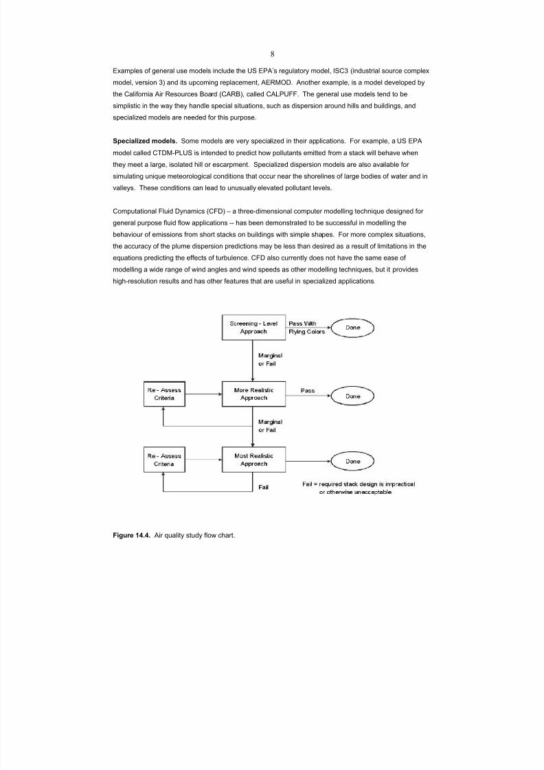
7/18/2019 Ventilation Guide
http://slidepdf.com/reader/full/ventilation-guide 222/223
'
K5B2A3 !"#"# J'1 U3,+'*. &*3$. 0+-5 <2,1*A
R=,/6+%& -0 (%"%1,+ 3&% /-$%+& '"<+3$% *2% QI ROJF& 1%(3+,*-1. /-$%+4 !IEY 9'"$3&*1',+ &-31<% <-/6+%=
/-$%+4 )%1&'-" Y; ,"$ '*& 36<-/'"( 1%6+,<%/%"*4 JRhLDWA J"-*2%1 %=,/6+%4 '& , /-$%+ $%)%+-6%$ 7.
*2% E,+'0-1"', J'1 h%&-31<%& V-,1$ 9EJhV;4 <,++%$ EJ]OQeeA B2% (%"%1,+ 3&% /-$%+& *%"$ *- 7%
&'/6+'&*'< '" *2% 5,. *2%. 2,"$+% &6%<',+ &'*3,*'-"&4 &3<2 ,& $'&6%1&'-" ,1-3"$ 2'++& ,"$ 73'+$'"(&4 ,"$
&6%<',+'M%$ /-$%+& ,1% "%%$%$ 0-1 *2'& 6316-&%A
G:3?54E5Q3< C9<3E1# I-/% /-$%+& ,1% )%1. &6%<',+'M%$ '" *2%'1 ,66+'<,*'-"&A e-1 %=,/6+%4 , QI ROJ
/-$%+ <,++%$ EBWLGO]QI '& '"*%"$%$ *- 61%$'<* 2-5 6-++3*,"*& %/'**%$ 01-/ , &*,<@ 5'++ 7%2,)% 52%"
*2%. /%%* , +,1(%4 '&-+,*%$ 2'++ -1 %&<,16/%"*A I6%<',+'M%$ $'&6%1&'-" /-$%+& ,1% ,+&- ,),'+,7+% 0-1
&'/3+,*'"( 3"'U3% /%*%-1-+-('<,+ <-"$'*'-"& *2,* -<<31 "%,1 *2% &2-1%+'"%& -0 +,1(% 7-$'%& -0 5,*%1 ,"$ '"
),++%.&A B2%&% <-"$'*'-"& <," +%,$ *- 3"3&3,++. %+%),*%$ 6-++3*,"* +%)%+&A
E-/63*,*'-",+ e+3'$ W.",/'<& 9EeW; j , *21%%G$'/%"&'-",+ <-/63*%1 /-$%++'"( *%<2"'U3% $%&'("%$ 0-1
(%"%1,+ 6316-&% 0+3'$ 0+-5 ,66+'<,*'-"& GG 2,& 7%%" $%/-"&*1,*%$ *- 7% &3<<%&&03+ '" /-$%++'"( *2%
7%2,)'-31 -0 %/'&&'-"& 01-/ &2-1* &*,<@& -" 73'+$'"(& 5'*2 &'/6+% &2,6%&A e-1 /-1% <-/6+%= &'*3,*'-"&4
*2% ,<<31,<. -0 *2% 6+3/% $'&6%1&'-" 61%$'<*'-"& /,. 7% +%&& *2," $%&'1%$ ,& , 1%&3+* -0 +'/'*,*'-"& '" *2%
%U3,*'-"& 61%$'<*'"( *2% %00%<*& -0 *3173+%"<%A EeW ,+&- <311%"*+. $-%& "-* 2,)% *2% &,/% %,&% -0
/-$%++'"( , 5'$% 1,"(% -0 5'"$ ,"(+%& ,"$ 5'"$ &6%%$& ,& -*2%1 /-$%++'"( *%<2"'U3%&4 73* '* 61-)'$%&
2'(2G1%&-+3*'-" 1%&3+*& ,"$ 2,& -*2%1 0%,*31%& *2,* ,1% 3&%03+ '" &6%<',+'M%$ ,66+'<,*'-"&A
7/18/2019 Ventilation Guide
http://slidepdf.com/reader/full/ventilation-guide 223/223
i
O2.&'<,+ /-$%++'"(4 3&'"( , &<,+% /-$%+ '" , 7-3"$,1.G+,.%1 5'"$ *3""%+4 '& *2% 7%&* &6%<',+'M%$ /-$%+ 0-1
&*3$.'"( $'&6%1&'-" 01-/ &2-1* &*,<@& '" 73'+* 36 *%11,'"A !* '& ,+&- 3&%03+ 0-1 &*3$.'"( $'&6%1&'-" '" ,1%,& -0
<-/6+%= *-6-(1,62.A !* <," ,<<-3"* 0-1 ,". 73'+$'"( (%-/%*1.4 "- /,**%1 2-5 <-/6+%= ,"$ '& 61,<*'<,+ 0-1
&'/3+,*'"( , 5'$% 1,"(% -0 5'"$ ,"(+%& ,"$ 5'"$ &6%%$&A e31*2%1 '"0-1/,*'-" -" 5'"$ *3""%+ /-$%++'"(
61-<%$31%& '& 61-)'$%$ '" 637+'&2%$ (3'$%+'"%& XiZA
!"#R )3@3A36?31
:A JE\!SA :iidA !"#$ &'( )*+$A J/%1'<," E-"0%1%"<% -0 \-)%1"/%"*,+ !"$3&*1',+ S.('%"'&*&4