Embed Size (px)
Citation preview
662580 DE/GB
09/02
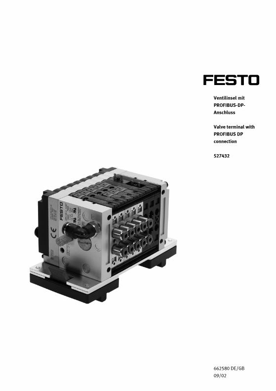
Ventilinsel mit
PROFIBUS-DP-
Anschluss
Valve terminal with
PROFIBUS DP
connection
527432
Best.-Nr.: 662580
Benennung: DATENBLATT
Bezeichnung: D:LP-VI-PROFIBUS-DE/GB
Stand: 09/2002
Autoren: Christine Löffler
Grafik: Doris Schwarzenberger
Layout: 04.09.2002 Beatrice Huber
© Festo Didactic GmbH & Co., D-73770 Denkendorf, 2002
Internet: www.festo.com/didactic
e-mail: [email protected]
Weitergabe sowie Vervielfältigung dieses Dokuments, Verwertung und
Mitteilung seines Inhalts verboten, soweit nicht ausdrücklich gestattet.
Zuwiderhandlungen verpflichten zu Schadenersatz. Alle Rechte
vorbehalten, insbesondere das Recht, Patent-, Gebrauchsmuster- oder
Geschmacksmusteranmeldungen durchzuführen.
The copying, distribution and utilization of this document as well as the
communication of its contents to others without expressed
authorization is prohibited. Offenders will be held liable for the payment
of damages. All rights reserved, in particular the right to carry out
patent, utility model or ornamental design registration.
Inhalt
Contents
© Festo Didactic GmbH & Co. • 662580 3
1. Aufbau_____________________________________________ 4
2. Funktion ___________________________________________ 6
3. Technische Daten ____________________________________ 8
1. Design _____________________________________________ 9
2. Function __________________________________________ 11
3. Technical data _____________________________________ 13
Deutsch
English
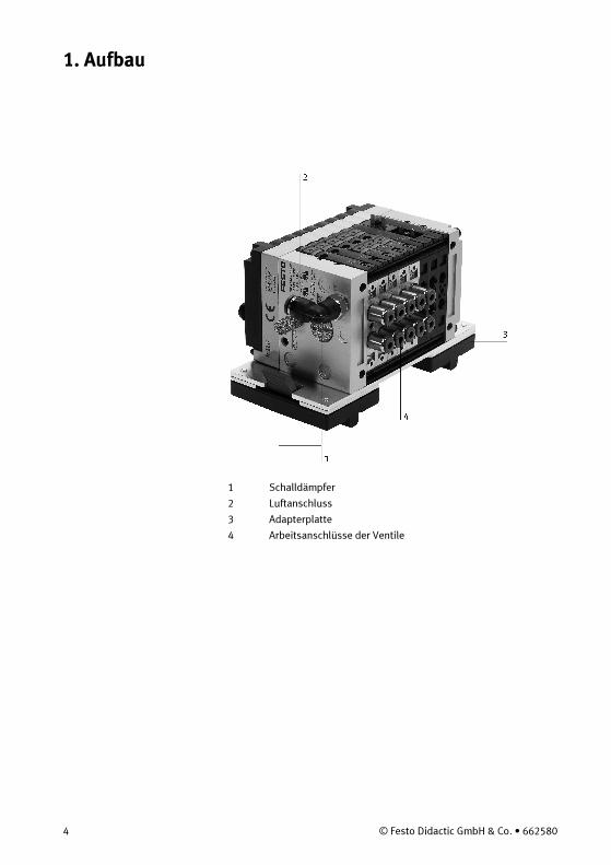
1. Aufbau
4 © Festo Didactic GmbH & Co. • 662580
1 Schalldämpfer
2 Luftanschluss
3 Adapterplatte
4 Arbeitsanschlüsse der Ventile
1. Aufbau
© Festo Didactic GmbH & Co. • 662580 5
5
6
10
11
7
89
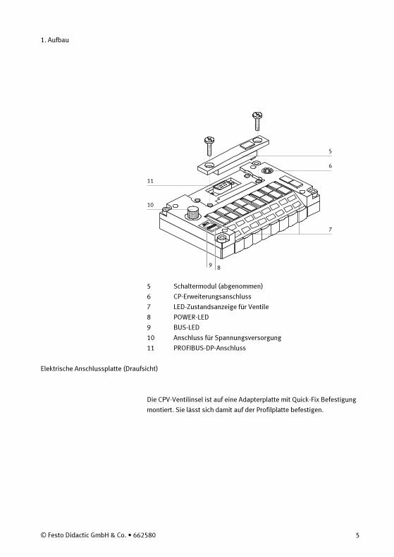
5 Schaltermodul (abgenommen)
6 CP-Erweiterungsanschluss
7 LED-Zustandsanzeige für Ventile
8 POWER-LED
9 BUS-LED
10 Anschluss für Spannungsversorgung
11 PROFIBUS-DP-Anschluss
Elektrische Anschlussplatte (Draufsicht)
Die CPV-Ventilinsel ist auf eine Adapterplatte mit Quick-Fix Befestigung
montiert. Sie lässt sich damit auf der Profilplatte befestigen.
2. Funktion
6 © Festo Didactic GmbH & Co. • 662580
• Die CPV-Ventilinsel mit PROFIBUS-DP-Direktanschluss ist
ausschließlich für den Einsatz in einem PROFIBUS-DP-Netz
bestimmt.
Die Ventilinsel ist erweitert um ein CP-Eingangsmodul mit 16
Eingängen für den Anschluss der Sensoren.
• Die Konfiguration der Ventilinsel stellen Sie mit den DIL-Schaltern
am Schaltermodul ein. Zur Konfiguration gehören:
– Feldbusprotokoll (PROFIBUS-DP)
– Erweiterung des CP-Systems
– PROFIBUS-Adresse
– Diagnosemode
• Die CPV-Ventilinsel mit PROFIBUS-DP-Anschluss ist mit folgenden
Platten bestückt: M M N E J L R L
– M: Ventilplatte mit 5/2-Wegeventil, monostabil und
federrückgestellt.
– N: Ventilplatte mit zwei 3/2-Wegeventilen in Grundstellung offen.
Mit den beiden 3/2-Wegeventilen kann die Funktion eines 5/3-
Wegeventils in Mittelstellung belüftet realisiert werden.
– E: Vakuumgenerator (Steuerseite 14) und ein 2/2-Wegeventil in
Grundstellung geschlossen (Steuerseite 12) für Abwurfimpuls.
Werkstücke mit glatter und dichter Oberfläche können angesaugt
werden.
– J: Ventilplatte mit 5/2-Wegeventil, Impuls.
– R: Relaisplatte mit Relaisspulen zur Ansteuerung von zwei
galvanisch getrennten Ausgängen.
– L: Reserveplatte ohne Ventilfunktion zum reservieren eines
Ventilplatzes.
CPV-Ventilinseln mit PROFIBUS-DP-Direktanschluss sind immer mit
4 oder 8 Ventilplatten bestückt. Aus diesem Grund sind zwei
Reserveplatten eingebaut.
2. Funktion
© Festo Didactic GmbH & Co. • 662580 7
• Bei Ansteuerung durch eine SPS:
– Anzahl der notwendigen SPS-Eingänge: 16,
– Anzahl der notwendigen SPS-Ausgänge: 10.
• Installationszubehör:
– Kabel für Spannungsversorgung mit drei 4 mm Sicherheitsstecker,
– Kabel zur Verbindung des CP-Erweiterungsmoduls mit der CPV-
Ventilinsel.
Bei nicht benutzten Ventilen verschließen Sie die Arbeitsanschlüsse 2
und 4 mit Blindstopfen.
Hinweis
3. Technische Daten
8 © Festo Didactic GmbH & Co. • 662580
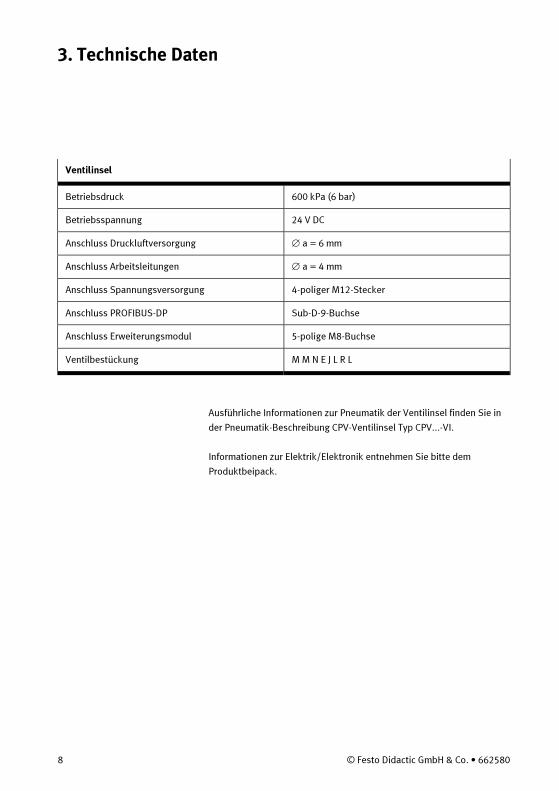
Ventilinsel
Betriebsdruck 600 kPa (6 bar)
Betriebsspannung 24 V DC
Anschluss Druckluftversorgung ∅ a = 6 mm
Anschluss Arbeitsleitungen ∅ a = 4 mm
Anschluss Spannungsversorgung 4-poliger M12-Stecker
Anschluss PROFIBUS-DP Sub-D-9-Buchse
Anschluss Erweiterungsmodul 5-polige M8-Buchse
Ventilbestückung M M N E J L R L
Ausführliche Informationen zur Pneumatik der Ventilinsel finden Sie in
der Pneumatik-Beschreibung CPV-Ventilinsel Typ CPV...-VI.
Informationen zur Elektrik/Elektronik entnehmen Sie bitte dem
Produktbeipack.

1. Design
© Festo Didactic GmbH & Co. • 662580 9
1 Silencer
2 Air supply connection
3 Adapter plate
4 Working ports of valves
1. Design
10 © Festo Didactic GmbH & Co. • 662580
5
6
10
11
7
89
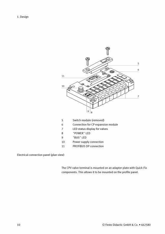
5 Switch module (removed)
6 Connection for CP expansion module
7 LED status display for valves
8 "POWER" LED
9 "BUS" LED
10 Power supply connection
11 PROFIBUS DP connection
Electrical connection panel (plan view)
The CPV valve terminal is mounted on an adapter plate with Quick-Fix
components. This allows it to be mounted on the profile panel.
2. Function
© Festo Didactic GmbH & Co. • 662580 11
• The CPV valve terminal with PROFIBUS DP direct connection is
intended only for use within a PROFIBUS DP network.
The valve terminal has been expanded to include a CP input module
with 16 inputs for the connection of sensors.
• The configuration of the valve terminal can be set by means of the
DIL switches on the switch module. The configuration includes the
following:
– Field bus protocol (PROFIBUS DP)
– Expansion of CP system
– PROFIBUS address
– Diagnostic mode
• The CPV valve terminal with PROFIBUS DP connection is equipped
with the following plates: M M N E J L R L
– M: Valve plate with 5/2-way valve, monostable with spring return.
– N: Valve plate with two 3/2-way valves, normally open.
The two 3/2-way valves can be used to produce the function of a
5/3-way valve, pressurised in its mid-position.
– E: Vacuum generator (pilot port 14) and a 2/2-way valve, normally
closed (pilot port 12) for ejector pulse. It is possible to pick up
workpieces with a smooth non-porous surface.
– J: Valve plate with 5/2-way valve, bistable.
– R: Relay plate with relay coils to control two electrically isolated
outputs.
– L: Reserve plate with no valve function as filler for a valve position.
CPV valve terminals with PROFIBUS DP direct connection are always
equipped with 4 or 8 valve plates. For this reason, two reserve
plates are fitted.
2. Function
12 © Festo Didactic GmbH & Co. • 662580
• When controlled by a PLC:
– Number of PLC inputs required: 16
– Number of PLC outputs required: 10.
• Installation accessories:
– Cable for power supply with three 4 mm safety plugs
– Cable to connect the CP expansion module to the CPV valve
terminal.
In the case of unused valves, seal working ports 2 and 4 with blanking
plugs.
Note
3. Technical data
© Festo Didactic GmbH & Co. • 662580 13
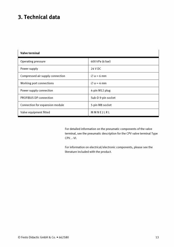
Valve terminal
Operating pressure 600 kPa (6 bar)
Power supply 24 V DC
Compressed air supply connection ∅ a = 6 mm
Working port connections ∅ a = 4 mm
Power supply connection 4-pin M12 plug
PROFIBUS DP connection Sub-D 9-pin socket
Connection for expansion module 5-pin M8 socket
Valve equipment fitted M M N E J L R L
For detailed information on the pneumatic components of the valve
terminal, see the pneumatic description for the CPV valve terminal Type
CPV...-VI.
For information on electrical/electronic components, please see the
literature included with the product.

14 © Festo Didactic GmbH & Co. • 662580