Embed Size (px)
Citation preview

Verification and Validation of FPGA Based Logic Controller
Dec. 6th , 2017
Jang Yeol Kim
0
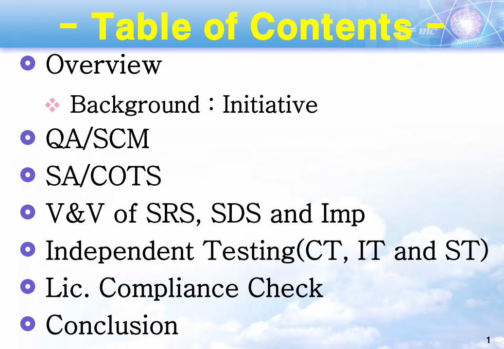
- Table of Contents - Overview
Background : Initiative
QA/SCM
SA/COTS
V&V of SRS, SDS and Imp
Independent Testing(CT, IT and ST)
Lic. Compliance Check
Conclusion1

Background
2
O Needed for 100% Coverage Test for Safety-critical Software
O Manual Test
- Not Cost Effective
- Too much longer time
O Needed Exhaustive Testing : Full PATH Testing if possible

Test Experience : Small Digital Devices
3
전류발생기
전압발생기
PS101-Q
4~20mAdc
0~10Vdc
모니터링 PCMY ICE
In-circuit emulator
Current : 6CH, Voltage : 2CH
ㅇ STEP(2~64) vs DT(01~99)- 2ms/STEP
ㅇ PUSH/Rotationㅇ Max/Min[Voltage : 0.1ms][Current : 1.0000V~5.ooV (250 Ohm))
(Automatic Signal Generator)

Manufacturing for Stimulator
4

Design : ANR, Testing : TER
V-Model Iteration and Re-Verification
V&V Schedule (V+V=W Model)
CTR/ITR, STR : Reporting for Dev. Prj :Anomaly Report(ANR), Test Exception Report (TER)(Test Case Generation/SW-SW, SW-HW, System, Target . Error Injection, Load Balancing / Burning Test -> Confirmation of Independent Verifier
2V Cycle V&V
Build Build
V&V1 V&V2 V&V3
1st Year 2nd Year 3rd Year
Dev
IV&V
5
Completion of FLC V&V
ANR Issues TER Issues ANR Issues TER Issues
6
Host Test Environment
Target Test Environment- Physical HW Chip Level,Board Level / System Level
(After Download)
(Before Download)
- Test Coverage (Exhaustive). Statement. Branch
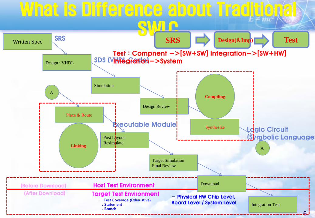
What is Difference about Traditional SWLC
Written Spec
Design : VHDL
Simulation
Design Review
Synthesize
Place & Route
Post LayoutResimulate
Target SimulationFinal Review
Download
Integration Test
A
ACompiling
Linking
SRS
SDS (VHDL Code)
Logic Circuit(Symbolic Language)
Executable Module
SRS Design(&Imp) TestTest : Compnent ->[SW+SW] Integration->[SW+HW] Integration->System
7
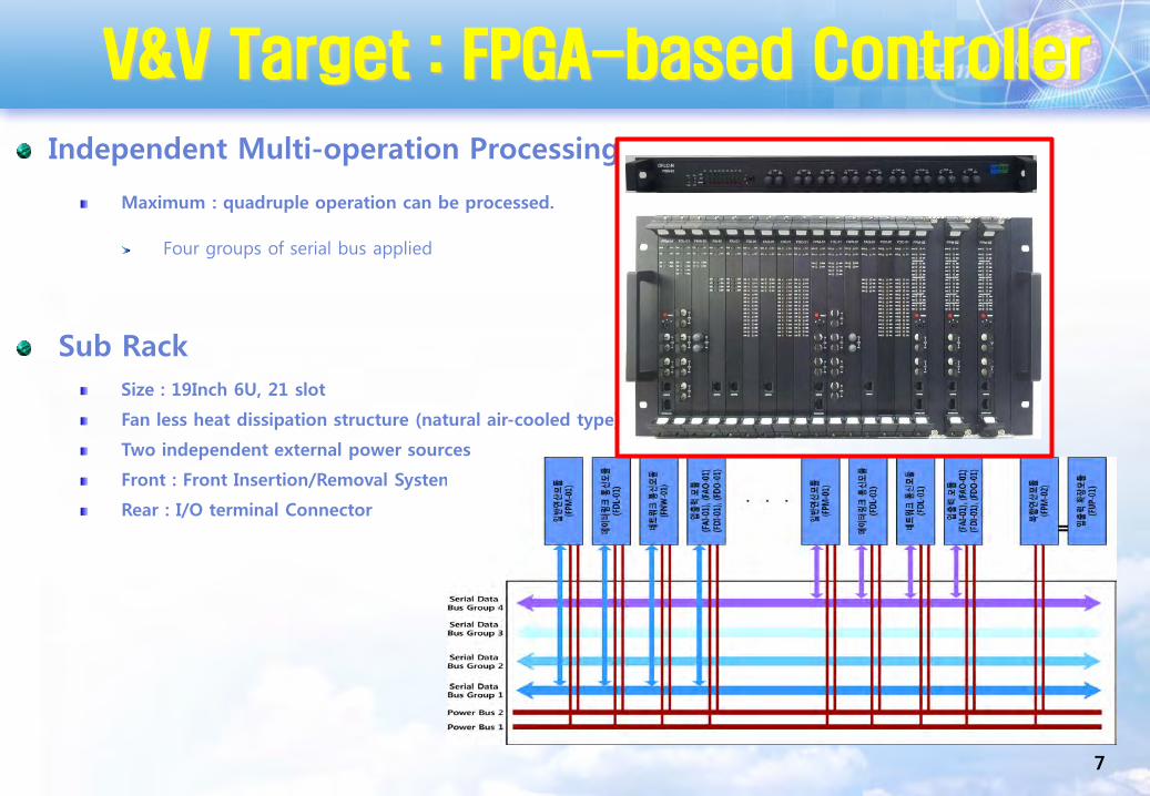
V&V Target : FPGA-based Controller
Independent Multi-operation Processing
Maximum : quadruple operation can be processed.
Four groups of serial bus applied
Sub RackSize : 19Inch 6U, 21 slot
Fan less heat dissipation structure (natural air-cooled type)
Two independent external power sources
Front : Front Insertion/Removal System
Rear : I/O terminal Connector

Licensing Requirement
Codes
RegulatoryGuide
IndustrialCode & Std.
IEC 61513-2001(General req.)
NUREG/CR-6463 EPRI TR-106439-1988
(Digital COTS evaluation)
10 CFR 50 App. A (GDCs)
Planning
830-2012(Req. spec.)[EME 3200]
1016-19981016-2009
(Design Spec.)
1016.1-1993 (Design spec. gl)
Design(Coding)
1008-1993(Unit test)[EME 3500]
V&V
577-2012(Reliability anal.)
[ENB 4200]
982.1&2-1988 (SW Measures)
1044-2009 (Anomalies class)
Etc.RG 1.169 - 2013
(CMP) RG 1.168-2013 (V&V, audit)RG 1.170-2013 (Test docum.)
RG 1.171 -2013(Unit test)
Req. spec.RG 1.172 - 2013
(Req. spec.)
EPRI NP-5652(COTS Guideline)
983-1986 (QA plan guideline)
IEEE 603 (Safety sys.)RG 1.153-2003
RG 1.173-2013(Development of
LCP)
LCP
10CFR 50.55a(h) (Safety sys. criteria) 10 CFR 50 App. B (QA)
1059-1993 (V&V guideline)
829-2008 (Test docum.)[EME 3600]
RG 1.28-2010 (QA)
Installation
IEC 60880-2006 (Safety S/W)
ANSI/IEEE 7-4.3.2-2003RG 1.152-2006
Standard Review Plan – NUREG-0800 (Ch. 7 & BTP-14)
NUREG/CR-6101NUREG/CR-6421
352-1987(Reliability anal.)
[ENB 4100]
1046-1991(Application guide)
1042-1987 (CM guideline)
[EME 3310]
1074-2013(Life cycleProcess)
[EME 3400]
1012-2004(V&V)
[EME 3100]
1058-1998(Manag. plan)
828-2012(CM plan)[EME 3300]
1228-1994(Safety plan)[EME 3800]
730-2002(QA plan)
[EME 3900]
1219-1998 (Maintenance)
1061-1998 (Quality metrics)
1540-2001 (Risk
management)
IEEE
IEC 62138-2004 (Category B,C S/W)
KEPIC
1028-2008(Review&Audit)
[EME 3700]
IAEA
KS
60여종
NUREG/CR-6430Guidance
8
IEC Std-62566
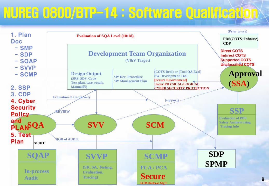
Approval(SSA)
PDS(COTS+Inhouse)CDP
SQA SVV SCM
Development Team Organization(V&V Target)
Design Output(SRS, SDS, CodeTest plan, case, result, Manual등)
SW Dev. ProcedureSW Management Plan
(COTS Dedi) or (Tool QA Eval)SW Development Tool[Secure Environment]Under PHYSICAL/LOGICALCYBER SECURITY PROTECTION
(Prior to use)Evaluation of SQA Level (10/18)
SDPSPMP
SQAP SVVP SCMP
Evaluation of Conformity
REVIEW
In-processAudit
FCA / PCA
Secure SCM+Release Mg’t
(SR, SA, Testing,Evaluation,Tracing)
SSPEvaluation of PDSSafety Analysis usingTracing Info
AUDITDOR of AUDIT
(support)
1. Plan Doc
- SMP- SDP- SQAP- SVVP- SCMP
2. SSP3. CDP4. Cyber Security Policyand
PLAN5. Test Plan
Direct COTSIndirect COTSSupported COTSUnclassified COTS
NUREG 0800/BTP-14 : Software Qualification
9

10
Quality Assurance Activity
• Safety and Reliability against CCF
• Licensing Suitability
•QA Coordinator- All Prj Members
• Operation and Maintenance of QAP/QA Proc.. Education and Training / Staff Qualification
• QA Rec. Review• QA Audit/QA Inspection
• CAR Issue and Closing• Mg’t of NCR(From ANR Issue to Closing)• QA Education and Training
P
D
C
A
Continuous Improving
• Working according to QAP- Mg’t of Design Doc
Preparing/Review/Approval
QualityPolict
QA Plan
QA Procedure
Working Doc(All Plans Doc, Reports))
ㅇ 10CFR50 Appendix B- ASME/NQA-1-2008, Agenda-2009- (KEPIC-2011 Appendix Full Revision)

From ANR/TER issues Opening to Closing
Distribution List The example of baseline list
11

Quality Evaluation of COTS SWCOTS SW Dedication 대상 (by NP-5652/TR-106439 + KINS/RG-
17.12)
Direct SW
Indirect SW : Ex) Compiler, Environment Toolset
o NUREG/CR-6421 : Too Strict
o EPRI-NP-5652 : HW
o EPRI-TR-106439 : HW+SW
Logic Synthesis
by
SRS and SDS
RTL Design(Verilog or VHDL)
Gate-Level Design
(Netlist)
Layout
Synplify Pro
Precision RTL
Microsemi Libero SoC 11.5
FPGA
Equivalence Checking
by FormalPro
or
Equivalence Checking
by CVEC
O Methods - Special Purpose Testing : Method 1- Commercial Grade Survey : Method 2
. Product Development Record- Source Verification : Method 3- Operating Experience Data : Method 4
. Correctness
. Performance
. Software QualitiesIn case of COTS Software : Applicable to Method 2 & Method 4
EC360/One Spin
12

Approaching Safety Analysis Plan Safety Analysis Guideline Deviation : DFLC-N Characteristics Experiences from Past Projects Tracking of V&V Test Results Follow-Up
Safety Analysis of FLC
Deviation
HW Initialization Fail
Memory Initialization Fail
Parameter Setup Missing
Initialization Fail for I/O Updating
Malfunction of FPGA
Stuck at all zeros of ROM/RAM
Memory partition assignment fail
WDT Error
DeviationExecution Error for Functional Spec
Fail for Reset and Clock Generation Function
Violation of Trigger Condition for Reset and Clock Generation
Termination Violation of Reset and Clock Generation
Fail for Operating Voltage Monitoring
Violation of Trigger Condition for Operating Voltage Monitoring
Termination Violation of for Operating Voltage Monitoring
Fail of Memory Setup and Diagnostics
Violation of Trigger Condition for Memory Setup and Diagnostics
Termination Violation of Memory Setup and Diagnostics
Fail of Inter-Module Data Interface
Violation of Trigger Condition for Inter-Module Data Interface
Termination Violation of for Inter-Module Data Interface
Fail of Data Diagnostics
Violation of Trigger Condition for Data Diagnostics
Violation of Termination Condition for Data Diagnostics
13

Safety Analysis and Safety Test based on Recommended Deviation
Deviation Recommendatiopn
Execution Error for Functional SpecConfirmation with V&V of Testing Phase
Fail for Operating Voltage Monitoring “
Violation of Trigger Condition for Operating Voltage Monitoring
“
Termination Violation of for Operating Voltage Monitoring
“
Fail of Memory Setup and Diagnostics “
Violation of Trigger Condition for Memory Setup and Diagnostics
“
Termination Violation of Memory Setup and Diagnostics
“
Fail of Inter-Module Data Interface “
Violation of Trigger Condition for Inter-Module Data Interface
“
Violation of Trigger Condition for Inter-Module Data Interface
“
Fail of Data Diagnostics “
Violation of Trigger Condition for Data Diagnostics
“
Violation of Termination Condition for Data Diagnostics
“
Test Input
Test Output
Safety Analysis of FLC
14

SRS/SDS V&V Report[1]1. V&V Method and Criteria
• V&V Activities for SRS– IEEE Std 1012 + IEC 62566– NUREG 0800 Chapter 7/BTP-14
• Functional and Process Characteristics
Relationship of IEC 62566 and IEEE 1012IEC 62566 Phase IEEE Std 1012-2004 Comments
6.6.1
SRS
- Traceability- SRS Evaluation : Correctness, Completeness, Accuracy, Testability- Interface Analysis : Correctness, Consistency
6.6.2- Traceability- SRS Evaluation - Interface Analysis
6.6.3- SRS Evaluation : Consistency, Completeness, - Interface Analysis : Consistency, Completeness
6.6.4 - IEEE Std 1012 Appendix C V&V Independence Technical, Manageable
9.4.1 a)
SDS
- Traceability- Design Evaluation : Completeness, Consistency- Interface Analysis : Completeness, Consistency
9.4.1 b)- Design Evaluation : Readability, Testability- Interface Analysis : Testability
9.4.1 c)- Traceability- Design Evaluation : Correctness, Consistency, Completeness- Interface Analysis : Correctness, Consistency, Completeness 15
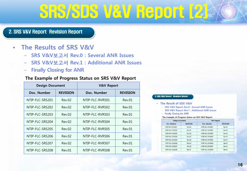
SRS/SDS V&V Report [2]2. SRS V&V Report Revision Report
The Example of Progress Status on SRS V&V Report
• The Results of SRS V&V– SRS V&V보고서 Rev.0 : Several ANR Issues– SRS V&V보고서 Rev.1 : Additional ANR Issues– Finally Closing for ANR
Design Document V&V Report
Doc. Number REVISION Doc. Number REVISION
NTIP-FLC-SRS201 Rev.02 NTIP-FLC-RVR501 Rev.01
NTIP-FLC-SRS202 Rev.02 NTIP-FLC-RVR502 Rev.01
NTIP-FLC-SRS203 Rev.02 NTIP-FLC-RVR503 Rev.01
NTIP-FLC-SRS204 Rev.02 NTIP-FLC-RVR504 Rev.01
NTIP-FLC-SRS205 Rev.02 NTIP-FLC-RVR505 Rev.01
NTIP-FLC-SRS206 Rev.02 NTIP-FLC-RVR506 Rev.01
NTIP-FLC-SRS207 Rev.02 NTIP-FLC-RVR507 Rev.01
NTIP-FLC-SRS208 Rev.01 NTIP-FLC-RVR508 Rev.01
16

Code V&V Report1. V&V Method and Criteria
• SRS Criteria Compiling– IEEE Std. 1012 based Quality Attributes Measurement between Source Code and
Implementation Specification– NUREG 0800 Chapter 7/BTP-14 Acceptable Criteria
• Licensing Suitability.
– NUREG/CR-70061) 기Code Inspection based on Coding Guideline
Quality attributes
Reliability
Robustness
Traceability
Maintainability
1) FAM-01NUREG CR-7006 : Review Guidelines for Field-Programmable Gate Arrays in Nuclear Power Plant Safety Systems
NUREG/CR-7006 Quality Attributes
Traceability AnalysisSource code and source
code documentation evaluation
Interface Analysis
Correctness Correctness Correctness
Consistency Consistency Consistency
Completeness Completeness Completeness
Accuracy Accuracy
Readability Testability
Testability
IEEE Std 1012 Quality Attributes
17

Component TestComponent Test Procedure
ImplementTestbench
ImplementDesign
Synthesis
Place & Route
Load FPGA
RTL
HW Design Spec
Systemrequirements
Test Plan
Testbench
Bitstream
Static verification
Static Timing Analysis
Using Smarttime
Equivalence CheckUsing OneSpin
Functional TestCode Coverage
AnalysisUsing QuestaSim
stimulusSeq
actualSeq
expectedSeqSeq
Seq
Seq
Seq
Match ?OrMismatch ?
18
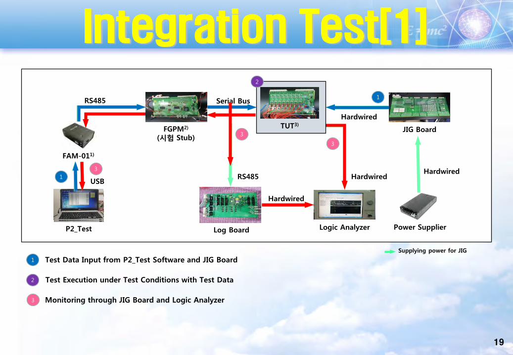
Integration Test[1]
Supplying power for JIG
Logic Analyzer
Hardwired
Serial Bus
P2_Test
FAM-011)
Power Supplier
Hardwired
JIG Board
Log Board
RS485USB
RS485
Hardwired
Hardwired
FGPM2)
(시험 Stub)
Test Data Input from P2_Test Software and JIG Board1
Test Execution under Test Conditions with Test Data2
Monitoring through JIG Board and Logic Analyzer3
TUT3)
1
1
2
3
3
3
19

Integration Test[2]◄ Test Execution Flow
Real Target Boards► Integration Test Environment
Logic Analyzer
Input/OutputSerial Bus
P2_TESTFAM
Signal MeasurementFAM-01
`
FAM-01
RS485
Fluke 755
Voltage/CurrentSupply and
Measurement
GPM(Test Stub)
JIG Board
Log Board
시험대상모듈
RS485
QA Audit DEMO
20
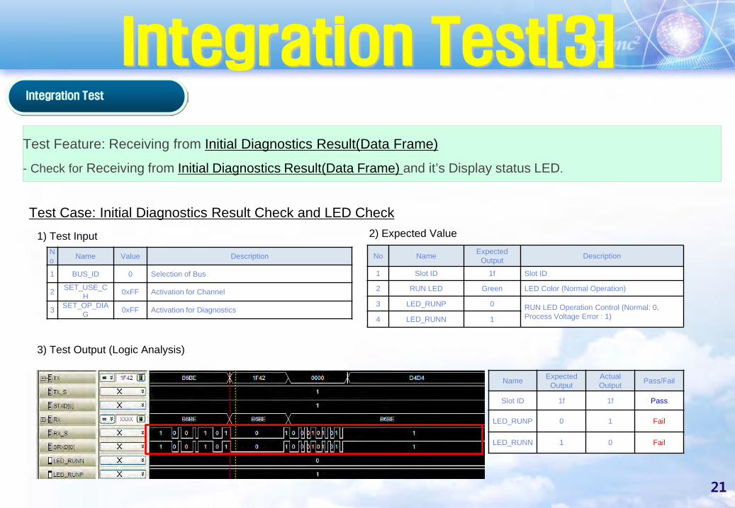
Integration Test[3]Integration Test
3) Test Output (Logic Analysis)
Test Feature: Receiving from Initial Diagnostics Result(Data Frame)- Check for Receiving from Initial Diagnostics Result(Data Frame) and it’s Display status LED.
Test Case: Initial Diagnostics Result Check and LED Check
No Name Expected Output Description
1 Slot ID 1f Slot ID
2 RUN LED Green LED Color (Normal Operation)
3 LED_RUNP 0 RUN LED Operation Control (Normal: 0, Process Voltage Error : 1)4 LED_RUNN 1
No Name Value Description
1 BUS_ID 0 Selection of Bus
2 SET_USE_CH 0xFF Activation for Channel
3 SET_OP_DIAG 0xFF Activation for Diagnostics
1) Test Input 2) Expected Value
Name Expected Output
Actual Output Pass/Fail
Slot ID 1f 1f Pass
LED_RUNP 0 1 Fail
LED_RUNN 1 0 Fail
21
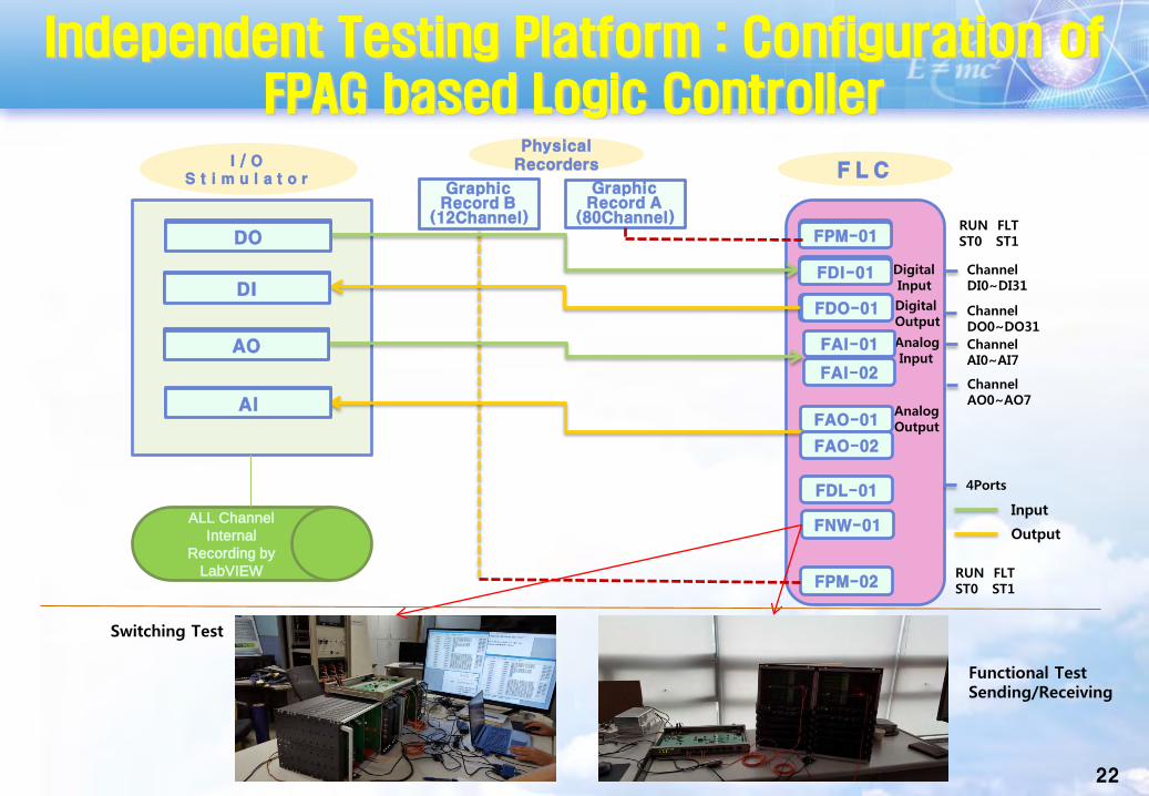
Independent Testing Platform : Configuration of FPAG based Logic Controller
22
Input
Output
AO
DI
DO FPM-01
F L CI / O
S t i m u l a t o rGraphic Record B
(12Channel)
Graphic Record A
(80Channel)
PhysicalRecorders
AnalogInput
FDO-01
FAI-01
FAO-01
FDI-01
FDL-01
AnalogOutput
DigitalInput
DigitalOutput
AI
AO
DI
DO FPM-01
FDO-01
FDI-01
AI
ChannelDI0~DI31
ChannelDO0~DO31
RUN FLTST0 ST1
ChannelAI0~AI7
ChannelAO0~AO7
RUN FLTST0 ST1
ALL Channel Internal
Recording by LabVIEW
FPM-02
FNW-01
FAI-02
FAO-02
4Ports
Functional TestSending/Receiving
Switching Test

23
Integration Test
1st REC2nd REC
Target FLC
1. I/O Stimulator Platform Qualification- Y=aX Linear Function, 10,000 test case, Full Scale
3. Pre-Qualification by Manual- Fluke 754- 1st REC, 2nd REC
4. Scenario based Input/Output Automatic Testㅇ FAI-> Internal Bus->FPM01-> FDL-> FAOㅇ FDI-> Internal Bus->FPM01-> FDL-> FDOㅇ FAI-> Internal Bus->FPM01-> FDL-> FDO (cross)ㅇ FDI->Internal Bus-> FPM01-> FDL-> FAO
• (Triangle : 0-Rising-Falling-0 : 10,000 Test Case, 200ms, 01.%)
5. Test Result and Analysis
Status MonitoringScreen
Testing ScenarioSystem Test
DEMO

24
System Test for FLC
Target FLC
Automatic Signal Generator- Manual Test- Automatic Test by initiating Manual
Test Result- Pass/Fail - Real-time Performance
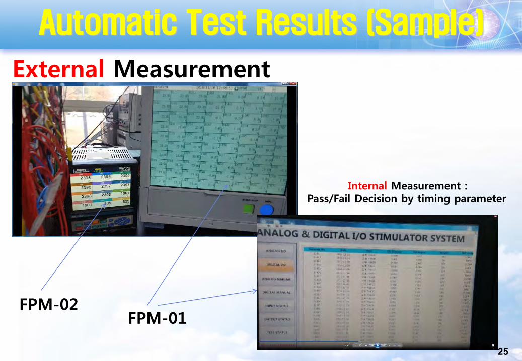
Automatic Test Results (Sample)
25
Internal Measurement :Pass/Fail Decision by timing parameter
External Measurement
FPM-02FPM-01
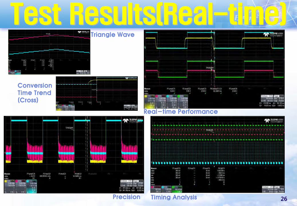
Test Results(Real-time)
ConversionTime Trend(Cross)
Triangle Wave
Timing Analysis
Real-time Performance
Precision 26
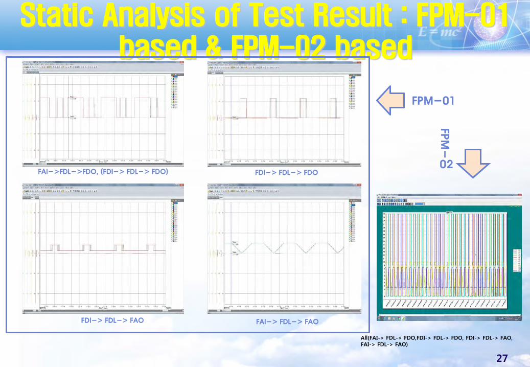
Static Analysis of Test Result : FPM-01 based & FPM-02 based
FAI->FDL->FDO, (FDI-> FDL-> FDO) FDI-> FDL-> FDO
FDI-> FDL-> FAO FAI-> FDL-> FAO
All(FAI-> FDL-> FDO,FDI-> FDL-> FDO, FDI-> FDL-> FAO,FAI-> FDL-> FAO)
FPM-01
FPM
-
02
27

Licensing Suitability : Compliance Check
28
Conclusions
29
QA/SQA/SCM
COTS Dedication/Tool Quaity Evaluation
SA
SVV : Independent Testing
Automatic Testing!!!

30
Future Plans
IoT+AI
Producing Verification Data
Clouds/Cluster
ㅇ Sensors- Press- Level- Temp
. RTD, Bimetal
- Relay