Embed Size (px)
Citation preview

This article was downloaded by: [Csumb Calif State Univ]On: 21 November 2014, At: 12:16Publisher: Taylor & FrancisInforma Ltd Registered in England and Wales Registered Number: 1072954 Registeredoffice: Mortimer House, 37-41 Mortimer Street, London W1T 3JH, UK
Journal of Nuclear Science andTechnologyPublication details, including instructions for authors andsubscription information:http://www.tandfonline.com/loi/tnst20
Verification Method of Software forMicroprocessor-Based Protection Systemof Nuclear Power PlantsSatoshi SUZUKI a , Yukio NAGAOKA a , Shigeru IZUMI a & Tetsuo ITO aa Energy Research Laboratory , Hitachi Ltd. , Moriyama-cho, Hitachi-shi , 316Published online: 15 Mar 2012.
To cite this article: Satoshi SUZUKI , Yukio NAGAOKA , Shigeru IZUMI & Tetsuo ITO (1989) VerificationMethod of Software for Microprocessor-Based Protection System of Nuclear Power Plants, Journal ofNuclear Science and Technology, 26:3, 313-320, DOI: 10.1080/18811248.1989.9734312
To link to this article: http://dx.doi.org/10.1080/18811248.1989.9734312
PLEASE SCROLL DOWN FOR ARTICLE
Taylor & Francis makes every effort to ensure the accuracy of all the information (the“Content”) contained in the publications on our platform. However, Taylor & Francis, ouragents, and our licensors make no representations or warranties whatsoever as to theaccuracy, completeness, or suitability for any purpose of the Content. Any opinions andviews expressed in this publication are the opinions and views of the authors, and arenot the views of or endorsed by Taylor & Francis. The accuracy of the Content should notbe relied upon and should be independently verified with primary sources of information.Taylor and Francis shall not be liable for any losses, actions, claims, proceedings, demands,costs, expenses, damages, and other liabilities whatsoever or howsoever caused arisingdirectly or indirectly in connection with, in relation to or arising out of the use of theContent.
This article may be used for research, teaching, and private study purposes. Anysubstantial or systematic reproduction, redistribution, reselling, loan, sub-licensing,systematic supply, or distribution in any form to anyone is expressly forbidden. Terms &Conditions of access and use can be found at http://www.tandfonline.com/page/terms-and-conditions

Journal Of NUCLEAR SCIENCE and TECHNOLOGY, 26(3], pp. 313-320 (March 1989). 313
Verification Method of Software for Microprocessor
Based Protection System of Nuclear Power Plants
Satoshi SUZUKI, Yukio NAGAOKA, Shigeru IZUMI and Tetsuo ITO
Energy Research Laboratory, Hitachi Ltd.*
Received january 19, 1988 Revised September 14, 1988
This paper proposes a new concept for efficient verification of software for the protection systems of nuclear power plants. In this idea, all possible input combinations are applied to each module comprising the software and the module responses are compared with their correct responses which are provided beforehand. To realize the concept, algorithms have been developed for observing module responses through an external tester and for generating a quasi minimal test pattern set capable of testing all modules.
This approach remarkably reduces the number of required test input combinations in comparison with that of the combinations without observation of module outputs. In addition, most software errors are expected to be uncovered more efficiently with Jess effort and time.
KEYWORDS: microprocessors, reactor protection systems, reactor safety, software, integrity, verification, testability, module outputs, test pattern reduction, test generation, error detection
I. INTRODUCTION
The electrical power industry has been increasing the use of microprocessors in plant control systems in step with advances in microelectronics technology. The industry has been particularly interested in the benefits to be derived from new uses in nuclear safety protection systems. In order to realize microprocessor-based nuclear protection systems, it is important to establish highly reliable protection software because these systems are essential to detection of abnormal plant conditions and initiation of safety system actions. In conventional hardware logic protection systems, high reliability has been attained easily by use of a redundant design technique<'>. Application of such a technique to software reliability has also been considered<2>-<•>, however, this is not as easy as for the hardware system, because redundant software must be designed so as not to include common mode errors.
As another approach, some development methods for producing reliable software have
been proposed, and they are also applicable to protection software<5>-<'2>. A problem yet remaining is that a great number of test cases are required in the test phase.
To resolve this problem, the basic concept for an efficient method for testing the protection software was proposed<' 3>. In the concept, the microprocessor-based protection system for nuclear plants is a functional replacement for the hardware logic protection system. Therefore, if the protection software is composed of small modules corresponding to hardware logic elements, such software can be tested as if hardware logic systems were being tested. To realize this idea, the module outputs should be observable. The integrity of each module can be examined by probing the module outputs and correct module responses to test inputs can be provided beforehand based on logic specifications. If every module response is correct over all its possible input combinations, the protection software is verified.
Generally, the number of test input combinations required for system verification is * Moriyama-cho, Hitachi-shi 316.
-7-
Dow
nloa
ded
by [
Csu
mb
Cal
if S
tate
Uni
v] a
t 12:
16 2
1 N
ovem
ber
2014

314
equal to the number of the relationships between the input and output of all modules which must be verified. Considering only two-value data, the number of required test input combinations Nr is:
M Nr= 2J (Number of K input modules)X2K,
K=l
(1)
where M is the maximum number of module inputs. This number is very small in comparison with the number of combinations 2N required for the case without observing module outputs, when the number of module inputs K is small (N: Number of system inputs). For example, the number of test input combinations required to test an AND module with 100 inputs is 2100
( ~1030 ), without observing module outputs, and only 99X22 (~400) in the new approach, since the AND module is
Processing unit y ~nitial timer:::::::=:-
'5 .e-
VesT Additional software for investigating memory addresses of mod.Jie output variables
- ---~ Acquisition of ifl)ut data
I Calculation of protection logic
I System output
b. ' . .
]. Nucl. Sci. Technol.,
composed of 99 AND modules with 2 inputs. This paper discusses methods for observing
module outputs, without introducing additional errors into the main software, and methods for generating the quasi minimal test pattern sets.
ll. METHOD
1. Observation of Module Outputs Reading out the module outputs is essential
to the proposed approach. The conventional method for observing module outputs requires insertion of debugging statements in the software to be tested. However, this is undesirable in protection software requiring high reliability, since the debugging statements must be deleted after verification of the software and this may introduce new errors.
In order to overcome this defect, a better approach is proposed and is illustrated in Fig. 1.
Dual port memory
-
Terminals to external tester
Process output device
Fig. 1 System design concept for observation of module outputs
The main features of the approach are newly added software and a dual port memory. The additional software reads out from the memory the absolute addresses of the module output variables used in the protection software. This software, then, writes in the memory a table of the variable names and their corresponding addresses. Thus, the values of module output variables can be observed by an external device. This external device can initially obtain the variable-address
information from the memory. Then, by referring to this information, the device can correctly read out the values of the module output variables.
The above additional software can be easily implemented on the C programing language as illustrated in the example of Fig. 2. In this language, variables prefixed with the symbol & can be treated as their absolute addresses. So, the address of a module output variable used in the protection software
-8-
Dow
nloa
ded
by [
Csu
mb
Cal
if S
tate
Uni
v] a
t 12:
16 2
1 N
ovem
ber
2014

Vol. 26, No. 3 (Mar. 1989) 315
static long •table = xxxxxx; /•table address•/
and the name of the variable as the other argument of the subroutine. The subroutine called "adrtble" first writes the variable name and its address into the table area preassigned on the memory and then the address of the table area is increased for the next variable name and its address. If the subroutine is called for all module output variables, the table of variable names and their addresses can be accomplished.
main( {
int var(100): long xaddr:
xaddr = table: adrtble l"var(1)", &var(1J): adrtble("var(2J", &var(2J):
logic program
adrtblelvname, vaddr) char •vname: long vaddr: This additional software is run only once
to prepare the table before periodic runs of the protection software. Consequently, it does not affect the protection software to be tested and it does not need to be removed after the verification.
{ strncpy(table,vname, 8): table++: table++: •table .. vaddr: table++:
Fig. 2 Example of additional software using C language
2. Test Pattern Generation can be identified by a subroutine rece1vmg a variable name with & as one of the arguments
In order to test the protection software by the proposed method, first, all possible input
_y I Readout of logic specifications and ordering I
the variables of modules used
I l lnitializaticn of ~asi minimal test pattern set I
I lSelection of 1st module, lm, for rn=1 I according to the order assigned to modules
I Generation of module test pattern set,T(Im) I r - - - - - - - - - - - - - - - - - - - -j- - - - - - - - - - - - - - - - - - - - - -
l Selection of a pattern, TiiET(Im)), for i=1 1
I General ion of a new pattern by intersection I of T i and an elernS'lt of ~asi minimal test pattern set, MT (Jm-1)
No >is 'f< New pattern exists ?
Determination of unspecified !Addition of the new pattern I values in pattern T i to new quasi minimal test by back tracing method pattern set, MTUml
I ConsistS'!! values No
-, I I I
can be assigned ? I ~Selection of I Yes j next pattern
Addition of obtained pattern ~Labelling I Ti,for i=i+1
to new quasi minimal test the pattern as pattern set , MT ( lm) non-existent
I L - --, I S 1 . f I : Pattern Ti 1s f 1nal element
No e ect1on o 1 in set T llml ?
next module 1 •
lm, for m=m+1 L ___________ ! ~e~ _____________ Y ______
I I I I I I I I I
.J
I ......_ lm IS final module ? Generation of quasi No [:;,v mn1mal test pattern s
Yes et
Fig. 3 Outline of computational flow for test pattern generation
-9-
Dow
nloa
ded
by [
Csu
mb
Cal
if S
tate
Uni
v] a
t 12:
16 2
1 N
ovem
ber
2014
316
combinations to each module must be generated, and secondly correct responses of each module must be provided. In principle, the number of all possible combinations is given by Eq. ( 1 ). However, this can be further reduced by an appropriate selection of primary inputs, or system inputs. This selection is tedious work, so it is useful to devise a tool which generates a minimal or a quasi minimal set of the test pattern. For this purpose, a method for generating the quasi minimal test pattern set is developed for combinational logics. The algorithm is roughly illustrated in Fig. 3.
( 1 ) Ordering First, all input and output variables of
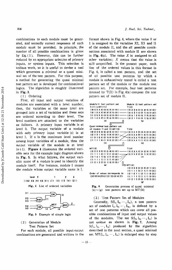
modules are associated with a level number, then, the variables at the same level are grouped into a set of variables and these sets are ordered according to their level. The level numbers are attached to the variables as follows. A primary input variable is at level 0. The output variable of a module with only primary input variable (s) is at level 1. If n is the maximum level number among input variables of a module, then the output variable of the module is at level (n+1). Figure 4 illustrates the ordered variable sets for the example logic diagram shown in Fig. 5. In what follows, the output variable name of a module is used to identify the module itself. For instance, module I means the module whose output variable name is I.
level 0 I 2 3
((X2 X3 X4 XS XI) ill 12) 113 14) IZ)J
Fig. 4 List of ordered variables
XI
X2 X3
X4 xs
Fig. 5 Example of simple logic
( 2) Generation of Module Test Pattern Set
For each module, all possible input-output combinations are generated and written in the
]. Nucl. Sci. Techno/.,
format shown in Fig. 4, where the value 0 or 1 is assigned to the variables X2, X3 and 11 of the module 11, and the all possible combinations associated with module 11 are shown in Fig. 6(a). The value X is assigned to all other variables; X means that the value is still unspecified. In the present paper, each line of the ordered values in this format in Fig. 6, is called a test pattern, and the set of all possible test patterns by which a module is exhaustively tested is called a test pattern set of the module or the module test pattern set. For example, four test patterns denoted by T(11) in Fig. 6(a) compose the test pattern set of module Il.
Module 11 test pattern set Module 12 test pattern set T!l1) (=MTII1)) Tll2) ( 10 0 X X Xl (0 Xl IX Xl IX)) -- I IX X 0 0 Xl IX 0) ()( X) IX)) I 10 I X X X) 10 X) IX X) (X)) -- (IX X 0 I X) IX I) IX X) ()()) ((! OXXX)IOX)(XX)(X))--((XX 1 OXl(X I)IXX)(X)) ( (I 1 X X Xl I 1 X) (X Xl IX)) -- ( (X X I I XI (X 1) (X Xl (X) )
(a) n (b)
{} Quasi minimal test pattern set of module 11 and 12,MTII21 T!l3) ((0 0 0 0 Xl (0 0) (X Xl IX)) ~<<X X X X 0) 10 Xl (0 X) (X)) ( (0 1 0 1 XI 10 1) (X X) (X)) / ((X X X X 0) (I Xl II X) (X)) 111 0 I 0 Xl (0 1) (X XI IX)) ~((X X X X!) (0 X) (I X) IX)) ((1 I I I X)(11)(XX)(XII/---((XXXX 1)(1 X)(! XIlX)}
(C) 0 (d)
MT(I3) u T(l4) ({0 0 0 0 0) 10 0) 10 Xl (X))-- ((X X X X X) (X 0) (X ll (X)) ( (1 I I I 01 (! 1) (1 X) (X)) ---;:::oo( (X X X X X) (X !) IX 0) (X)) ((0 I 0 I ll (0 I) (1 Xl (X))-:~~: (f)
I I 1 I I 1 ll (! ll (! X) IXl ) ' / ( (! 0 1 0 01 10 I l 10 Xl IX)) ' n
(e) ~MTII4) ( (0 0 0 0 0) 10 0) (0 1) (Xl) (11 I 11 0)1!1)(1 O)(X))
Order of values corresponds to ( (0 I 0 1 I) (0 I) (! 0) (X)) ((X2X3X4XSX!l(l1 12)(13 1411ZJI ((1 1 1 1 I) (I II(! 0) (X))
( (I 0 1 0 0) (0 1) 10 0) (X)) (g)
Fig. 6 Generation process of quasi minimal (a)- (g) test pattern set up to MT (14)
( 3 ) Test Pattern Set of Modules Generally, S(It, I21 ••• , Im), a test pattern
set of modules Il> I21 • • • , Im, is defined by a set of test patterns which can cover all possible combinations of input and output values of the modules. The set S(ll> I21 • • • , Im) is not unique as shown in Fig. 7. Among S(ll> I2, · · · , Im) produced by the algorithm described in the next section, a quasi minimal set MT(I~> I2, · · · , Im) is enlarged step by step
-10-
Dow
nloa
ded
by [
Csu
mb
Cal
if S
tate
Uni
v] a
t 12:
16 2
1 N
ovem
ber
2014

Vol. 26, No. 3 (Mar. 1989)
by increasing the number of modules by one each step from lower to higher levels. The initial quasi minimal set is a test pattern set of any module at level 1. In fact, it is a minimal set, since no subset of the initial set covers all possible combinations of input and output values of the module. In the example of Fig. 5, the initial quasi minimal set is the test pattern set of module 11, which is the first module at level 1 in the ordered variable set.
((X2 X3 X4 XS X1J (11 12) (13 14) (ZJJ ( ( 0 0 0 0 X J ( 0 0 J ( X X ) (X) J ( ( 0 1 1 0 X l ( 0 1 ) ( X X ) (X) ) ( ( 1 0 0 X l ( 0 1 l (X X) (X) J ( ( 1 1 1 X J ( 1 1 l (X X) (X))
(a)
( ( 0 0 0 0 X J ( 0 0) (X X) (X)) ( ( 0 1 0 0 X) ( 0 0) (X X) (X)l (( 1 0 0 0 X)!O 0 l (X X) !Xll (( 1 1 0 0 X l ( 1 Ol(X X) (X)) ( ( 0 0 0 1 X J ( 0 1) (X X) (X)) ( ( 0 0 1 0 X) ( 0 1) !X X) !X)) ( ( 0 0 1 1 X) ( 0 1) (X X) (X))
(b)
Fig. 7 Examples of S (11, !2)
In the next step, the test pattern set of the second module 12 at level 1, T(l2), is generated and used in order to obtain a new quasi minimal test pattern set of the two modules 11 and 12, MT(11, 12).
( 4 ) Generation of Quasi Minimal Test Pattern Set
Generally, MT(I1, l2, ... , Im), a new quasi minimal test pattern set of modules 11, 12 , ... ,
Im, is created from the test pattern set of a module Im, T(lm), and the old quasi minimal test pattern set MT(I~, 12, ... , Im-1). In what follows, MT(I~, 121 .. • , Im) is denoted simply by MT(Im) and the i'th element of the set by MT,(Im).
Let a=(a~, a2, ... , am) and ~=(~~, ~21 ... ,
~m) be test patterns where a, and ~i are 0, 1, or X for i, }=1, 2, ... , m. Then, a new pattern is generated by using an intersection (denoted by n) of two patterns defined as follows:
l cp (empty) if a,n(31=cp for any i
an~= (a1n~~, a2(',~21 ... ' amn~m) ( 2)
otherwise,
where X(',a;=a;
if a;*-X and f';*-X, then
if f';=a;
otherwise,
317
cp means that test patterns with cp cannot really exist. The intersection of two test patterns creates a new test pattern, if the result is not cp, and it takes over the original two patterns, since the new pattern includes the two patterns. This new pattern becomes a member of the new quasi minimal test pattern set.
Thus in the example, the quasi minimal test pattern set of modules 11 and I2, MT(I2) is generated using the initial quasi minimal set MT(I1) (=T(Il)) and the test pattern set of module 12, T(l2) illustrated in Fig. 6(b). The intersection of T1(12) and MT1(11) creates a new pattern ((0 0 0 0 X)(O O)(X X)(X)) which becomes the first member of MT(I2). In Fig. 6, two patterns paired for intersection are connected with a solid line.
Next, examination is made as to whether or not the other new pattern is generated from the second pattern T 2(I2) and a member of set MT(I1) other than MT1(I1). No reuse of MT1(11) is required to obtain the quasi minimal test pattern set. When a new pattern ((0 1 0 1 X)(O 1)(X X)(X)) without cp is obtained from T 2(I2)nMT 2(l1), it is added to the new quasi minimal set MT(I2) as the second member. Once a new pattern without cp for T 2(12) is found, further examination ofT 2(12)nMT ;(11) for j =3 and 4 is no longer required.
Continuing these steps for the other patterns T 3(12) and T.(I2) under the rule of no reuse of patterns which have already formed new patterns by intersection, a new quasi minimal set MT(I2) is finally obtained as shown in Fig. 6(c). This is really a minimal test pattern set of modules 11 and 12, since the number of members in MT(I2) is the same as that of the initial quasi minimal set MT(11) which is really a minimal set. This is due to the rule of no reuse of patterns.
Next, MT(l3) is generated from MT(I2) and T(l3), and Fig. 6(d) and (e) illustrate T(l3) and MT(l3), respectively. The value of variable 11
-11-
Dow
nloa
ded
by [
Csu
mb
Cal
if S
tate
Uni
v] a
t 12:
16 2
1 N
ovem
ber
2014

318
which is one of the inputs of module I3 is specified as either 0 or 1 in both sets MT(I2) and T(I3). This is different from the case of MT(I2). The intersection T;(I3)nMTj(I2) could be ifJ, because, by Eq. ( 2 ), the intersection a 11f\(3 11 for the coordinate of variable I1 in T;(I3) and MT1(I2) may result in ifJ. The procedure therefore searches for a new pattern T ;(13)nMT j(I2) =I= ifJ.
First, the intersection of T,(I3) and MT,(I2) forms a pattern ((0 0 0 0 0)(0 0)(0 X)(X)) as a member of MT(I3). Next, intersections of T2(I3) and MT1(I2) for j=2, 3 and 4 are examined to find a new pattern, and T2(l3)n MT.(I2) is formed as the second pattern of MT(I3). If T2(I3)nMT2(I2) is not ifJ, the procedure will stop trying T 2(I3)nMT 1(I2) for j=3 and 4, and go immediately to the next step for T,(I3). Then T,(I3) intersects with MT2(12), under the rule of no reuse of MT,(I2) and MT,(I2) which have already formed new patterns with T,(I3) and T 2(I3). As T,(l3)n MT2(I2) does not result in ifJ, this becomes the third member of MT(I3). Next T 4(l3)n (the remaining MT,(l2)) is examined, but it results in ifJ. The patterns T 4(I3) and MT,(I2) do not become other members of the new quasi minimal set MT(I3) as they stand. For those, the following approach is used to generate a new pattern which becomes another member of MT(I3).
The T.(I3) has intersected with only MT,(I2) in the procedure so far. The other patterns MT,, MT2 and MT4 (EMT(I2)) has not intersected with T 4(I3). The procedure goes to the intersection of T 4(I3) and one of these three patterns by suspending the rule adopted so far, no reuse of patterns having formed new patterns. Then, intersections with the first pattern MT,(I2) and then with MT2(I2) are examined, and both result in ifJ. So intersection with MT4(I2) is performed which forms the fourth member of MT(I3). The combination for intersection of two patterns after suspending the rule is denoted by a dotted line in Fig. 6. This intersection does not contribute to suppressing the increase in the number of test patterns of MT(I3) because of double use for MT,(I2). It is performed
]. Nucl. Sci. Techno!.,
only to specify partly the values of X's in pattern T.(I3), i.e. all the X's located to the left of the position of 13 in the ordered variable set of Fig. 4.
For MT,(I2), the same process as for T 4(I3) is applied to specify only partly the values of X's. The MT,(I2) has not intersected with T,(I3) and T,(I3) in the procedure so far. So the intersection with one of these is examined. Consequently, MT,(I2)nT,(I3) ( =l=-<fo) is obtained as the last member of set MT(I3) specifying consistently the values of variables I, and X, in MT,(I2). In the flow chart of Fig. 3, this part of the intersection is not illustrated to simplify understanding of the procedure outline.
Basically the repetition of the intersection forms a new quasi minimal test pattern set and specifies the values of X's from upstream variables. The MT(I4) is also obtained from MT(I3) and T(I4) in the same manner as described above, first applying the rule of no reuse of patterns and then suspending it. The result is shown in Fig. 6(g).
Generally, the algorithm should deal with the case in which, for some j, Tj(Im)fl MT k(Im_,)=ifJ for any k. For the example, such a case appears in the intersection between the member of T(Z) for the final module Z and that of the set MT(I4). Figure 8 shows MT(I4), T(Z) and MT(Z). It is noted that the order of the members of MT(I4) shown in Fig. 8 differs from that in Fig. 6 to avoid crossing of lines denoting pairs of patterns intersected. In Fig. 8, patterns T,, T 2 and T, (ET(Z)) form new patterns without ifJ by the intersections with MT k(I4) for k=l, 2 and 3, respectively. T.(Z)nMT k(I4), however, results in ifJ for any k.
The values of X's in the above Tj(Im) may be specified by only intersections of T h(Ip) and MT k(Iq) for some appropriate h, k, p and q. In this case, the selection rules of intersected patterns would become very complicated. To avoid this problem, the present paper proposes a back tracing approach in which the module connections in the logic specifications are traced back to the primary inputs under the following rules : For the
-12-
Dow
nloa
ded
by [
Csu
mb
Cal
if S
tate
Uni
v] a
t 12:
16 2
1 N
ovem
ber
2014

Vol. 26, No. 3 (Mar. 1989) 319
Quasi minimal test pattern set Module Z test pattern set up to module 14, MT ( 14) T (Z)
( (1 0 1 0 0) (0 1) (0 0) (XJ) -- ((X X X X XJ (X X) (0 0) (0)) ( (0 0 0 0 OJ (0 OJ (0 1) (X)) -- ((X X X X X) (X X) (0 1) (0)) ( (0 1 0 1 1 ) (0 1 ) ( 1 0) (X) ) ((1111 0)(11)(1 0)(X))~((XXXXX)(XX)(1 0)(0)) (( 1 1 1 1 1 ) ( 1 1) ( 1 0) (X) ) ~ ~ ~
Final quasi minimal test pattern set, MT (Z J
((XXXXX)(XX)(11)(1)) ./'./"
A test pattern resulting in ¢ in any intersection
((1 0 1 0 OJ (0 1J (0 OJ (OJJ] ( (0 0 0 0 0) (0 0) (0 1) (0))
-Specify X's by ((O 1 0 1 1) (0 0 ( 1 OJ (0)) intersect ion ( (1 1 1 1 0) (1 1) (1 OJ (0)) ~ ((1 1 1 1 1) (1 1 J (1 0) (0)) Specify X's b.Y. back (( 1 1 0 0 1) (1 O) (1 1) (1JJ<=====.itracing spec1fic logic
Fig. 8 Generation of final quasi minimal test pattern set
input values of the AND module whose output is 0, all O's are selected. For the input values of the OR module whose output is 1, all 1's are selected. By applying these rules, only one combination of values is obtained as an appropriate test pattern. In the example, the pattern ((11 0 0 1)(1 0)(11)(1)) is obtained by this back tracing method and added to the set MT(Z). The obtained MT(Z) is the final set to be generated. In general, MT(Ii) is formed so as to suppress the increase in the number of their members based on the rule of no reuse of patterns described before. For a level number of module Ii~2, however, it is not proved here that MT(Ii) is a minimal set.
The algorithm should take account of the situation in which back tracing assigns no consistent combination of values to the X's in a test pattern. This may occur in the logic as shown in Fig. 9; i.e. more than one logic path branched off from a variable reaches the inputs of a downstream module. In the example shown, no test pattern exists which assigns 1 to all inputs of
X2
X5------J
Fig. 9 Example of logic in which no test pattern exists for assigning l's to both inputs of module 14
module I4, because the two values of the variable X2 evaluated through different paths conflict with one another. Then, a label meaning non-existent is attached to the test pattern of its module and the procedure goes on to the generation of the next test pattern.
Logic that has feedback loops in the connection network of modules, that is, sequential logic, also exists in the protection logic. The basic idea of the present approach can also be applied to these types of logic.
m. RESULTS AND DISCUSSION
The simple logic system in the example of Fig. 5 had five primary inputs. So testing this logic system by considering it as a black box without observation of internal module outputs would require 25 (=32) test patterns. On the other hand, the present method required only 18 patterns (8 for 2 AND modules,
8 for 2 OR's and 2 for 1 NOT) from Eq. ( 1 ), and it was furthermore reduced to six patterns through the proposed algorithm for generation of test pattern set. The reduction of test patterns would be more effective in larger logic systems.
The algorithm was applied to simulated combinational logic software consisting of 90 AND modules with 2 inputs, 50 OR's with 2 inputs and 20 NOT's with 1 input. The number of primary inputs was 70. The scale of this software was approximately the same as that of an actual reactor protection system.
-13-
Dow
nloa
ded
by [
Csu
mb
Cal
if S
tate
Uni
v] a
t 12:
16 2
1 N
ovem
ber
2014
320
The number of generated test patterns was about 250 which was about half the number, 600, obtained using Eq. ( 1 ). This value was very small in comparison with 270 (~1021 )
which would be obtained if module outputs were not observed. The result confirmed that this algorithm could derive a test pattern set covering all possible combinations of input and output values of all modules.
Through the application of the present approach, the number of test patterns required for verification of the actual software of protection system can be considerably reduced; furthermore the effort for generation of test patterns can also be reduced. In addition, when the software is verified by examining program lines and then verified by means of the actual testing by the generated test patterns, it is expected that most of the software errors will be uncovered.
IV. SUMMARY
A method for examining the software integrity of microprocessor-based protection systems for nuclear power plants was presented.
This method requires that the software be so structured that the module outputs can be easily probed by an external testing device. Then, testing of each module is possible and fewer test inputs are required than in the case without module output observations.
An algorithm for automatic generation of a quasi minimum test pattern set was developed for combinational logic of the protection software. This algorithm was applied to simulated protection software on approximately the same scale as that of an actual protection system. The number of test patterns was on the order of 102 when every module function was examined.
This method can be effectively applied to verification of actual protection software.
ACKNOWLEDGMENT
The authors wish to thank Messrs. A.
]. Nucl. Sci. Techno!.,
Noguchi and S. Kumagami of Omika Works, Hitachi, Ltd., and Mr. S. Utena of Hitachi Works, Hitachi, Ltd. for their useful discussions and advice on the work.
---REFERENCES---
(!) SHoOMAN, M. L.: "Probabilistic Reliability; An Engineering Approach," (1968), McGraw-Hill, New York.
(2) CHEN, L., AviZIENIS, A.: N-Version Programming ; A fault-tolerance approach to reliability of software operation, Proc. 8th Int. Symp. on Fault Tolerant Computing, FTCS-8, pp. 3-9 (1978).
(3) GMEINER, L., VoGES, U.: Software diversity in reactor protection systems; An experiment, Proc. IFAC Workshop on Safety of Computer Control Systems, pp. 75-79 (1979).
(4) BALL, A., McMILLAN, R.N. H.: A review of development in creating and proving reliable software, Proc. ANS Int. Topical Mtg. on Computer Applications for Nuclear Power Plant Operation and Control, Tri-cities (Pasco), Washington, Sep. 8-12, pp. 254-260 (1985).
(5) S01, I. M., AGGARWAL, K. K.: On reliable software development for microprocessors, "Microelectronics and Reliability", Vol. 20, pp. 273-279 (1980).
(6) WILBURN, N. P.: Software verification for nuclear industry, Ref. (4), pp. 229-235.
(7) LoNG, A. B., et at.: A methodology for the development and validation of critical software for nuclear power plants, Proc. COMPSAC 77 (IEEE-CS Int. Computer Software & Application Conf.), pp. 620-626 (1977).
(8) RAMAMOORTHY, C. V., et at.: Application of a methodology for the development and validation of reliable process control software, IEEE Trans. Software Eng., SE-7[6], pp. 537-553 (1981).
(9) THoMAS, N.C., DowLING, E. F.: Verification and validation for systems important to safety, IEEE Trans. Nucl. Sci., NS-29(1], pp. 952-958 (1982).
M WILBUR, S. A., et at.: Process protection software structure and design philosophy, ibid., NS-30[1], pp. 978-982 (1986).
(1~ AsAHI, R., et al.: Application of software logic to safety systems, Preprint 1987 Annu. Mtg. of AES], D40, (1987).
(1~ AsAHI, R., et at.: ibid., D41. (1$ SuzuKI, S., et at.: Validation methodology of
software logic to safety systems, Preprint 1987 Fall Mtg. of AES], B40, (1987).
-14-
Dow
nloa
ded
by [
Csu
mb
Cal
if S
tate
Uni
v] a
t 12:
16 2
1 N
ovem
ber
2014