Embed Size (px)
Citation preview

VERIFICATION OF THE BURSTING AND SPALLING FORMULAS IN THE FIB MODEL CODE BY FINITE ELEMENT ANALYSES OF ANCHORAGE ZONES OF PRETENSIONED GIRDERS
Kizzy Van Meirvenne, Luc Taerwe, Veerle Boel, Wouter De Corte Department of Structural Engineering, Faculty of Engineering and Architecture, Ghent University, Belgium
ABSTRACT
In order to predict the stress and possible crack distribution in the anchorage zones of pretensioned girders several models have been developed as can be found in the fib Model Code, the ASHTOO code or Eurocode 2. In this paper, the bursting and spalling formulas from the fib Model Code are evaluated by finite element calculations since some issues could be raised when applying the proposed formulas for industrial applications, especially for beams of limited dimensions. The effect of the upper strands, the assumed stress distribution at the opposite side of the equivalent symmetric prism, the stress transfer diagram along the strands and the effects of the strand position relative to the simplified resultant forces remain unclear. Accordingly, two-dimensional finite element calculations were performed to gain insight into the bursting and spalling formulations from fib Model Code. The numerical models render stress fields and stress flows, which allow a more clear coupling to well-known strut-and-tie models. The results indicate that for various strand configurations, especially for small beams, the fib formulations may be too conservative.
Keywords: anchorage zone, pretensioned concrete, fib Model Code, spalling, bursting
1. Introduction
Various codes as Eurocode 2 [1], fib Model Code [2,3], ASHTOO [4] and ACI [5] provide guidelines for the calculation of the reinforcement in the anchorage zones of pretensioned girders as to avoid possible cracks. However, these guidelines do not provide a comprehensive method applicable for all practical cases as will be explained in this paper. The ACI code only provides particular guidance on how to determine the reinforcement for post-tensioned tendon anchorage zones and is therefore not suitable for pretensioned girders. The AASHTO specifications prescribe the use of vertical reinforcement acting at a stress of maximum 20 ksi (138 MPa) to resist at least 4% of the total initial prestress force at transfer. In this method, the total area of the reinforcement should be positioned within a distance of h/4 from the end of the beam, where h is the overall height of the beam and the first stirrup should be placed as close as possible to the end of the beam [4]. A method only based on the total prestress force, irrespective of its detailing seems inaccurate. On the other hand, Eurocode 2 [1] mentions that discontinuity regions, such as end zones, can be designed with strut-and-tie models. However, a specific method for the calculation of the reinforcement in these zones is not given. The fib Model Code [2,3] finally, provides specific calculation methods for the splitting, spalling and bursting stresses in the end zones. It is mentioned that cracks can be caused by three different phenomena (Fig. 1): bursting can occur due to tensile stresses which are generated as a result of spreading of the prestress forces over the cross section; spalling can occur at the end of the member, especially in the case of thin webs and splitting can occur along the transmission length as a result of the effect of internal pressure exerted by the prestressing steel during shortening (wedging effect) [3]. No reinforcement against splitting forces is necessary if the distance between the strands and the cover satisfies a minimum value as given in a table in the fib Model Code. In practical applications the proposed distances between the strands are generally respected. So this paper deals with the first two phenomena “bursting” and “spalling”.
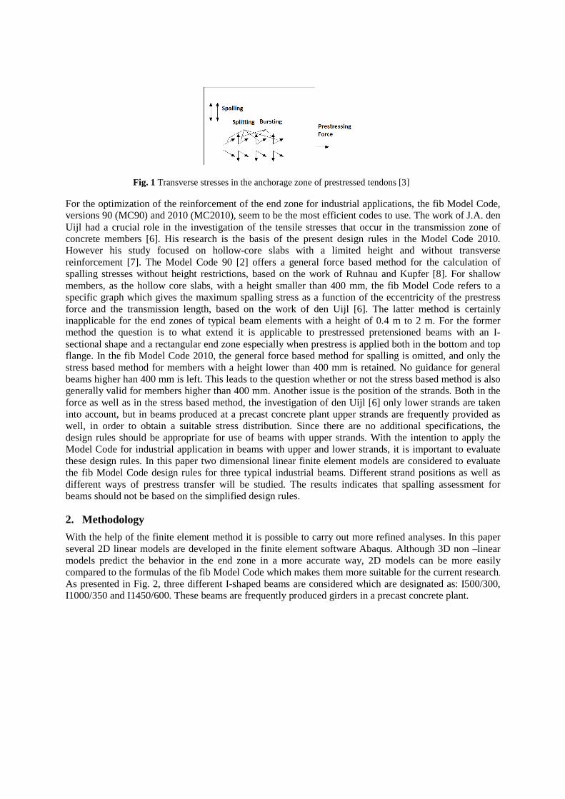
For the optimization of the reinforcement of the end zone for industrial applications, the fib Model Code, versions 90 (MC90) and 2010 (MC2010), seem to be the most efficient codes to use. The work of J.A. den Uijl had a crucial role in the investigation of the tensile stresses that occur in the transmission zone of concrete members [6]. His research is the basis of the present design rules in the Model Code 2010. However his study focused on hollow-core slabs with a limited height and without transverse reinforcement [7]. The Model Code 90 [2] offers a general force based method for the calculation of spalling stresses without height restrictions, based on the work of Ruhnau and Kupfer [8]. For shallow members, as the hollow core slabs, with a height smaller than 400 mm, the fib Model Code refers to a specific graph which gives the maximum spalling stress as a function of the eccentricity of the prestress force and the transmission length, based on the work of den Uijl [6]. The latter method is certainly inapplicable for the end zones of typical beam elements with a height of 0.4 m to 2 m. For the former method the question is to what extend it is applicable to prestressed pretensioned beams with an I-sectional shape and a rectangular end zone especially when prestress is applied both in the bottom and top flange. In the fib Model Code 2010, the general force based method for spalling is omitted, and only the stress based method for members with a height lower than 400 mm is retained. No guidance for general beams higher han 400 mm is left. This leads to the question whether or not the stress based method is also generally valid for members higher than 400 mm. Another issue is the position of the strands. Both in the force as well as in the stress based method, the investigation of den Uijl [6] only lower strands are taken into account, but in beams produced at a precast concrete plant upper strands are frequently provided as well, in order to obtain a suitable stress distribution. Since there are no additional specifications, the design rules should be appropriate for use of beams with upper strands. With the intention to apply the Model Code for industrial application in beams with upper and lower strands, it is important to evaluate these design rules. In this paper two dimensional linear finite element models are considered to evaluate the fib Model Code design rules for three typical industrial beams. Different strand positions as well as different ways of prestress transfer will be studied. The results indicates that spalling assessment for beams should not be based on the simplified design rules.
2. Methodology
With the help of the finite element method it is possible to carry out more refined analyses. In this paper several 2D linear models are developed in the finite element software Abaqus. Although 3D non –linear models predict the behavior in the end zone in a more accurate way, 2D models can be more easily compared to the formulas of the fib Model Code which makes them more suitable for the current research. As presented in Fig. 2, three different I-shaped beams are considered which are designated as: I500/300, I1000/350 and I1450/600. These beams are frequently produced girders in a precast concrete plant.
Fig. 1 Transverse stresses in the anchorage zone of prestressed tendons [3]
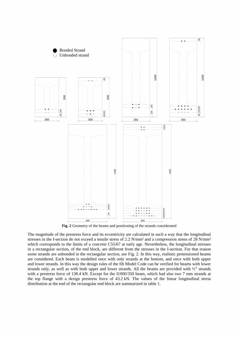
Fig. 2 Geometry of the beams and positioning of the strands considerated
The magnitude of the prestress force and its eccentricity are calculated in such a way that the longitudinal stresses in the I-section do not exceed a tensile stress of 2.2 N/mm² and a compression stress of 28 N/mm² which corresponds to the limits of a concrete C55/67 at early age. Nevertheless, the longitudinal stresses in a rectangular section, of the end block, are different from the stresses in the I-section. For that reason some strands are unbonded in the rectangular section, see Fig. 2. In this way, realistic pretensioned beams are considered. Each beam is modelled once with only strands at the bottom, and once with both upper and lower strands. In this way the design rules of the fib Model Code can be verified for beams with lower strands only, as well as with both upper and lower strands. All the beams are provided with ½” strands with a prestress force of 138.4 kN. Except for the I1000/350 beam, which had also two 7 mm strands at the top flange with a design prestress force of 43.2 kN. The values of the linear longitudinal stress distribution at the end of the rectangular end block are summarized in table 1.
300
500
6040
300
500
4040
40
350
1000
120
40
350
1000
6040
4040
600
1450
140
4040
600
1450
4040
4040
4040
Bonded Strand Unbonded strand

Table 1. Horizontal stresses at the end of the rectangular sections of the analyzed beams
Lower strands Upper and lower strands Rectangular section I500 I1000 I1450 I500 I1000 I1450 Horizontal stress at the top [N/mm²] 1.48 1.81 2.05 2.20 2.11 1.98 Horizontal stress at the bottom [N/mm²] -5.17 -5.03 -5.29 -10.73 -11.76 -9.08 Stress ratio 0.29 0.36 0.39 0.21 0.18 0.22 I-section I500 I1000 I1450 I500 I1000 I1450 Horizontal stress at the top [N/mm²] 2.22 1.99 2.16 2.13 2.03 2.06 Horizontal stress at the bottom [N/mm²] -15.89 -11.09 -13.37 -24.76 -26.30 -27.69 Stress ratio 0.14 0.18 0.16 0.09 0.08 0.07
The transfer of the prestress force is modelled in three different ways. The first way is as a concentrated force at the edge of the beam. This model can be compared with post tensioning and should overestimate the spalling and bursting stresses for pretensioned beams. The second way of modelling the prestress force is with a body force. A body force can be used to prescribe a loading per unit of volume (see Fig. 3). So to elucidate, the prestress force is placed on the volume of the strand. For example a force of 276.8 kN is uniformly distributed at the level of a strand of 12.5 mm, a transfer length (Lt) and the width of the beam of 350 mm, which results in a uniform body force of 0.18 N/mm³.
tbeamstrand .L.W φP
Fbody force =
In the third model the prestress force is modelled as a surface traction. In particular the prestress force of the strand is put as a shear traction over the surface of the strand. In the second and third model the transfer of the prestress force itself can be modelled in different ways as Fig. 4 demonstrates. The prestress transfer is modelled as a uniform, a linear or a bilinear (with the maximum at 20 % of the transfer length) transfer function [9]. Furthermore, the transfer length is a defining factor in this case and will be set at realistic values of 350 mm, 600 mm and 850 mm based on the transfer length formula of the Model Code.
Fig 3. Abaqus model, linear distributed force Fig. 4 Prestress transfer functions
The first investigated vertical stress is the spalling stress. According to MC90 this force is based on a trapezoidal linear longitudinal stress distribution in the concrete, at a horizontal position equal to the transfer length (See Fig. 5a). Along section BB (See Fig 5b), there is no acting shear force and the spalling force results from a moment equilibrium along this section [2].
Transfer length
20 %
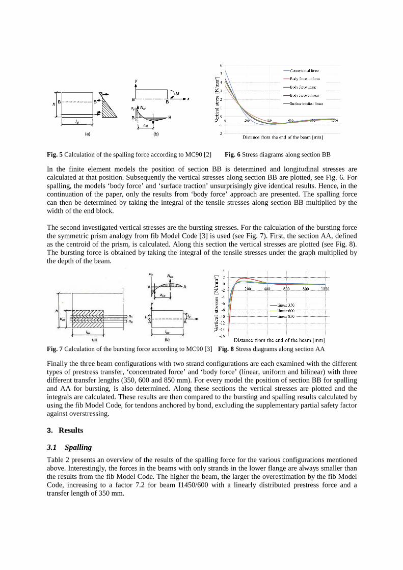
Fig. 5 Calculation of the spalling force according to MC90 [2] Fig. 6 Stress diagrams along section BB
In the finite element models the position of section BB is determined and longitudinal stresses are calculated at that position. Subsequently the vertical stresses along section BB are plotted, see Fig. 6. For spalling, the models ‘body force’ and ‘surface traction’ unsurprisingly give identical results. Hence, in the continuation of the paper, only the results from ‘body force’ approach are presented. The spalling force can then be determined by taking the integral of the tensile stresses along section BB multiplied by the width of the end block. The second investigated vertical stresses are the bursting stresses. For the calculation of the bursting force the symmetric prism analogy from fib Model Code [3] is used (see Fig. 7). First, the section AA, defined as the centroid of the prism, is calculated. Along this section the vertical stresses are plotted (see Fig. 8). The bursting force is obtained by taking the integral of the tensile stresses under the graph multiplied by the depth of the beam.
Fig. 7 Calculation of the bursting force according to MC90 [3] Fig. 8 Stress diagrams along section AA
Finally the three beam configurations with two strand configurations are each examined with the different types of prestress transfer, ‘concentrated force’ and ‘body force’ (linear, uniform and bilinear) with three different transfer lengths (350, 600 and 850 mm). For every model the position of section BB for spalling and AA for bursting, is also determined. Along these sections the vertical stresses are plotted and the integrals are calculated. These results are then compared to the bursting and spalling results calculated by using the fib Model Code, for tendons anchored by bond, excluding the supplementary partial safety factor against overstressing.
3. Results
3.1 Spalling
Table 2 presents an overview of the results of the spalling force for the various configurations mentioned above. Interestingly, the forces in the beams with only strands in the lower flange are always smaller than the results from the fib Model Code. The higher the beam, the larger the overestimation by the fib Model Code, increasing to a factor 7.2 for beam I1450/600 with a linearly distributed prestress force and a transfer length of 350 mm.
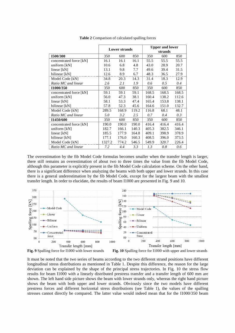
Table 2 Comparison of calculated spalling forces
Lower strands Upper and lower
strands I500/300 350 600 850 350 600 850 concentrated force [kN] 16.1 16.1 16.1 55.5 55.5 55.5 uniform [kN] 10.6 6.8 4.8 43.0 28.9 20.7 linear [kN] 13.1 9.8 7.7 49.6 39.4 31.5 bilinear [kN] 12.6 8.9 6.7 48.3 36.5 27.9 Model Code [kN] 34.8 20.3 14.3 31.4 18.3 12.9 Ratio MC and linear 2.6 2.1 1.9 0.6 0.5 0.4 I1000/350 350 600 850 350 600 850 concentrated force [kN] 59.1 59.1 59.1 168.5 168.5 168.5 uniform [kN] 56.0 47.3 38.1 160.4 138.2 112.6 linear [kN] 58.1 53.3 47.4 165.4 153.8 138.1 bilinear [kN] 57.8 52.3 45.6 164.6 151.0 132.7 Model Code [kN] 289.5 168.9 119.2 116.8 68.1 48.1 Ratio MC and linear 5.0 3.2 2.5 0.7 0.4 0.3 I1450/600 350 600 850 350 600 850 concentrated force [kN] 190.0 190.0 190.0 416.4 416.4 416.4 uniform [kN] 182.7 166.1 140.3 405.3 382.5 346.1 linear [kN] 185.5 177.9 164.8 409.1 398.9 378.9 bilinear [kN] 177.1 176.0 160.3 408.5 396.0 373.5 Model Code [kN] 1327.2 774.2 546.5 549.9 320.7 226.4 Ratio MC and linear 7.2 4.4 3.3 1.3 0.8 0.6
The overestimation by the fib Model Code formulas becomes smaller when the transfer length is larger, there still remains an overestimation of about two to three times the value from the fib Model Code, although this parameter is explicitly present in the fib Model Code calculation scheme. On the other hand, there is a significant difference when analyzing the beams with both upper and lower strands. In this case there is a general underestimation by the fib Model Code, except for the largest beam with the smallest transfer length. In order to elucidate, the results of beam I1000 are presented in Fig. 9 and 10.
Fig. 9 Spalling force for I1000 with lower strands Fig. 10 Spalling force for I1000 with upper and lower strands
It must be noted that the two series of beams according to the two different strand positions have different longitudinal stress distributions as mentioned in Table 1. Despite this difference, the reason for the large deviation can be explained by the shape of the principal stress trajectories. In Fig. 10 the stress flow results for beam I1000 with a linearly distributed prestress transfer and a transfer length of 600 mm are shown. The left hand side picture shows the beam with lower strands only, whereas the right hand picture shows the beam with both upper and lower strands. Obviously since the two models have different prestress forces and different horizontal stress distributions (see Table 1), the values of the spalling stresses cannot directly be compared. The latter value would indeed mean that for the I1000/350 beam
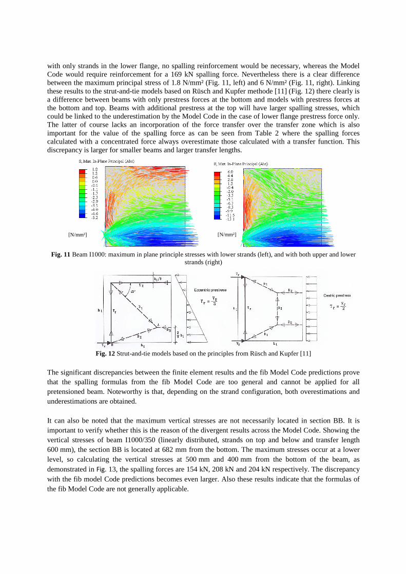
with only strands in the lower flange, no spalling reinforcement would be necessary, whereas the Model Code would require reinforcement for a 169 kN spalling force. Nevertheless there is a clear difference between the maximum principal stress of 1.8 N/mm² (Fig. 11, left) and 6 N/mm² (Fig. 11, right). Linking these results to the strut-and-tie models based on Rüsch and Kupfer methode [11] (Fig. 12) there clearly is a difference between beams with only prestress forces at the bottom and models with prestress forces at the bottom and top. Beams with additional prestress at the top will have larger spalling stresses, which could be linked to the underestimation by the Model Code in the case of lower flange prestress force only. The latter of course lacks an incorporation of the force transfer over the transfer zone which is also important for the value of the spalling force as can be seen from Table 2 where the spalling forces calculated with a concentrated force always overestimate those calculated with a transfer function. This discrepancy is larger for smaller beams and larger transfer lengths.
Fig. 11 Beam I1000: maximum in plane principle stresses with lower strands (left), and with both upper and lower
strands (right)
Fig. 12 Strut-and-tie models based on the principles from Rüsch and Kupfer [11]
The significant discrepancies between the finite element results and the fib Model Code predictions prove that the spalling formulas from the fib Model Code are too general and cannot be applied for all pretensioned beam. Noteworthy is that, depending on the strand configuration, both overestimations and underestimations are obtained. It can also be noted that the maximum vertical stresses are not necessarily located in section BB. It is important to verify whether this is the reason of the divergent results across the Model Code. Showing the vertical stresses of beam I1000/350 (linearly distributed, strands on top and below and transfer length 600 mm), the section BB is located at 682 mm from the bottom. The maximum stresses occur at a lower level, so calculating the vertical stresses at 500 mm and 400 mm from the bottom of the beam, as demonstrated in Fig. 13, the spalling forces are 154 kN, 208 kN and 204 kN respectively. The discrepancy with the fib model Code predictions becomes even larger. Also these results indicate that the formulas of the fib Model Code are not generally applicable.
[N/mm²] [N/mm²]
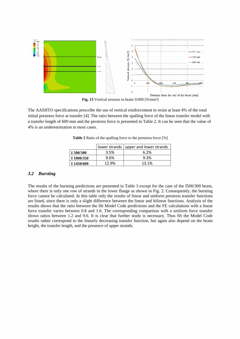
Fig. 13 Vertical stresses in beam I1000 [N/mm²]
The AASHTO specifications prescribe the use of vertical reinforcement to resist at least 4% of the total initial prestress force at transfer [4]. The ratio between the spalling force of the linear transfer model with a transfer length of 600 mm and the prestress force is presented in Table 2. It can be seen that the value of 4% is an underestimation in most cases.
Table 2 Ratio of the spalling force to the prestress force [%]
lower strands upper and lower strands
I 500/300 3.5% 6.2%
I 1000/350 9.6% 9.3%
I 1450/600 12.9% 13.1%
3.2 Bursting
The results of the bursting predictions are presented in Table 3 except for the case of the I500/300 beam, where there is only one row of strands in the lower flange as shown in Fig. 2. Consequently, the bursting force cannot be calculated. In this table only the results of linear and uniform prestress transfer functions are listed, since there is only a slight difference between the linear and bilinear functions. Analysis of the results shows that the ratio between the fib Model Code predictions and the FE calculations with a linear force transfer varies between 0.8 and 1.6. The corresponding comparison with a uniform force transfer shows ratios between 1.2 and 9.6. It is clear that further study is necessary. Thus fib the Model Code results rather correspond to the linearly decreasing transfer function, but again also depend on the beam height, the transfer length, and the presence of upper strands.
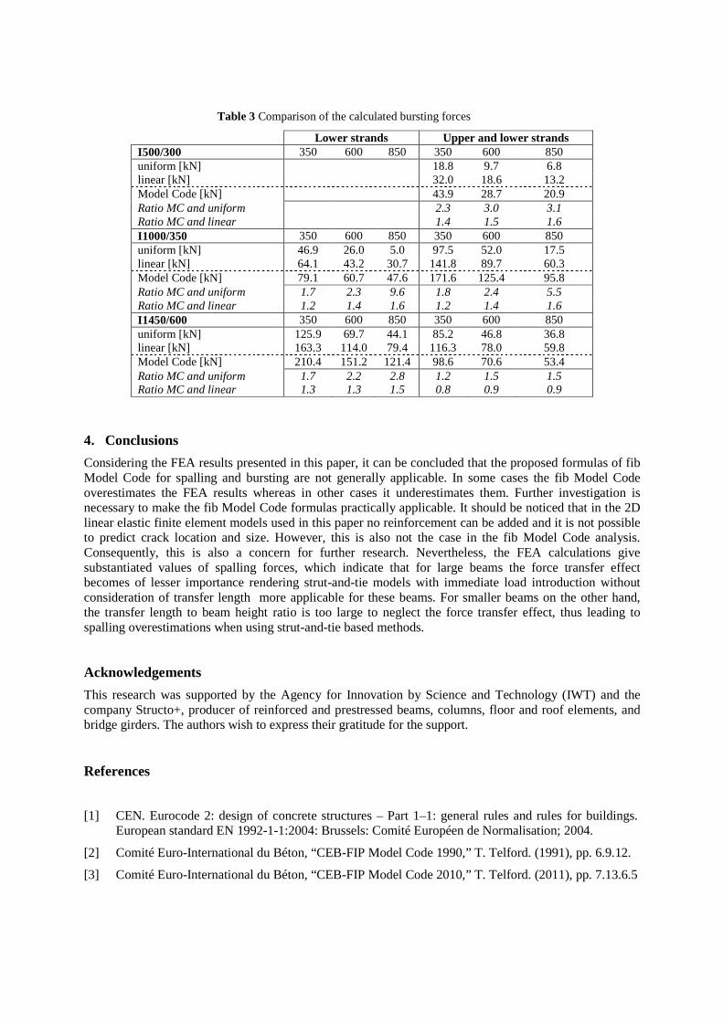
Table 3 Comparison of the calculated bursting forces
Lower strands Upper and lower strands I500/300 350 600 850 350 600 850 uniform [kN] 18.8 9.7 6.8 linear [kN]
32.0 18.6 13.2
Model Code [kN] 43.9 28.7 20.9 Ratio MC and uniform 2.3 3.0 3.1 Ratio MC and linear 1.4 1.5 1.6 I1000/350 350 600 850 350 600 850 uniform [kN] 46.9 26.0 5.0 97.5 52.0 17.5 linear [kN] 64.1 43.2 30.7 141.8 89.7 60.3 Model Code [kN] 79.1 60.7 47.6 171.6 125.4 95.8 Ratio MC and uniform 1.7 2.3 9.6 1.8 2.4 5.5 Ratio MC and linear 1.2 1.4 1.6 1.2 1.4 1.6 I1450/600 350 600 850 350 600 850 uniform [kN] 125.9 69.7 44.1 85.2 46.8 36.8 linear [kN] 163.3 114.0 79.4 116.3 78.0 59.8 Model Code [kN] 210.4 151.2 121.4 98.6 70.6 53.4 Ratio MC and uniform 1.7 2.2 2.8 1.2 1.5 1.5 Ratio MC and linear 1.3 1.3 1.5 0.8 0.9 0.9
4. Conclusions
Considering the FEA results presented in this paper, it can be concluded that the proposed formulas of fib Model Code for spalling and bursting are not generally applicable. In some cases the fib Model Code overestimates the FEA results whereas in other cases it underestimates them. Further investigation is necessary to make the fib Model Code formulas practically applicable. It should be noticed that in the 2D linear elastic finite element models used in this paper no reinforcement can be added and it is not possible to predict crack location and size. However, this is also not the case in the fib Model Code analysis. Consequently, this is also a concern for further research. Nevertheless, the FEA calculations give substantiated values of spalling forces, which indicate that for large beams the force transfer effect becomes of lesser importance rendering strut-and-tie models with immediate load introduction without consideration of transfer length more applicable for these beams. For smaller beams on the other hand, the transfer length to beam height ratio is too large to neglect the force transfer effect, thus leading to spalling overestimations when using strut-and-tie based methods.
Acknowledgements
This research was supported by the Agency for Innovation by Science and Technology (IWT) and the company Structo+, producer of reinforced and prestressed beams, columns, floor and roof elements, and bridge girders. The authors wish to express their gratitude for the support.
References
[1] CEN. Eurocode 2: design of concrete structures – Part 1–1: general rules and rules for buildings. European standard EN 1992-1-1:2004: Brussels: Comité Européen de Normalisation; 2004.
[2] Comité Euro-International du Béton, “CEB-FIP Model Code 1990,” T. Telford. (1991), pp. 6.9.12.
[3] Comité Euro-International du Béton, “CEB-FIP Model Code 2010,” T. Telford. (2011), pp. 7.13.6.5
[4] American Association of State Highway and Transportation Officials, AASHTO LRFD 2012 Bridge Design Specifications, (6), (2012), pp. 5-144 - 5-145.
[5] American Concrete Institute, “Building code requirements for reinforced concrete (ACI 318-11)”. ACI Committee 318, 2011, Michigan.
[6] den Uijl, J.A. (1983). “Tensile stresses in the transmission zones of hollow-core slabs prestressed with pretensioned strands (report 5-83-10)”. Steven Laboratorium, Delft University of Technology
[7] den Uijl, J.A. (1985). “Bond properties of strands in connection with transmission zone cracks”. Betonwerk 1/1985, p28-39. Steven Laboratorium, Delft University of Technology
[8] Ruhnau and Kupfer (1977). “Spaltzug-, Stirnzug- und Schubbewehrung im Eintragungsbereich von Spanbett-Trägern”. Beton und Stahlbetonbau 7/1977.
[9] Balázs,G.L. (1993). “Transfer Length of Prestressing Strand as a Function of Draw-In and Initial Prestress”. PCI Journal, (1993), pp. 86-93.
[10] FIP report on prestressing steel, “2. Anchorage and application of pretensioned 7-wire strands”, Fédération Internationale de la Précontrainte, 1978
[11] Schlaich, J. (1987). “Toward a concistent Design of Structural Concrete”. PCI Journal, Vol.32, p74-150.

![VERIFICATION OF THE BURSTING AND SPALLING FORMULAS IN … · Various codes as Eurocode 2 [1], fib Model Code [2,3], ASHTOO [4] and ACI [5] provide guidelines for the calculation of](https://img.pdfslide.net/doc/110x75/61350d35dfd10f4dd73c1fc8/verification-of-the-bursting-and-spalling-formulas-in-various-codes-as-eurocode.jpg)