Embed Size (px)
Citation preview
Verilog Reference Manual http://eesun.free.fr/DOC/VERILOG/verilog_manual1.html
1 of 37 10/31/2007 7:51 PM
Verilog Reference Manual
Preface:
This is a brief summary of the syntax and semantics of the Verilog Hardware description Language. The summary is not intended at being an exhaustive
list of all the constructs and is not meant to be complete. This reference guide also lists constructs that can be synthesized. For any clarifications and to
resolve ambiguities, please refer to the Verilog Reference Manual Copyright 1993 by Open Verilog International Inc. and synthesis vendors Verilog
HDL Reference Manuals.
Note: this document will be constantly updated with new verilog design examples and useful tricks. A last modified date will be placed at the beginning
of the file.
Last modified 14/04/97
Quick Reference for Verilog HDL
1.0 Lexical Element
1.1 Integer Literals
1.2 Data Types
2.0 Registers and Nets
3.0 Compiler Directives
4.0 System Tasks and Functions
5.0 Reserved Keywords
6.0 Structures and Hierarchy
6.1 Module Declarations
6.2 UDP Declarations
7.0 Expressions and Operators
Verilog Reference Manual http://eesun.free.fr/DOC/VERILOG/verilog_manual1.html
2 of 37 10/31/2007 7:51 PM
7.1 Parallel Expressions
7.2 Conditional Statements
7.3 Looping Statements
8.0 Named Blocks, Disabled Blocks
9.0 Tasks and Functions
10.0 Continuous Assignments
11.0 Procedural Assignments
11.1 Blocking Assignment
11.2 Non- blocking Assignment
12.0 Gate Types, MOS and bidirectional switches
12.1 Gate Delays
13.0 Specify Blocks
14.0 Verilog Synthesis Constructs
14.1 Fully Supported Constructs
14.2 Partially Supported Constructs
14.3 Ignored Constructs
14.4 Unsupported Constructs
15.0 Index
16.0 Synopsys Methodology Note: Verilog RTL descriptions
17.0 Synopsys Methodology Note: ASIC Partitioning
Use and Copyright
Verilog Reference Manual http://eesun.free.fr/DOC/VERILOG/verilog_manual1.html
3 of 37 10/31/2007 7:51 PM
Copyright (c) 1994, 1995 Rajeev Madhavan
Copyright (c) 1994, 1995 Automata Publishing Company
Permission to use, copy and distribute this book for any purpose is hereby granted without fee provided that
(i) the above copyright notices and this permission notice appears in all copies and
(ii)
the name of Rajeev Madhavan, Automata Publishing and AMBIT Design Systems may not be used in any advertising or publicity relating to this book
without the specific prior permission of Rajeev Madhavan, Automata Publishing and AMBIT Design Systems.
1.0 Lexical Elements
The language is case sensitive and all the keywords are lower case. White space, namely spaces, tabs and new-lines are ignored Verilog has two types of
comments:
1. One Line comments start with // and end at the end of the line
2. Multi line comments start with /* and end with */
Variable names have to start with an alphanumeric character or underscore followed by alohanumeric or underscore characters. The only exception to
this are the system tasks and functionswhich start with a dollar sign. Escaped Identifiers (identifier whose first character is a backslash (\))permit non
alphanumeric characters in Verilog name. The escaped name includes all the characters following the backslash until the first whitespace character.
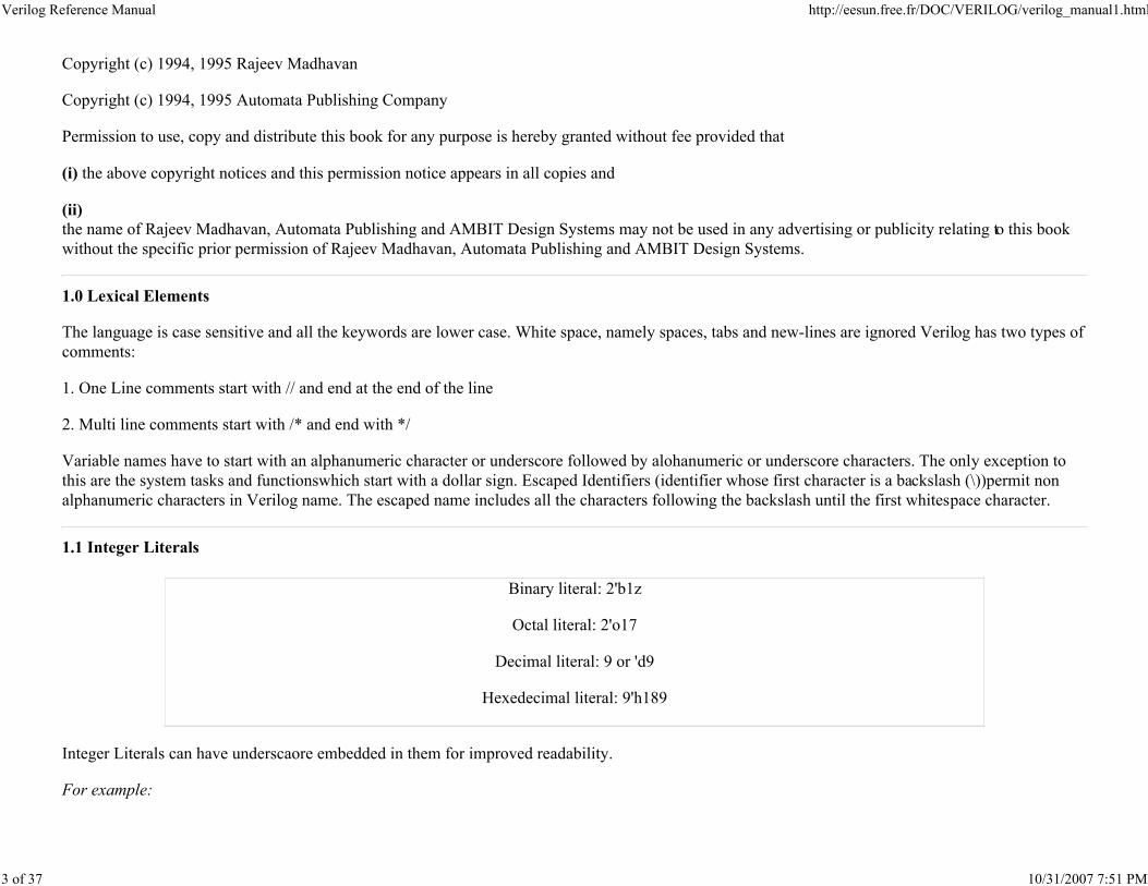
1.1 Integer Literals
Binary literal: 2'b1z
Octal literal: 2'o17
Decimal literal: 9 or 'd9
Hexedecimal literal: 9'h189
Integer Literals can have underscaore embedded in them for improved readability.
For example:
Verilog Reference Manual http://eesun.free.fr/DOC/VERILOG/verilog_manual1.html
4 of 37 10/31/2007 7:51 PM
Decimal Literal 24_000
1.2 Data Types
The values z and Z stand for high impedance and x and X stand for uninitialised variables or nets with conflicting drivers. String symbols are enclosed
with double quotes ("string") and cannot span multiple lines. Real number literals can be either in fixed notation or in scientific notation.
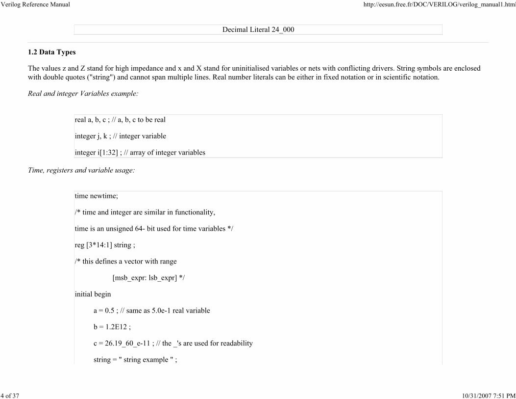
Real and integer Variables example:
real a, b, c ; // a, b, c to be real
integer j, k ; // integer variable
integer i[1:32] ; // array of integer variables
Time, registers and variable usage:
time newtime;
/* time and integer are similar in functionality,
time is an unsigned 64- bit used for time variables */
reg [3*14:1] string ;
/* this defines a vector with range
[msb_expr: lsb_expr] */
initial begin
a = 0.5 ; // same as 5.0e-1 real variable
b = 1.2E12 ;
c = 26.19_60_e-11 ; // the _'s are used for readability
string = " string example " ;
Verilog Reference Manual http://eesun.free.fr/DOC/VERILOG/verilog_manual1.html
5 of 37 10/31/2007 7:51 PM
newtime = $time ;
end
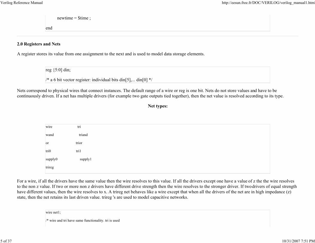
2.0 Registers and Nets
A register stores its value from one assignment to the next and is used to model data storage elements.
reg {5:0] din;
/* a 6 bit vector register: individual bits din[5],... din[0] */
Nets correspond to physical wires that connect instances. The default range of a wire or reg is one bit. Nets do not store values and have to be
continuously driven. If a net has multiple drivers (for example two gate outputs tied together), then the net value is resolved according to its type.
Net types:
wire tri
wand triand
or trior
tri0 tri1
supply0 supply1
trireg
For a wire, if all the drivers have the same value then the wire resolves to this value. If all the drivers except one have a value of z the the wire resolves
to the non z value. If two or more non z drivers have different drive strength then the wire resolves to the stronger driver. If two drivers of equal strength
have different values, then the wire resolves to x. A trireg net behaves like a wire except that when all the drivers of the net are in high impedance (z)
state, then the net retains its last driven value. trireg 's are used to model capacitive networks.
wire net1;
/* wire and tri have same functionality. tri is used
Verilog Reference Manual http://eesun.free.fr/DOC/VERILOG/verilog_manual1.html
6 of 37 10/31/2007 7:51 PM
for multiple drive internal wire */
trireg (medium) capacitor ;
/* small medium and weak are used for charge strength modelling */
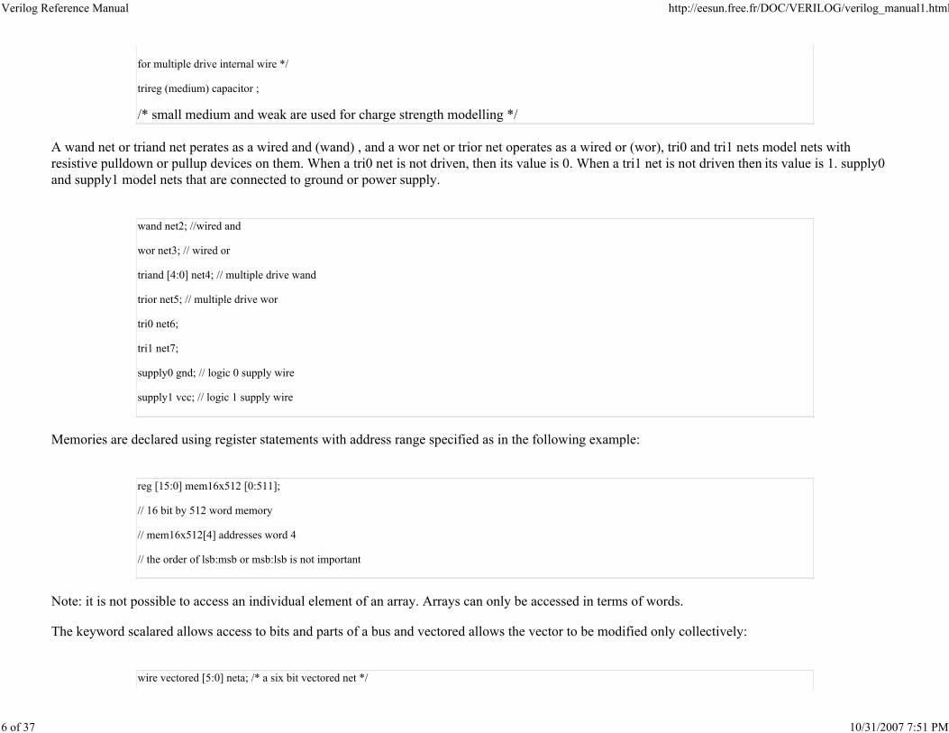
A wand net or triand net perates as a wired and (wand) , and a wor net or trior net operates as a wired or (wor), tri0 and tri1 nets model nets with
resistive pulldown or pullup devices on them. When a tri0 net is not driven, then its value is 0. When a tri1 net is not driven then its value is 1. supply0
and supply1 model nets that are connected to ground or power supply.
wand net2; //wired and
wor net3; // wired or
triand [4:0] net4; // multiple drive wand
trior net5; // multiple drive wor
tri0 net6;
tri1 net7;
supply0 gnd; // logic 0 supply wire
supply1 vcc; // logic 1 supply wire
Memories are declared using register statements with address range specified as in the following example:
reg [15:0] mem16x512 [0:511];
// 16 bit by 512 word memory
// mem16x512[4] addresses word 4
// the order of lsb:msb or msb:lsb is not important
Note: it is not possible to access an individual element of an array. Arrays can only be accessed in terms of words.
The keyword scalared allows access to bits and parts of a bus and vectored allows the vector to be modified only collectively:
wire vectored [5:0] neta; /* a six bit vectored net */
Verilog Reference Manual http://eesun.free.fr/DOC/VERILOG/verilog_manual1.html
7 of 37 10/31/2007 7:51 PM
tri1 vectored [5:0] netb; /* a six bit vectored tri1
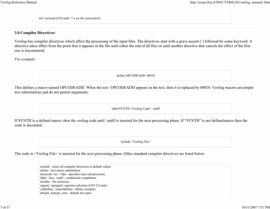
3.0 Compiler Directives:
Verilog has compiler directives which affect the processing of the input files. The directives start with a grave accent (`) followed by some keyword. A
directive takes effect from the point that it appears in the file until either the end of all files or until another directive that cancels the effect of the first
one is encountered.
For example:
`define OPCODEADD 00010
This defines a macro named OPCODEADD. When the text `OPCODEADD appears in the text, then it is replaced by 00010. Verilog macros are simple
text substitutions and do not permit arguments.
`ifdef SYNTH <Verilog Code> `endif
If SYNTH is a defined macro, then the verilog code until `endif is inserted for the next processing phase. If “SYNTH” is not defined macro then the
code is discarded.
`include <Verilog File>
The code in <Verilog File> is inserted for the next processing phase. Other standard compiler directives are listed below.
`resetall - resets all compiler directives to default values
`define - text macro substitution
`timescale 1ns / 10ps - specifies time unit/precision
`ifdef, `else, `endif - conditional compilation
`include - file inclusion
`signed, `unsigned -operator selection (OVI 2.0 only)
`celldefine, `endcelldefine - library modules
`default_nettype_wire - default net types
Verilog Reference Manual http://eesun.free.fr/DOC/VERILOG/verilog_manual1.html
8 of 37 10/31/2007 7:51 PM
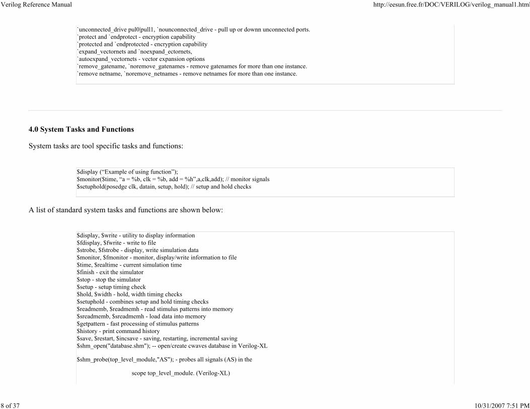
`unconnected_drive pul0|pull1, `nounconnected_drive - pull up or downn unconnected ports.
`protect and `endprotect - encryption capability
`protected and `endprotected - encryption capability
`expand_vectornets and `noexpand_ectornets,
`autoexpand_vectornets - vector expansion options
`remove_gatename, `noremove_gatenames - remove gatenames for more than one instance.
`remove netname, `noremove_netnames - remove netnames for more than one instance.
4.0 System Tasks and Functions
System tasks are tool specific tasks and functions:
$display (“Example of using function”);
$monitor($time, “a = %b, clk = %b, add = %h”,a,clk,add); // monitor signals
$setuphold(posedge clk, datain, setup, hold); // setup and hold checks
A list of standard system tasks and functions are shown below:
$display, $write - utility to display information
$fdisplay, $fwrite - write to file
$strobe, $fstrobe - display, write simulation data
$monitor, $fmonitor - monitor, display/write information to file
$time, $realtime - current simulation time
$finish - exit the simulator
$stop - stop the simulator
$setup - setup timing check
$hold, $width - hold, width timing checks
$setuphold - combines setup and hold timing checks
$readmemb, $readmemh - read stimulus patterns into memory
$sreadmemb, $sreadmemh - load data into memory
$getpattern - fast processing of stimulus patterns
$history - print command history
$save, $restart, $incsave - saving, restarting, incremental saving
$shm_open("database.shm"); -- open/create cwaves database in Verilog-XL
$shm_probe(top_level_module,"AS"); - probes all signals (AS) in the
scope top_level_module. (Verilog-XL)
Verilog Reference Manual http://eesun.free.fr/DOC/VERILOG/verilog_manual1.html
9 of 37 10/31/2007 7:51 PM
$shm_close(); - will close all open shm databases in Verilog-XL
$scale - scaling timeunits from another module
$showscopes - complete list of named blocks, tasks,modules...
$showvars - show variables at scope.
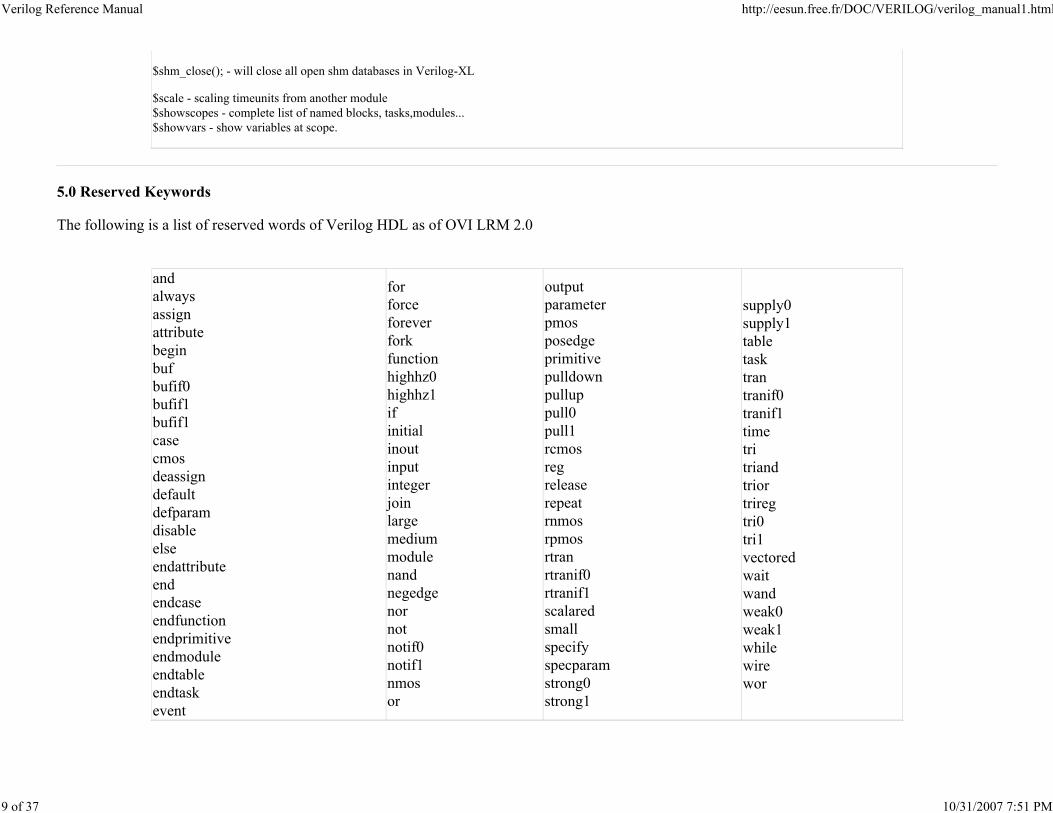
5.0 Reserved Keywords
The following is a list of reserved words of Verilog HDL as of OVI LRM 2.0
and
always
assign
attribute
begin
buf
bufif0
bufif1
bufif1
case
cmos
deassign
default
defparam
disable
else
endattribute
end
endcase
endfunction
endprimitive
endmodule
endtable
endtask
event
for
force
forever
fork
function
highhz0
highhz1
if
initial
inout
input
integer
join
large
medium
module
nand
negedge
nor
not
notif0
notif1
nmos
or
output
parameter
pmos
posedge
primitive
pulldown
pullup
pull0
pull1
rcmos
reg
release
repeat
rnmos
rpmos
rtran
rtranif0
rtranif1
scalared
small
specify
specparam
strong0
strong1
supply0
supply1
table
task
tran
tranif0
tranif1
time
tri
triand
trior
trireg
tri0
tri1
vectored
wait
wand
weak0
weak1
while
wire
wor
Verilog Reference Manual http://eesun.free.fr/DOC/VERILOG/verilog_manual1.html
10 of 37 10/31/2007 7:51 PM
6.0 Structures and Hierarchy
Hierarchical HDL structures are achieved by defining modules and instanciating modules. Nested module definitions (i.e. one module definition within
another) are not permitted.
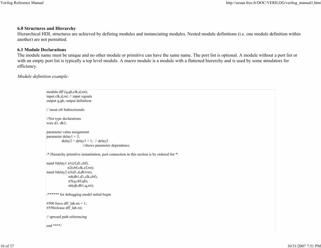
6.1 Module Declarations
The module name must be unique and no other module or primitive can have the same name. The port list is optional. A module without a port list or
with an empty port list is typically a top level module. A macro module is a module with a flattened hiererchy and is used by some simulators for
efficiency.
Module definition example:
module dff (q,qb,clk,d,rst);
input clk,d,rst; // input signals
output q,qb; output definition
// inout ofr bidirectionals
//Net type declarations
wire d1, db1;
parameter value assignment
parameter delay1 = 3,
delay2 = delay1 + 1; // delay2
//shows parameter dependence.
/* Hierarchy primitive instantiation, port connection in this section is by ordered list */
nand #delay1 n1(cf,d1,cbf),
n2(cbf,clk,cf,rst);
nand #delay2 n3(d1,d,db1rst),
n4(db1,d1,clk,cbf),
n5(q,cbf,qb),
n6(qb,db1,q,rst);
/****** for debugging model initial begin
#500 force dff_lab.rst = 1;
#550release dff_lab.rst;
// upward path referencing
end ****/
Verilog Reference Manual http://eesun.free.fr/DOC/VERILOG/verilog_manual1.html
11 of 37 10/31/2007 7:51 PM
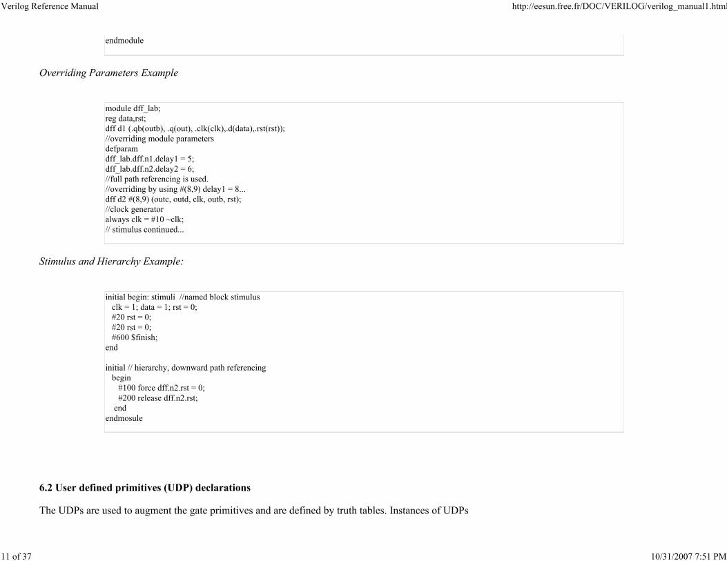
endmodule
Overriding Parameters Example
module dff_lab;
reg data,rst;
dff d1 (.qb(outb), .q(out), .clk(clk),.d(data),.rst(rst));
//overriding module parameters
defparam
dff_lab.dff.n1.delay1 = 5;
dff_lab.dff.n2.delay2 = 6;
//full path referencing is used.
//overriding by using #(8,9) delay1 = 8...
dff d2 #(8,9) (outc, outd, clk, outb, rst);
//clock generator
always clk = #10 ~clk;
// stimulus continued...
Stimulus and Hierarchy Example:
initial begin: stimuli //named block stimulus
clk = 1; data = 1; rst = 0;
#20 rst = 0;
#20 rst = 0;
#600 $finish;
end
initial // hierarchy, downward path referencing
begin
#100 force dff.n2.rst = 0;
#200 release dff.n2.rst;
end
endmosule
6.2 User defined primitives (UDP) declarations
The UDPs are used to augment the gate primitives and are defined by truth tables. Instances of UDPs
Verilog Reference Manual http://eesun.free.fr/DOC/VERILOG/verilog_manual1.html
12 of 37 10/31/2007 7:51 PM
can be used in the smae way as gate primitives. There are two types of primitives:
1. Sequential UDPs permit initialisation of output terminals which are declared to be of reg type
and they store values. Level sensitive entries take precedence over edge sensitive declarations. An input
logic state z is interpreted as an x. Similarly only 0, 1, x or - (unchanged) logic values are permitted on
the output.
2. Combinational UDPs do not store values and cannot be initialised. The following additional
abbreviations are permitted in UDP declarations:
Logic/State Representation/transition Abbreviation
don’t care (0, 1 or X) ?
Transitions from logic x to logic y (xy)
(01), (10), (0x), (1x), (x1), (x0), (?1) ..(xy)
Transition from (01) R or r
Transition from (10) F or f
(01), (0X), (X1): positive transition P or p
(10), (1x), (x0): negative transition N or n
Any transition * or (??)
binary don’t care (0,1) B or b
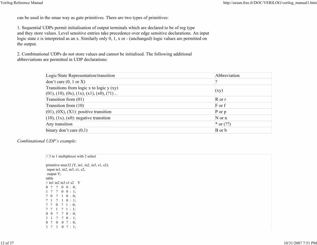
Combinational UDP’s example:
// 3 to 1 multiplexor with 2 select
primitive mux32 (Y, in1, in2, in3, s1, s2);
input in1, in2, in3, s1, s2;
output Y;
table
// in1 in2 in3 s1 s2 Y
0 ? ? 0 0 : 0;
1 ? ? 0 0 : 1;
? 0 ? 1 0 : 0;
? 1 ? 1 0 : 1;
? ? 0 ? 1 : 0;
? ? 1 ? 1 : 1;
0 0 ? ? 0 : 0;
1 1 ? ? 0 : 1;
0 ? 0 0 ? : 0;
1 ? 1 0 ? : 1;
Verilog Reference Manual http://eesun.free.fr/DOC/VERILOG/verilog_manual1.html
13 of 37 10/31/2007 7:51 PM
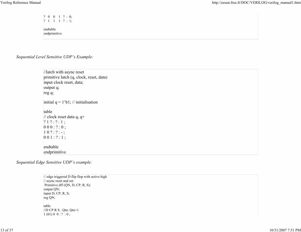
? 0 0 1 ? : 0;
? 1 1 1 ? : 1;
endtable
endprimitive
Sequential Level Sensitive UDP’s Example:
//latch with async reset
primitive latch (q, clock, reset, data)
input clock reset, data;
output q;
reg q;
initial q = 1’b1; // initialisation
table
// clock reset data q, q+
? 1 ? : ? : 1 ;
0 0 0 : ? : 0 ;
1 0 ? : ? : - ;
0 0 1 : ? : 1 ;
endtable
endprimitive
Sequential Edge Sensitive UDP’s example:
// edge triggered D flip flop with active high
// async reset and set.
Primitive dff (QN, D, CP, R, S);
output QN;
input D, CP, R, S;
reg QN;
table
//D CP R S : Qtn: Qtn+1
1 (01) 0 0 : ? : 0 ;
Verilog Reference Manual http://eesun.free.fr/DOC/VERILOG/verilog_manual1.html
14 of 37 10/31/2007 7:51 PM
1 (01) 0 x : ? : 0 ;
? ? 0 x : 0 : 0 ;
0 (01) 0 0 : ? : 1 ; // clocked data
0 (01) x 0 : ? : 1 ; // pessimism
? ? x 0 : 1 : 1 ; // pessemism
1 (x1) 0 0 : 0 : 0 ;
0 (x1) 0 0 : 1 : 1 ;
1 (0x) 0 0 : 0 : 0 ;
0 (0x) 0 0 : 1 : 1 ;
? ? 1 ? : ? : 1 ; // async clear
? ? 0 1 : ? : 0 ; // async set
? n 0 0 : ? : - ;
* ? ? ? : ? : - ;
? ? (?0)? : ? : - ;
? ? ?(?0): ? : - ;
? ? ? ? : ? : x ;
endtable
endprimitive
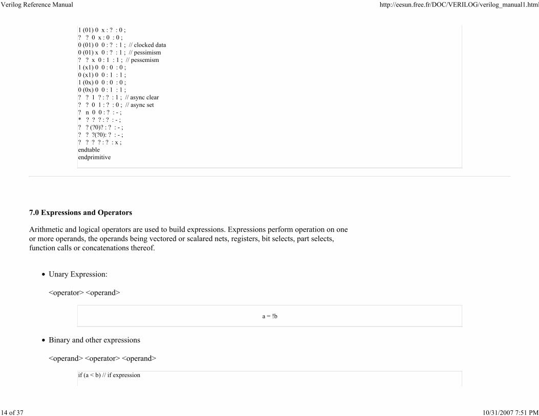
7.0 Expressions and Operators
Arithmetic and logical operators are used to build expressions. Expressions perform operation on one
or more operands, the operands being vectored or scalared nets, registers, bit selects, part selects,
function calls or concatenations thereof.
Unary Expression:
<operator> <operand>
a = !b
Binary and other expressions
<operand> <operator> <operand>
if (a < b) // if expression
Verilog Reference Manual http://eesun.free.fr/DOC/VERILOG/verilog_manual1.html
15 of 37 10/31/2007 7:51 PM
{c,d} = a + b;
/ concatenate and add operator
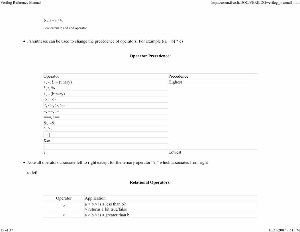
Parentheses can be used to change the precedence of operators. For example ((a + b) * c)
Operator Precedence:
Operator Precedence
+, -, !, ~ (unary) Highest
*, /, %
+, - (binary)
<<, >>
<, <=, >, >=
=, ==, !=
===, !==
&, ~&
^, ^~
|, ~|
&&
||
?: Lowest
Note all operators associate left to right except for the ternary operator “?:” which associates from right
to left.
Relational Operators:
Operator Application
<a < b // is a less than b?
// returns 1 bit true/false
> a > b // is a greater than b
Verilog Reference Manual http://eesun.free.fr/DOC/VERILOG/verilog_manual1.html
16 of 37 10/31/2007 7:51 PM
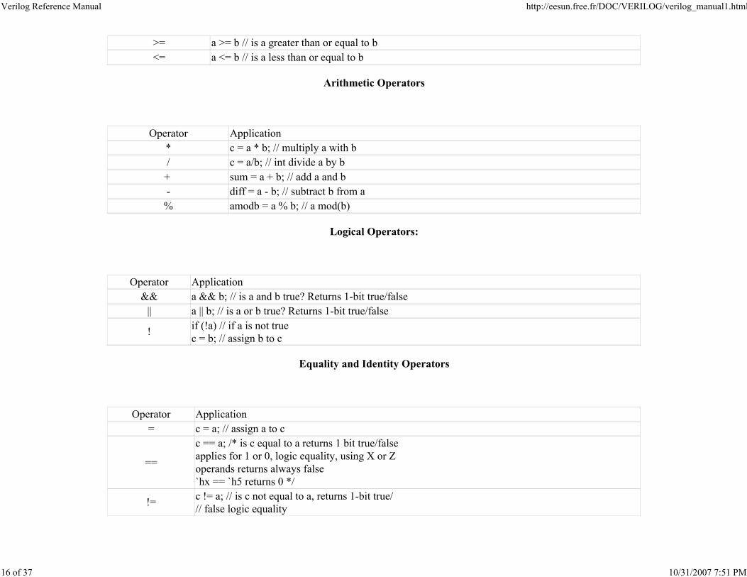
>= a >= b // is a greater than or equal to b
<= a <= b // is a less than or equal to b
Arithmetic Operators
Operator Application
* c = a * b; // multiply a with b
/ c = a/b; // int divide a by b
+ sum = a + b; // add a and b
- diff = a - b; // subtract b from a
% amodb = a % b; // a mod(b)
Logical Operators:
Operator Application
&& a && b; // is a and b true? Returns 1-bit true/false
|| a || b; // is a or b true? Returns 1-bit true/false
!if (!a) // if a is not true
c = b; // assign b to c
Equality and Identity Operators
Operator Application
= c = a; // assign a to c
==
c == a; /* is c equal to a returns 1 bit true/false
applies for 1 or 0, logic equality, using X or Z
operands returns always false
`hx == `h5 returns 0 */
!=c != a; // is c not equal to a, returns 1-bit true/
// false logic equality
Verilog Reference Manual http://eesun.free.fr/DOC/VERILOG/verilog_manual1.html
17 of 37 10/31/2007 7:51 PM
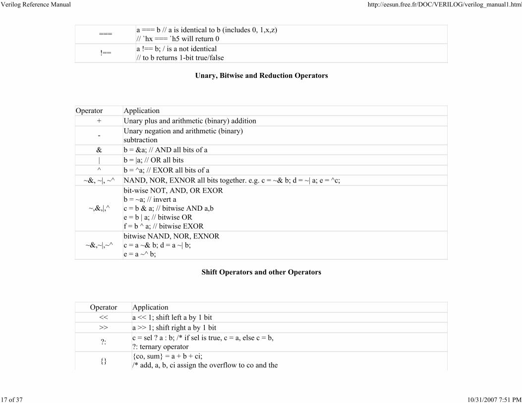
===a === b // a is identical to b (includes 0, 1,x,z)
// `hx === `h5 will return 0
!==a !== b; / is a not identical
// to b returns 1-bit true/false
Unary, Bitwise and Reduction Operators
Operator Application
+ Unary plus and arithmetic (binary) addition
-Unary negation and arithmetic (binary)
subtraction
& b = &a; // AND all bits of a
| b = |a; // OR all bits
^ b = ^a; // EXOR all bits of a
~&, ~|, ~^ NAND, NOR, EXNOR all bits together. e.g. c = ~& b; d = ~| a; e = ^c;
~,&,|,^
bit-wise NOT, AND, OR EXOR
b = ~a; // invert a
c = b & a; // bitwise AND a,b
e = b | a; // bitwise OR
f = b ^ a; // bitwise EXOR
~&,~|,~^bitwise NAND, NOR, EXNOR
c = a ~& b; d = a ~| b;
e = a ~^ b;
Shift Operators and other Operators
Operator Application
<< a << 1; shift left a by 1 bit
>> a >> 1; shift right a by 1 bit
?:c = sel ? a : b; /* if sel is true, c = a, else c = b,
?: ternary operator
{}{co, sum} = a + b + ci;
/* add, a, b, ci assign the overflow to co and the
Verilog Reference Manual http://eesun.free.fr/DOC/VERILOG/verilog_manual1.html
18 of 37 10/31/2007 7:51 PM
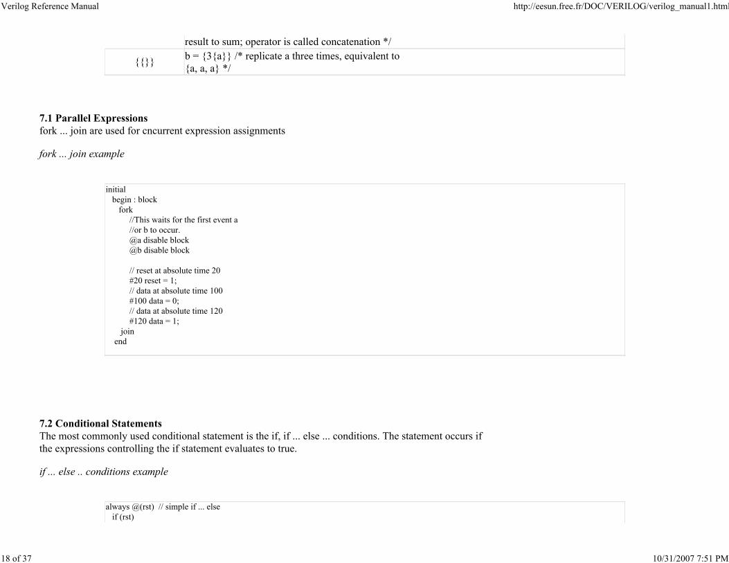
result to sum; operator is called concatenation */
{{}}b = {3{a}} /* replicate a three times, equivalent to
{a, a, a} */
7.1 Parallel Expressions
fork ... join are used for cncurrent expression assignments
fork ... join example
initial
begin : block
fork
//This waits for the first event a
//or b to occur.
@a disable block
@b disable block
// reset at absolute time 20
#20 reset = 1;
// data at absolute time 100
#100 data = 0;
// data at absolute time 120
#120 data = 1;
join
end
7.2 Conditional Statements
The most commonly used conditional statement is the if, if ... else ... conditions. The statement occurs if
the expressions controlling the if statement evaluates to true.
if ... else .. conditions example
always @(rst) // simple if ... else
if (rst)
Verilog Reference Manual http://eesun.free.fr/DOC/VERILOG/verilog_manual1.html
19 of 37 10/31/2007 7:51 PM
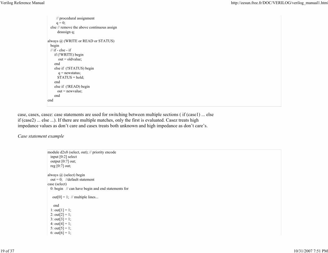
// procedural assignment
q = 0;
else // remove the above continuous assign
deassign q;
always @ (WRITE or READ or STATUS)
begin
// if - else - if
if (!WRITE) begin
out = oldvalue;
end
else if (!STATUS) begin
q = newstatus;
STATUS = hold;
end
else if (!READ) begin
out = newvalue;
end
end
case, casex, casez: case statements are used for switching between multiple sections ( if (case1) ... else
if (case2) ... else ...). If there are multiple matches, only the first is evaluated. Casez treats high
impedance values as don’t care and casex treats both unknown and high impedance as don’t care’s.
Case statement example
module d2x8 (select, out); // priority encode
input [0:2] select
output [0:7] out;
reg [0:7] out;
always @ (select) begin
out = 0; //default statement
case (select)
0: begin // can have begin and end statements for
out[0] = 1; // multiple lines...
end
1: out[1] = 1;
2: out[2] = 1;
3: out[3] = 1;
4: out[4] = 1;
5: out[5] = 1;
6: out[6] = 1;
Verilog Reference Manual http://eesun.free.fr/DOC/VERILOG/verilog_manual1.html
20 of 37 10/31/2007 7:51 PM
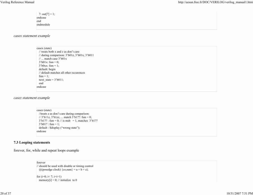
7: out[7] = 1;
endcase
end
endmodule
casex statement example
casex (state)
// treats both x and z as don’t care
// during comparison: 3’b01z, 3’b01x, 3’b011
// ... match case 3’b01x
3’b01x: fsm = 0;
3’b0xx: fsm = 1;
default: begin
// default matches all other occurences
fsm = 1;
next_state = 3’b011;
end
endcase
casez statement example
casez (state)
//treats z as don’t care during comparison:
// 3’b11z, 3’b1zz, ... match 3’b1??: fsm = 0;
3’b1?? : fsm = 0; // is msb = 1, matches 3’b1??
3’b01? : fsm = 1;
default : $display (“wrong state”);
endcase
7.3 Looping statements
forever, for, while and repeat loops example
forever
// should be used with disable or timing control
@(posedge clock) {co,sum} = a + b + ci;
for (i=0; i< 7; i=i+1)
memory[i] = 0; // initialize to 0
Verilog Reference Manual http://eesun.free.fr/DOC/VERILOG/verilog_manual1.html
21 of 37 10/31/2007 7:51 PM
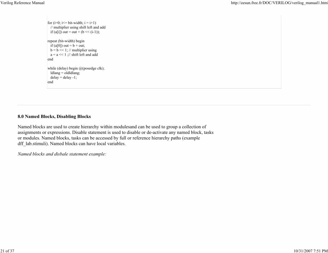
for (i=0; i<= bit-width; i = i+1)
// multiplier using shift left and add
if (a[i]) out = out + (b << (i-1));
repeat (bit-width) begin
if (a[0]) out = b + out;
b = b << 1; // multiplier using
a = a << 1 ;// shift left and add
end
while (delay) begin @(posedge clk);
ldlang = oldldlang;
delay = delay -1;
end
8.0 Named Blocks, Disabling Blocks
Named blocks are used to create hierarchy within modulesand can be used to group a collection of
assignments or expressions. Disable statement is used to disable or de-activate any named block, tasks
or modules. Named blocks, tasks can be accessed by full or reference hierarchy paths (example
dff_lab.stimuli). Named blocks can have local variables.
Named blocks and disbale statement example:
Verilog Reference Manual http://eesun.free.fr/DOC/VERILOG/verilog_manual1.html
22 of 37 10/31/2007 7:51 PM
initial forever @(posedge reset)
disable MAIN; // disable named block
// tasks and modules can also be disabled.
always begin: MAIN // defining named blocks
if (!qfull) begin
#30 recv(new,newdata); // call task
if (new) begin
q[head] = newdata;
head = head + 1; // queue
end
end
else
disable recv;
end // MAIN
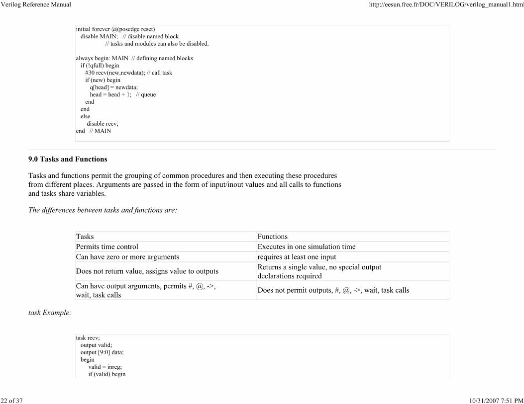
9.0 Tasks and Functions
Tasks and functions permit the grouping of common procedures and then executing these procedures
from different places. Arguments are passed in the form of input/inout values and all calls to functions
and tasks share variables.
The differences between tasks and functions are:
Tasks Functions
Permits time control Executes in one simulation time
Can have zero or more arguments requires at least one input
Does not return value, assigns value to outputsReturns a single value, no special output
declarations required
Can have output arguments, permits #, @, ->,
wait, task callsDoes not permit outputs, #, @, ->, wait, task calls
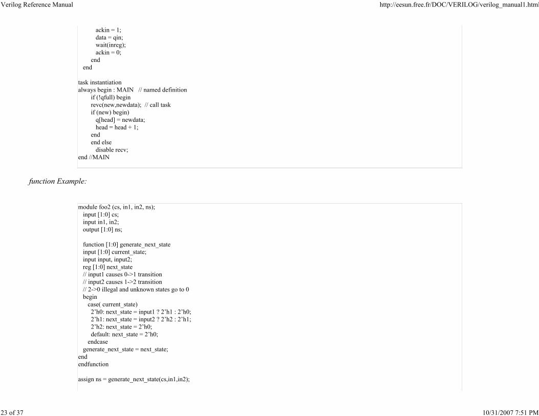
task Example:
task recv;
output valid;
output [9:0] data;
begin
valid = inreg;
if (valid) begin
Verilog Reference Manual http://eesun.free.fr/DOC/VERILOG/verilog_manual1.html
23 of 37 10/31/2007 7:51 PM
ackin = 1;
data = qin;
wait(inreg);
ackin = 0;
end
end
task instantiation
always begin : MAIN // named definition
if (!qfull) begin
revc(new,newdata); // call task
if (new) begin)
q[head] = newdata;
head = head + 1;
end
end else
disable recv;
end //MAIN
function Example:
module foo2 (cs, in1, in2, ns);
input [1:0] cs;
input in1, in2;
output [1:0] ns;
function [1:0] generate_next_state
input [1:0] current_state;
input input, input2;
reg [1:0] next_state
// input1 causes 0->1 transition
// input2 causes 1->2 transition
// 2->0 illegal and unknown states go to 0
begin
case( current_state)
2’h0: next_state = input1 ? 2’h1 : 2’h0;
2’h1: next_state = input2 ? 2’h2 : 2’h1;
2’h2: next_state = 2’h0;
default: next_state = 2’h0;
endcase
generate_next_state = next_state;
end
endfunction
assign ns = generate_next_state(cs,in1,in2);
Verilog Reference Manual http://eesun.free.fr/DOC/VERILOG/verilog_manual1.html
24 of 37 10/31/2007 7:51 PM
endmodule
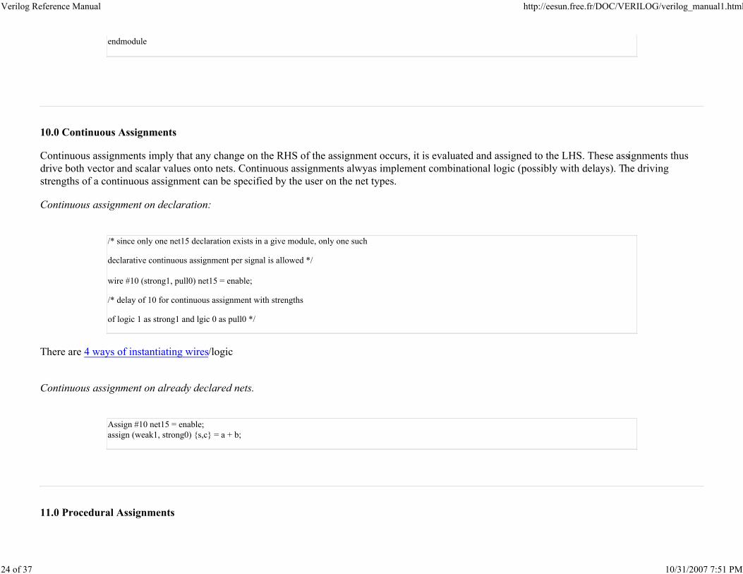
10.0 Continuous Assignments
Continuous assignments imply that any change on the RHS of the assignment occurs, it is evaluated and assigned to the LHS. These assignments thus
drive both vector and scalar values onto nets. Continuous assignments alwyas implement combinational logic (possibly with delays). The driving
strengths of a continuous assignment can be specified by the user on the net types.
Continuous assignment on declaration:
/* since only one net15 declaration exists in a give module, only one such
declarative continuous assignment per signal is allowed */
wire #10 (strong1, pull0) net15 = enable;
/* delay of 10 for continuous assignment with strengths
of logic 1 as strong1 and lgic 0 as pull0 */
There are 4 ways of instantiating wires/logic
Continuous assignment on already declared nets.
Assign #10 net15 = enable;
assign (weak1, strong0) {s,c} = a + b;
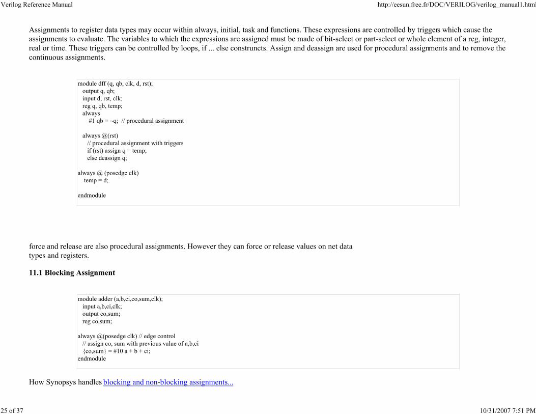
11.0 Procedural Assignments
Verilog Reference Manual http://eesun.free.fr/DOC/VERILOG/verilog_manual1.html
25 of 37 10/31/2007 7:51 PM
Assignments to register data types may occur within always, initial, task and functions. These expressions are controlled by triggers which cause the
assignments to evaluate. The variables to which the expressions are assigned must be made of bit-select or part-select or whole element of a reg, integer,
real or time. These triggers can be controlled by loops, if ... else construncts. Assign and deassign are used for procedural assignments and to remove the
continuous assignments.
module dff (q, qb, clk, d, rst);
output q, qb;
input d, rst, clk;
reg q, qb, temp;
always
#1 qb = ~q; // procedural assignment
always @(rst)
// procedural assignment with triggers
if (rst) assign q = temp;
else deassign q;
always @ (posedge clk)
temp = d;
endmodule
force and release are also procedural assignments. However they can force or release values on net data
types and registers.
11.1 Blocking Assignment
module adder (a,b,ci,co,sum,clk);
input a,b,ci,clk;
output co,sum;
reg co,sum;
always @(posedge clk) // edge control
// assign co, sum with previous value of a,b,ci
{co,sum} = #10 a + b + ci;
endmodule
How Synopsys handles blocking and non-blocking assignments...
Verilog Reference Manual http://eesun.free.fr/DOC/VERILOG/verilog_manual1.html
26 of 37 10/31/2007 7:51 PM
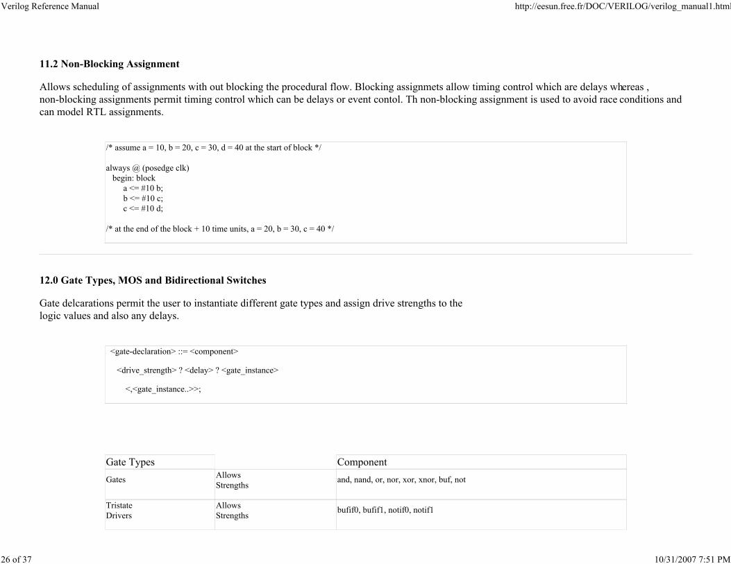
11.2 Non-Blocking Assignment
Allows scheduling of assignments with out blocking the procedural flow. Blocking assignmets allow timing control which are delays whereas ,
non-blocking assignments permit timing control which can be delays or event contol. Th non-blocking assignment is used to avoid race conditions and
can model RTL assignments.
/* assume a = 10, b = 20, c = 30, d = 40 at the start of block */
always @ (posedge clk)
begin: block
a <= #10 b;
b <= #10 c;
c <= #10 d;
/* at the end of the block + 10 time units, a = 20, b = 30, c = 40 */
12.0 Gate Types, MOS and Bidirectional Switches
Gate delcarations permit the user to instantiate different gate types and assign drive strengths to the
logic values and also any delays.
<gate-declaration> ::= <component>
<drive_strength> ? <delay> ? <gate_instance>
<,<gate_instance..>>;
Gate Types Component
GatesAllows
Strengthsand, nand, or, nor, xor, xnor, buf, not
Tristate
Drivers
Allows
Strengthsbufif0, bufif1, notif0, notif1
Verilog Reference Manual http://eesun.free.fr/DOC/VERILOG/verilog_manual1.html
27 of 37 10/31/2007 7:51 PM
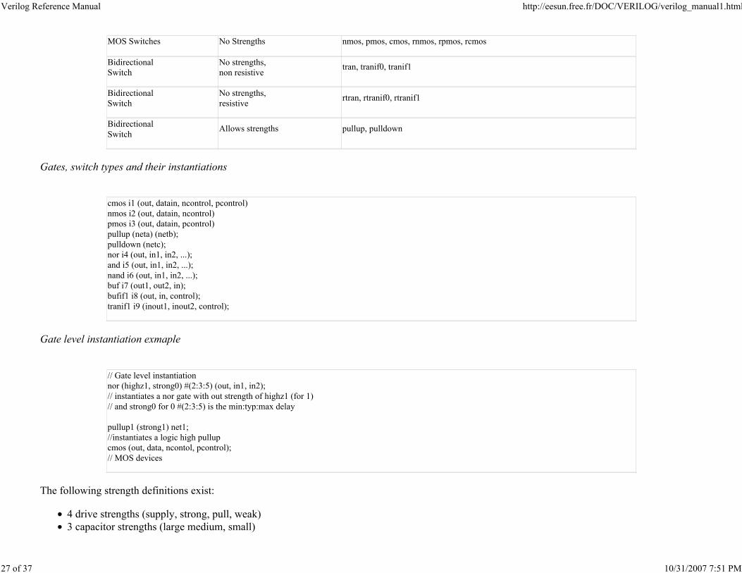
MOS Switches No Strengths nmos, pmos, cmos, rnmos, rpmos, rcmos
Bidirectional
Switch
No strengths,
non resistivetran, tranif0, tranif1
Bidirectional
Switch
No strengths,
resistivertran, rtranif0, rtranif1
Bidirectional
SwitchAllows strengths pullup, pulldown
Gates, switch types and their instantiations
cmos i1 (out, datain, ncontrol, pcontrol)
nmos i2 (out, datain, ncontrol)
pmos i3 (out, datain, pcontrol)
pullup (neta) (netb);
pulldown (netc);
nor i4 (out, in1, in2, ...);
and i5 (out, in1, in2, ...);
nand i6 (out, in1, in2, ...);
buf i7 (out1, out2, in);
bufif1 i8 (out, in, control);
tranif1 i9 (inout1, inout2, control);
Gate level instantiation exmaple
// Gate level instantiation
nor (highz1, strong0) #(2:3:5) (out, in1, in2);
// instantiates a nor gate with out strength of highz1 (for 1)
// and strong0 for 0 #(2:3:5) is the min:typ:max delay
pullup1 (strong1) net1;
//instantiates a logic high pullup
cmos (out, data, ncontol, pcontrol);
// MOS devices
The following strength definitions exist:
4 drive strengths (supply, strong, pull, weak)
3 capacitor strengths (large medium, small)
Verilog Reference Manual http://eesun.free.fr/DOC/VERILOG/verilog_manual1.html
28 of 37 10/31/2007 7:51 PM
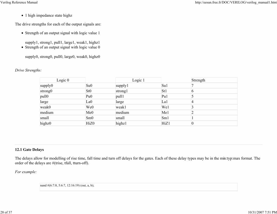
1 high impedance state highz
The drive strengths for each of the output signals are:
Strength of an output signal with logic value 1
supply1, strong1, pull1, large1, weak1, highz1
Strength of an output signal with logic value 0
supply0, strong0, pull0, large0, weak0, highz0
Drive Strengths:
Logic 0 Logic 1 Strength
supply0 Su0 supply1 Su1 7
strong0 St0 strong1 St1 6
pull0 Pu0 pull1 Pu1 5
large La0 large La1 4
weak0 We0 weak1 We1 3
medium Me0 medium Me1 2
small Sm0 small Sm1 1
highz0 HiZ0 highz1 HiZ1 0
12.1 Gate Delays
The delays allow for modelling of rise time, fall time and turn off delays for the gates. Each of these delay types may be in the min:typ:max format. The
order of the delays are #(trise, tfall, tturn-off).
For example:
nand #(6:7:8, 5:6:7, 12:16:19) (out, a, b);
Verilog Reference Manual http://eesun.free.fr/DOC/VERILOG/verilog_manual1.html
29 of 37 10/31/2007 7:51 PM
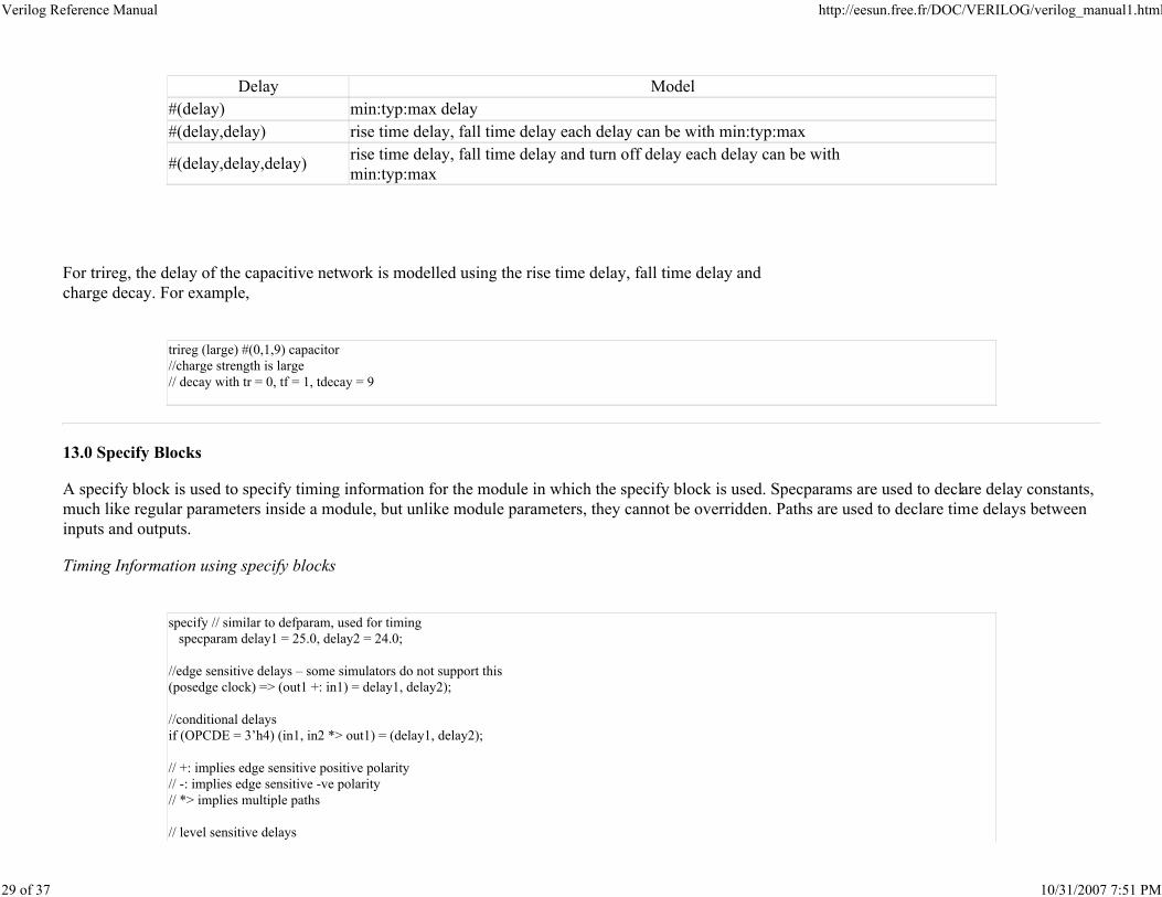
Delay Model
#(delay) min:typ:max delay
#(delay,delay) rise time delay, fall time delay each delay can be with min:typ:max
#(delay,delay,delay)rise time delay, fall time delay and turn off delay each delay can be with
min:typ:max
For trireg, the delay of the capacitive network is modelled using the rise time delay, fall time delay and
charge decay. For example,
trireg (large) #(0,1,9) capacitor
//charge strength is large
// decay with tr = 0, tf = 1, tdecay = 9
13.0 Specify Blocks
A specify block is used to specify timing information for the module in which the specify block is used. Specparams are used to declare delay constants,
much like regular parameters inside a module, but unlike module parameters, they cannot be overridden. Paths are used to declare time delays between
inputs and outputs.
Timing Information using specify blocks
specify // similar to defparam, used for timing
specparam delay1 = 25.0, delay2 = 24.0;
//edge sensitive delays – some simulators do not support this
(posedge clock) => (out1 +: in1) = delay1, delay2);
//conditional delays
if (OPCDE = 3’h4) (in1, in2 *> out1) = (delay1, delay2);
// +: implies edge sensitive positive polarity
// -: implies edge sensitive -ve polarity
// *> implies multiple paths
// level sensitive delays
Verilog Reference Manual http://eesun.free.fr/DOC/VERILOG/verilog_manual1.html
30 of 37 10/31/2007 7:51 PM
if (clock) (in1, in2 *> out1, out2) = 30
// setuphols
$setuphols(posedge clock &&& reset, in1 &&& reset,
3:5:6, 2:3:6);
(reset *> out1, out2) = (2:3:5,3:4:5);
endspecify
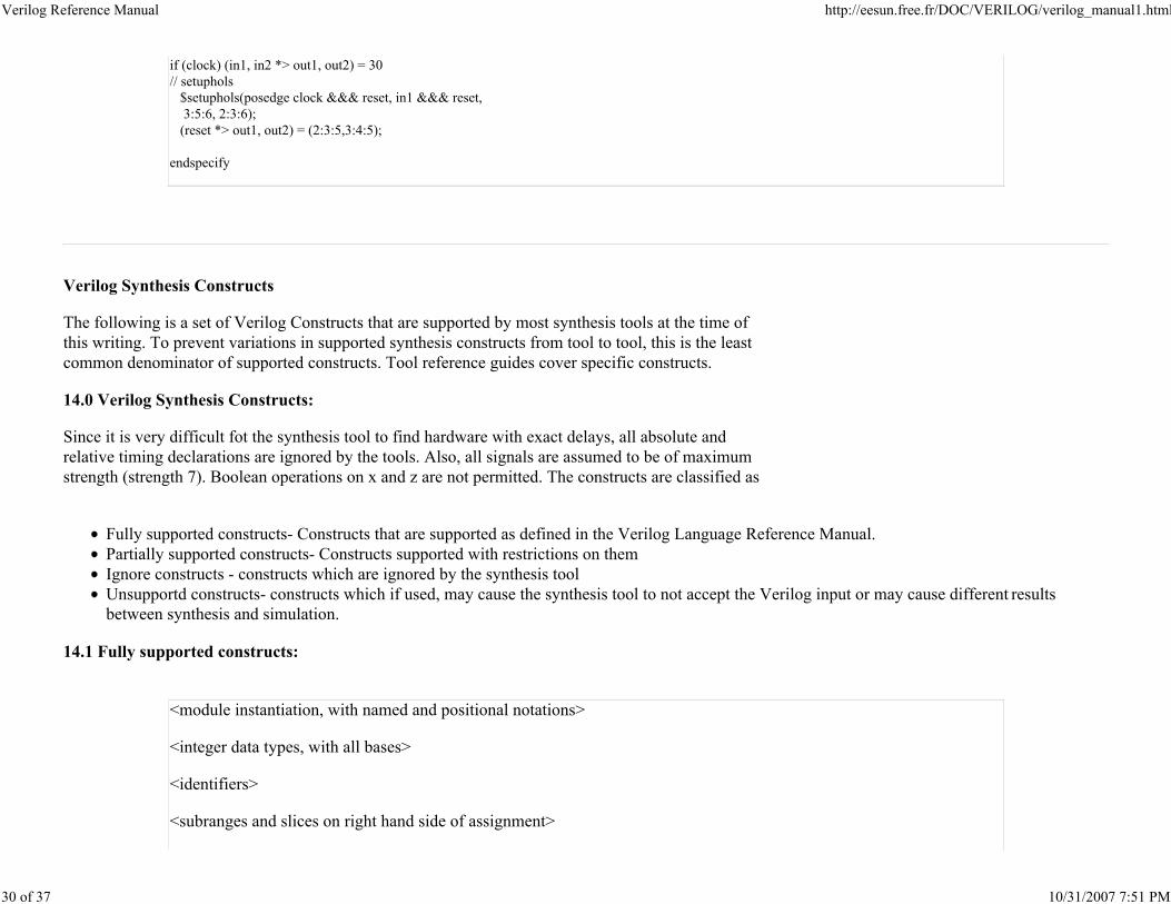
Verilog Synthesis Constructs
The following is a set of Verilog Constructs that are supported by most synthesis tools at the time of
this writing. To prevent variations in supported synthesis constructs from tool to tool, this is the least
common denominator of supported constructs. Tool reference guides cover specific constructs.
14.0 Verilog Synthesis Constructs:
Since it is very difficult fot the synthesis tool to find hardware with exact delays, all absolute and
relative timing declarations are ignored by the tools. Also, all signals are assumed to be of maximum
strength (strength 7). Boolean operations on x and z are not permitted. The constructs are classified as
Fully supported constructs- Constructs that are supported as defined in the Verilog Language Reference Manual.
Partially supported constructs- Constructs supported with restrictions on them
Ignore constructs - constructs which are ignored by the synthesis tool
Unsupportd constructs- constructs which if used, may cause the synthesis tool to not accept the Verilog input or may cause different results
between synthesis and simulation.
14.1 Fully supported constructs:
<module instantiation, with named and positional notations>
<integer data types, with all bases>
<identifiers>
<subranges and slices on right hand side of assignment>
Verilog Reference Manual http://eesun.free.fr/DOC/VERILOG/verilog_manual1.html
31 of 37 10/31/2007 7:51 PM
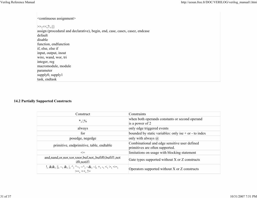
<continuous assignment>
>>,<<,?:,{}
assign (procedural and declarative), begin, end, case, casex, casez, endcase
default
disable
function, endfunction
if, else, else if
input, output, inout
wire, wand, wor, tri
integer, reg
macromodule, module
parameter
supply0, supply1
task, endtask
14.2 Partially Supported Constructs
Construct Constraints
*,/,%when both operands constants or second operand
is a power of 2
always only edge triggered events
for bounded by static variables: only ise + or - to index
posedge, negedge only with always @
primitive, endprimitive, table, endtableCombinational and edge sensitive user defined
primitives are often supported.
<= limitations on usage with blocking statement
and,nand,or,nor,xor,xnor,buf,not,,bufif0,bufif1,not
if0,notif1Gate types supported without X or Z constructs
!, &&, ||, ~, &, |, ^, ^~, ~^, ~&, ~|, +, -, <, >, <=,
>=, ++, !=Operators supported without X or Z constructs
Verilog Reference Manual http://eesun.free.fr/DOC/VERILOG/verilog_manual1.html
32 of 37 10/31/2007 7:51 PM
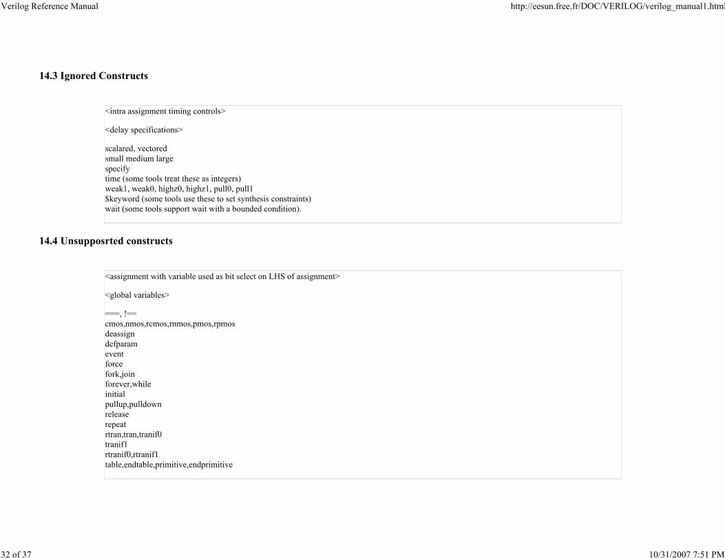
14.3 Ignored Constructs
<intra assignment timing controls>
<delay specifications>
scalared, vectored
small medium large
specify
time (some tools treat these as integers)
weak1, weak0, highz0, highz1, pull0, pull1
$keyword (some tools use these to set synthesis constraints)
wait (some tools support wait with a bounded condition).
14.4 Unsupposrted constructs
<assignment with variable used as bit select on LHS of assignment>
<global variables>
===, !==
cmos,nmos,rcmos,rnmos,pmos,rpmos
deassign
defparam
event
force
fork,join
forever,while
initial
pullup,pulldown
release
repeat
rtran,tran,tranif0
tranif1
rtranif0,rtranif1
table,endtable,primitive,endprimitive
Verilog Reference Manual http://eesun.free.fr/DOC/VERILOG/verilog_manual1.html
33 of 37 10/31/2007 7:51 PM
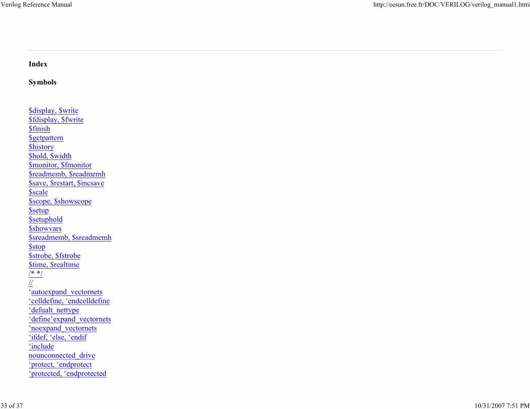
Index
Symbols
$display, $write
$fdisplay, $fwrite
$finish
$getpattern
$history
$hold, $width
$monitor, $fmonitor
$readmemb, $readmemh
$save, $restart, $incsave
$scale
$scope, $showscope
$setup
$setuphold
$showvars
$sreadmemb, $sreadmemh
$stop
$strobe, $fstrobe
$time, $realtime
/* */
//
‘autoexpand_vectornets
‘celldefine, ‘endcelldefine
‘defualt_nettype
‘define’expand_vectornets
‘noexpand_vectornets
‘ifdef, ‘else, ‘endif
‘include
nounconnected_drive
‘protect, ‘endprotect
‘protected, ‘endprotected
Verilog Reference Manual http://eesun.free.fr/DOC/VERILOG/verilog_manual1.html
34 of 37 10/31/2007 7:51 PM
‘remove_gatename
‘noremove_gatenames
‘remove_netname
‘noremove_netnames
‘resetall
‘signed
‘unsigned
‘timescale
‘unconnected_drive
A
Arithemtic Operators
Arrays
B
Binary Expressions
blocking assignment
C
case
casex
casez
compiler directives
Combinational UDP example
continuous assignment
D
delays
disable
E
equality operators
escaped identifiers
expressions
F
for
forever
Verilog Reference Manual http://eesun.free.fr/DOC/VERILOG/verilog_manual1.html
35 of 37 10/31/2007 7:51 PM
fork ... join
Fully supported synthesis constructs
function and function example
G
gate declaration
gate-types
I
if, if ... else
integer literals
identity operators
Ignored Synthesis Constructs
L
logical opeators
M
memories
module
N
named blocks
nets
non-blocking assigments
numbers
O
operator precedence
operators
P
partially supported synthesis constructs
procedural assignments
pulldown
Verilog Reference Manual http://eesun.free.fr/DOC/VERILOG/verilog_manual1.html
36 of 37 10/31/2007 7:51 PM
pullup
R
reg, register
relational operators
repeat
reserved words
S
scalared
sequential edge sensitive UDP
sequential level sensitive UDP
Shift, other operators
shm_open
shm_probe
specify block
specparam
string symbols
supply0
supply1
switch types
synthesis constructs
synthesis ignored constructs
synthesis unsupported constructs
T
task and task example
tri0
tri1
triand
trior
trireg
U
UDP
unary expression
unary, bitwise and reduction operators
Verilog Reference Manual http://eesun.free.fr/DOC/VERILOG/verilog_manual1.html
37 of 37 10/31/2007 7:51 PM
Unsupported Synthesis Constructs
V
vectored
W
wait
wand
while
wire
wor
X
x, X
Z
z, Z


![Verilog Quick Reference Card - ee.imperial.ac.uk Quic… · 2. QUALLS Verilog HDL QUICK REFERENCE CARD Revision 2.1 3. 4. 5. PARALLEL STATEMENTS assign [(strengthl, strengthO)] WIRID](https://img.pdfslide.net/doc/110x75/5f05d1e57e708231d414deae/verilog-quick-reference-card-ee-quic-2-qualls-verilog-hdl-quick-reference.jpg)