Embed Size (px)
Citation preview
8/8/2019 (Verrry Good) Sdl Basics
http://slidepdf.com/reader/full/verrry-good-sdl-basics 1/20
1
SDL Basics
Rolv Bræk a
aSintef Delab, N-7034 Trondheim, NorwayE-mail: [email protected]
Abstract
This tutorial is a quick introduction to the basic ideas, concepts and features of SDL. It startsby introducing the class of systems that SDL is intended for and the main features of their be-haviour. The correspondence between these features and the basic concepts of SDL are ex-plained. Then the various language elements of SDL are introduced gradually and exemplifiedby way of a simple system example. Finally, a brief summary of the basic language elementscovered by this tutorial is provided. The more advanced features of SDL are explained in thecompanion tutorial [1].
8/8/2019 (Verrry Good) Sdl Basics
http://slidepdf.com/reader/full/verrry-good-sdl-basics 2/20
2
SDL Basics
1. INTRODUCTION
1.1. The needs
The Specification and Description Language SDL is designed for systems that are:
• reactive;• concurrent;• real-time;• distributed;• heterogeneous.
The SDL development started early in the era of Stored Programme Control (SPC) switch-ing systems. At that time, in the late 1960s - early 1970s, it became clear to telephone manu-facturers and administrations alike that neither programming languages nor hardwaredescription languages provided the basis for the clear and concise communication they neededto successfully develop and maintain the new generations of highly complex switching sys-tems. It is fair to say that the challenges facing those developments were formidable. The tech-nology itself was young and needing to be developed as part of the projects. The applicationswere highly complex, representing heavy traffic loads and real time demands, and they shouldbe continuously operational with a minimum of malfunctioning. Switching systems were, andprobably still are, among the most complex real-time systems in existence. Facing such chal-lenges, it is not surprising that the communication industry became pioneers in the develop-ment of systems engineering languages and methods. Nor is it surprising that a languagedeveloped to serve such difficult conditions, turned out to be useful far beyond the telecommu-nication industry for which it was originally intended.
The first issue for the SDL development was to provide a better way to describe behaviour .Behaviour was in focus because:
• behaviour is vital to the purpose and quality of this kind of systems;• behaviour is difficult to describe clearly due to its dynamic, invisible and often infinite
nature;• behaviour is often very complex and hard to overview.
Better ways to describe behaviour are still considered to be indispensable from any seriousattempt to improve in systems and software engineering. “Better” is here relative to traditionalprograms and hardware descriptions in supporting:
• human communication and understanding;• formal analysis and comparison of behaviours;• alternative implementations and design optimisation.
SDL is intended to be used in several ways:
• for international standards in the communication area: to define unambiguous and
8/8/2019 (Verrry Good) Sdl Basics
http://slidepdf.com/reader/full/verrry-good-sdl-basics 3/20
3
consistent standards;• for use in tendering: to specify the required behaviour and to compare provided behav-
iour from different vendors;• for use in systems development: to specify the required system behaviour, to design
and generate an optimal implementation and to document the provided behaviour;• for verification and validation of behaviour.
Consequently, SDL should be suitable for implementation-independent specification of be-haviour as well as for description of the behaviour actually implemented. Hence the name Spec-ification and Description Language - SDL.
In summary: a language was sought that was both intelligible to human beings, formalenough to support analysis and comparison of behaviours, implementation independent, and re-alistic in the sense that it could adequately describe real system behaviour. Nothing less!
SDL has developed gradually both in coverage and formality. The first recommendation of the language, appearing in 1976, focused on sequential behaviour, only making a few basic as-sumptions about concurrency. Later, in the 1984 recommendation, notations for architecturalcomposition were added. Finally, in 1992, came powerful notions of types and inheritance mak-ing SDL a full blown object oriented language [5]-[9].
1.2. The concepts
In every language design, assumptions about the problem domain have to be made andmapped to language concepts. Suitability for a given class of problems is largely determined bythe conceptual match between the problem domain and the language.
In the case of SDL, the problem domain is reactive behaviour. The need is to say as little as
possible about the internal, physical construction of the systems, while telling the full storyabout how external stimuli and responses are related at the interfaces. The basic concepts of SDL were chosen to match the characteristic features of such interfaces, see Table 1. The choiceof basic concepts clearly positioned SDL as an object-based language from the very beginning.Also as a concurrent and formal language based on communicating finite state machines. Theconcepts may seem very “physical” at first. Looking closer, however, it is evident that they arenot bound to any particular technology. They are neither specific to hardware, nor to software.At the same time they neither exclude implementations in hardware nor in software. In fact,they allow for many alternative ways of implementation giving the designer freedom to opti-mise for non-functional requirements concerning, for instance, response times and traffic loads.
At the same time the underlying theory of communicating state machines provides a firm basisfor analysis and comparison as well as an abstraction that enables us to describe control behav-iour clearly and realistically.
An important decision was to make the same assumptions about internal interfaces as aboutexternal interfaces. Not only does it allow us freedom to place the system boundary where welike, it also provides us with distribution transparency. There are no built in assumptions aboutphysical co-localisation of processes. One is free to distribute processes as one sees fit in the
8/8/2019 (Verrry Good) Sdl Basics
http://slidepdf.com/reader/full/verrry-good-sdl-basics 4/20
4
implementation.
While these basic concepts may be sufficient to describe sequential and concurrent behav-
iour, they are not sufficient for efficient handling of entire system descriptions. The systems wedeal with are often very complex and composed from subsystems that may be interconnected,re-used and configurated in many different ways. As any viable language, SDL needs conceptsfor composition, generalisation and re-use. These are:
composition:• of process behaviours from sub-sequences called procedures;• of blocks from processes and signal routes;• of systems and blocks from blocks and channels;
generalisation and re-use:
• type concepts for signals, procedures, data, services, processes, blocks and sys-tems;• defining new types by (single) inheritance from other types;• type libraries as packages.
This tutorial will concentrate on the basic concepts and on composition. More advanced useof types and inheritance will be treated in the companion paper [1].
2. THE LANGUAGE
Concepts alone do not make a language. Syntactic form is also needed. Unimportant as it
may seem, the syntactic form matters quite a bit for the practical usefulness. SDL has two con-
Table 1 Characteristic features of the problem domain related to basic SDL.
Problem domain SDL concept
Concurrency External users and other systems operate
concurrently and demand to be served
concurrently by the system.
The system and the environment operate
concurrently with respect to each other.
SDL systems are composed from proc-
esses that behave concurrently with each
other.
The environment is assumed to be com-
posed in a similar manner.
Communica-tion
The environment interacts with the system
through a number of concurrent interfaces.
The physical distances vary.
The system and the environment interact
by signalling, not by direct manipulation.
Processes communicate through concur-
rent signal routes and channels. There are
no constraints on the distance covered by
channels and signal routes.
Processes interact (mainly) by signals and
cannot manipulate the internal state or data
of each other.
Sequentialbehaviour
On each individual interface, the system is
expected to behave sequentially in stimuli-
response fashion, driven by external
events. The responses of the system
depend on real-time conditions and on
data stored in the system.
Processes are extended finite state
machines with timers. They behave in dis-
crete state transition steps like a finite state
machine, but have the additional ability to
store and manipulate data, and to super-
vise time.

8/8/2019 (Verrry Good) Sdl Basics
http://slidepdf.com/reader/full/verrry-good-sdl-basics 5/20
5
crete syntaxes:
• SDL/GR which is a graphic representation;• SDL/PR which is a textual representation.
The graphic form is preferred by most people for actual specification and description work,as it is more intuitive and displays relationships more clearly than the textual form. Fragmentsin the textual form are embedded in the graphic form where text is more suitable, e.g. for datadeclarations, signal declarations and operations.
The textual form looks a bit like a programming language. It has the advantage that it doesnot require any expensive tools, but can be edited using an ordinary text processor. Its main useand purpose is to serve as a vendor independent exchange format between tools. In that role ithas the disadvantage that graphic layout information is lost. Therefore a new interchange lan-
guage, CIF, is currently being developed which also caters for layout information.SDL makes a rather strict separation between object structure and behaviour. Contrary to
some other languages, a process is not just a piece of behaviour. It is an object with a fully de-fined behaviour that may only be composed in parallel with other objects to form a structure of objects with concurrent behaviour.
SDL deals with structure in a different way than object models in OMT [3], entity-relation-ship diagrams, or dataflow diagrams, see e.g.[4]. In SDL it is possible to identify instances, andshow the architectural structure of a system in terms of its instances, much in the same fashionas a blueprint for a machine or house shows its parts. This feature of the language enables us tomodel structural distribution and interconnection aspects of a system.
The language makes a clear distinction between types and instances. A type may be defined
separately, and instances can be generated in the context of many systems. Unless otherwisestated, we will take the word “process” to mean process instance, and use “process type” to referto the concept. Similarly for systems, blocks and signals.
3. DESCRIBING STRUCTURE
3.1. System level
In SDL, behaviour is always performed in the context of a system. It does not matter if it isa simple behaviour composed from a single process, or a complex behaviour composed from alarge number of processes organised in a hierarchy of blocks. The starting point is always a top
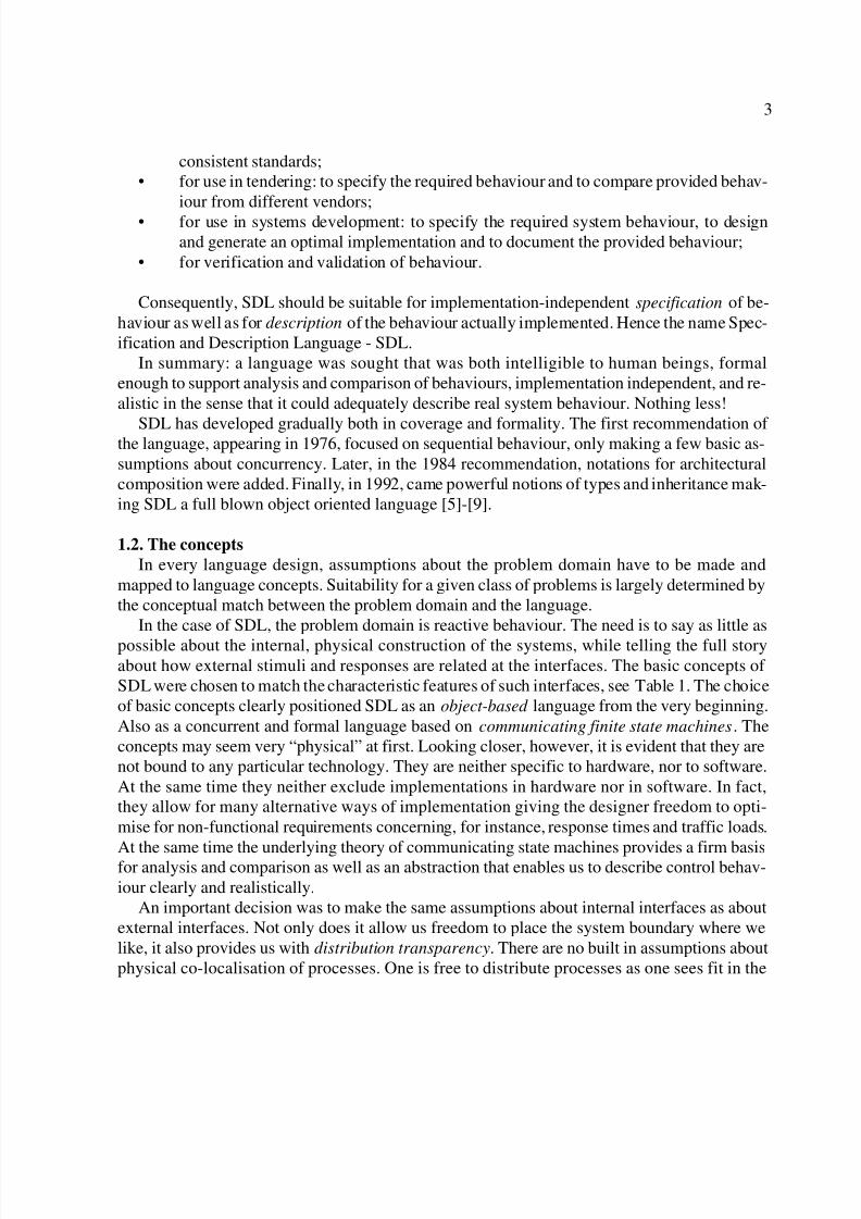
level description of a system. Let us start straight away with a system description. Spend a littletime studying Figure 1 before you read on. Are you able to understand anything about the sys-tem from reading this top level description?
A system diagram like this, does not tell us very much when studied in isolation. Figure 1simply tells us that this particular system is composed of one block called AccessControlUnit ,a set of 100 similar blocks called ap of type AccessPoint and a block called op of type Opera-
tionPoint .The (100) ap blocks are connected to the environment through (100) channels called Panel
and (100) channels called Door, and to the AccessControlUnit through (100) channels calledValidation. The op block is connected to the environment through a channel called Terminal
and to the AccessControlUnit through a channel called Operation. The signals passed in each
direction over the channels are indicated by signal lists attached to the arrows on the channels.
8/8/2019 (Verrry Good) Sdl Basics
http://slidepdf.com/reader/full/verrry-good-sdl-basics 6/20
6
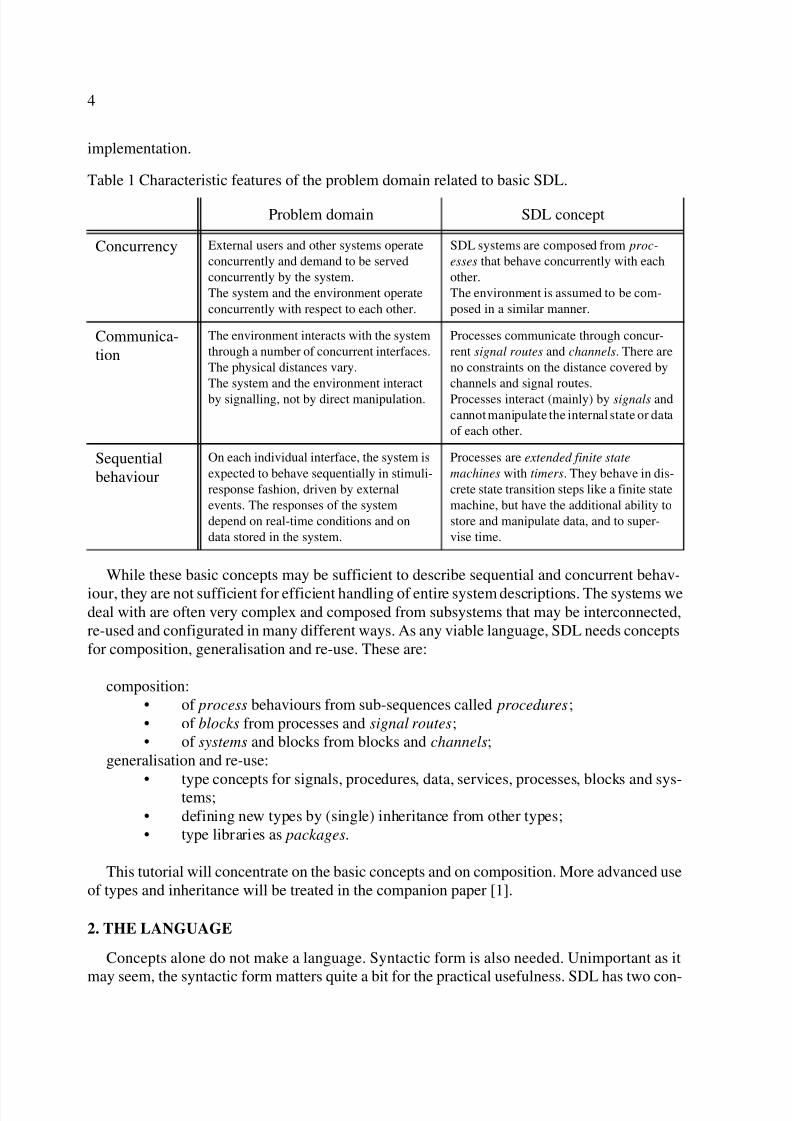
These signals are declared on the second page of the diagram, shown in Figure 2. On this page
we also find references to the type definitions for AccessPoint and OperationPoint .Altogether this tells us that the system will interact with the environment through many
concurrent channels, and that each channel will be served independently by a block. Since each
Figure 1. A System diagram example, page 1.
Frame symbol
Heading Page
Block Reference
Channel name Signal list
Block set
Typebased block definition
gate name
SYSTEM AccessControl 1(2)
Access
Validation
[(Pin)][(Pout)]
[(Resp)] [(Req)]ap(100):p
v AccessPanel
Door d
Operation
[(Tin)][(Tout)][(Ack)] [(Modify)]
op:
t o OperationTerminal Point
Point[(Dout)]
UnitControl
[(Din)]
Channel with delay
Channel without delay
Figure 2. Page 2 of the system diagram.
SYSTEM AccessControl 2(2)
AccessPoint OperationPoint
SIGNAL
Digit(Integer), Card(Integer), Pass, AccessDenied, EnterPIN, EnterCard,
DoorPassed, Open, Close, Validate(Integer, Integer), ConfigReq, Accepted,
Rejected, Configure(Integer);
SIGNALLIST Pout = Pass, AccessDenied, EnterPIN, EnterCard;
SIGNALLIST Pin = Digit, Card;
SIGNALLIST Dout = Open, Close;SIGNALLIST Din = DoorPassed;
SIGNALLIST Req = Validate, ConfigReq;
SIGNALLIST Resp = Accepted, Rejected, Configure;
SIGNALLIST Tout =... /*continue until all signallists are defined*/;
NEWTYPE.../* Define global, system specific datatypes, if necessary*/
page 2(of2)
block typereference
signaldefinitions
signallists
data (type)definitions
text symbol
signal name
comment
parametertypes

8/8/2019 (Verrry Good) Sdl Basics
http://slidepdf.com/reader/full/verrry-good-sdl-basics 7/20
7
block will contain at least one process, we know that the system behaviour will contain at leastas many concurrent processes as there are blocks. From the system name, block names, channelnames and signal names we may guess that the system will provide some kind of access controlfunctionality. Apart from this, the system diagram tells little about the behaviour. The remain-ing details are hidden inside the block and channel definitions. So, in order to understand more,we must proceed with these. The language elements of system diagrams are summarised in Sec-tion 5.1. If you are a newcomer to SDL it may be a good idea to read that section before youcontinue.
3.2. Block level
Already by presenting the system level, we have indirectly demonstrated some features thatare essential to manage complex systems:
• Top down decomposition. We have started to approach the details of the system grad-ually, in top down fashion. This is a good way to reach understanding of an existingsystem, although it may not be the way it was developed.
• Bottom up composition. We have seen that the system is composed from user definedcomponents. These components may be arbitrarily complex entities.
• Reusable component types. We have seen that components may be defined separatelyas types, allowing instances to be instantiated many places with little effort.
There are two important differences between systems and blocks:
• Blocks can only occur as components inside systems and blocks.
• Systems cannot occur as components neither in systems nor in blocks.
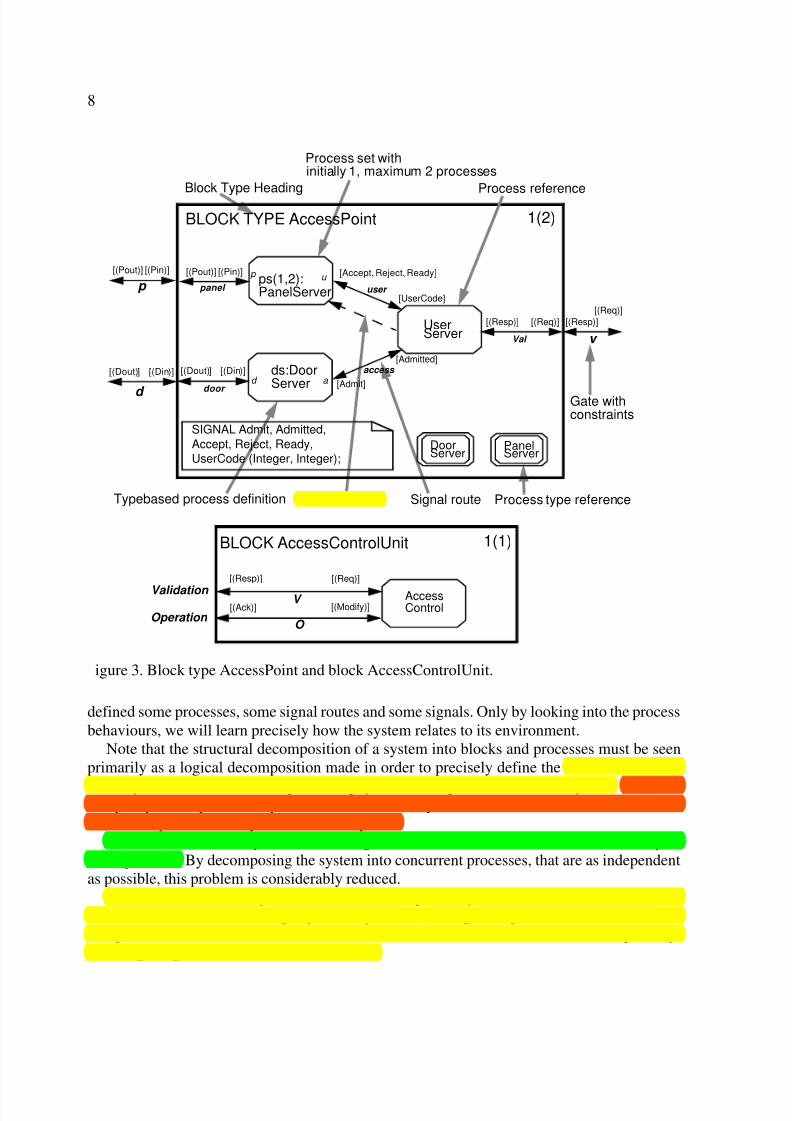
Hence, systems only occur at the top level, while blocks only occur inside. Blocks are con-tainers like systems. They are decomposed into blocks and channels recursively over as manylevels as one desires until the basic components, processes, are reached. Figure 3 is an exampleshowing a block type diagram for AccessPoint and a block diagram for AccessControlUnit (wegive no examples of blocks decomposed into blocks here). In these example diagrams we definethe blocks in terms of which processes they contain. Again, spend a little time trying to under-stand these diagrams before reading on.
From the diagrams we learn that each block of type AccessPoint contains a process called
UserServer , a process called ds of type DoorServer , and one or two processes called ps of typePanelServer . We also learn that a PanelServer may be created dynamically by the UserServer .Note that we only need to define local signals here, as those defined on the outer block level arestill known.
The AccessControlUnit contains a single process called AccessControl. In SDL it is not al-lowed to mix blocks and processes in the same diagram, and it is not allowed to have processesat the system level, only at the block level. This is one reason why the AccessControlUnit wasrepresented as a block at the system level, although it contains only one process.
The names we have used so far seem to indicate that we are dealing with a system where theuser interface will consist of panels and doors. Indeed, it is a system for access control in build-ings, where users identify themselves using a card with a magnetic strip and a personal identi-
fication number (PIN). However, this is only informal meaning. Formally, we have only
8/8/2019 (Verrry Good) Sdl Basics
http://slidepdf.com/reader/full/verrry-good-sdl-basics 8/20
8
defined some processes, some signal routes and some signals. Only by looking into the processbehaviours, we will learn precisely how the system relates to its environment.
Note that the structural decomposition of a system into blocks and processes must be seenprimarily as a logical decomposition made in order to precisely define the abstract behaviour
of the system. It need not correspond to a physical decomposition of the real system. There aremany ways to map an SDL system into a concrete implementation, and some of those will bestructured quite differently from the SDL system.
A well known difficulty when describing reactive behaviour is the so-called “state explo-sion” problem. By decomposing the system into concurrent processes, that are as independentas possible, this problem is considerably reduced.
We have now identified processes that behave sequentially and will be able to describe theirbehaviour without encountering any state explosion. Although the system contains hundreds of independent threads of behaviour, we are now able to concentrate on each thread separately.We are getting closer to the core of SDL now.
igure 3. Block type AccessPoint and block AccessControlUnit.
BLOCK AccessControlUnit 1(1)
Validation
[(Resp)] [(Req)]
Operation [(Ack)] [(Modify)]
AccessControl
V
O
Block Type Heading
Process set with
Process create Signal route
Gate withconstraints
initially 1, maximum 2 processes
Process reference
Process type referenceTypebased process definition
BLOCK TYPE AccessPoint 1(2)
[(Pin)][(Pout)]
p
v
d
[(Dout)] [(Din)]
[(Req)]
[(Resp)]
ps(1,2):PanelServer
ds:DoorServer
UserServer Val
[(Req)][(Resp)]
[(Pin)][(Pout)]
[(Dout)] [(Din)]
panel
door
[Accept, Reject, Ready]
[UserCode]
[Admit]
[Admitted]
user
access
DoorServer
PanelServer
SIGNAL Admit, Admitted,
Accept, Reject, Ready,
UserCode (Integer, Integer);
p u
d a
8/8/2019 (Verrry Good) Sdl Basics
http://slidepdf.com/reader/full/verrry-good-sdl-basics 9/20
9
4. THE BEHAVIOUR
4.1. The SDL “machine”
SDL processes are described as extended Finite State Machines, FSM. The FSM is excel-lently suited for the purpose of SDL as it allows stimuli-response behaviours to be describedclearly, completely and unambiguously in terms of external stimuli and responses. For this rea-son the FSM is widely used in such diverse areas as hardware design, protocol design, compilerdesign and software engineering methods. It has gained a widespread popularity, and is nowincluded in one form or another, in many software engineering methods. SDL is special in theparticular form of extended FSM it uses, in its formal definition and in the way concurrentFSMs communicate and may be composed into large systems.
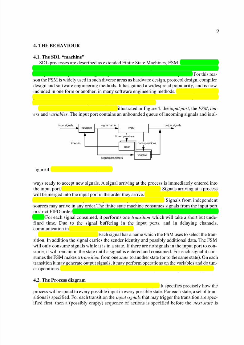
Each process consists of four main parts illustrated in Figure 4: the input port , the FSM , tim-
ers and variables. The input port contains an unbounded queue of incoming signals and is al-
ways ready to accept new signals. A signal arriving at the process is immediately entered intothe input port, where it remains until it is consumed by the FSM. Signals arriving at a processwill be merged into the input port in the order they arrive. If two signals arrive at the same time,the conflict is resolved by selecting an arbitrary sequential order. Signals from independentsources may arrive in any order.The finite state machine consumes signals from the input portin strict FIFO order except when the order is modified by the save operator (see the next sec-tion). For each signal consumed, it performs one transition which will take a short but unde-fined time. Due to the signal buffering in the input ports, and in delaying channels,communication in SDL is said to be asynchronous.
Signals are discrete messages. Each signal has a name which the FSM uses to select the tran-
sition. In addition the signal carries the sender identity and possibly additional data. The FSMwill only consume signals while it is in a state. If there are no signals in the input port to con-sume, it will remain in the state until a signal is entered and consumed. For each signal it con-sumes the FSM makes a transition from one state to another state (or to the same state). On eachtransition it may generate output signals, it may perform operations on the variables and do tim-er operations. This state-transition behaviour of the FSM is expressed in a process diagram.
4.2. The Process diagram
The main content of a process diagram is the process graph. It specifies precisely how theprocess will respond to every possible input in every possible state. For each state, a set of tran-sitions is specified. For each transition the input signals that may trigger the transition are spec-
ified first, then a (possibly empty) sequence of actions is specified before the next state is
igure 4. Illustration of an SDL process.
input port FSM
timer
variable
output signalsinput signals
timeouts
Signal parameters
signal name
timer operations
data operations
8/8/2019 (Verrry Good) Sdl Basics
http://slidepdf.com/reader/full/verrry-good-sdl-basics 10/20
10
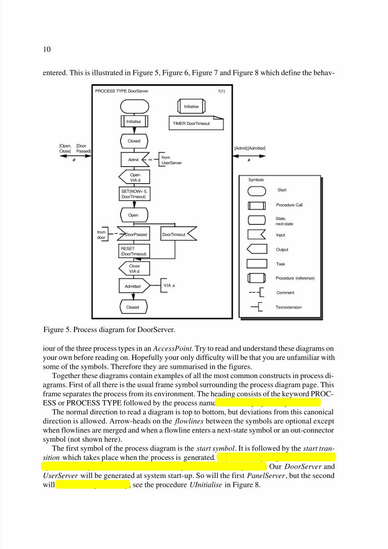
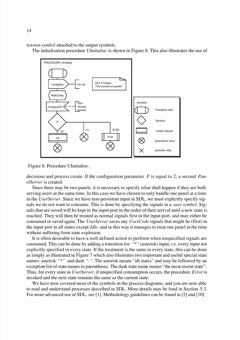
entered. This is illustrated in Figure 5, Figure 6, Figure 7 and Figure 8 which define the behav-
iour of the three process types in an AccessPoint . Try to read and understand these diagrams onyour own before reading on. Hopefully your only difficulty will be that you are unfamiliar withsome of the symbols. Therefore they are summarised in the figures.
Together these diagrams contain examples of all the most common constructs in process di-
agrams. First of all there is the usual frame symbol surrounding the process diagram page. Thisframe separates the process from its environment. The heading consists of the keyword PROC-ESS or PROCESS TYPE followed by the process name followed by optional parameters.
The normal direction to read a diagram is top to bottom, but deviations from this canonicaldirection is allowed. Arrow-heads on the flowlines between the symbols are optional exceptwhen flowlines are merged and when a flowline enters a next-state symbol or an out-connectorsymbol (not shown here).
The first symbol of the process diagram is the start symbol. It is followed by the start tran-
sition which takes place when the process is generated. A process may be generated either atsystem start-up, or as a result of a create request from another process. Our DoorServer andUserServer will be generated at system start-up. So will the first PanelServer , but the secondwill be created dynamically, see the procedure UInitialise in Figure 8.
Figure 5. Process diagram for DoorServer.
PROCESS TYPE DoorServer
Open
VIA d
Initialise
Initialise
SET(NOW+ 5,DoorTimeout)
Closed
a
[Admit] [Admitted]
1(1)
from
UserServerAdmit
TIMER DoorTimeout;
Open
Closed
DoorTimeout
Close
VIA d
AdmittedVIA a
RESET
(DoorTimeout)
DoorPassedfrom
door
Start
State,
next state
Comment
Text extension
Procedure Call
Procedure (reference)
Task
Input
Output
Symbols
[Open,
Close]
d
[Door
Passed]
8/8/2019 (Verrry Good) Sdl Basics
http://slidepdf.com/reader/full/verrry-good-sdl-basics 11/20
11
In all these processes initialisation is performed by calling a procedure, so as not to clutterthe main diagram with initialisation details. Procedures help to achieve top down decomposi-tion as well as bottom up composition of process behaviours. Note that procedure diagrams arereferenced using a procedure (reference) symbol in the same manner as block and process typesmay be referenced.
It is a good idea to concentrate on the stimuli-response behaviour first when reading andmaking process graphs. What are the states, and what are the main sequences of inputs and out-puts specified by the diagram? The DoorServer process is the simplest of the three process typesin the example, with the purest state transition behaviour. It has no data, but uses a timer called DoorTimeout , which is declared inside the text symbol. It has two states: Closed and Open. Af-ter initialisation it will remain in the Closed state until it receives an Admit signal from the Us-
erServer . This signal causes a transition to the Open state while performing two actions:
1. The signal Open is output via gate d . This means that the signal will be transmittedthrough the channel connected to gate d and passed on to a process that is able to re-ceive the signal. In this case the receiver will be somewhere in the environment.
2. The timer DoorTimeout is SET . If the timer has not been reset when the specified pointin time, NOW+5, is reached, it will enter a signal with the same name as the timer intothe input port. NOW is a pre-defined operation that returns the current real-time value.
In the state Open, two transitions are specified:
1. The signal DoorPassed is consumed causing the process to RESET (that is to stop) thetimer, output the signals Close and Admitted and enter state Closed .
2. The DoorTimeout is consumed causing a similar transition as above, except that thetimer is not reset (because it has already expired).
What if the process consumes a signal which is unspecified in the current state? In that case,the signal is simply discarded and the process remains in the same state. This mechanism is re-ferred to as non-persistent input, and is important to bear in mind.
In these process diagrams the destination of output signals has been specified either insidethe output symbols, or in text extension symbols attached to them. Text extensions can be usedwith any of the symbols to extend the area available for text. The sender of input signals hasbeen indicated too, in comment symbols attached to the input symbols. The fine difference be-
tween text extension symbols and comment symbols should be noted: for text extensions theassociation line is solid while it is dashed for comments. Note that there is no way in SDL toformally specify the sender of input signals. In these diagrams we have added this informationas informal comments only as an aid to the reader. Normally when reading process graphs, welike to look up the sender of input signals and the receiver of output signals to increase our un-derstanding of the overall behaviour. From a testing point of view the added information of which process should be the sender is of considerable value.
Apparently what the DoorControl process does is to open a door (somewhere in the environ-ment) on command from the UserServer , and to close the door after it has been passed or themaximum time has elapsed, and inform the UserServer when this has happened.
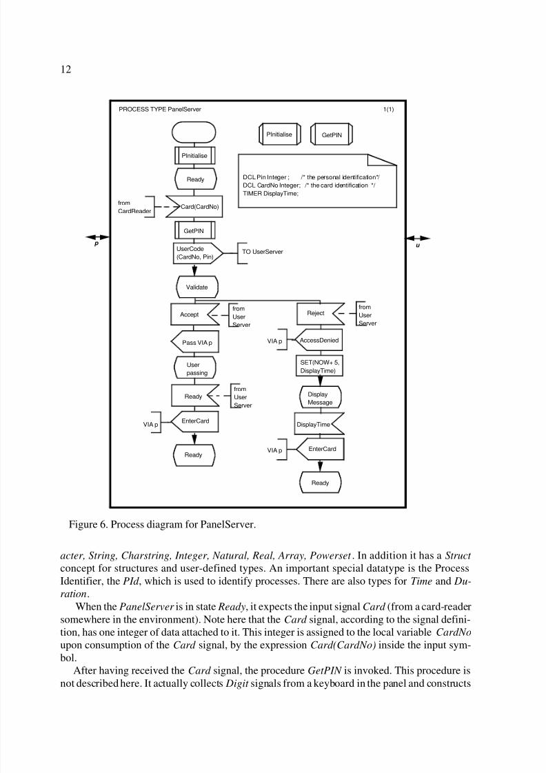
The PanelServer process is slightly more complex than the DoorServer . It uses two variables
Pin and CardNo which are both Integers. SDL supports the normal data types: Boolean, Char-
8/8/2019 (Verrry Good) Sdl Basics
http://slidepdf.com/reader/full/verrry-good-sdl-basics 12/20
12
acter, String, Charstring, Integer, Natural, Real, Array, Powerset . In addition it has a Struct
concept for structures and user-defined types. An important special datatype is the ProcessIdentifier, the PId , which is used to identify processes. There are also types for Time and Du-
ration.When the PanelServer is in state Ready, it expects the input signal Card (from a card-reader
somewhere in the environment). Note here that the Card signal, according to the signal defini-tion, has one integer of data attached to it. This integer is assigned to the local variable CardNo
upon consumption of the Card signal, by the expression Card(CardNo) inside the input sym-bol.
After having received the Card signal, the procedure GetPIN is invoked. This procedure isnot described here. It actually collects Digit signals from a keyboard in the panel and constructs
Figure 6. Process diagram for PanelServer.
1(1)PROCESS TYPE PanelServer
PInitialise
PInitialise
SET(NOW+ 5,
DisplayTime)
Ready
Validate
Ready
GetPIN
GetPIN
UserCode
(CardNo, Pin)TO UserServer
Ready
Display
Message
DisplayTime
DCL Pin Integer ; /* the personal identification*/
DCL CardNo Integer; /* the card identification */
TIMER DisplayTime;
User
passing
Card(CardNo)from
CardReader
from
User
Server
Accept
from
User
Server
Reject
Ready
from
User
Server
EnterCard
Pass VIA p AccessDenied
EnterCard
p u
VIA p
VIA p
VIA p

8/8/2019 (Verrry Good) Sdl Basics
http://slidepdf.com/reader/full/verrry-good-sdl-basics 13/20
13
a PIN value which it assigns to the Pin variable. The value of the CardNo and the Pin variablesare then communicated to the UserServer in the output UserCode(CardNo, Pin). We have hereillustrated an important principle: signal parameters are copied into local variables upon con-sumption, and from local variables into signals upon sending. There is no other way to accessthe parameters of input signals than to copy them into local variables.
In the UserServer we see how the UserCode signal is treated at the receiving end. Upon con-
sumption the parameter values are copied into local variables, which happen to have the samename as in the PanelServer . They are then sent on to the Validation process in the Validate sig-nal issued via the signalroute Val. Since there may be two panels in an AccessPoint , the identityof the current panel is stored by the expression CurrentPS := SENDER. (Note that CurrentPS
is declared as a PId variable). SENDER is a built-in operation that returns the PId of the senderof the input signal just consumed. This value is used to direct the response back to the correct
panel later on using the expression TO CurrentPS which, in this diagram, is placed in a text ex-
Figure 7. Process diagram for UserServer.
1(1)PROCESS UserServer
UInitialise
UInitialise
Idle
Validation
UserPassing
Error
Validate
(CardNo, Pin)VIA Val
Idle
TO
ds Admit
DCL Pin Integer ; /* the personal identification*/
DCL CardNo Integer; /* the card identification*/
DCL CurrentPS Pid; /* the current panel server instance*/
CurrentPS:=
SENDER
AcceptTO
CurrentPS
UserCode
ReadyTO
CurrentPS
Idle
*
Error
*
from
PanelServer
UserCode
(CardNo, Pin)
Accepted
from
Access
Control
Rejected
from
Access
Control
RejectTO
CurrentPS
UserCodefrom
dsAdmitted
save
Symbol
*
*
any state
not
specified
input
next state
equals
current
8/8/2019 (Verrry Good) Sdl Basics
http://slidepdf.com/reader/full/verrry-good-sdl-basics 14/20
14
tension symbol attached to the output symbols.The initialisation procedure UInitialise is shown in Figure 8. This also illustrates the use of
decisions and process create. If the configuration parameter P is equal to 2, a second Pan-elServer is created.Since there may be two panels, it is necessary to specify what shall happen if they are both
serving users at the same time. In this case we have chosen to only handle one panel at a timein the UserServer . Since we have non-persistent input in SDL, we must explicitly specify sig-nals we do not want to consume. This is done by specifying the signals in a save symbol. Sig-nals that are saved will be kept in the input port in the order of their arrival until a new state isreached. They will then be treated as normal signals first in the input port, and may either beconsumed or saved again. The UserServer saves any UserCode signals that might be (first) inthe input port in all states except Idle, and in this way it manages to treat one panel at the timewithout suffering from state explosion.
It is often desirable to have a well defined action to perform when unspecified signals areconsumed. This can be done by adding a transition for “*” (asterisk) input, i.e. every input notexplicitly specified in every state. If the treatment is the same in every state, this can be doneas simply as illustrated in Figure 7 which also illustrates two important and useful special statenames: asterisk “*” and dash “-”. The asterisk means “all states” and may be followed by anexception list of state names in parentheses. The dash state name means “the most recent state”.Thus, for every state in UserServer , if unspecified consumption occurs, the procedure Error isinvoked and the next state remains the same as the current state.
We have now covered most of the symbols in the process diagrams, and you are now ableto read and understand processes described in SDL. More details may be fond in Section 5.3.For more advanced use of SDL, see [1]. Methodology guidelines can be found in [2] and [10].
WaitConfig
ConfigReq VIA Val
Configure(P)
from
Access
Control
P
Error
(2)(1) ELSE
ps
Procedure start
Decision
Create request
(procedure) return
(process) stop
DCL P Integer;
/*the number of panels*/
Symbols
PROCEDURE UInitialise
Figure 8. Procedure UInitialise.
8/8/2019 (Verrry Good) Sdl Basics
http://slidepdf.com/reader/full/verrry-good-sdl-basics 15/20
15
5. LANGUAGE SUMMARY
5.1. System diagrams
A system diagram is illustrated in Figure 1 and Figure 2.Frame Symbol
The system itself is represented by a frame symbol which represents the boundary of the sys-tem. Outside the frame is the environment , which is not described. Similar frame symbols areused in all the different SDL diagrams to delimit the entity being defined from its environment. Heading
In the upper left corner inside the frame, we find a heading. It consists of a text which startswith the keyword SYSTEM followed by the name of the system, here AccessControl. The head-ing is also a common feature of all diagrams, but the keyword will depend on the actual kind of entity being defined.
Page numbersIn the upper right corner there are two numbers. These are page numbers. The first number
is the number of the current page, i.e. 1 for the first page, and the second number is the numberof pages this diagram consists of, i.e. 2 pages in this case. SDL diagrams may in general, takeup several pages and the page numbering is always done in the same way. Block interaction area
Inside the frame, we find the body of the system defined in terms of blocks and channels. Italso defines the channels connecting the system to the environment.
• Block symbols. Blocks are represented by rectangular symbols, each representing ei-ther a single block or a set of similar blocks. The content of the symbol may take threedifferent forms:
i. Block reference. This is simply a name. The name refers to a separate block di-agram which contains the actual definition of the block. This is always a singularblock.
ii. Typebased block definition. In this case the symbol contains a block name and ablock type name separated by a colon, and an optional number of instances. Italso contains one or more gate names. The block type which is referred to mayeither be defined locally, as is the case here, or in a surrounding scope unit. Sinceblock types are defined independently of how instances are interconnected, theyhave gates to which external channels may be connected.
iii. Block diagram. It is possible to define the block directly nested inside the block
symbol. This is not shown in our example, and is not very practical for largersystems.• Channel symbols. The only way to pass signals between blocks are through channels.
Channels are represented by lines with arrowheads indicating the direction of signalflow through the channel. The signals of a channel are denoted by a list of signals (andsignallists) in brackets. The flow may be either uni-directional or bi-directional. Thereare two kinds of channels:i. Channels with no delay. In this case the arrowheads are placed at the ends.ii. Channels with delay. In this case the arrowheads are not placed at the ends, but
somewhere along the lines. These channels have an implicit FIFO queue in eachdirection, and may delay a signal for an arbitrary time.
Both kinds of channel will deliver the signals at the destination endpoint in the same

8/8/2019 (Verrry Good) Sdl Basics
http://slidepdf.com/reader/full/verrry-good-sdl-basics 16/20
16
order as they were entered into the channel. If two signals are presented simultaneous-ly to the channel they will be entered into the channel in arbitrary order. A channelconnected to a block set will actually represent a set of channel instances, thus thereare actually 100 instances of the Validation channel in our system.Every channel (or set of channels) must have a name, and the channel endpoints areattached to the blocks that the channel connects to or to the frame symbol in case thechannel is a link to the environment.
Type in system area.
An example of this area is found at the top of Figure 2. Here we define block types, processtypes, service types and procedures which are local to the system. It is possible to define typeseither directly, or by reference. In Figure 2 the type definitions for AccessPoint and Operation-
Point are referenced using a double sided rectangle containing the type name. The purpose of these symbols is to indicate where the type definitions are localised without having to provide
the full definition at that point.Text symbols
Text symbols contain declarations and informal text. They are not specific for system dia-grams, but occur in all kinds of SDL diagrams. In system and block diagrams text symbols willcontain:
• Signal definitions. In SDL it is necessary to declare all signals such that they are visi-ble to the processes which handle them. Signals are declared inside text symbols. Thedeclaration gives the signal name and the type of its parameters, if any.
• Signallists. Often the list of signals associated with a channel is quite comprehensiveand the diagram becomes crowded. Signallists help to remedy this. A signallist is a listof signals which has been given a name. The list may also include timer signals or oth-
er signallist names. If a signallist contains other signallists, the signallist names willappear in parentheses.
• Data definitions. Definitions of local data types.• Notes. A note is an explanatory text embraced by /* ... */.
5.2. Block diagrams
Block diagrams are illustrated in Figure 3. Block diagrams are very similar to system dia-grams. There is a frame symbol, an interaction area, a type definition area and text symbols.The differences are the following:
• Heading. The keyword is either BLOCK or BLOCK TYPE. If it is “block type”, thename may be followed by formal context parameters and a specialisation. This willbe explained in the paper [1].
• Gate definitions. Gates are identified by a gate name and a gate symbol. These are likesignal route symbols, but attached outside the frame symbol. Gates can be comparedwith “plugs” of household appliances. They are used to “plug” up instances correctly.The (optional) signallists help to ensure that the instances of the block type are con-nected properly to their surroundings. Note that gates are used only with types. Thesymbols outside the frame of a singular block like AccessControlUnit , represent theactual channels connected to that block.
• Block substructure area. Here the body of the block is defined in terms of blocks and
channels in the same way as the body of a system diagram. This alternative is not
8/8/2019 (Verrry Good) Sdl Basics
http://slidepdf.com/reader/full/verrry-good-sdl-basics 17/20
17
shown in our example, but is used in more complex cases where we need to decomposeblocks over several levels before reaching the processes. A block contains either aprocess interaction area (see below) or a substructure area. It may also contain both, inwhich case they are considered as alternative definitions of the block.
• Process interaction area. Here the body of the block is defined in terms of processes
and signal routes. Signal routes look exactly like channels without delay. They are de-fined in the same way and behave in the same way. Process symbols differ slightlyfrom block symbols, so it is easy to see that it is a different kind of entity. In similarfashion as blocks, the processes appear in three forms:i. Process reference. This is a process symbol containing a name which refers to a
process definition in a separate diagram. It may optionally specify a minimumand maximum number of instances, where the minimum number is created whenthe system is created, and the remaining may be created dynamically.
ii. Typebased process definition. This is a process symbol containing a processname and a type name separated by a colon, and optionally a range of instancesin the same way as above.
iii. Process diagram. This is a diagram, defining the process behaviour, directly inthe process interaction area. This option is only useful for very small diagramsand is not illustrated here.
• Type in block area. As in system diagrams, this is the place for local definition of block types, process types, service types and procedures.
• Data definitions. Block types may contain data type definitions, but no variable decla-rations.
5.3. Process diagramsProcess diagrams follow the same overall principles that are used in all SDL diagrams: there
is a frame symbol and a heading. Outside the frame are gates, if the diagram defines a processtype. Inside we find an area containing the process graph itself, we find text symbols containingdeclarations, and we find (procedure) reference symbols. The following is a brief summary of the main elements that are special to process diagrams. Heading
The keyword is either PROCESS or PROCESS TYPE. Processes may have parameters.These are local variables that will receive initial values when the process is created.Process graph
• Start. There is one and only one start symbol per process diagram. It is followed by thestart transition which is triggered when the process is created.• State, nextstate. States are designated by a state name. State symbols with the same
name represent the same state.• Input . Input symbols specify the signal name and also to which local variables the sig-
nal parameters shall be assigned, if any.• Output . Output symbols specify the signal name and the value of signal parameters, if
any. In addition they may specify the destination process by a TO-clause and/or a VIA-
clause. The TO-clause specifies the destination process either by name (e.g. TO ds inFigure 7) or by a PId value (e.g. TO CurrentPS in Figure 7). The VIA-clause is usedto list the path of signalroutes and channels which the signal will be sent through (e.g.
VIA Val in Figure 7). The VIA-clause may also specify a gate. If the TO- and VIA-

8/8/2019 (Verrry Good) Sdl Basics
http://slidepdf.com/reader/full/verrry-good-sdl-basics 18/20
18
clauses are omitted, there must be a unique destination for the signal based on its sig-nal name.
• Save. The save symbol lists the names of signals that shall be saved, and not con-sumed, in a state.
• Task . A task is used to set the values of data by assignments. A task symbol may con-tain a list of assignments separated by commas. Alternatively a task symbol may con-tain informal text , where formal assignments are not considered appropriate. The righthand side of the assignment operator symbol represents the expression. Variable oc-currences on the right of an assignment operator mean extracting the value from thevariable. Variables on the left of the assignment operator are modified to become theexpression value of the right hand side.
• Timer operations. Timer operations are placed inside task symbols. When a timer hasnot been SET, it is inactive. When it is SET, it becomes active. A timer is set with a
TIME value. If an active timer is SET it continues to be active with the new TIMEvalue. RESET causes the timer to become inactive and ensures that the timeout signalwill not be consumed by the process.
• Decision. The decision symbol is used to choose between different alternative coursesof action upon a question. The question is written within the decision symbol and maybe either a formal expression (such as the one in our example) or informal text. Oneach of the flowlines from the decision symbol there is an answer. The course of ac-tion will follow the line where the correct answer is associated. Decisions change thecontrol flow according to values of internal variables, while state/input constructschange control flow according to external stimuli. Often it is a matter of design wheth-er we use state and signals or decisions.
• Procedure call. The procedure call symbols resemble the procedure (reference) sym-bols, but their corners are different. Note that a procedure call symbol has one and onlyone entrance and one and only one exit.
• Create request. This causes a process instance to be created and given initial parame-ter values. Only members of process sets where the maximum number of instanceshave not been reached may be created. Note that blocks cannot be created dynamical-ly. In block diagrams (see Figure 3) the creation may be shown by a dashed line fromthe parent process to the offspring process.
• Stop. While processes are created by their parent (or implicitly at start-up time), proc-esses may not kill each other. Processes terminate if they reach a Stop symbol. When
a process has terminated, any attempt to reference that process will result in an error.Text area.
• Variables. Variables in SDL are declared very much the same way as in programminglanguages. DCL is the keyword which precedes data declarations. A list of names fol-lows that is terminated by the sort name. Sort is the SDL technical term for what isnormally called data type.
• Timers and Time. A timer is declared similarly to a variable. Time is a special data typeand is mainly used in connection with timers. The expression “NOW+5” is a time val-ue, and it adds the time-expression NOW and the Duration 5 (here seconds). NOW isan operator of the time data type and it returns the current real-time. Duration is an-other special data type and it is also mainly used in connection with timers. Timers are
just like alarm clocks. They will issue time-out signals when their time is reached.
8/8/2019 (Verrry Good) Sdl Basics
http://slidepdf.com/reader/full/verrry-good-sdl-basics 19/20
19
There may very well be several different timers active at the same time.• Process Identifier, PId . Each SDL process has a unique identification which is a value
of the data type PId . PId expressions are used mainly as the destination of output. PIdvalues are obtained from the following PId expressions which are predefined in allprocesses:i. SELF – this process itself.ii. OFFSPRING – the most recent process instance created by this process.iii. PARENT – the creating process, if this process was dynamically created.iv. SENDER – the sender of the signal most recently consumed by this process.
• Data types. SDL has predefined types which are quite similar to those we know fromprogramming languages. In addition it is possible to define new data types using gen-erators and structures. It is also possible to define entirely new types, using an axio-matic approach.
Comment and text extension symbolsThese are very similar, but they are distinguishable by the association line. The association
line for a comment symbol is dashed, while for text extension it is solid. As the name suggests,a text extension is an extension of the text within the symbol.Type in process area.
This area contains service type diagrams and/or procedure diagrams, or references to suchdiagrams. Only procedure (reference) symbols have been shown in the examples here.Procedure diagrams.
Procedures are scope units and they may have their own variable declarations. Procedurescontain the same mechanisms for describing behaviour as are found in processes, but proce-dures are not actors of their own. The interpretation is performed by the process in which they
are declared. Special features of procedure diagrams are:• Parameters. Procedures are defined with formal parameters that receive actual values
when the procedure is invoked. Parameters may be passed either by value, which is thedefault, or by reference.
• Procedure start and Return symbols. Two special symbols represent the start of theprocedure and the return from the procedure.
5.4. Additional features
SDL offers a number of features in addition to those presented here. A few of them are brief-ly mentioned below.
Shared variablesWe have emphasised that data is not shared among the processes. However, there are situa-tions where several processes need to access the same variables. In such cases the variables arestill owned by one and only one process. Other processes may gain access to the values, eitherby normal signal exchange, or by two special constructs:
• Reveal/view. By declaring a variable as revealed , it is possible for other processes inthe same block to view (but not change) the value.
• Export/import . By declaring a value as exported , it is possible for processes even inother blocks to see the value by importing it. This export/import construct is actuallya shorthand for queries using normal signals.
Services
Sometimes the behaviour of a process is composed from sub-functions or services that are
8/8/2019 (Verrry Good) Sdl Basics
http://slidepdf.com/reader/full/verrry-good-sdl-basics 20/20
20
quite independent, and possible to describe in separate process graphs. As an alternative to de-scribing the behaviour of such a process as one finite state machine in one process diagram,SDL offers the opportunity to decompose the process into several finite state machines, calledservices, which are described by separate process graphs. The services share the input port of the process, and may also share variables. Only one service at a time is allowed to perform atransition, so there is no danger of interference on shared variables. Services cannot be ad-dressed from the outside, so input signals are directed to the correct services on the basis of thesignal names only. Consequently the services must be uniquely identified by the signal name. Remote procedures
SDL offers a remote procedure construct that allows processes to call procedures which be-long to other processes. Like export/import, this is not a basic mechanism in SDL, but a short-hand for an underlying communication using normal SDL signals. Enabling conditions
It is possible to make signal consumption dependent on so called enabling conditions, whichare boolean expressions placed in a special symbol on transitions. Such transitions will only beperformed if the expression evaluates to true.
6. ACKNOWLEDGEMENT
The example presented in this tutorial has been inspired by a similar example in the SDLmethodology book by Bræk and Haugen [2]. The author is grateful to Øystein Haugen and Ri-chard Sanders for thoroughly reviewing this tutorial at an early stage and for giving many val-uable suggestions.
7. REFERENCES
1. Sarma, A. (1995) SDL-92. Tutorial at the 7th SDL Forum. Ibid.2. Bræk, R. and Haugen, Ø. (1993) Engineering Real Time Systems. An object-oriented
methodology using SDL. Hemel Hempstead: Prentice Hall. ISBN 0-13-034448-6.3. Rumbaugh, J., Blaha, M., Premerlani, W., Eddy, F. and Lorensen, W (1991) Object-Ori-
ented Modelling and Design. Englewood Cliffs: Prentice-Hall.ISBN 0-13-630054-5.4. Yourdon E. (1989) Modern structured analysis. Englewood Cliffs: Prentice-Hall. ISBN
0-13-598632-X.5. Z.100 (1994), CCITT Specification and description language (SDL), ITU-T.6. Z.100 C (1994), Initial algebra model. Annex C to Z.100, ITU-T.
7. Z.100 D (1994), SDL predefined data. Annex D to Z.100, ITU-T.8. Z.100 F2 (1994), Specification and description language (SDL) - SDL formal definition:
Static semantics, ITU-T.9. Z.100 F3 (1993), Specification and description language (SDL) - SDL formal definition:
Dynamic semantics, ITU-T Apr. 94.10. Reed, R. Methodology for Real Time Systems.Tutorial at the 7th SDL Forum. Ibid.


![[GOOD READ] Data Cabinet Basics](https://img.pdfslide.net/doc/110x75/5695cf611a28ab9b028dd895/good-read-data-cabinet-basics.jpg)