Embed Size (px)
Citation preview
VersaNail® Humeral Universal Nailing System
Product Rationale & Surgical Technique

1
VersaNail® Humeral Universal Nailing System
Contents
Note: This brochure presents a surgical technique available for use with the Biomet, Inc., VersaNail® Platform instruments and implants. Surgeons may need to make modifications as appropriate in their own surgical tech-nique with these devices depending on individual patient requirements.
Design Summary .......................................................................................................................................................... 3
Implant Overview.......................................................................................................................................................... 4
Precautions .................................................................................................................................................................. 7
Antegrade Entry and Canal Preparation ...................................................................................................................... 8
Antegrade Nail Insertion ............................................................................................................................................. 14
Antegrade Locking ..................................................................................................................................................... 16
Retrograde Entry and Canal Preparation ................................................................................................................... 19
Retrograde Nail Insertion ........................................................................................................................................... 21
Retrograde Locking .................................................................................................................................................... 23
End Cap Placement and Nail Removal ...................................................................................................................... 26
Ordering Information .................................................................................................................................................. 27
Flexible Reaming System ........................................................................................................................................... 32
2
VersaNail® Humeral Universal Nailing System
3
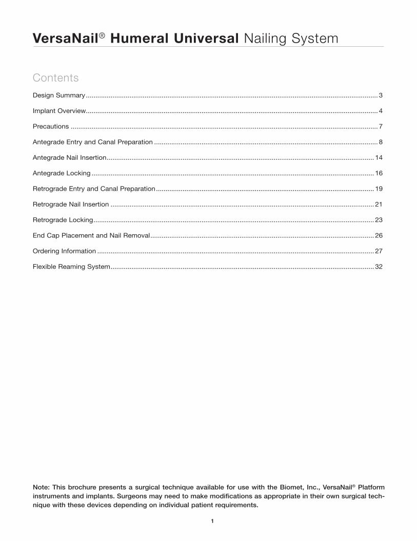
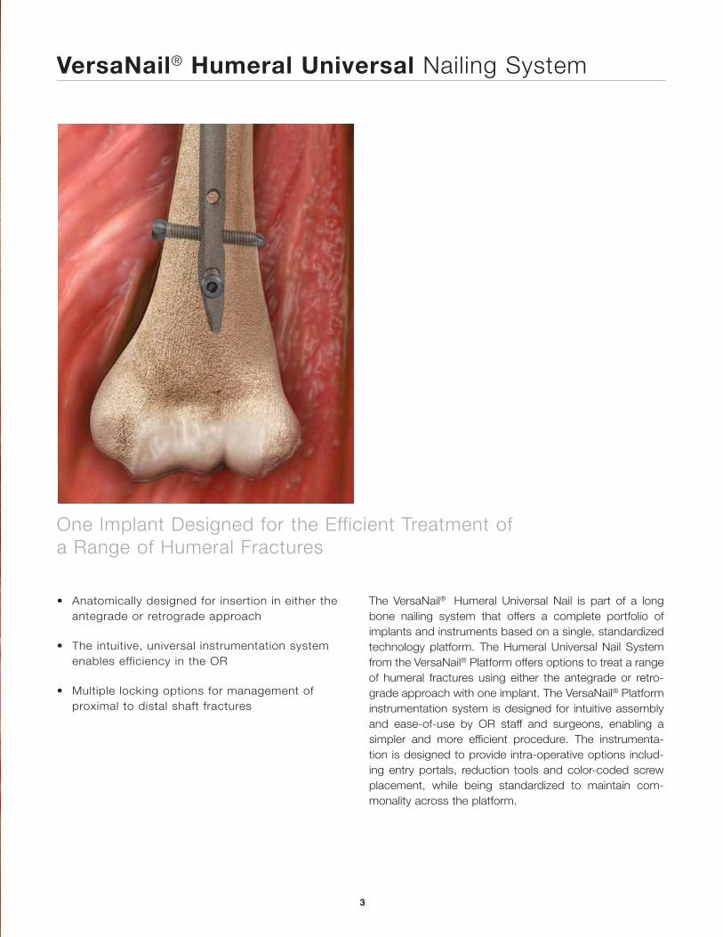
One Implant Designed for the Efficient Treatment of a Range of Humeral Fractures
The VersaNail® Humeral Universal Nail is part of a long bone nailing system that offers a complete portfolio of implants and instruments based on a single, standardized technology platform. The Humeral Universal Nail System from the VersaNail® Platform offers options to treat a range of humeral fractures using either the antegrade or retro-grade approach with one implant. The VersaNail® Platform instrumentation system is designed for intuitive assembly and ease-of-use by OR staff and surgeons, enabling a simpler and more efficient procedure. The instrumenta-tion is designed to provide intra-operative options includ-ing entry portals, reduction tools and color-coded screw placement, while being standardized to maintain com-monality across the platform.
• Anatomically designed for insertion in either the antegrade or retrograde approach
• The intuitive, universal instrumentation system enables efficiency in the OR
• Multiple locking options for management of proximal to distal shaft fractures
VersaNail® Humeral Universal Nailing System
4
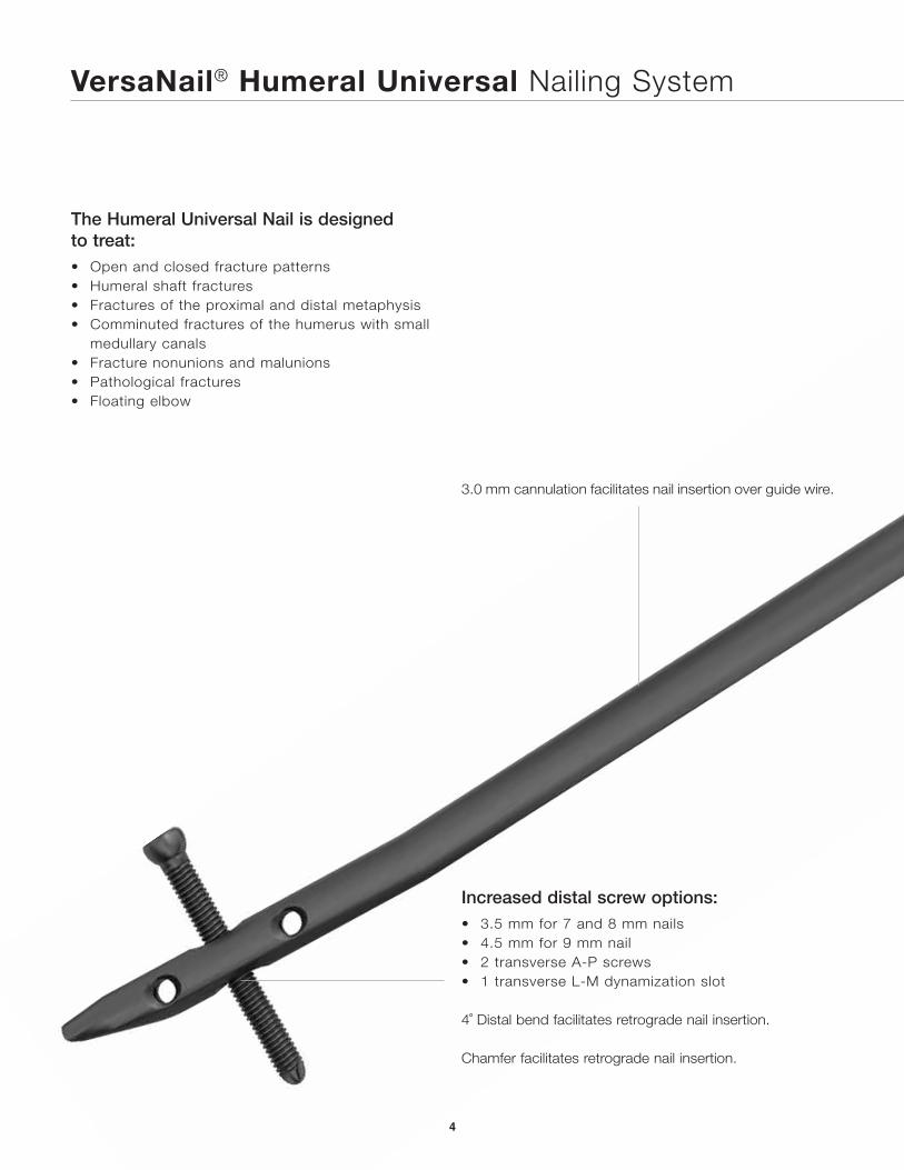
The Humeral Universal Nail is designed to treat:• Open and closed fracture patterns• Humeral shaft fractures• Fractures of the proximal and distal metaphysis• Comminuted fractures of the humerus with small
medullary canals• Fracture nonunions and malunions• Pathological fractures• Floating elbow
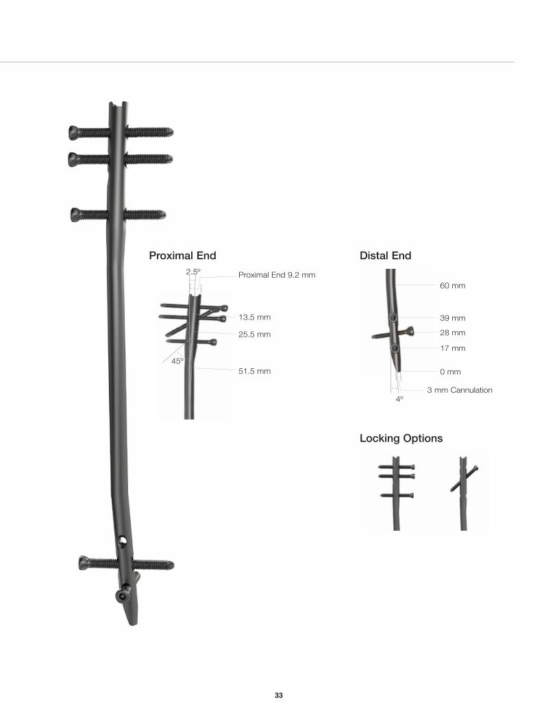
3.0 mm cannulation facilitates nail insertion over guide wire.
Increased distal screw options:• 3.5 mm for 7 and 8 mm nails• 4.5 mm for 9 mm nail• 2 transverse A-P screws• 1 transverse L-M dynamization slot
4˚ Distal bend facilitates retrograde nail insertion.
Chamfer facilitates retrograde nail insertion.
2.5º
45º
13.5 mm
25.5 mm
51.5 mm
Proximal End 9.2 mm
0 mm
17 mm
28 mm
39 mm
60 mm
3 mm cannulation4º
5
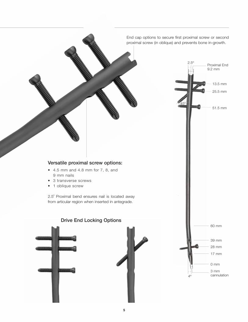
Versatile proximal screw options:• 4.5 mm and 4.8 mm for 7, 8, and
9 mm nails• 3 transverse screws• 1 oblique screw
2.5˚ Proximal bend ensures nail is located away from articular region when inserted in antegrade.
Drive End Locking Options
End cap options to secure first proximal screw or second proximal screw (in oblique) and prevents bone in-growth.
VersaNail® Humeral Universal Nailing System
6
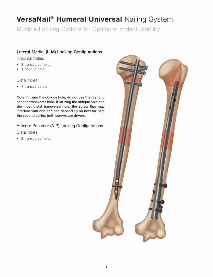
Multiple Locking Options for Optimum Implant Stability
Lateral-Medial (L-M) Locking Configurations
Proximal holes:• 3 transverse holes• 1 oblique hole
Distal holes:• 1 transverse slot
Note: If using the oblique hole, do not use the first and second transverse hole. If utilizing the oblique hole and the most distal transverse hole, the screw tips may interfere with one another, depending on how far past the second cortex both screws are driven.
Anterior-Posterior (A-P) Locking Configurations
Distal holes:• 2 transverse holes
7
Precautions
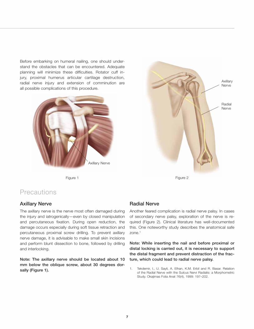
Axillary NerveThe axillary nerve is the nerve most often damaged during the injury and iatrogenically—even by closed manipulation and percutaneous fixation. During open reduction, the damage occurs especially during soft tissue retraction and percutaneous proximal screw drilling. To prevent axillary nerve damage, it is advisable to make small skin incisions and perform blunt dissection to bone, followed by drilling and interlocking.
Note: The axillary nerve should be located about 10 mm below the oblique screw, about 30 degrees dor-sally (Figure 1).
Axillary Nerve
Figure 1
Axillary Nerve
Radial Nerve
Figure 2
Radial NerveAnother feared complication is radial nerve palsy. In cases of secondary nerve palsy, exploration of the nerve is re-quired (Figure 2). Clinical literature has well-documented this. One noteworthy study describes the anatomical safe zone.1
Note: While inserting the nail and before proximal or distal locking is carried out, it is necessary to support the distal fragment and prevent distraction of the frac-ture, which could lead to radial nerve palsy.
1. Tekdemir, I., U. Sayli, A. Elhan, K.M. Erbil and R. Basar. Relation of the Radial Nerve with the Sulcus Nervi Radialis: a Morphometric Study. Okajimas Folia Anat 76(4), 1999: 197–202.
Before embarking on humeral nailing, one should under-stand the obstacles that can be encountered. Adequate planning will minimize these difficulties. Rotator cuff in-jury, proximal humerus articular cartilage destruction, radial nerve injury and extension of comminution are all possible complications of this procedure.
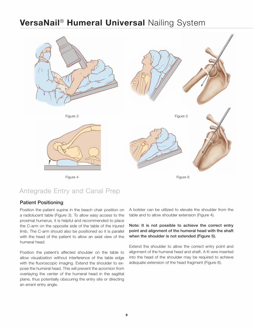
Figure 6
VersaNail® Humeral Universal Nailing System
Antegrade Entry and Canal Prep
8
Patient PositioningPosition the patient supine in the beach chair position on a radiolucent table (Figure 3). To allow easy access to the proximal humerus, it is helpful and recommended to place the C-arm on the opposite side of the table of the injured limb. The C-arm should also be positioned so it is parallel with the head of the patient to allow an axial view of the humeral head.
Position the patient’s affected shoulder on the table to allow visualization without interference of the table edge with the fluoroscopic imaging. Extend the shoulder to ex-pose the humeral head. This will prevent the acromion from overlaying the center of the humeral head in the sagittal plane, thus potentially obscuring the entry site or directing an errant entry angle.
Figure 3
Figure 4
Figure 5
A bolster can be utilized to elevate the shoulder from the table and to allow shoulder extension (Figure 4).
Note: It is not possible to achieve the correct entry point and alignment of the humeral head with the shaft when the shoulder is not extended (Figure 5).
Extend the shoulder to allow the correct entry point and alignment of the humeral head and shaft. A K-wire inserted into the head of the shoulder may be required to achieve adequate extension of the head fragment (Figure 6).
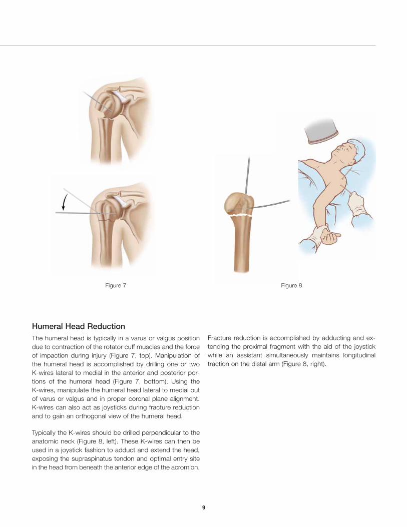
Figure 7
Humeral Head Reduction The humeral head is typically in a varus or valgus position due to contraction of the rotator cuff muscles and the force of impaction during injury (Figure 7, top). Manipulation of the humeral head is accomplished by drilling one or two K-wires lateral to medial in the anterior and posterior por-tions of the humeral head (Figure 7, bottom). Using the K-wires, manipulate the humeral head lateral to medial out of varus or valgus and in proper coronal plane alignment. K-wires can also act as joysticks during fracture reduction and to gain an orthogonal view of the humeral head.
Typically the K-wires should be drilled perpendicular to the anatomic neck (Figure 8, left). These K-wires can then be used in a joystick fashion to adduct and extend the head, exposing the supraspinatus tendon and optimal entry site in the head from beneath the anterior edge of the acromion.
Figure 8
Fracture reduction is accomplished by adducting and ex-tending the proximal fragment with the aid of the joystick while an assistant simultaneously maintains longitudinal traction on the distal arm (Figure 8, right).
9
VersaNail® Humeral Universal Nailing SystemVersaNail® Humeral Universal Nail
10
Figure 10Figure 9
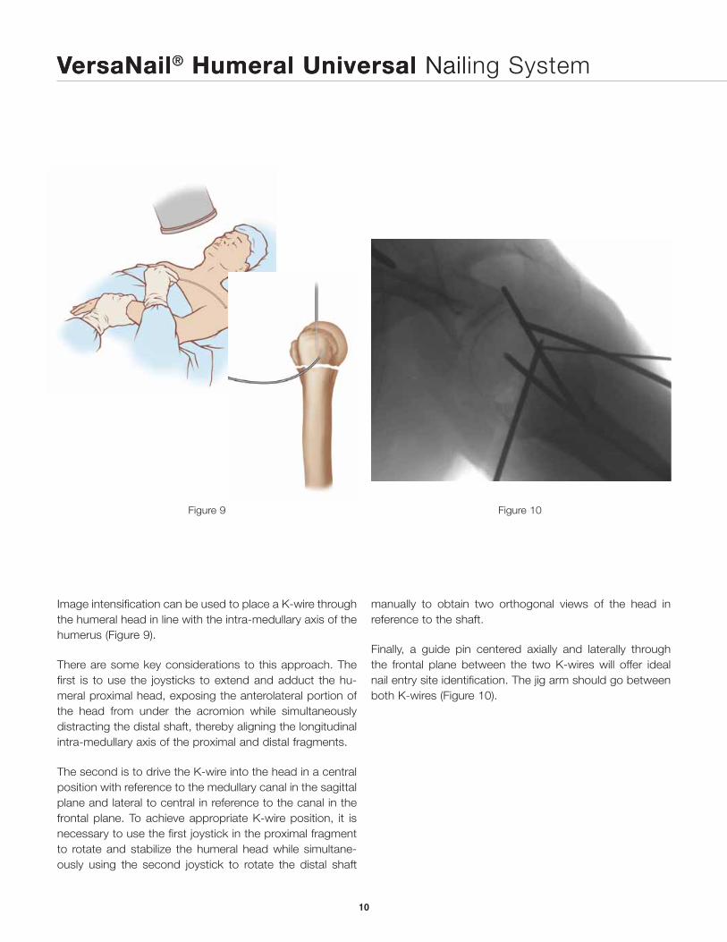
Image intensification can be used to place a K-wire through the humeral head in line with the intra-medullary axis of the humerus (Figure 9).
There are some key considerations to this approach. The first is to use the joysticks to extend and adduct the hu-meral proximal head, exposing the anterolateral portion of the head from under the acromion while simultaneously distracting the distal shaft, thereby aligning the longitudinal intra-medullary axis of the proximal and distal fragments.
The second is to drive the K-wire into the head in a central position with reference to the medullary canal in the sagittal plane and lateral to central in reference to the canal in the frontal plane. To achieve appropriate K-wire position, it is necessary to use the first joystick in the proximal fragment to rotate and stabilize the humeral head while simultane-ously using the second joystick to rotate the distal shaft
manually to obtain two orthogonal views of the head in reference to the shaft.
Finally, a guide pin centered axially and laterally through the frontal plane between the two K-wires will offer ideal nail entry site identification. The jig arm should go between both K-wires (Figure 10).
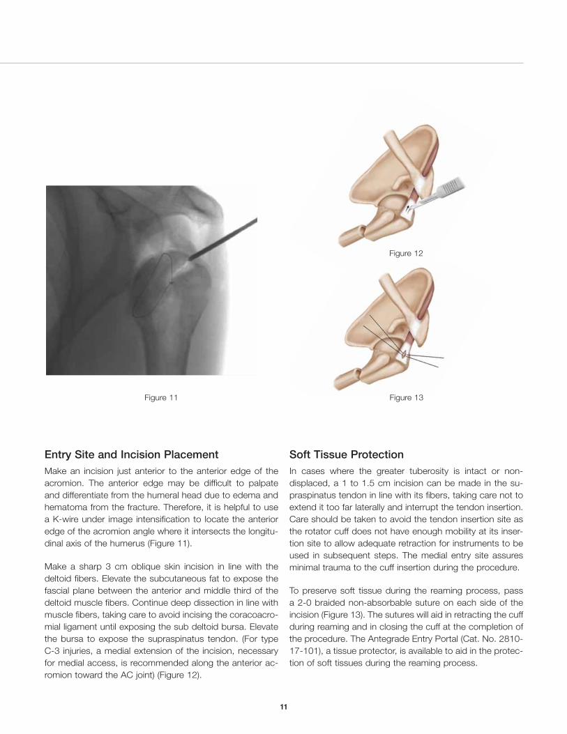
Figure 11
Figure 12
Figure 13
Entry Site and Incision Placement Make an incision just anterior to the anterior edge of the acromion. The anterior edge may be difficult to palpate and differentiate from the humeral head due to edema and hematoma from the fracture. Therefore, it is helpful to use a K-wire under image intensification to locate the anterior edge of the acromion angle where it intersects the longitu-dinal axis of the humerus (Figure 11).
Make a sharp 3 cm oblique skin incision in line with the deltoid fibers. Elevate the subcutaneous fat to expose the fascial plane between the anterior and middle third of the deltoid muscle fibers. Continue deep dissection in line with muscle fibers, taking care to avoid incising the coracoacro-mial ligament until exposing the sub deltoid bursa. Elevate the bursa to expose the supraspinatus tendon. (For type C-3 injuries, a medial extension of the incision, necessary for medial access, is recommended along the anterior ac-romion toward the AC joint) (Figure 12).
Soft Tissue Protection In cases where the greater tuberosity is intact or non-displaced, a 1 to 1.5 cm incision can be made in the su-praspinatus tendon in line with its fibers, taking care not to extend it too far laterally and interrupt the tendon insertion. Care should be taken to avoid the tendon insertion site as the rotator cuff does not have enough mobility at its inser-tion site to allow adequate retraction for instruments to be used in subsequent steps. The medial entry site assures minimal trauma to the cuff insertion during the procedure.
To preserve soft tissue during the reaming process, pass a 2-0 braided non-absorbable suture on each side of the incision (Figure 13). The sutures will aid in retracting the cuff during reaming and in closing the cuff at the completion of the procedure. The Antegrade Entry Portal (Cat. No. 2810-17-101), a tissue protector, is available to aid in the protec-tion of soft tissues during the reaming process.
11
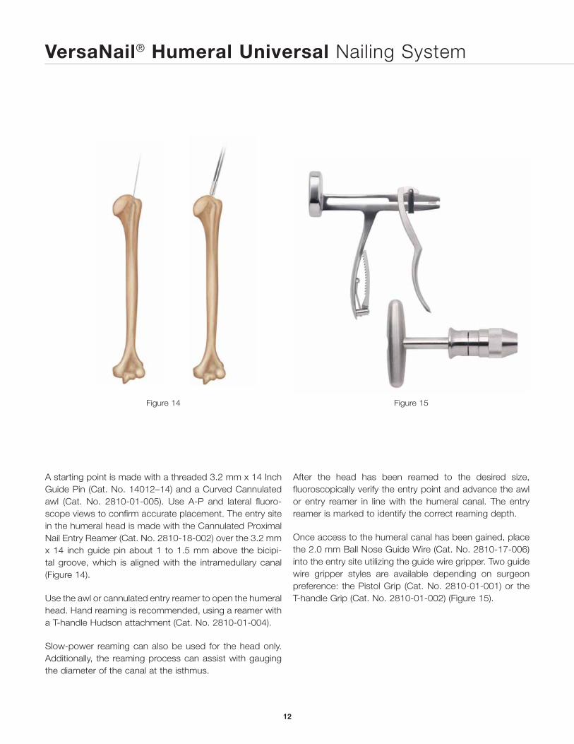
Figure 15Figure 14
A starting point is made with a threaded 3.2 mm x 14 Inch Guide Pin (Cat. No. 14012–14) and a Curved Cannulated awl (Cat. No. 2810-01-005). Use A-P and lateral fluoro-scope views to confirm accurate placement. The entry site in the humeral head is made with the Cannulated Proximal Nail Entry Reamer (Cat. No. 2810-18-002) over the 3.2 mm x 14 inch guide pin about 1 to 1.5 mm above the bicipi-tal groove, which is aligned with the intramedullary canal (Figure 14).
Use the awl or cannulated entry reamer to open the humeral head. Hand reaming is recommended, using a reamer with a T-handle Hudson attachment (Cat. No. 2810-01-004).
Slow-power reaming can also be used for the head only. Additionally, the reaming process can assist with gauging the diameter of the canal at the isthmus.
After the head has been reamed to the desired size, fluoroscopically verify the entry point and advance the awl or entry reamer in line with the humeral canal. The entry reamer is marked to identify the correct reaming depth.
Once access to the humeral canal has been gained, place the 2.0 mm Ball Nose Guide Wire (Cat. No. 2810-17-006) into the entry site utilizing the guide wire gripper. Two guide wire gripper styles are available depending on surgeon preference: the Pistol Grip (Cat. No. 2810-01-001) or the T-handle Grip (Cat. No. 2810-01-002) (Figure 15).
VersaNail® Humeral Universal Nailing System
12
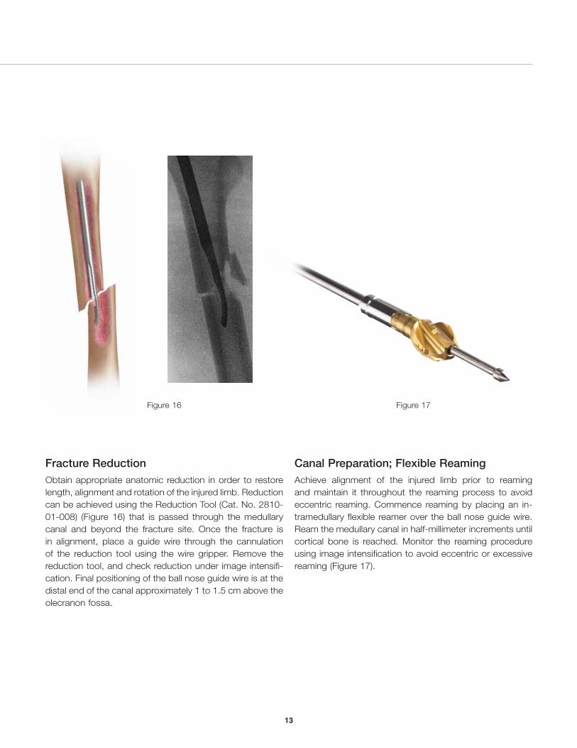
Figure 16 Figure 17
Fracture ReductionObtain appropriate anatomic reduction in order to restore length, alignment and rotation of the injured limb. Reduction can be achieved using the Reduction Tool (Cat. No. 2810-01-008) (Figure 16) that is passed through the medullary canal and beyond the fracture site. Once the fracture is in alignment, place a guide wire through the cannulation of the reduction tool using the wire gripper. Remove the reduction tool, and check reduction under image intensifi-cation. Final positioning of the ball nose guide wire is at the distal end of the canal approximately 1 to 1.5 cm above the olecranon fossa.
13
Canal Preparation; Flexible ReamingAchieve alignment of the injured limb prior to reaming and maintain it throughout the reaming process to avoid eccentric reaming. Commence reaming by placing an in-tramedullary flexible reamer over the ball nose guide wire. Ream the medullary canal in half-millimeter increments until cortical bone is reached. Monitor the reaming procedure using image intensification to avoid eccentric or excessive reaming (Figure 17).
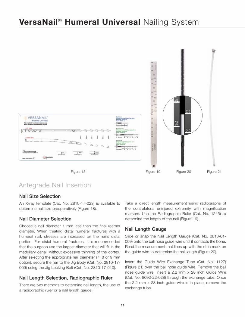
Figure 21
VersaNail® Humeral Universal Nailing System
Antegrade Nail Insertion
14
Figure 20
Nail Size SelectionAn X-ray template (Cat. No. 2810-17-023) is available to determine nail size preoperatively (Figure 18).
Nail Diameter SelectionChoose a nail diameter 1 mm less than the final reamer diameter. When treating distal humeral fractures with a humeral nail, stresses are increased on the nail’s distal portion. For distal humeral fractures, it is recommended that the surgeon use the largest diameter that will fit in the medullary canal, without excessive thinning of the cortex. After selecting the appropriate nail diameter (7, 8 or 9 mm option), secure the nail to the Jig Body (Cat. No. 2810-17-009) using the Jig Locking Bolt (Cat. No. 2810-17-010).
Nail Length Selection, Radiographic RulerThere are two methods to determine nail length, the use of a radiographic ruler or a nail length gauge.
Figure 19
Take a direct length measurement using radiographs of the contralateral uninjured extremity with magnification markers. Use the Radiographic Ruler (Cat. No. 1245) to determine the length of the nail (Figure 19).
Nail Length GaugeSlide or snap the Nail Length Gauge (Cat. No. 2810-01-009) onto the ball nose guide wire until it contacts the bone. Read the measurement that lines up with the etch mark on the guide wire to determine the nail length (Figure 20).
Insert the Guide Wire Exchange Tube (Cat. No. 1127) (Figure 21) over the ball nose guide wire. Remove the ball nose guide wire. Insert a 2.2 mm x 28 inch Guide Wire (Cat. No. 8092-22-028) through the exchange tube. Once the 2.2 mm x 28 inch guide wire is in place, remove the exchange tube.
Figure 18
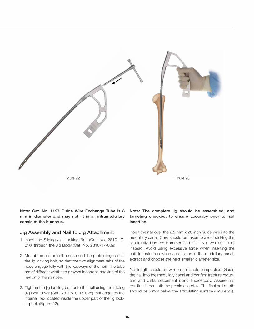
Figure 23Figure 22
Note: Cat. No. 1127 Guide Wire Exchange Tube is 8 mm in diameter and may not fit in all intramedullary canals of the humerus.
Jig Assembly and Nail to Jig Attachment1. Insert the Sliding Jig Locking Bolt (Cat. No. 2810-17-
010) through the Jig Body (Cat. No. 2810-17-009).
2. Mount the nail onto the nose and the protruding part of the jig locking bolt, so that the two alignment tabs of the nose engage fully with the keyways of the nail. The tabs are of different widths to prevent incorrect indexing of the nail onto the jig nose.
3. Tighten the jig locking bolt onto the nail using the sliding Jig Bolt Driver (Cat. No. 2810-17-028) that engages the internal hex located inside the upper part of the jig lock-ing bolt (Figure 22).
Note: The complete jig should be assembled, and targeting checked, to ensure accuracy prior to nail insertion.
Insert the nail over the 2.2 mm x 28 inch guide wire into the medullary canal. Care should be taken to avoid striking the jig directly. Use the Hammer Pad (Cat. No. 2810-01-010) instead. Avoid using excessive force when inserting the nail. In instances when a nail jams in the medullary canal, extract and choose the next smaller diameter size.
Nail length should allow room for fracture impaction. Guide the nail into the medullary canal and confirm fracture reduc-tion and distal placement using fluoroscopy. Assure nail position is beneath the proximal cortex. The final nail depth should be 5 mm below the articulating surface (Figure 23).
15
VersaNail® Humeral Universal Nailing System
Antegrade Locking
16
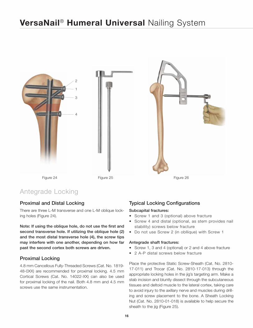
Proximal and Distal LockingThere are three L-M transverse and one L-M oblique lock-ing holes (Figure 24).
Note: If using the oblique hole, do not use the first and second transverse hole. If utilizing the oblique hole (2) and the most distal transverse hole (4), the screw tips may interfere with one another, depending on how far past the second cortex both screws are driven.
Proximal Locking4.8 mm Cancellous Fully-Threaded Screws (Cat. No. 1819-48-0XX) are recommended for proximal locking. 4.5 mm Cortical Screws (Cat. No. 14022-XX) can also be used for proximal locking of the nail. Both 4.8 mm and 4.5 mm screws use the same instrumentation.
2
1
3
4
Figure 24 Figure 25 Figure 26
Typical Locking ConfigurationsSubcapital fractures:• Screw 1 and 3 (optional) above fracture• Screw 4 and distal (optional, as stem provides nail
stability) screws below fracture• Do not use Screw 2 (in obllique) with Screw 1
Antegrade shaft fractures:• Screw 1, 3 and 4 (optional) or 2 and 4 above fracture• 2 A-P distal screws below fracture
Place the protective Static Screw-Sheath (Cat. No. 2810-17-011) and Trocar (Cat. No. 2810-17-013) through the appropriate locking holes in the jig’s targeting arm. Make a stab incision and bluntly dissect through the subcutaneous tissues and deltoid muscle to the lateral cortex, taking care to avoid injury to the axillary nerve and muscles during drill-ing and screw placement to the bone. A Sheath Locking Nut (Cat. No. 2810-01-018) is available to help secure the sheath to the jig (Figure 25).
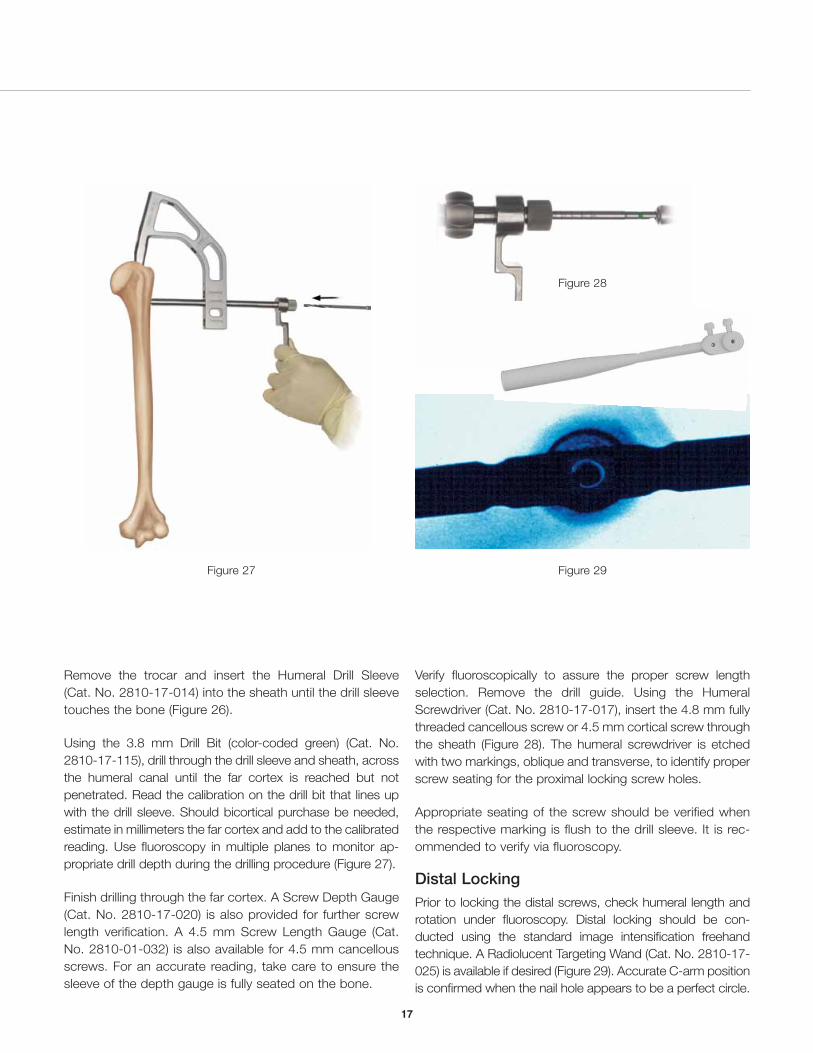
Figure 29Figure 27
Figure 28
17
Remove the trocar and insert the Humeral Drill Sleeve (Cat. No. 2810-17-014) into the sheath until the drill sleeve touches the bone (Figure 26).
Using the 3.8 mm Drill Bit (color-coded green) (Cat. No. 2810-17-115), drill through the drill sleeve and sheath, across the humeral canal until the far cortex is reached but not penetrated. Read the calibration on the drill bit that lines up with the drill sleeve. Should bicortical purchase be needed, estimate in millimeters the far cortex and add to the calibrated reading. Use fluoroscopy in multiple planes to monitor ap-propriate drill depth during the drilling procedure (Figure 27).
Finish drilling through the far cortex. A Screw Depth Gauge (Cat. No. 2810-17-020) is also provided for further screw length verification. A 4.5 mm Screw Length Gauge (Cat. No. 2810-01-032) is also available for 4.5 mm cancellous screws. For an accurate reading, take care to ensure the sleeve of the depth gauge is fully seated on the bone.
Verify fluoroscopically to assure the proper screw length selection. Remove the drill guide. Using the Humeral Screwdriver (Cat. No. 2810-17-017), insert the 4.8 mm fully threaded cancellous screw or 4.5 mm cortical screw through the sheath (Figure 28). The humeral screwdriver is etched with two markings, oblique and transverse, to identify proper screw seating for the proximal locking screw holes.
Appropriate seating of the screw should be verified when the respective marking is flush to the drill sleeve. It is rec-ommended to verify via fluoroscopy.
Distal LockingPrior to locking the distal screws, check humeral length and rotation under fluoroscopy. Distal locking should be con-ducted using the standard image intensification freehand technique. A Radiolucent Targeting Wand (Cat. No. 2810-17-025) is available if desired (Figure 29). Accurate C-arm position is confirmed when the nail hole appears to be a perfect circle.
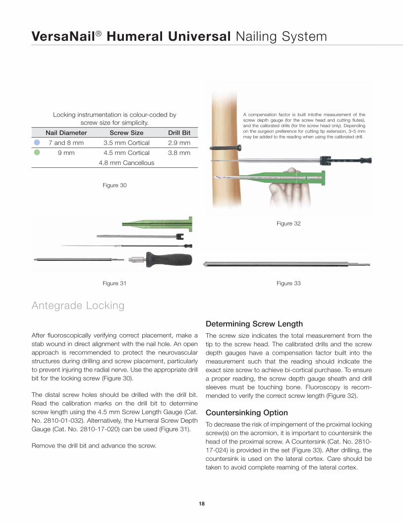
Figure 30
Figure 32
Figure 31
A compensation factor is built intothe measurement of the screw depth gauge (for the screw head and cutting flutes), and the calibrated drills (for the screw head only). Depending on the surgeon preference for cutting tip extension, 3–5 mm may be added to the reading when using the calibrated drill.
Figure 33
Locking instrumentation is colour-coded by screw size for simplicity.
Nail Diameter Screw Size Drill Bit
7 and 8 mm 3.5 mm Cortical 2.9 mm
9 mm 4.5 mm Cortical 3.8 mm
4.8 mm Cancellous
After fluoroscopically verifying correct placement, make a stab wound in direct alignment with the nail hole. An open approach is recommended to protect the neurovascular structures during drilling and screw placement, particularly to prevent injuring the radial nerve. Use the appropriate drill bit for the locking screw (Figure 30).
The distal screw holes should be drilled with the drill bit. Read the calibration marks on the drill bit to determine screw length using the 4.5 mm Screw Length Gauge (Cat. No. 2810-01-032). Alternatively, the Humeral Screw Depth Gauge (Cat. No. 2810-17-020) can be used (Figure 31).
Remove the drill bit and advance the screw.
Determining Screw LengthThe screw size indicates the total measurement from the tip to the screw head. The calibrated drills and the screw depth gauges have a compensation factor built into the measurement such that the reading should indicate the exact size screw to achieve bi-cortical purchase. To ensure a proper reading, the screw depth gauge sheath and drill sleeves must be touching bone. Fluoroscopy is recom-mended to verify the correct screw length (Figure 32).
Countersinking OptionTo decrease the risk of impingement of the proximal locking screw(s) on the acromion, it is important to countersink the head of the proximal screw. A Countersink (Cat. No. 2810-17-024) is provided in the set (Figure 33). After drilling, the countersink is used on the lateral cortex. Care should be taken to avoid complete reaming of the lateral cortex.
VersaNail® Humeral Universal Nailing System
Antegrade Locking
18
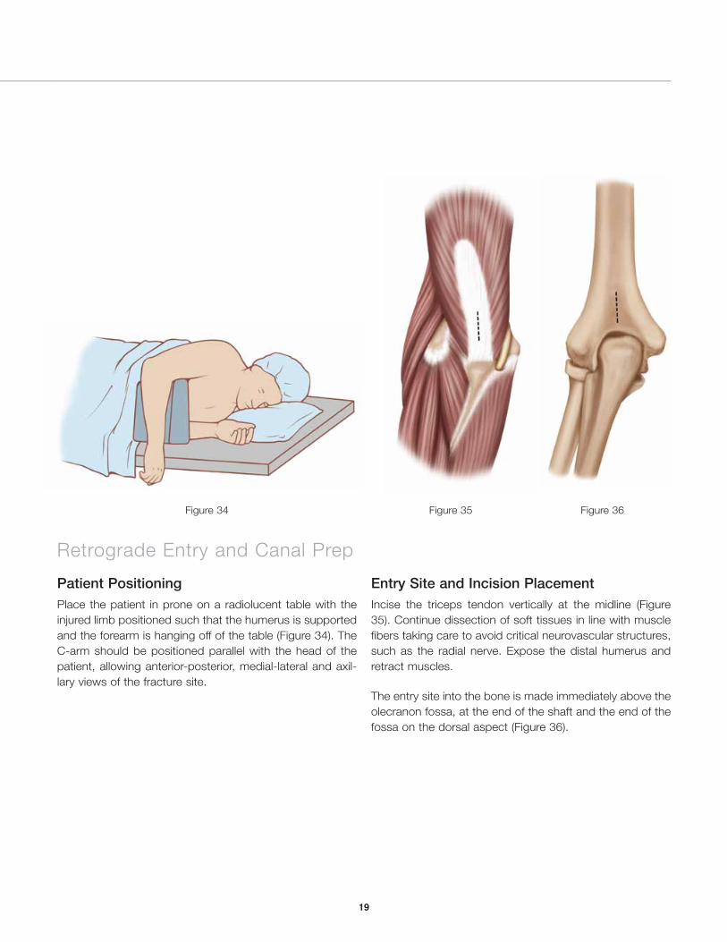
Figure 34 Figure 35 Figure 36
Patient PositioningPlace the patient in prone on a radiolucent table with the injured limb positioned such that the humerus is supported and the forearm is hanging off of the table (Figure 34). The C-arm should be positioned parallel with the head of the patient, allowing anterior-posterior, medial-lateral and axil-lary views of the fracture site.
Entry Site and Incision PlacementIncise the triceps tendon vertically at the midline (Figure 35). Continue dissection of soft tissues in line with muscle fibers taking care to avoid critical neurovascular structures, such as the radial nerve. Expose the distal humerus and retract muscles.
The entry site into the bone is made immediately above the olecranon fossa, at the end of the shaft and the end of the fossa on the dorsal aspect (Figure 36).
Retrograde Entry and Canal Prep
19
VersaNail® Humeral Universal Nailing System
Retrograde Entry and Canal Prep
20
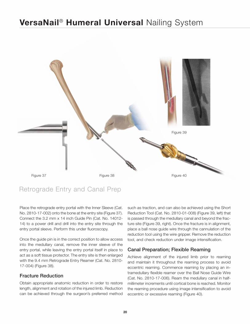
Place the retrograde entry portal with the Inner Sleeve (Cat. No. 2810-17-002) onto the bone at the entry site (Figure 37). Connect the 3.2 mm x 14 inch Guide Pin (Cat. No. 14012-14) to a power drill and drill into the entry site through the entry portal sleeve. Perform this under fluoroscopy.
Once the guide pin is in the correct position to allow access into the medullary canal, remove the inner sleeve of the entry portal, while leaving the entry portal itself in place to act as a soft tissue protector. The entry site is then enlarged with the 9.4 mm Retrograde Entry Reamer (Cat. No. 2810-17-004) (Figure 38).
Fracture ReductionObtain appropriate anatomic reduction in order to restore length, alignment and rotation of the injured limb. Reduction can be achieved through the surgeon’s preferred method
Figure 38
Figure 39
Figure 40Figure 37
such as traction, and can also be achieved using the Short Reduction Tool (Cat. No. 2810-01-008) (Figure 39, left) that is passed through the medullary canal and beyond the frac-ture site (Figure 39, right). Once the fracture is in alignment, place a ball nose guide wire through the cannulation of the reduction tool using the wire gripper. Remove the reduction tool, and check reduction under image intensification.
Canal Preparation; Flexible ReamingAchieve alignment of the injured limb prior to reaming and maintain it throughout the reaming process to avoid eccentric reaming. Commence reaming by placing an in-tramedullary flexible reamer over the Ball Nose Guide Wire (Cat. No. 2810-17-006). Ream the medullary canal in half-millimeter increments until cortical bone is reached. Monitor the reaming procedure using image intensification to avoid eccentric or excessive reaming (Figure 40).
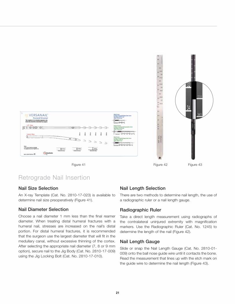
Figure 43Figure 41 Figure 42
Nail Size SelectionAn X-ray Template (Cat. No. 2810-17-023) is available to determine nail size preoperatively (Figure 41).
Nail Diameter SelectionChoose a nail diameter 1 mm less than the final reamer diameter. When treating distal humeral fractures with a humeral nail, stresses are increased on the nail’s distal portion. For distal humeral fractures, it is recommended that the surgeon use the largest diameter that will fit in the medullary canal, without excessive thinning of the cortex. After selecting the appropriate nail diameter (7, 8 or 9 mm option), secure nail to the Jig Body (Cat. No. 2810-17-009) using the Jig Locking Bolt (Cat. No. 2810-17-010).
Nail Length SelectionThere are two methods to determine nail length, the use of a radiographic ruler or a nail length gauge.
Radiographic RulerTake a direct length measurement using radiographs of the contralateral uninjured extremity with magnification markers. Use the Radiographic Ruler (Cat. No. 1245) to determine the length of the nail (Figure 42).
Nail Length GaugeSlide or snap the Nail Length Gauge (Cat. No. 2810-01-009) onto the ball nose guide wire until it contacts the bone. Read the measurement that lines up with the etch mark on the guide wire to determine the nail length (Figure 43).
Retrograde Nail Insertion
21
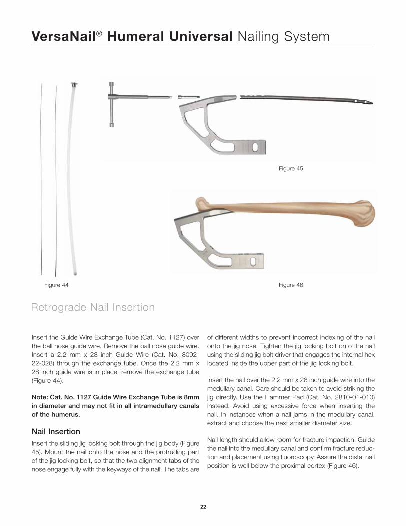
Figure 45
Figure 46Figure 44
Insert the Guide Wire Exchange Tube (Cat. No. 1127) over the ball nose guide wire. Remove the ball nose guide wire. Insert a 2.2 mm x 28 inch Guide Wire (Cat. No. 8092-22-028) through the exchange tube. Once the 2.2 mm x 28 inch guide wire is in place, remove the exchange tube (Figure 44).
Note: Cat. No. 1127 Guide Wire Exchange Tube is 8mm in diameter and may not fit in all intramedullary canals of the humerus.
Nail InsertionInsert the sliding jig locking bolt through the jig body (Figure 45). Mount the nail onto the nose and the protruding part of the jig locking bolt, so that the two alignment tabs of the nose engage fully with the keyways of the nail. The tabs are
of different widths to prevent incorrect indexing of the nail onto the jig nose. Tighten the jig locking bolt onto the nail using the sliding jig bolt driver that engages the internal hex located inside the upper part of the jig locking bolt.
Insert the nail over the 2.2 mm x 28 inch guide wire into the medullary canal. Care should be taken to avoid striking the jig directly. Use the Hammer Pad (Cat. No. 2810-01-010) instead. Avoid using excessive force when inserting the nail. In instances when a nail jams in the medullary canal, extract and choose the next smaller diameter size.
Nail length should allow room for fracture impaction. Guide the nail into the medullary canal and confirm fracture reduc-tion and placement using fluoroscopy. Assure the distal nail position is well below the proximal cortex (Figure 46).
VersaNail® Humeral Universal Nailing System
Retrograde Nail Insertion
22
1
2
3
4
Figure 47 Figure 48 Figure 49
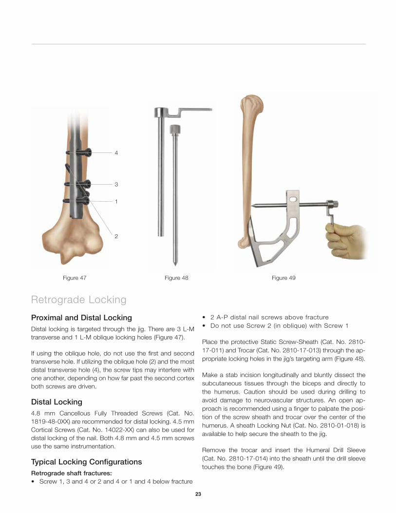
Proximal and Distal LockingDistal locking is targeted through the jig. There are 3 L-M transverse and 1 L-M oblique locking holes (Figure 47).
If using the oblique hole, do not use the first and second transverse hole. If utilizing the oblique hole (2) and the most distal transverse hole (4), the screw tips may interfere with one another, depending on how far past the second cortex both screws are driven.
Distal Locking4.8 mm Cancellous Fully Threaded Screws (Cat. No. 1819-48-0XX) are recommended for distal locking. 4.5 mm Cortical Screws (Cat. No. 14022-XX) can also be used for distal locking of the nail. Both 4.8 mm and 4.5 mm screws use the same instrumentation.
Typical Locking ConfigurationsRetrograde shaft fractures:• Screw 1, 3 and 4 or 2 and 4 or 1 and 4 below fracture
• 2 A-P distal nail screws above fracture• Do not use Screw 2 (in oblique) with Screw 1
Place the protective Static Screw-Sheath (Cat. No. 2810-17-011) and Trocar (Cat. No. 2810-17-013) through the ap-propriate locking holes in the jig’s targeting arm (Figure 48).
Make a stab incision longitudinally and bluntly dissect the subcutaneous tissues through the biceps and directly to the humerus. Caution should be used during drilling to avoid damage to neurovascular structures. An open ap-proach is recommended using a finger to palpate the posi-tion of the screw sheath and trocar over the center of the humerus. A sheath Locking Nut (Cat. No. 2810-01-018) is available to help secure the sheath to the jig.
Remove the trocar and insert the Humeral Drill Sleeve (Cat. No. 2810-17-014) into the sheath until the drill sleeve touches the bone (Figure 49).
Retrograde Locking
23
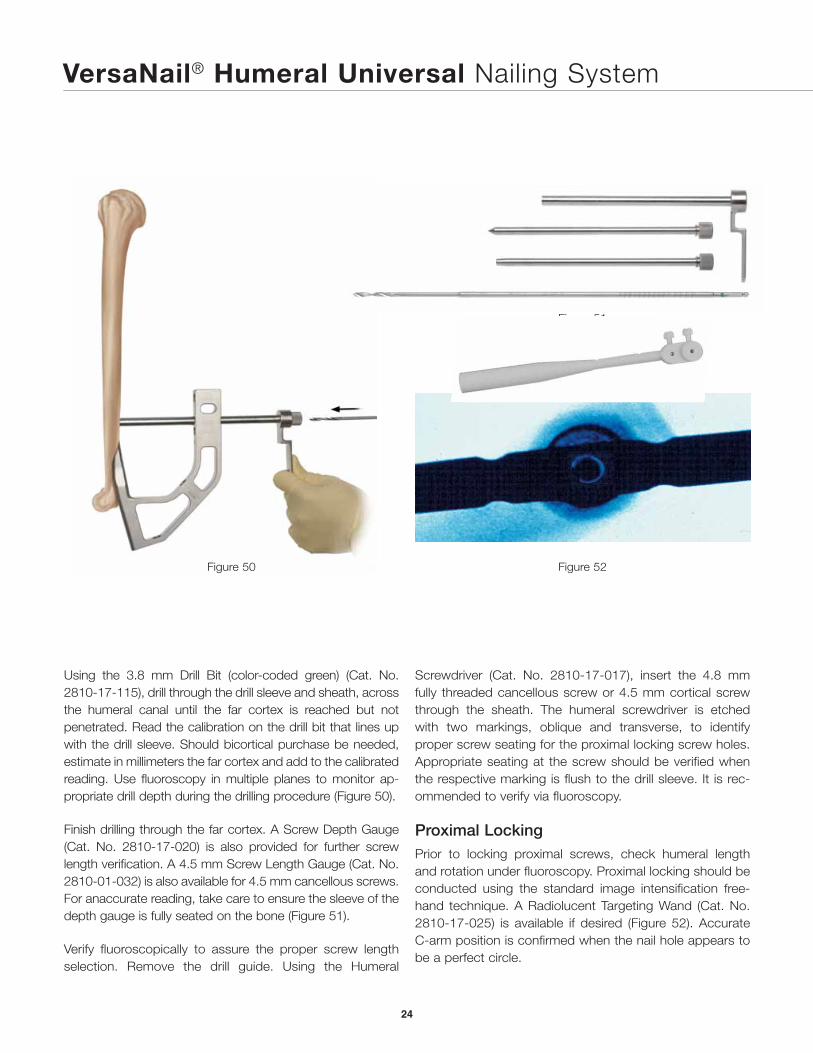
Using the 3.8 mm Drill Bit (color-coded green) (Cat. No. 2810-17-115), drill through the drill sleeve and sheath, across the humeral canal until the far cortex is reached but not penetrated. Read the calibration on the drill bit that lines up with the drill sleeve. Should bicortical purchase be needed, estimate in millimeters the far cortex and add to the calibrated reading. Use fluoroscopy in multiple planes to monitor ap-propriate drill depth during the drilling procedure (Figure 50).
Finish drilling through the far cortex. A Screw Depth Gauge (Cat. No. 2810-17-020) is also provided for further screw length verification. A 4.5 mm Screw Length Gauge (Cat. No. 2810-01-032) is also available for 4.5 mm cancellous screws. For anaccurate reading, take care to ensure the sleeve of the depth gauge is fully seated on the bone (Figure 51).
Verify fluoroscopically to assure the proper screw length selection. Remove the drill guide. Using the Humeral
Figure 52
Figure 51
Figure 50
Screwdriver (Cat. No. 2810-17-017), insert the 4.8 mm fully threaded cancellous screw or 4.5 mm cortical screw through the sheath. The humeral screwdriver is etched with two markings, oblique and transverse, to identify proper screw seating for the proximal locking screw holes. Appropriate seating at the screw should be verified when the respective marking is flush to the drill sleeve. It is rec-ommended to verify via fluoroscopy.
Proximal LockingPrior to locking proximal screws, check humeral length and rotation under fluoroscopy. Proximal locking should be conducted using the standard image intensification free-hand technique. A Radiolucent Targeting Wand (Cat. No. 2810-17-025) is available if desired (Figure 52). Accurate C-arm position is confirmed when the nail hole appears to be a perfect circle.
VersaNail® Humeral Universal Nailing System
24
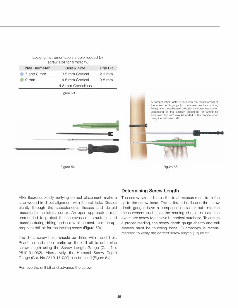
Figure 54
After fluoroscopically verifying correct placement, make a stab wound in direct alignment with the nail hole. Dissect bluntly through the subcutaneous tissues and deltoid muscles to the lateral cortex. An open approach is rec-ommended to protect the neurovascular structures and muscles during drilling and screw placement. Use the ap-propriate drill bit for the locking screw (Figure 53).
The distal screw holes should be drilled with the drill bit. Read the calibration marks on the drill bit to determine screw length using the Screw Length Gauge (Cat. No. 2810-01-032). Alternatively, the Humeral Screw Depth Gauge (Cat. No.2810-17-020) can be used (Figure 54).
Remove the drill bit and advance the screw.
Figure 55
A compensation factor is built into the measurement of the screw depth gauge (for the screw head and cutting flutes), and the calibrated drills (for the screw head only). Depending on the surgeon preference for cutting tip extension, 3–5 mm may be added to the reading when using the calibrated drill.
Locking instrumentation is color-coded by screw size for simplicity.
Nail Diameter Screw Size Drill Bit
7 and 8 mm 3.5 mm Cortical 2.9 mm
9 mm 4.5 mm Cortical 3.8 mm
4.8 mm Cancellous
Figure 53
Determining Screw LengthThe screw size indicates the total measurement from the tip to the screw head. The calibrated drills and the screw depth gauges have a compensation factor built into the measurement such that the reading should indicate the exact size screw to achieve bi-cortical purchase. To ensure a proper reading, the screw depth gauge sheath and drill sleeves must be touching bone. Fluoroscopy is recom-mended to verify the correct screw length (Figure 55).
25
VersaNail® Humeral Universal Nailing System
Figure 57
26
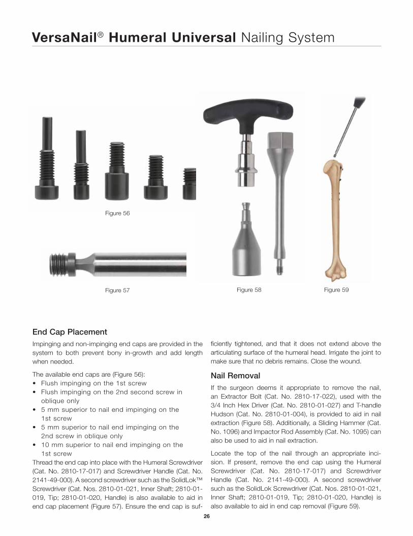
End Cap PlacementImpinging and non-impinging end caps are provided in the system to both prevent bony in-growth and add length when needed. The available end caps are (Figure 56):• Flush impinging on the 1st screw• Flush impinging on the 2nd second screw in
oblique only• 5 mm superior to nail end impinging on the
1st screw• 5 mm superior to nail end impinging on the
2nd screw in oblique only• 10 mm superior to nail end impinging on the
1st screwThread the end cap into place with the Humeral Screwdriver (Cat. No. 2810-17-017) and Screwdriver Handle (Cat. No. 2141-49-000). A second screwdriver such as the SolidLok™ Screwdriver (Cat. Nos. 2810-01-021, Inner Shaft; 2810-01-019, Tip; 2810-01-020, Handle) is also available to aid in end cap placement (Figure 57). Ensure the end cap is suf-
Figure 56
Figure 58 Figure 59
ficiently tightened, and that it does not extend above the articulating surface of the humeral head. Irrigate the joint to make sure that no debris remains. Close the wound.
Nail RemovalIf the surgeon deems it appropriate to remove the nail, an Extractor Bolt (Cat. No. 2810-17-022), used with the 3/4 Inch Hex Driver (Cat. No. 2810-01-027) and T-handle Hudson (Cat. No. 2810-01-004), is provided to aid in nail extraction (Figure 58). Additionally, a Sliding Hammer (Cat. No. 1096) and Impactor Rod Assembly (Cat. No. 1095) can also be used to aid in nail extraction.
Locate the top of the nail through an appropriate inci-sion. If present, remove the end cap using the Humeral Screwdriver (Cat. No. 2810-17-017) and Screwdriver Handle (Cat. No. 2141-49-000). A second screwdriver such as the SolidLok Screwdriver (Cat. Nos. 2810-01-021, Inner Shaft; 2810-01-019, Tip; 2810-01-020, Handle) is also available to aid in end cap removal (Figure 59).
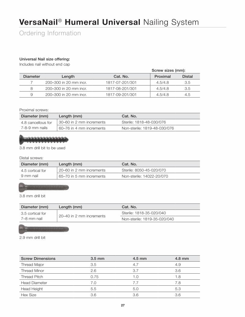
Universal Nail size offering: Includes nail without end cap
Screw sizes (mm):
Diameter Length Cat. No. Proximal Distal
7 200–300 in 20 mm incr. 1817-07-201/301 4.5/4.8 3.5
8 200–300 in 20 mm incr. 1817-08-201/301 4.5/4.8 3.5
9 200–300 in 20 mm incr. 1817-09-201/301 4.5/4.8 4.5
Proximal screws:
Diameter (mm) Length (mm) Cat. No.
4.8 cancellous for 7-8-9 mm nails
30–60 in 2 mm increments Sterile: 1818-48-030/076
60–76 in 4 mm increments Non-sterile: 1819-48-030/076
3.8 mm drill bit to be used
Distal screws:
Diameter (mm) Length (mm) Cat. No.
4.5 cortical for 9 mm nail
20–60 in 2 mm increments Sterile: 8050-45-020/070
65–70 in 5 mm increments Non-sterile: 14022-20/070
3.8 mm drill bit
Diameter (mm) Length (mm) Cat. No.
3.5 cortical for 7–8 mm nail
20–40 in 2 mm incrementsSterile: 1818-35-020/040
Non-sterile: 1819-35-020/040
2.9 mm drill bit
Screw Dimensions 3.5 mm 4.5 mm 4.8 mm
Thread Major 3.5 4.7 4.9
Thread Minor 2.6 3.7 3.6
Thread Pitch 0.75 1.0 1.8
Head Diameter 7.0 7.7 7.8
Head Height 5.5 5.0 5.3
Hex Size 3.6 3.6 3.6
VersaNail® Humeral Universal Nailing SystemOrdering Information
27
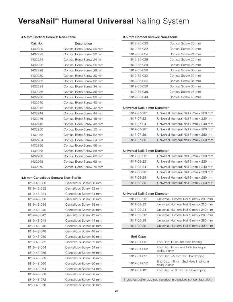
4.5 mm Cortical Screws: Non-Sterile
Cat. No. Description
1402220 Cortical Bone Screw 20 mm
1402222 Cortical Bone Screw 22 mm
1402224 Cortical Bone Screw 24 mm
1402226 Cortical Bone Screw 26 mm
1402228 Cortical Bone Screw 28 mm
1402230 Cortical Bone Screw 30 mm
1402232 Cortical Bone Screw 32 mm
1402234 Cortical Bone Screw 34 mm
1402236 Cortical Bone Screw 36 mm
1402238 Cortical Bone Screw 38 mm
1402240 Cortical Bone Screw 40 mm
1402242 Cortical Bone Screw 42 mm
1402244 Cortical Bone Screw 44 mm
1402246 Cortical Bone Screw 46 mm
1402248 Cortical Bone Screw 48 mm
1402250 Cortical Bone Screw 50 mm
1402252 Cortical Bone Screw 52 mm
1402254 Cortical Bone Screw 54 mm
1402256 Cortical Bone Screw 56 mm
1402258 Cortical Bone Screw 58 mm
1402260 Cortical Bone Screw 60 mm
1402265 Cortical Bone Screw 65 mm
1402270 Cortical Bone Screw 70 mm
4.8 mm Cancellous Screws: Non-Sterile
1819-48-030 Cancellous Screw 30 mm
1819-48-032 Cancellous Screw 32 mm
1819-48-034 Cancellous Screw 34 mm
1819-48-036 Cancellous Screw 36 mm
1819-48-038 Cancellous Screw 38 mm
1819-48-040 Cancellous Screw 40 mm
1819-48-042 Cancellous Screw 42 mm
1819-48-044 Cancellous Screw 44 mm
1819-48-046 Cancellous Screw 46 mm
1819-48-048 Cancellous Screw 48 mm
1819-48-050 Cancellous Screw 50 mm
1819-48-052 Cancellous Screw 52 mm
1819-48-054 Cancellous Screw 54 mm
1819-48-056 Cancellous Screw 56 mm
1819-48-058 Cancellous Screw 58 mm
1819-48-060 Cancellous Screw 60 mm
1819-48-064 Cancellous Screw 64 mm
1819-48-068 Cancellous Screw 68 mm
1819-48-072 Cancellous Screw 72 mm
1819-48-076 Cancellous Screw 76 mm
3.5 mm Cortical Screws: Non-Sterile
1819-35-020 Cortical Screw 20 mm
1819-35-022 Cortical Screw 22 mm
1819-35-024 Cortical Screw 24 mm
1819-35-026 Cortical Screw 26 mm
1819-35-028 Cortical Screw 28 mm
1819-35-030 Cortical Screw 30 mm
1819-35-032 Cortical Screw 32 mm
1819-35-034 Cortical Screw 34 mm
1819-35-036 Cortical Screw 36 mm
1819-35-038 Cortical Screw 38 mm
1819-35-040 Cortical Screw 40 mm
Universal Nail: 7 mm Diameter
1817-07-201 Universal Humeral Nail 7 mm x 200 mm
1817-07-221 Universal Humeral Nail 7 mm x 220 mm
1817-07-241 Universal Humeral Nail 7 mm x 240 mm
1817-07-261 Universal Humeral Nail 7 mm x 260 mm
1817-07-281 Universal Humeral Nail 7 mm x 280 mm
1817-07-301 Universal Humeral Nail 7 mm x 300 mm
Universal Nail: 8 mm Diameter
1817-08-201 Universal Humeral Nail 8 mm x 200 mm
1817-08-221 Universal Humeral Nail 8 mm x 220 mm
1817-08-241 Universal Humeral Nail 8 mm x 240 mm
1817-08-261 Universal Humeral Nail 8 mm x 260 mm
1817-08-281 Universal Humeral Nail 8 mm x 280 mm
1817-08-301 Universal Humeral Nail 8 mm x 300 mm
Universal Nail: 9 mm Diameter
1817-09-201 Universal Humeral Nail 9 mm x 200 mm
1817-09-221 Universal Humeral Nail 9 mm x 220 mm
1817-09-241 Universal Humeral Nail 9 mm x 240 mm
1817-09-261 Universal Humeral Nail 9 mm x 260 mm
1817-09-281 Universal Humeral Nail 9 mm x 280 mm
1817-09-301 Universal Humeral Nail 9 mm x 300 mm
End Caps
1817-01-001 End Cap, Flush 1st Hole Imping
1817-01-002 End Cap, Flush 2nd Hole Imping in oblique only
1817-01-051 End Cap, +5 mm 1st Hole Imping
1817-01-052 End Cap, +5 mm 2nd Hole Imping in oblique only
1817-01-101 End Cap, +10 mm 1st Hole Imping
Indicates outlier size not included in standard set configuration.
VersaNail® Humeral Universal Nailing System
28
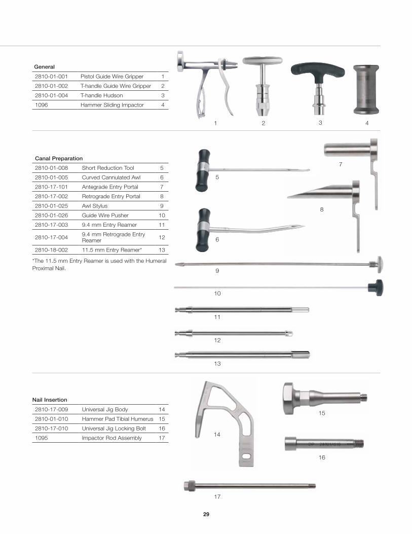
General
2810-01-001 Pistol Guide Wire Gripper 1
2810-01-002 T-handle Guide Wire Gripper 2
2810-01-004 T-handle Hudson 3
1096 Hammer Sliding Impactor 4
Canal Preparation
2810-01-008 Short Reduction Tool 5
2810-01-005 Curved Cannulated Awl 6
2810-17-101 Antegrade Entry Portal 7
2810-17-002 Retrograde Entry Portal 8
2810-01-025 Awl Stylus 9
2810-01-026 Guide Wire Pusher 10
2810-17-003 9.4 mm Entry Reamer 11
2810-17-004 9.4 mm Retrograde Entry Reamer 12
2810-18-002 11.5 mm Entry Reamer* 13
*The 11.5 mm Entry Reamer is used with the Humeral Proximal Nail.
Nail Insertion
2810-17-009 Universal Jig Body 14
2810-01-010 Hammer Pad Tibial Humerus 15
2810-17-010 Universal Jig Locking Bolt 16
1095 Impactor Rod Assembly 17
1 2
9
10
17
3
14
15
7
8
5
6
11
12
13
16
4
29
26
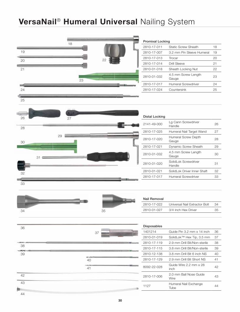
Promixal Locking
2810-17-011 Static Screw Sheath 18
2810-17-007 3.2 mm Pin Sleeve Humeral 19
2810-17-013 Trocar 20
2810-17-014 Drill Sleeve 21
2810-01-018 Sheath Locking Nut 22
2810-01-032 4.5 mm Screw Length Gauge
23
2810-17-017 Humeral Screwdriver 24
2810-17-024 Countersink 25
Distal Locking
2141-49-000 Lg Cann Screwdriver Handle
26
2810-17-025 Humeral Nail Target Wand 27
2810-17-020 Humeral Screw Depth Gauge
28
2810-17-021 Dynamic Screw Sheath 29
2810-01-032 4.5 mm Screw Length Gauge
30
2810-01-020 SolidLok Screwdriver Handle
31
2810-01-021 SolidLok Driver Inner Shaft 32
2810-17-017 Humeral Screwdriver 33
Nail Removal
2810-17-022 Universal Nail Extractor Bolt 34
2810-01-027 3/4 inch Hex Driver 35
Disposables
1401214 Guide Pin 3.2 mm x 14 inch 36
2810-01-019 SolidLok™ Hex Tip, 3.5 mm 37
2810-17-119 2.9 mm Drill Bit/Non-sterile 38
2810-17-115 3.8 mm Drill Bit/Non-sterile 39
2810-12-138 3.8 mm Drill Bit 6 inch NS 40
2810-17-129 2.9 mm Drill Bit Short NS 41
8092-22-028 Guide Wire 2.2 mm x 28 inch
42
2810-17-006 2.0 mm Ball Nose Guide Wire
43
1127 Humeral Nail Exchange Tube
44
18
22
24
25
23
27
28
32
33
31
19
20
21
34
36
38
39
40
41
42
43
44
37
35
29
30
VersaNail® Humeral Universal Nailing System
30
47Module
48Outer Case
51
53
54
55
45
46
49
50
52
31
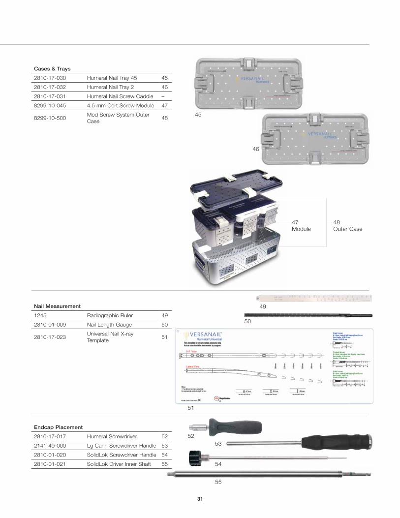
Cases & Trays
2810-17-030 Humeral Nail Tray 45 45
2810-17-032 Humeral Nail Tray 2 46
2810-17-031 Humeral Nail Screw Caddie –
8299-10-045 4.5 mm Cort Screw Module 47
8299-10-500 Mod Screw System Outer Case
48
Nail Measurement
1245 Radiographic Ruler 49
2810-01-009 Nail Length Gauge 50
2810-17-023 Universal Nail X-ray Template
51
Endcap Placement
2810-17-017 Humeral Screwdriver 52
2141-49-000 Lg Cann Screwdriver Handle 53
2810-01-020 SolidLok Screwdriver Handle 54
2810-01-021 SolidLok Driver Inner Shaft 55
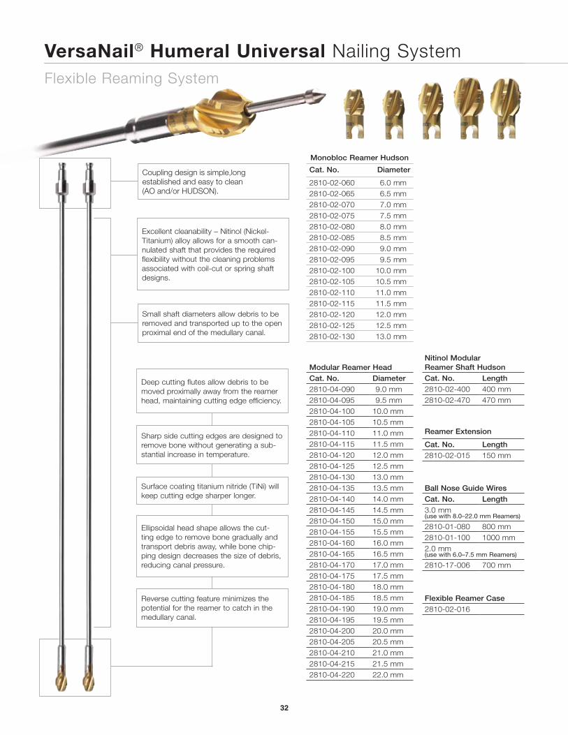
VersaNail® Humeral Universal Nailing SystemFlexible Reaming System
32
Monobloc Reamer Hudson
Cat. No. Diameter
2810-02-060 6.0 mm2810-02-065 6.5 mm2810-02-070 7.0 mm2810-02-075 7.5 mm2810-02-080 8.0 mm2810-02-085 8.5 mm2810-02-090 9.0 mm2810-02-095 9.5 mm2810-02-100 10.0 mm2810-02-105 10.5 mm2810-02-110 11.0 mm2810-02-115 11.5 mm2810-02-120 12.0 mm2810-02-125 12.5 mm2810-02-130 13.0 mm
Modular Reamer HeadCat. No. Diameter2810-04-090 9.0 mm2810-04-095 9.5 mm2810-04-100 10.0 mm2810-04-105 10.5 mm2810-04-110 11.0 mm2810-04-115 11.5 mm2810-04-120 12.0 mm2810-04-125 12.5 mm2810-04-130 13.0 mm2810-04-135 13.5 mm2810-04-140 14.0 mm2810-04-145 14.5 mm2810-04-150 15.0 mm2810-04-155 15.5 mm2810-04-160 16.0 mm2810-04-165 16.5 mm2810-04-170 17.0 mm2810-04-175 17.5 mm2810-04-180 18.0 mm2810-04-185 18.5 mm2810-04-190 19.0 mm2810-04-195 19.5 mm2810-04-200 20.0 mm2810-04-205 20.5 mm2810-04-210 21.0 mm2810-04-215 21.5 mm2810-04-220 22.0 mm
Nitinol Modular Reamer Shaft HudsonCat. No. Length2810-02-400 400 mm2810-02-470 470 mm
Reamer Extension
Cat. No. Length2810-02-015 150 mm
Ball Nose Guide WiresCat. No. Length3.0 mm(use with 8.0–22.0 mm Reamers)
2810-01-080 800 mm2810-01-100 1000 mm2.0 mm(use with 6.0–7.5 mm Reamers)
2810-17-006 700 mm
Flexible Reamer Case2810-02-016
Small shaft diameters allow debris to be removed and transported up to the open proximal end of the medullary canal.
Excellent cleanability – Nitinol (Nickel-Titanium) alloy allows for a smooth can-nulated shaft that provides the required flexibility without the cleaning problems associated with coil-cut or spring shaft designs.
Deep cutting flutes allow debris to be moved proximally away from the reamer head, maintaining cutting edge efficiency.
Sharp side cutting edges are designed to remove bone without generating a sub-stantial increase in temperature.
Surface coating titanium nitride (TiNi) will keep cutting edge sharper longer.
Ellipsoidal head shape allows the cut-ting edge to remove bone gradually and transport debris away, while bone chip-ping design decreases the size of debris, reducing canal pressure.
Reverse cutting feature minimizes the potential for the reamer to catch in the medullary canal.
Coupling design is simple,long established and easy to clean (AO and/or HUDSON).
33
25.5 mm
51.5 mm
Proximal End2.5º
45º
13.5 mm
Proximal End 9.2 mm
Distal End
0 mm
17 mm
28 mm
39 mm
60 mm
3 mm Cannulation4º
Locking Options
Screws, Plates, Intramedullary Nails, Compression Hip Screws, Pins and Wires
Important:
This Essential Product Information does not include all of the information necessary for selection and use of a device. Please see full labeling for all necessary information.
Indications:
The use of metallic surgical appliances (screws, plates, intramedullary nails, compression hip screws, pins and wires) provides the orthopaedic surgeon a means of bone fixation and helps generally in the management of fractures and reconstructive surgeries. These implants are intended as a guide to normal healing, and are NOT intended to replace normal body structure or bear the weight of the body in the presence of incomplete bone healing. Delayed unions or nonunions in the presence of load bearing or weight bearing might eventually cause the implant to break due to metal fatigue. All metal surgical implants are subjected to repeated stress in use, which can result in metal fatigue.
Contraindications:
Screws, plates, intramedullary nails, compression hip screws, pins and wires are contraindicated in: active infection, conditions which tend to retard healing such as blood supply limitations, previous infections, insufficient quantity or quality of bone to permit stabilization of the fracture complex, conditions that restrict the patient’s ability or willingness to follow postoperative instructions during the healing process, foreign body sensitivity, and cases where the implant(s) would cross open epiphyseal plates in skeletally immature patients.
Additional Contraindication for Orthopaedic Screws and Plates only:
Cases with malignant primary or metastatic tumors which preclude adequate bone support or screw fixations, unless supplemental fixation or stabilization methods are utilized.
Additional Contraindication for Retrograde Femoral Nailing:
A history of septic arthritis of the knee and knee extension contracture with inability to attain at least 45º of flexion.
Additional Contraindications for Compression Hip Screws only:
Inadequate implant support due to the lack of medial buttress.
Warnings and Precautions:
Bone screws and pins are intended for partial weight bearing and non-weight bearing applications. These components cannot be expected to withstand the unsupported stresses of full weight bearing.
Adverse Events:
The following are the most frequent adverse events after fixation with orthopaedic screws, plates, intramedullary nails, compression hip screws, pins and wires: loosening, bending, cracking or fracture of the components or loss of fixation in bone attributable to nonunion, osteoporosis, markedly unstable comminuted fractures; loss of anatomic position with nonunion or malunion with rotation or angulation; infection and allergies and adverse reactions to the device material. Surgeons should take care when targeting and drilling for the proximal screws in any tibial nail with oblique proximal screws. Care should be taken as the drill bit is advanced to penetrate the far cortex. Advancing the drill bit too far in this area may cause injury to the deep peroneal nerve. Fluoroscopy should be used to verify correct positioning of the drill bit.
Additional Adverse Events for Compression Hip Screw only:
Screw cutout of the femoral head (usually associated with osteoporotic bone).
All trademarks herein are the property of Biomet, Inc. or its subsidiaries unless otherwise indicated.
This material is intended for the sole use and benefit of the Biomet sales force and physicians. It is not to be redistributed, duplicated or disclosed without the express written consent of Biomet.
For product information, including indications, contraindications, warnings, precau-tions and potential adverse effects, see the package insert.
P.O. Box 587, Warsaw, IN 46581-0587 • 800.348.9500 x 1501 ©2012 Biomet Orthopedics • biomet.com
Form No. BMET0083.0 • REV091512