Embed Size (px)
Citation preview

VersaView 5000 ThinManager Thin Clients and Industrial ComputersCatalog Numbers 6200P, 6200T, 6200V
User ManualOriginal Instructions

Important User Information
Read this document and the documents listed in the additional resources section about installation, configuration, and operation of this equipment before you install, configure, operate, or maintain this product. Users are required to familiarize themselves with installation and wiring instructions in addition to requirements of all applicable codes, laws, and standards.
Activities including installation, adjustments, putting into service, use, assembly, disassembly, and maintenance are required to be carried out by suitably trained personnel in accordance with applicable code of practice.
If this equipment is used in a manner not specified by the manufacturer, the protection provided by the equipment may be impaired.
In no event will Rockwell Automation, Inc. be responsible or liable for indirect or consequential damages resulting from the use or application of this equipment.
The examples and diagrams in this manual are included solely for illustrative purposes. Because of the many variables and requirements associated with any particular installation, Rockwell Automation, Inc. cannot assume responsibility or liability for actual use based on the examples and diagrams.
No patent liability is assumed by Rockwell Automation, Inc. with respect to use of information, circuits, equipment, or software described in this manual.
Reproduction of the contents of this manual, in whole or in part, without written permission of Rockwell Automation, Inc., is prohibited.
Throughout this manual, when necessary, we use notes to make you aware of safety considerations.
Labels may also be on or inside the equipment to provide specific precautions.
WARNING: Identifies information about practices or circumstances that can cause an explosion in a hazardous environment, which may lead to personal injury or death, property damage, or economic loss.
ATTENTION: Identifies information about practices or circumstances that can lead to personal injury or death, property damage, or economic loss. Attentions help you identify a hazard, avoid a hazard, and recognize the consequence.
IMPORTANT Identifies information that is critical for successful application and understanding of the product.
SHOCK HAZARD: Labels may be on or inside the equipment, for example, a drive or motor, to alert people that dangerous voltage may be present.
BURN HAZARD: Labels may be on or inside the equipment, for example, a drive or motor, to alert people that surfaces may reach dangerous temperatures.
ARC FLASH HAZARD: Labels may be on or inside the equipment, for example, a motor control center, to alert people to potential Arc Flash. Arc Flash will cause severe injury or death. Wear proper Personal Protective Equipment (PPE). Follow ALL Regulatory requirements for safe work practices and for Personal Protective Equipment (PPE).
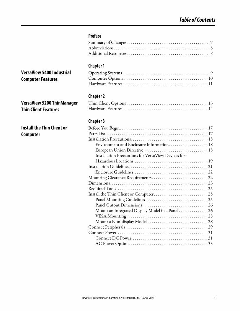
Table of Contents
PrefaceSummary of Changes . . . . . . . . . . . . . . . . . . . . . . . . . . . . . . . . . . . . . . . . . . . 7Abbreviations . . . . . . . . . . . . . . . . . . . . . . . . . . . . . . . . . . . . . . . . . . . . . . . . . . 8Additional Resources . . . . . . . . . . . . . . . . . . . . . . . . . . . . . . . . . . . . . . . . . . . 8
Chapter 1VersaView 5400 Industrial Computer Features
Operating Systems . . . . . . . . . . . . . . . . . . . . . . . . . . . . . . . . . . . . . . . . . . . . . 9Computer Options . . . . . . . . . . . . . . . . . . . . . . . . . . . . . . . . . . . . . . . . . . . . 10Hardware Features . . . . . . . . . . . . . . . . . . . . . . . . . . . . . . . . . . . . . . . . . . . . 11
Chapter 2VersaView 5200 ThinManager Thin Client Features
Thin Client Options . . . . . . . . . . . . . . . . . . . . . . . . . . . . . . . . . . . . . . . . . . 13Hardware Features . . . . . . . . . . . . . . . . . . . . . . . . . . . . . . . . . . . . . . . . . . . . 14
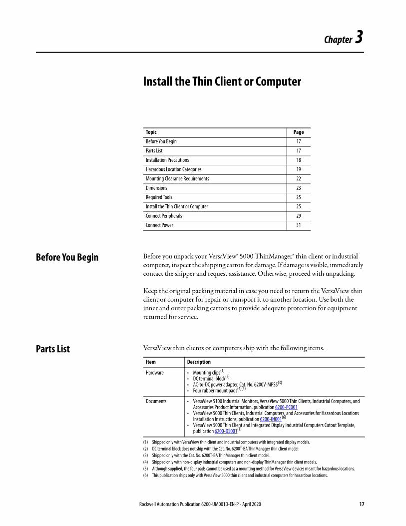
Chapter 3Install the Thin Client or Computer
Before You Begin. . . . . . . . . . . . . . . . . . . . . . . . . . . . . . . . . . . . . . . . . . . . . . 17Parts List . . . . . . . . . . . . . . . . . . . . . . . . . . . . . . . . . . . . . . . . . . . . . . . . . . . . . 17Installation Precautions. . . . . . . . . . . . . . . . . . . . . . . . . . . . . . . . . . . . . . . . 18
Environment and Enclosure Information . . . . . . . . . . . . . . . . . . . . 18European Union Directive . . . . . . . . . . . . . . . . . . . . . . . . . . . . . . . . . 18Installation Precautions for VersaView Devices for Hazardous Locations . . . . . . . . . . . . . . . . . . . . . . . . . . . . . . . . . . . . . . 19
Installation Guidelines. . . . . . . . . . . . . . . . . . . . . . . . . . . . . . . . . . . . . . . . . 21Enclosure Guidelines . . . . . . . . . . . . . . . . . . . . . . . . . . . . . . . . . . . . . . 22
Mounting Clearance Requirements . . . . . . . . . . . . . . . . . . . . . . . . . . . . . 22Dimensions . . . . . . . . . . . . . . . . . . . . . . . . . . . . . . . . . . . . . . . . . . . . . . . . . . . 23Required Tools . . . . . . . . . . . . . . . . . . . . . . . . . . . . . . . . . . . . . . . . . . . . . . . 25Install the Thin Client or Computer . . . . . . . . . . . . . . . . . . . . . . . . . . . . 25
Panel Mounting Guidelines . . . . . . . . . . . . . . . . . . . . . . . . . . . . . . . . 25Panel Cutout Dimensions . . . . . . . . . . . . . . . . . . . . . . . . . . . . . . . . . 26Mount an Integrated Display Model in a Panel . . . . . . . . . . . . . . . 26VESA Mounting . . . . . . . . . . . . . . . . . . . . . . . . . . . . . . . . . . . . . . . . . . 28Mount a Non-display Model . . . . . . . . . . . . . . . . . . . . . . . . . . . . . . . 28
Connect Peripherals . . . . . . . . . . . . . . . . . . . . . . . . . . . . . . . . . . . . . . . . . . 29Connect Power . . . . . . . . . . . . . . . . . . . . . . . . . . . . . . . . . . . . . . . . . . . . . . . 31
Connect DC Power . . . . . . . . . . . . . . . . . . . . . . . . . . . . . . . . . . . . . . . 31AC Power Options . . . . . . . . . . . . . . . . . . . . . . . . . . . . . . . . . . . . . . . . 33
Rockwell Automation Publication 6200-UM001D-EN-P - April 2020 3
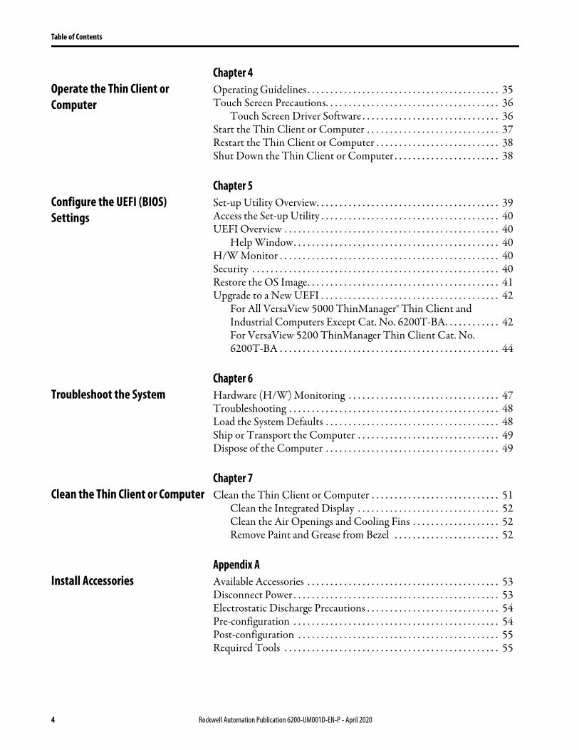
Table of Contents
Chapter 4Operate the Thin Client or Computer
Operating Guidelines . . . . . . . . . . . . . . . . . . . . . . . . . . . . . . . . . . . . . . . . . . 35Touch Screen Precautions. . . . . . . . . . . . . . . . . . . . . . . . . . . . . . . . . . . . . . 36
Touch Screen Driver Software . . . . . . . . . . . . . . . . . . . . . . . . . . . . . . 36Start the Thin Client or Computer . . . . . . . . . . . . . . . . . . . . . . . . . . . . . 37Restart the Thin Client or Computer . . . . . . . . . . . . . . . . . . . . . . . . . . . 38Shut Down the Thin Client or Computer . . . . . . . . . . . . . . . . . . . . . . . 38
Chapter 5Configure the UEFI (BIOS) Settings
Set-up Utility Overview. . . . . . . . . . . . . . . . . . . . . . . . . . . . . . . . . . . . . . . . 39Access the Set-up Utility . . . . . . . . . . . . . . . . . . . . . . . . . . . . . . . . . . . . . . . 40UEFI Overview . . . . . . . . . . . . . . . . . . . . . . . . . . . . . . . . . . . . . . . . . . . . . . . 40
Help Window. . . . . . . . . . . . . . . . . . . . . . . . . . . . . . . . . . . . . . . . . . . . . 40H/W Monitor . . . . . . . . . . . . . . . . . . . . . . . . . . . . . . . . . . . . . . . . . . . . . . . . 40Security . . . . . . . . . . . . . . . . . . . . . . . . . . . . . . . . . . . . . . . . . . . . . . . . . . . . . . 40Restore the OS Image. . . . . . . . . . . . . . . . . . . . . . . . . . . . . . . . . . . . . . . . . . 41Upgrade to a New UEFI . . . . . . . . . . . . . . . . . . . . . . . . . . . . . . . . . . . . . . . 42
For All VersaView 5000 ThinManager® Thin Client and Industrial Computers Except Cat. No. 6200T-BA. . . . . . . . . . . . 42For VersaView 5200 ThinManager Thin Client Cat. No. 6200T-BA . . . . . . . . . . . . . . . . . . . . . . . . . . . . . . . . . . . . . . . . . . . . . . . . 44
Chapter 6Troubleshoot the System Hardware (H/W) Monitoring . . . . . . . . . . . . . . . . . . . . . . . . . . . . . . . . . 47
Troubleshooting . . . . . . . . . . . . . . . . . . . . . . . . . . . . . . . . . . . . . . . . . . . . . . 48Load the System Defaults . . . . . . . . . . . . . . . . . . . . . . . . . . . . . . . . . . . . . . 48Ship or Transport the Computer . . . . . . . . . . . . . . . . . . . . . . . . . . . . . . . 49Dispose of the Computer . . . . . . . . . . . . . . . . . . . . . . . . . . . . . . . . . . . . . . 49
Chapter 7Clean the Thin Client or Computer Clean the Thin Client or Computer . . . . . . . . . . . . . . . . . . . . . . . . . . . . 51
Clean the Integrated Display . . . . . . . . . . . . . . . . . . . . . . . . . . . . . . . 52Clean the Air Openings and Cooling Fins . . . . . . . . . . . . . . . . . . . 52Remove Paint and Grease from Bezel . . . . . . . . . . . . . . . . . . . . . . . 52
Appendix AInstall Accessories Available Accessories . . . . . . . . . . . . . . . . . . . . . . . . . . . . . . . . . . . . . . . . . . 53
Disconnect Power . . . . . . . . . . . . . . . . . . . . . . . . . . . . . . . . . . . . . . . . . . . . . 53Electrostatic Discharge Precautions . . . . . . . . . . . . . . . . . . . . . . . . . . . . . 54Pre-configuration . . . . . . . . . . . . . . . . . . . . . . . . . . . . . . . . . . . . . . . . . . . . . 54Post-configuration . . . . . . . . . . . . . . . . . . . . . . . . . . . . . . . . . . . . . . . . . . . . 55Required Tools . . . . . . . . . . . . . . . . . . . . . . . . . . . . . . . . . . . . . . . . . . . . . . . 55
4 Rockwell Automation Publication 6200-UM001D-EN-P - April 2020
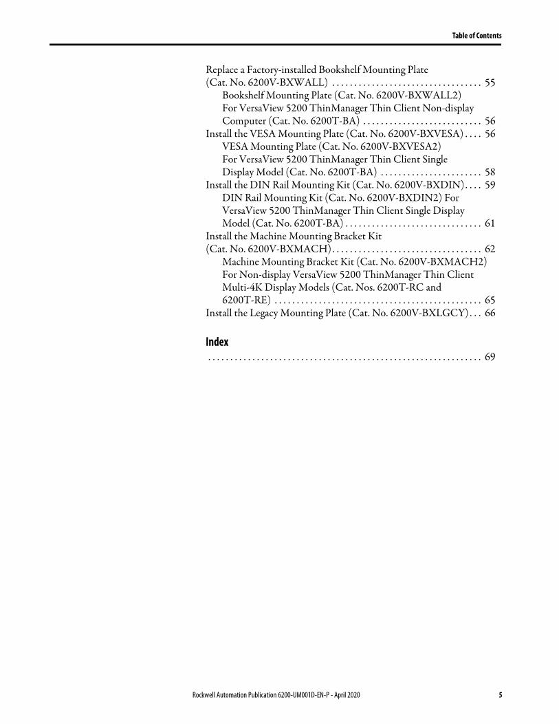
Table of Contents
Replace a Factory-installed Bookshelf Mounting Plate (Cat. No. 6200V-BXWALL) . . . . . . . . . . . . . . . . . . . . . . . . . . . . . . . . . . 55
Bookshelf Mounting Plate (Cat. No. 6200V-BXWALL2) For VersaView 5200 ThinManager Thin Client Non-display Computer (Cat. No. 6200T-BA) . . . . . . . . . . . . . . . . . . . . . . . . . . . 56
Install the VESA Mounting Plate (Cat. No. 6200V-BXVESA) . . . . 56VESA Mounting Plate (Cat. No. 6200V-BXVESA2) For VersaView 5200 ThinManager Thin Client Single Display Model (Cat. No. 6200T-BA) . . . . . . . . . . . . . . . . . . . . . . . 58
Install the DIN Rail Mounting Kit (Cat. No. 6200V-BXDIN). . . . 59DIN Rail Mounting Kit (Cat. No. 6200V-BXDIN2) For VersaView 5200 ThinManager Thin Client Single Display Model (Cat. No. 6200T-BA) . . . . . . . . . . . . . . . . . . . . . . . . . . . . . . . 61
Install the Machine Mounting Bracket Kit (Cat. No. 6200V-BXMACH). . . . . . . . . . . . . . . . . . . . . . . . . . . . . . . . . . 62
Machine Mounting Bracket Kit (Cat. No. 6200V-BXMACH2) For Non-display VersaView 5200 ThinManager Thin Client Multi-4K Display Models (Cat. Nos. 6200T-RC and 6200T-RE) . . . . . . . . . . . . . . . . . . . . . . . . . . . . . . . . . . . . . . . . . . . . . . . 65
Install the Legacy Mounting Plate (Cat. No. 6200V-BXLGCY). . . 66
Index . . . . . . . . . . . . . . . . . . . . . . . . . . . . . . . . . . . . . . . . . . . . . . . . . . . . . . . . . . . . . . 69
Rockwell Automation Publication 6200-UM001D-EN-P - April 2020 5

Table of Contents
Notes:
6 Rockwell Automation Publication 6200-UM001D-EN-P - April 2020
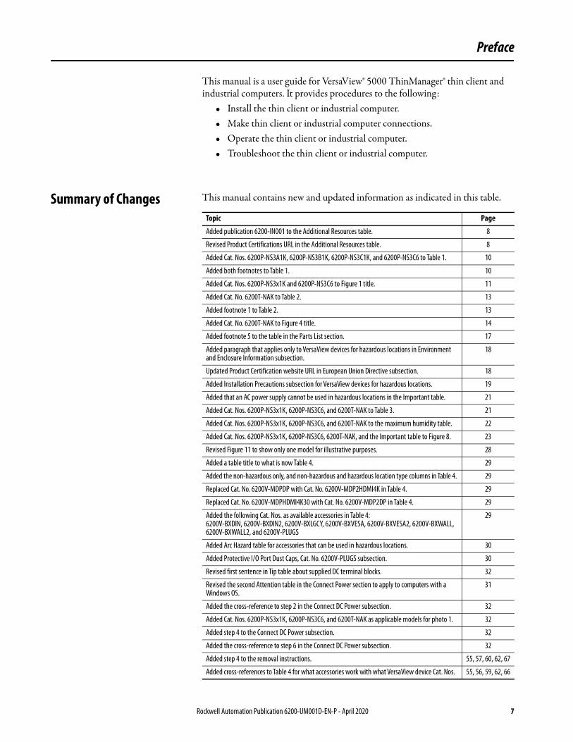
Preface
This manual is a user guide for VersaView® 5000 ThinManager® thin client and industrial computers. It provides procedures to the following:
• Install the thin client or industrial computer.• Make thin client or industrial computer connections.• Operate the thin client or industrial computer.• Troubleshoot the thin client or industrial computer.
Summary of Changes This manual contains new and updated information as indicated in this table.
Topic Page
Added publication 6200-IN001 to the Additional Resources table. 8
Revised Product Certifications URL in the Additional Resources table. 8
Added Cat. Nos. 6200P-NS3A1K, 6200P-NS3B1K, 6200P-NS3C1K, and 6200P-NS3C6 to Table 1. 10
Added both footnotes to Table 1. 10
Added Cat. Nos. 6200P-NS3x1K and 6200P-NS3C6 to Figure 1 title. 11
Added Cat. No. 6200T-NAK to Table 2. 13
Added footnote 1 to Table 2. 13
Added Cat. No. 6200T-NAK to Figure 4 title. 14
Added footnote 5 to the table in the Parts List section. 17
Added paragraph that applies only to VersaView devices for hazardous locations in Environment and Enclosure Information subsection.
18
Updated Product Certification website URL in European Union Directive subsection. 18
Added Installation Precautions subsection for VersaView devices for hazardous locations. 19
Added that an AC power supply cannot be used in hazardous locations in the Important table. 21
Added Cat. Nos. 6200P-NS3x1K, 6200P-NS3C6, and 6200T-NAK to Table 3. 21
Added Cat. Nos. 6200P-NS3x1K, 6200P-NS3C6, and 6200T-NAK to the maximum humidity table. 22
Added Cat. Nos. 6200P-NS3x1K, 6200P-NS3C6, 6200T-NAK, and the Important table to Figure 8. 23
Revised Figure 11 to show only one model for illustrative purposes. 28
Added a table title to what is now Table 4. 29
Added the non-hazardous only, and non-hazardous and hazardous location type columns in Table 4. 29
Replaced Cat. No. 6200V-MDPDP with Cat. No. 6200V-MDP2HDMI4K in Table 4. 29
Replaced Cat. No. 6200V-MDPHDMI4K30 with Cat. No. 6200V-MDP2DP in Table 4. 29
Added the following Cat. Nos. as available accessories in Table 4:6200V-BXDIN, 6200V-BXDIN2, 6200V-BXLGCY, 6200V-BXVESA, 6200V-BXVESA2, 6200V-BXWALL, 6200V-BXWALL2, and 6200V-PLUGS
29
Added Arc Hazard table for accessories that can be used in hazardous locations. 30
Added Protective I/O Port Dust Caps, Cat. No. 6200V-PLUGS subsection. 30
Revised first sentence in Tip table about supplied DC terminal blocks. 32
Revised the second Attention table in the Connect Power section to apply to computers with a Windows OS.
31
Added the cross-reference to step 2 in the Connect DC Power subsection. 32
Added Cat. Nos. 6200P-NS3x1K, 6200P-NS3C6, and 6200T-NAK as applicable models for photo 1. 32
Added step 4 to the Connect DC Power subsection. 32
Added the cross-reference to step 6 in the Connect DC Power subsection. 32
Added step 4 to the removal instructions. 55, 57, 60, 62, 67
Added cross-references to Table 4 for what accessories work with what VersaView device Cat. Nos. 55, 56, 59, 62, 66
Rockwell Automation Publication 6200-UM001D-EN-P - April 2020 7
Preface
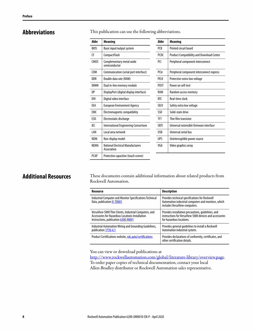
Abbreviations This publication can use the following abbreviations.
Additional Resources These documents contain additional information about related products from Rockwell Automation.
You can view or download publications athttp://www.rockwellautomation.com/global/literature-library/overview.page. To order paper copies of technical documentation, contact your local Allen-Bradley distributor or Rockwell Automation sales representative.
Abbr Meaning Abbr Meaning
BIOS Basic input/output system PCB Printed circuit board
CF CompactFlash PCDC Product Compatibility and Download Center
CMOS Complementary metal oxide semiconductor
PCI Peripheral component interconnect
COM Communication (serial port interface) PCIe Peripheral component interconnect express
DDR Double data rate (RAM) PELV Protective extra-low voltage
DIMM Dual in-line memory module POST Power on self-test
DP DisplayPort (digital display interface) RAM Random access memory
DVI Digital video interface RTC Real-time clock
EEA European Environment Agency SELV Safety extra low voltage
EMC Electromagnetic compatibility SSD Solid-state drive
ESD Electrostatic discharge TFT Thin film transistor
IEC International Engineering Consortium UEFI Universal extensible firmware interface
LAN Local area network USB Universal serial bus
NDM Non-display model UPS Uninterruptible power source
NEMA National Electrical Manufacturers Association
VGA Video graphics array
PCAP Protective capacitive (touch screen)
Resource Description
Industrial Computer and Monitor Specifications Technical Data, publication IC-TD001
Provides technical specifications for Rockwell Automation industrial computers and monitors, which includes VersaView computers.
VersaView 5000 Thin Clients, Industrial Computers, and Accessories for Hazardous Locations Installation Instructions, publication 6200-IN001
Provides installation precautions, guidelines, and instructions for VersaView 5000 devices and accessories for hazardous locations.
Industrial Automation Wiring and Grounding Guidelines, publication 1770-4.1
Provides general guidelines to install a Rockwell Automation industrial system.
Product Certifications website, rok.auto/certifications Provides declarations of conformity, certificates, and other certification details.
8 Rockwell Automation Publication 6200-UM001D-EN-P - April 2020
Chapter 1
VersaView 5400 Industrial Computer Features
The Allen-Bradley® VersaView® 5400 portfolio is a line of industrial computers that can be used for standalone machine-level and distributed HMI applications. The open architecture supports modern operating systems and various software applications, including FactoryTalk® software for distributed applications.
The VersaView 5400 integrated display computers have an edge-to-edge, all glass, ten-point multi-touch screen that can also be operated with gloves. The touch screens are precalibrated so that recalibration is not necessary.
The line is fanless with little maintenance needed, which helps reduce costly machine downtime.
All VersaView non-display computers perform the same as the integrated display computers, in a compact design that supports multiple mounting options.
Operating Systems The following Microsoft®-licensed operating systems are available:• Windows® 7 Professional (64 bit), SP 1• Windows Embedded Standard (WES) 7 (64 bit)• Windows 10 Internet of Things (IoT) Enterprise (64 bit)
No operating system updates have been applied to the factory image beyond the listed service packs.
To obtain a copy of a factory system image, contact your local technical support center or access the Rockwell Automation® PCDC site:https://compatibility.rockwellautomation.com/Pages/home.aspx.
Topic Page
Operating Systems 9
Computer Options 10
Hardware Features 11
Rockwell Automation Publication 6200-UM001D-EN-P - April 2020 9
Chapter 1 VersaView 5400 Industrial Computer Features
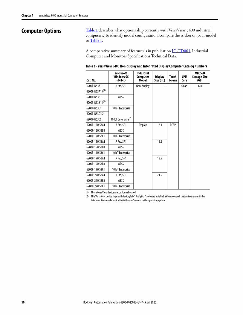
Computer Options Table 1 describes what options ship currently with VersaView 5400 industrial computers. To identify model configuration, compare the sticker on your model to Table 1.
A comparative summary of features is in publication IC-TD001, Industrial Computer and Monitors Specifications Technical Data.
Table 1 - VersaView 5400 Non-display and Integrated Display Computer Catalog Numbers
Cat. No.
Microsoft Windows OS
(64 bit)
Industrial Computer
ModelDisplay
Size (in.)Touch Screen
CPU Core
MLC SSDStorage Size
(GB)
6200P-NS3A1 7 Pro, SP1 Non-display — Quad 128
6200P-NS3A1K(1)
(1) These VersaView devices are conformal coated.
6200P-NS3B1 WES 7
6200P-NS3B1K(1)
6200P-NS3C1 10 IoT Enterprise
6200P-NS3C1K(1)
6200P-NS3C6 10 IoT Enterprise(2)
(2) This VersaView device ships with FactoryTalk® Analytics™ software installed. When accessed, that software runs in the Windows Kiosk mode, which limits the user’s access to the operating system.
6200P-12WS3A1 7 Pro, SP1 Display 12.1 PCAP
6200P-12WS3B1 WES 7
6200P-12WS3C1 10 IoT Enterprise
6200P-15WS3A1 7 Pro, SP1 15.6
6200P-15WS3B1 WES 7
6200P-15WS3C1 10 IoT Enterprise
6200P-19WS3A1 7 Pro, SP1 18.5
6200P-19WS3B1 WES 7
6200P-19WS3C1 10 IoT Enterprise
6200P-22WS3A1 7 Pro, SP1 21.5
6200P-22WS3B1 WES 7
6200P-22WS3C1 10 IoT Enterprise
10 Rockwell Automation Publication 6200-UM001D-EN-P - April 2020
VersaView 5400 Industrial Computer Features Chapter 1
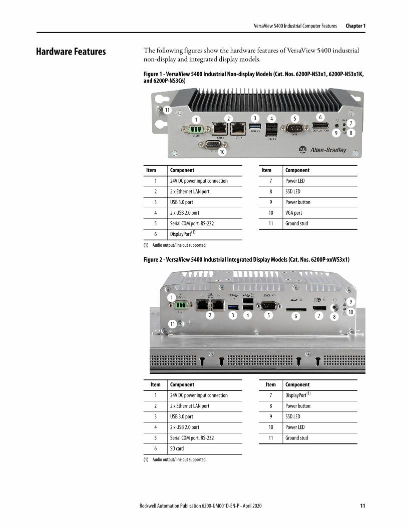
Hardware Features The following figures show the hardware features of VersaView 5400 industrial non-display and integrated display models.
Figure 1 - VersaView 5400 Industrial Non-display Models (Cat. Nos. 6200P-NS3x1, 6200P-NS3x1K, and 6200P-NS3C6)
Figure 2 - VersaView 5400 Industrial Integrated Display Models (Cat. Nos. 6200P-xxWS3x1)
Item Component Item Component
1 24V DC power input connection 7 Power LED
2 2 x Ethernet LAN port 8 SSD LED
3 USB 3.0 port 9 Power button
4 2 x USB 2.0 port 10 VGA port
5 Serial COM port, RS-232 11 Ground stud
6 DisplayPort(1)
(1) Audio output/line out supported.
Item Component Item Component
1 24V DC power input connection 7 DisplayPort(1)
(1) Audio output/line out supported.
2 2 x Ethernet LAN port 8 Power button
3 USB 3.0 port 9 SSD LED
4 2 x USB 2.0 port 10 Power LED
5 Serial COM port, RS-232 11 Ground stud
6 SD card
1 2 3 4 5 6
10
9
7
8
11
1
2 3 4 5 6 7 8
9
10
11
Rockwell Automation Publication 6200-UM001D-EN-P - April 2020 11

Chapter 1 VersaView 5400 Industrial Computer Features
Notes:
12 Rockwell Automation Publication 6200-UM001D-EN-P - April 2020
Chapter 2
VersaView 5200 ThinManager Thin Client Features
The Allen-Bradley® VersaView® 5200 ThinManager® thin clients work exclusively with ThinManager software for centrally-managed content delivery. Integrated display and non-display versions are available.
Thin Client Options Table 2 describes what options ship currently with VersaView 5200 thin clients. To identify your model’s configuration, compare the sticker on your model to Table 2.
A comparative summary of features is in publication IC-TD001, Industrial Computer and Monitors Specifications Technical Data.
Table 2 - VersaView 5200 ThinManager Thin Client Non-display and Display Catalog Numbers
Topic Page
Thin Client Options 13
Hardware Features 14
Cat. No.Windows
OSThin Client
ModelDisplay
Size (in.)Touch Screen
CPU Core
MLC SSDStorage Size
(GB)
No. of External Displays
6200T-BA — Non-display — Single — 1
6200T-NA 2
6200T-NAK(1)
(1) This VersaView device is conformal coated.
6200T-KB Quad 2(2)
(2) These external display ports support 4K resolution.
6200T-RC 3(2)
6200T-RE 7(2)
6200T-12WA Display 12.1 PCAP Single 1
6200T-15WA 15.6
6200T-19WA 18.5
6200T-22WA 21.5
Rockwell Automation Publication 6200-UM001D-EN-P - April 2020 13
Chapter 2 VersaView 5200 ThinManager Thin Client Features
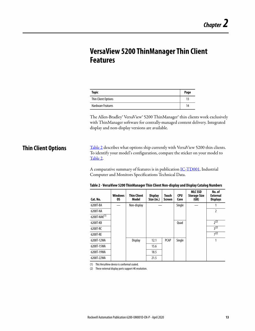
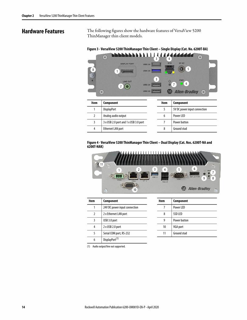
Hardware Features The following figures show the hardware features of VersaView 5200 ThinManager thin client models.
Figure 3 - VersaView 5200 ThinManager Thin Client – Single Display (Cat. No. 6200T-BA)
Figure 4 - VersaView 5200 ThinManager Thin Client – Dual Display (Cat. Nos. 6200T-NA and 6200T-NAK)
Item Component Item Component
1 DisplayPort 5 5V DC power input connection
2 Analog audio output 6 Power LED
3 3 x USB 2.0 port and 1 x USB 3.0 port 7 Power button
4 Ethernet LAN port 8 Ground stud
Item Component Item Component
1 24V DC power input connection 7 Power LED
2 2 x Ethernet LAN port 8 SSD LED
3 USB 3.0 port 9 Power button
4 2 x USB 2.0 port 10 VGA port
5 Serial COM port, RS-232 11 Ground stud
6 DisplayPort(1)
(1) Audio output/line out supported.
1
2
3 4
5
673
8
1 2 3 4 5 6
10
9
7
8
11
14 Rockwell Automation Publication 6200-UM001D-EN-P - April 2020
VersaView 5200 ThinManager Thin Client Features Chapter 2
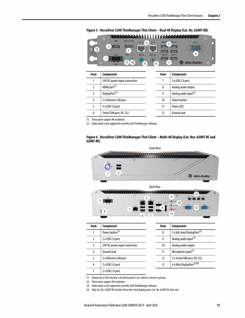
Figure 5 - VersaView 5200 ThinManager Thin Client – Dual 4K Display (Cat. No. 6200T-KB)
Figure 6 - VersaView 5200 ThinManager Thin Client – Multi-4K Display (Cat. Nos. 6200T-RC and 6200T-RE)
Item Component Item Component
1 24V DC power input connection 7 2 x USB 2.0 port
2 HDMI port(1)
(1) These ports support 4K resolution.
8 Analog audio output
3 DisplayPort(1) 9 Analog audio input(2)
(2) Audio input is not supported currently with ThinManager software.
4 2 x Ethernet LAN port 10 Power button
5 4 x USB 3.0 port 11 Power LED
6 Serial COM port, RS-232 12 Ground stud
Item Component Item Component
1 Power button(1)
(1) Button has a LED ring that is lit when power is on, which is shown in picture.
8 3 x full-sized DisplayPort(2)
(2) These ports support 4K resolution.
2 2 x USB 2.0 port 9 Analog audio input(3)
(3) Audio input is not supported currently with ThinManager software.
3 24V DC power input connection 10 Analog audio output
4 Ground stud 11 Microphone input(3)
5 3 x Ethernet LAN port 12 2 x Serial COM port, RS-232
6 2 x USB 3.0 port 13 4 x Mini DisplayPort(2)(4)
(4) Only Cat. No. 6200T-RE includes these four mini display ports; Cat. No. 6200T-RC does not.
7 2 x USB 2.0 port
1
23
4 5
6
11 9 7810
12
1
13
3
4
5
6 11
9
7
810
2
125
Front View
Back View
Rockwell Automation Publication 6200-UM001D-EN-P - April 2020 15
Chapter 2 VersaView 5200 ThinManager Thin Client Features
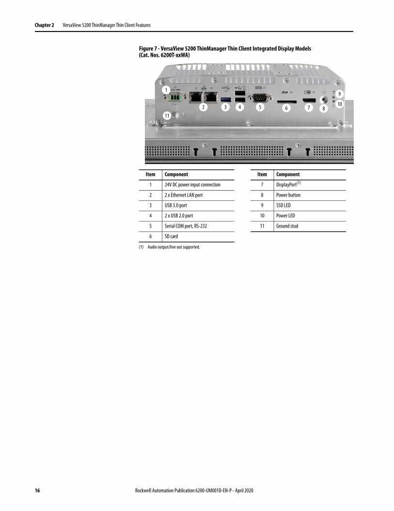
Figure 7 - VersaView 5200 ThinManager Thin Client Integrated Display Models (Cat. Nos. 6200T-xxWA)
Item Component Item Component
1 24V DC power input connection 7 DisplayPort(1)
(1) Audio output/line out supported.
2 2 x Ethernet LAN port 8 Power button
3 USB 3.0 port 9 SSD LED
4 2 x USB 2.0 port 10 Power LED
5 Serial COM port, RS-232 11 Ground stud
6 SD card
1
2 3 4 5 6 7 8
9
10
11
16 Rockwell Automation Publication 6200-UM001D-EN-P - April 2020
Chapter 3
Install the Thin Client or Computer
Before You Begin Before you unpack your VersaView® 5000 ThinManager® thin client or industrial computer, inspect the shipping carton for damage. If damage is visible, immediately contact the shipper and request assistance. Otherwise, proceed with unpacking.
Keep the original packing material in case you need to return the VersaView thin client or computer for repair or transport it to another location. Use both the inner and outer packing cartons to provide adequate protection for equipment returned for service.
Parts List VersaView thin clients or computers ship with the following items.
Topic Page
Before You Begin 17
Parts List 17
Installation Precautions 18
Hazardous Location Categories 19
Mounting Clearance Requirements 22
Dimensions 23
Required Tools 25
Install the Thin Client or Computer 25
Connect Peripherals 29
Connect Power 31
Item Description
Hardware • Mounting clips(1)
• DC terminal block(2)
• AC-to-DC power adapter, Cat. No. 6200V-MPS5(3)
• Four rubber mount pads(4)(5)
(1) Shipped only with VersaView thin client and industrial computers with integrated display models.(2) DC terminal block does not ship with the Cat. No. 6200T-BA ThinManager thin client model.(3) Shipped only with the Cat. No. 6200T-BA ThinManager thin client model.(4) Shipped only with non-display industrial computers and non-display ThinManager thin client models.(5) Although supplied, the four pads cannot be used as a mounting method for VersaView devices meant for hazardous locations.
Documents • VersaView 5100 Industrial Monitors, VersaView 5000 Thin Clients, Industrial Computers, and Accessories Product Information, publication 6200-PC001
• VersaView 5000 Thin Clients, Industrial Computers, and Accessories for Hazardous Locations Installation Instructions, publication 6200-IN001(6)
• VersaView 5000 Thin Client and Integrated Display Industrial Computers Cutout Template, publication 6200-DS001(1)
(6) This publication ships only with VersaView 5000 thin client and industrial computers for hazardous locations.
Rockwell Automation Publication 6200-UM001D-EN-P - April 2020 17
Chapter 3 Install the Thin Client or Computer
Installation Precautions Read and follow these precautions before you install your VersaView thin client or industrial computer.
Environment and Enclosure Information
European Union Directive
VersaView 5000 ThinManager thin client and industrial computers meet the European Union Directive requirements when installed within the European Union or EEA regions and have the CE marking. A copy of the declaration of the conformity is available at Product Certifications website.
ATTENTION: This equipment is intended for use in a Pollution Degree 2 industrial environment, in overvoltage Category II applications (as defined in IEC 60664-1), at altitudes up to 2000 m (6561 ft) without derating.This equipment is UL Listed, and considered Group 1, Class A industrial equipment according to IEC/CISPR 32. Without appropriate precautions, there can be potential difficulties with electromagnetic compatibility in other environments due to conducted and radiated disturbance.All VersaView integrated display thin clients and industrial computers are shipped with a gasketed bezel to meet specified NEMA, UL Type, and IEC IP ratings only when mounted in a panel or enclosure with an equivalent rating.This paragraph applies only to VersaView devices for hazardous locations: This equipment is supplied as an open type equipment. To meet some regulatory requirements, the equipment must be mounted in an enclosure that is suitably designed for environmental conditions that can be present and appropriately designed to help prevent personal injury resulting from accessibility to live parts. The interior of the enclosure must be accessible only by using a tool. In addition to this publication, see the following:• Industrial Automation Wiring and Grounding Guidelines, publication
1770-4.1, for more installation requirements• NEMA 250 and IEC 60529, as applicable, for explanations of the degrees of
protection provided by enclosures
ATTENTION: This equipment is intended to operate in an industrial or control room environment, which uses some form of power isolation from the public low-voltage mains. To comply with EN 55024 and EN 55032, all cables, except for Ethernet cables, must be used indoors. These cables cannot exit the building at any point and cannot directly connect to cables outside the building. All I/O cables, except for Ethernet cables and serial port (COM) cables, must be less than 3 m (9.842 ft).
18 Rockwell Automation Publication 6200-UM001D-EN-P - April 2020
Install the Thin Client or Computer Chapter 3
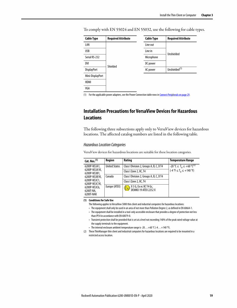
To comply with EN 55024 and EN 55032, use the following for cable types.
Installation Precautions for VersaView Devices for Hazardous Locations
The following three subsections apply only to VersaView devices for hazardous locations. The affected catalog numbers are listed in the following table.
Hazardous Location Categories
VersaView devices for hazardous locations are suitable for these location categories.
Cable Type Required Attribute Cable Type Required Attribute
LAN
Shielded
Line out
UnshieldedUSB Line in
Serial RS-232 Microphone
DVI DC power
DisplayPort AC power Unshielded(1)
(1) For the applicable power adapters, see the Power Connection table rows in Connect Peripherals on page 29.
Mini-DisplayPort
HDMI
VGA
Cat. Nos.(1)
(1) Conditions for Safe UseThe following applies to VersaView 5000 thin client and industrial computers for hazardous locations:• The equipment shall only be used in an area of not more than Pollution Degree 2, as defined in EN 60664-1.• The equipment shall be installed in a tool-only accessible enclosure that provides a degree of protection not less
than IP54 in accordance with EN 60079-0.• Transient protection shall be provided that is set at a level not exceeding 140% of the peak rated voltage value at
the supply terminals to the equipment.• The internal enclosure ambient temperature range is -20…+60 °C (-4…+140 °F).
Region Rating Temperature Range
6200P-NS3A1,6200P-NS3A1K,6200P-NS3B1,6200P-NS3B1K,6200P-NS3C1,6200P-NS3C1K,6200P-NS3C6,6200T-NA,6200T-NAK
United States Class I Division 2, Groups A, B, C, D T4 -20 °C ≤ Ta ≤ +60 °C(2)
(-4 °F ≤ Ta ≤ +140 °F)
(2) These ThinManager thin client and industrial computers for hazardous locations are required to be mounted in a restricted access location.
Class I Zone 2, IIC, T4Canada Class I Division 2, Groups A, B, C, D T4
Class I Zone 2, IIC, T4Europe (ATEX) II 3 G, Ex ec IIC T4 Gc,
DEMKO 19 ATEX 2252 X
Rockwell Automation Publication 6200-UM001D-EN-P - April 2020 19
Chapter 3 Install the Thin Client or Computer
The following statement applies to when the VersaView device for hazardous locations is used in a hazardous location.
Restricted Access Location
Verify that restricted access locations meet these conditions for the VersaView 5000 devices for hazardous locations:
• Access is gained only by service personnel or by users who have been instructed on the reasons for restrictions to a location and about any precautions to be taken.
• Access is by using a tool, a lock and key, or other means of security controlled by the authority responsible for the location.
WARNING: Explosion Hazard• Substitution of components can impair suitability for hazardous locations.• Do not disconnect equipment unless power has been switched off and the area
is known to be non-hazardous.• Do not connect or disconnect components unless power has been switched off.• Use only peripheral equipment that is suitable for hazardous locations. For a
list of suitable peripheral equipment, see the table in Connect Peripherals on page 29.
• In the U.S., all wiring must be in accordance with Class I, Division 2 wiring methods of Article 501 of the National Electrical Code, and in accordance with the authority having jurisdiction. For power wiring requirements, see the table in Installation Guidelines on page 21.
• In Canada, all wiring must be in accordance with Section 18-1J2 of the Canadian Electrical Code, and in accordance with the authority having jurisdiction. For power wiring requirements, see the table in Installation Guidelines on page 21.
• In final applications, properly connect these devices to ground by using the ground terminal screw on the device chassis, the ground screw on the factory installed mounting bracket, or the ground terminal on the terminal block.
ATTENTION: VersaView 5000 devices for hazardous locations must be installed in a restricted access location.
20 Rockwell Automation Publication 6200-UM001D-EN-P - April 2020

Install the Thin Client or Computer Chapter 3
Installation Guidelines Follow these guidelines to make sure your VersaView thin client or industrial computer provides service with excellent reliability:
• The installation site must have sufficient power.
• Verify that the DC power wires meet these requirements:
• In dry environments, static charges can build up easily. Proper grounding of the thin client or computer helps to reduce static discharges, which can cause shock and damage electronic components.
• The ambient air temperature must not exceed the maximum operating temperature in Table 3.
Table 3 - Maximum Operating Temperature Ranges
ATTENTION: For applications with an AC power source, the shipped or optional AC-to-DC power adapter must be plugged into a grounded outlet to maintain an electrically safe installation.An AC power supply cannot be used in a hazardous location.
Attribute Requirement
Wire material Stranded copper
Wire gauge• To connect to DC terminal block• To connect to earth ground
• 0.326…3.31 mm2 (22…12 AWG)• 1.5 mm2 (16 AWG) or larger
Wire temperature rating, min 72° C (162° F)
Torque values• To connect wires to DC terminal block• To connect to earth ground(1)
(1) On either computer chassis or factory-installed bookshelf mounting bracket.
• 0.22…0.25 N•m (1.95…2.21 lb•in)• 3.1 N•m (2.29 lb•in)
VersaView Model Cat. Nos. Temperature, max
5200 ThinManager thin client
Non-display 6200T-BA 0…50 °C (32…122 °F)
6200T-KB 0…55 °C (32…131 °F)
6200T-RC, 6200T-RE 0…45 °C (32…113 °F
6200T-NA, 6200T-NAK -20…+60 °C (-4…+140 °F)
Display 6200T-xxWA 0…50 °C (32…122 °F)
5400 Industrial Computers Non-display 6200P-NSxA1,6200P-NSxA1K,6200P-NS3C6
-20…+60 °C (-4…+140 °F)
Display 6200P-xxWS3x1 0…50 °C (32…122 °F)
IMPORTANT VersaView thin clients and industrial computers can operate at a range of extremes. However, the life span of any electronic device is shortened if you continuously operate it at its highest rated temperature, which includes the touch screen and LCD panel.
Rockwell Automation Publication 6200-UM001D-EN-P - April 2020 21
Chapter 3 Install the Thin Client or Computer
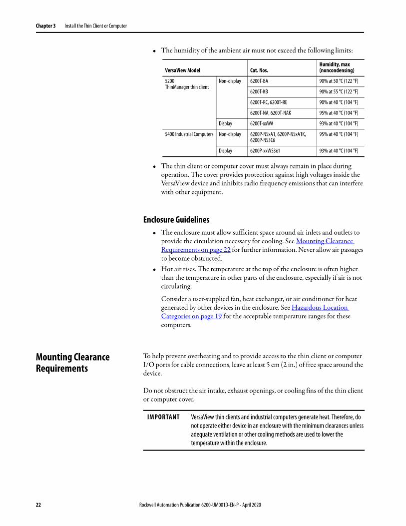
• The humidity of the ambient air must not exceed the following limits:
• The thin client or computer cover must always remain in place during operation. The cover provides protection against high voltages inside the VersaView device and inhibits radio frequency emissions that can interfere with other equipment.
Enclosure Guidelines• The enclosure must allow sufficient space around air inlets and outlets to
provide the circulation necessary for cooling. See Mounting Clearance Requirements on page 22 for further information. Never allow air passages to become obstructed.
• Hot air rises. The temperature at the top of the enclosure is often higher than the temperature in other parts of the enclosure, especially if air is not circulating.
Consider a user-supplied fan, heat exchanger, or air conditioner for heat generated by other devices in the enclosure. See Hazardous Location Categories on page 19 for the acceptable temperature ranges for these computers.
Mounting Clearance Requirements
To help prevent overheating and to provide access to the thin client or computer I/O ports for cable connections, leave at least 5 cm (2 in.) of free space around the device.
Do not obstruct the air intake, exhaust openings, or cooling fins of the thin client or computer cover.
VersaView Model Cat. Nos.Humidity, max (noncondensing)
5200 ThinManager thin client
Non-display 6200T-BA 90% at 50 °C (122 °F)
6200T-KB 90% at 55 °C (122 °F)
6200T-RC, 6200T-RE 90% at 40 °C (104 °F)
6200T-NA, 6200T-NAK 95% at 40 °C (104 °F)
Display 6200T-xxWA 93% at 40 °C (104 °F)
5400 Industrial Computers Non-display 6200P-NSxA1, 6200P-NSxA1K,6200P-NS3C6
95% at 40 °C (104 °F)
Display 6200P-xxWS3x1 93% at 40 °C (104 °F)
IMPORTANT VersaView thin clients and industrial computers generate heat. Therefore, do not operate either device in an enclosure with the minimum clearances unless adequate ventilation or other cooling methods are used to lower the temperature within the enclosure.
22 Rockwell Automation Publication 6200-UM001D-EN-P - April 2020
Install the Thin Client or Computer Chapter 3
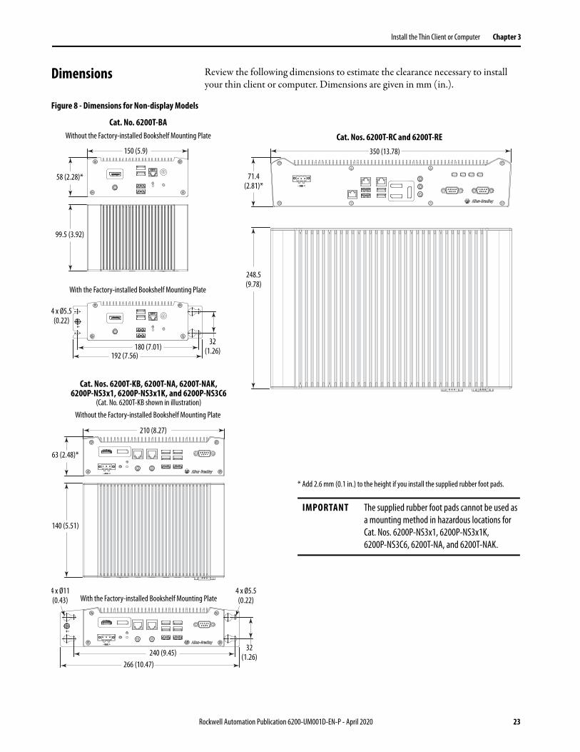
Dimensions Review the following dimensions to estimate the clearance necessary to install your thin client or computer. Dimensions are given in mm (in.).
Figure 8 - Dimensions for Non-display Models
210 (8.27)
140 (5.51)
63 (2.48)*
Without the Factory-installed Bookshelf Mounting Plate
With the Factory-installed Bookshelf Mounting Plate
Cat. No. 6200T-BA
Cat. Nos. 6200T-KB, 6200T-NA, 6200T-NAK,6200P-NS3x1, 6200P-NS3x1K, and 6200P-NS3C6
(Cat. No. 6200T-KB shown in illustration)
Without the Factory-installed Bookshelf Mounting Plate
With the Factory-installed Bookshelf Mounting Plate
150 (5.9)
58 (2.28)*
240 (9.45)
99.5 (3.92)
4 x Ø11 (0.43)
32 (1.26)
4 x Ø5.5 (0.22)
266 (10.47)
4 x Ø5.5 (0.22)
180 (7.01)192 (7.56)
32 (1.26)
* Add 2.6 mm (0.1 in.) to the height if you install the supplied rubber foot pads.
IMPORTANT The supplied rubber foot pads cannot be used as a mounting method in hazardous locations for Cat. Nos. 6200P-NS3x1, 6200P-NS3x1K, 6200P-NS3C6, 6200T-NA, and 6200T-NAK.
Cat. Nos. 6200T-RC and 6200T-RE350 (13.78)
248.5 (9.78)
71.4 (2.81)*
Rockwell Automation Publication 6200-UM001D-EN-P - April 2020 23
Chapter 3 Install the Thin Client or Computer
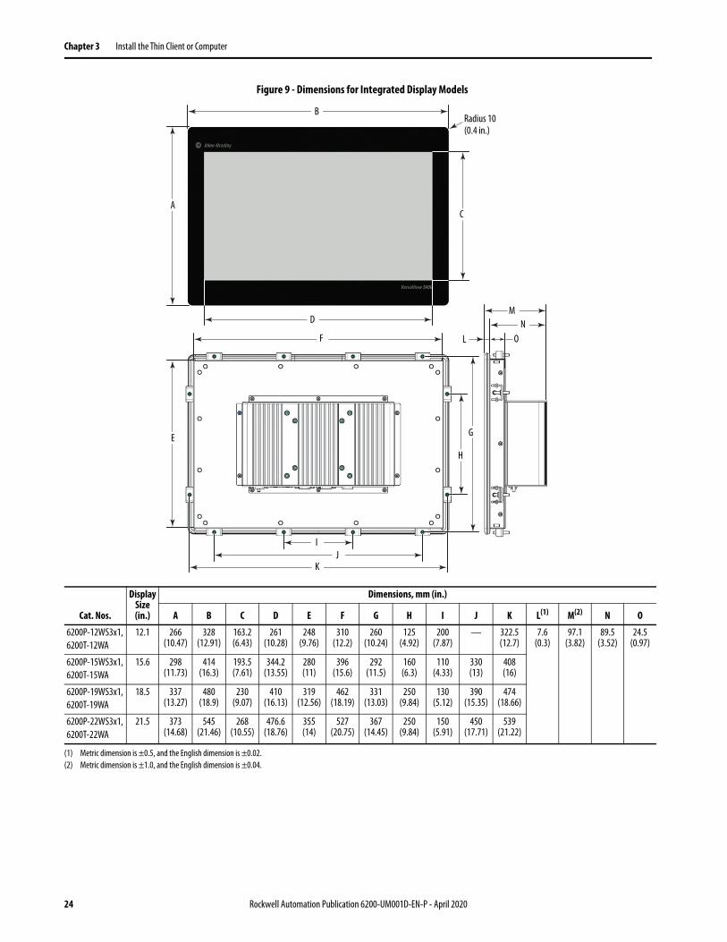
Figure 9 - Dimensions for Integrated Display Models
B
AC
D
E
F
G
H
IJ
K
MN
L O
Radius 10 (0.4 in.)
Cat. Nos.
Display Size (in.)
Dimensions, mm (in.)
A B C D E F G H I J K L(1) M(2) N O
6200P-12WS3x1,6200T-12WA
12.1 266(10.47)
328(12.91)
163.2(6.43)
261(10.28)
248(9.76)
310(12.2)
260(10.24)
125(4.92)
200(7.87)
— 322.5(12.7)
7.6(0.3)
97.1(3.82)
89.5(3.52)
24.5(0.97)
6200P-15WS3x1,6200T-15WA
15.6 298(11.73)
414(16.3)
193.5(7.61)
344.2(13.55)
280(11)
396(15.6)
292(11.5)
160(6.3)
110(4.33)
330(13)
408(16)
6200P-19WS3x1,6200T-19WA
18.5 337(13.27)
480(18.9)
230(9.07)
410(16.13)
319(12.56)
462(18.19)
331(13.03)
250(9.84)
130(5.12)
390(15.35)
474(18.66)
6200P-22WS3x1,6200T-22WA
21.5 373(14.68)
545(21.46)
268(10.55)
476.6(18.76)
355(14)
527(20.75)
367(14.45)
250(9.84)
150(5.91)
450(17.71)
539(21.22)
(1) Metric dimension is ±0.5, and the English dimension is ±0.02.(2) Metric dimension is ±1.0, and the English dimension is ±0.04.
24 Rockwell Automation Publication 6200-UM001D-EN-P - April 2020
Install the Thin Client or Computer Chapter 3
Required Tools These tools are required to install all VersaView 5000 models:• #2 cross-head screwdriver• Panel cutout tools (for wall and panel mounting)• 2 mm Allen wrench (for mounting clips on integrated display models)• Drill motor and drill bit (for wall, machine, and table mounting)• T10 Torx key or screwdriver (to install optional brackets)• Anti-static wriststrap
Install the Thin Client or Computer
The computers support the following mounting options:• Panel mount (for integrated display models)• Wall mount (for non-display models)
Panel Mounting Guidelines
Observe these guidelines when you install an integrated display thin client or computer in a panel.
• Remove all electrical power from the panel before you make the cutout.• Confirm that there is adequate space behind the panel. For specific
information, refer to Mounting Clearance Requirements on page 22.• Cut supporting panels to specifications before installation. Take
precautions so metal cuttings do not enter components already installed in panel.
The supplied mounting hardware accommodates panel thickness between 1.5…6 mm (0.06…0.24 in.).
• Make sure the area around the panel cutout is clear.• The only acceptable mounting position is in the horizontal position with
the I/O ports at the bottom.• For VESA mounting of non-display thin clients or computers, the
installation must provide sufficient mechanical stability to minimize the effects from vibration and shock. The mounting means must be firmly attached to the supporting surface with the appropriate hardware.
TIP All non-display models ship with a factory-installed mounting plate for wall mounting, except for Cat. Nos. 6200T-RC and 6200T-RE.Instructions for other available mounting plates and mounting options are detailed in Appendix A, Install Accessories, starting on page 53.
ATTENTION: Failure to follow these guidelines can result in personal injury or damage to the panel components.
IMPORTANT VESA mounting reduces the computer IP rating from IP65 to IP20.
Rockwell Automation Publication 6200-UM001D-EN-P - April 2020 25
Chapter 3 Install the Thin Client or Computer
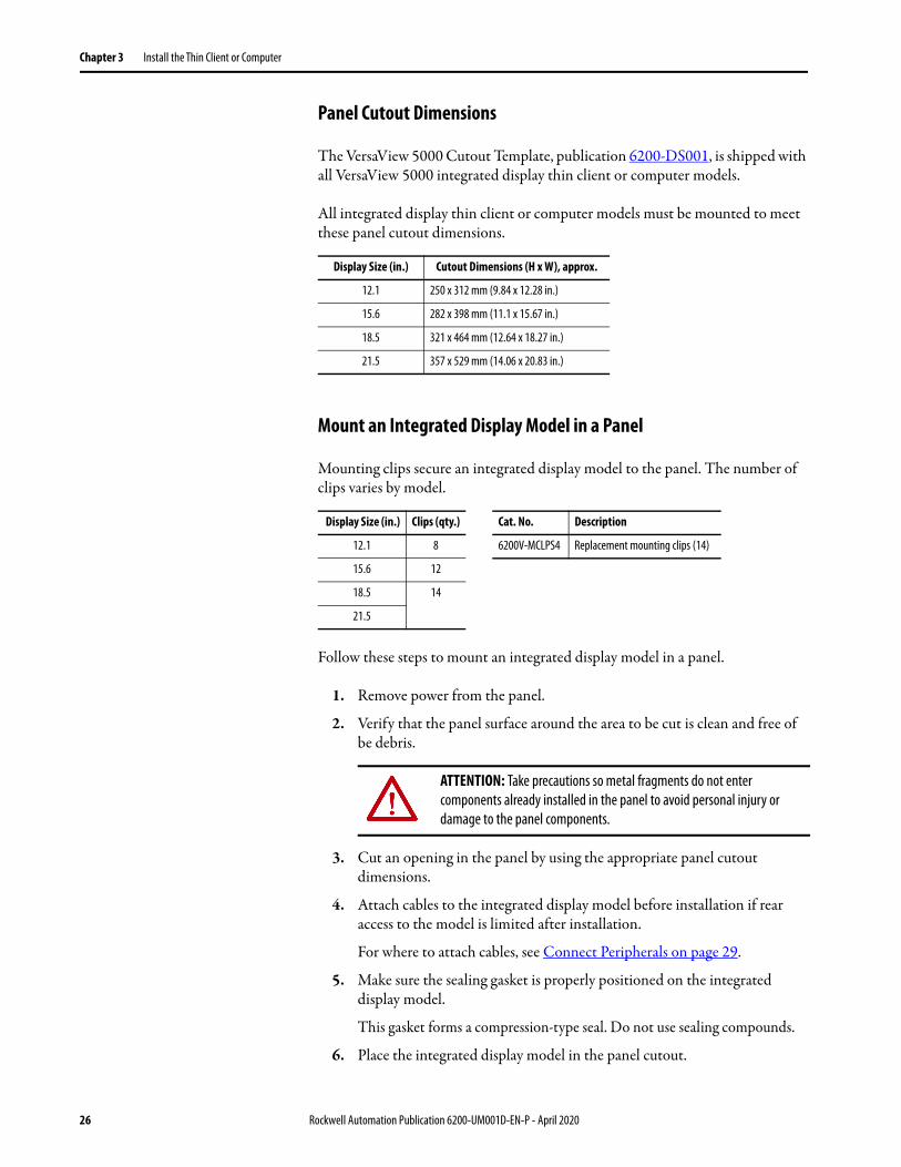
Panel Cutout Dimensions
The VersaView 5000 Cutout Template, publication 6200-DS001, is shipped with all VersaView 5000 integrated display thin client or computer models.
All integrated display thin client or computer models must be mounted to meet these panel cutout dimensions.
Mount an Integrated Display Model in a Panel
Mounting clips secure an integrated display model to the panel. The number of clips varies by model.
Follow these steps to mount an integrated display model in a panel.
1. Remove power from the panel.
2. Verify that the panel surface around the area to be cut is clean and free of be debris.
3. Cut an opening in the panel by using the appropriate panel cutout dimensions.
4. Attach cables to the integrated display model before installation if rear access to the model is limited after installation.
For where to attach cables, see Connect Peripherals on page 29.
5. Make sure the sealing gasket is properly positioned on the integrated display model.
This gasket forms a compression-type seal. Do not use sealing compounds.
6. Place the integrated display model in the panel cutout.
Display Size (in.) Cutout Dimensions (H x W), approx.
12.1 250 x 312 mm (9.84 x 12.28 in.)
15.6 282 x 398 mm (11.1 x 15.67 in.)
18.5 321 x 464 mm (12.64 x 18.27 in.)
21.5 357 x 529 mm (14.06 x 20.83 in.)
Display Size (in.) Clips (qty.) Cat. No. Description
12.1 8 6200V-MCLPS4 Replacement mounting clips (14)
15.6 12
18.5 14
21.5
ATTENTION: Take precautions so metal fragments do not enter components already installed in the panel to avoid personal injury or damage to the panel components.
26 Rockwell Automation Publication 6200-UM001D-EN-P - April 2020
Install the Thin Client or Computer Chapter 3
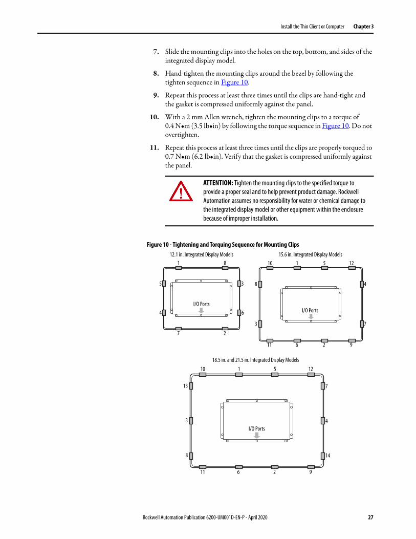
7. Slide the mounting clips into the holes on the top, bottom, and sides of the integrated display model.
8. Hand-tighten the mounting clips around the bezel by following the tighten sequence in Figure 10.
9. Repeat this process at least three times until the clips are hand-tight and the gasket is compressed uniformly against the panel.
10. With a 2 mm Allen wrench, tighten the mounting clips to a torque of 0.4 N•m (3.5 lb•in) by following the torque sequence in Figure 10. Do not overtighten.
11. Repeat this process at least three times until the clips are properly torqued to 0.7 N•m (6.2 lb•in). Verify that the gasket is compressed uniformly against the panel.
Figure 10 - Tightening and Torquing Sequence for Mounting Clips
ATTENTION: Tighten the mounting clips to the specified torque to provide a proper seal and to help prevent product damage. Rockwell Automation assumes no responsibility for water or chemical damage to the integrated display model or other equipment within the enclosure because of improper installation.
4
3
6
1 8
27
12.1 in. Integrated Display Models
18.5 in. and 21.5 in. Integrated Display Models
8
3
4
7
10 1 5
11 6 2
13
8
7
14
3 4
10 1 5
11 6 2 9
12
12
9
15.6 in. Integrated Display Models
5
I/O PortsI/O Ports
I/O Ports
Rockwell Automation Publication 6200-UM001D-EN-P - April 2020 27
Chapter 3 Install the Thin Client or Computer
VESA Mounting
You can use an optional bench/tabletop adapter to mount a VersaView 5000 thin client or industrial computer on a bench or tabletop.
For installation instructions, see Install the VESA Mounting Plate (Cat. No. 6200V-BXVESA) on page 56.
Mount a Non-display Model
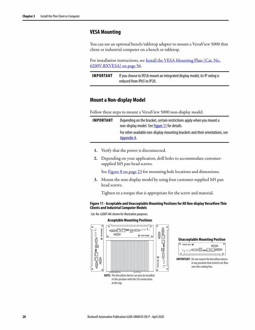
Follow these steps to mount a VersaView 5000 non-display model.
1. Verify that the power is disconnected.
2. Depending on your application, drill holes to accommodate customer-supplied M5 pan head screws.
See Figure 8 on page 23 for mounting hole locations and dimensions.
3. Mount the non-display model by using four customer-supplied M5 pan head screws.
Tighten to a torque that is appropriate for the screw and material.
Figure 11 - Acceptable and Unacceptable Mounting Positions for All Non-display VersaView Thin Clients and Industrial Computer Models
IMPORTANT If you choose to VESA mount an integrated display model, its IP rating is reduced from IP65 to IP20.
IMPORTANT Depending on the bracket, certain restrictions apply when you mount a non-display model. See Figure 11 for details.For other available non-display mounting brackets and their orientations, see Appendix A.
Cat. No. 6200T-NA shown for illustrative purposes.
NOTE: The VersaView device can also be installed in this position with the I/O connections at the top.
IMPORTANT: Do not mount the VersaView devicein any position that restricts air flowover the cooling fins.
Acceptable Mounting Positions
Unacceptable Mounting Position
28 Rockwell Automation Publication 6200-UM001D-EN-P - April 2020
Install the Thin Client or Computer Chapter 3
Connect Peripherals See Hardware Features on page 11 or page 14 for what ports are available to connect peripherals. Use the table below for accessories to connect peripherals to VersaView 5000 thin clients or industrial computers.
IMPORTANT For optimal performance, use only Rockwell Automation-approved active DisplayPort adapters.
Table 4 - Available Accessories for VersaView Thin Clients and Industrial Computers
Cat. Nos. Per Location Type
Category Cat. No. DescriptionNon-hazardous
Only
Non-hazardous and
Hazardous(2)
Mounting hardware
6200V-BXDIN DIN rail mounting kit 6200T-KB 6200P-NS3x16200P-NS3x1K6200P-NS3C66200T-NA6200T-NAK
6200V-BXDIN2 DIN rail mounting kit 6200T-BA —
6200V-BXLGCY Legacy mounting plate 6200T-KB 6200P-NS3x16200P-NS3x1K6200P-NS3C66200T-NA6200T-NAK
6200V-BXMACH Machine mounting bracket 6200T-KB 6200P-NS3x16200P-NS3x1K6200P-NS3C66200T-NA6200T-NAK
6200V-BXMACH2 Machine mounting bracket for ThinManager thin client multi-4K display models
6200T-RC6200T-RE
—
6200V-BXVESA VESA mounting plate 6200T-KB 6200P-NS3x16200P-NS3x1K6200P-NS3C66200T-NA6200T-NAK
6200V-BXVESA2 VESA mounting plate 6200T-BA —
6200V-BXWALL Bookshelf mounting plate 6200T-KB 6200P-NS3x16200P-NS3x1K6200P-NS3C66200T-NA6200T-NAK
6200V-BXWALL2 Bookshelf mounting plate 6200T-BA —
Cables, adapters, and I/O accessories
6200V-DPVGA2 DisplayPort to VGA active adapter All 6200P-NS3x16200P-NS3x1K6200P-NS3C66200T-NA6200T-NAK
6200V-DPDVI2 DisplayPort to DVI-D active adapter
6200V-DPHDMI4K DisplayPort to HDMI active adapter
6200V-DPCBL2M DisplayPort to DisplayPort cable, 2 m (6.5 ft) long
6200V-DVICBL2M DVI-D to DVI-D cable, 2 m (6.5 ft) long
6200V-MDP2HDMI4K Mini DisplayPort to HDMI adapter 6200T-RC6200T-RE
—
6200V-MDP2DP Mini DisplayPort to DisplayPort adapter
6200V-PLUGS Protective I/O port dust caps All 6200P-NS3x16200P-NS3x1K6200P-NS3C66200T-NA6200T-NAK
6200V-VGACBL2M VGA to VGA cable, 2 m (6.5 ft) long
6200V-USBCBL2M USB to USB touch screen cable, 2 m (6.5 ft) long
Rockwell Automation Publication 6200-UM001D-EN-P - April 2020 29

Chapter 3 Install the Thin Client or Computer
Protective I/O Port Dust Caps, Cat. No. 6200V-PLUGS
Protective I/O port dust caps are for hazardous locations where airborne chemicals or other particulates can damage exposed I/O ports and subsequently affect their reliability. An ordered kit supplies dust caps for each I/O port as detailed in Figure 1 on page 11 or Figure 4 on page 14.
The four VersaView 5000 models with conformal coating (Cat. Nos. 6200P-NS3A1K, 6200P-NS3B1K, 6200P-NS3C1K, and 6200T-NAK) are shipped with these protective I/O dust caps installed.
Power connection
6200V-MPS4 AC to 90 W, 24V DC power adapter(1) All except 6200T-BA
—
6200V-MPS5 Replacement AC to DC power adapter(1) 6200T-BA —
6200V-MPS6 AC to 40 W, 24V DC power adapter(1) 6200T-KB —
6200V-DCCONN DC power mating connector housing kit All except 6200T-BA 6200T-KB6200T-RC6200T-RE
6200P-NS3x16200P-NS3x1K6200P-NS3C66200T-NA6200T-NAK
6200V-DCCONN2 Replacement DC terminal block 6200T-KB6200T-RC6200T-RE
—
(1) Power adapters ship with a power cord that has an IEC 60320 C14 receptacle and a NEMA 5-15P three-prong plug for North American applications. Any IEC 60320 C13 power cord can be used for other international applications.
(2) Certain conditions apply; see the Arc Flash Hazard table on page 30.
Table 4 - Available Accessories for VersaView Thin Clients and Industrial Computers (continued)
Cat. Nos. Per Location Type
Category Cat. No. DescriptionNon-hazardous
Only
Non-hazardous and
Hazardous(2)
ARC FLASH HAZARD: Do not connect or disconnect any accessories to VersaView 5000 devices for hazardous locations unless power has been switched off and the area is known to be non-hazardous.Before power is switched on, verify that any adapter, cable, or power connection accessory is fully inserted in its port. For adapter and cable accessories, verify that latches are engaged, and any screws are fully engaged and tightened.Failure to do so could result in an electric arc that can cause an explosion in a hazardous location.
30 Rockwell Automation Publication 6200-UM001D-EN-P - April 2020
Install the Thin Client or Computer Chapter 3
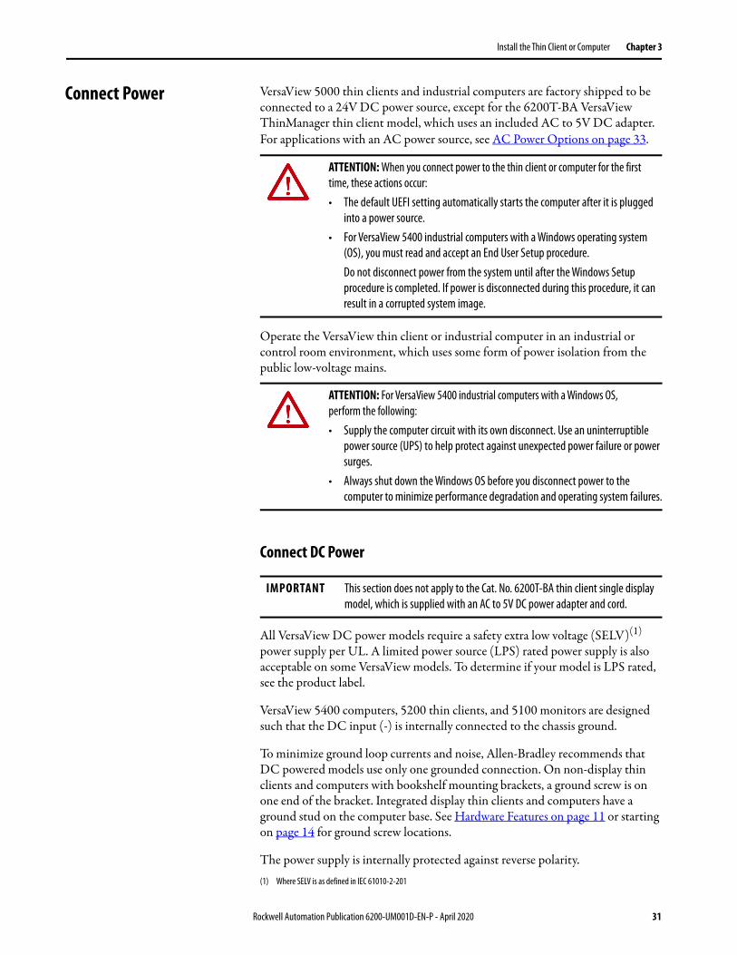
Connect Power VersaView 5000 thin clients and industrial computers are factory shipped to be connected to a 24V DC power source, except for the 6200T-BA VersaView ThinManager thin client model, which uses an included AC to 5V DC adapter. For applications with an AC power source, see AC Power Options on page 33.
Operate the VersaView thin client or industrial computer in an industrial or control room environment, which uses some form of power isolation from the public low-voltage mains.
Connect DC Power
All VersaView DC power models require a safety extra low voltage (SELV)(1) power supply per UL. A limited power source (LPS) rated power supply is also acceptable on some VersaView models. To determine if your model is LPS rated, see the product label.
VersaView 5400 computers, 5200 thin clients, and 5100 monitors are designed such that the DC input (-) is internally connected to the chassis ground.
To minimize ground loop currents and noise, Allen-Bradley recommends that DC powered models use only one grounded connection. On non-display thin clients and computers with bookshelf mounting brackets, a ground screw is on one end of the bracket. Integrated display thin clients and computers have a ground stud on the computer base. See Hardware Features on page 11 or starting on page 14 for ground screw locations.
The power supply is internally protected against reverse polarity.
ATTENTION: When you connect power to the thin client or computer for the first time, these actions occur:• The default UEFI setting automatically starts the computer after it is plugged
into a power source. • For VersaView 5400 industrial computers with a Windows operating system
(OS), you must read and accept an End User Setup procedure. Do not disconnect power from the system until after the Windows Setup procedure is completed. If power is disconnected during this procedure, it can result in a corrupted system image.
ATTENTION: For VersaView 5400 industrial computers with a Windows OS, perform the following:• Supply the computer circuit with its own disconnect. Use an uninterruptible
power source (UPS) to help protect against unexpected power failure or power surges.
• Always shut down the Windows OS before you disconnect power to the computer to minimize performance degradation and operating system failures.
IMPORTANT This section does not apply to the Cat. No. 6200T-BA thin client single display model, which is supplied with an AC to 5V DC power adapter and cord.
(1) Where SELV is as defined in IEC 61010-2-201
Rockwell Automation Publication 6200-UM001D-EN-P - April 2020 31
Chapter 3 Install the Thin Client or Computer
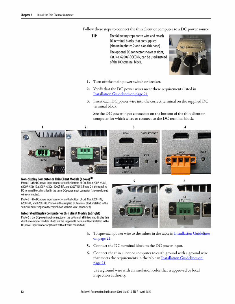
Follow these steps to connect the thin client or computer to a DC power source.
1. Turn off the main power switch or breaker.
2. Verify that the DC power wires meet these requirements listed in Installation Guidelines on page 21.
3. Insert each DC power wire into the correct terminal on the supplied DC terminal block.
See the DC power input connector on the bottom of the thin client or computer for which wires to connect to the DC terminal block.
4. Torque each power wire to the values in the table in Installation Guidelines on page 21.
5. Connect the DC terminal block to the DC power input.
6. Connect the thin client or computer to earth ground with a ground wire that meets the requirements in the table in Installation Guidelines on page 21.
Use a ground wire with an insulation color that is approved by local inspection authority.
TIP The following steps are to wire and attach DC terminal blocks that are supplied (shown in photos 2 and 4 on this page).The optional DC connector shown at right, Cat. No. 6200V-DCCONN, can be used instead of the DC terminal block.
Non-display Computer or Thin Client Models (above)(1)
Photo 1 is the DC power input connector on the bottom of Cat. Nos. 6200P-NS3x1, 6200P-NS3x1K, 6200P-NS3C6, 6200T-NA, and 6200T-NAK. Photo 2 is the supplied DC terminal block installed in the same DC power input connector (shown without wires connected).Photo 3 is the DC power input connector on the bottom of Cat. Nos. 6200T-KB, 6200T-RC, and 6200T-RE. Photo 4 is the supplied DC terminal block installed in the same DC power input connector (shown without wires connected).
Integrated Display Computer or thin client Models (at right)Photo 5 is the DC power input connector on the bottom of all integrated display thin client or computer models. Photo 6 is the supplied DC terminal block installed in the DC power input connector (shown without wires connected).
2 3 41
5 6
32 Rockwell Automation Publication 6200-UM001D-EN-P - April 2020
Install the Thin Client or Computer Chapter 3
7. Apply 24V DC power to the thin client or computer.
AC Power Options
The following options are available to convert AC to 24V DC power for VersaView 5000 thin clients or industrial computers, except for the 6200T-BA thin client single display model(1). These options must be ordered separately.
• An AC to 90 W, 24V DC power adapter and power cord (Cat. No. 6200V-MPS4)(2)
• An AC to 40 W, 24V DC power adapter and power cord(Cat. No. 6200V-MPS6)(2)
• Allen-Bradley® switched mode power supplies: https://ab.rockwellautomation.com/Power-Supplies/Switched-Mode-Power-Supplies
Both power adapters ship with a power cord that has an IEC 60320 C14 receptacle and a standard NEMA 5-15P three-prong plug for use in North America. Any IEC 60320 C13 power cord can be used for other international applications.
Follow these steps to connect a separately purchased AC to DC power adapter to an AC power source.
1. Connect the AC to DC power adapter to the DC power input on the computer. See Hardware Features on page 11 or page 14 for the DC power input location.
2. Connect the receptacle end of the power cord to the power adapter.
3. Connect the three-prong plug end of the power cord to an AC power source.
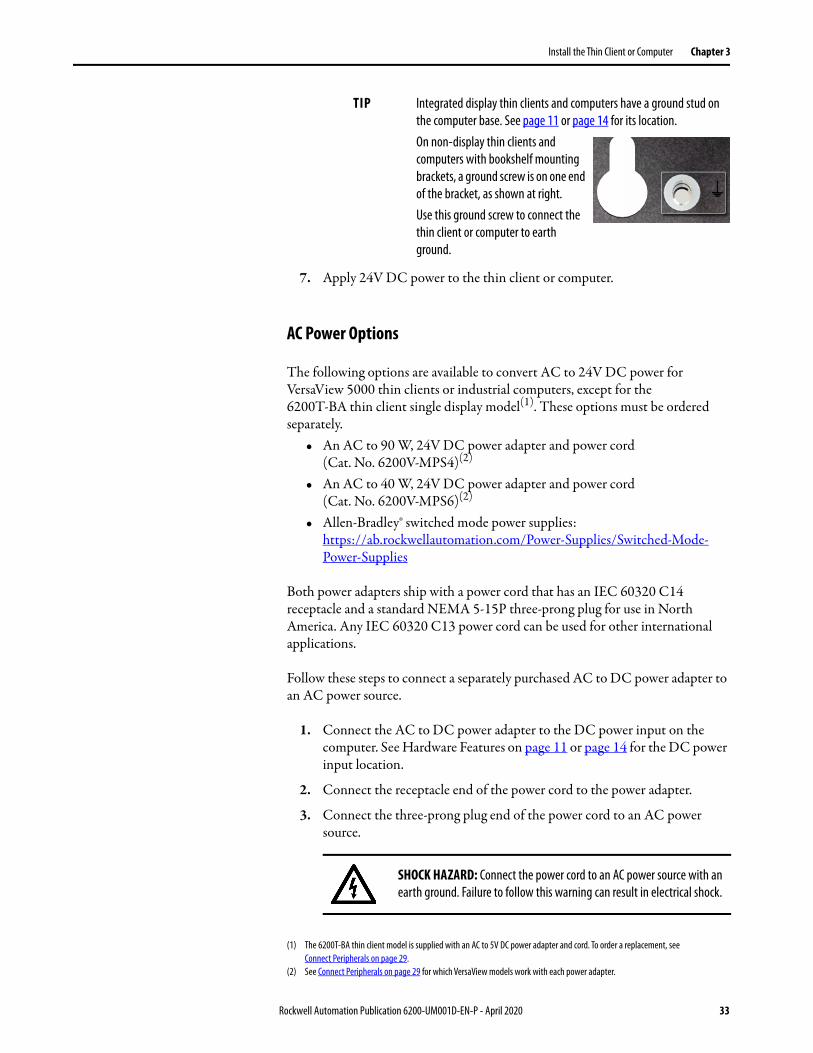
TIP Integrated display thin clients and computers have a ground stud on the computer base. See page 11 or page 14 for its location.On non-display thin clients and computers with bookshelf mounting brackets, a ground screw is on one end of the bracket, as shown at right.Use this ground screw to connect the thin client or computer to earth ground.
(1) The 6200T-BA thin client model is supplied with an AC to 5V DC power adapter and cord. To order a replacement, seeConnect Peripherals on page 29.
(2) See Connect Peripherals on page 29 for which VersaView models work with each power adapter.
SHOCK HAZARD: Connect the power cord to an AC power source with an earth ground. Failure to follow this warning can result in electrical shock.
Rockwell Automation Publication 6200-UM001D-EN-P - April 2020 33

Chapter 3 Install the Thin Client or Computer
Notes:
34 Rockwell Automation Publication 6200-UM001D-EN-P - April 2020
Chapter 4
Operate the Thin Client or Computer
Operating Guidelines Follow these operating guidelines for your VersaView® thin client or computer:• When the thin client or computer is panel mounted, operator access is
limited to the front of the thin client or computer, which includes the display and the touch screen.
• When the thin client or computer is mounted in an enclosure, keep the enclosure door closed during operation so dust and other airborne contamination do not infiltrate the thin client or computer. Open the door only for routine maintenance.
• Always use the proper power down procedures as required by your operating system, such as the Shut Down command in the Microsoft Windows operating system (OS).
• After you shut down the thin client or computer, do not apply power again until shutdown is complete.
Topic Page
Operating Guidelines 35
Touch Screen Precautions 36
Start the Thin Client or Computer 36
Restart the Thin Client or Computer 38
Shut Down the Thin Client or Computer 38
IMPORTANT Access to components behind the panel where the thin client or computer is installed is restricted to authorized and properly trained personnel.
SHOCK HAZARD: Do not operate the thin client or computer with the covers removed. An electric shock hazard exists. All covers are required to maintain EMI shield.
Rockwell Automation Publication 6200-UM001D-EN-P - April 2020 35
Chapter 4 Operate the Thin Client or Computer
Touch Screen Precautions
Touch Screen Driver Software
VersaView 5400 integrated display industrial computers are factory calibrated and do not need field calibration. They are shipped with a specialized touch screen driver (eGalaxTouch) and configuration utility that are optimized for single-touch mouse emulation applications such as FactoryTalk® View.
VersaView 5200 integrated display thin clients must be configured and calibrated via ThinManager® software. For more information on how to configure and calibrate, see https://thinmanager.com/support/manuals/.
WARNING: If the LCD screen darkens or if the backlight is not functioning properly, the screen may be difficult to read and use of this screen could result in a potentially hazardous outcome. Do not use the LCD touch screen under these circumstances. The design of the system must take into account the possibility of the LCD screen or LCD touch screen losing functionality and unable to be used to maintain or change control of the system. The touch screen shall not be the single point of control of critical functions and is not intended to replace an E-stop.Design of the system should follow all applicable code and good engineering practice. Factors to consider include the following:• The possibility of an unreadable LCD screen• The possibility of an inoperable touch screen• Unexpected communication errors or delays• Operator error in the control of the system• Proper use of E-stops and other safety practicesThe user shall provide means to achieve a safe state during anomalies and verify that the system has adequate redundancy for critical functions.Failure to follow these instructions can result in death, serious injury, or equipment damage.
IMPORTANT ThinManager software only supports single-touch operation.The USB touch screen driver module must be added to the terminal configuration.
36 Rockwell Automation Publication 6200-UM001D-EN-P - April 2020
Operate the Thin Client or Computer Chapter 4
Reinstall the Microsoft HID Driver on VersaView 5400 Integrated Display Computers
The factory-installed eGalaxTouch screen driver on VersaView 5400 integrated display industrial computers is for single touch applications. By default, the Windows OS on these computers report that ‘No Pen or Touch Input is available for this Display’ for multi-touch operation.
If you want the Windows OS to recognize the native Microsoft HID multi-touch driver, then you must first uninstall the eGalaxTouch screen driver.
To uninstall the eGalaxTouch screen driver, perform the following steps.
1. On your Windows task bar, click .
2. Click Control Panel.
3. In the Control Panel menu, click Programs and Features.
4. In the Programs list, find and highlight eGalaxTouch software.
5. Right-click the highlighted program name, and select Uninstall.
6. After you uninstall eGalaxTouch software, restart your computer.
Windows automatically installs the native Microsoft HID touch screen driver, and then reports the computer as having ‘Touch Input Available with 10 Touch Points.’
Start the Thin Client or Computer
Follow these steps to start your VersaView thin client or computer.
1. Make sure all necessary peripheral devices are connected to the corresponding I/O ports on the thin client or computer.
2. Make sure any connected components with separate power supplies (such as an external display) are turned on first.
TIP To reinstall the eGalaxTouch screen driver, access the Rockwell Automation® Product Compatibility and Download Center (PCDC) at https://compatibility.rockwellautomation.com/Pages/home.aspx.If you must reinstall the touch screen driver, the touch screen utility automatically detects the USB port used by the touch screen controller.
IMPORTANT The following steps apply to when the thin client or computer must be manually started. See Connect Power on page 31 for when power is applied to the thin client or computer for the first time.
Rockwell Automation Publication 6200-UM001D-EN-P - April 2020 37
Chapter 4 Operate the Thin Client or Computer
3. Install power to the power input of the thin client or computer.
AC powered models: See AC Power Options on page 33 for how to install an AC-to-DC power adapter to the DC power input on the thin client or computer.
DC powered models: See Connect DC Power on page 31 for how to install DC power to the DC power input on the thin client or computer.
4. Apply power to the thin client or computer.
5. Press the power switch on the thin client or computer.
See Hardware Features on page 11 or page 14 for the power switch location.
The thin client or industrial computer performs certain actions when it is started or reset. See Restart the Thin Client or Computer on page 38 for what is done.
If your system does not start or you notice other anomalies, refer to Troubleshoot the System starting on page 47.
Restart the Thin Client or Computer
Use any of the following methods to restart the thin client or computer.• From the Start menu, choose Restart.• Press Ctrl+Alt+Delete on an attached keyboard and click Restart.
During a restart, the thin client or computer does the following:• Clears the RAM.• Starts the POST.• Initializes peripheral devices such as drives and printers.• Loads the operating system (except for VersaView ThinManager® thin
client computers).
If a display is available, use it to view the progress of the POST, the initialization of accessory devices, and the startup dialogs for any operating system that is installed.
Shut Down the Thin Client or Computer
Use either of the following methods to shut down the thin client or computer.
Method Actions
Windows OS IMPORTANT: Applies only to VersaView 5400 integrated display industrial computers.With an attached mouse and keyboard, do one of the following.• Press Ctrl+Alt+Delete and click Shut Down.• From the Start menu, click or choose Shut Down.
Power switch Momentarily press the power switch to shut down the thin client or computer. See Hardware Features on page 11 or page 14 for the power switch location.
38 Rockwell Automation Publication 6200-UM001D-EN-P - April 2020
Chapter 5
Configure the UEFI (BIOS) Settings
Set-up Utility Overview The set-up utility is a hardware configuration program built into the universal extensible firmware interface (UEFI). In this chapter, UEFI replaces Basic Input/Output System (BIOS) to describe the system firmware except where BIOS is specifically used, such as on a graphical interface.
You can run the set-up utility to do the following: • Change the system configuration.• Set the time and date as part of a commissioning step.
• Redefine communication ports to help prevent any conflicts.• Read the current amount of system memory.• Change the boot drive order.• Set or change the password or make other changes to the security settings.
Topic Page
Set-up Utility Overview 39
Access the Set-up Utility 40
UEFI Overview 40
H/W Monitor 40
Security 40
Restore the OS Image 41
Upgrade to a New UEFI 42
TIP A commissioning step is one of the following situations:• When the thin client or computer is powered up initially• When the Windows OS image is restored (on VersaView® 5400
computers)• When the UEFI set-up utility is upgraded
Rockwell Automation Publication 6200-UM001D-EN-P - April 2020 39

Chapter 5 Configure the UEFI (BIOS) Settings
Access the Set-up Utility Follow these steps to access the set-up utility in your thin client or computer.
1. Start or restart your computer.
2. During POST, press F2 to access the UEFI set-up utility.
UEFI Overview The main tab is the default screen whenever you access the UEFI interface. Depending on the UEFI, there are other tabs with configurable menu items
Help Window
When you select a menu or submenu item, a corresponding help menu displays to the right of the item. As you toggle between menu items, the help menu updates automatically.
H/W Monitor You can view various hardware parameters from the H/W Monitor menu. It shows the temperature and system voltage measurements. This menu is beneficial to identify possible computer issues.
Security The Security tab of the UEFI set-up utility provides password protection for applications where security is preferred or needed.
You can set a supervisor password that is required to access the UEFI set-up utility. You can set a user password that is required for computer startup.
IMPORTANT An external keyboard must be connected to the computer to perform these steps.
UEFI for All Cat. Nos. Except 6200T-KB, 6200T-RC, and 6200T-RE UEFI for Cat. Nos. 6200T-KB, 6200T-RC, and 6200T-RE
Help Window Help Window
40 Rockwell Automation Publication 6200-UM001D-EN-P - April 2020
Configure the UEFI (BIOS) Settings Chapter 5
Restore the OS Image Perform the following steps to restore your computer with a backed-up OS image on an external USB storage drive.
1. Attach the following external peripherals to your computer:.• Display (for non-display computers)• USB Keyboard• USB drive (16 GB or larger)
2. Access the Rockwell Automation® PCDC website at https://compatibility.rockwellautomation.com/Pages/home.aspx.
3. On the home page, click Find Downloads.
4. On the Find Downloads page, use your computer model as the search criteria.
5. Follow the instructions on the PCDC site to find your OS image.
6. Download the OS Image file to your USB drive.
7. After the file downloads, restart the computer.
8. During POST, press F5 to access the Boot menu.
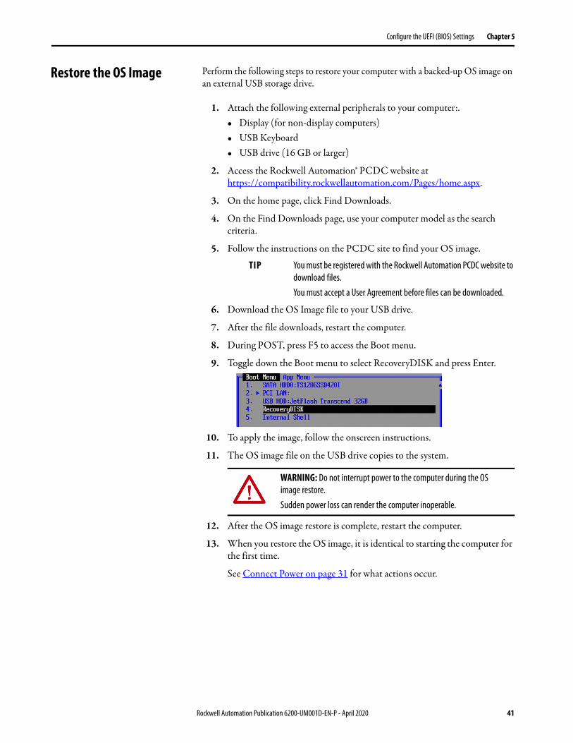
9. Toggle down the Boot menu to select RecoveryDISK and press Enter.
10. To apply the image, follow the onscreen instructions.
11. The OS image file on the USB drive copies to the system.
12. After the OS image restore is complete, restart the computer.
13. When you restore the OS image, it is identical to starting the computer for the first time.
See Connect Power on page 31 for what actions occur.
TIP You must be registered with the Rockwell Automation PCDC website to download files.You must accept a User Agreement before files can be downloaded.
WARNING: Do not interrupt power to the computer during the OS image restore.Sudden power loss can render the computer inoperable.
Rockwell Automation Publication 6200-UM001D-EN-P - April 2020 41

Chapter 5 Configure the UEFI (BIOS) Settings
Upgrade to a New UEFI Sometimes a new UEFI (BIOS) is released to enhance the performance of your computer or to correct a anomaly. In such cases, you can download BIOS upgrades at the Rockwell Automation PCDC website at https://compatibility.rockwellautomation.com/Pages/home.aspx. A USB drive upgrade is available.
For All VersaView 5000 ThinManager® Thin Client and Industrial Computers Except Cat. No. 6200T-BA
For instructions to upgrade the BIOS for Cat. No. 6200T-BA, see page 44.
To upgrade the BIOS for other VersaView 5000 ThinManager thin client and industrial computers, perform the following steps.
1. Attach the following external peripherals to your computer:• Display (for non-display computers)• USB keyboard• USB drive (1 GB or larger)
2. Access the Rockwell Automation PCDC website.
3. On the home page, click Find Downloads.
4. On the Find Downloads page, use your computer model as the search criteria.
5. Follow the instructions on the PCDC site to find your BIOS.
6. Download the BIOS file to your USB drive.
7. Open the file and extract the folder to the root directory of your USB drive.
8. After the folder is extracted, restart the computer.
9. During POST, press F5 to access the Boot menu.
TIP You must be registered with the Rockwell Automation PCDC website to download files.You must accept a User Agreement before files can be downloaded.
42 Rockwell Automation Publication 6200-UM001D-EN-P - April 2020
Configure the UEFI (BIOS) Settings Chapter 5
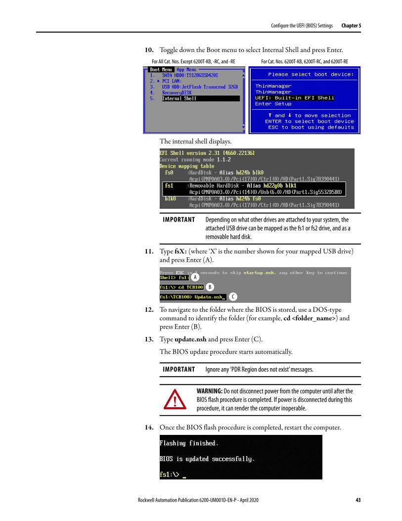
10. Toggle down the Boot menu to select Internal Shell and press Enter.
The internal shell displays.
11. Type fsX: (where ‘X’ is the number shown for your mapped USB drive) and press Enter (A).
12. To navigate to the folder where the BIOS is stored, use a DOS-type command to identify the folder (for example, cd <folder_name>) and press Enter (B).
13. Type update.nsh and press Enter (C).
The BIOS update procedure starts automatically.
14. Once the BIOS flash procedure is completed, restart the computer.
IMPORTANT Depending on what other drives are attached to your system, the attached USB drive can be mapped as the fs1 or fs2 drive, and as a removable hard disk.
IMPORTANT Ignore any ‘PDR Region does not exist’ messages.
WARNING: Do not disconnect power from the computer until after the BIOS flash procedure is completed. If power is disconnected during this procedure, it can render the computer inoperable.
For All Cat. Nos. Except 6200T-KB, -RC, and -RE For Cat. Nos. 6200T-KB, 6200T-RC, and 6200T-RE
A
B
C
Rockwell Automation Publication 6200-UM001D-EN-P - April 2020 43
Chapter 5 Configure the UEFI (BIOS) Settings
For VersaView 5200 ThinManager Thin Client Cat. No. 6200T-BA
To upgrade the BIOS for VersaView 5200 ThinManager thin client Cat. No. 6200T-BA, perform the following steps.
1. Attach the following external peripherals to your computer:• Display• USB keyboard• USB drive (1 GB or larger)
2. Access the Rockwell Automation PCDC website:https://compatibility.rockwellautomation.com/Pages/home.aspx
3. On the home page, click Find Downloads.
4. On the Find Downloads page, use your computer model (6200T-BA) as the search criteria.
5. Follow the instructions on the PCDC site to find your BIOS.
6. Download the BIOS file to your USB drive.
7. Open the file and extract the folder to the root directory of your USB drive.
8. After the folder is extracted, restart the computer.
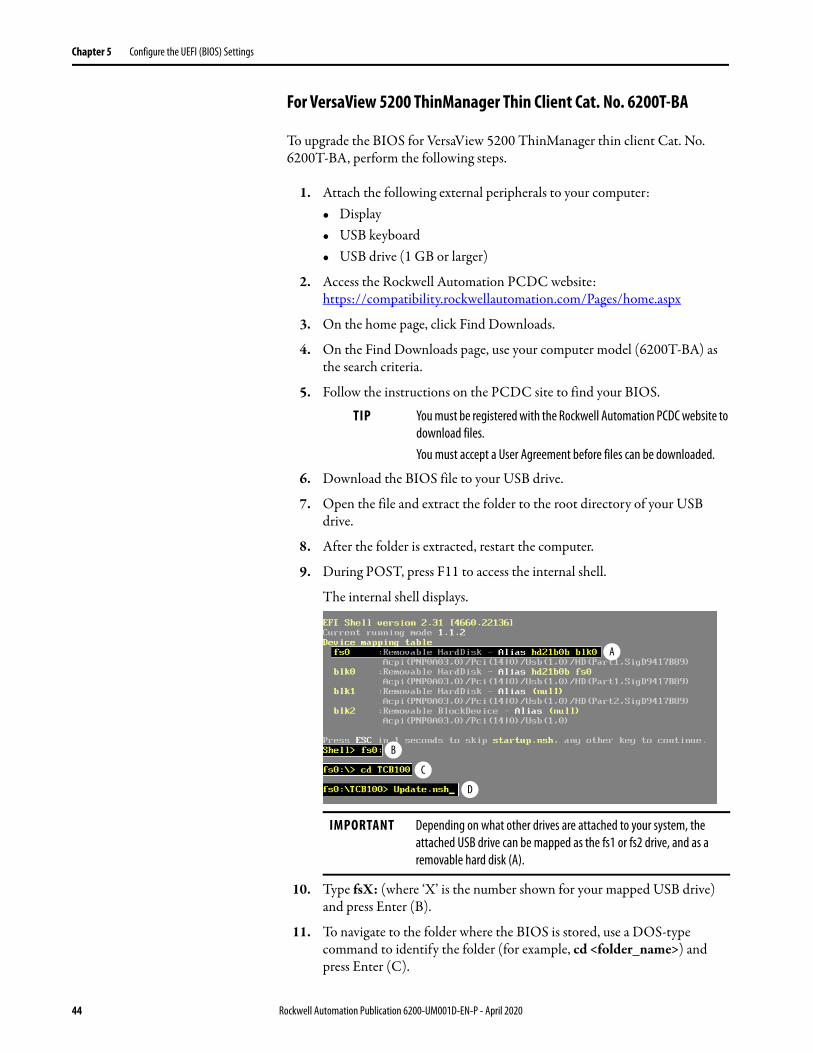
9. During POST, press F11 to access the internal shell.
The internal shell displays.
10. Type fsX: (where ‘X’ is the number shown for your mapped USB drive) and press Enter (B).
11. To navigate to the folder where the BIOS is stored, use a DOS-type command to identify the folder (for example, cd <folder_name>) and press Enter (C).
TIP You must be registered with the Rockwell Automation PCDC website to download files.You must accept a User Agreement before files can be downloaded.
IMPORTANT Depending on what other drives are attached to your system, the attached USB drive can be mapped as the fs1 or fs2 drive, and as a removable hard disk (A).
A
B
C
D
44 Rockwell Automation Publication 6200-UM001D-EN-P - April 2020
Configure the UEFI (BIOS) Settings Chapter 5
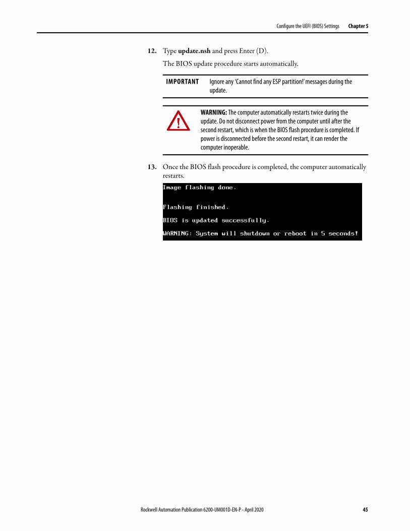
12. Type update.nsh and press Enter (D).
The BIOS update procedure starts automatically.
13. Once the BIOS flash procedure is completed, the computer automatically restarts.
IMPORTANT Ignore any ‘Cannot find any ESP partition!’ messages during the update.
WARNING: The computer automatically restarts twice during the update. Do not disconnect power from the computer until after the second restart, which is when the BIOS flash procedure is completed. If power is disconnected before the second restart, it can render the computer inoperable.
Rockwell Automation Publication 6200-UM001D-EN-P - April 2020 45

Chapter 5 Configure the UEFI (BIOS) Settings
Notes:
46 Rockwell Automation Publication 6200-UM001D-EN-P - April 2020
Chapter 6
Troubleshoot the System
Hardware (H/W) Monitoring
The built-in hardware monitor of the computer tracks the operating threshold levels of the voltage and temperature sensors.
Follow these steps to determine whether an operating threshold has been reached.
1. Shut down the computer by using the appropriate method for the installed operating system.
See Shut Down the Thin Client or Computer on page 38 for more information.
2. Apply power to the computer.
3. During POST, press F2 to access the UEFI set-up utility:
4. On the Main screen, click Advanced.
5. On the Advanced screen, click H/W Monitor.
Use this menu to determine if there is an issue with internal voltages or component temperatures.
Topic Page
Hardware (H/W) Monitoring 47
Troubleshooting 48
Load the System Defaults 48
Ship or Transport the Computer 49
Dispose of the Computer 49
Rockwell Automation Publication 6200-UM001D-EN-P - April 2020 47
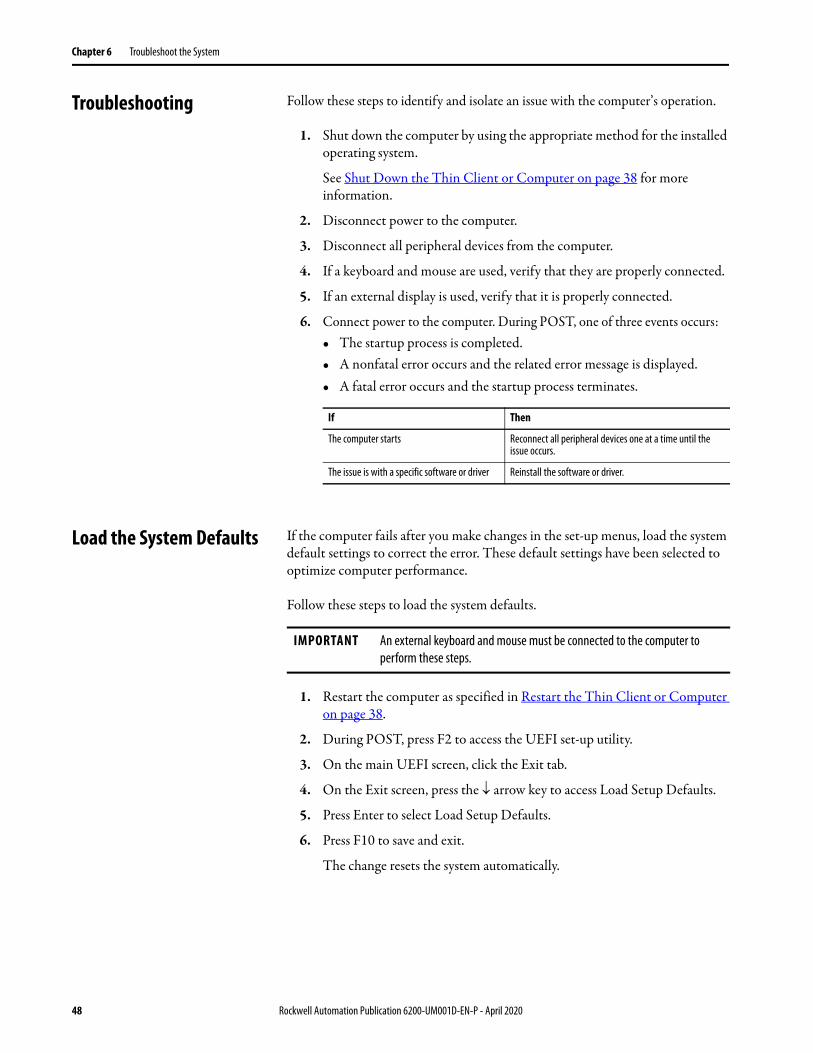
Chapter 6 Troubleshoot the System
Troubleshooting Follow these steps to identify and isolate an issue with the computer’s operation.
1. Shut down the computer by using the appropriate method for the installed operating system.
See Shut Down the Thin Client or Computer on page 38 for more information.
2. Disconnect power to the computer.
3. Disconnect all peripheral devices from the computer.
4. If a keyboard and mouse are used, verify that they are properly connected.
5. If an external display is used, verify that it is properly connected.
6. Connect power to the computer. During POST, one of three events occurs:• The startup process is completed.• A nonfatal error occurs and the related error message is displayed. • A fatal error occurs and the startup process terminates.
Load the System Defaults If the computer fails after you make changes in the set-up menus, load the system default settings to correct the error. These default settings have been selected to optimize computer performance.
Follow these steps to load the system defaults.
1. Restart the computer as specified in Restart the Thin Client or Computer on page 38.
2. During POST, press F2 to access the UEFI set-up utility.
3. On the main UEFI screen, click the Exit tab.
4. On the Exit screen, press the arrow key to access Load Setup Defaults.
5. Press Enter to select Load Setup Defaults.
6. Press F10 to save and exit.
The change resets the system automatically.
If Then
The computer starts Reconnect all peripheral devices one at a time until the issue occurs.
The issue is with a specific software or driver Reinstall the software or driver.
IMPORTANT An external keyboard and mouse must be connected to the computer to perform these steps.
48 Rockwell Automation Publication 6200-UM001D-EN-P - April 2020

Troubleshoot the System Chapter 6
Ship or Transport the Computer
If you must ship the computer via common carrier or otherwise transport it to another location for service or any other reason, you must first uninstall the computer and place it in its original packing material.
Dispose of the Computer
You cannot dispose of computer equipment like other waste material. Most computers and monitors contain heavy metals that can contaminate the earth. Therefore, check with local health and sanitation agencies for ways to safely dispose of computer equipment.
When a storage drive is part of what you plan to dispose, then permanently erase any data on it or destroy the drive before it is disposed.
ATTENTION: Do not ship or transport the computer when it is installed in a machine, panel, or rack. To avoid damage to the computer, you must uninstall the computer and place it in its original packing material before you ship it. Rockwell Automation is not responsible for damage to a computer that is shipped or transported while installed in a machine, panel, or rack.
At the end of its life, collect the computer separately from any unsorted municipal waste.
Rockwell Automation Publication 6200-UM001D-EN-P - April 2020 49

Chapter 6 Troubleshoot the System
Notes:
50 Rockwell Automation Publication 6200-UM001D-EN-P - April 2020
Chapter 7
Clean the Thin Client or Computer
Clean the Thin Client or Computer
To maintain your computer, it is important to clean the display, cooling fins, and vent holes, and to remove grease or paint.
Topic Page
Clean the Thin Client or Computer 51
IMPORTANT VersaView® 5000 ThinManager® thin clients and industrial computers resist the following chemicals:• Alcohol (methyl, ethyl, or isopropyl)• Ammonia (10% dilute solution)• Automatic transmission fluid• Bleach• Commercial glass cleaners• Diesel fuel• Gasoline (unleaded)• Oil (hydraulic or motor)• Silicone-based lubricant
Rockwell Automation Publication 6200-UM001D-EN-P - April 2020 51
Chapter 7 Clean the Thin Client or Computer
Clean the Integrated Display
Perform the following steps to clean a display (applies to VersaView 5000 ThinManager thin clients and industrial computers with an integrated display).
1. Disconnect power from the computer at the power source.
2. Clean the display with a mild soap and a clean sponge or a soft cloth.
3. Dry the display with a chamois or moist cellulose sponge to avoid water spots.
Clean the Air Openings and Cooling Fins
Perform the following steps to clean all VersaView 5000 ThinManager thin clients and industrial computers.
1. Disconnect power from the computer at the power source.
2. Disconnect all peripheral devices from the computer.
3. Vacuum dust and debris from the vent holes on the sides of the integrated display computers, and from the cooling fins on the chassis of all computers.
Remove stubborn dirt on the cooling fins with a mild detergent and soft cloth.
Remove Paint and Grease from Bezel
Perform the following steps to remove paint and grease from the bezel of computers properly mounted in IP65 enclosures.
1. Remove paint splashes and grease by rubbing lightly with isopropyl alcohol.
2. Use a mild soap or detergent solution to remove residue.
3. Rinse with clean water.
ATTENTION: Since the display is a touch screen, it is possible for screen objects to activate during equipment wash-downs if the computer is turned on.
ATTENTION: Use of abrasive cleansers, solvents, and high-pressure washes can damage the display window. Do not scrub or use brushes.
ATTENTION: Make sure the isopropyl alcohol does not come in contact with the equipment labels. Alcohol can cause the label printing to smear.
52 Rockwell Automation Publication 6200-UM001D-EN-P - April 2020
Appendix A
Install Accessories
Available Accessories You can view a list of accessories at https://ab.rockwellautomation.com/Computers/Integrated-Display-Computers/6200-VersaView-5400.
Review the specifications of a new component before you install it to verify that it is compatible with the computer. Record the model, serial number, and any other pertinent information of new components for future reference.
Disconnect Power There is line voltage input to any power supply adapters. Disconnect all power to the computer before you install or remove components.
Topic Page
Available Accessories 53
Disconnect Power 53
Electrostatic Discharge Precautions 54
Pre-configuration 54
Post-configuration 55
Required Tools 55
Replace a Factory-installed Bookshelf Mounting Plate (Cat. No. 6200V-BXWALL)
55
Install the VESA Mounting Plate (Cat. No. 6200V-BXVESA) 56
Install the DIN Rail Mounting Kit (Cat. No. 6200V-BXDIN) 59
Install the Machine Mounting Bracket Kit (Cat. No. 6200V-BXMACH) 62
Install the Legacy Mounting Plate (Cat. No. 6200V-BXLGCY) 66
IMPORTANT We recommend that you use only Allen-Bradley® approved accessories.
SHOCK HAZARD: Do not disconnect equipment unless power has been switched off and the area is known to be non-hazardous. Failure to disconnect power can result in severe electrical shock to an individual or damage to the computer.
Rockwell Automation Publication 6200-UM001D-EN-P - April 2020 53
Appendix A Install Accessories
Electrostatic Discharge Precautions
Follow these ESD precautions:• Transport the computer and replacement parts in static-safe containers,
such as conductive tubes, bags, or boxes.• Keep electrostatic-sensitive parts in their containers until they arrive at the
designated static-free work area.• Cover the designated work area with approved static-dissipating material:
– Use an anti-static wriststrap connected to the work surface.– Use properly grounded tools and equipment.
• Keep the designated work area free of nonconductive materials, such as ordinary plastic assembly aids and foam packing.
• Avoid touching pins, leads, or circuitry.• Always hold components with a printed circuit board (PCB) by its edges
and place it with the assembly side down.
Pre-configuration
Follow these steps before you remove or install a hardware component.
1. Shut down the computer and all peripherals that are connected to it.
2. Disconnect all cables from power outlets to avoid exposure to high energy levels.
If necessary, label each cable to expedite reassembly.
3. Disconnect all peripheral cables from the bottom I/O ports.
4. If the computer is table or wall mounted, loosen the mounting screws.
Remove the computer from its mounting.
ATTENTION: Electrostatic discharge (ESD) can damage static-sensitive devices or microcircuitry:• Disconnect all power before you work on the computer as detailed in
Disconnect Power on page 53.• Observe proper packaging and grounding techniques to help prevent damage.
ATTENTION: Make sure to read and understand all installation and removal procedures before you configure the computer hardware.
54 Rockwell Automation Publication 6200-UM001D-EN-P - April 2020
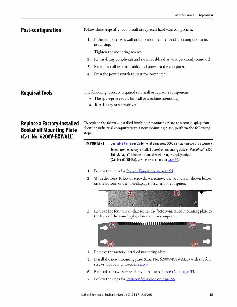
Install Accessories Appendix A
Post-configuration Follow these steps after you install or replace a hardware component.
1. If the computer was wall or table mounted, reinstall the computer to its mounting.
Tighten the mounting screws.
2. Reinstall any peripherals and system cables that were previously removed.
3. Reconnect all external cables and power to the computer.
4. Press the power switch to start the computer.
Required Tools The following tools are required to install or replace a component:• The appropriate tools for wall or machine mounting• Torx 10 key or screwdriver
Replace a Factory-installed Bookshelf Mounting Plate (Cat. No. 6200V-BXWALL)
To replace the factory-installed bookshelf mounting plate to a non-display thin client or industrial computer with a new mounting plate, perform the following steps.
1. Follow the steps for Pre-configuration on page 54.
2. With the Torx 10 key or screwdriver, remove the two screws shown below on the bottom of the non-display thin client or computer.
3. Remove the four screws that secure the factory-installed mounting plate to the back of the non-display thin client or computer.
4. Remove the factory-installed mounting plate.
5. Install the new mounting plate (Cat. No. 6200V-BXWALL) with the four screws that you removed in step 3.
6. Reinstall the two screws that you removed in step 2 on page 55.
7. Follow the steps for Post-configuration on page 55.
IMPORTANT See Table 4 on page 29 for what VersaView 5000 devices can use this accessory.To replace the factory-installed bookshelf mounting plate on VersaView® 5200 ThinManager® thin client computer with single display output (Cat. No. 6200T-BA), see the instructions on page 56.
Rockwell Automation Publication 6200-UM001D-EN-P - April 2020 55
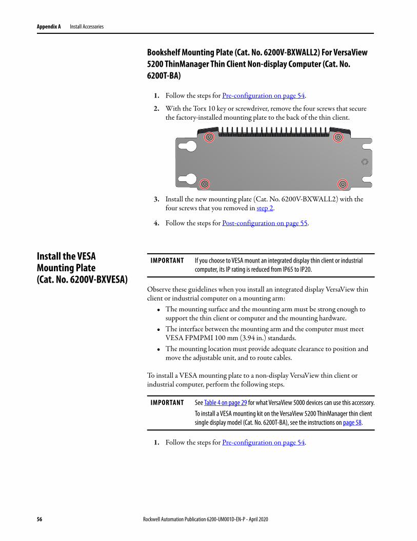
Appendix A Install Accessories
Bookshelf Mounting Plate (Cat. No. 6200V-BXWALL2) For VersaView 5200 ThinManager Thin Client Non-display Computer (Cat. No. 6200T-BA)
1. Follow the steps for Pre-configuration on page 54.
2. With the Torx 10 key or screwdriver, remove the four screws that secure the factory-installed mounting plate to the back of the thin client.
3. Install the new mounting plate (Cat. No. 6200V-BXWALL2) with the four screws that you removed in step 2.
4. Follow the steps for Post-configuration on page 55.
Install the VESA Mounting Plate (Cat. No. 6200V-BXVESA)
Observe these guidelines when you install an integrated display VersaView thin client or industrial computer on a mounting arm:
• The mounting surface and the mounting arm must be strong enough to support the thin client or computer and the mounting hardware.
• The interface between the mounting arm and the computer must meet VESA FPMPMI 100 mm (3.94 in.) standards.
• The mounting location must provide adequate clearance to position and move the adjustable unit, and to route cables.
To install a VESA mounting plate to a non-display VersaView thin client or industrial computer, perform the following steps.
1. Follow the steps for Pre-configuration on page 54.
IMPORTANT If you choose to VESA mount an integrated display thin client or industrial computer, its IP rating is reduced from IP65 to IP20.
IMPORTANT See Table 4 on page 29 for what VersaView 5000 devices can use this accessory.To install a VESA mounting kit on the VersaView 5200 ThinManager thin client single display model (Cat. No. 6200T-BA), see the instructions on page 58.
56 Rockwell Automation Publication 6200-UM001D-EN-P - April 2020
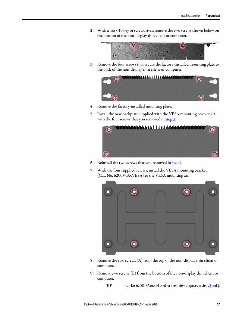
Install Accessories Appendix A
2. With a Torx 10 key or screwdriver, remove the two screws shown below on the bottom of the non-display thin client or computer.
3. Remove the four screws that secure the factory-installed mounting plate to the back of the non-display thin client or computer.
4. Remove the factory-installed mounting plate.
5. Install the new backplate supplied with the VESA mounting bracket kit with the four screws that you removed in step 3.
6. Reinstall the two screws that you removed in step 2.
7. With the four supplied screws, install the VESA mounting bracket (Cat. No. 6200V-BXVESA) to the VESA mounting arm.
8. Remove the two screws (A) from the top of the non-display thin client or computer.
9. Remove two screws (B) from the bottom of the non-display thin client or computer.
TIP Cat. No. 6200T-NA model used for illustrative purposes in steps 8 and 9.
Rockwell Automation Publication 6200-UM001D-EN-P - April 2020 57
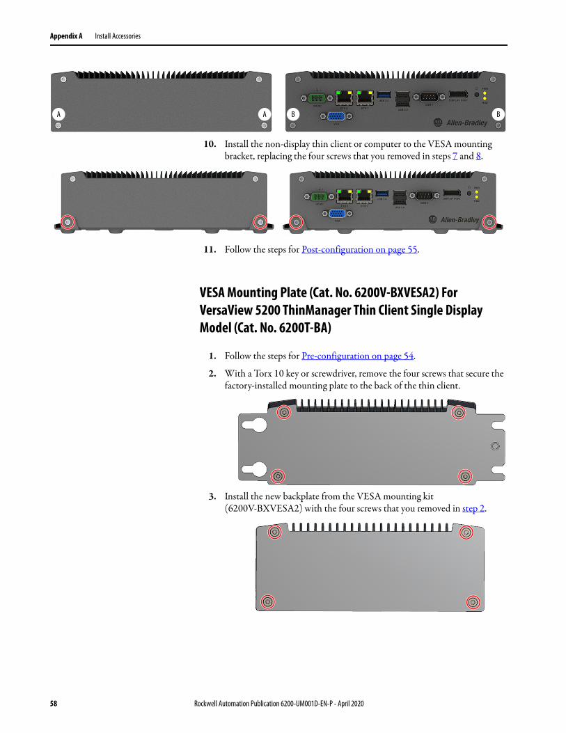
Appendix A Install Accessories
10. Install the non-display thin client or computer to the VESA mounting bracket, replacing the four screws that you removed in steps 7 and 8.
11. Follow the steps for Post-configuration on page 55.
VESA Mounting Plate (Cat. No. 6200V-BXVESA2) For VersaView 5200 ThinManager Thin Client Single Display Model (Cat. No. 6200T-BA)
1. Follow the steps for Pre-configuration on page 54.
2. With a Torx 10 key or screwdriver, remove the four screws that secure the factory-installed mounting plate to the back of the thin client.
3. Install the new backplate from the VESA mounting kit (6200V-BXVESA2) with the four screws that you removed in step 2.
A A B B
58 Rockwell Automation Publication 6200-UM001D-EN-P - April 2020

Install Accessories Appendix A
4. With the four supplied screws, install the VESA mounting bracket (Cat. No. 6200V-BXVESA2) to the VESA mounting arm.
5. Remove the two screws (A) from the top of the thin client.
6. Remove the two screws (B) from the bottom of the thin client.
7. Install the thin client to the VESA mounting bracket with the four screws that you removed in steps 5 and 6.
8. Follow the steps for Post-configuration on page 55.
Install the DIN Rail Mounting Kit (Cat. No. 6200V-BXDIN)
To install a DIN rail mounting kit on a non-display VersaView ThinManager thin client or industrial computer), perform the following steps.
1. Follow the steps for Pre-configuration on page 54.
A A B B
IMPORTANT See Table 4 on page 29 for what VersaView 5000 devices can use this accessory.To install a DIN rail mounting kit on the VersaView 5200 ThinManager thin client single display model (Cat. No. 6200T-BA), see the instructions on page 61.
Rockwell Automation Publication 6200-UM001D-EN-P - April 2020 59
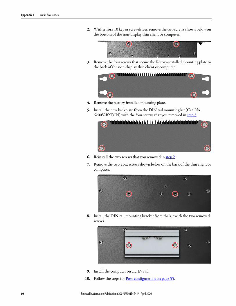
Appendix A Install Accessories
2. With a Torx 10 key or screwdriver, remove the two screws shown below on the bottom of the non-display thin client or computer.
3. Remove the four screws that secure the factory-installed mounting plate to the back of the non-display thin client or computer.
4. Remove the factory-installed mounting plate.
5. Install the new backplate from the DIN rail mounting kit (Cat. No. 6200V-BXDIN) with the four screws that you removed in step 3.
6. Reinstall the two screws that you removed in step 2.
7. Remove the two Torx screws shown below on the back of the thin client or computer.
8. Install the DIN rail mounting bracket from the kit with the two removed screws.
9. Install the computer on a DIN rail.
10. Follow the steps for Post-configuration on page 55.
60 Rockwell Automation Publication 6200-UM001D-EN-P - April 2020
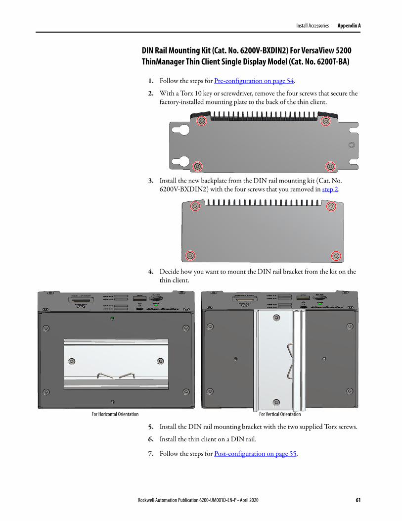
Install Accessories Appendix A
DIN Rail Mounting Kit (Cat. No. 6200V-BXDIN2) For VersaView 5200 ThinManager Thin Client Single Display Model (Cat. No. 6200T-BA)
1. Follow the steps for Pre-configuration on page 54.
2. With a Torx 10 key or screwdriver, remove the four screws that secure the factory-installed mounting plate to the back of the thin client.
3. Install the new backplate from the DIN rail mounting kit (Cat. No. 6200V-BXDIN2) with the four screws that you removed in step 2.
4. Decide how you want to mount the DIN rail bracket from the kit on the thin client.
5. Install the DIN rail mounting bracket with the two supplied Torx screws.
6. Install the thin client on a DIN rail.
7. Follow the steps for Post-configuration on page 55.
For Horizontal Orientation For Vertical Orientation
Rockwell Automation Publication 6200-UM001D-EN-P - April 2020 61
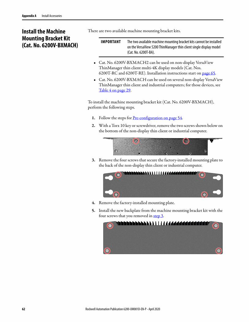
Appendix A Install Accessories
Install the Machine Mounting Bracket Kit(Cat. No. 6200V-BXMACH)
There are two available machine mounting bracket kits.
• Cat. No. 6200V-BXMACH2 can be used on non-display VersaView ThinManager thin client multi-4K display models (Cat. Nos. 6200T-RC and 6200T-RE). Installation instructions start on page 65.
• Cat. No. 6200V-BXMACH can be used on several non-display VersaView ThinManager thin client and industrial computers; for those devices, see Table 4 on page 29.
To install the machine mounting bracket kit (Cat. No. 6200V-BXMACH), perform the following steps.
1. Follow the steps for Pre-configuration on page 54.
2. With a Torx 10 key or screwdriver, remove the two screws shown below on the bottom of the non-display thin client or industrial computer.
3. Remove the four screws that secure the factory-installed mounting plate to the back of the non-display thin client or industrial computer.
4. Remove the factory-installed mounting plate.
5. Install the new backplate from the machine mounting bracket kit with the four screws that you removed in step 3.
IMPORTANT The two available machine mounting bracket kits cannot be installed on the VersaView 5200 ThinManager thin client single display model (Cat. No. 6200T-BA).
62 Rockwell Automation Publication 6200-UM001D-EN-P - April 2020
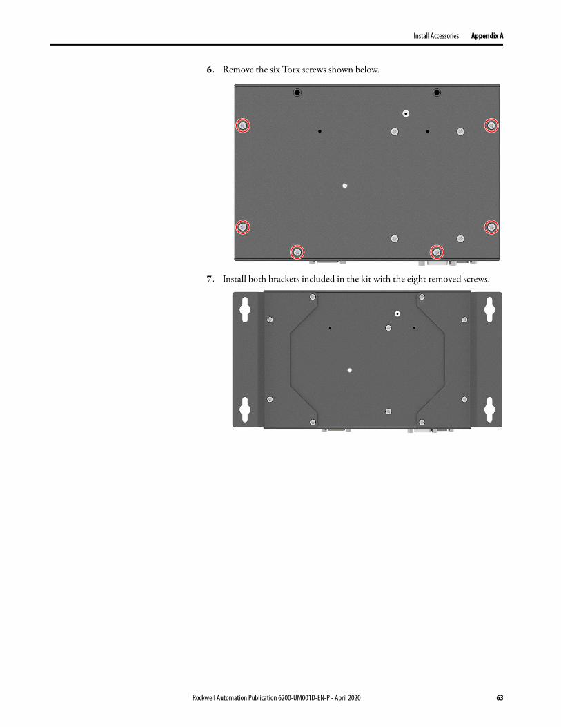
Install Accessories Appendix A
6. Remove the six Torx screws shown below.
7. Install both brackets included in the kit with the eight removed screws.
Rockwell Automation Publication 6200-UM001D-EN-P - April 2020 63
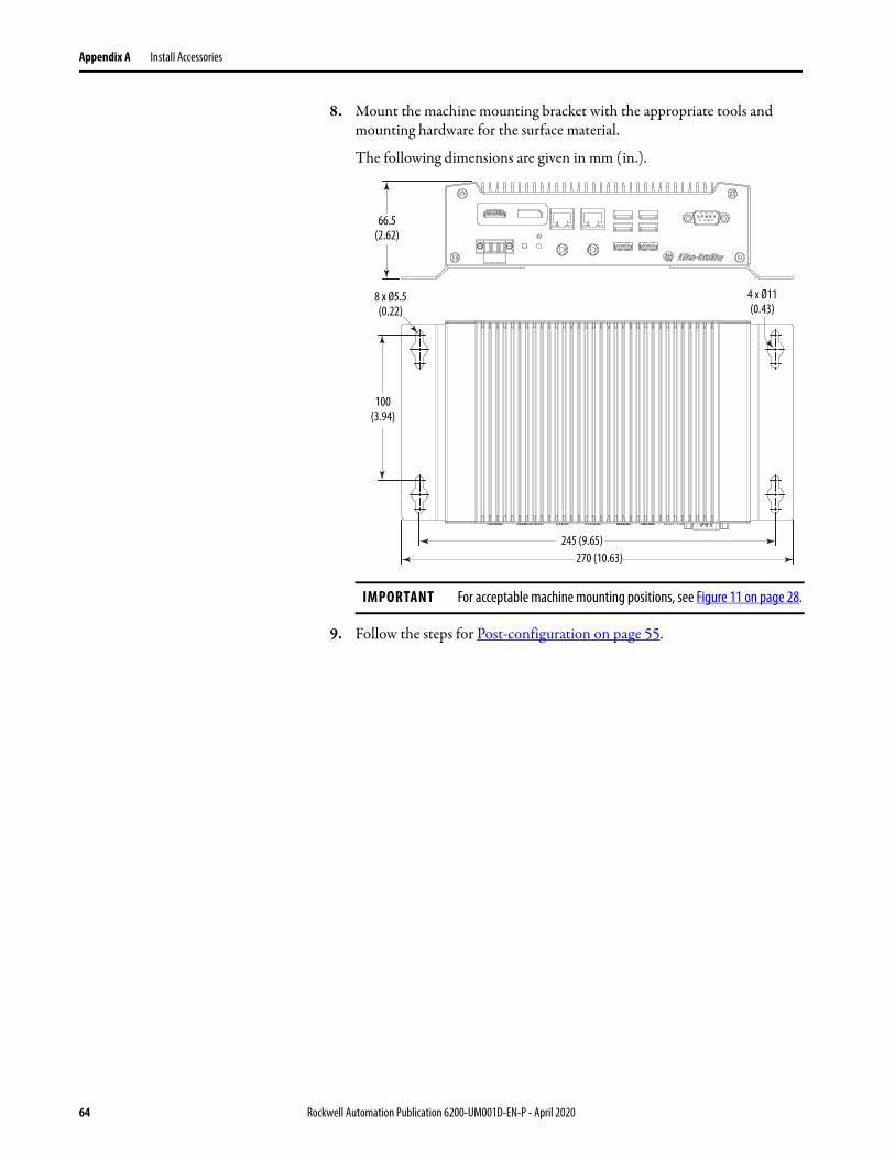
Appendix A Install Accessories
8. Mount the machine mounting bracket with the appropriate tools and mounting hardware for the surface material.
The following dimensions are given in mm (in.).
9. Follow the steps for Post-configuration on page 55.
IMPORTANT For acceptable machine mounting positions, see Figure 11 on page 28.
8 x Ø5.5 (0.22)
245 (9.65)270 (10.63)
100 (3.94)
66.5 (2.62)
4 x Ø11 (0.43)
64 Rockwell Automation Publication 6200-UM001D-EN-P - April 2020
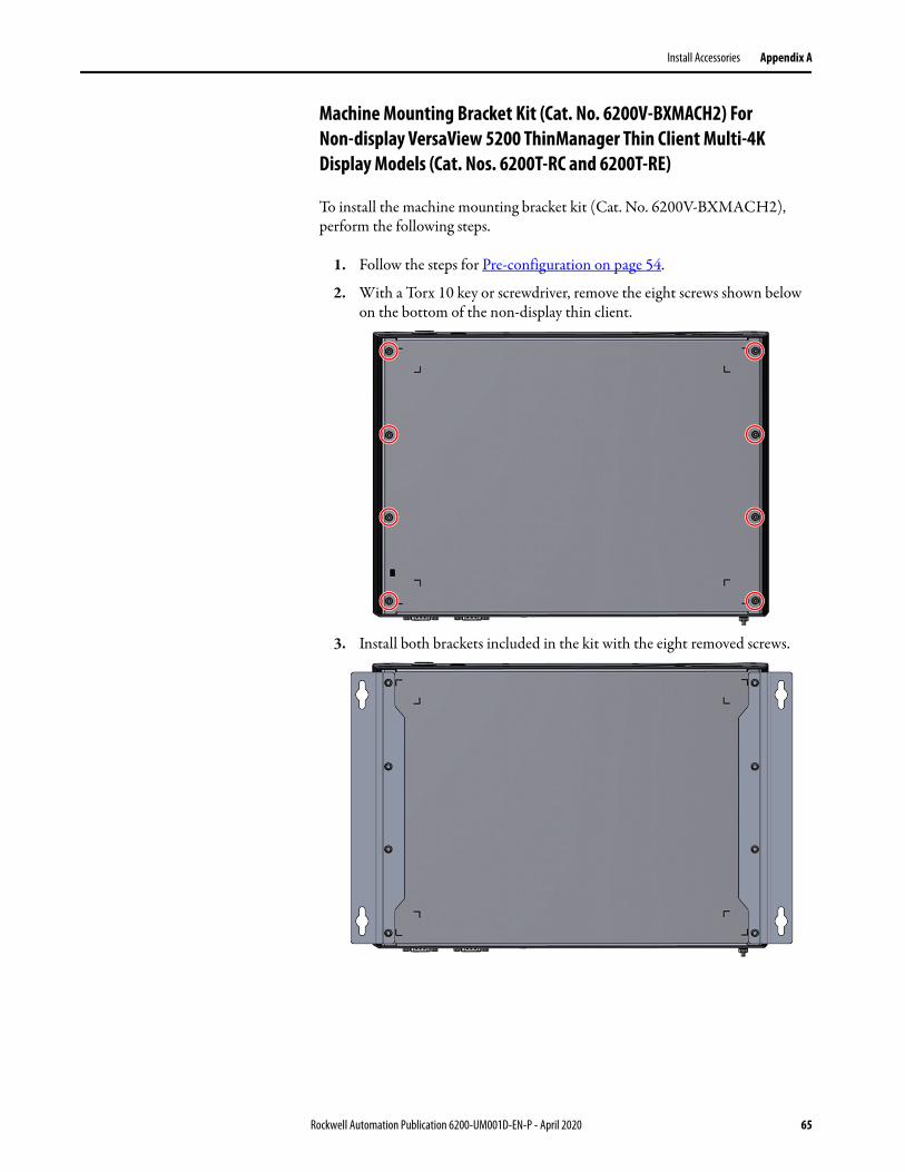
Install Accessories Appendix A
Machine Mounting Bracket Kit (Cat. No. 6200V-BXMACH2) For Non-display VersaView 5200 ThinManager Thin Client Multi-4K Display Models (Cat. Nos. 6200T-RC and 6200T-RE)
To install the machine mounting bracket kit (Cat. No. 6200V-BXMACH2), perform the following steps.
1. Follow the steps for Pre-configuration on page 54.
2. With a Torx 10 key or screwdriver, remove the eight screws shown below on the bottom of the non-display thin client.
3. Install both brackets included in the kit with the eight removed screws.
Rockwell Automation Publication 6200-UM001D-EN-P - April 2020 65

Appendix A Install Accessories
4. Mount the machine mounting bracket with the appropriate tools and mounting hardware for the surface material.
The following dimensions are given in mm (in.).
5. Follow the steps for Post-configuration on page 55.
Install the Legacy Mounting Plate(Cat. No. 6200V-BXLGCY)
Install a legacy mounting plate when a non-display VersaView ThinManager thin client or industrial computer replaces an Allen-Bradley® 6155R compact non-display computer.
There are several non-display VersaView ThinManager thin client and industrial computers that can use this mounting plate; for those devices, see Table 4 on page 29.
The legacy mounting plate reuses the mounting holes for the 6155R compact non-display computer, and reuses the mounting hardware.
IMPORTANT For acceptable machine mounting positions, see Figure 11 on page 28.
8 x Ø5.5 (0.22)
200 (7.87)
80.4 (3.17)
4 x Ø11 (0.43)
370 (14.57)
390 (15.35)
240 (9.45)
IMPORTANT The legacy mounting plate cannot be installed on the VersaView 5200 ThinManager thin client single display model (Cat. No. 6200T-BA).
66 Rockwell Automation Publication 6200-UM001D-EN-P - April 2020
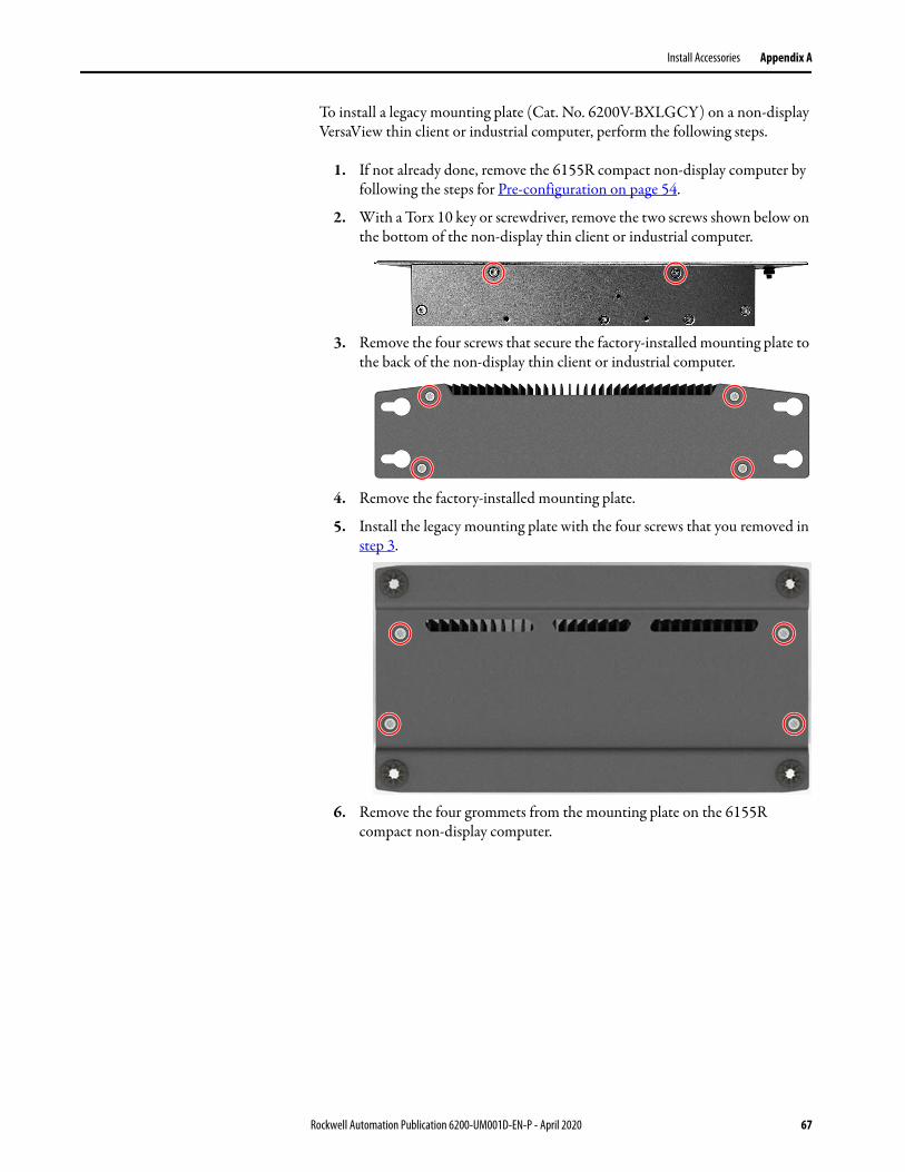
Install Accessories Appendix A
To install a legacy mounting plate (Cat. No. 6200V-BXLGCY) on a non-display VersaView thin client or industrial computer, perform the following steps.
1. If not already done, remove the 6155R compact non-display computer by following the steps for Pre-configuration on page 54.
2. With a Torx 10 key or screwdriver, remove the two screws shown below on the bottom of the non-display thin client or industrial computer.
3. Remove the four screws that secure the factory-installed mounting plate to the back of the non-display thin client or industrial computer.
4. Remove the factory-installed mounting plate.
5. Install the legacy mounting plate with the four screws that you removed in step 3.
6. Remove the four grommets from the mounting plate on the 6155R compact non-display computer.
Rockwell Automation Publication 6200-UM001D-EN-P - April 2020 67
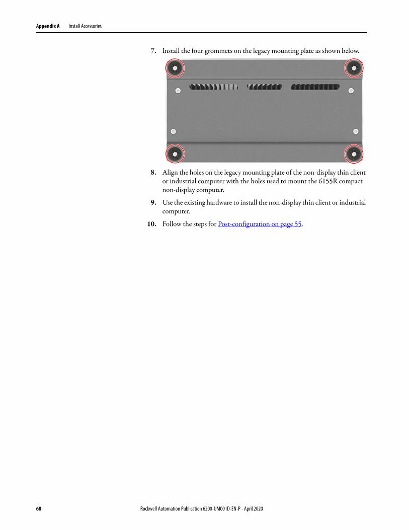
Appendix A Install Accessories
7. Install the four grommets on the legacy mounting plate as shown below.
8. Align the holes on the legacy mounting plate of the non-display thin client or industrial computer with the holes used to mount the 6155R compact non-display computer.
9. Use the existing hardware to install the non-display thin client or industrial computer.
10. Follow the steps for Post-configuration on page 55.
68 Rockwell Automation Publication 6200-UM001D-EN-P - April 2020
Index
Index Aaccessories 53
BBIOS Setup utility 39
access 40Setup screen 40
Ccleaning the computer
chassis 52display 52paint/grease marks 52
configuration toolsinstallation 25
Ddisplay
cleaning precautions 52display, cleaning 51
Hhardware diagnostics 47hardware features
non-display 11, 14, 16hardware monitor 47
II/O connections 29installation
connect peripherals 29environment and enclosure notice 18guidelines 21product dimensions 23required tools 25
Mmaintenance
clean the computer 51cleaning display 51
mountingpanel mounting 26, 28
Nnetwork connection
LAN cable reminder 18
Ppanel mounting
guidelines 25panel cutout 26
peripheralsconnect 29
POST, see Power On Self Testpower connection
notices 31Power On Self Test 38
Rreplace components
post-configuration procedure 55pre-configuration procedure 54
replacement parts 53
SSetup menu
Firmware Update 40system
defaults 48system views
non-display, bottom 11, 14, 15, 16non-display, rear 11, 14, 16non-display, sides 11, 14, 16
Ttouchscreen
driver software 37troubleshooting
hardware monitor 47load system defaults 48procedure 40, 48
Rockwell Automation Publication 6200-UM001D-EN-P - April 2020 69

Index
Notes:
70 Rockwell Automation Publication 6200-UM001D-EN-P - April 2020

Publication 6200-UM001D-EN-P - April 2020 PN-XXXXXX-XXSupersedes Publication 6200-UM001C-EN-P - July 2018 Copyright © 2020 Rockwell Automation, Inc. All rights reserved. Printed in the U.S.A.
Rockwell Automation Support
Use the following resources to access support information.
Documentation Feedback
Your comments will help us serve your documentation needs better. If you have any suggestions on how to improve this document, complete the How Are We Doing? form at http://literature.rockwellautomation.com/idc/groups/literature/documents/du/ra-du002_-en-e.pdf.
Technical Support Center Knowledgebase Articles, How-to Videos, FAQs, Chat, User Forums, and Product Notification Updates.
https://rockwellautomation.custhelp.com/
Local Technical Support Phone Numbers
Locate the phone number for your country. http://www.rockwellautomation.com/global/support/get-support-now.page
Direct Dial Codes Find the Direct Dial Code for your product. Use the code to route your call directly to a technical support engineer.
http://www.rockwellautomation.com/global/support/direct-dial.page
Literature Library Installation Instructions, Manuals, Brochures, and Technical Data.
http://www.rockwellautomation.com/global/literature-library/overview.page
Product Compatibility and Download Center (PCDC)
Get help determining how products interact, check features and capabilities, and find associated firmware.
http://www.rockwellautomation.com/global/support/pcdc.page
.
Rockwell Otomasyon Ticaret A.Ş., Kar Plaza İş Merkezi E Blok Kat:6 34752 İçerenköy, İstanbul, Tel: +90 (216) 5698400
Rockwell Automation maintains current product environmental information on its website at http://www.rockwellautomation.com/rockwellautomation/about-us/sustainability-ethics/product-environmental-compliance.page.
Allen-Bradley, FactoryTalk, Rockwell Automation, Rockwell Software, and VersaView are trademarks of Rockwell Automation, Inc.
Trademarks not belonging to Rockwell Automation are property of their respective companies.


![6000-br004_-en-p[1] versaview](https://img.pdfslide.net/doc/110x75/577d26771a28ab4e1ea14bca/6000-br004-en-p1-versaview.jpg)