Embed Size (px)
Citation preview

Remote interface
LubMon Connect
SCSO 700-1000
Rev. 1.30.13
Safety and operating instructions
2
Read the safety instructions and operating instructions prior to
commissioning!
Note: Illustrations do not always precisely correspond to the original. No legal claim can be derived
due to incorrect information. Product design is subject to change without notice.
For any questions please contact:
ARGO-HYTOS GMBH
Produktbereich Sensor- & Messtechnik
Industriestraße 9
D-76703 Kraichtal-Menzingen
The device complies with CE requirements
Table of contents
3
1. Table of contents
1. Table of contents ............................................................................................................ 3
2. Quick start ...................................................................................................................... 5
3. Performance features ..................................................................................................... 6
3.1. General .................................................................................................................. 6
3.2. Data loggers ........................................................................................................... 6
4. Technical data ................................................................................................................ 7
4.1. General data ........................................................................................................... 7
4.2. Dimensions ............................................................................................................. 8
5. Installation ...................................................................................................................... 9
6. Electrical connection .................................................................................................... 10
6.1. General, plus safety notices ................................................................................. 10
6.2. Sub-D connector................................................................................................... 10
6.3. Power supply via jack plug ................................................................................... 11
6.4. Ethernet connection .............................................................................................. 11
6.5. SIM card slot ........................................................................................................ 11
7. Commissioning the gateway ......................................................................................... 12
7.1. Data transmission ................................................................................................. 12
7.2. Connecting sensors to the gateway ...................................................................... 12
7.3. Configuring gateway communication .................................................................... 15
7.4. Application dependent gateway configuration ....................................................... 20
7.5. Firmware update................................................................................................... 24
8. Remote portal............................................................................................................... 25
8.1. Logon ................................................................................................................... 25
8.2. Enter license key .................................................................................................. 25
8.3. Setup .................................................................................................................... 26
8.3.1. System administration ................................................................................... 26
8.3.2. Systems view ................................................................................................ 27
8.3.3. Adding additional users ................................................................................. 28
Table of contents
4
8.4. Data management ................................................................................................ 30
8.4.1. Data recording .............................................................................................. 30
8.4.2. Notifications .................................................................................................. 31
9. Parameter overview ..................................................................................................... 33
10. Troubleshooting ........................................................................................................... 39
11. Accessories .................................................................................................................. 41
12. Contact address ........................................................................................................... 42
13. EG declaration of conformity ........................................................................................ 43
14. Change Log ................................................................................................................. 44
Quick start
5
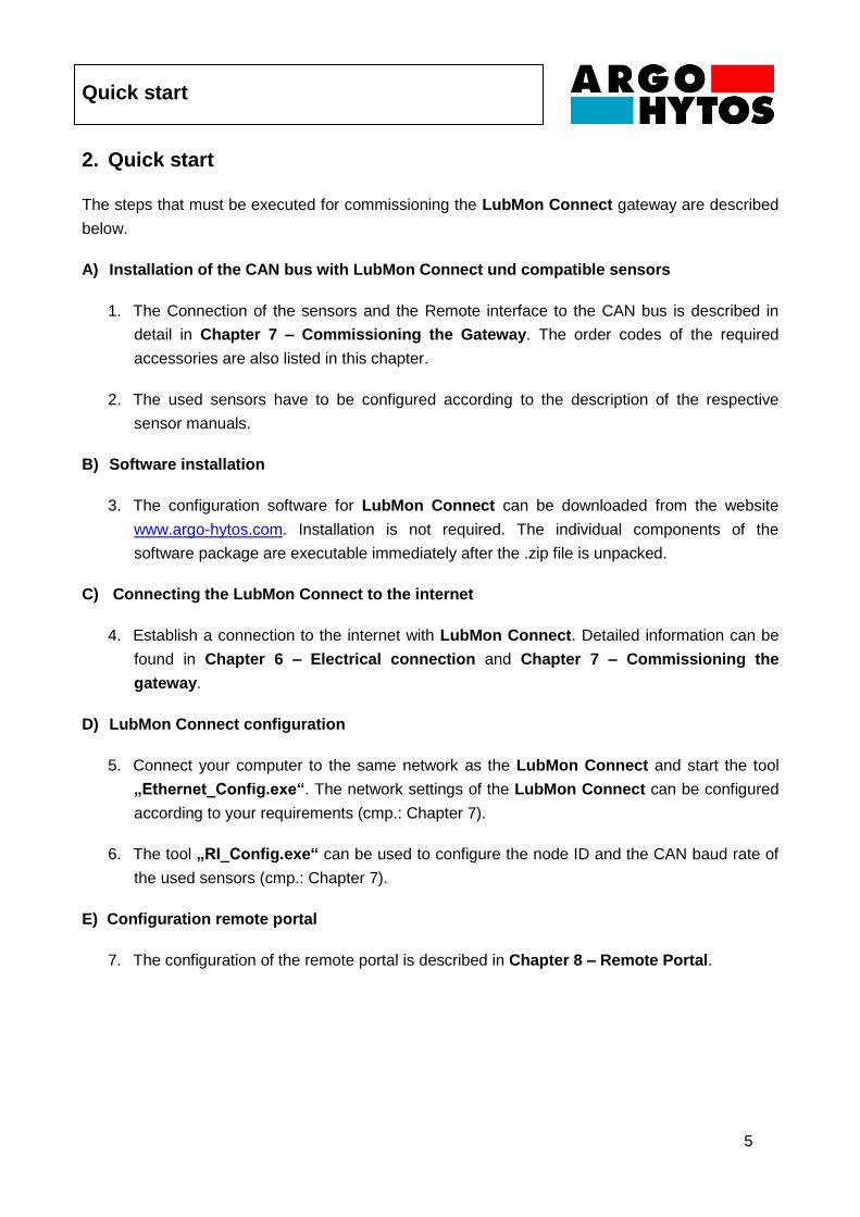
2. Quick start
The steps that must be executed for commissioning the LubMon Connect gateway are described
below.
A) Installation of the CAN bus with LubMon Connect und compatible sensors
1. The Connection of the sensors and the Remote interface to the CAN bus is described in
detail in Chapter 7 – Commissioning the Gateway. The order codes of the required
accessories are also listed in this chapter.
2. The used sensors have to be configured according to the description of the respective
sensor manuals.
B) Software installation
3. The configuration software for LubMon Connect can be downloaded from the website
www.argo-hytos.com. Installation is not required. The individual components of the
software package are executable immediately after the .zip file is unpacked.
C) Connecting the LubMon Connect to the internet
4. Establish a connection to the internet with LubMon Connect. Detailed information can be
found in Chapter 6 – Electrical connection and Chapter 7 – Commissioning the
gateway.
D) LubMon Connect configuration
5. Connect your computer to the same network as the LubMon Connect and start the tool
„Ethernet_Config.exe“. The network settings of the LubMon Connect can be configured
according to your requirements (cmp.: Chapter 7).
6. The tool „RI_Config.exe“ can be used to configure the node ID and the CAN baud rate of
the used sensors (cmp.: Chapter 7).
E) Configuration remote portal
7. The configuration of the remote portal is described in Chapter 8 – Remote Portal.

Performance features
6
3. Performance features
3.1. General
The gateway LubMon Connect is a remote gateway for the connection of ARGO-HYTOS sensors
via a CANopen interface. The data of the connected sensors is automatically transmitted to a web
database, and can be displayed and exported using a web page.
Figure 3.1: LubMon Connect
Using the CAN bus and the CANopen protocol provides a simple, robust way to integrate the
sensors into existing systems and to guarantee secure communication.
For communication with the Internet, the gateway provides an integrated Ethernet interface and an
integrated GSM module. Communication can either take place via the local network, or, in the case
of mobile or remote systems, using the highly developed global GSM network.
3.2. Data loggers
LubMon Connect Communicates with a server on the Internet that is able to store all incoming
data at programmable time intervals. The data can either be visualised online in graph form or
exported for subsequent analyses. A data storage capacity of 100,000 records is available for each
LubMon Connect. Once the memory has been exhausted, the oldest records are deleted
automatically.
Technical data
7
4. Technical data
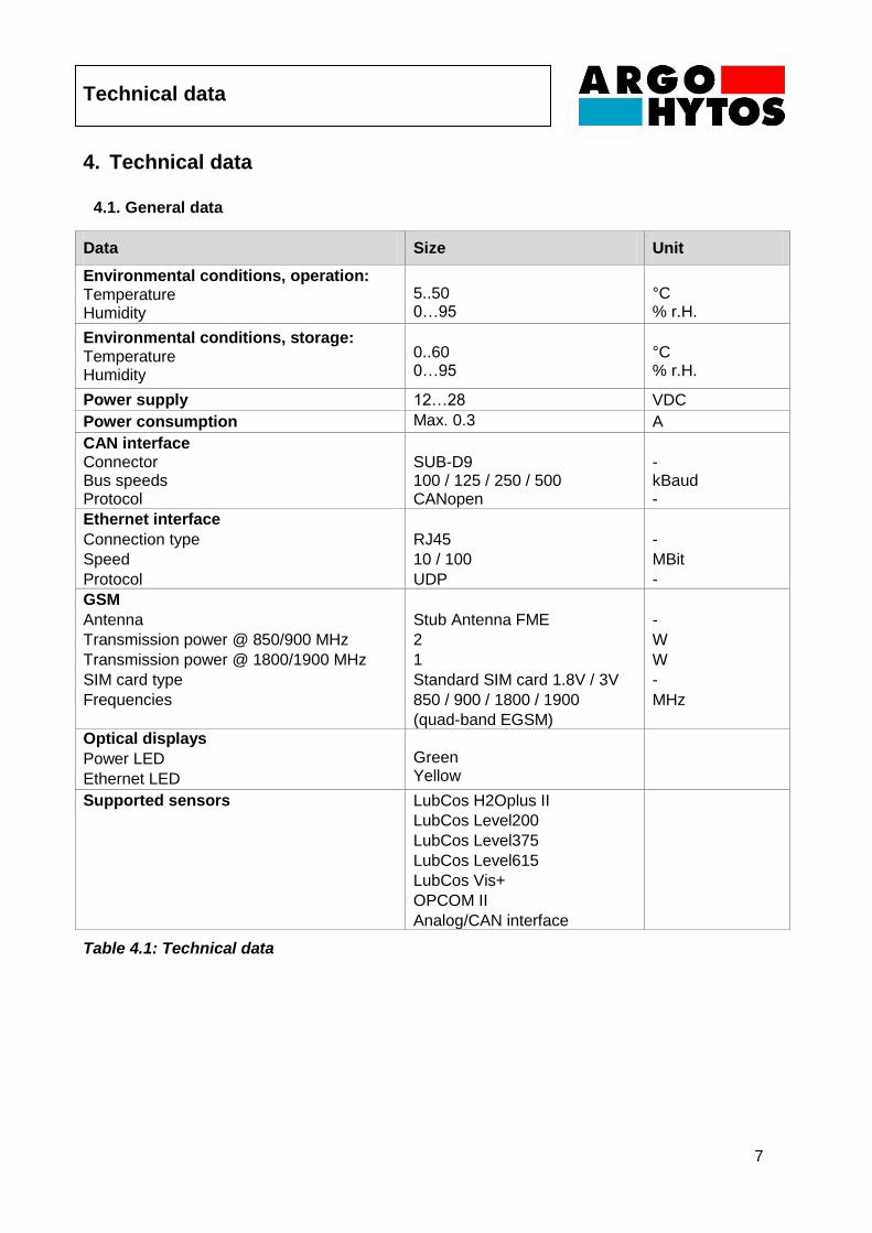
4.1. General data
Data Size Unit
Environmental conditions, operation: Temperature Humidity
5..50 0…95
°C % r.H.
Environmental conditions, storage: Temperature Humidity
0..60 0…95
°C % r.H.
Power supply 12…28 VDC
Power consumption Max. 0.3 A
CAN interface Connector Bus speeds Protocol
SUB-D9 100 / 125 / 250 / 500 CANopen
- kBaud -
Ethernet interface
Connection type
Speed
Protocol
RJ45
10 / 100
UDP
-
MBit
-
GSM
Antenna
Transmission power @ 850/900 MHz
Transmission power @ 1800/1900 MHz
SIM card type
Frequencies
Stub Antenna FME
2
1
Standard SIM card 1.8V / 3V
850 / 900 / 1800 / 1900
(quad-band EGSM)
-
W
W
-
MHz
Optical displays
Power LED
Ethernet LED
Green Yellow
Supported sensors LubCos H2Oplus II
LubCos Level200
LubCos Level375
LubCos Level615
LubCos Vis+
OPCOM II
Analog/CAN interface
Table 4.1: Technical data
Technical data
8
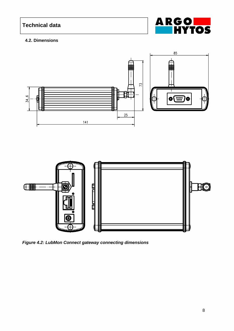
4.2. Dimensions
Figure 4.2: LubMon Connect gateway connecting dimensions
Installation
9
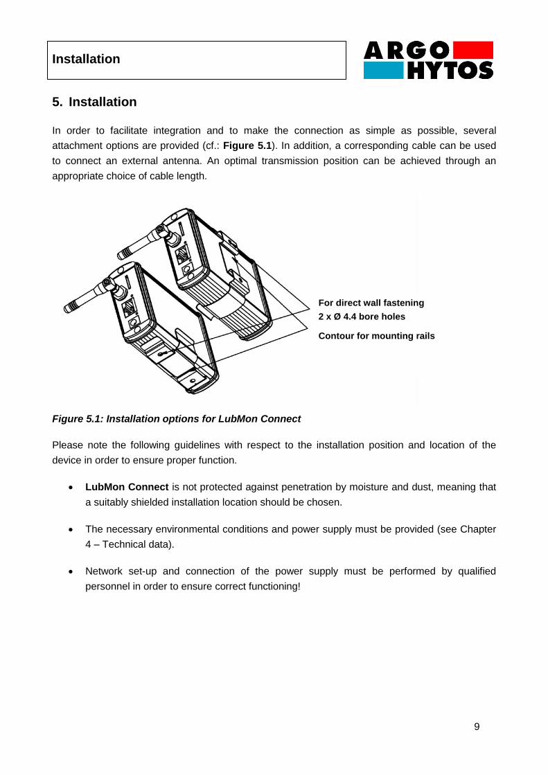
5. Installation
In order to facilitate integration and to make the connection as simple as possible, several
attachment options are provided (cf.: Figure 5.1). In addition, a corresponding cable can be used
to connect an external antenna. An optimal transmission position can be achieved through an
appropriate choice of cable length.
Figure 5.1: Installation options for LubMon Connect
Please note the following guidelines with respect to the installation position and location of the
device in order to ensure proper function.
LubMon Connect is not protected against penetration by moisture and dust, meaning that
a suitably shielded installation location should be chosen.
The necessary environmental conditions and power supply must be provided (see Chapter
4 – Technical data).
Network set-up and connection of the power supply must be performed by qualified
personnel in order to ensure correct functioning!
For direct wall fastening
2 x Ø 4.4 bore holes
Contour for mounting rails
Electrical connection
10
6. Electrical connection
6.1. General, plus safety notices
The electrical installation may only be performed by qualified professionals
(trained electricians) with the power off and in accordance with the applicable
standards and guidelines. The manufacturer will accept no responsibility in the
event of improper installation.
Comply with national and international guidelines for setting up electrical equipment. (Power supply
in accordance with EN50178, SELV, PELV, VDE0100-410/A1).
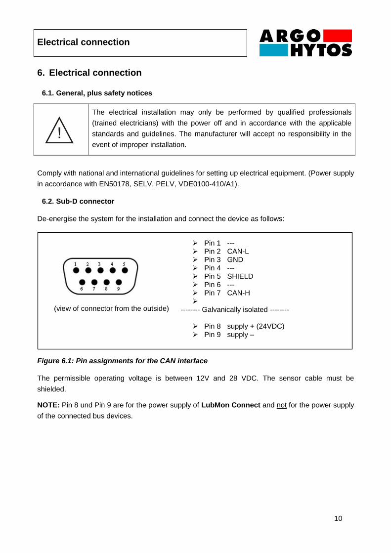
6.2. Sub-D connector
De-energise the system for the installation and connect the device as follows:
Figure 6.1: Pin assignments for the CAN interface
The permissible operating voltage is between 12V and 28 VDC. The sensor cable must be
shielded.
NOTE: Pin 8 und Pin 9 are for the power supply of LubMon Connect and not for the power supply
of the connected bus devices.
Pin 1 --- Pin 2 CAN-L Pin 3 GND Pin 4 --- Pin 5 SHIELD Pin 6 --- Pin 7 CAN-H
-------- Galvanically isolated --------
Pin 8 supply + (24VDC) Pin 9 supply –
(view of connector from the outside)

Electrical connection
11
6.3. Power supply via jack plug
If not powered via CAN bus (Sub-D connector), a separate power supply (order code SCSO 100-
5080) has to be connected to the jack plug (a) of the LubMon Connect.
Figure 6.2: Connectors of LubMon Connect
6.4. Ethernet connection
With a conventional patch cable connected to the Ethernet port (b), the LubMon Connect can be
integrated in the company network
6.5. SIM card slot
To establish a connection via GSM with the LubMon Connect, a conventional SIM card can be
inserted in the SIM card slot (c).
a b
c
Commissioning the gateway
12
7. Commissioning the gateway
Verify that the device has been correctly installed and is securely connected to mains. The
stipulations specified in Chapter 4.1, Chapter 5 and Chapter 6 must be satisfied for proper gateway
functionality.
Gateway commissioning using the Ethernet interface and GMS connection is described below.
7.1. Data transmission
Depending on the infrastructure available, the gateway can be connected to the Internet either
using a corporate network (Ethernet) or wireless network (GSM). Generally speaking, no additional
costs are incurred when connecting via Ethernet, since the transferred data volumes are relatively
small and will hardly make a difference in terms of the overall flow of data across a corporate
network. However, it may be necessary to adapt the corporate network or the firewall and/or router.
When connecting via GSM, a mobile phone card (what is referred to as a SIM card) and
corresponding service contract is required to enable data transmission. Moreover, in this case the
gateway needs to be installed so as to enable a wireless connection to the GSM network.
7.2. Connecting sensors to the gateway
The gateway communicates with the sensors of the CAN bus using the CANopen protocol. When
connecting the sensor to the CAN bus, the cable specified for this purpose must be used in order
to ensure reliable communication over the bus.
For details regarding how to configure the CANopen interface of the sensors used, please see the
respective product manual. Make sure that the sensor's CANopen communication is activated and
that different node IDs and identical baud rates have been configured. No additional expertise
regarding CAN/CANopen is needed to configure and operate the sensors using LubMon Connect.
Commissioning the gateway
13
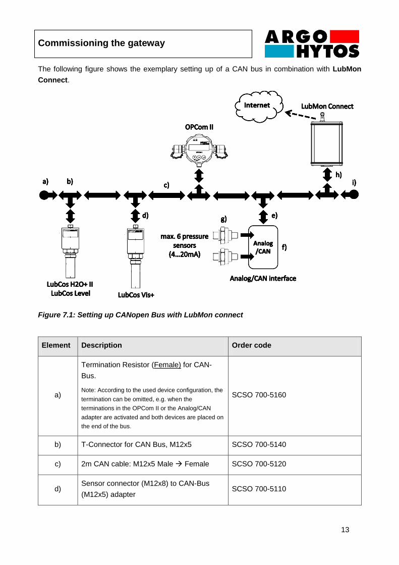
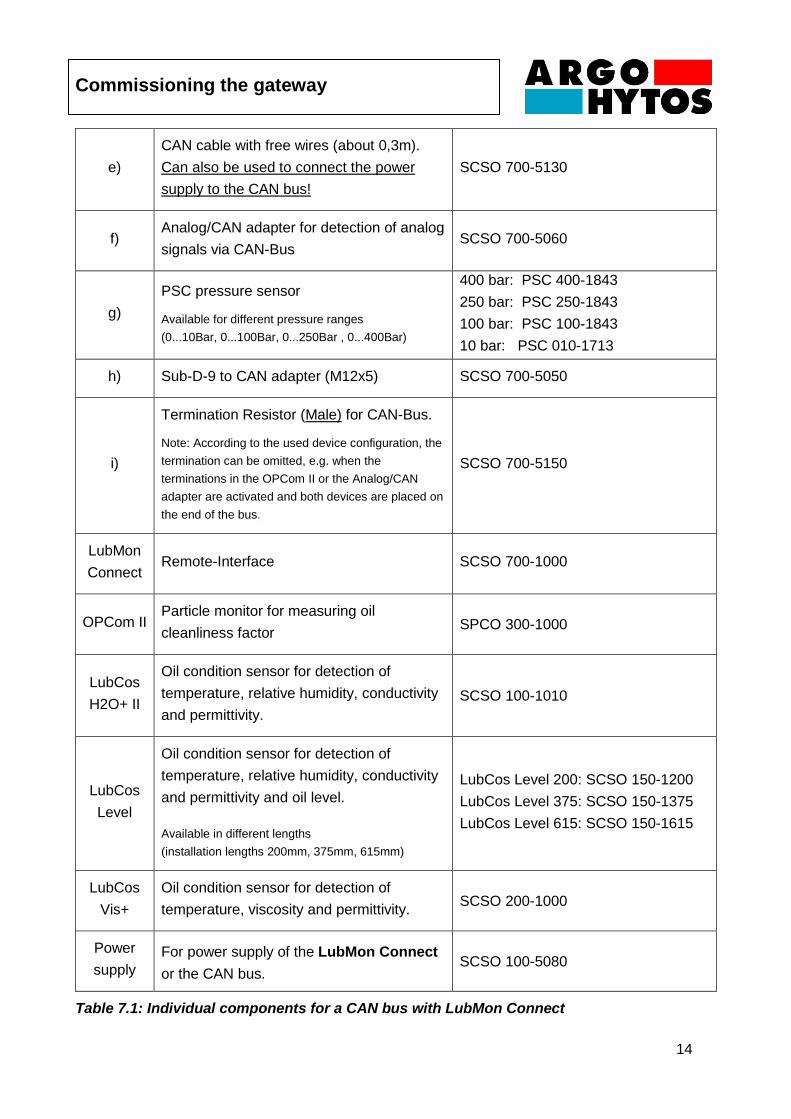
The following figure shows the exemplary setting up of a CAN bus in combination with LubMon
Connect.
Figure 7.1: Setting up CANopen Bus with LubMon connect
Element Description Order code
a)
Termination Resistor (Female) for CAN-
Bus.
Note: According to the used device configuration, the
termination can be omitted, e.g. when the
terminations in the OPCom II or the Analog/CAN
adapter are activated and both devices are placed on
the end of the bus.
SCSO 700-5160
b) T-Connector for CAN Bus, M12x5 SCSO 700-5140
c) 2m CAN cable: M12x5 Male Female SCSO 700-5120
d) Sensor connector (M12x8) to CAN-Bus
(M12x5) adapter SCSO 700-5110
Commissioning the gateway
14
e)
CAN cable with free wires (about 0,3m).
Can also be used to connect the power
supply to the CAN bus!
SCSO 700-5130
f) Analog/CAN adapter for detection of analog
signals via CAN-Bus SCSO 700-5060
g)
PSC pressure sensor
Available for different pressure ranges
(0...10Bar, 0...100Bar, 0...250Bar , 0...400Bar)
400 bar: PSC 400-1843
250 bar: PSC 250-1843
100 bar: PSC 100-1843
10 bar: PSC 010-1713
h) Sub-D-9 to CAN adapter (M12x5) SCSO 700-5050
i)
Termination Resistor (Male) for CAN-Bus.
Note: According to the used device configuration, the
termination can be omitted, e.g. when the
terminations in the OPCom II or the Analog/CAN
adapter are activated and both devices are placed on
the end of the bus.
SCSO 700-5150
LubMon
Connect Remote-Interface SCSO 700-1000
OPCom II Particle monitor for measuring oil
cleanliness factor SPCO 300-1000
LubCos
H2O+ II
Oil condition sensor for detection of
temperature, relative humidity, conductivity
and permittivity.
SCSO 100-1010
LubCos
Level
Oil condition sensor for detection of
temperature, relative humidity, conductivity
and permittivity and oil level.
Available in different lengths
(installation lengths 200mm, 375mm, 615mm)
LubCos Level 200: SCSO 150-1200
LubCos Level 375: SCSO 150-1375
LubCos Level 615: SCSO 150-1615
LubCos
Vis+
Oil condition sensor for detection of
temperature, viscosity and permittivity. SCSO 200-1000
Power
supply
For power supply of the LubMon Connect
or the CAN bus. SCSO 100-5080
Table 7.1: Individual components for a CAN bus with LubMon Connect
Commissioning the gateway
15
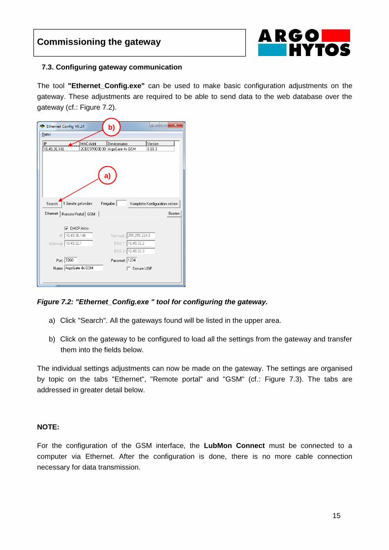
7.3. Configuring gateway communication
The tool "Ethernet_Config.exe" can be used to make basic configuration adjustments on the
gateway. These adjustments are required to be able to send data to the web database over the
gateway (cf.: Figure 7.2).
Figure 7.2: "Ethernet_Config.exe " tool for configuring the gateway.
a) Click "Search". All the gateways found will be listed in the upper area.
b) Click on the gateway to be configured to load all the settings from the gateway and transfer
them into the fields below.
The individual settings adjustments can now be made on the gateway. The settings are organised
by topic on the tabs "Ethernet", "Remote portal" and "GSM" (cf.: Figure 7.3). The tabs are
addressed in greater detail below.
NOTE:
For the configuration of the GSM interface, the LubMon Connect must be connected to a
computer via Ethernet. After the configuration is done, there is no more cable connection
necessary for data transmission.
b)
a)
Commissioning the gateway
16
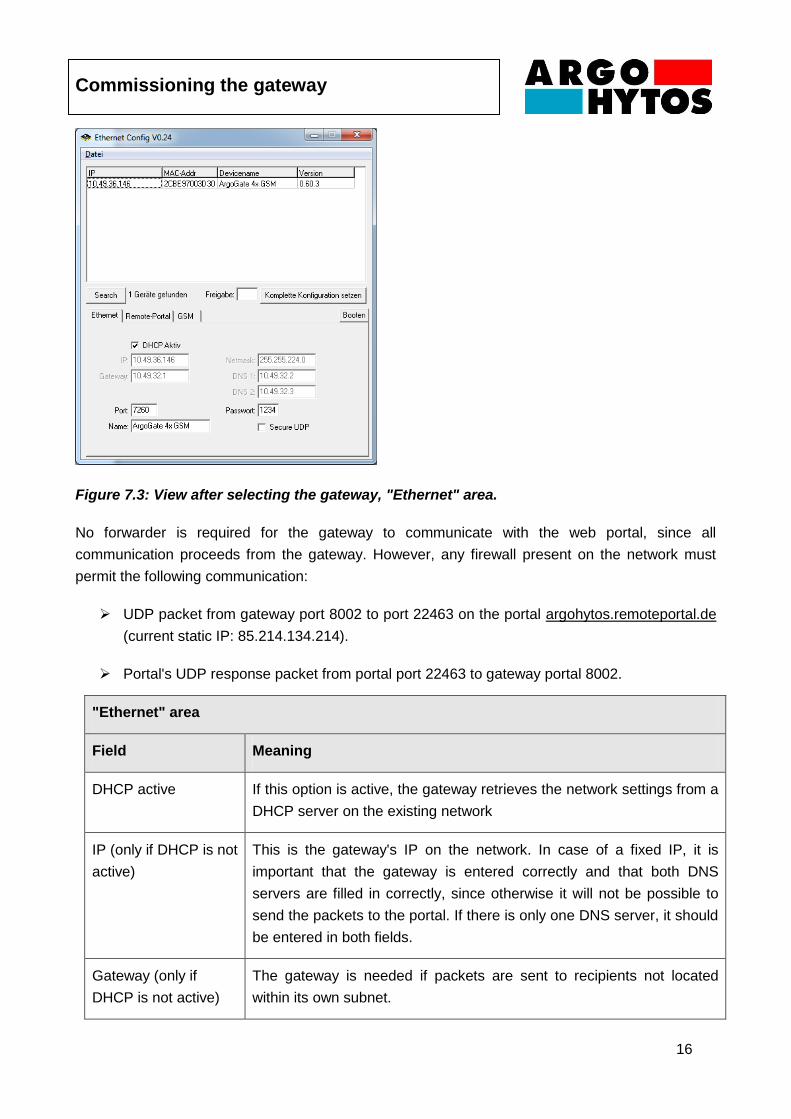
Figure 7.3: View after selecting the gateway, "Ethernet" area.
No forwarder is required for the gateway to communicate with the web portal, since all
communication proceeds from the gateway. However, any firewall present on the network must
permit the following communication:
UDP packet from gateway port 8002 to port 22463 on the portal argohytos.remoteportal.de
(current static IP: 85.214.134.214).
Portal's UDP response packet from portal port 22463 to gateway portal 8002.
"Ethernet" area
Field Meaning
DHCP active If this option is active, the gateway retrieves the network settings from a
DHCP server on the existing network
IP (only if DHCP is not
active)
This is the gateway's IP on the network. In case of a fixed IP, it is
important that the gateway is entered correctly and that both DNS
servers are filled in correctly, since otherwise it will not be possible to
send the packets to the portal. If there is only one DNS server, it should
be entered in both fields.
Gateway (only if
DHCP is not active)
The gateway is needed if packets are sent to recipients not located
within its own subnet.
Commissioning the gateway
17
Netmask (only if
DHCP is not active)
The subnetmask is needed in order to find which part of the IPs has to
be identical in order to belong to the corresponding subnet.
DNS1/DNS2 (only if
DHCP is not active)
The DNS server(s) serve(s) to resolve Internet addresses. If there is
only one DNS server, it should be entered in both fields.
Port This port is used for application-dependent gateway configuration. This
setting can normally be retained.
Password The password is needed in order to be able to access the gateway via
Ethernet. This is meant to prevent unauthorised access to the gateway
over the Internet.
Secure UDP If this option is active, the correct password needs to be entered under
"Release" for each configuration setting (also using this tool) in order to
be able to access the configuration.
Table 7.2: Settings for the "Ethernet" area
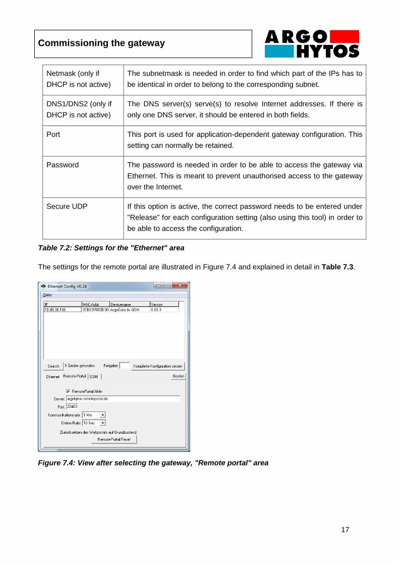
The settings for the remote portal are illustrated in Figure 7.4 and explained in detail in Table 7.3.
Figure 7.4: View after selecting the gateway, "Remote portal" area
Commissioning the gateway
18
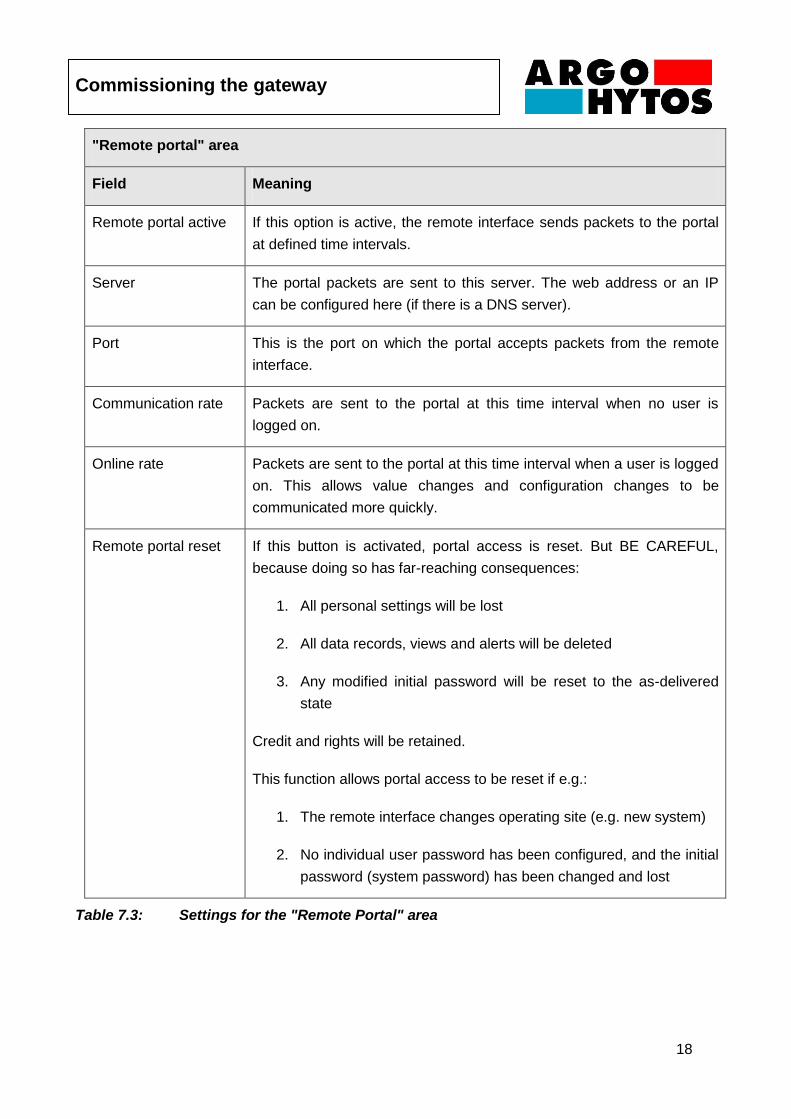
"Remote portal" area
Field Meaning
Remote portal active If this option is active, the remote interface sends packets to the portal
at defined time intervals.
Server The portal packets are sent to this server. The web address or an IP
can be configured here (if there is a DNS server).
Port This is the port on which the portal accepts packets from the remote
interface.
Communication rate Packets are sent to the portal at this time interval when no user is
logged on.
Online rate Packets are sent to the portal at this time interval when a user is logged
on. This allows value changes and configuration changes to be
communicated more quickly.
Remote portal reset If this button is activated, portal access is reset. But BE CAREFUL,
because doing so has far-reaching consequences:
1. All personal settings will be lost
2. All data records, views and alerts will be deleted
3. Any modified initial password will be reset to the as-delivered
state
Credit and rights will be retained.
This function allows portal access to be reset if e.g.:
1. The remote interface changes operating site (e.g. new system)
2. No individual user password has been configured, and the initial
password (system password) has been changed and lost
Table 7.3: Settings for the "Remote Portal" area
Commissioning the gateway
19
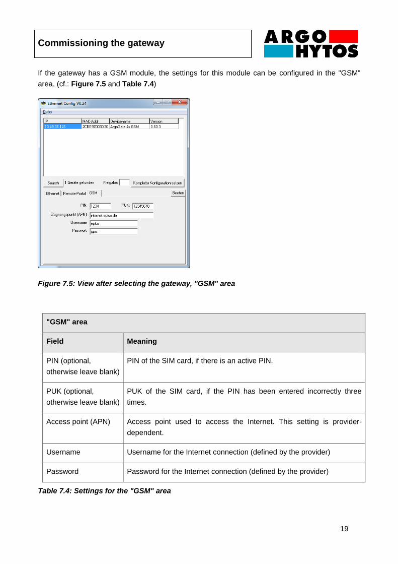
If the gateway has a GSM module, the settings for this module can be configured in the "GSM"
area. (cf.: Figure 7.5 and Table 7.4)
Figure 7.5: View after selecting the gateway, "GSM" area
"GSM" area
Field Meaning
PIN (optional,
otherwise leave blank)
PIN of the SIM card, if there is an active PIN.
PUK (optional,
otherwise leave blank)
PUK of the SIM card, if the PIN has been entered incorrectly three
times.
Access point (APN) Access point used to access the Internet. This setting is provider-
dependent.
Username Username for the Internet connection (defined by the provider)
Password Password for the Internet connection (defined by the provider)
Table 7.4: Settings for the "GSM" area
Commissioning the gateway
20
The modified configuration can be imported to the gateway using the "Set complete configuration"
button. If "Secure UDP" is active, the password for it also needs to be entered in "Release". After
successful configuration and running "Search" again, it is recommended that the configuration in
the gateway is reviewed once more.
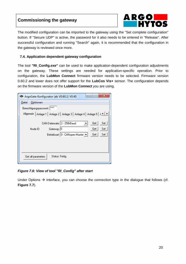
7.4. Application dependent gateway configuration
The tool "RI_Config.exe" can be used to make application-dependent configuration adjustments
on the gateway. These settings are needed for application-specific operation. Prior to
configuration, the LubMon Connect firmware version needs to be selected. Firmware version
0.60.2 and lower does not offer support for the LubCos Vis+ sensor. The configuration depends
on the firmware version of the LubMon Connect you are using.
Figure 7.6: View of tool "RI_Config" after start
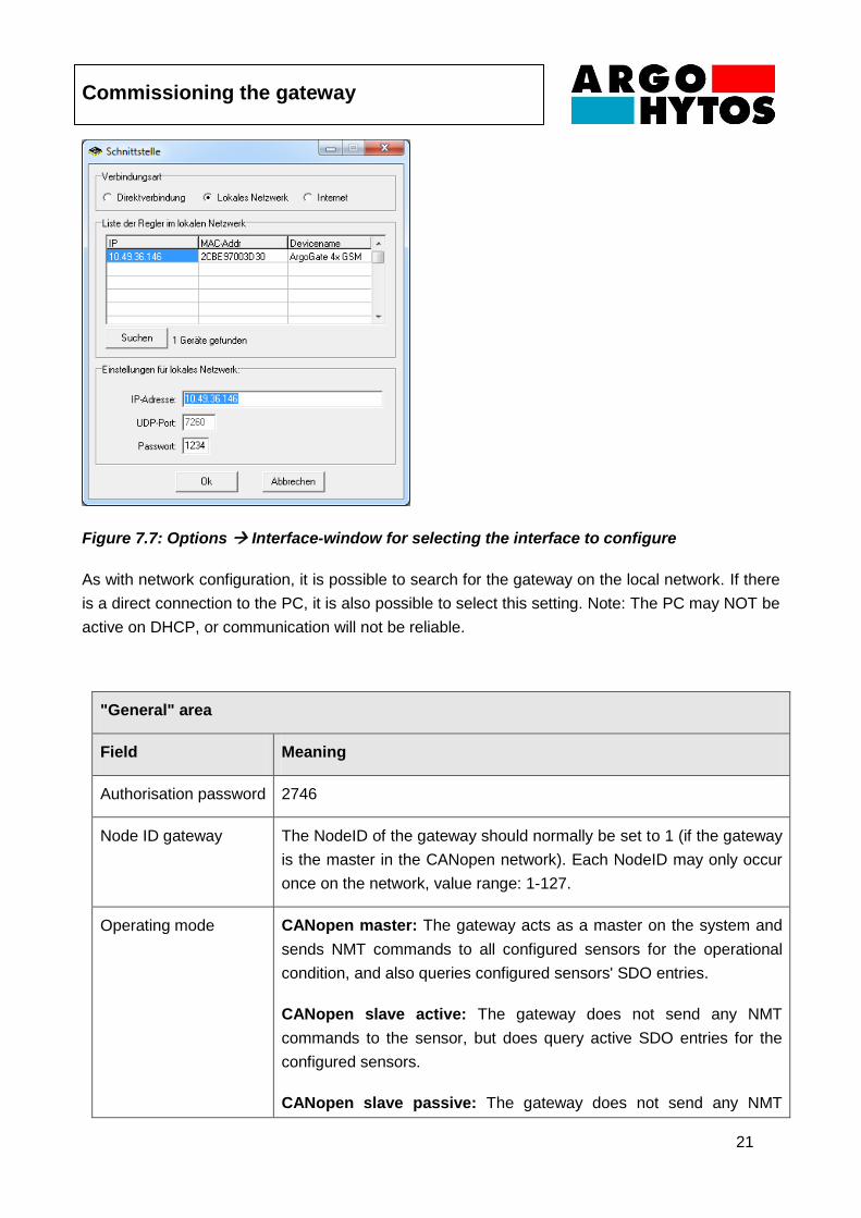
Under Options Interface, you can choose the connection type in the dialogue that follows (cf.
Figure 7.7).
Commissioning the gateway
21
Figure 7.7: Options Interface-window for selecting the interface to configure
As with network configuration, it is possible to search for the gateway on the local network. If there
is a direct connection to the PC, it is also possible to select this setting. Note: The PC may NOT be
active on DHCP, or communication will not be reliable.
"General" area
Field Meaning
Authorisation password 2746
Node ID gateway The NodeID of the gateway should normally be set to 1 (if the gateway
is the master in the CANopen network). Each NodeID may only occur
once on the network, value range: 1-127.
Operating mode CANopen master: The gateway acts as a master on the system and
sends NMT commands to all configured sensors for the operational
condition, and also queries configured sensors' SDO entries.
CANopen slave active: The gateway does not send any NMT
commands to the sensor, but does query active SDO entries for the
configured sensors.
CANopen slave passive: The gateway does not send any NMT

Commissioning the gateway
22
commands to the sensors, and does not actively query any SDO
entries for the configured sensors. However, it does scan these when
somebody else accesses these entries.
100% passive: The gateway does not send any NMT commands
to the sensors, and does not actively query any SDO entries for the
configured sensors. However, it does scan these when somebody else
accesses these entries.
Table 7.5: Settings for the "General" area
With the slides “Anlage 1” to “Anlage 8” the identification code (“Kennung”) and the node IDs of the
connected sensors can be transmitted to the LubMon Connect.
NOTE: Every machine supports only one LubCos H2O+ II or one LubCos Level, one LubCos Vis+,
one OPCom II and one Analog/CAN adapter.
Figure 7.8: View for the selected tab "System 1"
Commissioning the gateway
23
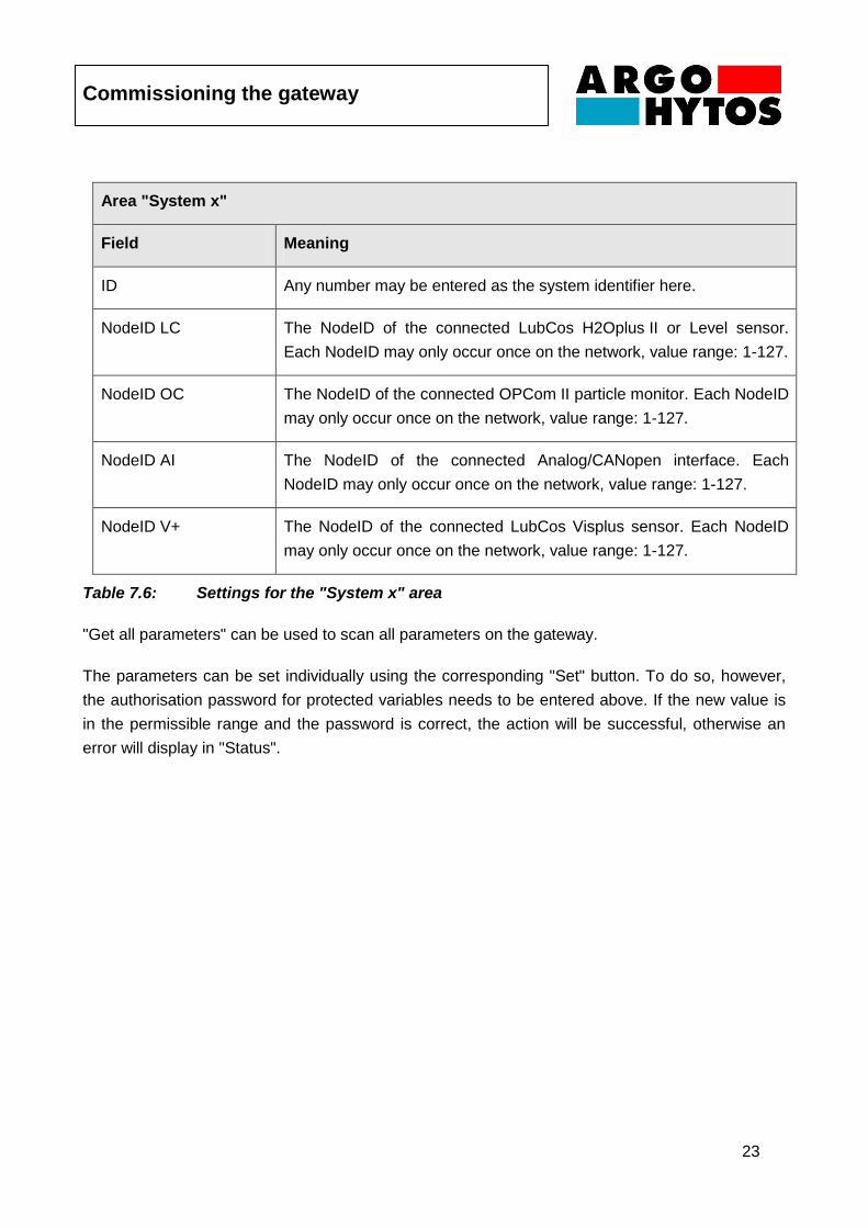
Area "System x"
Field Meaning
ID Any number may be entered as the system identifier here.
NodeID LC The NodeID of the connected LubCos H2Oplus II or Level sensor.
Each NodeID may only occur once on the network, value range: 1-127.
NodeID OC The NodeID of the connected OPCom II particle monitor. Each NodeID
may only occur once on the network, value range: 1-127.
NodeID AI The NodeID of the connected Analog/CANopen interface. Each
NodeID may only occur once on the network, value range: 1-127.
NodeID V+ The NodeID of the connected LubCos Visplus sensor. Each NodeID
may only occur once on the network, value range: 1-127.
Table 7.6: Settings for the "System x" area
"Get all parameters" can be used to scan all parameters on the gateway.
The parameters can be set individually using the corresponding "Set" button. To do so, however,
the authorisation password for protected variables needs to be entered above. If the new value is
in the permissible range and the password is correct, the action will be successful, otherwise an
error will display in "Status".
Commissioning the gateway
24
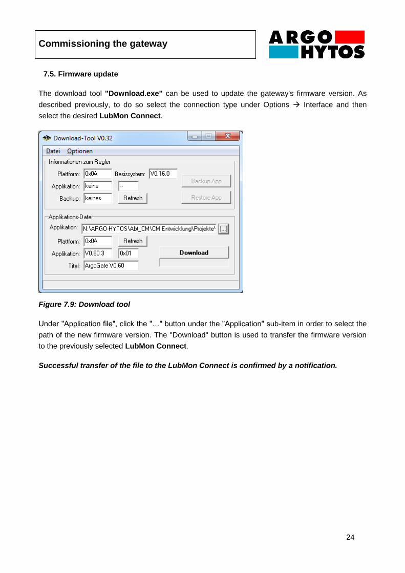
7.5. Firmware update
The download tool "Download.exe" can be used to update the gateway's firmware version. As
described previously, to do so select the connection type under Options Interface and then
select the desired LubMon Connect.
Figure 7.9: Download tool
Under "Application file", click the "…" button under the "Application" sub-item in order to select the
path of the new firmware version. The "Download" button is used to transfer the firmware version
to the previously selected LubMon Connect.
Successful transfer of the file to the LubMon Connect is confirmed by a notification.
Remote portal
25
8. Remote portal
8.1. Logon
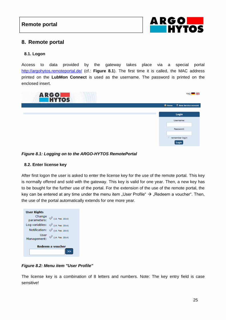
Access to data provided by the gateway takes place via a special portal
http://argohytos.remoteportal.de/ (cf.: Figure 8.1). The first time it is called, the MAC address
printed on the LubMon Connect is used as the username. The password is printed on the
enclosed insert.
Figure 8.1: Logging on to the ARGO-HYTOS RemotePortal
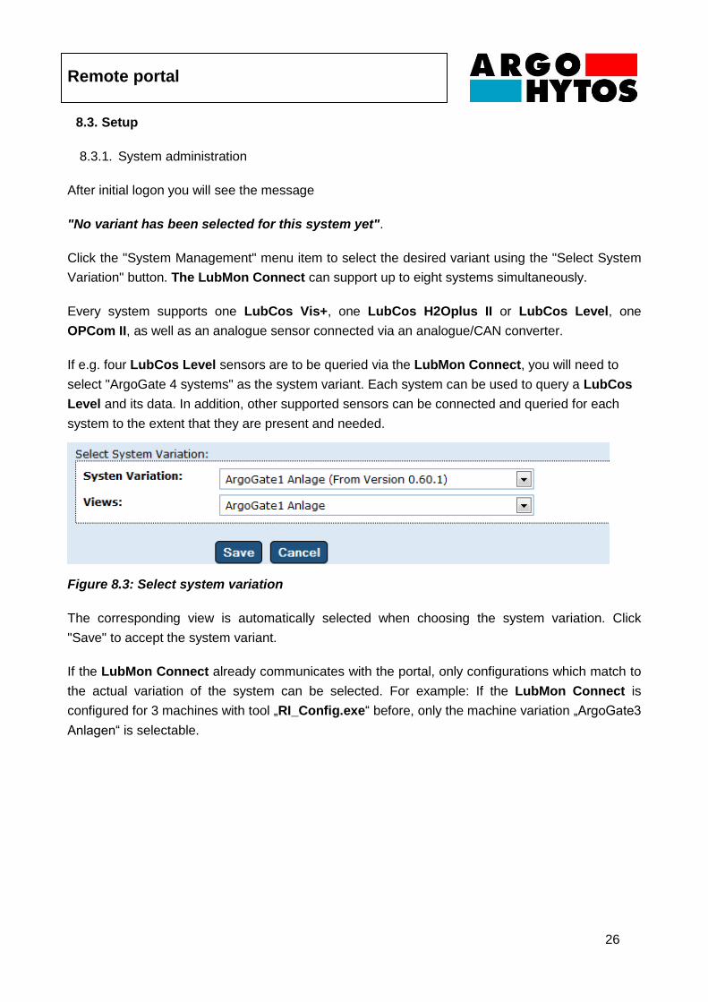
8.2. Enter license key
After first logon the user is asked to enter the license key for the use of the remote portal. This key
is normally offered and sold with the gateway. This key is valid for one year. Then, a new key has
to be bought for the further use of the portal. For the extension of the use of the remote portal, the
key can be entered at any time under the menu item „User Profile“ „Redeem a voucher“. Then,
the use of the portal automatically extends for one more year.
Figure 8.2: Menu item "User Profile"
The license key is a combination of 8 letters and numbers. Note: The key entry field is case
sensitive!
Remote portal
26
8.3. Setup
8.3.1. System administration
After initial logon you will see the message
"No variant has been selected for this system yet".
Click the "System Management" menu item to select the desired variant using the "Select System
Variation" button. The LubMon Connect can support up to eight systems simultaneously.
Every system supports one LubCos Vis+, one LubCos H2Oplus II or LubCos Level, one
OPCom II, as well as an analogue sensor connected via an analogue/CAN converter.
If e.g. four LubCos Level sensors are to be queried via the LubMon Connect, you will need to
select "ArgoGate 4 systems" as the system variant. Each system can be used to query a LubCos
Level and its data. In addition, other supported sensors can be connected and queried for each
system to the extent that they are present and needed.
Figure 8.3: Select system variation
The corresponding view is automatically selected when choosing the system variation. Click
"Save" to accept the system variant.
If the LubMon Connect already communicates with the portal, only configurations which match to
the actual variation of the system can be selected. For example: If the LubMon Connect is
configured for 3 machines with tool „RI_Config.exe“ before, only the machine variation „ArgoGate3
Anlagen“ is selectable.
Remote portal
27
8.3.2. Systems view
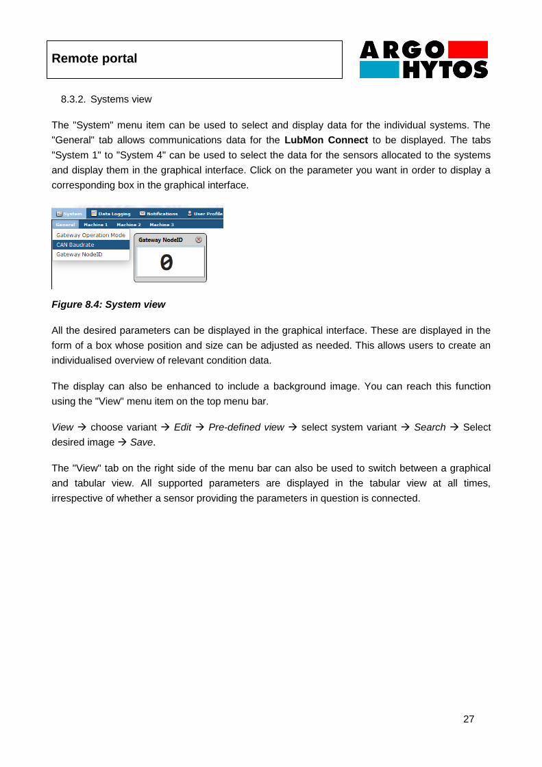
The "System" menu item can be used to select and display data for the individual systems. The
"General" tab allows communications data for the LubMon Connect to be displayed. The tabs
"System 1" to "System 4" can be used to select the data for the sensors allocated to the systems
and display them in the graphical interface. Click on the parameter you want in order to display a
corresponding box in the graphical interface.
Figure 8.4: System view
All the desired parameters can be displayed in the graphical interface. These are displayed in the
form of a box whose position and size can be adjusted as needed. This allows users to create an
individualised overview of relevant condition data.
The display can also be enhanced to include a background image. You can reach this function
using the "View" menu item on the top menu bar.
View choose variant Edit Pre-defined view select system variant Search Select
desired image Save.
The "View" tab on the right side of the menu bar can also be used to switch between a graphical
and tabular view. All supported parameters are displayed in the tabular view at all times,
irrespective of whether a sensor providing the parameters in question is connected.
Remote portal
28
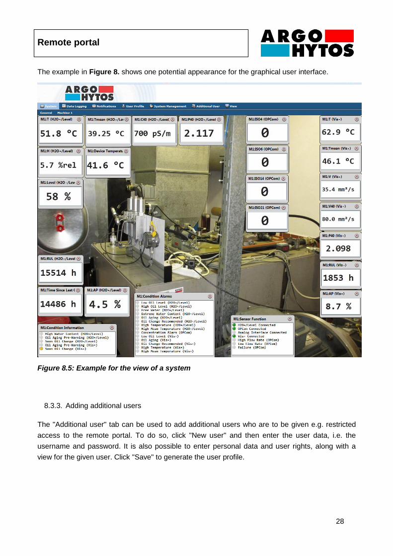
The example in Figure 8. shows one potential appearance for the graphical user interface.
Figure 8.5: Example for the view of a system
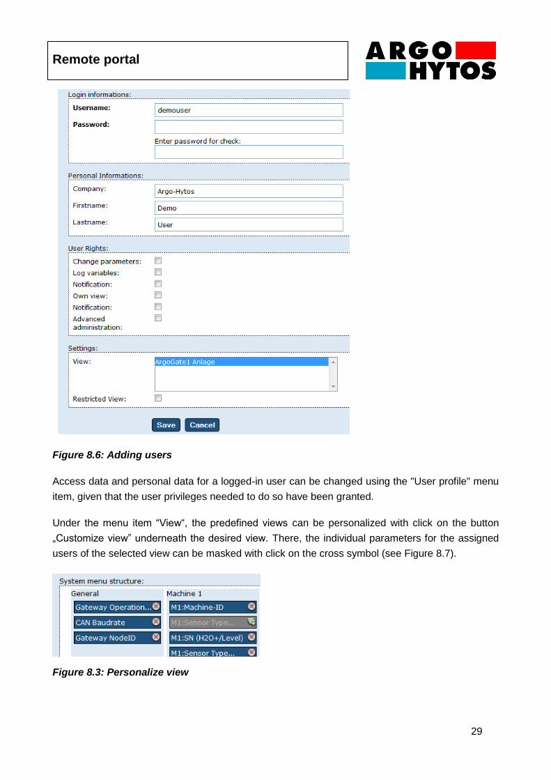
8.3.3. Adding additional users
The "Additional user" tab can be used to add additional users who are to be given e.g. restricted
access to the remote portal. To do so, click "New user" and then enter the user data, i.e. the
username and password. It is also possible to enter personal data and user rights, along with a
view for the given user. Click "Save" to generate the user profile.
Remote portal
29
Figure 8.6: Adding users
Access data and personal data for a logged-in user can be changed using the "User profile" menu
item, given that the user privileges needed to do so have been granted.
Under the menu item “View“, the predefined views can be personalized with click on the button
„Customize view” underneath the desired view. There, the individual parameters for the assigned
users of the selected view can be masked with click on the cross symbol (see Figure 8.7).
Figure 8.3: Personalize view
Remote portal
30
8.4. Data management
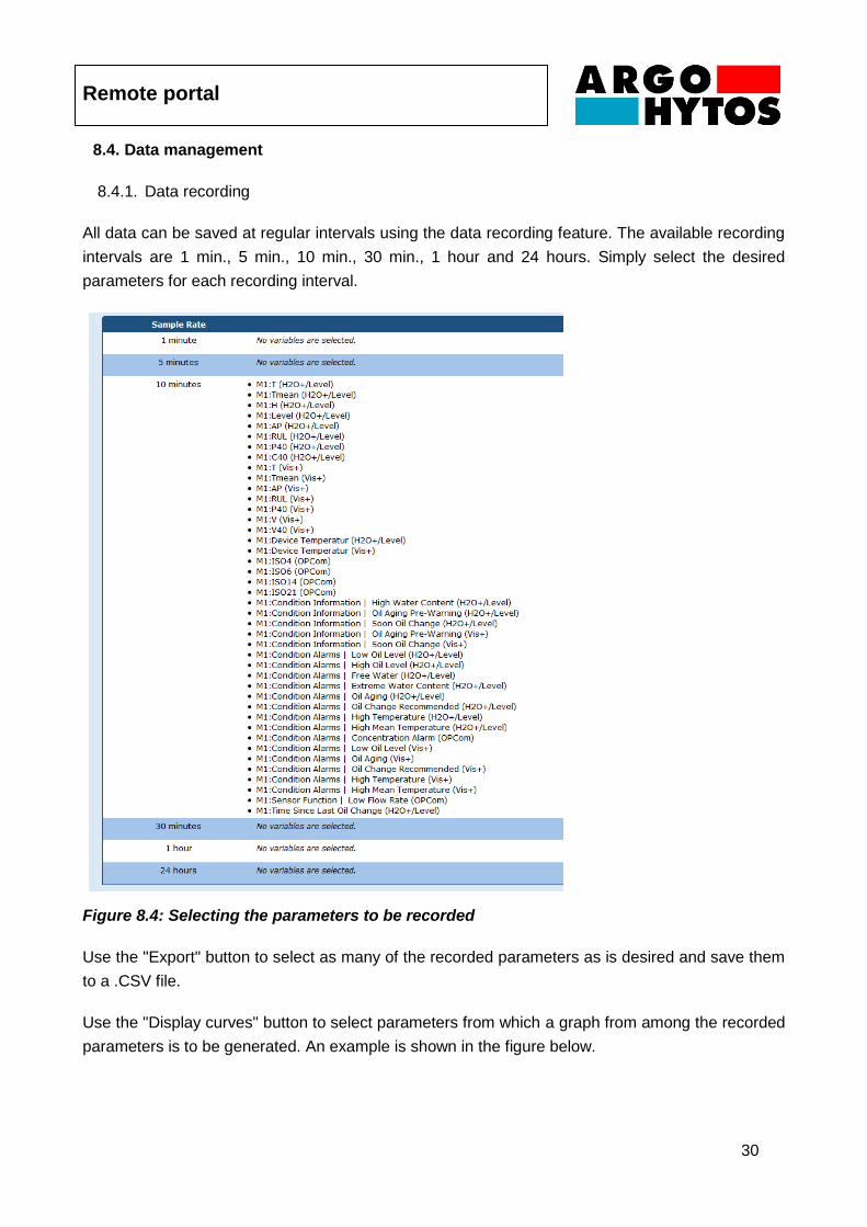
8.4.1. Data recording
All data can be saved at regular intervals using the data recording feature. The available recording
intervals are 1 min., 5 min., 10 min., 30 min., 1 hour and 24 hours. Simply select the desired
parameters for each recording interval.
Figure 8.4: Selecting the parameters to be recorded
Use the "Export" button to select as many of the recorded parameters as is desired and save them
to a .CSV file.
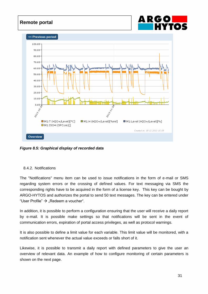
Use the "Display curves" button to select parameters from which a graph from among the recorded
parameters is to be generated. An example is shown in the figure below.
Remote portal
31
Figure 8.5: Graphical display of recorded data
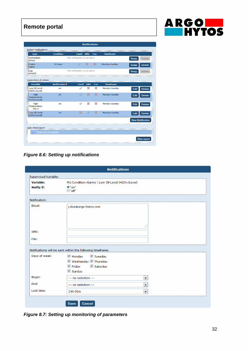
8.4.2. Notifications
The "Notifications" menu item can be used to issue notifications in the form of e-mail or SMS
regarding system errors or the crossing of defined values. For text messaging via SMS the
corresponding rights have to be acquired in the form of a license key. This key can be bought by
ARGO-HYTOS and authorizes the portal to send 50 text messages. The key can be entered under
“User Profile” „Redeem a voucher“.
In addition, it is possible to perform a configuration ensuring that the user will receive a daily report
by e-mail. It is possible make settings so that notifications will be sent in the event of
communication errors, expiration of portal access privileges, as well as protocol warnings.
It is also possible to define a limit value for each variable. This limit value will be monitored, with a
notification sent whenever the actual value exceeds or falls short of it.
Likewise, it is possible to transmit a daily report with defined parameters to give the user an
overview of relevant data. An example of how to configure monitoring of certain parameters is
shown on the next page.
Remote portal
32
Figure 8.6: Setting up notifications
Figure 8.7: Setting up monitoring of parameters
Parameter overview
33
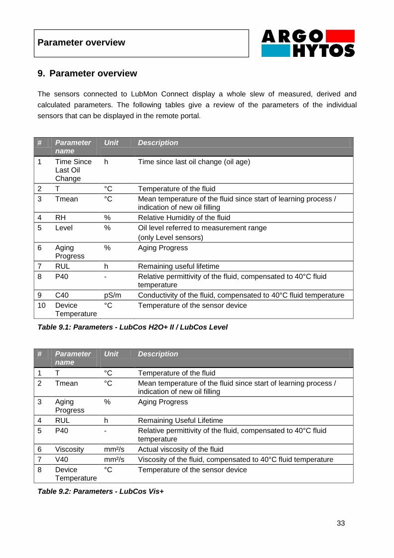
9. Parameter overview
The sensors connected to LubMon Connect display a whole slew of measured, derived and
calculated parameters. The following tables give a review of the parameters of the individual
sensors that can be displayed in the remote portal.
# Parameter name
Unit Description
1 Time Since Last Oil Change
h Time since last oil change (oil age)
2 T °C Temperature of the fluid
3 Tmean °C Mean temperature of the fluid since start of learning process / indication of new oil filling
4 RH % Relative Humidity of the fluid
5 Level % Oil level referred to measurement range
(only Level sensors)
6 Aging Progress
% Aging Progress
7 RUL h Remaining useful lifetime
8 P40 - Relative permittivity of the fluid, compensated to 40°C fluid temperature
9 C40 pS/m Conductivity of the fluid, compensated to 40°C fluid temperature
10 Device Temperature
°C Temperature of the sensor device
Table 9.1: Parameters - LubCos H2O+ II / LubCos Level
# Parameter name
Unit Description
1 T °C Temperature of the fluid
2 Tmean °C Mean temperature of the fluid since start of learning process / indication of new oil filling
3 Aging Progress
% Aging Progress
4 RUL h Remaining Useful Lifetime
5 P40 - Relative permittivity of the fluid, compensated to 40°C fluid temperature
6 Viscosity mm²/s Actual viscosity of the fluid
7 V40 mm²/s Viscosity of the fluid, compensated to 40°C fluid temperature
8 Device Temperature
°C Temperature of the sensor device
Table 9.2: Parameters - LubCos Vis+
Parameter overview
34
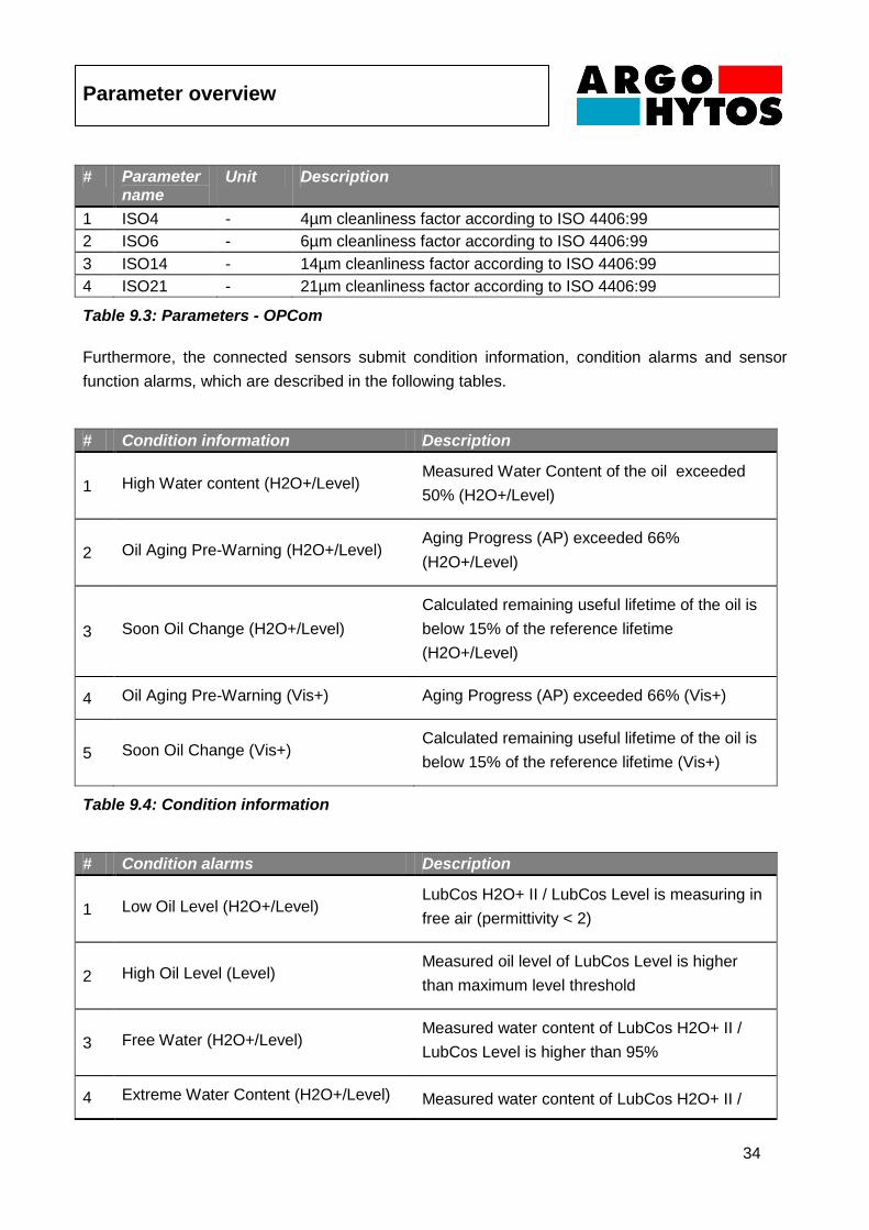
# Parameter name
Unit Description
1 ISO4 - 4µm cleanliness factor according to ISO 4406:99
2 ISO6 - 6µm cleanliness factor according to ISO 4406:99
3 ISO14 - 14µm cleanliness factor according to ISO 4406:99
4 ISO21 - 21µm cleanliness factor according to ISO 4406:99
Table 9.3: Parameters - OPCom
Furthermore, the connected sensors submit condition information, condition alarms and sensor
function alarms, which are described in the following tables.
# Condition information Description
1 High Water content (H2O+/Level) Measured Water Content of the oil exceeded
50% (H2O+/Level)
2 Oil Aging Pre-Warning (H2O+/Level) Aging Progress (AP) exceeded 66%
(H2O+/Level)
3 Soon Oil Change (H2O+/Level)
Calculated remaining useful lifetime of the oil is
below 15% of the reference lifetime
(H2O+/Level)
4 Oil Aging Pre-Warning (Vis+) Aging Progress (AP) exceeded 66% (Vis+)
5 Soon Oil Change (Vis+) Calculated remaining useful lifetime of the oil is
below 15% of the reference lifetime (Vis+)
Table 9.4: Condition information
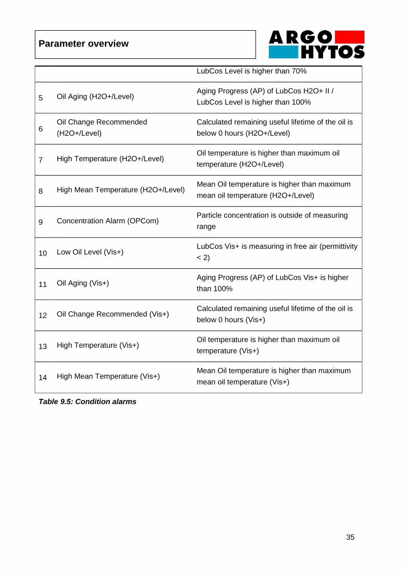
# Condition alarms Description
1 Low Oil Level (H2O+/Level) LubCos H2O+ II / LubCos Level is measuring in
free air (permittivity < 2)
2 High Oil Level (Level) Measured oil level of LubCos Level is higher
than maximum level threshold
3 Free Water (H2O+/Level) Measured water content of LubCos H2O+ II /
LubCos Level is higher than 95%
4 Extreme Water Content (H2O+/Level) Measured water content of LubCos H2O+ II /
Parameter overview
35
LubCos Level is higher than 70%
5 Oil Aging (H2O+/Level) Aging Progress (AP) of LubCos H2O+ II /
LubCos Level is higher than 100%
6 Oil Change Recommended
(H2O+/Level)
Calculated remaining useful lifetime of the oil is
below 0 hours (H2O+/Level)
7 High Temperature (H2O+/Level) Oil temperature is higher than maximum oil
temperature (H2O+/Level)
8 High Mean Temperature (H2O+/Level) Mean Oil temperature is higher than maximum
mean oil temperature (H2O+/Level)
9 Concentration Alarm (OPCom) Particle concentration is outside of measuring
range
10 Low Oil Level (Vis+) LubCos Vis+ is measuring in free air (permittivity
< 2)
11 Oil Aging (Vis+) Aging Progress (AP) of LubCos Vis+ is higher
than 100%
12 Oil Change Recommended (Vis+) Calculated remaining useful lifetime of the oil is
below 0 hours (Vis+)
13 High Temperature (Vis+) Oil temperature is higher than maximum oil
temperature (Vis+)
14 High Mean Temperature (Vis+) Mean Oil temperature is higher than maximum
mean oil temperature (Vis+)
Table 9.5: Condition alarms
Parameter overview
36
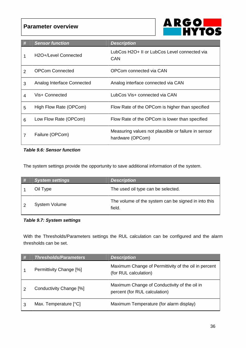
# Sensor function Description
1 H2O+/Level Connected LubCos H2O+ II or LubCos Level connected via
CAN
2 OPCom Connected OPCom connected via CAN
3 Analog Interface Connected Analog interface connected via CAN
4 Vis+ Connected LubCos Vis+ connected via CAN
5 High Flow Rate (OPCom) Flow Rate of the OPCom is higher than specified
6 Low Flow Rate (OPCom) Flow Rate of the OPCom is lower than specified
7 Failure (OPCom) Measuring values not plausible or failure in sensor
hardware (OPCom)
Table 9.6: Sensor function
The system settings provide the opportunity to save additional information of the system.
# System settings Description
1 Oil Type The used oil type can be selected.
2 System Volume The volume of the system can be signed in into this
field.
Table 9.7: System settings
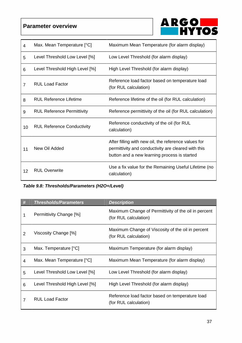
With the Thresholds/Parameters settings the RUL calculation can be configured and the alarm
thresholds can be set.
# Thresholds/Parameters Description
1 Permittivity Change [%] Maximum Change of Permittivity of the oil in percent
(for RUL calculation)
2 Conductivity Change [%] Maximum Change of Conductivity of the oil in
percent (for RUL calculation)
3 Max. Temperature [°C] Maximum Temperature (for alarm display)
Parameter overview
37
4 Max. Mean Temperature [°C] Maximum Mean Temperature (for alarm display)
5 Level Threshold Low Level [%] Low Level Threshold (for alarm display)
6 Level Threshold High Level [%] High Level Threshold (for alarm display)
7 RUL Load Factor Reference load factor based on temperature load
(for RUL calculation)
8 RUL Reference Lifetime Reference lifetime of the oil (for RUL calculation)
9 RUL Reference Permittivity Reference permittivity of the oil (for RUL calculation)
10 RUL Reference Conductivity Reference conductivity of the oil (for RUL
calculation)
11 New Oil Added
After filling with new oil, the reference values for
permittivity and conductivity are cleared with this
button and a new learning process is started
12 RUL Overwrite Use a fix value for the Remaining Useful Lifetime (no
calculation)
Table 9.8: Thresholds/Parameters (H2O+/Level)
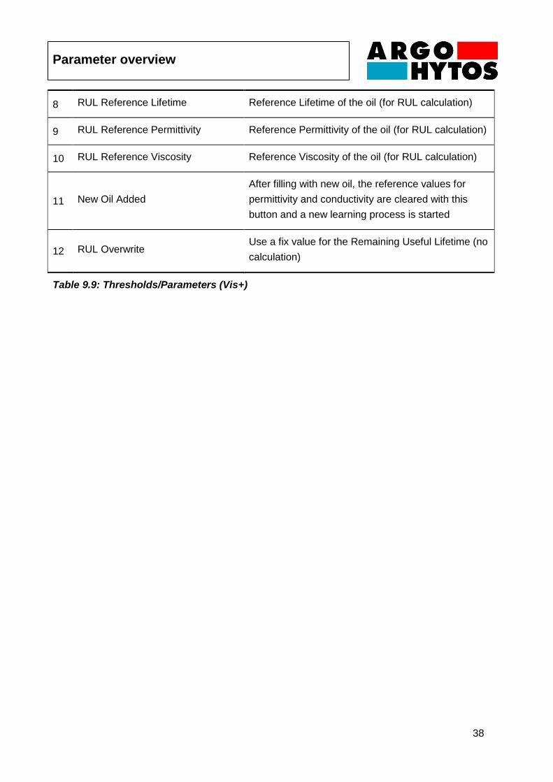
# Thresholds/Parameters Description
1 Permittivity Change [%] Maximum Change of Permittivity of the oil in percent
(for RUL calculation)
2 Viscosity Change [%] Maximum Change of Viscosity of the oil in percent
(for RUL calculation)
3 Max. Temperature [°C] Maximum Temperature (for alarm display)
4 Max. Mean Temperature [°C] Maximum Mean Temperature (for alarm display)
5 Level Threshold Low Level [%] Low Level Threshold (for alarm display)
6 Level Threshold High Level [%] High Level Threshold (for alarm display)
7 RUL Load Factor Reference load factor based on temperature load
(for RUL calculation)
Parameter overview
38
8 RUL Reference Lifetime Reference Lifetime of the oil (for RUL calculation)
9 RUL Reference Permittivity Reference Permittivity of the oil (for RUL calculation)
10 RUL Reference Viscosity Reference Viscosity of the oil (for RUL calculation)
11 New Oil Added
After filling with new oil, the reference values for
permittivity and conductivity are cleared with this
button and a new learning process is started
12 RUL Overwrite Use a fix value for the Remaining Useful Lifetime (no
calculation)
Table 9.9: Thresholds/Parameters (Vis+)

Troubleshooting
39
10. Troubleshooting
Error: No sensor communication via CAN
Cause Step
Cable is not correctly connected First ensure that the electrical connections of
the sensor, i.e. the data cable and power
cable, have been correctly connected. Ensure
that the connection is configured as
prescribed.
Wrong cable or cable is defective If possible use the ARGO-HYTOS data cable
Operating voltage is outside of the
prescribed range
Operate the sensor in the range between 12
and 28 VDC.
CAN interface of the connected sensors
is not activated
Activate the CAN interface using either
LubConfig or a terminal program as described
in the sensor manuals.
CAN interface of the LubMon Connect /
the connected sensors is not configured
properly
Check your CAN settings. The configuration
of the LubMon connect is depending on the
configuration of the sensors. Use the same
baud rate and activate the CAN mode of the
sensors. Be sure to use an own node ID for
every device.
Error: No communication via Ethernet
Cause Step
Cable is not correctly connected Check the correct electrical connection of the
Ethernet cable. Please mind the specified pin
assignment.
Firewall blocks data transmission /
reception
Release the following packages in your
firewall: UDP package from Gateway Port
8002 to Port 22463 of the portal
argohytos.remoteportal.de (static IP:
85.214.134.214). UDP response package of
Troubleshooting
40
the portal from Port 22463 of the portal to Port
8002 of the Gateway.
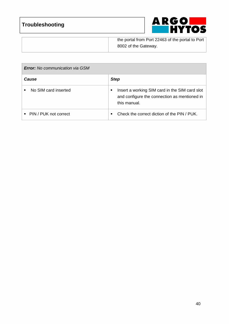
Error: No communication via GSM
Cause Step
No SIM card inserted Insert a working SIM card in the SIM card slot
and configure the connection as mentioned in
this manual.
PIN / PUK not correct Check the correct diction of the PIN / PUK.
Accessories
41
11. Accessories
Anchoring clip for slim side Description: Anchoring clip for the slim side of the LubMon Connect (acc. to Figure 5.1) Order code: SCSO 700-5010 Anchoring clip for wide side Description: Anchoring clip for the wide side of the LubMon Connect (acc. to Figure 5.1) Order code: SCSO 700-5020 NOTE: More accessories are listed in Chapter 7 – Commissioning the Gateway (Table 7.1).
Contact address
42
12. Contact address
ARGO-HYTOS GMBH
Produktbereich Sensor- & Messtechnik
Industriestraße 9
D-76703 Kraichtal-Menzingen
Tel. +49-7250-76-0
Fax +49-7250-76-575
E-mail: [email protected]
EG declaration of conformity
43
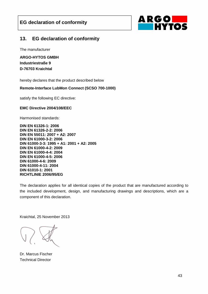
13. EG declaration of conformity
The manufacturer
ARGO-HYTOS GMBH
Industriestraße 9
D-76703 Kraichtal
hereby declares that the product described below
Remote-Interface LubMon Connect (SCSO 700-1000)
satisfy the following EC directive:
EMC Directive 2004/108/EEC
Harmonised standards:
DIN EN 61326-1: 2006 DIN EN 61326-2-2: 2006 DIN EN 55011: 2007 + A2: 2007 DIN EN 61000-3-2: 2006 DIN 61000-3-3: 1995 + A1: 2001 + A2: 2005 DIN EN 61000-4-2: 2009 DIN EN 61000-4-4: 2004 DIN EN 61000-4-5: 2006 DIN 61000-4-6: 2009 DIN 61000-4-11: 2004 DIN 61010-1: 2001 RICHTLINIE 2006/95/EG
The declaration applies for all identical copies of the product that are manufactured according to
the included development, design, and manufacturing drawings and descriptions, which are a
component of this declaration.
Kraichtal, 25 November 2013
Dr. Marcus Fischer
Technical Director
Change Log
44
14. Change Log
17.04.2013: V1.10.13 – Konformitätserklärung und Change Log hinzugefügt, Kapitel über die
darstellbaren Parameter erstellt, Verbesserungen in Kapitel 10 (Fehlerbehebung), diverse
allgemeine Ergänzungen und Verbesserungen. /AW
25.11.2013: V1.20.13 – Verbesserungen in Kapitel 9 (Fehlerbehebung), neue Screenshots in
Kapitel 7, neues Anschlussbild in Kapitel 7, Zubehörliste aktualisiert, Quickstart aktualisiert /AW