Embed Size (px)
Citation preview
Background: Though vertebroplasty is a well-known and extremely effective proce-dure in experienced hands, it is a much more difficult procedure to learn than standard spinal pain injection procedures. We therefore present a simplified, methodical approach to vertebroplasty that can be adopted by trained interventionalists. Many practitioners who attend hands-on cadaver workshops lack confidence to apply this technique in live patients.
Objectives: To present a methodical, reproducible, and proven technique. To provide strategies on pre-procedure and post-procedure care in order to optimize outcomes in vertebroplasty patients.
Study Design: A step-by-step tutorial is presented outlining the steps in the vertebro-plasty procedure. A discussion of anatomic considerations, pre-procedure patient selec-tion issues, and post-procedure management is also presented.
Methods: Sections are presented on anatomy, patient selection, a 10-step technique on performance of vertebroplasty, a discussion of how this technique is advantageous, and post-procedure management.
Results: This technique has been proven in clinical practice for over 1,500 vertebroplas-ties and has been well-received the past 4 years by hundreds of trainees taught at nu-merous hands-on courses (Stryker Interventional Pain, Arthrocare, and Society of Inter-ventional Radiology).
Conclusion: A basic tutorial is presented for the beginner who is interested in vertebro-plasty. This safe and reproducible technique has been proven in clinical practice. The an-atomic considerations, patient selection issues, technique, and post-procedure manage-ment has been taught and well received by hundreds of physicians at numerous hands on courses within the United States and Canada.
Key words: vertebroplasty, fluoroscopic anatomy, PMMA
Pain Physician 2007; 10:367-380
Technical Review
Vertebroplasty: A Systematic Approach
Mubin I. Syed1,2, MD and Azim Shaikh2, MD
www.painphysicianjournal.com
Pain Physician 2007; 10:367-380 • ISSN 1533-3159
Pain Physician: March 2007:10:367-380
368 www.painphysicianjournal.com
Vertebroplasty was introduced in 1987 by Gallbert et al for the treatment of painful cervical hemangioma (1). The first American
experience was published by Jensen et al in 1997 (2).Since then, there has been an explosion of interest in this remarkable procedure, which can be useful for the majority of vertebral fractures throughout the spinal column. The procedure has been approved by Medicare since 2001. FDA approved cements have been available since 2004. Though this is a well-known and effective procedure (level III evidence) in experienced hands, it is a much more difficult procedure to learn than standard spinal pain injection procedures. We therefore present a simplified, methodical approach to vertebroplasty that can be easily adopted by any trained interventionalist (3). Many practitioners attend hands-on cadaver workshops only to lack confidence with live patients. We believe that much of this lack of confidence is due to the lack of a methodical and reproducible technique. In this article, we attempt to present an easy technique that has been proven in clinical practice for more than 1,500 levels and has been well-received by hundreds of novices at numerous hands-on courses (Stryker Interventional Pain, Arthrocare, and Society of Interventional Radiology).
ANATOMIC CONSIDERATIONS
An understanding the fluoroscopic anatomy of the vertebral column is critical for the vertebroplasty procedure. The target for needle placement is the vertebral body, which is visualized fluoroscopically as having a superior and inferior endplate in the AP (anteroposterior) projection. The lateral margins are also visualized as somewhat concave margins. Medial to the lateral margins of the vertebral body are the ovoid or circular pedicular margins. It is critical to ap-preciate the medial cortex on the AP projection. The superior and inferior margin of the pedicle is also im-portant to appreciate. In the thoracic vertebrae, the margin of the rib head can be identified as a structure just lateral to the lateral margin of the pedicle.
In the lateral projection, the superior, inferior, and anteroposterior margins of the vertebral body are easily seen. A serious attempt should be made to obtain the true lateral projection by displaying all of these margins sharply. It is mandatory to superimpose the right and left ribs to obtain the true lateral projec-tion. The superior and inferior endplates may require skewing (in the coronal plane) the C-arm. The superior
and inferior margins of the pedicle should also be ap-preciated as it is critical for the needle not to traverse the inferior margin.
The vertebroplasty procedure, unlike most spine procedures, involves traversing the neural arch past the spinal canal into the vertebral body. This must be done in an extremely reliable, precise, accurate, and safe manner due to the potentially devastating con-sequences to the patient. The basic structures of the neural arch include the spinous process (posterior mid-line) and the lamina (which emanate from the spinous processes anterolaterally). These join on each side to form the pedicle, which extends anteriorly on each side to join the vertebral body. The pedicle diameter is variable, but generally increases in size from the tho-racic spine to the lumbar spine. They are located in the superior portion of the vertebrae. The tranverse pro-cesses extend laterally in the lumbar spine and pos-terolaterally in the thoracic spine from the junction of the pedicle and the lamina.
Leakage of cement can occur in various directions. The most dreaded leakage is posteriorly into the epi-dural space. This is easily controlled by constant flou-roscopic monitoring of the cement form in relation to the posterior vertebral body margin, and by keeping a safety margin anterior to this margin. Generally, leak-age in this direction occurs via the basivertebral plexus into the epidural vein. Another site of leakage may be the paravertebral veins which are generally seen as a round or tubular structure emanating anteriorly from the vertebral body or superimposed over the vertebral body in the lateral projection. Another common site of leakage is intradiscal leakage extending beyond the superior or inferior endplates. It is usually globular in appearance but may outline the endplate adjacent to the disk. Lastly, leakage may also occur anterior or lateral to the vertebral body margin in a globular fashion. Fortunately the vast majority of leakages are asymptomatic (4).
The structures anterior to the vertebral body of major concern are the aorta and the inferior vena cava. Since the vertebral body is a cylindrical object, the needle should never be advanced to the anterior margin of the vertebral body in the lateral projec-tion. In fact, a safety margin of approximately 1cm from the anterior border should be used for final trocar tip placement in the lateral projection. This should be confirmed with the AP projection, and if the trocar tip is truly at the midline, the tip can ad-vanced further.
www.painphysicianjournal.com 369
Vertebroplasty: A Systematic Approach
PATIENT SELECTION AND EVALUATION
A complete history and physical exam should be performed on each patient. The exam may be done un-der fluoroscopy to elicit point tenderness over or near the fracture site. A caveat is that patients with obvious compression fracture may not have point tenderness when on high dose narcotics. Always exclude sacroiliac and facet joint tenderness as the cause of the patient’s acute pain, since these can be treated with procedures that are much less invasive than vertebroplasty. Anoth-er advantage of the fluoroscopic exam is that unsus-pected vertebral fractures which are the major source of the patient’s pain can be identified. Furthermore, fluoroscopic exam can target further imaging.
Traumatic vertebral compression fractures in young, otherwise healthy patients should not be treated initially with vertebroplasty. These patients usually respond to conservative therapy and the long-term effects of vertebroplasty are not known.
It is of paramount importance that the patient must be able to tolerate a prone position. If this is not possible consider anesthesia support.
An ideal first patient for the beginner should be an osteoporotic patient with 1/3 to 1/2 of vertebral body height loss. Furthermore, malignancy should be avoided early in one’s experience. Infection is a con-traindication and should be avoided by all practitio-ners, no matter what level of experience. Infection includes vertebral osteomyelitis / epidural abscess or other systemic or local infections such as a urinary tract infection. This is because any untreated infec-tion could potentially seed the Polymethylmethac-rylate (PMMA), which is a foreign body that cannot be easily removed. Consideration should be made for antibiotic in the PMMA for immunocompromised or debilitated patients. We often use vancomycin or tobramycin. However, most practitioners do not routinely add antibiotic to the PMMA mixture. In the male patient who does not have an underlying cause for osteoporosis, it is important to exclude malignan-cy with a biopsy (5).
It is also important to ensure that the margins of the spinal canal are intact. A spinal canal that is not intact could allow the cement to extrude from the ver-tebral body into the epidural space.
In the situation of multiple compression fractures, there are usually only 1 or 2 fractures that are acute or subacute. This can be determined by a MRI T1 and
STIR image sequences demonstrating marrow edema. However, in a few patients, MRI may not be possible due to a pacemaker, ICD, or recently placed stent, etc. As a second choice, a bone scan may demonstrate in-tense focal uptake at the acute or subacute fracture site. An important caveat is that the bone scan may be negative in the first several days and may even be negative up to 2 weeks after the fracture in elderly patients due to an impaired healing response (6). A bone scan may be positive for up to 2 years post-frac-ture. A CT will need to supplement the bone scan to exclude retropulsion. Occasionally, an acute fracture may be seen on a CT manifested by end plate fracture lines and paravertebral soft tissue density at the frac-ture level.
Multilevel vertebroplasty should be avoided in patients with low cardiopulmonary reserve (COPD on home oxygen or congestive heart failure with a low ejection fraction). When vertebroplasty is performed on these patients, it should be done with extreme care with only 1 level treated and strict attention paid to cement volumes. This is because these patients are at high risk for symptomatic bone marrow embolism / fat embolism (7).
TECHNIQUE
Our 10-step technique involves the following:Step 1: Anatomic orientation
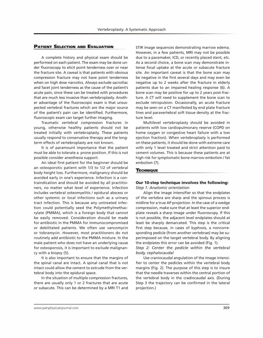
Align the image intensifier so that the endplates of the vertebra are sharp and the spinous process is midline for a true AP projection. In the case of a wedge compression, make sure that at least the superior end-plate reveals a sharp image under fluoroscopy. If this is not possible, the adjacent level endplates should at least be sharply demarcated. This step is the critical first step because, in cases of kyphosis, a noncorre-sponding pedicle (from another vertebrae) may be su-perimposed on the target vertebral body. By aligning the endplates this error can be avoided (Fig. 1).Step 2: Center the pedicle within the vertebral body, cephalocaudal
Use craniocaudal angulation of the image intensi-fier to center the pedicles within the vertebral body margins (Fig. 2). The purpose of this step is to insure that the needle traverses within the central portion of the vertebral body in the cradiocaudal axis. (During Step 3 the trajectory can be confirmed in the lateral projection.)
Pain Physician: March 2007:10:367-380
370 www.painphysicianjournal.com
Step 3: Offsetting the trocar so that the needle tip is not obscured by the hub of the trocar
A 5° lateral oblique view of the hub is achieved by rotating the image intensifier 5° laterally (Fig. 3A).
Fig. 1: Anatomic Orientation: Align image intensifier so
that the endplates of the vertebra are sharp and the spinous
process is midline for a true AP projection.
Fig. 2: Center the pedicle within the vertebral body, cepha-
locaudal.
Fig. 3: A. A 5° lateral oblique view of the hub is achieved by rotating the image intensifier 5° laterally. B. The lateral margin
of the pedicle is targeted. The needle is then advanced to this point along the axis of the image intensifier (“gun barreled”). The
needle is then embedded 2–3mm into the bone using either an orthopedic mallet or hand screwing motion.
A 13-gauge bevel tipped needle is then selected. (Al-ternatively a diamond tipped needle can be used, but Step 8 then must be omitted.) The lateral margin of the pedicle is targeted by the needle in this projection
A. B.
www.painphysicianjournal.com 371
Vertebroplasty: A Systematic Approach
at the 9 o’clock position for a left-sided approach and the 3 o’clock position for the right-sided approach. The needle is then advanced to this point along the axis of the image intensifier (“gun barreled”). The needle is then embedded 2–3mm into the bone using either an orthopedic mallet or hand screwing motion (Fig. 3B). The purpose 5º obliquity is to slightly offset the needle hub from the needle tip in the AP projection. This prevents the hub of the needle from obscuring the medial cortex in the AP projection during needle or trocar advancement. Step 4: Trocar advancement through the pedicle
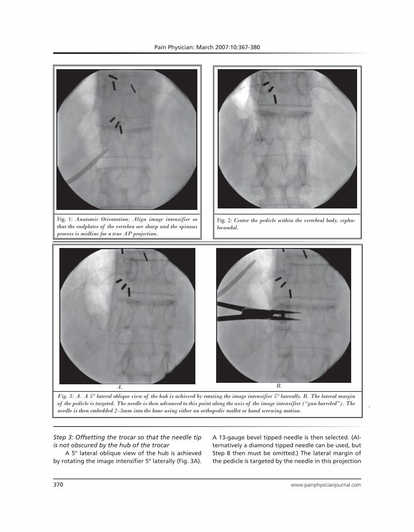
The image intensifier is turned back to the the AP projection as in Step 2. The trocar tip is now easily visu-alized with respect to the medial cortex of the pedicle (FIg. 4A). Real time fluoroscopy in the AP and lateral projections should be utilized to advance the trocar to the midline of the pedicle. The purpose of advancing the trocar only to the midline of the pedicle is to pre-vent overshooting the vertebral body (Fig. 4B). This step will correct for variations in pedicle length and vertebral body AP dimensions.
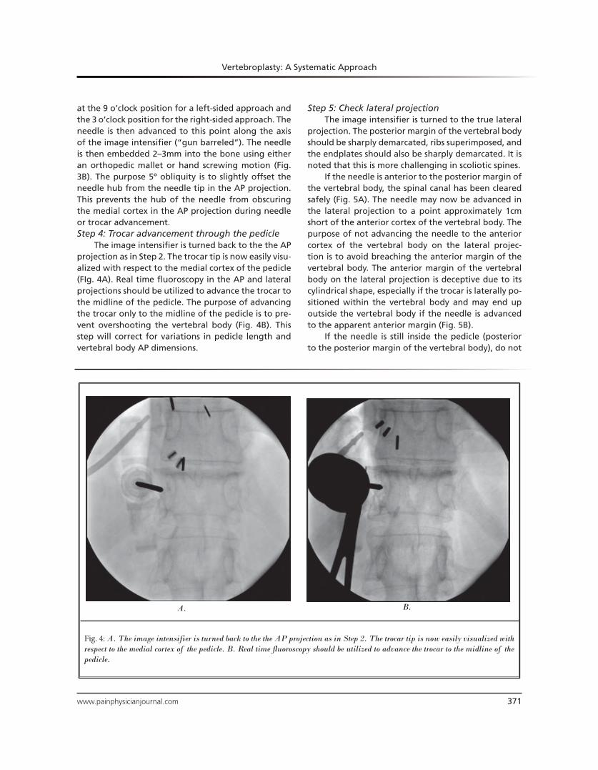
Step 5: Check lateral projectionThe image intensifier is turned to the true lateral
projection. The posterior margin of the vertebral body should be sharply demarcated, ribs superimposed, and the endplates should also be sharply demarcated. It is noted that this is more challenging in scoliotic spines.
If the needle is anterior to the posterior margin of the vertebral body, the spinal canal has been cleared safely (Fig. 5A). The needle may now be advanced in the lateral projection to a point approximately 1cm short of the anterior cortex of the vertebral body. The purpose of not advancing the needle to the anterior cortex of the vertebral body on the lateral projec-tion is to avoid breaching the anterior margin of the vertebral body. The anterior margin of the vertebral body on the lateral projection is deceptive due to its cylindrical shape, especially if the trocar is laterally po-sitioned within the vertebral body and may end up outside the vertebral body if the needle is advanced to the apparent anterior margin (Fig. 5B).
If the needle is still inside the pedicle (posterior to the posterior margin of the vertebral body), do not
Fig. 4: A. The image intensifier is turned back to the the AP projection as in Step 2. The trocar tip is now easily visualized with
respect to the medial cortex of the pedicle. B. Real time fluoroscopy should be utilized to advance the trocar to the midline of the
pedicle.
A. B.
Pain Physician: March 2007:10:367-380
372 www.painphysicianjournal.com
A. B. C.
Fig. 5. A. Lateral projection: The posterior margin of the vertebral body should be sharply demarcated, ribs superimposed, and
the endplates should also be sharply demarcated. If the needle is anterior to the posterior margin of the vertebral body, the spinal
canal has been cleared safely. B. The needle may now be advanced in the lateral projection to a point approximately 1cm short of
the anterior cortex of the vertebral body. C.If the needle is still inside the pedicle (posterior to the posterior margin of the vertebral
body), do not advance the needle in the lateral projection.
Fig. 6. Turn the image intensifier to the AP projection as in
Step 2 and 4. Advance the trocar to a point 1-2mm short of
the medial cortex of the pedicle.
advance the needle in the lateral projection (Fig. 5c). Proceed to Step 6 if the needle is still posterior to the posterior margin of the vertebral body. Step 6: Continued trocar advancement through the pedicle
Turn the image intensifier to the AP projection as in Step 2 and 4. Advance the trocar to a point 1–2mm short of the medial cortex of the pedicle (Fig. 6). Step 7: Check lateral projection
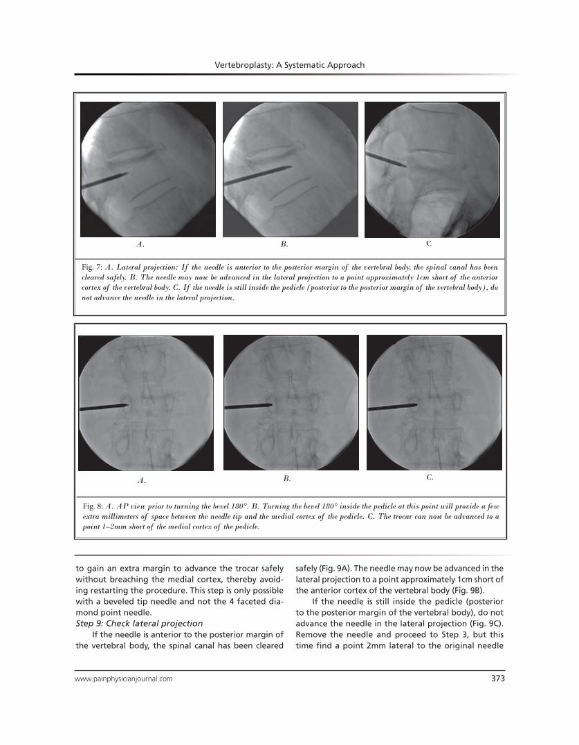
If the needle is anterior to the posterior margin of the vertebral body, the spinal canal has been cleared safely (Fig. 7A). The needle may now be advanced in the lateral projection to a point approximately 1cm short of the anterior cortex of the vertebral body (Fig. 7B).
If the needle is still inside the pedicle (posterior to the posterior margin of the vertebral body), do not advance the needle in the lateral projection (Fig. 7C). Proceed to Step 8.Step 8: Turn the bevel 180°
Turning the bevel 180° inside the pedicle at this point will provide a few extra millimeters of space between the needle tip and the medial cortex of the pedicle (Fig. 8A and Fig. 8B). The trocar can now be advanced to a point 1–2mm short of the medial cortex of the pedicle (Fig. 8C). This step allows the operator
www.painphysicianjournal.com 373
Vertebroplasty: A Systematic Approach
Fig. 7: A. Lateral projection: If the needle is anterior to the posterior margin of the vertebral body, the spinal canal has been
cleared safely. B. The needle may now be advanced in the lateral projection to a point approximately 1cm short of the anterior
cortex of the vertebral body. C. If the needle is still inside the pedicle (posterior to the posterior margin of the vertebral body), do
not advance the needle in the lateral projection.
A. B.C
Fig. 8: A. AP view prior to turning the bevel 180°. B. Turning the bevel 180° inside the pedicle at this point will provide a few
extra millimeters of space between the needle tip and the medial cortex of the pedicle. C. The trocar can now be advanced to a
point 1–2mm short of the medial cortex of the pedicle.
A. B. C.
to gain an extra margin to advance the trocar safely without breaching the medial cortex, thereby avoid-ing restarting the procedure. This step is only possible with a beveled tip needle and not the 4 faceted dia-mond point needle. Step 9: Check lateral projection
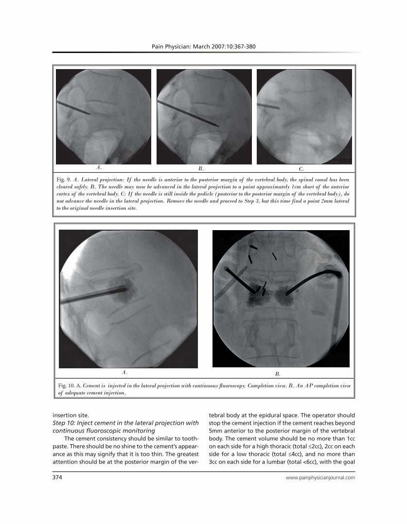
If the needle is anterior to the posterior margin of the vertebral body, the spinal canal has been cleared
safely (Fig. 9A). The needle may now be advanced in the lateral projection to a point approximately 1cm short of the anterior cortex of the vertebral body (Fig. 9B).
If the needle is still inside the pedicle (posterior to the posterior margin of the vertebral body), do not advance the needle in the lateral projection (Fig. 9C). Remove the needle and proceed to Step 3, but this time find a point 2mm lateral to the original needle
Pain Physician: March 2007:10:367-380
374 www.painphysicianjournal.com
Fig. 9. A. Lateral projection: If the needle is anterior to the posterior margin of the vertebral body, the spinal canal has been
cleared safely. B. The needle may now be advanced in the lateral projection to a point approximately 1cm short of the anterior
cortex of the vertebral body. C: If the needle is still inside the pedicle (posterior to the posterior margin of the vertebral body), do
not advance the needle in the lateral projection. Remove the needle and proceed to Step 3, but this time find a point 2mm lateral
to the original needle insertion site.
A. B. C.
Fig. 10. A. Cement is injected in the lateral projection with continuous fluoroscopy. Completion view. B. An AP completion view
of adequate cement injection.
A. B.
insertion site. Step 10: Inject cement in the lateral projection with continuous fluoroscopic monitoring
The cement consistency should be similar to tooth-paste. There should be no shine to the cement’s appear-ance as this may signify that it is too thin. The greatest attention should be at the posterior margin of the ver-
tebral body at the epidural space. The operator should stop the cement injection if the cement reaches beyond 5mm anterior to the posterior margin of the vertebral body. The cement volume should be no more than 1cc on each side for a high thoracic (total ≤2cc), 2cc on each side for a low thoracic (total ≤4cc), and no more than 3cc on each side for a lumbar (total <6cc), with the goal
www.painphysicianjournal.com 375
Vertebroplasty: A Systematic Approach
being top to bottom filling on each side (Fig. 10A and Fig. 10B) (8,9). If the cement leaks into a tubular struc-ture, stop injection since this may be a paravertebral vein. Note that this may occur transiently; therefore continuous fluoroscopic guidance is mandatory. If the operator is uncertain, he/she may check in the AP view, but should never inject in the AP projection. Ideally, in the AP projection cement distribution should be in the lateral a third of the vertebrae on both sides. If this is not possible, it is acceptable to distribute the cement in the central third with extension to one of the lateral thirds of the vertebrae (9).
DISCUSSION
The weakness of other published techniques is that they simply state that a transpedicular approach is performed without adequately describing what is entailed during the actual advancement of the needle and how to avoid entering the spinal canal.
The first step of aligning the endplates and setting the spinous process in the center is rarely described. Like Han et al, we find this to be critical for anatomic orientation of our target vertebrae (10). In the ky-photic patient with multiple compression fractures, it is very common for the pedicle of another vertebrae to be superimposed upon the pedicle of an adjacent vertebrae in the straight AP projection. Not correcting for this could result in the needle traversing the neuro foramina thereby causing nerve root damage, epidu-ral space entry, hematoma formation, or entry into an adjacent vertebra.
Step 2, centering the pedicle within the vertebral body, is again rarely described. This needle placement centrally within the vertebral body is critical in more severely compressed vertebrae where there is little margin for error.
Step 3 is again rarely described in the literature, and quantification of the angle of entry has previously never been noted (11). Like Zoarski et al, we find that slightly offsetting the trocar hub from the needle tip allows us to visualize the relationship of the needle tip to the critical landmark of the medial cortex of the pedicle constantly in the AP projection (11). We have found that a quantified 5-degree angulation is best in preventing false starts. It is to be understood that this technique is still transpedicular, not parapedicular, because the needle still traverses the pedicle, but in a slight obliquity.
The purpose of Step 4 is to prevent overshooting the vertebral body during trocar advancement. Fre-
quent lateral checks for the beginner may be helpful even before this point is reached to instill confidence in needle position. The concern of overshooting the vertebral body is theoretically unlikely because the smaller the vertebral body, the smaller the pedicle and conversely the larger the diameter the pedicle, the larger the vertebral body.
The purpose of Step 5 is to check the depth of the needle in the AP dimension. It is important to empha-size the appearance of the true lateral projection. This is rarely described in the literature for the vertebro-plasty technique. The superior and inferior endplates should be sharply demarcated. By “skewing” the C-arm in the sagittal plane, the anterior and posterior vertebral margins should be sharply demarcated by rotating the C-arm in the axial plane. This step is criti-cal in determining whether the posterior margin of the vertebral body is truly cleared and also to get a true assessment of the position of the trocar within the vertebral body in the craniocaudal axis. It is recog-nized that this is particularly difficult in the scoliotic patient, but it is still just as important.
The purpose of Step 6 is to continue advancement toward the vertebral body if the spinal canal is not yet cleared. This is to be done with constant complete visualization of the trocar tip in relation to the me-dial cortex of the pedicle. The importance of this step was previously described by Zoarski et al and Renfrew (11,12). In most other described techniques, the hub of the needle obscures the tip of the trocar and the me-dial cortex in the AP projection since a “down the bar-rel” approach is used. Our technique is distinguished by quantifying a reliable angle of shallow obliquity for the beginner.
The purpose of Step 7 is to advance the trocar within the vertebral body once the spinal canal is cleared. This can be done safely in the lateral projec-tion. It is important due to the relatively lateral posi-tion of the trocar within the vertebral body that the needle not be advanced to the anterior margin of the vertebral body since the vertebral body is a cylinder. We therefore recommend a margin of approximately 1cm from the anterior margin. Other recommended margins include the anterior fourth from Kallmes et al, within the anterior third from Mathis et al, and the junction between the anterior and middle third from Zoarski et al and Jensen et al, and within the anterior quarter to anterior third from Peh and Gilu-la (2,11,13-15). As a precautionary note, if the trocar is initially easy to advance and then becomes difficult
Pain Physician: March 2007:10:367-380
376 www.painphysicianjournal.com
to advance anteriorly, it is prudent to stop advancing the needle since the cortex of the anterior aspect of the vertebral body may be reached.
The purpose of Step 8 is to create additional space to clear the spinal canal by rotating the beveled tipped needle 180 degrees. We found this step to be unique in the literature. This step can potentially prevent hav-ing to restart the procedure. However, it can only be done with a beveled tip needle.
Step 9 is similar to Step 5. The purpose of Step 10 is to safely deliver the
cement into the vertebral body. We emphasize the importance of continuous fluoroscopy since cement intravasation may be transient and not otherwise detected. We also noted the ideal volume of cement that should be delivered. Like Belkoff, Zoarski, and Mathis, we believe in not overfilling the vertebral body with cement as this could predispose to adjacent vertebral fractures and complications from leakage (8,11,14,16,17). It has been shown that biomechanical strength and stiffness comparable to normal bone can be achieved with the previously recommended vol-ume of cement delivery depending on the vertebral level (17).
The key differences between our technique and other techniques reported in the medical literature are: 1. The establishment of the anatomic orientation as
Step 1.2. The ability to constantly visualize the medial cor-
tex of the pedicle (a critical landmark) in the AP projection during needle placement without ob-scuring the needle tip and medial cortex by the needle hub.
3. The obliquity of the needle path is not so great from the vertical so as to result in multiple false starts.
4. The beveled tips add directionality to the trocar which may be further useful in avoiding false starts and also in treating vertebrae plana (severe vertebral body compression fracture in which the vertebral body is in the shape of a thin disc) where it is critical to stay within the vertebral body mar-gins in the cephalocaudal axis. Presented below are potential critiques of our
technique and how we have addressed these con-cerns.1. The needle could advance beyond the anterior
vertebral body margin since only the AP and slight oblique views are used to advance the needle ini-tially. This is corrected by checking the lateral pro-
jection when the needle tip crosses the midline of the pedicle in the AP projection.
2. The 180o twist of the beveled needle could poten-tially cause a pedicle fracture. Although we have never experienced this, it is theoretically possible in an osteoporotic patient. A modification of technique to avoid this may involve not twisting the needle itself, but to simply remove the stylet, turn it 180o outside of the patient, and place it back through the trocar. This may not be possible with some trocar types.
POST PROCEDURE PATIENT MANAGEMENT
Immediate increased pain after vertebroplas-ty with ideal technique1. Hold pressure immediately after removal of the
needle from the puncture site for approximately 10 minutes. This step avoids the patient experi-encing pain from soft tissue bleeding.
2. Sit the patient more upright.3. If pain persists, consider narcotic therapy. 4. If pain persists after 2 hours, consider CT imaging
to exclude a complication. Pain may occur immediately or within a few hours
post vertebroplasty at the puncture site. This can of-ten be avoided by holding manual compression at the puncture site for approximately 10 minutes immedi-ately after trocar removal. This controls for any soft tissue bleeding that we believe is a source for this pain.
Another source of moderate or severe pain may be the patient lying in a supine position. This can im-mediately be corrected by raising the head of the bed up to 40 degrees until the patient is comfortable. If the pain continues despite these measures, narcotics can be administered until the patient is ready to am-bulate. Often patients feel dramatic relief in their post procedure pain by resuming the upright position and even ambulating. In fact, this is when patients often notice dramatic improvement compared to their pre-procedure pain.
If pain persists after 2 hours, consider CT imaging to exclude a complication. Complications could include a retroperitoneal hematoma from an extrapedicular approach, a pedicle fracture, or soft tissue hemato-ma. Cement leakage into the spinal canal or neural foramina can also result in severe pain or neurologi-cal deficits. Neurosurgical consultation is necessary if this occurs. Steroid infusion as per spinal cord injury
www.painphysicianjournal.com 377
Vertebroplasty: A Systematic Approach
protocol should be considered at this point or imme-diately when the operator realizes that this has oc-curred. Radicular pain due to nerve root injury can be managed with selective nerve root block as an initial short term solution. Idiopathic pain can uncommonly be seen after vertebroplasty without an associated ce-ment leak or hematoma. The etiology of this may be local ischemia or pressure in the intratrabecular space during injection. This pain is usually self limited with resolution occurring within a few hours (18).
Delayed pain or lack of relief after vertebro-plasty and how to treat1. New fracture or refracture (refracture occurs due
to inadequate cement filling). (Counsel osteopo-rotic patients ahead of time regarding their in-creased risk for new fractures that are often adja-cent. Approximately 20% of osteoporotic fracture patients have another fracture in 1 year. Steroid patients have almost twice this risk.)
2. Any patient experiencing delayed lower extrem-ity weakness or bladder / bowel incontinence should be immediately imaged and referred to a spine surgeon even if their physical exam is nega-tive. The natural history of compression fractures is continued compression with resulting increased retropulsion. This continued compression can oc-cur even despite vertebroplasty several months later (19).
3. Facet syndrome or SI joint syndrome.4. Costovertebral point tenderness also may repre-
sent thoracic facet syndrome. 5. Pedicle fracture (Theoretically pediculoplasty can
help versus conservative treatment).6. Infection can be avoided by a. Antibiotic in cement in immunocompromised
patients b. IV antibiotic prior to procedure c. Refer to a spine surgeon and infectious dis-
ease specialist if infection occurs.
Delayed pain or lack of pain relief after ver-tebroplasty
Patients may complain of no relief following the vertebroplasty. Alternatively, they may report initial dramatic improvement followed by worsening. Either of these 2 scenarios should be managed similarly. It is to be realized that the immediate relief postproce-dure may simply be a result of local anesthesia as well as persistent effects of sedatives, even if these agents
are supposed to be short acting. A 24-hour follow-up is therefore important to distinguish true relief from the procedure versus masking of pain by the intrapro-cedural medications.
Delayed pain or lack of relief after vertebroplasty can be managed in the following manner. The first step is to identify the source of the pain. We have found the examination under fluoroscopy to be ex-tremely helpful to target further imaging.
Common sources of lack of relief or delayed pain are a new fracture or refracture. If there is no pain relief within the first week, this possibility should be considered. A new fracture or refracture can manifest as persistent point tenderness and pain at the same region as the treated site. The patient may complain of a different location of pain if the fracture is nonad-jacent. Early on these fractures may be subtle but of-ten are visible fluoroscopically. Usually, but not always the pain pattern for a new fracture is that of relief in the pain followed by recurrent pain. Recurrent pain may often be more severe than the initial pain due to the acuteness of the fracture. A new fracture at an adjacent or nonadjacent level once confirmed can be treated with vertebroplasty.
If the fracture is adjacent, the pain is usually iden-tical to the original pain. Examination under fluo-roscopy may be helpful in eliciting the exact site of point tenderness. This can be followed up with cross sectional imaging. MRI is the best imaging modality since very subtle early fractures can be seen that are radiographically occult. It is therefore critical for the operator to review the MRI with the comparison MRI, even if the radiology interpretation is negative. The second best modality is CT imaging combined with nuclear medicine bone scanning.
Another scenario is that of recurrent fracture at the same level. This is usually due to inadequate cement filling. Again the patient will complain of either no relief, partial relief, or relief followed by recurrent pain at the same site. Examination under fluoroscopy will usually demonstrate point tender-ness at the vertebroplasty site. Furthermore, there may be some interval height loss at the treated ver-tebrae. This can often be corrected by additional ce-ment placement to produce a top to bottom column of cement. This is a relatively advanced technique and may require referral to a more experienced op-erator (20).
Patients are at approximately 20% risk for new symptomatic fractures that are often adjacent (21).
Pain Physician: March 2007:10:367-380
378 www.painphysicianjournal.com
Therefore, it is wise to counsel patients ahead of time regarding this risk. Patients taking glucocorticoids have almost twice this risk (22).
Another common source of pain post vertebro-plasty is facet syndrome. This can often become un-masked following an adequate vertebroplasty. This can be diagnosed with point tenderness over the facet as well as attention to the history eliciting facet joint syndrome. The biomechanical explanation for facet syndrome following vertebroplasty is facet joint cap-sule overstretch due to kyphosis from the compression fracture (23). This may manifest as point tenderness lateral from the midline over the facet joint. In the thoracic vertebrae point tenderness over the costover-tebral joints may in fact represent thoracic facet syn-drome. A caveat is that a new vertebral body compres-sion fracture may elicit point tenderness localized to its corresponding facet, even unilaterally. It is therefore important to obtain an MRI or bone scan to exclude a fracture prior to any facet treatment if the recurrent pain is severe. A bone scan would be more specific for diagnosis of facet syndrome. As in standard practice, facet syndrome can be treated with facet blocks or medial branch blocks / facet denervation.
A rare source of pain at the vertebroplasty site is the pedicle fracture. It may be important to exclude this fracture preprocedure since it often seen in verte-brae plana. CT is the best imaging modality to dem-onstrate this type of fracture. Though we have never experienced this complication, this would typically re-quire conservative treatment. Pediculoplasty has been reported as a potential solution for this condition (24).
Another commonly seen source of pain post ver-tebroplasty is SI joint syndrome. It is critical in the os-teoporotic patient to distinguish sacral insufficiency fractures from sacroiliac joint syndrome. This may re-quire further imaging such as a bone scan. The “Hon-da” sign can be pathognomonic for a sacral insuffi-ciency fracture (25). A sacral insufficiency fracture can be treated with sacroplasty, whereas sacroiliac joint syndrome may require a sacroiliac joint injection.
One of the more dreaded complications is infec-tion. This would require neurosurgical management. This is an extremely rare occurrence and only recently reported in literature (26). The best approach is pre-vention. Strict aseptic technique should be conducted during all phases of the procedure. It is to be remem-bered, that unlike most spinal injections, a permanent foreign body is deposited in the vertebral body as part of the procedure. Therefore, a gown, hat, and mask,
are all highly recommended. Prevention of infection can also be enhanced by using antibiotic laden ce-ment (vancomycin or tobramycin), especially in the immunocompromised patient. Intravenous antibiotics (cephazolin) may also be administered preprocedure. It is also important to exclude any infection, local or systemic, prior to the vertebroplasty. Even a simple urinary tract infection should result in cancellation of the procedure until it has been properly treated and documentation of resolution of the infection has oc-curred. Furthermore, the imaging should be reviewed with an experienced radiologist to exclude discitis or vertebral osteomyelitis. If there is any doubt, a biopsy with culture and sensitivity should be first performed before vertebroplasty or if an infection is suspected. If the biopsy is positive, vertebroplasty should be avoid-ed at this site indefinitely or at least until clearance is given by a spine surgeon prepared to perform a cor-pectomy if infection recurs.
Any patient that experiences delayed lower extrem-ity weakness or bladder or bowel incontinence should be immediately imaged and referred to a spine surgeon, even if their physical exam is negative. The natural his-tory of compression fractures is continued compression with resulting increased retropulsion. This continued compression can occur, despite vertebroplasty.
MAINTENANCE THERAPY 1. Address the osteoporosis or underlying cause a. Dual Energy X-ray Absortiometry (DEXA)
scan and osteoporotic medications. b. Consider teriparatide (a parathyroid hormone
analogue) if multiple fracture c. Exclude secondary causes of osteoporosis if
the Z score is less than 2 standard deviations from the mean. Secondary causes should also be investigated if the bone mineral density is decreasing despite treatment with osteopo-rotic medications. Referral to an endocrinolo-gist or rheumatologist may be necessary in this situation.
2. Consider biopsy for multiple myeloma, if the pa-tient continues to have multiple fractures. Up to 10% of male patients have some other reason for vertebral fracture. It is of paramount importance to address the un-
derlying process responsible for the vertebral com-pression fracture. Typically, primary osteoporosis is the root cause, even in men. This must be diagnosed by performing DEXA scanning. Once diagnosed, pa-
www.painphysicianjournal.com 379
Vertebroplasty: A Systematic Approach
tients should be placed on calcium and vitamin D as well as appropriate medications for osteoporosis. In fact, according to the National Osteoporosis Foun-dation guidelines, any postmenopausal woman with a vertebral or hip fracture should be considered for osteoporosis treatment (27). We have experienced many patients who are untreated for osteoporosis by their primary care physicians in the setting of vertebral compression fractures simply because they do not meet the exact criteria for osteoporosis by bone mineral density (BMD).
A basic knowledge of DEXA scan interpretation is beneficial, since there is potential for false nega-tives (i.e. advanced degenerative disk disease). A low Z score in a patient should prompt referral to an en-docrinologist or rheumatologist to evaluate for sec-ondary causes of osteoporosis. Similarly, this should be done if the BMD is decreasing despite adequate treatment for osteoporosis. For patients who are on glucocorticoid therapy, efforts should be made to re-duce or taper the dose if at all possible.
For patients with multiple or recurrent fractures, teriparatide should be considered since the benefits of this therapy are seen within a few months.
A biopsy and workup for multiple myeloma should also be strongly considered in patients with multiple fractures. In male patients without a definable cause of osteoporosis, known metastatic disease, or a sig-nificant history of trauma, the routine performance of a vertebral biopsy through the vertebroplasty needle before the injection of bone cement is indicated to identify unexpected neoplasm (5).
CONCLUSION
In summary, we have attempted to create a basic tutorial for the beginner who is interested in verte-broplasty. We present a safe and reproducible tech-nique that has been proven in clinical practice. This technique and postprocedure management has been taught and well received by hundreds of physicians within the United States and Canada.
REFERENCES
Pain Physician: March 2007:10:367-380
380 www.painphysicianjournal com