Embed Size (px)
Citation preview

Published & Copyright © by
Ground Source Heat Pump Association National Energy Centre,
Davy Avenue, Knowlhill,
Milton Keynes MK5 8NG
T: 01908 354545 F: 01908 665577
Email: [email protected]
ClosedClosedClosedClosed----looplooplooploop Vertical Borehole Vertical Borehole Vertical Borehole Vertical Borehole
Design, Design, Design, Design, InInInInstallation & Materials Standardstallation & Materials Standardstallation & Materials Standardstallation & Materials Standardssss
Issue 1Issue 1Issue 1Issue 1.0.0.0.0
September 2011September 2011September 2011September 2011
Contents I
CONTENTS
CONTENTS ................................................................................................................ I FIGURES .................................................................................................................. III 1.0 Preamble ........................................................................................................ 1
1.1 Introduction............................................................................................................ 1 1.2 Acknowledgements ............................................................................................... 1 1.3 Scoping Statement ................................................................................................ 1
2.0 REGULATORY & GOVERNMENT AGENCY REQUIREMENTS ................... 2 2.1 Health & Safety at Work Act ‘74, Management of Health & Safety at Work Act ‘99 2 2.2 The Construction (Design & Management) Regulations 2007 (CDM 2007) ........... 2 2.3 Groundwater Protection – Policy & Practice .......................................................... 2 2.4 The Coal Authority................................................................................................. 2 2.5 Building Regulations & Other Certification Material................................................ 3 2.6 Planning Permission Requirements ....................................................................... 3 2.7 Notification the British Geological Survey .............................................................. 3 2.8 Party Wall Issues................................................................................................... 3 2.9 Other Codes of Practice and Guidance ................................................................. 3
3.0 DESIGN & INSTALLATION – PERSONNEL & TRAINING REQUIREMENTS4 3.1 Vertical Borehole Ground Loop Designers............................................................. 4 3.2 Ground Loop Fabricators....................................................................................... 7 3.3 Drilling Contractors & Drilling Equipment Operators .............................................. 7 3.4 Site Supervisor/Manager ....................................................................................... 8
4.0 DESIGN METHODS & COMPLIANCE ........................................................... 9 4.1 General Design Approach ..................................................................................... 9 4.2 Building Load Data ................................................................................................ 9 4.3 Ground Heat Exchanger Desk Study ................................................................... 10 4.4 Ground Heat Exchanger Design .......................................................................... 11 4.5 Results of System Design Calculation ................................................................. 12
5.0 THERMAL RESPONSE TESTING................................................................ 13 5.1 In Situ Formation Thermal Response Testing...................................................... 13
5.1.1 Aim of the Test................................................................................................. 13 5.1.2 Key determinants of the Test ........................................................................... 13 5.1.3 Test Equipment & Borehole Requirements: ..................................................... 13 5.1.4 Test Procedure ................................................................................................ 14
6.0 GROUND HEAT EXCHANGER MATERIALS .............................................. 16 6.1 Pipe Materials & Tolerances ................................................................................ 16 6.2 Electro-Fusion Fittings: Materials & Tolerances................................................... 16 6.3 Butt-Fusion Fittings Materials: & Tolerances........................................................ 16 6.4 Socket-Fusion Fittings: Materials & Tolerances ................................................... 16 6.5 Specific Pipe Application & Dimensional Specification......................................... 17 6.6 Off Site Factory Manufacture & Quality Control ................................................... 17 6.7 Pipe & Fittings Sizing........................................................................................... 17
7.0 PIPE JOINTING, METHODS & MATERIALS ............................................... 19 7.1 Fusion Processes ................................................................................................ 19 7.2 Transition Fittings ................................................................................................ 19 7.3 Leak Free Installation .......................................................................................... 19 7.4 Mechanical Connections...................................................................................... 19
8.0 GROUND HEAT EXCHANGER GROUT ...................................................... 20 8.1 General................................................................................................................ 20 8.2 Grout Thermal Conductivity ................................................................................. 20 8.3 Grout Hydraulic Conductivity (Permeability)......................................................... 20 8.4 Manufacturer / Supplier validation of properties ................................................... 21
9.0 PIPE PLACEMENT & BACKFILLING .......................................................... 22
Contents II
9.1 Piping Material Delivery to Site and Storage........................................................ 22 9.2 Header Piping Systems ....................................................................................... 22 9.3 Ground Heat Exchanger Loop Protection ............................................................ 23 9.4 Ground Heat Exchanger Installation .................................................................... 24
10.0 FLUSH, PURGE & PRESSURE TEST OF GROUND HEAT EXCHANGER 26 10.1 Quality Control..................................................................................................... 26 10.2 Purging the System ............................................................................................. 26 10.3 On-site Pressure Testing ..................................................................................... 26 10.4 Pressure Test Procedure for In Situ Loops .......................................................... 26 10.5 Integrity of Fusion Joints & Pipe Wall................................................................... 29 10.6 Flow Testing of Loops.......................................................................................... 30 10.7 Heat Exchanger Flow Testing.............................................................................. 30
11.0 INDOOR PIPING & VALVE VAULTS ........................................................... 31 11.1 Circulator Sizing and System Components.......................................................... 31 11.2 Valve Vault & Indoor Piping Requirements .......................................................... 31
12.0 THERMAL TRANSFER FLUID REQUIREMENTS ....................................... 33 12.1 Thermal Transfer Fluid Selection, Use & COSHH Requirements......................... 33 12.2 Specific Thermal Transfer Fluid Requirements .................................................... 34 12.3 Inhibitors & Biocides ............................................................................................ 35 12.4 Safety Notices for Thermal Transfer Fluids.......................................................... 35 12.5 Filling of Ground Loop with Thermal Transfer Fluid ............................................. 36
13.0 DESIGN DRAWINGS & AS BUILT RECORDS............................................ 37 13.1 Design Drawings ................................................................................................. 37 13.2 Installation Records ............................................................................................. 37 13.3 Re-instatement .................................................................................................... 37
14.0 SUBMITTALS & ALTERATIONS TO STANDARDS .................................... 38 14.1 Requirement for a Change Process..................................................................... 38 14.2 Persons or Organisations Permitted to Submit Change information..................... 38 14.3 Standards Change Process................................................................................. 38 14.4 Standards Change Review and Outcome............................................................ 38 14.5 Dispute of Outcome............................................................................................. 39 14.6 Records of Changes............................................................................................ 39
LIST OF REFERENCES AND RECOMMENDED READING MATERIALS ............ 40

Figures
III
FIGURES
Figure 1: Simplified or Complex System Decision Tree............................................................5
Figure 2: Minimum Building Load Data Requirements Decision Tree.......................................9
Figure 3: Graph of Pressure Vs Time for assessment of pass or fail during pressure test......27
Figure 4: Graph of Pressure Vs Water Volume to establish presence of excess air ...............28
Figure 5: Graph of Pressure Vs Time as per BS EN 805 Annex 27........................................29

Preamble
1
1.0 PREAMBLE
1.1 Introduction
The Ground Source Heat Pump Association (GSHPA) has recognised that the industry,
including consumers and industry members, require installation standards in order to maintain
a high level of installation quality whilst protecting the environment to ensure “Best Practice”.
The standards are aimed at the designers and installers of ground source systems, architects
and engineers specifying ground source systems and main and sub-contractors involved with
installer companies supplying ground source systems or designs.
The standards should also prove to be a useful document for the general public and anybody
else with an interest in the subject, when considering a ground source installation.
1.2 Acknowledgements
The standards have been developed by the GSHPA Training & Standards Sub-Committee (T
& SC). Thanks from the association and members must go to the T & SC members for their
efforts which have been provided at their own expense and time. The funding for the
standards has come from the members of the association and the association acknowledges
this fact and continues to use funds in order to improve the standards within our industry.
Edited by: Andy Howley CGD; Chairman GSHPA Training & Standards Sub-Committee.
1.3 Scoping Statement
The GSHPA standards are designed to be a concise document providing information for the
materials and general specification of a closed-loop vertical borehole system. The standards
also cover internal pipework up to and including manifolds and/or flushing
valves/arrangements. The standards do not include the building entry detail as these will be
defined elsewhere. They are not designed to be an installation or training manual and the
standards must be referred to in conjunction with recognised design qualifications and training
programmes.
The standards are designed so as to enable anybody reading them to quickly reference
minimum materials specification, techniques and qualification requirements to be met and
ensure that they either comply with the standards (or exceed them) or are employing
companies and personnel who do comply with the standards (or exceed them).
Regulatory & Government Agency Requirements
2
2.0 REGULATORY & GOVERNMENT AGENCY REQUIREMENTS
2.1 Health & Safety at Work Act ‘74, Management of Health & Safety at Work Act
‘99
The Health and Safety at Work Act 1974 and The Management of Health and Safety at Work
Act 1999 shall be adhered to at all times. Both acts apply to every work activity.
2.2 The Construction (Design & Management) Regulations 2007 (CDM 2007)
The CDM Regulations 2007 apply to all construction work in Great Britain and, by virtue of the
Health and Safety at Work Act 1974 (Application outside Great Britain) Order 2001, its
territorial sea, and apply to both employers and the self-employed without distinction.
Reference shall be made to the Health & Safety Executive (HSE) Approved Code of Practice1
with respect to implementation of and adherence to the CDM Regulations 2007.
2.3 Groundwater Protection – Policy & Practice
No specific requirements regarding the control of heat in the environment are currently
detailed in legislation or statutory guidance. Groundwater Protection; Policy and Practice2
(GP3) provides guidance on the Environment Agency’s position with regard to the regulatory
constraints which they may impose on Ground Source Heat Pump Systems (GSHPS) and
provides guidance on the preferred planning and risk assessment procedures which shall be
referenced and should be employed. Issued in 2011 is the Environment Agency ‘Good
Practice Guide’ which explains how the environmental risks of a ground source heating and
cooling scheme can be reduced3. For clarification, these documents, along with the
Environment Agency itself if necessary, shall be consulted early on in the planning process. In
Northern Ireland and Scotland the equivalent agencies NIEA (Northern Ireland Environment
Agency) or SEPA (Scottish Environment Protection Agency), shall be consulted if necessary.
2.4 The Coal Authority
The Coal Authority shall be contacted to ascertain whether the proposed drilling site is within
an area under the jurisdiction of the Coal Authority by postcode at http://www.coal.gov.uk.
Where proposed works will intersect, enter or disturb the Coal Authority’s property it is a
prerequisite that its prior consent be obtained. In the case of an accident occurring, if it is
established that a contractor has knowingly undertaken work which was advised against by a
competent authority, or that they have knowingly circumvented authorised schemes designed
to ensure safety, this may be seen as an aggravating factor in any potential prosecution of the
company. To be issued in 2011 is a joint Coal Authority/British Drilling Association/Health &
Safety Executive guidance document on particular risks4.
1 HSE, 2007. Managing Health and Safety in Construction. Construction (Design and Management) Regulations
2007 Approved Code of Practice. HSE Books. 2 Environment Agency, 2007. Groundwater Protection: Policy and Practice.
3 Environment Agency, 2011. Environmental good practice guide for ground source heating and cooling schemes
4 Coal Authority 2011. Guidance on managing the risk of hazardous gases when drilling near coal.
Regulatory & Government Agency Requirements 3
2.5 Building Regulations & Other Certification Material
Relevant local, regional and national building & water regulations still apply and many of these
documents are referenced in Microgeneration Installation Standard: MIS3005, the heat pump
installation standard1.
2.6 Planning Permission Requirements
Most ground source heat pump installations are classed as permitted development. Please
check General Permitted Development Order in the Town & Country Planning Act 2008
(No.2362 1st October 2008) for full details.
2.7 Notification the British Geological Survey
No notification is required for closed-loop systems, but it is regarded as good practice to notify
the British Geological Survey of the drilling of any borehole deeper than 15m and to provide
them with information on the borehole’s location and a copy of the geological drilling log. A
form of notification may be found at http://www.bgs.ac.uk/downloads/start.cfm?id=484.
Notification is obligatory for any borehole designed to investigate or abstract groundwater.
2.8 Party Wall Issues
All systems shall be designed assuming that adjacent systems will be installed and will
therefore have a right to the heat under their property.
2.9 Other Codes of Practice and Guidance
A list of recommended reading guidance and policy documents from other agencies are
included at the end of the document.
1 MCS MIS3005 Issue 3.0 2011. Microgeneration Installation Standard: Requirements for contractors undertaking
the design, supply, installation, set to work commissioning and handover of microgeneration heat pump systems

Design & Installation-Personnel & Training Requirements
4
3.0 DESIGN & INSTALLATION – PERSONNEL & TRAINING REQUIREMENTS
3.1 Vertical Borehole Ground Loop Designers
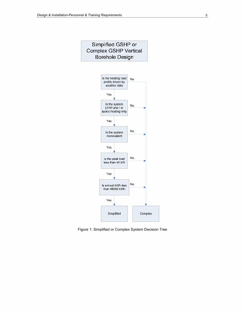
The standards document makes a distinction between a simplified and a complex system in
order to ascertain the requirements of training and qualifications for the different applications
and information requirements etc. Essentially a simplified system is a simple or very small
commercial system less than 45 kWth peak load. The simplified is a simple monovalent or
mono-energetic system whose loads are driven by the weather and control is by a
room/temperature sensor.
A complex system is anything other than the above e.g. heating loads driven by internal gains
and introduction of cooling, controlled by the building management system (BMS) and with
large kW capacity multiple heat pumps.
The vertical borehole ground heat exchanger shall be designed by competent personnel. The
level of required competence would be dictated by the complexity of the project as outlined
above. The decision tree shown in Figure 1 overleaf is to help identify a complex system and
a simplified system.
Design & Installation-Personnel & Training Requirements 5
Figure 1: Simplified or Complex System Decision Tree

Design & Installation-Personnel & Training Requirements 6
Designers of complex systems as identified in Figure 1 shall have one of the following
documented levels of qualification/competence:
• International Ground Source Heat Pump Association (IGSHPA) “Certified Geo-
Exchange Designer (CGD)” status.
see www.igshpa.okstate.edu/directory/directory.asp
or
http://www.aeecenter.org/i4a/pages/index.cfm?pageID=3360
• As US and EU standards regarding qualification are changing rapidly the GSHPA
standard should be put under continuing regular maintenance – as standards often are
– to ensure new developments are rapidly incorporated.
• As there is, at present, no functioning EU or UK accreditation process for vertical
borehole ground heat exchanger design, the term “competent personnel” shall (subject
to later amendment) be deemed to include the following:
- A Chartered Engineer (or EU equivalent qualification), with GSHPA-approved
3rd party documented vertical borehole ground heat exchanger design
experience and who is following a documented Continuing Professional
Development pathway in the field of ground source heating and cooling
- A Chartered Geologist (or EU equivalent qualification), with GSHPA-approved
3rd party documented vertical borehole ground heat exchanger design
experience and who is following a documented Continuing Professional
Development pathway in the field of ground source heating and cooling
- An experienced professional, in the field of engineering, geology, buildings
services or physics, with GSHPA-approved 3rd party documented vertical
borehole ground heat exchanger design experience, who has attended a
GSHPA-recognised programme of training in vertical borehole ground heat
exchanger design e.g. EU GEOTRAINET.
It is recognised that the design of a vertical borehole ground heat exchanger will normally
involve competent personnel with more than one specialism and will typically involve the
involvement of engineering specialists and a geologist.
In the case of simplified installations, as identified in Figure 1, the following are also deemed
to be “Competent Personnel”:
• International Ground Source Heat Pump Association (IGSHPA) “Accredited Installer”
status, www.igshpa.okstate.edu/directory/directory.asp;
• GSPHA-endorsed training which includes simplified system design.
Trained design personnel shall attain sufficient continuing education points in order to
maintain their qualifications in accordance with the certifying body’s requirements. Designers
whose qualifications lapse for any reason shall regain the qualification in accordance with the
certifying body’s requirements before continuing with any design services.
Design & Installation-Personnel & Training Requirements 7
3.2 Ground Loop Fabricators
Ground loop fabricators shall be fully accredited with Butt Fusion Jointing and/or Electro
Fusion of Mains and Services Certificate F/500/6500 (City & Guilds of London) and/or Socket
Fusion Jointing or suitable manufacturer’s training certification. Fabricators must also be
aware of leak risk and that they could be liable if pollution occurs from their defective work1.
Ground loop fabricators shall ensure that they are fully conversant with current practice at least
every five years. Where joint failures occur that are not solely attributable to materials or
equipment failure, all persons responsible for the defective work shall attend retraining prior to
continuation with fabrication duties.
3.3 Drilling Contractors & Drilling Equipment Operators
Drilling Contractors and drilling operatives shall be fully compliant with British Drilling
Association (BDA) Health and Safety manual “Code of Safe Drilling Practice2” and
Environment Agency 2011 “Good Practice Guide1.” as well as understanding their statutory
responsibilities.
All drilling operatives (Lead Drillers and Drillers) employed on the contract shall hold a valid
and current Audit Card of competence applicable to the work and specific drilling operation on
which they are engaged, as issued by the BDA Limited under its BDA Audit or an equivalent
body in a state of the European Union.
All drilling operatives (Lead Drillers and Drillers) employed on the contract shall hold a valid
and current Construction Skills Certification Scheme (CSCS) blue skilled (Land Drilling) card
as issued by Construction Skills Certification Scheme Limited or an equivalent body in a state
of the European Union, and NVQ Land Drilling Level 2.
All drilling rigs employed on the project shall conform to Provision and Use of Work Equipment
Regulations 1998 (PUWER) as amended 2002 Legislation3 Regulation 11, with fully enclosing
interlocked guards to prevent access to rotating parts. Drilling rigs should also be Lifting
Operations and Lifting Equipment Regulation 98 (LOLER)4 certified within the last twelve
months and all lifting accessories tested within the last six months.
Lead Drillers shall be suitably experienced in drilling closed-loop vertical boreholes, loop pipe
installations and borehole grouting. Proof of this is by BDA Audit with geothermal drilling
endorsement.
NOTE: A UKAS (United Kingdom Accreditation Service) certification scheme for organizations
supplying geothermal drilling services is near completion and will become operational in late
2011.
1 Environment Agency 2011. Environmental good practice guide for ground source heating and cooling schemes
2 British Drilling Association, 2002. BDA Health & Safety Manual for Land Drilling : A Code of Safe Drilling Practice
3 Health and Safety Executive, 1998. Provision and Use of Work Equipment Regulations 1998 (PUWER) as
amended 2002 4 Health and Safety Executive, 1998. Lifting Operations and Lifting Equipment regulations 1998 (LOLER)

Design & Installation-Personnel & Training Requirements 8
3.4 Site Supervisor/Manager
Site Supervisors/Managers shall be suitably experienced in the management of ground heat
exchangers (GHEs) and drilling operations or hold a recognised qualification such as:
• International Ground Source Heat Pump Association (IGSHPA) with the “Vertical Loop
Installer” Status, see: www.igshpa.okstate.edu/directory/directory.asp.
The supervisor shall be experienced or knowledgeable in all aspects of the installation they are
supervising which may include drilling, grouting, flow and pressure testing, electro-fusion
techniques, flushing and purging, sterilisation and the addition of thermal transfer fluids. They
must also be aware of their statutory responsibilities and the environmental risks of their
operations with emergency planning if necessary.1 (on previous page)
Design Methods & Compliance
9
4.0 DESIGN METHODS & COMPLIANCE
4.1 General Design Approach
Only suitably trained and competent persons shall carry out the design of a heat pump
system. Reference should be made to Section 3.
4.2 Building Load Data
An accurate assessment of the building’s heating, cooling and hot water requirements shall be
made based upon British European Standard (BS EN) 12831 – 2003, current Chartered
Institution of Building Services Engineers (CIBSE) guidelines as per Simple Heating Design
Guide for 45 kW or under, and CIBSE Guide A for small applications of 45 kWth and under.
MCS Microgeneration Installation Standard MIS 3005, published as Issue 3.0 in 2011,
contains heat loss calculation requirements for applications of 45 kWth and under and shall be
consulted. It refers to monthly and annual average air temperatures for various UK regions as
provided by the MET office and lists these in an appendix.
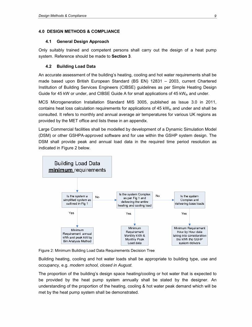
Large Commercial facilities shall be modelled by development of a Dynamic Simulation Model
(DSM) or other GSHPA-approved software and for use within the GSHP system design. The
DSM shall provide peak and annual load data in the required time period resolution as
indicated in Figure 2 below.
Figure 2: Minimum Building Load Data Requirements Decision Tree
Building heating, cooling and hot water loads shall be appropriate to building type, use and
occupancy, e.g. modern school, closed in August.
The proportion of the building’s design space heating/cooling or hot water that is expected to
be provided by the heat pump system annually shall be stated by the designer. An
understanding of the proportion of the heating, cooling & hot water peak demand which will be
met by the heat pump system shall be demonstrated.
Design Methods & Compliance 10
For applications of 45 kWth and under, MCS Microgeneration Installation Standard MIS 3005,
published as Issue 3.0 in 2011, requires that the heat pump will provide at least 100% of the
calculated design space heating power requirement. The Standard shall be consulted for the
details of this. MIS 3005 also goes into detail regarding heat emitters.
4.3 Ground Heat Exchanger Desk Study
A desk study shall be carried out which shall be appropriate for the scale of the ground heat
exchanger to be designed and installed.
The desk study for suitability of a simple vertical borehole installation shall cover as a
minimum:
• Regulatory requirements
• Geology
• Hydrogeology
• Potential contamination of ground and/or groundwater
• Potential for Unexploded Ordnance
• Ground conditions for drilling equipment access
• Underground and overhead services identification and location (including any private
water supply or sewerage system)
• Presence of underground tunnelling, mining and quarrying
• Estimated thermal properties of the ground
• Estimated average undisturbed ground temperature
• Average ambient air temperatures
• Estimated geothermal heat flux
• Available space and access to the drilling location
• Barriers to construction i.e. artesian ground water conditions, running sand or voids for
example etc
• Previous site use and whether contaminated
• Whether Coal Authority permit is required (see 2.4)
• Party wall issues (see 2.8)
A desk study for complex (larger) systems shall contain the above as a minimum, plus:
• Brief impact assessments on the ground e.g. alteration of undisturbed ground temps.
• Brief impact assessment on aquifers alteration of ground water temps, flow,
contamination risk.
Design Methods & Compliance 11
• Brief impact assessment on the surrounding area including other geothermal schemes,
water abstraction schemes or other environmental receptors such as springs,
wetlands, lakes and rivers.
• Assessment of the sustainability of the scheme based on annual kWh and peak loads
for heating and cooling.
• Brief impact assessment of the surrounding area including other geothermal schemes
or water abstraction scheme.
BS5930: 1999 + A2:2010 gives guidance for desk studies1.
Where the desk study includes any outline design works the specialist shall clearly state what
assumptions have been made and which particular elements of the design have been
covered.
4.4 Ground Heat Exchanger Design
The design of the ground heat exchanger shall be in compliance with the heat pump
manufacturer’s specification and operating parameters of the heat pump and shall be clearly
documented so that such compliance may be demonstrated.
The design of a simple ground source heat exchanger system for small applications of 45 kWth
and under shall be undertaken in accordance with MCS Microgeneration Installation Standard
MIS 3005, published as Issue 3.0 in 2011. Importantly, this Standard sets a requirement that
the “temperature of the thermal transfer fluid entering the heat pump shall be designed to be
>00C at all times for 20 years”.
Detailed ground heat exchanger design incorporates the borehole design, spacing, grout
requirements, header pipe work design, trench requirements and backfill, header valve
chambers or valve vaults up to the building interface.
The scope can be further extended to include the building penetration, internal piping,
pressurisation requirements, monitoring and Building Management Systems (BMS),
monitoring requirements and circulation pump sizing. The specific standards relating to such
an extension of the scope of design are not covered by this document and further guidance as
required, shall be sought.
In cases where a competent specialist is either (a) providing a provisional or preliminary
design, before all relevant building constraints have been identified or (b) providing a specific
input to a complete ground heat exchanger design process, the specialist should clearly
identify which elements of the design are covered and any assumptions that have been made
by the specialist regarding other elements of the overall design.
The design of the ground heat exchanger system shall take into consideration; heat pump
performance including minimum coefficient of performance (COP) requirements and
estimated seasonal performance factor (SPF), fluid temperature constraints, geology, the
thermal conductivity of the ground, flow rate, loop configuration and its hydraulic implications,
1 British Standards Institution, 1999/2010. The code of practice for site investigations
Design Methods & Compliance 12
local climate and landscaping. If thermal conductivity data is not available then appropriate in
situ thermal response testing (TRT) shall be performed by a competent company. Borehole
Thermal Resistance is also one of the design parameters that must be taken into
consideration.
Data obtained during the desk study and/or TRT shall be used with appropriate design
software for ground heat exchanger sizing. For larger and more complex heating and cooling
systems, more sophisticated ground models shall be used to prove the heat exchanger
system design is viable in the longer term.
Building load information including annual kWth and peak load shall be used for simple ground
heat exchanger design as outlined in Figure 1.
For complex systems, the minimum requirements are for a monthly profile of kWth of heating
and cooling along with peak load for each month and the maximum duration of the peak load
per month. Where possible however, hourly kWth and peak load information should be used.
Where the ground heat exchanger will be providing a base load for a complex system with
additional plant delivering the additional load, an hour by hour load profile shall be used in
order to identify the annual kWth the ground heat exchanger will absorb or deliver. The
required load data is outlined in section 4.2 above.
The design of a system shall take into account specific ground conditions that may affect the
integrity or performance of the heat exchanger. The Environment Agency should be contacted
if a scheme is to be installed in land affected by contamination and care shall be taken not to
compromise ground contamination remediation measures (e.g. capping layers). Backfilling
shall be carried out to ensure no pathways for the migration of groundwater or ground
contamination are created. The Environment Agency shall if necessary be consulted for
guidance relating to the risk assessment procedure appropriate to the system being designed.
Refer to the checklists in EA, 20111 to determine environmental risks from your proposed
design. Steps must also be taken to ensure prevention of the migration of gases (e.g. radon or
methane) into a building. Early consultation is advised.
4.5 Results of System Design Calculation
Results of system design calculation shall be reported to the client outlining the anticipated
sustainability and design life of the system. Commercially available software programmes
shall be used for complex designs and details of how the software output is calculated should
be available from the software distributor.
1 Environment Agency 2011. Environmental good practice guide for ground source heating and cooling schemes
Thermal Response Testing
13
5.0 THERMAL RESPONSE TESTING
5.1 In Situ Formation Thermal Response Testing
Two sources of information which should be referred to for in situ TRT methodologies include
the American Society of Heating, Refrigerating and Air-Conditioning Engineers (ASHRAE1)
and Sanner2. The following bullet points summarise the key features of the aims of the test,
borehole and equipment requirements and test methods provided by these references.
NOTE: A European EN Standard is under development for thermal response testing.
5.1.1 Aim of the Test
In situ formation thermal response testing (TRT) should be conducted when knowledge of
ground conditions is poor. For example, the thermal conductivity of the ground or more
complicated effects of groundwater flow upon borehole exchange rates may need to be
established. The number of TRTs shall be appropriate to the size of the installation, taking into
consideration the variability of the geological and hydrogeological conditions as determined in
the desk study.
5.1.2 Key determinants of the Test
• Average Undisturbed Formation Temperature
• Thermal Conductivity
• Volumetric Heat Capacity
• Thermal Diffusivity
5.1.3 Test Equipment & Borehole Requirements:
• The borehole log shall be made available for calculation of some parameters. The
borehole should be logged in accordance with BS EN ISO 14688-13 and BS EN ISO
14689-14. As a minimum, samples shall be taken at 1m intervals and a representative
descriptive log provided by a geologist based upon the samples taken.
• It is recommended that the grout thermal conductivity should be equal to or greater
than 1.30 W/mK in order to overcome the borehole resistance early in the test. The
minimum test duration as calculated below shall be extended where grouts with lower
thermal conductivity values are used.
• Boreholes to be tested shall have their u-bend ground loop filled with potable water at
time of insertion of the loop. If any doubt exists as to the quality of water in the loop, a
biocide clean shall be used prior to the test.
1 ASHRAE, 2007. Heating, ventilating and air-conditioning application. Chapter 32. Geothermal Energy.
2 Sanner et al, 2005. Thermal response test – current status and worldwide application. Proceedings World
Geothermal Congress 2005, 24-29, April 2005, Antalya, Turkey. 3 British Standards Institution 2002. Geotechnical investigation and testing -- Identification and classification of soil -
Part 1: Identification and description 4 British Standards Institution 2003. Geotechnical investigation and testing. Identification and classification of rock.
Identification and description

Design Methods & Compliance 14
• The test borehole shall be fully grouted.
• The grout material shall be brought completely to surface prior to the waiting period.
• The borehole diameter shall be no larger than 200mm.
• The distance between the thermal response test unit and the borehole shall be as
short as possible and no longer than 1.5m in general.
• The pipes shall be heavily and separately insulated to minimise the influence of
ambient conditions on the test. Where significant insulation is occurring, reflective
material should also be used to minimise absorption of solar radiation.
• The test unit shall also be insulated to minimise the influence of ambient conditions on
the test.
• The test unit shall be capable of delivering and monitoring power with the standard
deviation of the power less than ±1.5% of the average value, with peaks less than
±10% of the average, OR; have a maximum return temperature variation of ±0.3°C
from a straight line trend of a log (time) versus average loop temperature.
• The fluid temperature shall be measurable to an accuracy of <0.3°C, the power input
measurable to an accuracy of <2%, and the fluid flow rate measurable to <5%
accuracy.
• The heat rate supplied to the u-bend loop shall be 40 – 80 W per metre of borehole,
with lower rates corresponding to lower thermal conductivity formations.
• Flow rates shall be sufficient enough to provide a differential loop temperature of 3.7 -
7.0°C.The flow shall be turbulent.
• Ambient air temperatures shall be measured for the duration of the test so that
interference effects can be detected.
• Test boreholes should be as similar to the intended design and depth as the borehole
field.
5.1.4 Test Procedure
• The minimum duration of the test shall be estimated by calculation based upon
anticipated properties of the heat exchanger. The minimum time, t1, until data is
suitable for determination of the thermal properties shall be calculated using the
following formula:
Where t1 = minimum time until determination can begin (s) Where ro = borehole radius (m) Where α is derived from the following formula:
α
2
0
1
5rt =
p
est
cρ
λα =
Design Methods & Compliance 15
Where λest = estimated thermal conductivity (W/mK)
Where ρcp = volume related thermal capacity (J/m3/K)
At least 36 hours measuring duration shall remain after the estimated period to overcome the
borehole resistance as calculated above. Where grouts with less than 1.30 W/mK are used,
the period required to overcome the borehole resistance test shall be extended accordingly.
• There shall be a waiting period of at least 5 days for low thermal conductivity soils and
rocks (k < 1.70 W/(mK)) after the ground loop has been installed and grouted, before
the thermal conductivity test is initiated. There shall be a delay of 3 days for higher
thermal conductivity formations (k > 1.70 W/(mK)) after the ground loop has been
installed and grouted, before the thermal conductivity test is initiated.
• Delays of longer than 5 days can be required where air flush drilling has been carried
out as this introduces hot air into the formation, or where cementatious grouts are
used, since the setting of cement is an exothermic reaction. If doubt exists the
borehole shall be monitored until such time as equilibrium is reached prior to starting
the test.
• A manual undisturbed formation temperature measurement shall be made at the end
of the waiting period by direct insertion of a probe inside a water-filled ground heat
exchanger at a minimum of 5m intervals, to enable the average undisturbed
temperature for the borehole length to be calculated.
• The thermal response test shall be initiated without heating elements switched on. The
temperature measurement as the liquid exits the loop, immediately after start-up and
for up to 30 minutes thereafter depending on the flow rate and the volume of the
ground loop, shall be logged.
• Testing shall comprise the application of controlled heat to the closed-loop for the
duration of the test. Specific requirements for the monitoring and provision of heat and
power to the circulated fluid are that:
- The collected data shall be analysed using the line source method. Other
methods, such as the cylindrical heat source method or using a numerical
algorithm may be considered.
- If the borehole needs to be re-tested, at least 10-14 days shall have passed
from the end of the previous test, or the u-bend loop temperature will have
naturally returned to within 0.28°C of the natural average undisturbed
temperature of the borehole at the commencement of the test.
- The results of the test shall be analysed by personnel fully conversant and
trained in the line source analysis method with suitable qualifications such as
those listed in 3.1.
- If the test is interrupted during the heating period, a re-stabilisation period of at
least 10-14 days shall be allowed before a further test is conducted.

Ground Heat Exchanger Materials
16
6.0 GROUND HEAT EXCHANGER MATERIALS
Due to the nature of a vertical borehole installation e.g. lack of access and long design life, a
very high level of quality and durability of all ground heat exchanger components shall be
required. Section 6 is purely related to the material specification and manufacturer testing
requirements and does not relate to the testing requirements for the materials once installed in
the ground.
6.1 Pipe Materials & Tolerances
Each loop shall have sufficient markings on the pipe to identify the material, dimensional
properties, supplier’s name and production period codes.
The acceptable pipe material for the ground heat exchanger shall have a slow crack growth
resistance, at a pressure of 9.2bar and temperature of 80°C, of greater than 500 hours, e.g.
PE100+, PE100RC etc. The manufacturer shall warrant that the pipe is extruded from
verifiable virgin grade raw material from a certified producer of PE pipe materials which meet
the enhanced technical requirements of the PE100+ Association. The resins which fall under
the nomenclature of PE100+ can be found at:
http://www.pe100plus.com/index.php/en/content/index/id/39
Pipe shall be manufactured to outside diameters, wall thickness and respective tolerance as
specified in BS EN 122011 part 2.
6.2 Electro-Fusion Fittings: Materials & Tolerances
The acceptable material for the ground heat exchanger fittings is black PE100 High Density
Polyethylene. The manufacturer shall warrant that the fittings are made from verifiable virgin
grade raw material.
Electro-fusion fittings shall be manufactured to dimensional tolerances as specified in BS EN
122011.
6.3 Butt-Fusion Fittings Materials: & Tolerances
The acceptable material for ground heat exchanger fittings is black PE100 High Density
Polyethylene. The manufacturer shall warrant that the fittings are made from verifiable virgin
grade raw material.
Butt-fusion fittings shall be manufactured to dimensional tolerances as specified in BS EN
122011.
6.4 Socket-Fusion Fittings: Materials & Tolerances
The acceptable material for the ground heat exchanger fittings is black PE100 High Density
Polyethylene. The manufacturer shall warrant that the pipe is extruded from verifiable virgin
grade raw material.
1 British Standards, 2003. Plastic piping systems for water supply. Polyethylene (PE). Fitness for purpose of the
system (BS EN 12201)

Ground Heat Exchanger Materials 17
Socket-fusion fittings shall be manufactured to dimensional tolerances as specified in BS EN
122011 (on previous page).
6.5 Specific Pipe Application & Dimensional Specification
All fittings and pipe shall have specified pressure ratings including any assembly of individual
components used to manufacture a sub-assembly for a ground heat exchanger.
External pipe diameters between 20mm and up to 90mm and any pipe diameter utilised as a
vertical borehole heat exchanger shall be manufactured with minimum pressure rating of 16
bar with SDR of 11.
External Pipe diameters larger than 90mm shall be manufactured with minimum pressure
rating of 10 bar (SDR 17) unless used in a vertical borehole which shall then be 16 bar with
standard dimension ratio (SDR) of 11.
6.6 Off Site Factory Manufacture & Quality Control
Vertical borehole u-bend loops shall be factory manufactured under controlled and quality
assured conditions. The loop shall be manufactured from pipe conforming in every way with
these standards and shall have a purpose-manufactured u-bend fusion-welded to each leg of
the pipe. The maximum number of welds to form the u-bend shall be two welds, where each
pipe is attached to the u-bend.
Each loop shall be hydraulically pressure tested by the loop manufacturer in accordance with
The Pressure Equipment Regulations 19991 and at 150% of the minimum pipe design
pressure.
Each loop shall have metre marks identifying the length of the loop commencing with zero at
the u-bend in order to verify the installed depth from surface.
The manufacturer/supplier shall warrant that all ground loops are manufactured in compliance
with the above standards.
6.7 Pipe & Fittings Sizing
Pipe and fittings shall be sized in order to maintain efficient heat transfer in the ground heat
exchanger.
Borehole u-bend loops shall be sized to ensure turbulent flow with a minimum Reynolds
number of 2,300 at peak load (coldest fluid temperature) and design flow rate conditions.
The fluid properties of the system such as antifreeze requirements etc and minimum system
fluid temperatures shall be taken into consideration when determining the Reynolds number.
The borehole and header system shall be designed to ensure that pumping power
requirements are kept to a minimum when included with the indoor pipe work and heat pump
head loss. System pump power requirements should be 1.25% of the heat pump capacity. For
example, a 100 kW heat pump capacity should have a pump requirement of 1.25 kW.
1 Legislation.gov.uk 1999. The Pressure Equipment Regulations

Ground Heat Exchanger Materials 18
Pipe work shall be dimensioned so as to ensure that flushing and purging requirements can
be met and large loop fields shall be arranged in multiple headers to ensure that the system
can be flushed efficiently and in accordance with section 10.2.
Pipe Jointing, Methods & Materials
19
7.0 PIPE JOINTING, METHODS & MATERIALS
7.1 Fusion Processes
All underground piping shall be joined with heat fusion where the fusion fitting and pipe form a
homogenous pipe assembly. Acceptable methods of fusion are electro-fusion, butt fusion and
socket fusion. Fusion processes shall be carried out strictly in accordance with the
manufacturer’s instruction and procedures and by suitably trained personnel as outlined in
section 3.2.
7.2 Transition Fittings
Transition fittings shall be used to adapt to copper or threaded pipe work above ground or in
easily accessible locations only. Acceptable transition fittings include flange; threaded;
victaulic; barbed and clamped.
7.3 Leak Free Installation
The system shall be installed as a leak-free installation and for the design life of the
installation, which would generally be a minimum of 50 years.
7.4 Mechanical Connections
All mechanical and compression connections shall be accessible for future maintenance,
removal and replacement.
Ground Heat Exchanger Grout
20
8.0 GROUND HEAT EXCHANGER GROUT
8.1 General
Grout thermal conductivity is an important aspect of ground heat exchanger design. The
designer shall be responsible for selection of the grout to support the foundation of the ground
heat exchanger design. The following standards relate to the materials and methods of testing
and verification of properties, as supplied by the manufacturers.
8.2 Grout Thermal Conductivity
Grout material thermal conductivity shall be determined by the following tests or comparable
to EU standards:
• Pliable materials – American Society for Testing and Materials (ASTM) D-5334
“Standard test method for determination of thermal conductivity of soils and soft rocks
by thermal needle probe procedure”
• Rigid materials – ASTM C-177 “Standard test method for steady heat flux
measurements and thermal transmission properties by means of the guarded hot plate
apparatus”
Materials that are bentonite-based are classified as pliable materials and cement based
products or grout mixtures containing cement that cause the product to become rigid once
cured are classified as rigid materials.
8.3 Grout Hydraulic Conductivity (Permeability)
The hydraulic conductivity of the grouting material shall be determined using ASTM D-5084
“Measurement of hydraulic conductivity of saturated porous materials using a flexible wall
permeameter”.
The maximum allowable hydraulic conductivity of grout value shall be 1x10⁻⁹ m/sec or lower if
required by specific local regulation or requirement.
Where cementatious grouts are used, the maximum allowable permeability of the combined
grout material, borehole and installed loop pipe shall be no higher than the surrounding
ground. Consideration should be given to the contraction of the pipe away from rigid materials
under operational conditions which may significantly increase the permeability of the
installation to unacceptable levels.
Consideration should also be given to the operational temperature range of the grouts and the
hydraulic conductivity shall not be impaired by shrinkage or freeze thaw cycles.
Pathways for contaminants into groundwater, and pathways for hazardous gases e.g. from
mine workings and unworked coal shall not be created through shrinkage of grout away from
borehole walls.
Ground Heat Exchanger Materials 21
8.4 Manufacturer / Supplier validation of properties
Validation of thermal conductivity and hydraulic conductivity properties as per 8.2 and 8.3
shall be carried out on manufacturer’s products by an independent, United Kingdom
Accreditation Service (UKAS) accredited laboratory or European equivalent in order to
validate compliance with these standards as per 8.2 & 8.3 above.
Thermal conductivity values shall be determined and verified using the manufacturer’s mixing
instructions and manufacturer-specified additives and materials.
The test shall be carried out annually and a certificate produced at each test. Copies of
certificates shall be made available when requested by the installer and the sales literature
shall outline the date of the test certificate and the renewal date.
Pipe Placement & Backfilling
22
9.0 PIPE PLACEMENT & BACKFILLING
9.1 Piping Material Delivery to Site and Storage
All pipes shall be delivered suitably wrapped from the manufacturer and fitted with protective
caps to prevent debris from entering the pipe work on site. The caps shall only be removed
when the pipe is to be connected to the system.
Pipes shall be brought to site and unloaded and stored using correct handling equipment.
Pipes shall not be dropped, dragged or mishandled on site and accidental damage during
delivery and handling shall be avoided.
Pipes shall be stored in dry areas of the site that are not subject to build up of rain water in
puddles or creation of muddy surfaces. The pipe work shall be stored in a manner so as not to
damage the ends of the pipe or the main body of the pipe. They shall be stored in areas that
are not prone to other heavy site traffic etc that may cause accidental damage to the pipes.
Ground loops shall be stored on pallets to ensure they are not directly in contact with the
ground and the possible sharp stones that may exist at the surface. Straight pipes shall be
supported sufficiently based on their diameter to ensure that no part of the pipe comes into
contact with the ground where sharp stones or objects may be lying. The number of supports
will depend on the diameter and SDR of the pipe in question.
Pipes should also be stored in a manner that prevents contamination with substances at the
surface; e.g. oils etc, which could cause environmental risks to groundwater and the integrity
of the piping product.
9.2 Header Piping Systems
Where horizontal header pipes are laid into a trench and bends are formed, the bend shall be
no tighter than 25 times the pipe diameter. For example, the minimum bend diameter for
40mm pipe shall be 1000mm. Care must be taken to ensure that pipes do not ‘kink’ around
corners and, where required, elbow fittings will be used to prevent kinking.
Prior to backfilling, the trench bottom shall be inspected to ensure that no sharp objects are
present.
Backfill material shall be inspected prior to re-installation to ensure the suitability of the backfill
and ensure that no sharp objects or rocks exist in the backfill.
Where excavated material is not suitable for backfilling, sand shall be placed in the trench
bottom, around and above the pipe work.
Water Industry Specification for Bedding and Sidefill Materials for Buried Pipelines (WIS 4-08-
02)1, which outlines suitable backfill procedures, shall be consulted if any doubt exists.
Any ground heat exchanger pipe passing within 1.5m of a wall, structure, drainage pipe,
private drainage system (septic tank, package treatment plant or cesspit) or water pipe shall
1 Water Industry Standards 1994. Specification for Bedding and Sidefill Materials for Buried Pipelines
Pipe Placement & Backfilling 23
be insulated with non-compressive insulation suitable for operation at all temperatures and
conditions experienced by the ground heat exchanger system.
Warning tape shall be laid directly above all horizontal header pipes. The warning tape shall
clearly identify that they protect “Geothermal Pipes Below”. Ideally, this tape should be
detectable to prevent pipework being damaged by any future works.
Header pipe minimum depth of placement should generally be 1000mm to avoid other
services where possible and in systems without antifreeze, to avoid frost damage to ground
heat exchangers.
Where feed and return pipe work is within the same trench, a minimum of 500mm between
feed and return pipe shall be maintained, either vertically or laterally. Where the minimum
distance cannot be maintained over long pipe runs, insulation shall be used either over the
pipes or with the use of insulation materials between pipes.
The ground array shall be purged of air on completion of the installation and again during
commissioning as per section 10.2.
9.3 Ground Heat Exchanger Loop Protection
The loop shall be installed via a loop installation reeler, either powered, manual or similar, in
order to avoid the possibility of damage and contamination to the loop pipe on the site prior to
its installation. The uppermost edge of the borehole or surface casings shall be covered with a
smooth edging to prevent chaffing or damage to the loop pipe during installation.
The loop shall be filled with clean potable water prior to or during installation and sufficient
weights shall be added to aid in the installation through any drilling fluids providing support to
the borehole walls. During installation the loop shall also pass over a wellhead roller or similar
device in order to prevent chaffing or damage to the loop pipe from sharp surface casing
edges, etc. The casing upper surface shall be fitted with a suitable smooth surface to further
avoid any damage to the loop pipe. As the loop is lowered into the borehole, a visual
inspection of the loop pipe shall be made for surface damage. A maximum tolerance of 10%
of the wall thickness for scratches on the surface shall be acceptable for installation.
Loop weights shall not have sharp or raised edges, which may be placed in close contact with
the loop pipe and cause damage during the design lifetime of the loop installation of minimum
50 years. The weights shall have a tapered leading edge to aid in the installation of the loop
assembly.
Once loops are installed into the borehole, the caps shall be securely fitted again and the
borehole protected in order to maintain the integrity of the loop until such time as the loop has
been flow and pressure tested. On completion of the flow and pressure test, caps shall be
fused onto the loops to provide protection from material entering the loops prior to connection
to the header system.

Pipe Placement & Backfilling 24
9.4 Ground Heat Exchanger Installation
Vertical boreholes shall have sufficient minimum diameter throughout all portions of the
borehole to accommodate the design sized loop pipe or multiple loops, provide the anticipated
spacing in the design and the installation of a tremie pipe of suitable size to allow the design
grout to be placed.
Once installed at the desired depth, the loop pipe shall be gently but securely clamped in
place to prevent displacement during grouting. The clamps shall remain in place until the grout
has set sufficiently.
The borehole shall be grouted from bottom to top with a suitable recognised geothermal
grouting material and tremie pipe as outlined in section 8.
Consideration shall be given to the differential densities of the grout material and the water-
filled loop pipe, and the relevant installation depth (in particular for installations beyond 150m)
to avoid collapse of the ground loop.
Other methods of backfill may be considered subject to the following:
Granular materials shall be installed via a tremmie pipe to ensure accurate placement of the
very high hydraulic conductivity backfill medium. The backfill material shall be placed into the
target zone by insertion of the tremie pipe to the base of the target zone and gradually
removing the pipe as backfilling proceeds. At no point shall the tremie rise more than 3m
above the level of backfill in the borehole.
Where granular material is considered, there shall be a means of placing grout as per section
8 in any section of the borehole that requires isolation to avoid cross contamination of aquifers
or contamination pathways being created from surface.
Where more than one aquifer may be penetrated, these shall be grout sealed to prevent
upward or downward flow from one aquifer to another.
Where sub-artesian or full artesian conditions may occur, the grout shall seal the borehole to
prevent break out at the surface or upward or downward flow from one aquifer to another.
Where a ground heat exchanger loop is completed as a u-tube hanging in an open water well,
a securely grouted length of plain casing shall be installed in its upper section to a minimum
depth of 15m or to encounter competent bedrock, whichever is the greater depth. The casing
shall be centralised and positioned within an upper open borehole section that is 50% greater
in diameter than the nominal casing diameter being installed. For example, where a 150mm
nominal bore (NB) casing is being installed the drilled hole diameter for installation of the
casing shall be a minimum of 225mm diameter to provide suitable grout annulus. The casing
being installed shall be centralised. The borehole shall be constructed as outlined above and
in accordance with Environment Agency SCHO1000BFHB-BP, Water Supply Borehole
Construction and Headworks: Guide to Good Practice1.
1 Environment Agency 2011. Environmental good practice guide for ground source heating and cooling schemes

Pipe Placement & Backfilling 25
When considering an open water well closed-loop installation, specialist guidance shall be
sought from a hydrogeologist in order to ensure the installation is suitable for the geological
and hydrogeological conditions to be encountered.

Flush, Purge & Pressure Test of Ground Heat Exchanger
26
10.0 FLUSH, PURGE & PRESSURE TEST OF GROUND HEAT EXCHANGER
10.1 Quality Control
Each loop shall be delivered to site with quality control certificates from the manufacturer
stating details of an individual hydraulic pressure test.
Where completed sub-assemblies, such as valve vaults and manifolds are delivered to site,
these shall be accompanied with a pressure test certificate from the manufacturer.
During installation of the loop, a visual inspection of the pipe shall be made as the loop is
inserted into the borehole for visible signs of pipe wall damage. A maximum indentation or
scratch of 10% of the pipe wall thickness shall be allowable and any indentation or scratch in
excess of 10% of the pipe wall thickness shall not be installed.
10.2 Purging the System
On completion of the ground heat exchanger or at stages throughout the installation of larger
ground heat exchangers the system shall be flushed in order to remove debris and air. The
flushing equipment shall be capable of delivering a sufficient flow rate and head pressure to
achieve a minimum of 0.61 m/s velocity in any pipe diameter in the system.
The flushing pump system shall be capable of reversing the flow without removal of hoses,
monitoring the delivery and return pressure, monitoring the flow rate being delivered, have
means of inspecting the fluid with a sight glass and shall be capable of filtering debris from the
system. All values shall be recorded for the system Operations & Maintenance (O & M)
Manual.
Visual inspections of the return flow through a sight glass shall be carried out and once the
return is free from visible air bubbles the flushing at the minimum of 0.61 m/sec shall be
maintained for a minimum of 15 minutes, or longer for larger ground heat exchangers.
10.3 On-site Pressure Testing
Each loop shall be pressure tested following insertion into the borehole to ensure that no
damage has occurred during the installation.
All horizontal header components of the ground heat exchanger shall be pressure tested prior
to backfilling, where possible. As a minimum, all joints shall remain accessible until such time
as a pressure test has been completed.
Where the possibility exists that loop pipes or horizontal headers may have become damaged,
a pressure test shall be carried out prior to installation.
10.4 Pressure Test Procedure for In Situ Loops
The test pressure for the loop shall be determined based upon the density of the grout placed
and the depth of the installed loop.
Flush, Purge & Pressure Test of Ground Heat Exchanger 27
The test procedure shall be in accordance with BS EN 805 section 11.3.3.4 which allows a
modified test to be carried out for Polyethylene pipes. The modified test shall be in
accordance with WRc “A Guide to the Testing of Water Supply Pipelines and Sewer Rising
Mains” 1st Edition, June 1999, Section 5, available from:
http://www.wrcplc.co.uk/default.aspx?item=339
Or BS EN 805 Annex 27, available from: http://www.bsigroup.com/en/Standards-and-
Publications
The ground array shall be fully purged of air prior to the test commencing. The ambient
temperature shall also be monitored during the test and notes shall be taken as to whether the
pipe line is exposed to direct sunlight or other conditions which may affect the results of the
test.
The tests involve pre-loading periods and main test periods. The fluid volume added to the
test section shall be monitored accurately and the pressures and time shall be accurately
monitored. The testing equipment shall be capable of an automated addition of water to
ensure accuracy and exact duplication of each test. The test pressures shall be attained as
uniformly as possible, by a steady linear increase in pressure.
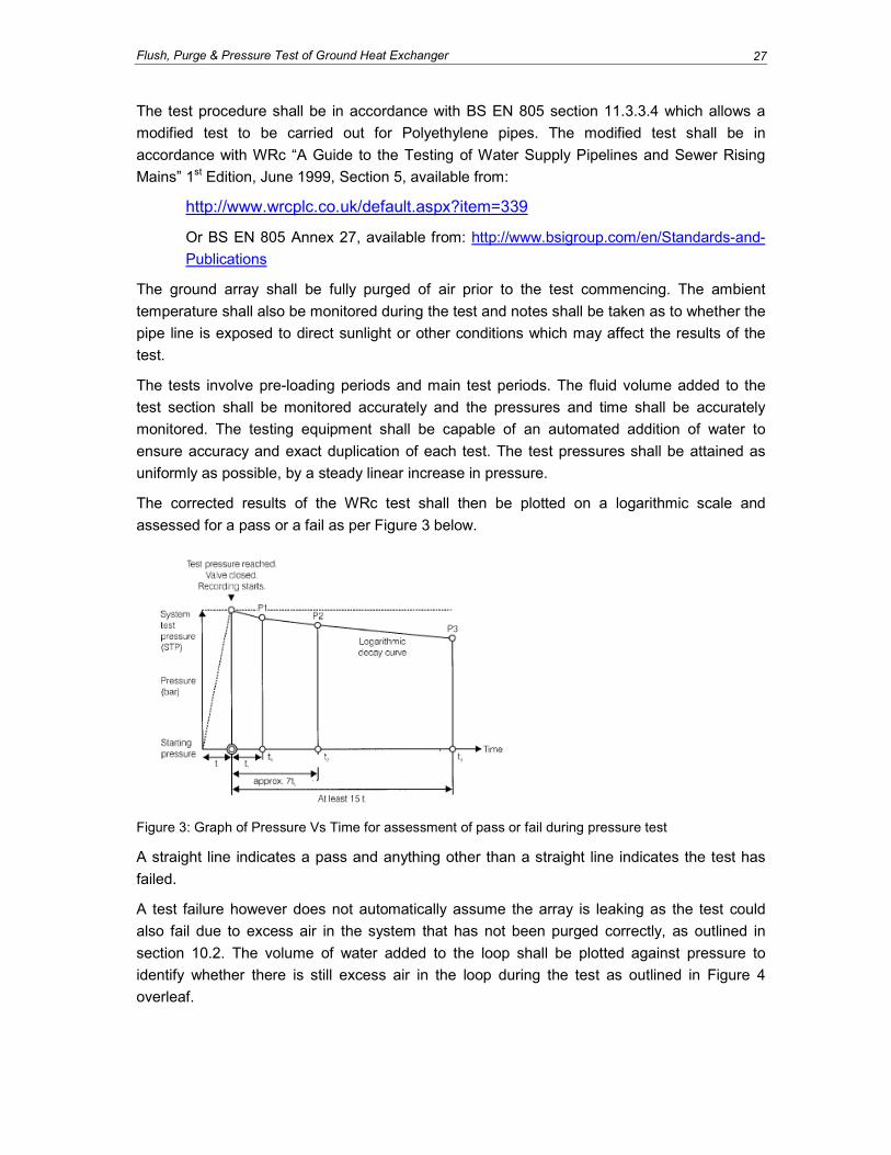
The corrected results of the WRc test shall then be plotted on a logarithmic scale and
assessed for a pass or a fail as per Figure 3 below.
Figure 3: Graph of Pressure Vs Time for assessment of pass or fail during pressure test
A straight line indicates a pass and anything other than a straight line indicates the test has
failed.
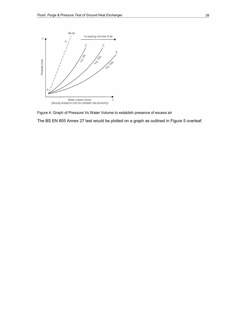
A test failure however does not automatically assume the array is leaking as the test could
also fail due to excess air in the system that has not been purged correctly, as outlined in
section 10.2. The volume of water added to the loop shall be plotted against pressure to
identify whether there is still excess air in the loop during the test as outlined in Figure 4
overleaf.
Flush, Purge & Pressure Test of Ground Heat Exchanger 28
Figure 4: Graph of Pressure Vs Water Volume to establish presence of excess air
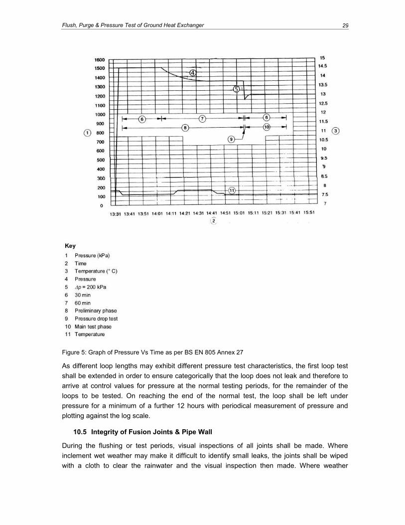
The BS EN 805 Annex 27 test would be plotted on a graph as outlined in Figure 5 overleaf.
Flush, Purge & Pressure Test of Ground Heat Exchanger 29
Figure 5: Graph of Pressure Vs Time as per BS EN 805 Annex 27
As different loop lengths may exhibit different pressure test characteristics, the first loop test
shall be extended in order to ensure categorically that the loop does not leak and therefore to
arrive at control values for pressure at the normal testing periods, for the remainder of the
loops to be tested. On reaching the end of the normal test, the loop shall be left under
pressure for a minimum of a further 12 hours with periodical measurement of pressure and
plotting against the log scale.
10.5 Integrity of Fusion Joints & Pipe Wall
During the flushing or test periods, visual inspections of all joints shall be made. Where
inclement wet weather may make it difficult to identify small leaks, the joints shall be wiped
with a cloth to clear the rainwater and the visual inspection then made. Where weather
Flush, Purge & Pressure Test of Ground Heat Exchanger 30
conditions make it impossible to visually inspect the joints, on completion of the test, the
system shall be left under pressure for a minimum of 24 hours.
10.6 Flow Testing of Loops
Each loop shall be flow tested in both directions following insertion into the borehole with
mains potable water. A minimum of 3 flow rates and head loss measurements shall be taken
on the installed borehole at rates in excess of the design system flow rate but not sufficiently
high to over pressure the loop. The measured values shall be compared to design calculated
values at the same flow rates to ensure that there is no blockage or kinking of any pipe. Once
tested for flow and pressure, the loop shall be evacuated of water to a minimum 1m below
ground level (BGL) and shall be heat-fused to seal the loop from debris ingress.
Head loss measurements shall be determined by using a pressure measuring device directly
on the feed and return leg of the loop at the top of the borehole and the differential pressure
between the two values shall represent the loop head loss.
10.7 Heat Exchanger Flow Testing
The ground heat exchanger shall be flow tested either in its entirety or in sections depending
on the size of the ground heat exchanger. Pressure drop for the system section being tested
shall be compared to design calculated values. A minimum of 3 flow rate and head loss
measurements shall be taken at flow rates in excess of the system design flow rate for the
section under test. The measured values shall be compared to design calculated values at the
same flow rates to ensure that there is no blockage or kinking of any pipe.
Head loss measurements shall be determined by using a pressure measuring device directly
on the feed and return leg of the system being flushed. The differential pressure between the
two values shall represent the test section head loss.

Indoor Piping & Valve Vaults
31
11.0 INDOOR PIPING & VALVE VAULTS
11.1 Circulator Sizing and System Components
The circulating pump shall be selected such that it will be capable of delivering the heat pump
manufacturer’s minimum flow rate under all operating conditions.
Where heat pumps are installed with integral circulating pumps the ground heat exchanger
shall be designed in order to be fully compatible with the flow rate and developed head of the
integral circulating pump.
The circulating fluid properties such as addition of antifreeze and minimum operational
temperatures shall be considered when sizing the circulating pump.
Debris and air shall have been removed by flushing prior to starting the circulating system.
Prior to start up, the loop shall be pressurised in accordance with manufacturer’s
recommendations:
• For example to 1.4 – 2.0 bar in summer cooling periods with circulating water between
20°C – 30°C, and;
• 2.75 – 3.5 bar in winter heating conditions where the water is circulated at 5°C or
lower.
Where pressurisation units are installed, the sizing of such units shall take into consideration
the fluid thermal properties, the pipe component thermal properties, maximum and minimum
pressure requirements for the pump and system. Any make-up fluid for automated topping up
of the system shall be stored in containers sealed against contamination and contain a biocide
to ensure no system contamination occurs during dosing. Where mains connected auto-fill
units are installed, the operation of such units shall be linked to the BMS as a “fault alarm” and
be fitted with a double check valve.
Circulating pumps that include volute design and which meet manufacturers’ requirements are
excluded from the requirements of pressurisation.
The circulation system shall have, within 500mm of the heat pump system, the ability to test
flow and pressure in order to test the performance of the ground source side of the heat
pump. The capability may be integral to the heat pump and directly linked to the heat pump
management system, or easily accessible manual binder points.
11.2 Valve Vault & Indoor Piping Requirements
Loop flushing and charging valves shall be sufficiently plugged and/or be equipped with
removable handles to ensure that no accidental leakage of loop fluid can occur.
Boiler-type service valves shall not be used.
Transition fittings between differing materials shall be easily accessible.
All indoor piping where condensation may form shall be fully insulated in accordance with
chilled water pipework insulation requirements.

Thermal Transfer Fluid Requirements 32
Any above ground exterior piping shall be fully insulated with exterior grade non-compressive
insulation with suitable UV resistance.
Where pipes pass through walls or structures, they shall be sleeved and the annulus between
the pipe and sleeve fully sealed with non-hardening sealing compound or components and/or
insulation as required.
Where pipes are within 450mm of the surface and the system is antifreeze free, they shall be
insulated with materials suitable for underground application and be non-compressive.
Where threaded connections are used, good quality clean threads shall be used with specific
sealants taking into consideration the antifreeze being used, if any.
Valve chambers and vaults shall be designed so as to provide the minimum additional head
loss in the systems. In particular, valves shall be full flow valves and all pipework to and from
the valve manifolds shall be designed for the flow rates experienced in each part of the
manifold.
Pressure and temperature ports shall be installed on each inlet and outlet of the manifolds.
Underground chambers requiring personnel access shall be designed to minimise risk to
personnel, including a means of ventilating the chamber prior to personnel entry and ensuring
that all safety notices and warnings are clearly displayed. The valve vaults shall be fully
sealed and free from any leaks of groundwater into the chamber. The structural stability of the
chamber shall be considered when deciding the type of housing.
Thermal Transfer Fluid Requirements
33
12.0 THERMAL TRANSFER FLUID REQUIREMENTS
12.1 Thermal Transfer Fluid Selection, Use & COSHH Requirements
Thermal transfer fluid refers to the secondary or ‘loop’ fluid permanently installed in the ground
array. The fluid will include components of antifreeze, biocide and corrosion and scale
inhibitors.
The thermal transfer fluid material shall be compatible with all components within the closed-
loop system including all pipework, valves, pumps, heat exchangers, expansion vessels and
heat pumps. If in doubt, the installer/designer shall provide details of the fluid to be used to all
component manufacturers whose products are intended for use in the system for verification
of compatibility with their products. Compatibility data for system materials shall be made
available on request.
The specifier/designer, supplier and installer shall all be aware of the Control of Substances
Hazardous to Health (COSHH) regulations1 and shall comply with these regulations where
applicable. The designer and installer shall make their own selection of fluid and shall ensure
that operatives are fully aware of all safety requirements for the use of the fluid and be familiar
with the product. Reference shall be made to the product’s Safety Data Sheet for information
on its origin, composition, stability, hazard ratings, toxicity, handling & storage, regulatory
information and fire/release/exposure response.
The thermal transfer fluid shall be biodegradable, non-toxic to the environment, not have
acute oral toxicity and be non-flammable. Preferably, it should also be non-hazardous (i.e.
bear no standard hazard symbols or pictograms on its container or in the appropriate section
of its safety data sheet).
JAGDAG (Joint Agencies Groundwater Directive Advisory Group) has published2 information
relating to the protection of groundwater from hazardous substances and the appropriate
environmental agencies with responsibility for its regulation:
Under the Water Framework Directive and the Groundwater Daughter Directive, EU Member
States are required to protect groundwater against pollution and deterioration by preventing or
limiting entry of pollutants to groundwater. In the UK the appropriate regulatory bodies with
responsibility for the identification of hazardous substances are the Environment Agency
(England and Wales), the Scottish Environment Protection Agency and the Northern Ireland
Environment Agency. Collectively these agencies’ decisions are reviewed by JAGDAG, who
represent the three aforementioned agencies as well as the Department of Environment, Food
and Rural Affairs (DEFRA), the Welsh Assembly Government (WAG), the Environmental
Protection Agency Ireland (EPA), the Health Protection Agency (HPA) and industry
representatives.
1 http://www.hse.gov.uk/coshh/
2 http://www.wfduk.org/jagdag/
Thermal Transfer Fluid Requirements 34
The old Groundwater Directive (80/68/EEC)1 aimed to protect groundwater from pollution by
controlling discharges and disposals of certain dangerous substances (defined under Lists 1
and 2) to groundwater. This Groundwater Directive is to be repealed by the Water Framework
Directive 2000/60/EC2 (WFD) in December 2013. The WFD and new Groundwater Directive
(2006/118/EC)3 - commonly referred to as the Groundwater Daughter Directive (GWDD)
supersede Directive 80/68/EEC and make some changes to the way pollutants are assessed.
Member States now only need to define which substances are hazardous, all other pollutants
being non-hazardous. Both hazardous substances and non-hazardous pollutants are subject
to control.
The UK administrations have now transposed the GWDD into domestic legislation as follows:
• England & Wales - the Environmental Permitting Regulations 20104
• Scotland - The Water Environment (Groundwater and Priority Substances) (Scotland)
Regulations 20095
• Northern Ireland - The Groundwater Regulations (Northern Ireland) 20096.
Under the GWDD the UK is required to publish a list of substances that it considers to be
hazardous on the basis of their intrinsic properties. Hazardous substances effectively replace
the previous List 1 substances and are defined in the WFD as:
“Substances or groups of substances that are toxic, persistent and liable to bio-accumulate,
and other substances or groups of substances which give rise to an equivalent level of
concern”.
12.2 Specific Thermal Transfer Fluid Requirements
The thermal transfer fluid shall be classified as inherently and ultimately biodegradable as
measured under OECD Guideline No. 302B (1992) “Inherent Biodegradability: Modified Zahn-
Wellens/EMPA Test” EEC Commission Directive 87/302/EEC and US EPA Fate, Transport
and Transformation Test Guidelines OPPTS 835.3200.
The fluid shall not be harmful by ingestion (as originally classified by the EEC Dangerous
Products Directive 1999/45/EC) and shall not have an acute oral toxicity of less than 2000
mg/kg as assessed under OECD Guidelines OECD 401, OECD 420 or OECD 423. The
Thermal Transfer Fluid shall be classified as Category 5 for Acute Toxicity under the Globally
Harmonised Classification System (GHS).
1 Council Directive 80/68/EEC of 17 December 1979 on the protection of groundwater against pollution caused by
certain dangerous substances 2 Directive 2000/60/EC of the European Parliament and of the Council of 23 October 2000 establishing a
framework for Community action in the field of water policy 3 Directive 2006/118/EC of the European Parliament and of the Council
of 12 December 2006 on the protection of groundwater against pollution and deterioration 4 The Environmental Permitting (England and Wales) Regulations 2010
5 The Water Environment (Groundwater and Priority Substances) (Scotland) Regulations 2009
6 Groundwater Regulations (Northern Ireland) 2009

Thermal Transfer Fluid Requirements 35
The fluid shall not be harmful to the environment as classified under EEC Dangerous Products
Directive 1999/45/EC and or CLP legislation 1272/2008 (must not bear Risk Phrases R50 to
R59 inclusive).
The fluid shall have suitable and appropriate levels of corrosion and scale inhibitors where
required and shall be compatible with all materials and components within the ground source
system.
The thermal transfer fluid shall be non-flammable as determined by ISO 2719 for flash point
and ISO 9038 for combustion.
Freezing point of the fluid as measured according to ASTM D1177 and setting point as
measured according to DIN 51583 (DIN EN 23015) shall be sufficient to fully protect all
components including the heat pump evaporator under static conditions following heating,
taking into account the required freeze protection below the minimum fluid temperature.
The minimum concentration requirements of the fluid shall be strictly in accordance with the
manufacturer’s recommendations.
The make-up water used for the mixing of the thermal transfer fluid shall be, as a minimum,
potable mains water supply quality.
Upon arrival to site, the fluid shall be homogenous without settlement, uniform in colour, and
have no lumps, skin or foreign matter.
The fluid shall be supplied to the job site in suitable manufacturer’s containers with
manufacturer supplier suitable labelling identifying the material, toxicity signage, concentration
and emergency telephone numbers. Transport documentation and labels shall comply with
current transport regulations.
If requested, the manufacturer shall provide an up to date Safety Data Sheet (compiled in
accordance with European Regulation 1907/2006 (REACH) as amended by Regulation
453/2010) with each shipment.
12.3 Inhibitors & Biocides
Where the Thermal Transfer Fluid has corrosion inhibitors and/or biocides, the Thermal
Transfer Fluid shall conform to the above safety, non-flammability, degradability and toxicity
requirements. The addition of such chemicals shall not lower the levels outlined in section
12.2 above which may then allow the Thermal Transfer Fluid to fall outside of the required
standards.
12.4 Safety Notices for Thermal Transfer Fluids
At all access points to the fluid such as flushing valves, there shall be a notice detailing the
fluid installed and any emergency procedures in accordance with the fluid manufacturers
requirements. The notice shall also detail the concentration of the fluids where appropriate.
No Observed Adverse effect Level (NOAL) & Lowest Observed Adverse effect Level (LOAL)

Thermal Transfer Fluid Requirements 36
12.5 Filling of Ground Loop with Thermal Transfer Fluid
The method for filling the system must ensure that the entire ground loop array contains
antifreeze to the correct concentration – i.e. that sufficient mixing has occurred prior to heat
pump operation, resulting in a homogenous fluid.
Design Drawings & as Built Records
37
13.0 DESIGN DRAWINGS & AS BUILT RECORDS
13.1 Design Drawings
The designer/installer shall produce detailed, dimensioned design drawings of the proposed
location of the ground array and the entry into the building in a suitable electronic format
based on the space available for the installation and in accordance with BS EN ISO 75191.
Where concept sketches are required as pre-design, sketches shall be clear, to scale and
drawn with due skill and care to be representative of the installation.
The design drawings shall be discussed with the client to ensure that the design drawings can
be up-graded to installation drawings, taking into consideration the client’s drainage, water
and gas supplies and other utilities or underground hazards.
When installation is complete, the drawings shall be upgraded further to ‘as built’ drawings,
taking into account any unforeseen alterations required during the installation.
The contractor and client shall be provided with copies for future reference or as required
under the contract.
13.2 Installation Records
The design drawings, design information, pressure test certificates, flow testing, antifreeze
concentrations and flushing results shall be provided to the client. The installer shall also keep
a copy for their records. Operation and Maintenance manuals will also be left with the client.
13.3 Re-instatement
Prior to commencement of the works, the contractors and any of their sub-contractors shall
agree in writing the level of re-instatement required for the works and clear lines of
responsibility of part re-instatement required prior to landscaping works carried out by others.
The written agreement shall incorporate clear definition of the backfill materials, level of
compaction of trenches and surface finish.
1 British Standards Institution, 1997. Technical drawings. Construction drawings. General principles of presentation
for general arrangement and assembly drawings

Submittals & Alterations to Standards
38
14.0 SUBMITTALS & ALTERATIONS TO STANDARDS
14.1 Requirement for a Change Process
From time to time, new products, testing requirements, health and safety legislation and
environmental requirements may render items within the installation standards obsolete or in
need of up-dating.
Under such circumstances the following procedure shall be followed.
14.2 Persons or Organisations Permitted to Submit Change information
Change information to the standards may be submitted by GSHPA members and non-
members, including manufacturers, suppliers, installers, designers and specifiers. Change
information may also be submitted by regulating bodies, other related trade organisations,
Health & Safety Executive and the Environment Agency.
14.3 Standards Change Process
A proposal for the change of a particular standard or section of the standard shall be
presented to the GSHPA Secretariat electronically with a copy to the current GSHPA Chair as
well as to the current Chair of the GSHPA T & SC.
Standards meetings should be held one calendar month prior to a GSHPA council meeting
and submissions for review shall be received four months prior to a GSHPA council meeting.
The submission shall clearly identify the section to be reviewed. It shall identify what the
proposed revisions are with a single line through wording to be changed and where altered or
additional wording is proposed this shall be underlined and in bold font.
The submission shall have a clear, concise reason for each change contained within the
submission and the submission shall only enhance the standards to a higher level and shall
not reduce the levels of any of the standards.
Where a specific EN/BS standard is referenced, clear details of the standard shall be included
with the submission.
The GSHPA reserves the right to amend the above procedure should the need arise.
14.4 Standards Change Review and Outcome
The submissions shall be reviewed by T & SC members individually and comments returned
to the GSHPA T & SC Chair with a copy to the GSHPA Chair & Secretariat one week prior to
the T & SC standards meeting.
T & SC shall meet with a quorum of minimum 50% of the sub-committee and shall make a
recommendation to GSHPA Council Meeting. The T & SC meeting may from time to time be
conducted by conference call.
Recommendations shall be one of the following:
• Approve the change submission and amend standards as required
List of References and recommended reading Materials 39
• Approval of a revised change submission
• Disapproved
• Recommend further study and submission from proposer
14.5 Dispute of Outcome
Where a submission outcome is disputed, the person, organisation or body making the
submission may make representations to the GSHPA Council.
The submission shall include all relevant information as to why the outcome is disputed. The
information shall be provided one month prior to the following GSHPA Council Meeting for
review. Failure to adhere to this requirement shall render the dispute resolved in favour of the
GSHPA.
The proposer of the change can re-submit their proposal and the same procedure will apply
as above.
A bona-fide dispute shall be discussed by the GSHPA Council and shall be decided upon by a
vote of all council members and secretariat present at the meeting with GSHPA Chair having
a casting vote if needed.
14.6 Records of Changes
The Secretariat shall maintain a record of all submissions, meeting dates, meeting attendees,
meeting minutes, recommendations by individual T & SC members, GSPHA Council
recommendations, dispute resolutions and date of standards amendments.
The GSHPA publication “Closed-loop Vertical Borehole Installation & Materials Standards”
may not be re-published each and every time there is an agreed amendment.
Amendments shall be published on the GSHPA member’s website in the member’s area.
Addendums to the standards can be purchased by non-members.
The standards document shall be reviewed on a bi-annual basis by T & SC and GSHPA
Council and the amount of changes approved shall be assessed as to whether they constitute
a material alteration in the inference of the standards document, at which point a further
revision of the document shall be published.
The changes shall be highlighted in the revised publication with the date of the change
approval in brackets next to the section that has been altered or added.
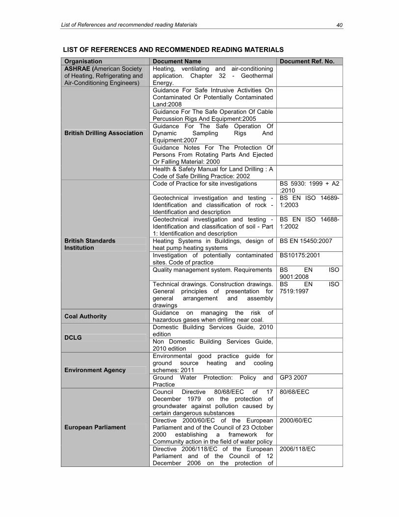
List of References and recommended reading Materials
40
LIST OF REFERENCES AND RECOMMENDED READING MATERIALS
Organisation Document Name Document Ref. No.
ASHRAE (American Society of Heating, Refrigerating and Air-Conditioning Engineers)
Heating, ventilating and air-conditioning application. Chapter 32 - Geothermal Energy.
Guidance For Safe Intrusive Activities On Contaminated Or Potentially Contaminated Land:2008
Guidance For The Safe Operation Of Cable Percussion Rigs And Equipment:2005
Guidance For The Safe Operation Of Dynamic Sampling Rigs And Equipment:2007
Guidance Notes For The Protection Of Persons From Rotating Parts And Ejected Or Falling Material: 2000
British Drilling Association
Health & Safety Manual for Land Drilling : A Code of Safe Drilling Practice: 2002
Code of Practice for site investigations BS 5930: 1999 + A2 :2010
Geotechnical investigation and testing - Identification and classification of rock - Identification and description
BS EN ISO 14689-1:2003
Geotechnical investigation and testing - Identification and classification of soil - Part 1: Identification and description
BS EN ISO 14688-1:2002
Heating Systems in Buildings, design of heat pump heating systems
BS EN 15450:2007
Investigation of potentially contaminated sites. Code of practice
BS10175:2001
Quality management system. Requirements BS EN ISO 9001:2008
British Standards Institution
Technical drawings. Construction drawings. General principles of presentation for general arrangement and assembly drawings
BS EN ISO 7519:1997
Coal Authority Guidance on managing the risk of hazardous gases when drilling near coal.
Domestic Building Services Guide, 2010 edition
DCLG Non Domestic Building Services Guide, 2010 edition
Environmental good practice guide for ground source heating and cooling schemes: 2011
Environment Agency
Ground Water Protection: Policy and Practice
GP3 2007
Council Directive 80/68/EEC of 17 December 1979 on the protection of groundwater against pollution caused by certain dangerous substances
80/68/EEC
Directive 2000/60/EC of the European Parliament and of the Council of 23 October 2000 establishing a framework for Community action in the field of water policy
2000/60/EC European Parliament
Directive 2006/118/EC of the European Parliament and of the Council of 12 December 2006 on the protection of
2006/118/EC
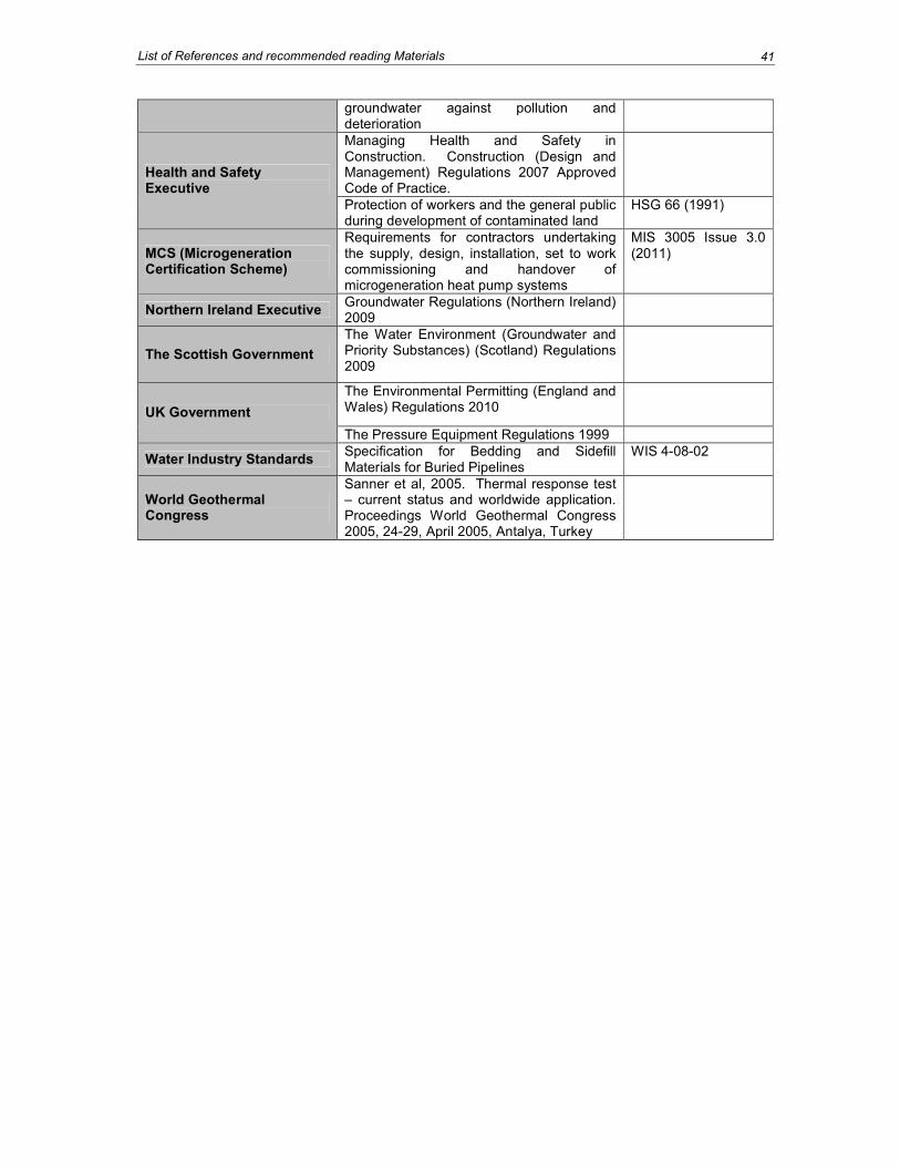
List of References and recommended reading Materials 41
groundwater against pollution and deterioration
Managing Health and Safety in Construction. Construction (Design and Management) Regulations 2007 Approved Code of Practice.
Health and Safety Executive
Protection of workers and the general public during development of contaminated land
HSG 66 (1991)
MCS (Microgeneration Certification Scheme)
Requirements for contractors undertaking the supply, design, installation, set to work commissioning and handover of microgeneration heat pump systems
MIS 3005 Issue 3.0 (2011)
Northern Ireland Executive Groundwater Regulations (Northern Ireland) 2009
The Scottish Government
The Water Environment (Groundwater and Priority Substances) (Scotland) Regulations 2009
The Environmental Permitting (England and Wales) Regulations 2010
UK Government
The Pressure Equipment Regulations 1999
Water Industry Standards Specification for Bedding and Sidefill Materials for Buried Pipelines
WIS 4-08-02
World Geothermal Congress
Sanner et al, 2005. Thermal response test – current status and worldwide application. Proceedings World Geothermal Congress 2005, 24-29, April 2005, Antalya, Turkey