Embed Size (px)
Citation preview

Vertical Slider Section Detail

1
PRODUCT GUIDE
128
69
42
150
139
60
52
48
1830
52
60
1842
90
5218
72
11
18
11
18
VS01 - Outer frame
VS02 - Cill
VS03 - Top Sash VS04 - Standard Sash VS05 - Bottom Rail
VS06Square Bead
24mm
VS07Ovolo Bead
24mm
Main & Bead Profiles
VS14 - Cill
210
189
60

PRODUCT GUIDE
2 2.3
PRODUCT GUIDE
58.5
30.2
53
12.5
22
13.6
5
13.6
5 30 23.6
4.45
15
34
24.4
35.8
12.4
35.8
VS09 - Interlock VS10 - Sash Stop
VS11Narrow
Georgian Bar
VS12Wide
Georgian Bar
VS13Woodgrain
Trim
VSR1OuterframeAluminium
Reinforcement
VSR44sSash Steel
Reinforcement
VSR3sSash Steel
Reinforcement
Ancillary & Reinforcement Profiles
VSR9AluminiumInterlock
58.5
42.2
137502 (White)133502 (Black)Bottom SashBubble Seal
133400Glazing Gasket
10.0
9.0
6.0 6.7
10.0
20.0
70.0
VS23 10mm Packer
VS2120mm Packer
VS20 Coupling
700601Pile Seal9.
5
10.0
70.019
24.4
35.8
VSR5Bottom RailAluminium
Mechanical JointReinforcement
700618 (Brown)700619 (Tan)
Fringe Seal17
.5
3
WEATHER BAR
19.3
WEATHER BAR
Issue A - September 12
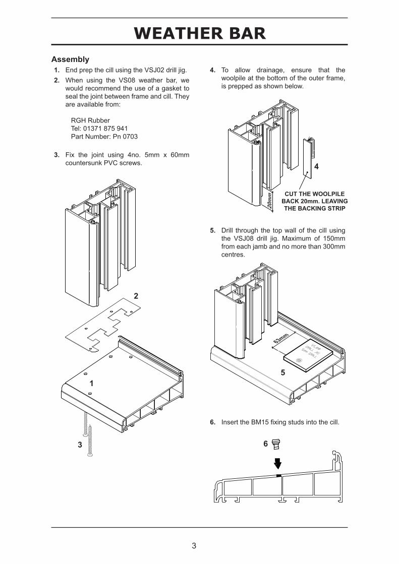
Assembly1. End prep the cill using the VSJ02 drill jig.2. When using the VS08 weather bar, we
would recommend the use of a gasket toseal the joint between frame and cill. Theyare available from:
RGH Rubber Tel: 01371 875 941 Part Number: Pn 0703
3. Fix the joint using 4no. 5mm x 60mmcountersunk PVC screws.
1
2
4. To allow drainage, ensure that thewoolpile at the bottom of the outer frame,is prepped as shown below.
3
5. Drill through the top wall of the cill usingthe VSJ08 drill jig. Maximum of 150mmfrom each jamb and no more than 300mmcentres.
5
6. Insert the BM15 fixing studs into the cill.
6
4
CUT THE WOOLPILE BACK 20mm. LEAVING THE BACKING STRIP20
mm
63mm

19.2
WEATHER BAR
Issue A - September 12 4
WEATHER BAR
7. Cut the VS08 weather bar, cutting size isfinished outer frame size -109mm. Prepeach end as shown below.
Outer Frame -109mm
6mm
6mm
6mm
6mm
8. Cut drainage slots in the back as shownbelow, they should be positioned approx300mm from each end and a maximum of600mm centres. Note: Ensure the slots donot clash with the BM15 fixing studs.
CORNERSREMOVED
5mm 30mm
10. End prep the lower VS10 sash stops asshown below.
200m
m44mm
160º20º
45º
18mm 5.5mm
9. Insert woolpile, and clip the VS08 intoposition.
11. Clip the VS10 sash stops into position.
85º
12. The 133502 & 137502 flexible bubbleseals should not be used at the bottomof the lower sash. To aid fabrication, thewoolpile can be used on all sides.

5
WEATHER BAR
Optional Weather Bar• Improves weathering.• Enhances appearance.• Can be retro fitted.
VS08WEATHER BAR
BM15FIXING STUD
VSJ08DRILL JIG

6
DETAIL SHEETS
VSR1 - Aluminium Reinforcement
VS01 - Outerframe
VS10 - Sash Stop
Lock Keep
VS02 - Cill
VS10 - Sash Stop
LockVS09 - Interlock
Lift Hook
VS06 - Square Bead
VS05 - Bottom Rail with
VSR5 Reinforcement
VS09 - InterlockVS07 - Ovolo
Bead
VS04 - Standard Sash with
VSR44s Reinforcement
VS03 - Top Sashwith
VSR3s Reinforcement
Bubble Seal
Section Through Configuration

4.2
DETAIL SHEETS
7
DETAIL SHEETS
VS07 - Ovolo Bead
VSR3s - SteelReinforcement
VSR1 - AluminiumReinforcement
VS01 Outerframe
VS10 Sash Stop
VS03Top Sash
69.0
35.5
50.0
54.5
V1
V1
(window viewed from outside).
Vertical Section - V1

4.4
DETAIL SHEETS
8
DETAIL SHEETS
VS09 - Interlock
VS09Interlock
VSR44s - SteelReinforcement
VS03 - Top Sash
VS06 - SquareBead
VS04 - Standard Sash
VSR3s - Steel Reinforcement
VS07 - Ovolo Bead
63.050
.6
(window viewed from outside).
V2
V2
Vertical Section - V2

4.6
DETAIL SHEETS
9
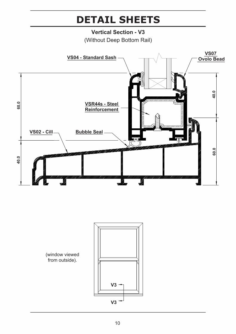
DETAIL SHEETSVertical Section - V3
70.0
60.0
40.0
90.0
(window viewed from outside).
VS14 - Cill
VS05 - Bottom Rail
VS07Ovolo Bead
VSR5 - AluminiumReinforcement
V3
V3
Bubble Seal
VSR5 - AluminiumReinforcement
10
DETAIL SHEETS
4.9
DETAIL SHEETS
40.0
60.0
40.0
60.0
(window viewed from outside).
VS02 - Cill
VS04 - Standard SashVS07
Ovolo Bead
VSR44s - SteelReinforcement
V3
V3
Bubble Seal
Vertical Section - V3(Without Deep Bottom Rail)

4.8
DETAIL SHEETS
11
DETAIL SHEETS
(window viewed from outside).
H1 H1
VS01Outerframe
VSR1Aluminium
Reinforcement
VS07Ovolo Bead
VS03Top Sash
VSR3SSteelReinforcement
57.5 48.0
69.0 36.5
Horizontal Section - H1

4.10
DETAIL SHEETS
12
DETAIL SHEETSHorizontal Section - H2
69.0
42.0 63.5
(window viewed from outside).
VS07 Ovolo Bead
VS04 Standard Sash
VS01 Outerframe
VSR1 Aluminium
Reinforcement
VSR44s - SteelReinforcement
VS10 - Sash Stop
H2 H2

13
DETAIL SHEETS
5.1
CUTTING CALCULATIONSHorizontal Section - H3
140.0
213.0
(window viewed from outside).
VS20Coupling 2mm
VS20 Coupling(Modified)
H3 H3

REINFORCEMENT
14
DRAINAGE
7.1
Reinforcement Location & Fixing Points
VSR1 Aluminium Reinforcement with VS01 Outerframe.
VSR3s Steel Reinforcement with
VS03 Top Sash.
VSR4s Steel Reinforcement with
VS04 Standard Sash.
VSR4s Steel Reinforcement with
VS05 Bottom Rail.
Reinforcement should be secured to the PVC-U profile at a maximum of 100mm from the ends of the reinforcement and then at a maximum of 400mm centres (300mm when using foiled profiles). The recommended screws are self drilling, M4 flat faceted head, TEKS point screws.
Self drill / tap screw M4 x 16mm Countersunk
Facet Head

HARDWARE PREPARATION
8.4
MECHANICAL JOINTS
15
Bottom Rail Assembly
3.5R6.8
1.210.3 30.1 10.4
20.5 10
.8
1.2
18.0
2.5
60m
mBottom Rail End Preparation :
The bottom rail should be end milled with the detail shown below. This ensures a flush joint with the side members of the sash.
Drilling Details :
The two side members of the bottom sash must be prepared before the bottom rail is fixed to it. The bubble seal should be cut back 60mm (as shown), and then the profile should be pre-drilled using the VSJ05. The jig (VSJ05) is located as shown. Two 5mm diameter holes are then drilled through the section, these are to provide clearance for the two screws used to mechanically join the bottom rail.
Bottom Rail & Sash Assembly :
The VSM06 mouldings (left & right handed) are required when assembling the bottom rail with the side members.1) Insert the moulding intothe bottom of the sash side member. The screws pass through the clearance holes in the moulding and into the screw ports in the side members profile.
2) Locate the moulding in the bottom rail usingthe location lugs. Then using two screws, secure the side member to the bottom rail. The screws pass through the clearance holes in the side members and into the screw ports in the bottom rail reinforcement (VSR4S).
Self drill / tap screw 3.9 x 38mm Countersunk
Self tap screw 5.5 x 55mm Countersunk

16
MECHANICAL JOINTSCill Assembly with Outerframe Side Jambs
Drill Jig
VS02 CillCill Drilling Details :
The cill (VS02 or VS14) is to be drilled at both ends. The drill jig (VSJ02) is positioned as shown. The arrows show the direction of the force required to locate the jig.
Four holes are to be drilled through the cill section. The holes are required for mechanically joining the outer frames vertical members to the cill. A 5mm diameter drill should be used to give clearance holes for the screws used to secure the outer frame.
Fastening Side Jambs :
Each of the side jambs is attached to the cill using four screws. The screws pass up through the cill (through the clearance holes), they are then screwed into the screw ports in the outerframe profile. This ensures that the side jambs are located correctly.
When fixing the cill, ensure the following has been done :1) The pile seal has been put in both the cill andthe outerframe.2) That all of the necessary slide gearing hasbeen put into the relevant chambers. 3) The bottom of each of the side jambs hasbeen cut at 5 degrees (in the correct direction).
- A silicone seal is required around the joint where the side jamb meets the cill.
Self tap screw 5.0 x 60mm Countersunk
Note: The cill jig is designed for use with cills cut to the overall width of the window. If the cill size has been adjusted to allow for the end caps then they must be fitted prior to positioning the jig.
Drill Jig
VS14 Cill