Embed Size (px)
Citation preview
NORBIT Aptomar BlueDeal monitoring and reporting
APT-BD-04- Oil Spill and Ice Detection Manual for Handheld Thermal Camera
EXAMPLE REPORT
Customer: Aptoil AS Norge AS
Location and time: Barents Sea, Q3-Q4 2018
Field: Rogar
aptomarsafety at your fingertips

A Stiklestadveien 3 7041 Trondheim T +47 40 00 34 03 O NO 988 567 256Norway F +47 73 51 00 84 W www.aptomar.com
First edition: 2017-11-14Last revised: 2018-06-20
OSD manual-handheld IR

The information in this document is subject to change without notice and should not beconstrued as a commitment by Aptomar AS. Aptomar AS assumes no responsibility for any
errors that may appear in this document.
Except as may be expressly stated elsewhere in this document, nothing herein shall beconstrued as any kind of guarantee or warranty by Aptomar AS for losses, damages to
persons or property, suitability for a specifc purpose or the like.
In no event shall Aptomar AS be liable for incidental or consequential damages arising fromuse of this document or of the software and hardware described in this document.
We reserve all rights for this document and the information contained therein. Reproduction,use, or disclosure to third parties without express authority is strictly forbidden.
Additional copies of this document may be obtained from Aptomar AS at its then currentcharge.
© Copyright 2018 Aptomar AS - All rights reserved.Aptomar AS
Stiklestadveien 37041 Trondheim
Norway
Table of Contents
Table of Contents
1 Introduction............................................................................................................................................. 7
1.1 Clean-to-Operate (CTO), Oil Spill Detection (OSD) and ice (ICE) monitoring...............................................7
2 The BlueDeal handheld IR-camera package.............................................................................................9
2.1 Contents of the camera case....................................................................................................................92.2 General information about the camera...................................................................................................102.3 Camera features and controls................................................................................................................112.4 Using the camera.................................................................................................................................. 122.5 Connecting the camera to PC and transfer of fles..................................................................................142.6 Uploading the fles to the Aptomar BlueDeal online portal.......................................................................14
3 The monitoring procedure......................................................................................................................16
3.1 IR-imaging in general............................................................................................................................ 163.2 Oil spill detection................................................................................................................................... 183.3 Ice detection......................................................................................................................................... 203.4 So what to look for?............................................................................................................................... 223.5 Oil spill and ice monitoring from the STB vessel.....................................................................................243.6 Charging the camera............................................................................................................................. 273.7 Cleaning the lens................................................................................................................................... 273.8 Aptomarin............................................................................................................................................. 27
4 Camera user description......................................................................................................................... 28
4.1 General cautions................................................................................................................................... 284.2 Camera software................................................................................................................................... 284.3 Installing/re-installing the SD card..........................................................................................................284.4 Installing the batteries........................................................................................................................... 294.5 Charging the camera............................................................................................................................. 294.6 BHM-series bi-ocular power management..............................................................................................304.7 Buttons and controls............................................................................................................................. 314.8 Batteries............................................................................................................................................... 354.9 SD card................................................................................................................................................. 364.10 Auto-standby operation........................................................................................................................ 374.11 The hot shoe....................................................................................................................................... 394.12 Image capture and storage..................................................................................................................394.13 Technical data sheet............................................................................................................................ 41
5

Abbrevations
IR – InfraredCTO – Clean to OperateOSD – Oil Spill DetectionICE – Ice DetectionIFW – Ice Free WatersNEA – Norwegian Environmental AgencyOBM – Oil-based MudOIM – Offshore Installation Manager
6
1 Introduction
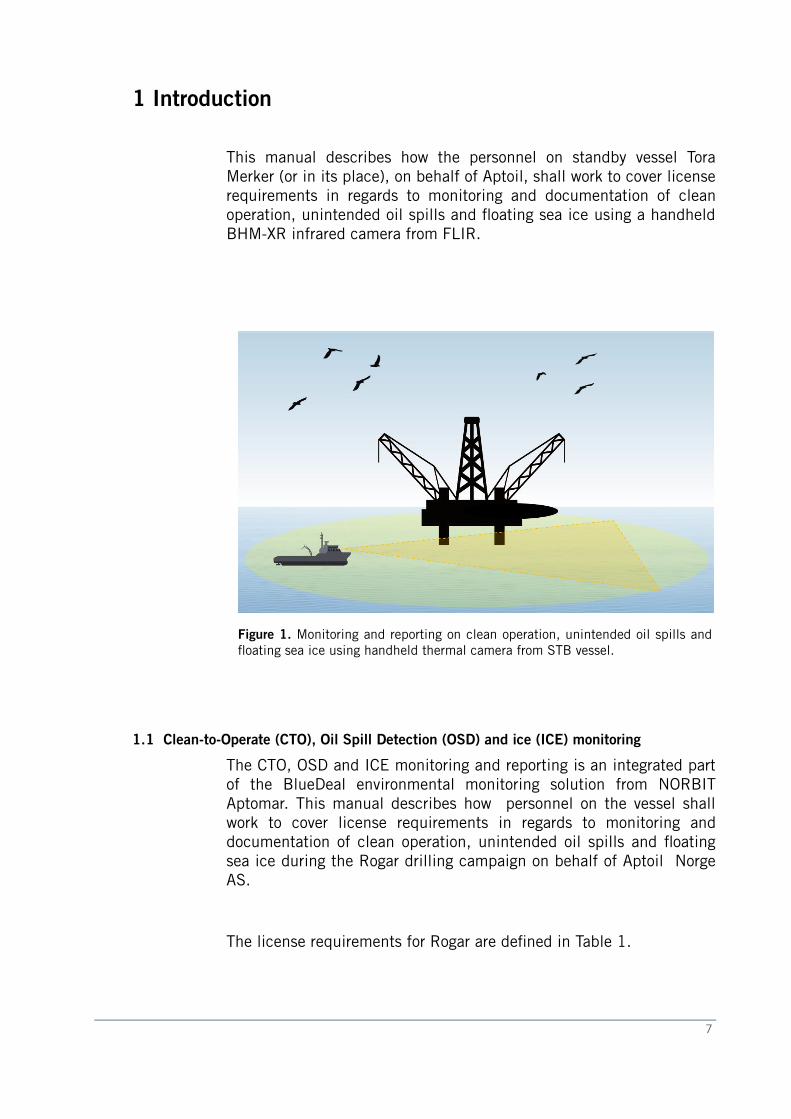
This manual describes how the personnel on standby vessel ToraMerker (or in its place), on behalf of Aptoil, shall work to cover licenserequirements in regards to monitoring and documentation of cleanoperation, unintended oil spills and foating sea ice using a handheldBHM-XR infrared camera from FLIR.
Figure 1. Monitoring and reporting on clean operation, unintended oil spills andfoating sea ice using handheld thermal camera from STB vessel.
1.1 Clean-to-Operate (CTO), Oil Spill Detection (OSD) and ice (ICE) monitoring
The CTO, OSD and ICE monitoring and reporting is an integrated partof the BlueDeal environmental monitoring solution from NORBITAptomar. This manual describes how personnel on the vessel shallwork to cover license requirements in regards to monitoring anddocumentation of clean operation, unintended oil spills and foatingsea ice during the Rogar drilling campaign on behalf of Aptoil NorgeAS.
The license requirements for Rogar are defned in Table 1.
7
1 Introduction
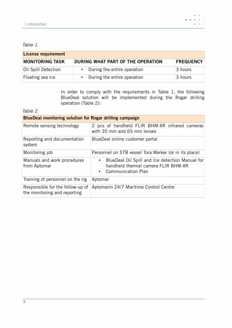
Table 1.
License requirement
MONITORING TASK DURING WHAT PART OF THE OPERATION FREQUENCY
Oil Spill Detection • During the entire operation 3 hours
Floating sea ice • During the entire operation 3 hours
In order to comply with the requirements in Table 1, the followingBlueDeal solution will be implemented during the Rogar drillingoperation (Table 2):
Table 2. BlueDeal monitoring solution for Rogar drilling campaign
Remote sensing technology 2 pcs of handheld FLIR BHM-XR infrared cameraswith 35 mm and 65 mm lenses
Reporting and documentation system
BlueDeal online customer portal
Monitoring job Personnel on STB vessel Tora Merker (or in its place)
Manuals and work procedures from Aptomar
• BlueDeal Oil Spill and Ice detection Manual forhandheld thermal camera FLIR BHM-XR
• Communication Plan
Training of personnel on the rig Aptomar
Responsible for the follow-up ofthe monitoring and reporting
Aptomarin 24/7 Maritime Control Centre
8
2 The BlueAptoil l handheld IR-camera package
2.1 Contents of the camera case
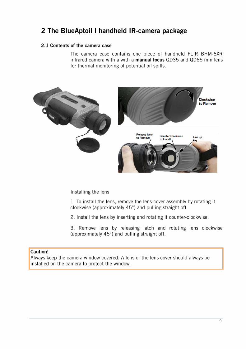
The camera case contains one piece of handheld FLIR BHM-6XRinfrared camera with a with a manual focus QD35 and QD65 mm lensfor thermal monitoring of potential oil spills.
Installing the lens
1. To install the lens, remove the lens-cover assembly by rotating it clockwise (approximately 45°) and pulling straight off
2. Install the lens by inserting and rotating it counter-clockwise.
3. Remove lens by releasing latch and rotating lens clockwise(approximately 45°) and pulling straight off.
Caution!Always keep the camera window covered. A lens or the lens cover should always be installed on the camera to protect the window.
9
2 The BlueAptoil l handheld IR-camera package
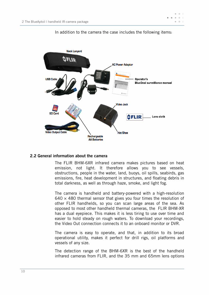
In addition to the camera the case includes the following items:
2.2 General information about the camera
The FLIR BHM-6XR infrared camera makes pictures based on heatemission, not light. It therefore allows you to see vessels,obstructions, people in the water, land, buoys, oil spills, seabirds, gasemissions, fre, heat development in structures, and foating debris intotal darkness, as well as through haze, smoke, and light fog.
The camera is handheld and battery-powered with a high-resolution640 × 480 thermal sensor that gives you four times the resolution ofother FLIR handhelds, so you can scan large areas of the sea. Asopposed to most other handheld thermal cameras, the FLIR BHM-XRhas a dual eyepiece. This makes it is less tiring to use over time andeasier to hold steady on rough waters. To download your recordings,the Video Out connection connects it to an onboard monitor or DVR.
The camera is easy to operate, and that, in addition to its broadoperational utility, makes it perfect for drill rigs, oil platforms andvessels of any size.
The detection range of the BHM-6XR is the best of the handheldinfrared cameras from FLIR, and the 35 mm and 65mm lens options
10
that comes with your camera package gives the best combination ofresolution (upper detection limit) and feld-of-view.
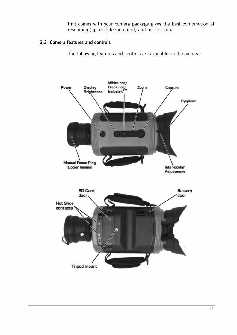
2.3 Camera features and controls
The following features and controls are available on the camera:
11
2 The BlueAptoil l handheld IR-camera package
2.4 Using the camera
See Chapter 4 for full user description of the FLIR BHM-XR camera:
4.1 General cautions (s. 28)
4.2 Camera software (s. 28)
4.3 Installing/re-installing the SD card (s. 28)
4.4 Batteries (s. 29)
4.5 Charging the camera (s. 29)
4.6 Power management (s. 30)
4.7 Buttons and controls (s. 31)
4.8 Batteries (s. 35)
4.9 SD card (s. 36)
4.10 Auto standby operation (s. 37)
4.11 The hot shoe (s. 39)
4.12 Image capture and storage (s. 39)
4.13 Technical data sheet (s. 41)
2.4.1 Practical use of the camera based on experience
Based on experience from earlier drilling campaigns, the 35 mm lensis most suitable for overview monitoring, because 1) a signifcantlylarger area of the sea surface can be covered at one time (Figure 2and 3), and 2) it does not require a completely still hand. Even theslightest movement of the hands caused by rough wind or shaking ofthe hands due to freezing, give blurry images with the 65 mm lens.So although theory states that the range of the 65mm lens isapproximately 800 m longer than the 35mm lens, the monitoringcrews on earlier campaigns have reported that this was not the case inpractice (at least not at sea). The fnal conclusion is therefore thatthe 35 mm lens option is the optimal choice for maritime infrared oilspill monitoring:
1. It allows sweeping over larger areas of the sea
2. It provides sharper images (also in moist weather)
3. It gives a much better situation overview (which is crucialduring an oil spill incident/accident)
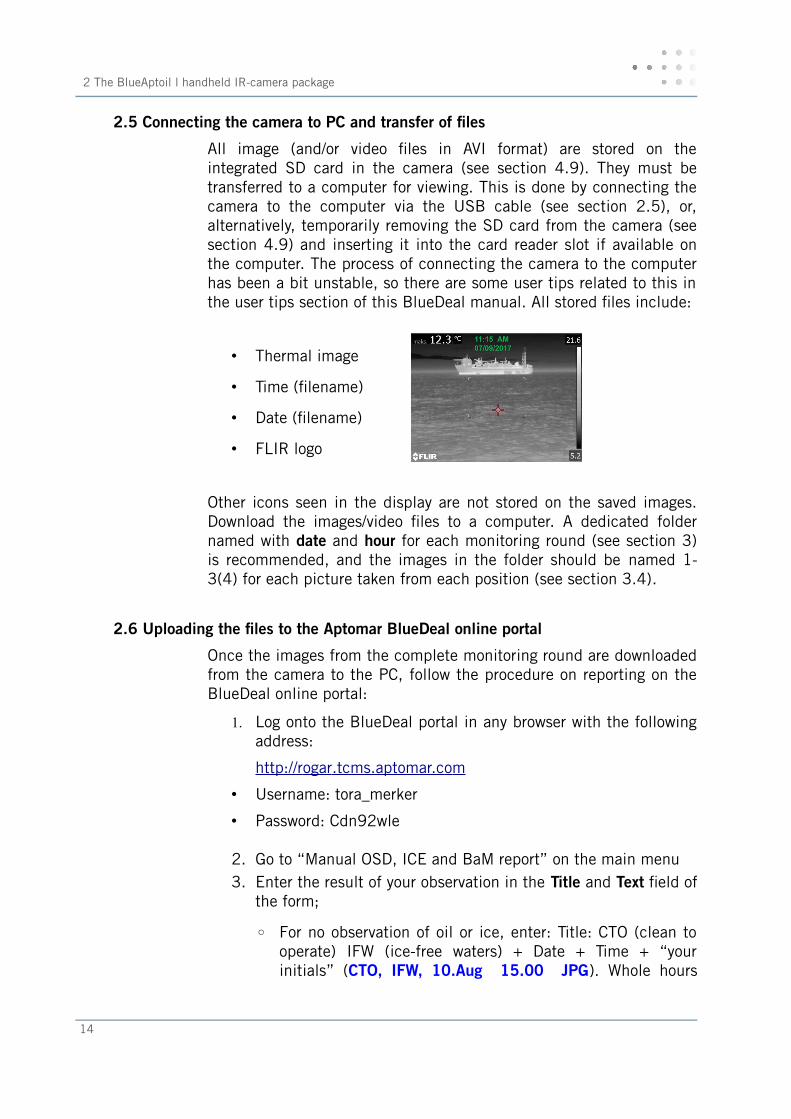
The 35 mm lens gives a range of a minimum 1.3 nautical miles (2.4km; the distance from the observer to the vessel in Figure 3).
12
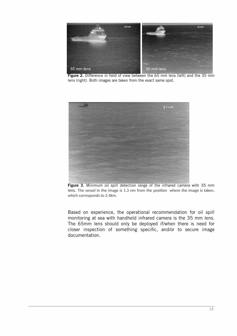
Figure 2. Difference in feld of view between the 65 mm lens (left) and the 35 mmlens (right). Both images are taken from the exact same spot.
Figure 3. Minimum oil spill detection range of the infrared camera with 35 mmlens. The vessel in the image is 1.3 nm from the positon where the image is taken,which corresponds to 2.4km.
Based on experience, the operational recommendation for oil spillmonitoring at sea with handheld infrared camera is the 35 mm lens.The 65mm lens should only be deployed if/when there is need forcloser inspection of something specifc, and/or to secure imagedocumentation.
13
2 The BlueAptoil l handheld IR-camera package
2.5 Connecting the camera to PC and transfer of fles
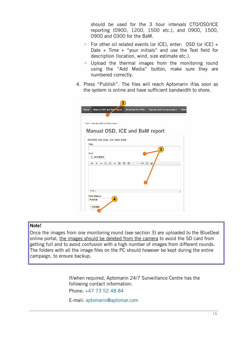
All image (and/or video fles in AVI format) are stored on theintegrated SD card in the camera (see section 4.9). They must betransferred to a computer for viewing. This is done by connecting thecamera to the computer via the USB cable (see section 2.5), or,alternatively, temporarily removing the SD card from the camera (seesection 4.9) and inserting it into the card reader slot if available onthe computer. The process of connecting the camera to the computerhas been a bit unstable, so there are some user tips related to this inthe user tips section of this BlueDeal manual. All stored fles include:
• Thermal image
• Time (flename)
• Date (flename)
• FLIR logo
Other icons seen in the display are not stored on the saved images.Download the images/video fles to a computer. A dedicated foldernamed with date and hour for each monitoring round (see section 3)is recommended, and the images in the folder should be named 1-3(4) for each picture taken from each position (see section 3.4).
2.6 Uploading the fles to the Aptomar BlueDeal online portal
Once the images from the complete monitoring round are downloadedfrom the camera to the PC, follow the procedure on reporting on theBlueDeal online portal:
1. Log onto the BlueDeal portal in any browser with the followingaddress:
http://r ogar .tcms.aptomar.c o m
• Username: tora_merker
• Password: Cdn92wle
2. Go to “Manual OSD, ICE and BaM report” on the main menu3. Enter the result of your observation in the Title and Text feld of
the form;
◦ For no observation of oil or ice, enter: Title: CTO (clean tooperate) IFW (ice-free waters) + Date + Time + “yourinitials” (CTO, IFW, 10.Aug 15.00 JPG). Whole hours
14
should be used for the 3 hour intervals CTO/OSD/ICEreporting (0900, 1200, 1500 etc.), and 0900, 1500,0900 and 0300 for the BaM.
◦ For other oil related events (or ICE), enter: OSD (or ICE) +Date + Time + “your initials” and use the Text feld fordescription (location, wind, size estimate etc.).
◦ Upload the thermal images from the monitoring roundusing the “Add Media” button, make sure they arenumbered correctly.
4. Press “Publish”. The fles will reach Aptomarin if/as soon asthe system is online and have suffcient bandwidth to shore.
Note!Once the images from one monitoring round (see section 3) are uploaded to the BlueDeal online portal, the images should be deleted from the camera to avoid the SD card from getting full and to avoid confusion with a high number of images from different rounds. The folders with all the image fles on the PC should however be kept during the entire campaign, to ensure backup.
If/when required, Aptomarin 24/7 Surveillance Centre has the following contact information:Phone: +47 73 52 48 84
E-mail: [email protected]
15
3 The monitoring procedure
3 The monitoring procedure
3.1 IR-imaging in general
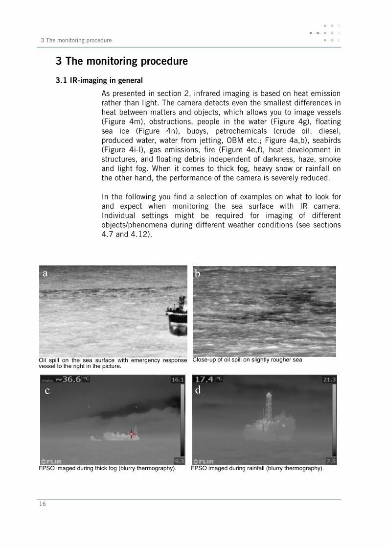
As presented in section 2, infrared imaging is based on heat emissionrather than light. The camera detects even the smallest differences inheat between matters and objects, which allows you to image vessels(Figure 4m), obstructions, people in the water (Figure 4g), foatingsea ice (Figure 4n), buoys, petrochemicals (crude oil, diesel,produced water, water from jetting, OBM etc.; Figure 4a,b), seabirds(Figure 4i-l), gas emissions, fre (Figure 4e,f), heat development instructures, and foating debris independent of darkness, haze, smokeand light fog. When it comes to thick fog, heavy snow or rainfall onthe other hand, the performance of the camera is severely reduced.
In the following you fnd a selection of examples on what to look forand expect when monitoring the sea surface with IR camera.Individual settings might be required for imaging of differentobjects/phenomena during different weather conditions (see sections4.7 and 4.12).
Oil spill on the sea surface with emergency responsevessel to the right in the picture.
Close-up of oil spill on slightly rougher sea
FPSO imaged during thick fog (blurry thermography). FPSO imaged during rainfall (blurry thermography).
16
a b
c d
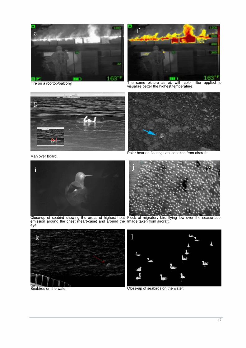
Fire on a rooftop/balcony. The same picture as e), with color flter applied tovisualize better the highest temperature.
Man over board.Polar bear on foating sea ice taken from aircraft.
Close-up of seabird showing the areas of highest heatemission around the chest (heart-case) and around theeye.
Flock of migratory bird fying low over the seasurface.Image taken from aircraft.
Seabirds on the water. Close-up of seabirds on the water.
17
f
g
i j
k l
e f
h
3 The monitoring procedure
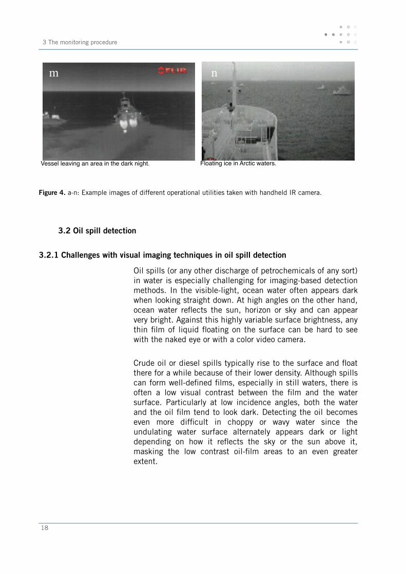
Vessel leaving an area in the dark night.
Floating ice in Arctic waters.
Figure 4. a-n: Example images of different operational utilities taken with handheld IR camera.
3.2 Oil spill detection
3.2.1 Challenges with visual imaging techniques in oil spill detection
Oil spills (or any other discharge of petrochemicals of any sort)in water is especially challenging for imaging-based detectionmethods. In the visible-light, ocean water often appears darkwhen looking straight down. At high angles on the other hand,ocean water refects the sun, horizon or sky and can appearvery bright. Against this highly variable surface brightness, anythin flm of liquid foating on the surface can be hard to seewith the naked eye or with a color video camera.
Crude oil or diesel spills typically rise to the surface and foatthere for a while because of their lower density. Although spillscan form well-defned flms, especially in still waters, there isoften a low visual contrast between the flm and the watersurface. Particularly at low incidence angles, both the waterand the oil flm tend to look dark. Detecting the oil becomeseven more diffcult in choppy or wavy water since theundulating water surface alternately appears dark or lightdepending on how it refects the sky or the sun above it,masking the low contrast oil-flm areas to an even greaterextent.
18
m nnnnn
3.2.2 IR imaging in oil spill detection
By using a long wavelength infrared camera for oil spillmonitoring and detection, the contrast betweenpetrochemicals and water can be signifcantly increased in avariety of different sea states and lighting conditions:
Variability of different light levels The infrared images are very uniform with changing lightlevels. The infrared images are always lit by heat emissionfrom the scene itself, do not require illumination at night, andhave an appearance that changes very little between day andnight.
Variability created by refection in the Visible light spectrum Since most of the thermal infrared radiation one sees with theinfrared camera is emitted by the water surface itself ratherthan being refected, the surface looks much more uniform.This brightness uniformity found in the infrared images makesvisual detection of oil spills much easier.
Ability to render a clear, high contrast image Oil or diesel flm on the surface of water tends to look quitedifferent from the water itself in the infrared images, givingfoating flms of petrochemicals a distinct appearance. In thevisible band, oil flms can be very hard to see unless thelighting and viewing angles are just right, or the flm is dirty,thick crude oil. In the infrared videos/images of oil flms aremuch less sensitive to these factors.
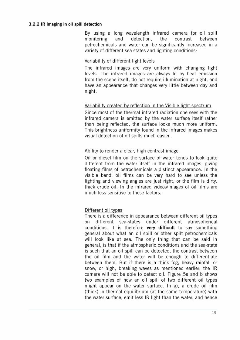
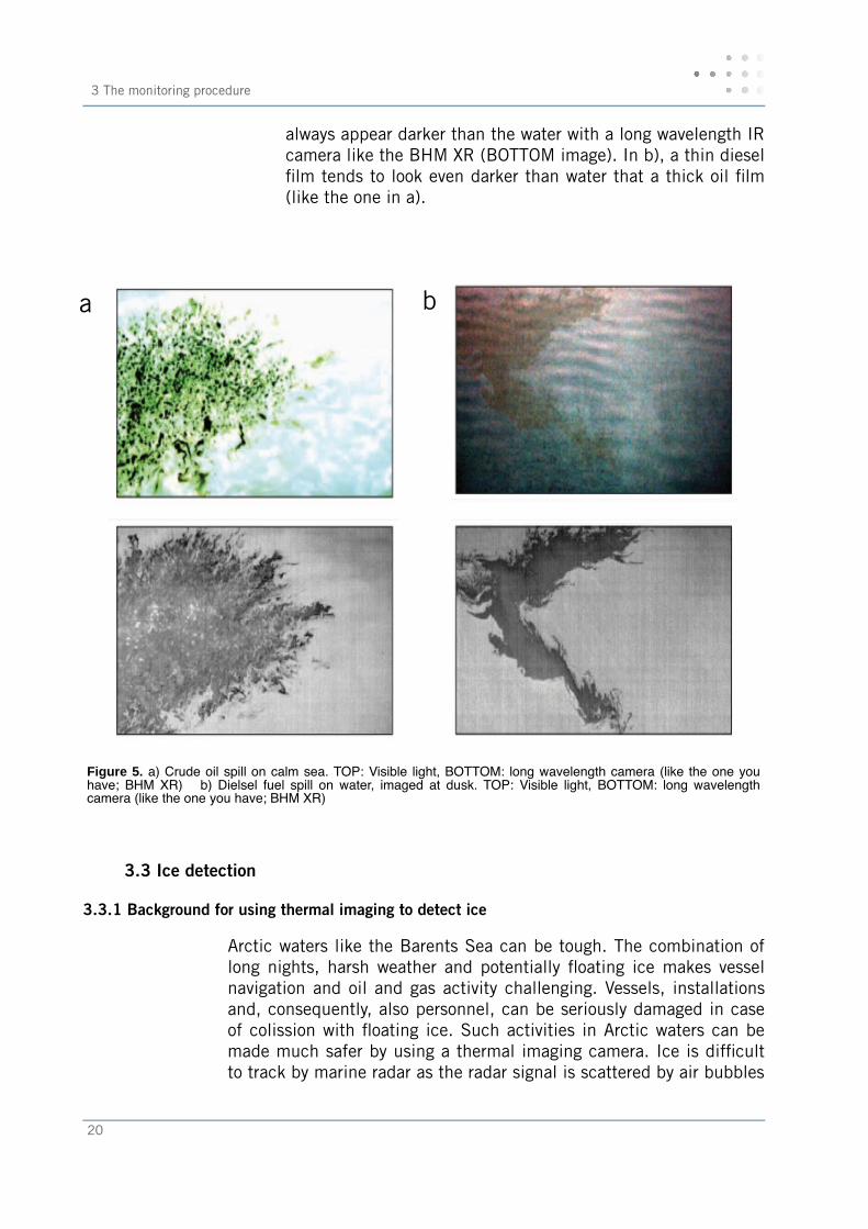
Different oil typesThere is a difference in appearance between different oil typeson different sea-states under different atmosphericalconditions. It is therefore very diffcult to say somethinggeneral about what an oil spill or other spilt petrochemicalswill look like at sea. The only thing that can be said ingeneral, is that if the atmospheric conditions and the sea-stateis such that an oil spill can be detected, the contrast betweenthe oil flm and the water will be enough to differentiatebetween them. But if there is a thick fog, heavy rainfall orsnow, or high, breaking waves as mentioned earlier, the IRcamera will not be able to detect oil. Figure 5a and b showstwo examples of how an oil spill of two different oil typesmight appear on the water surface. In a), a crude oil flm(thick) in thermal equilibrium (at the same temperature) withthe water surface, emit less IR light than the water, and hence
19
3 The monitoring procedure
always appear darker than the water with a long wavelength IRcamera like the BHM XR (BOTTOM image). In b), a thin dieselflm tends to look even darker than water that a thick oil flm(like the one in a).
Figure 5. a) Crude oil spill on calm sea. TOP: Visible light, BOTTOM: long wavelength camera (like the one youhave; BHM XR) b) Dielsel fuel spill on water, imaged at dusk. TOP: Visible light, BOTTOM: long wavelengthcamera (like the one you have; BHM XR)
3.3 Ice detection
3.3.1 Background for using thermal imaging to detect ice
Arctic waters like the Barents Sea can be tough. The combination oflong nights, harsh weather and potentially foating ice makes vesselnavigation and oil and gas activity challenging. Vessels, installationsand, consequently, also personnel, can be seriously damaged in caseof colission with foating ice. Such activities in Arctic waters can bemade much safer by using a thermal imaging camera. Ice is diffcultto track by marine radar as the radar signal is scattered by air bubbles
20
a b
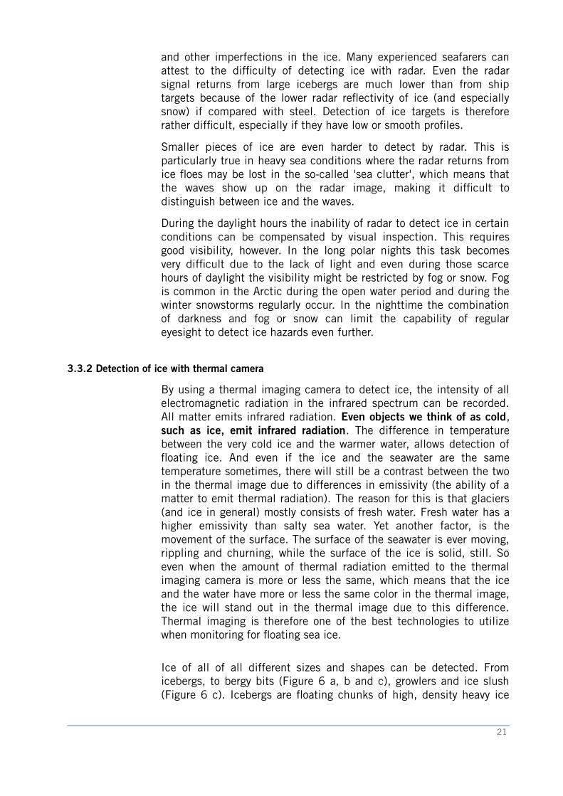
and other imperfections in the ice. Many experienced seafarers canattest to the diffculty of detecting ice with radar. Even the radarsignal returns from large icebergs are much lower than from shiptargets because of the lower radar refectivity of ice (and especiallysnow) if compared with steel. Detection of ice targets is thereforerather diffcult, especially if they have low or smooth profles.
Smaller pieces of ice are even harder to detect by radar. This isparticularly true in heavy sea conditions where the radar returns fromice foes may be lost in the so-called 'sea clutter', which means thatthe waves show up on the radar image, making it diffcult todistinguish between ice and the waves.
During the daylight hours the inability of radar to detect ice in certainconditions can be compensated by visual inspection. This requiresgood visibility, however. In the long polar nights this task becomesvery diffcult due to the lack of light and even during those scarcehours of daylight the visibility might be restricted by fog or snow. Fogis common in the Arctic during the open water period and during thewinter snowstorms regularly occur. In the nighttime the combinationof darkness and fog or snow can limit the capability of regulareyesight to detect ice hazards even further.
3.3.2 Detection of ice with thermal camera
By using a thermal imaging camera to detect ice, the intensity of allelectromagnetic radiation in the infrared spectrum can be recorded.All matter emits infrared radiation. Even objects we think of as cold,such as ice, emit infrared radiation. The difference in temperaturebetween the very cold ice and the warmer water, allows detection offoating ice. And even if the ice and the seawater are the sametemperature sometimes, there will still be a contrast between the twoin the thermal image due to differences in emissivity (the ability of amatter to emit thermal radiation). The reason for this is that glaciers(and ice in general) mostly consists of fresh water. Fresh water has ahigher emissivity than salty sea water. Yet another factor, is themovement of the surface. The surface of the seawater is ever moving,rippling and churning, while the surface of the ice is solid, still. Soeven when the amount of thermal radiation emitted to the thermalimaging camera is more or less the same, which means that the iceand the water have more or less the same color in the thermal image,the ice will stand out in the thermal image due to this difference.Thermal imaging is therefore one of the best technologies to utilizewhen monitoring for foating sea ice.
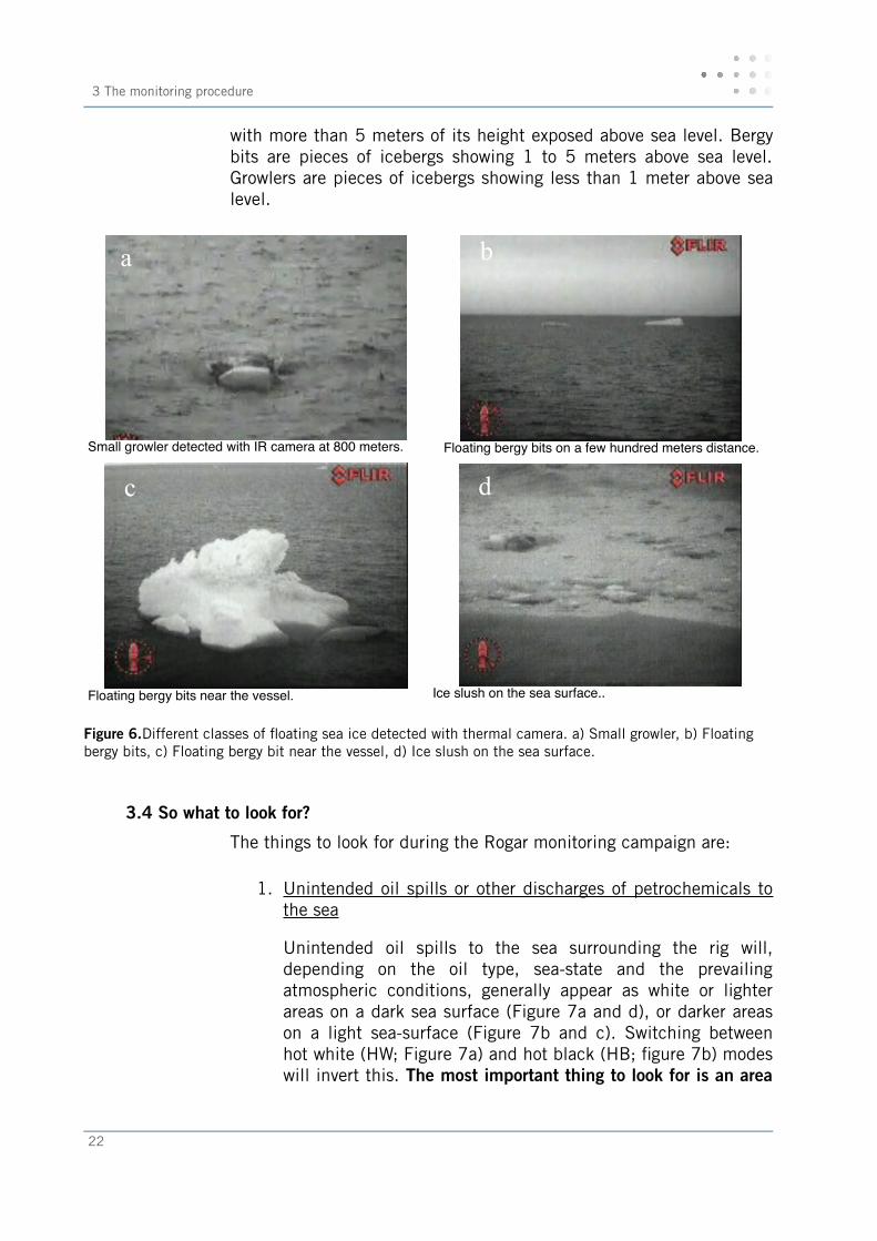
Ice of all of all different sizes and shapes can be detected. Fromicebergs, to bergy bits (Figure 6 a, b and c), growlers and ice slush(Figure 6 c). Icebergs are foating chunks of high, density heavy ice
21
3 The monitoring procedure
with more than 5 meters of its height exposed above sea level. Bergybits are pieces of icebergs showing 1 to 5 meters above sea level.Growlers are pieces of icebergs showing less than 1 meter above sealevel.
Small growler detected with IR camera at 800 meters. Floating bergy bits on a few hundred meters distance.
Floating bergy bits near the vessel. Ice slush on the sea surface..
Figure 6.Different classes of foating sea ice detected with thermal camera. a) Small growler, b) Floating bergy bits, c) Floating bergy bit near the vessel, d) Ice slush on the sea surface.
3.4 So what to look for?
The things to look for during the Rogar monitoring campaign are:
1. Unintended oil spills or other discharges of petrochemicals to the sea
Unintended oil spills to the sea surrounding the rig will,depending on the oil type, sea-state and the prevailingatmospheric conditions, generally appear as white or lighterareas on a dark sea surface (Figure 7a and d), or darker areason a light sea-surface (Figure 7b and c). Switching betweenhot white (HW; Figure 7a) and hot black (HB; fgure 7b) modeswill invert this. The most important thing to look for is an area
22
a b
c d
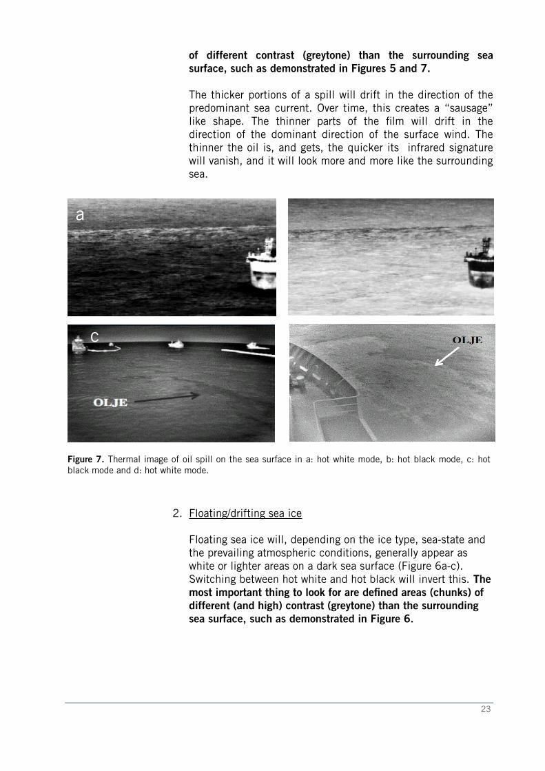
of different contrast (greytone) than the surrounding seasurface, such as demonstrated in Figures 5 and 7.
The thicker portions of a spill will drift in the direction of thepredominant sea current. Over time, this creates a “sausage”like shape. The thinner parts of the flm will drift in thedirection of the dominant direction of the surface wind. Thethinner the oil is, and gets, the quicker its infrared signaturewill vanish, and it will look more and more like the surroundingsea.
Figure 7. Thermal image of oil spill on the sea surface in a: hot white mode, b: hot black mode, c: hotblack mode and d: hot white mode.
2. Floating/drifting sea ice
Floating sea ice will, depending on the ice type, sea-state and the prevailing atmospheric conditions, generally appear as white or lighter areas on a dark sea surface (Figure 6a-c). Switching between hot white and hot black will invert this. Themost important thing to look for are defned areas (chunks) of different (and high) contrast (greytone) than the surrounding sea surface, such as demonstrated in Figure 6.
23
a b
c d
3 The monitoring procedure
3.5 Oil spill and ice monitoring from the STB vessel
The operational procedure of the Clean-to-Operate, Oil Spill Detectionand ice monitoring from the vessel are described in the followingchapters.
3.5.1 The monitoring position
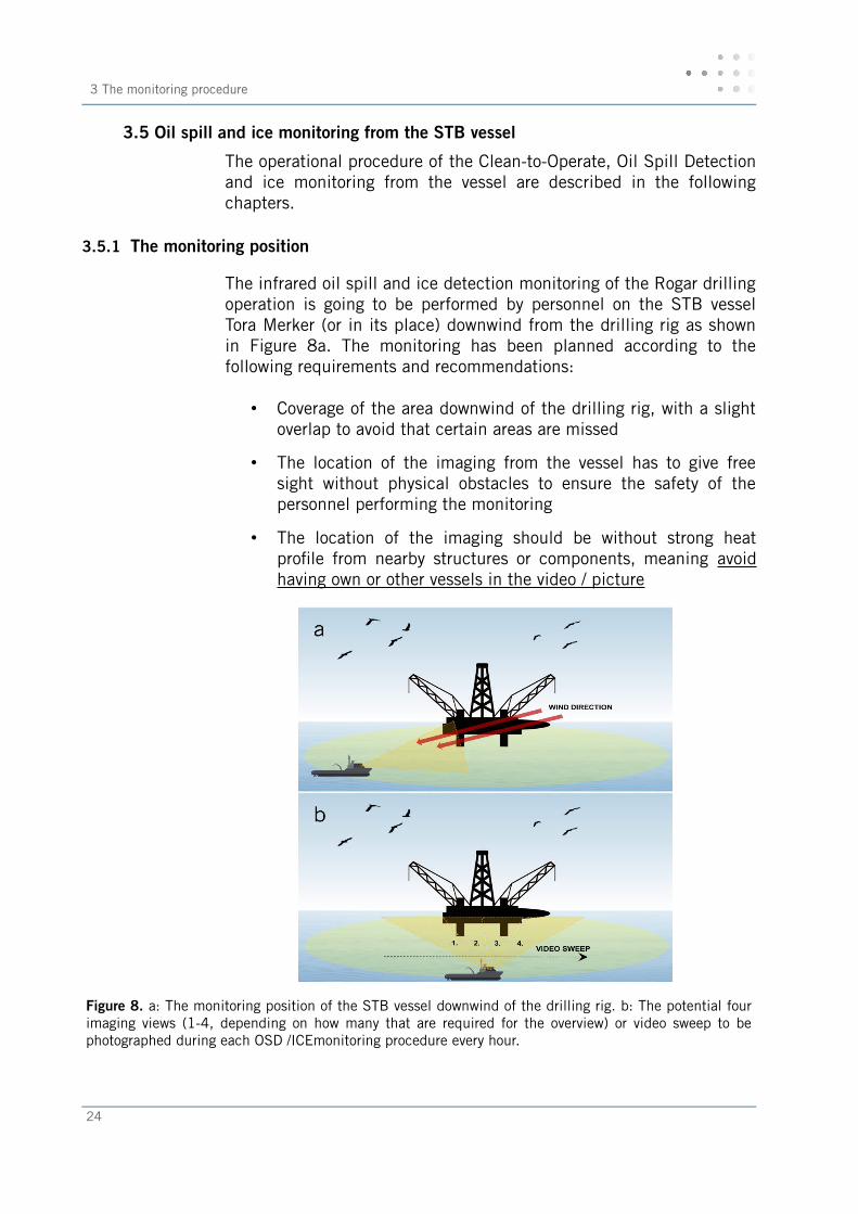
The infrared oil spill and ice detection monitoring of the Rogar drillingoperation is going to be performed by personnel on the STB vesselTora Merker (or in its place) downwind from the drilling rig as shownin Figure 8a. The monitoring has been planned according to thefollowing requirements and recommendations:
• Coverage of the area downwind of the drilling rig, with a slightoverlap to avoid that certain areas are missed
• The location of the imaging from the vessel has to give freesight without physical obstacles to ensure the safety of thepersonnel performing the monitoring
• The location of the imaging should be without strong heatprofle from nearby structures or components, meaning avoidhaving own or other vessels in the video / picture
Figure 8. a: The monitoring position of the STB vessel downwind of the drilling rig. b: The potential fourimaging views (1-4, depending on how many that are required for the overview) or video sweep to bephotographed during each OSD /ICEmonitoring procedure every hour.
24
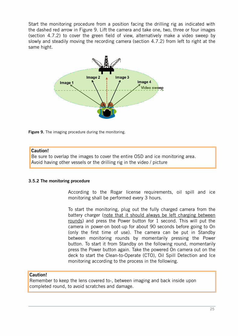
Start the monitoring procedure from a position facing the drilling rig as indicated withthe dashed red arrow in Figure 9. Lift the camera and take one, two, three or four images(section 4.7.2) to cover the green feld of view, alternatively make a video sweep byslowly and steadily moving the recording camera (section 4.7.2) from left to right at thesame hight.
Figure 9. The imaging procedure during the monitoring.
Caution!Be sure to overlap the images to cover the entire OSD and ice monitoring area. Avoid having other vessels or the drilling rig in the video / picture
3.5.2 The monitoring procedure
According to the Rogar license requirements, oil spill and icemonitoring shall be performed every 3 hours.
To start the monitoring, plug out the fully charged camera from thebattery charger (note that it should always be left charging betweenrounds) and press the Power button for 1 second. This will put thecamera in power-on boot-up for about 90 seconds before going to On(only the frst time of use). The camera can be put in Standbybetween monitoring rounds by momentarily pressing the Powerbutton. To start it from Standby on the following round, momentarilypress the Power button again. Take the powered On camera out on thedeck to start the Clean-to-Operate (CTO), Oil Spill Detection and Icemonitoring according to the process in the following.
Caution!Remember to keep the lens covered to-, between imaging and back inside upon completed round, to avoid scratches and damage.
25
3 The monitoring procedure
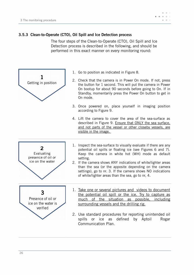
3.5.3 Clean-to-Operate (CTO), Oil Spill and Ice Detection process
The four steps of the Clean-to-Operate (CTO), Oil Spill and Ice Detection process is described in the following, and should be performed in this exact manner on every monitoring round:
1. Go to position as indicated in Figure 8.
2. Check that the camera is in Power On mode. If not, pressthe button for 1 second. This will put the camera in PowerOn bootup for about 90 seconds before going to On. If inStandby, momentarily press the Power On button to get inOn mode.
3. Once powered on, place yourself in imaging positionaccording to Figure 9.
4. Lift the camera to cover the area of the sea-surface asdescribed in Figure 9. Ensure that ONLY the sea surface,and not parts of the vessel or other closeby vessels, arevisible in the image.
1. Inspect the sea-surface to visually evaluate if there are anypotential oil spills or foating ice (see Figures 6 and 7).Keep the camera in white hot (WH) mode as defaultsetting.
2. If the camera shows ANY indications of white/lighter areasthan the sea (or the apposite depending on the camerasettings), go to nr. 3. If the camera shows NO indicationsof white/lighter areas than the sea, go to nr, 4.
1. Take one or several pictures and videos to document the potential oil spill or the ice. Try to capture asmuch of the situation as possible, includingsurrounding vessels and the drilling rig.
2. Use standard procedures for reporting unintended oilspills or ice as defned by Aptoil RogarCommunication Plan.
26
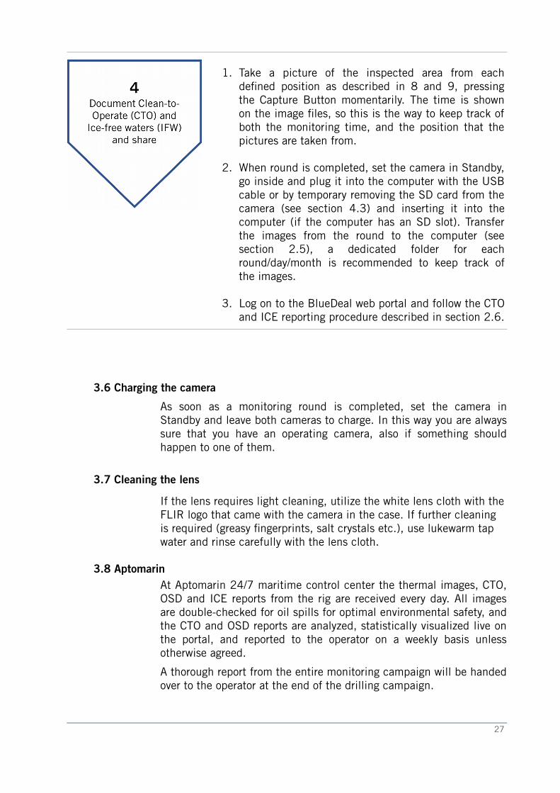
1. Take a picture of the inspected area from eachdefned position as described in 8 and 9, pressingthe Capture Button momentarily. The time is shownon the image fles, so this is the way to keep track ofboth the monitoring time, and the position that thepictures are taken from.
2. When round is completed, set the camera in Standby,go inside and plug it into the computer with the USBcable or by temporary removing the SD card from thecamera (see section 4.3) and inserting it into thecomputer (if the computer has an SD slot). Transferthe images from the round to the computer (seesection 2.5), a dedicated folder for eachround/day/month is recommended to keep track ofthe images.
3. Log on to the BlueDeal web portal and follow the CTOand ICE reporting procedure described in section 2.6.
3.6 Charging the camera
As soon as a monitoring round is completed, set the camera inStandby and leave both cameras to charge. In this way you are alwayssure that you have an operating camera, also if something shouldhappen to one of them.
3.7 Cleaning the lens
If the lens requires light cleaning, utilize the white lens cloth with theFLIR logo that came with the camera in the case. If further cleaning is required (greasy fngerprints, salt crystals etc.), use lukewarm tap water and rinse carefully with the lens cloth.
3.8 Aptomarin At Aptomarin 24/7 maritime control center the thermal images, CTO,OSD and ICE reports from the rig are received every day. All imagesare double-checked for oil spills for optimal environmental safety, andthe CTO and OSD reports are analyzed, statistically visualized live onthe portal, and reported to the operator on a weekly basis unlessotherwise agreed.
A thorough report from the entire monitoring campaign will be handedover to the operator at the end of the drilling campaign.
27
4 Camera user description
4 Camera user description
4.1 General cautionsDo not disassemble the camera enclosure. Disassembly can causepermanent damage. Keep the compartment covers closed to avoidexposing the cameras electronics to water or debris. Do not point thecamera directly at extremely high-intensity radiation sources, such asthe sun, lasers, arc welders, etc. Use only the supplied adapters topower or recharge the camera. Be careful not to leave fngerprints onthe camera’s optics as this will impair the image quality.
Caution!Always keep the camera window covered. A lens or the lens cover should always be installed on the camera to protect the window.
4.2 Camera softwareThe BH-Series Confgurator software of the camea (also known as theBadger GUI) allows a user to obtain information from the camera, ormake minor confguration changes. For example, the user can obtainand display the camera serial number and frmware version numbers.This information may be useful if it is necessary to contact FLIR forsupport. If the camera model is one that has a real time clock display,a user can set the system date and time. In some cases a user canenable or disable certain features on the camera.
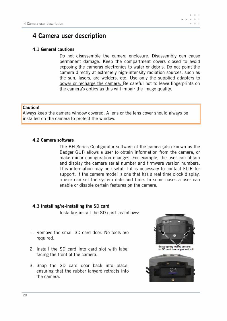
4.3 Installing/re-installing the SD card Install/re-install the SD card ias follows:
1. Remove the small SD card door. No tools arerequired.
2. Install the SD card into card slot with labelfacing the front of the camera.
3. Snap the SD card door back into place,ensuring that the rubber lanyard retracts intothe camera.
28
4.4 Installing the batteries
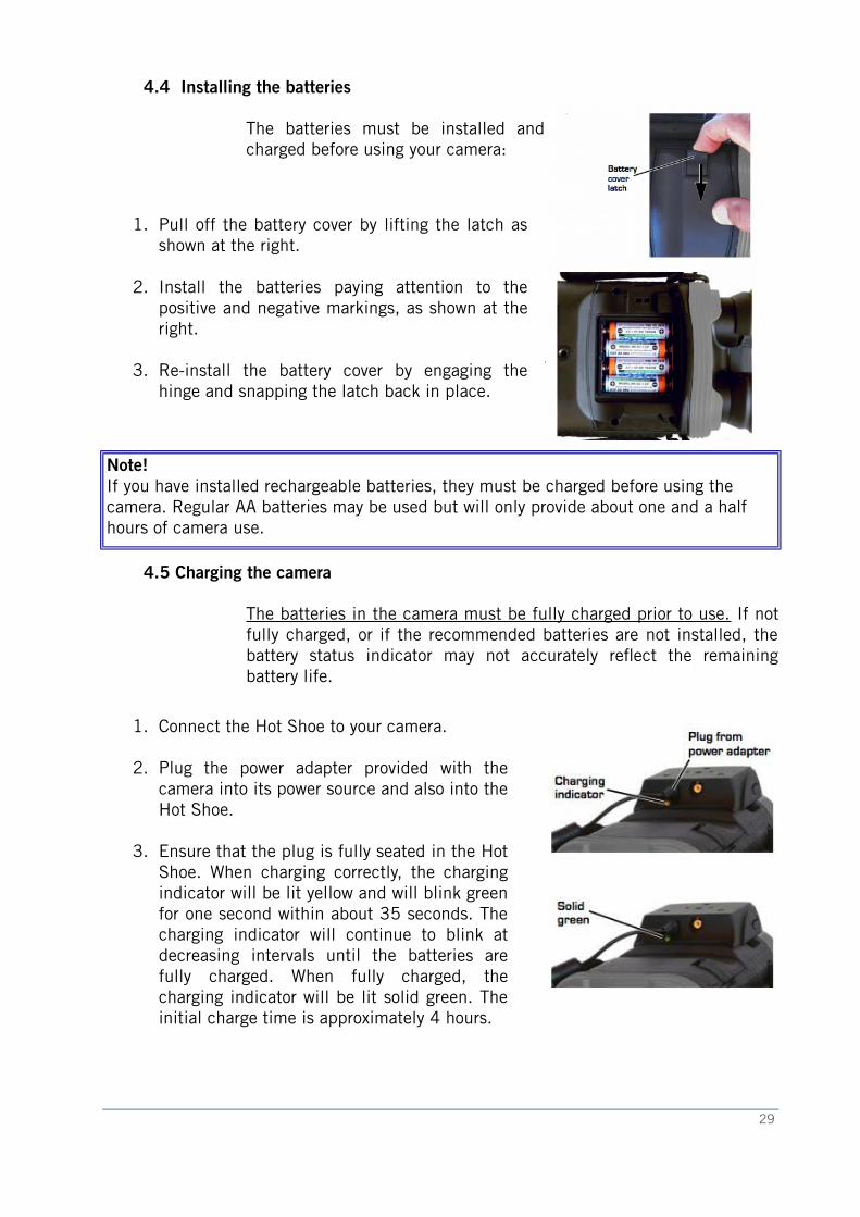
The batteries must be installed andcharged before using your camera:
1. Pull off the battery cover by lifting the latch asshown at the right.
2. Install the batteries paying attention to thepositive and negative markings, as shown at theright.
3. Re-install the battery cover by engaging thehinge and snapping the latch back in place.
Note!If you have installed rechargeable batteries, they must be charged before using the camera. Regular AA batteries may be used but will only provide about one and a half hours of camera use.
4.5 Charging the camera
The batteries in the camera must be fully charged prior to use. If notfully charged, or if the recommended batteries are not installed, thebattery status indicator may not accurately refect the remainingbattery life.
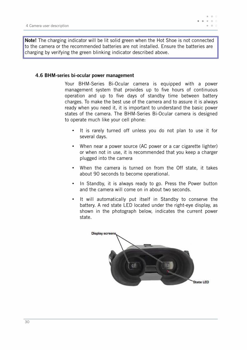
1. Connect the Hot Shoe to your camera.
2. Plug the power adapter provided with thecamera into its power source and also into theHot Shoe.
3. Ensure that the plug is fully seated in the HotShoe. When charging correctly, the chargingindicator will be lit yellow and will blink greenfor one second within about 35 seconds. Thecharging indicator will continue to blink atdecreasing intervals until the batteries arefully charged. When fully charged, thecharging indicator will be lit solid green. Theinitial charge time is approximately 4 hours.
29
4 Camera user description
Note! The charging indicator will be lit solid green when the Hot Shoe is not connected to the camera or the recommended batteries are not installed. Ensure the batteries are charging by verifying the green blinking indicator described above.
4.6 BHM-series bi-ocular power management
Your BHM-Series Bi-Ocular camera is equipped with a powermanagement system that provides up to fve hours of continuousoperation and up to fve days of standby time between batterycharges. To make the best use of the camera and to assure it is alwaysready when you need it, it is important to understand the basic powerstates of the camera. The BHM-Series Bi-Ocular camera is designedto operate much like your cell phone:
• It is rarely turned off unless you do not plan to use it forseveral days.
• When near a power source (AC power or a car cigarette lighter)or when not in use, it is recommended that you keep a chargerplugged into the camera
• When the camera is turned on from the Off state, it takesabout 90 seconds to become operational.
• In Standby, it is always ready to go. Press the Power buttonand the camera will come on in about two seconds.
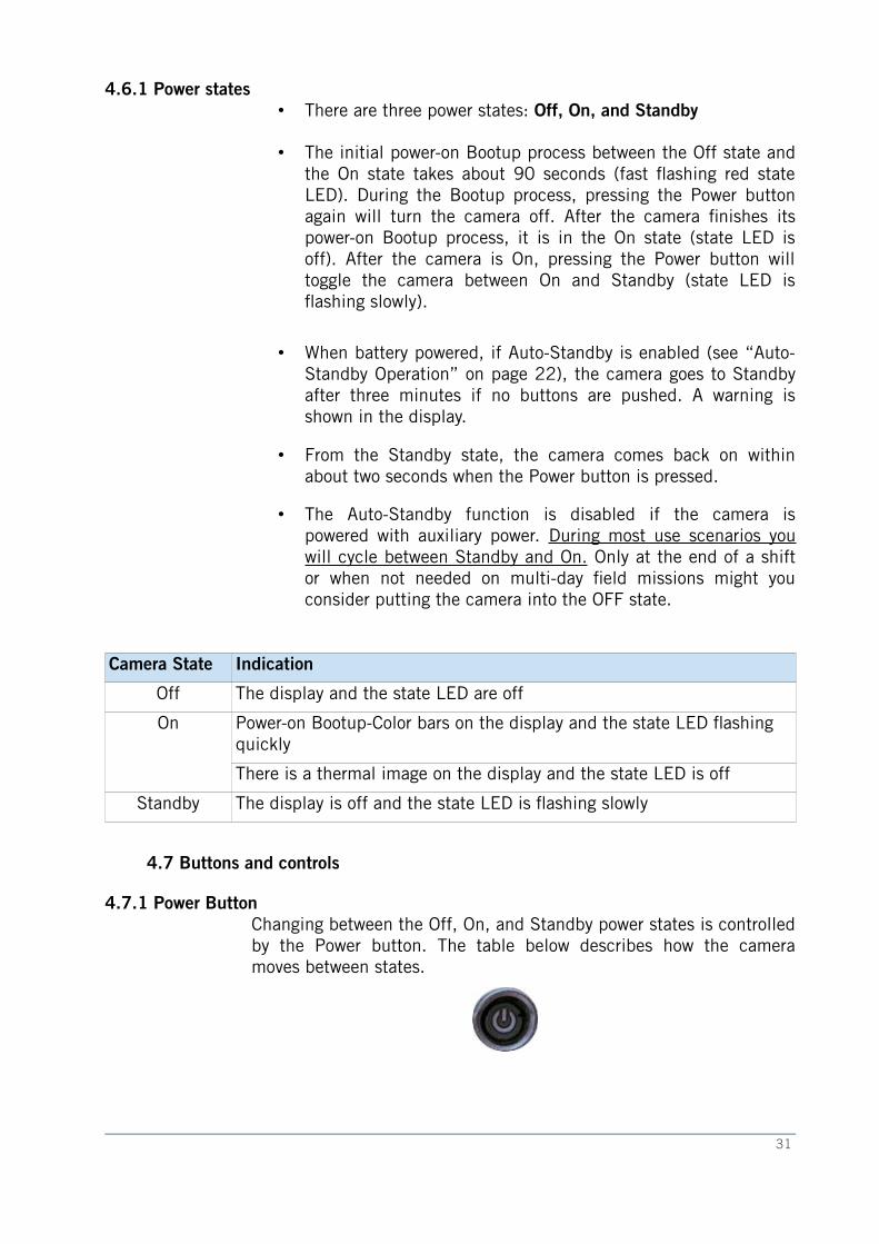
• It will automatically put itself in Standby to conserve thebattery. A red state LED located under the right-eye display, asshown in the photograph below, indicates the current powerstate.
30
4.6.1 Power states• There are three power states: Off, On, and Standby
• The initial power-on Bootup process between the Off state andthe On state takes about 90 seconds (fast fashing red stateLED). During the Bootup process, pressing the Power buttonagain will turn the camera off. After the camera fnishes itspower-on Bootup process, it is in the On state (state LED isoff). After the camera is On, pressing the Power button willtoggle the camera between On and Standby (state LED isfashing slowly).
• When battery powered, if Auto-Standby is enabled (see “Auto-Standby Operation” on page 22), the camera goes to Standbyafter three minutes if no buttons are pushed. A warning isshown in the display.
• From the Standby state, the camera comes back on withinabout two seconds when the Power button is pressed.
• The Auto-Standby function is disabled if the camera ispowered with auxiliary power. During most use scenarios youwill cycle between Standby and On. Only at the end of a shiftor when not needed on multi-day feld missions might youconsider putting the camera into the OFF state.
Camera State Indication
Off The display and the state LED are off
On Power-on Bootup-Color bars on the display and the state LED fashing quickly
There is a thermal image on the display and the state LED is off
Standby The display is off and the state LED is fashing slowly
4.7 Buttons and controls
4.7.1 Power Button Changing between the Off, On, and Standby power states is controlledby the Power button. The table below describes how the cameramoves between states.
31
4 Camera user description
From state To state Method
Off On Press the Power button for 1 second. (This will put the camera in power-on bootup for about 90 seconds before going to On.)
On Standby Momentarily press the Power button
Standby On Momentarily press the Power button
On Off Press and hold the Power button for 8 seconds
Standby Off Press and hold the Power button for 8 seconds
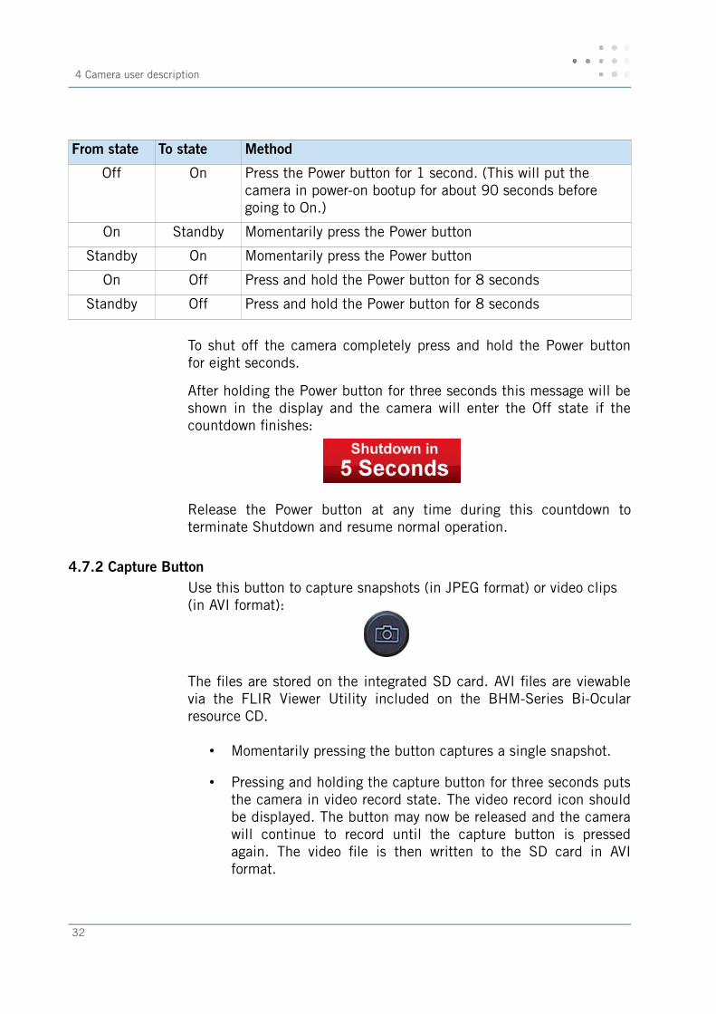
To shut off the camera completely press and hold the Power buttonfor eight seconds.
After holding the Power button for three seconds this message will beshown in the display and the camera will enter the Off state if thecountdown fnishes:
Release the Power button at any time during this countdown toterminate Shutdown and resume normal operation.
4.7.2 Capture ButtonUse this button to capture snapshots (in JPEG format) or video clips (in AVI format):
The fles are stored on the integrated SD card. AVI fles are viewablevia the FLIR Viewer Utility included on the BHM-Series Bi-Ocularresource CD.
• Momentarily pressing the button captures a single snapshot.
• Pressing and holding the capture button for three seconds putsthe camera in video record state. The video record icon shouldbe displayed. The button may now be released and the camerawill continue to record until the capture button is pressedagain. The video fle is then written to the SD card in AVIformat.
32
Twenty-fve seconds of video requires about one megabyte (MB) ofstorage on the SD card. The image and video fles must be transferredto a computer for viewing.
Note!The images must be transferred to a computer via the USB cable, or the SD card can betemporarily removed from the camera and inserted in a card reader.
• If the camera is not licensed for this feature, this messagewill be shown in the display:
• If an SD card is not installed, this message will be shown inthe display and no image will be stored:
• If the SD card is full, a warning will be shown in the displayand the image will not be stored.
Note!The stored image will include the thermal image, time and date information, and the FLIR logo. Other icons seen in the display are not stored on the saved image.
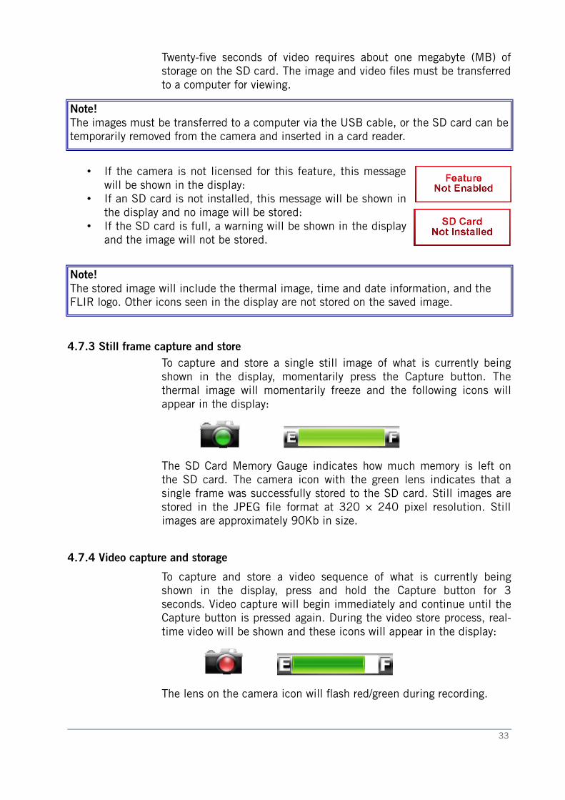
4.7.3 Still frame capture and storeTo capture and store a single still image of what is currently beingshown in the display, momentarily press the Capture button. Thethermal image will momentarily freeze and the following icons willappear in the display:
The SD Card Memory Gauge indicates how much memory is left onthe SD card. The camera icon with the green lens indicates that asingle frame was successfully stored to the SD card. Still images arestored in the JPEG fle format at 320 × 240 pixel resolution. Stillimages are approximately 90Kb in size.
4.7.4 Video capture and storage
To capture and store a video sequence of what is currently beingshown in the display, press and hold the Capture button for 3seconds. Video capture will begin immediately and continue until theCapture button is pressed again. During the video store process, real-time video will be shown and these icons will appear in the display:
The lens on the camera icon will fash red/green during recording.
33
4 Camera user description
4.7.5 Zoom Button and zoom indicatorUse this button to switch the camera between no zoom (fullresolution) and 2× zoom:
The central part of the image is magnifed twice its normal size when2× is selected. When zoom has been selected, the icon iscontinuously shown in the display:
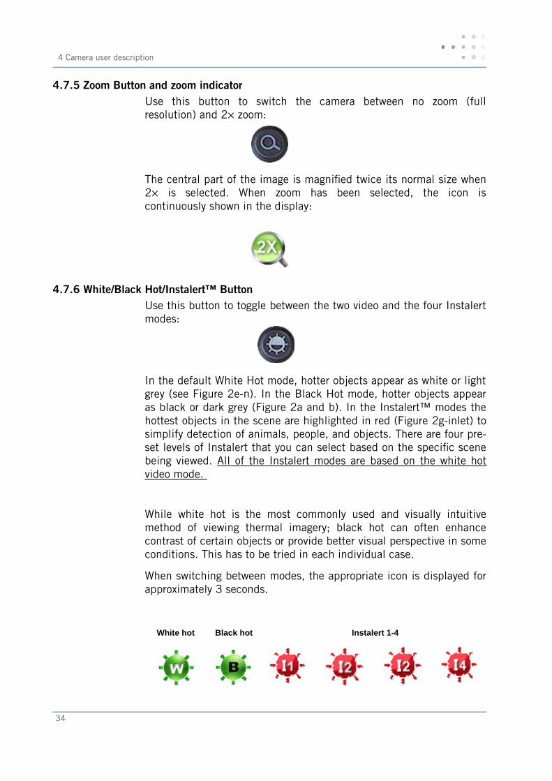
4.7.6 White/Black Hot/Instalert™ ButtonUse this button to toggle between the two video and the four Instalertmodes:
In the default White Hot mode, hotter objects appear as white or lightgrey (see Figure 2e-n). In the Black Hot mode, hotter objects appearas black or dark grey (Figure 2a and b). In the Instalert™ modes thehottest objects in the scene are highlighted in red (Figure 2g-inlet) tosimplify detection of animals, people, and objects. There are four pre-set levels of Instalert that you can select based on the specifc scenebeing viewed. All of the Instalert modes are based on the white hotvideo mode.
While white hot is the most commonly used and visually intuitivemethod of viewing thermal imagery; black hot can often enhancecontrast of certain objects or provide better visual perspective in someconditions. This has to be tried in each individual case.
When switching between modes, the appropriate icon is displayed forapproximately 3 seconds.
White hot Black hot Instalert 1-4
34
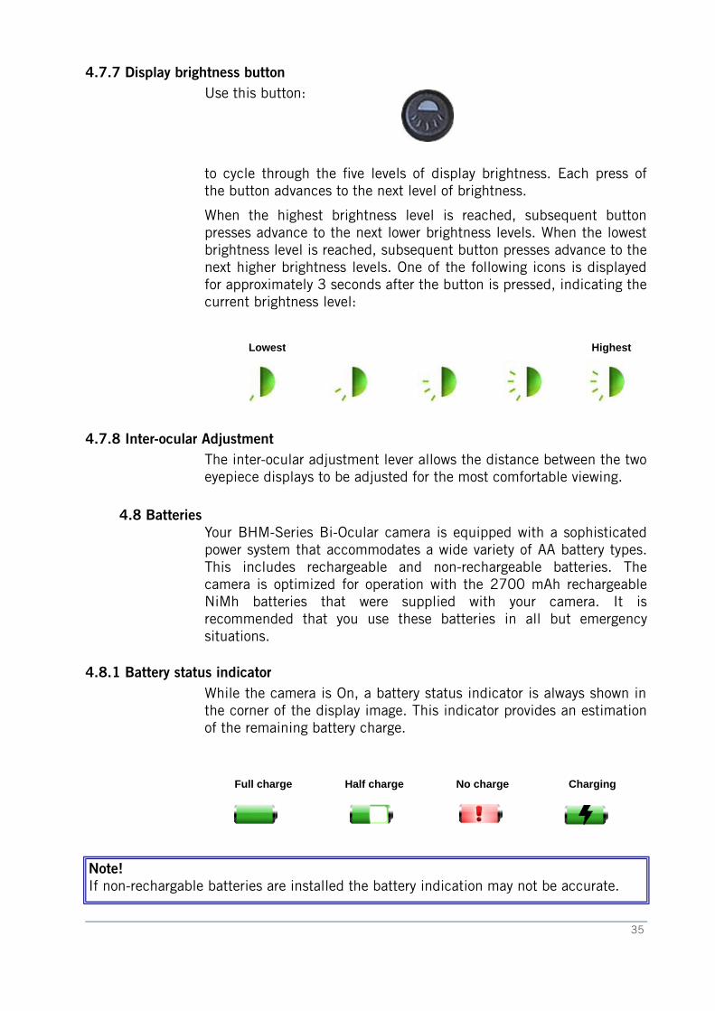
4.7.7 Display brightness buttonUse this button:
to cycle through the fve levels of display brightness. Each press ofthe button advances to the next level of brightness.
When the highest brightness level is reached, subsequent buttonpresses advance to the next lower brightness levels. When the lowestbrightness level is reached, subsequent button presses advance to thenext higher brightness levels. One of the following icons is displayedfor approximately 3 seconds after the button is pressed, indicating thecurrent brightness level:
Lowest Highest
4.7.8 Inter-ocular AdjustmentThe inter-ocular adjustment lever allows the distance between the twoeyepiece displays to be adjusted for the most comfortable viewing.
4.8 BatteriesYour BHM-Series Bi-Ocular camera is equipped with a sophisticatedpower system that accommodates a wide variety of AA battery types.This includes rechargeable and non-rechargeable batteries. Thecamera is optimized for operation with the 2700 mAh rechargeableNiMh batteries that were supplied with your camera. It isrecommended that you use these batteries in all but emergencysituations.
4.8.1 Battery status indicatorWhile the camera is On, a battery status indicator is always shown inthe corner of the display image. This indicator provides an estimationof the remaining battery charge.
Full charge Half charge No charge Charging
Note!If non-rechargable batteries are installed the battery indication may not be accurate.
35
4 Camera user description
4.8.2 Using non-rechargeable batteries
The BHM-Series Bi-Ocular camera allows Alkaline non-rechargeablebatteries to be used. When non-rechargeable batteries are installed,connecting the Hot Shoe to a power source will power the camerafrom the power source and the battery charging circuitry will bedisabled.
Note!Using Alkaline batteries, operating battery life is reduced to approximately 1.5 hours.
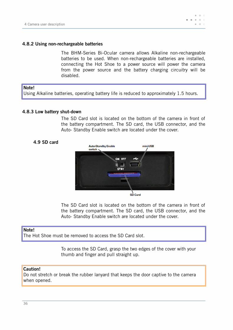
4.8.3 Low battery shut-downThe SD Card slot is located on the bottom of the camera in front ofthe battery compartment. The SD card, the USB connector, and theAuto- Standby Enable switch are located under the cover.
4.9 SD card
The SD Card slot is located on the bottom of the camera in front ofthe battery compartment. The SD card, the USB connector, and theAuto- Standby Enable switch are located under the cover.
Note!The Hot Shoe must be removed to access the SD Card slot.
To access the SD Card, grasp the two edges of the cover with your thumb and fnger and pull straight up.
Caution!Do not stretch or break the rubber lanyard that keeps the door captive to the camera when opened.
36
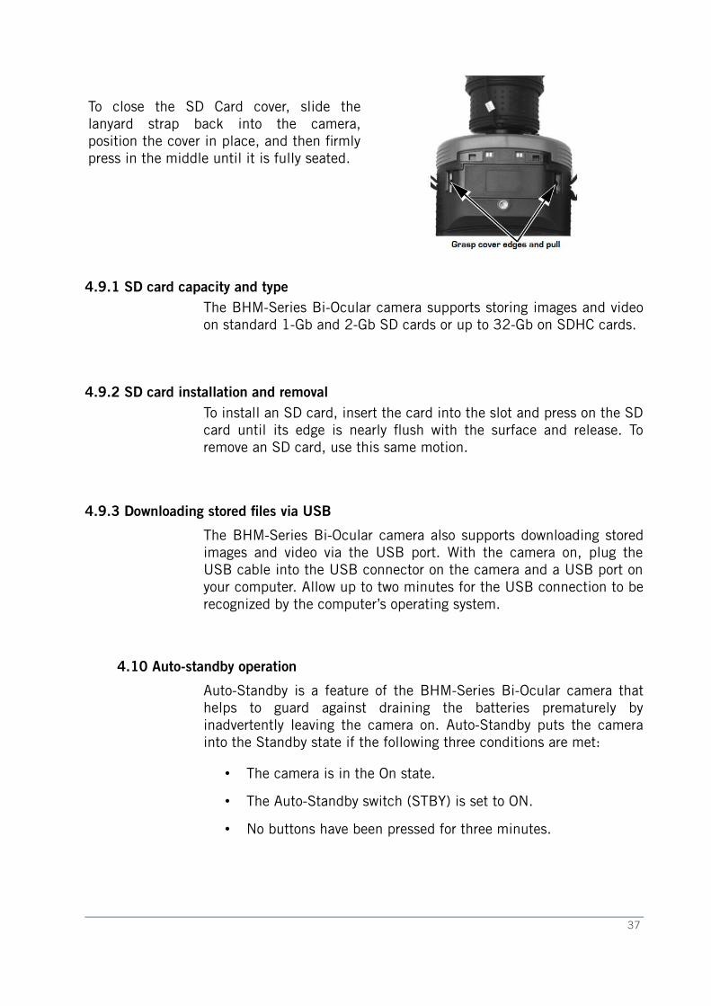
To close the SD Card cover, slide thelanyard strap back into the camera,position the cover in place, and then frmlypress in the middle until it is fully seated.
4.9.1 SD card capacity and type The BHM-Series Bi-Ocular camera supports storing images and videoon standard 1-Gb and 2-Gb SD cards or up to 32-Gb on SDHC cards.
4.9.2 SD card installation and removalTo install an SD card, insert the card into the slot and press on the SDcard until its edge is nearly fush with the surface and release. Toremove an SD card, use this same motion.
4.9.3 Downloading stored fles via USB
The BHM-Series Bi-Ocular camera also supports downloading storedimages and video via the USB port. With the camera on, plug theUSB cable into the USB connector on the camera and a USB port onyour computer. Allow up to two minutes for the USB connection to berecognized by the computer’s operating system.
4.10 Auto-standby operation
Auto-Standby is a feature of the BHM-Series Bi-Ocular camera thathelps to guard against draining the batteries prematurely byinadvertently leaving the camera on. Auto-Standby puts the camerainto the Standby state if the following three conditions are met:
• The camera is in the On state.
• The Auto-Standby switch (STBY) is set to ON.
• No buttons have been pressed for three minutes.
37
4 Camera user description
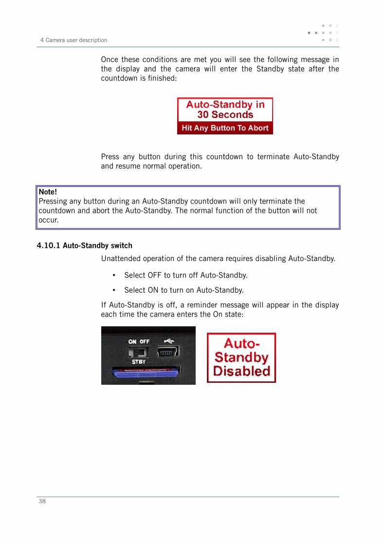
Once these conditions are met you will see the following message inthe display and the camera will enter the Standby state after thecountdown is fnished:
Press any button during this countdown to terminate Auto-Standbyand resume normal operation.
Note!Pressing any button during an Auto-Standby countdown will only terminate the countdown and abort the Auto-Standby. The normal function of the button will not occur.
4.10.1 Auto-Standby switch
Unattended operation of the camera requires disabling Auto-Standby.
• Select OFF to turn off Auto-Standby.
• Select ON to turn on Auto-Standby.
If Auto-Standby is off, a reminder message will appear in the displayeach time the camera enters the On state:
38
4.11 The hot shoe
Note!The hot shoe is not waterproof and should not be used in wet environments.
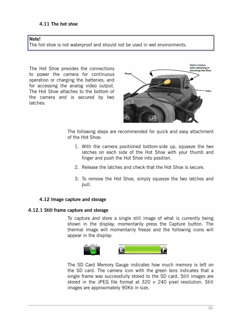
The Hot Shoe provides the connectionsto power the camera for continuousoperation or charging the batteries; andfor accessing the analog video output.The Hot Shoe attaches to the bottom ofthe camera and is secured by twolatches:
The following steps are recommended for quick and easy attachmentof the Hot Shoe:
1. With the camera positioned bottom-side up, squeeze the twolatches on each side of the Hot Shoe with your thumb andfnger and push the Hot Shoe into position.
2. Release the latches and check that the Hot Shoe is secure.
3. To remove the Hot Shoe, simply squeeze the two latches andpull.
4.12 Image capture and storage
4.12.1 Still frame capture and storage
To capture and store a single still image of what is currently beingshown in the display, momentarily press the Capture button. Thethermal image will momentarily freeze and the following icons willappear in the display:
The SD Card Memory Gauge indicates how much memory is left onthe SD card. The camera icon with the green lens indicates that asingle frame was successfully stored to the SD card. Still images arestored in the JPEG fle format at 320 × 240 pixel resolution. Stillimages are approximately 90Kb in size.
39
4 Camera user description
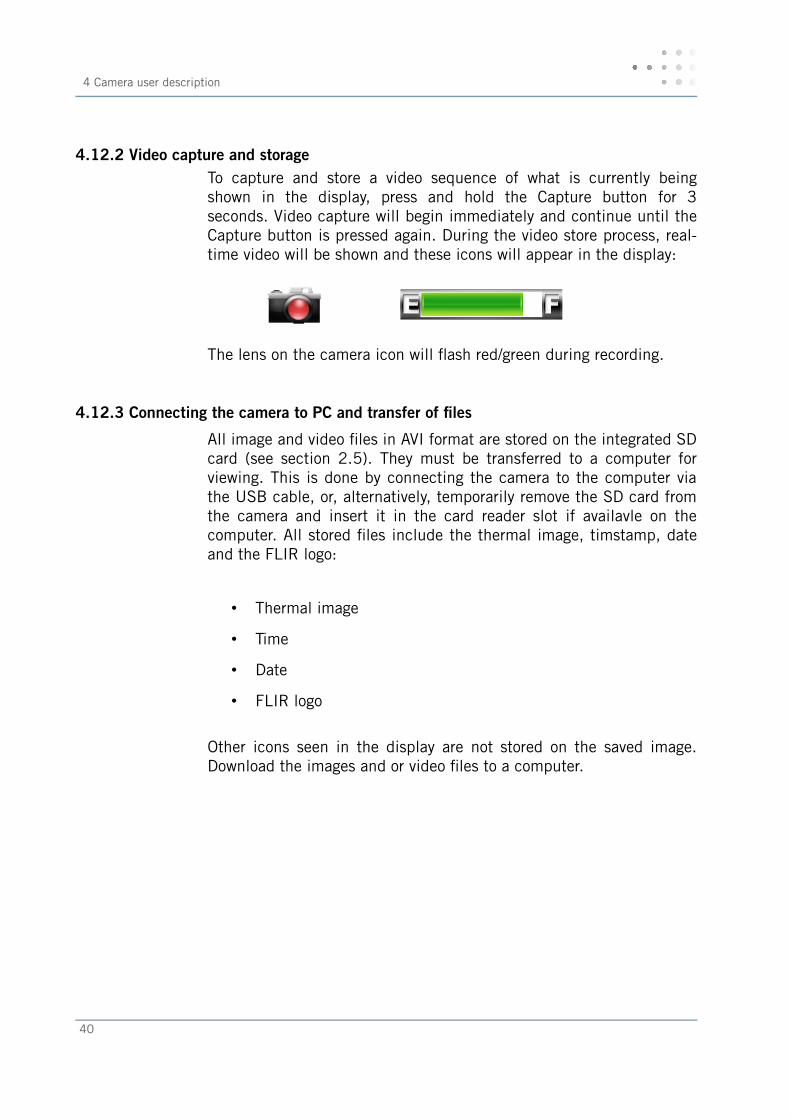
4.12.2 Video capture and storageTo capture and store a video sequence of what is currently beingshown in the display, press and hold the Capture button for 3seconds. Video capture will begin immediately and continue until theCapture button is pressed again. During the video store process, real-time video will be shown and these icons will appear in the display:
The lens on the camera icon will fash red/green during recording.
4.12.3 Connecting the camera to PC and transfer of fles
All image and video fles in AVI format are stored on the integrated SDcard (see section 2.5). They must be transferred to a computer forviewing. This is done by connecting the camera to the computer viathe USB cable, or, alternatively, temporarily remove the SD card fromthe camera and insert it in the card reader slot if availavle on thecomputer. All stored fles include the thermal image, timstamp, dateand the FLIR logo:
• Thermal image
• Time
• Date
• FLIR logo
Other icons seen in the display are not stored on the saved image.Download the images and or video fles to a computer.
40
4.13 Technical data sheet
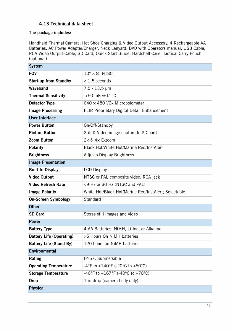
The package includes:
Handheld Thermal Camera, Hot Shoe Charging & Video Output Accessory, 4 Rechargeable AA Batteries, AC Power Adapter/Charger, Neck Lanyard, DVD with Operators manual, USB Cable, RCA Video Output Cable, SD Card, Quick Start Guide, Hardshell Case, Tactical Carry Pouch (optional)
System
FOV 10° × 8° NTSC
Start-up from Standby < 1.5 seconds
Waveband 7.5 - 13.5 µm
Thermal Sensitivity <50 mK @ f/1.0
Detector Type 640 × 480 VOx Microbolometer
Image Processing FLIR Proprietary Digital Detail Enhancement
User Interface
Power Button On/Off/Standby
Picture Button Still & Video image capture to SD card
Zoom Button 2× & 4× E-zoom
Polarity Black Hot/White Hot/Marine Red/InstAlert
Brightness Adjusts Display Brightness
Image Presentation
Built-In Display LCD Display
Video Output NTSC or PAL composite video; RCA jack
Video Refresh Rate <9 Hz or 30 Hz (NTSC and PAL)
Image Polarity White Hot/Black Hot/Marine Red/InstAlert; Selectable
On-Screen Symbology Standard
Other
SD Card Stores still images and video
Power
Battery Type 4 AA Batteries; NiMH, Li-Ion, or Alkaline
Battery Life (Operating) >5 Hours On NiMH batteries
Battery Life (Stand-By) 120 hours on NiMH batteries
Environmental
Rating IP-67, Submersible
Operating Temperature -4°F to +140°F (-20°C to +50°C)
Storage Temperature -40°F to +167°F (-40°C to +70°C)
Drop 1 m drop (camera body only)
Physical
41

4 Camera user description
Weight (incl. lens) 3.05 lb (1380 g) with batteries
Size (L x W x H) 11.5” × 6.5” × 2.6”
Range Performance
Detect Man (1.8 m × 0.5 m)
~2.2 km
Detect Small Vessel (2.3 m× 2.3 m)
~6.5 km
42