Embed Size (px)
Citation preview

Pressure Vessel Engineering Ltd.Finite Element Analysis ASME Code Calculations
Canadian Vessel Registration Vessel Modeling and Drafting
ASME VIII-1 Section UW-11 & UG-116(e)ASME Sample L-1.6.3 Project
Left Head: [Category A] - long seam weld in head, not head to shell weldFlat UW12 Column for this weld #VALUE!
Seamless UW12 Column for joining circ weld #VALUE!
Seamless Weld type number #VALUE!
UW-11(a) is met Isolated long seam efficiency #VALUE!
Allowed UW12 column #VALUE!
#VALUE! ###
Left Circ Weld: [Category A, B, C or D] head to shell weldCorner UW12 column for this weld #VALUE!
None Circ seam type number #VALUE!
#VALUE!
Body Long Seam: [Category A]Smls or ERW UW12 column for the body long seam #VALUE!
Seamless UW12 column for left circ weld #VALUE!
UW-11(a) is met UW12 column for right circ weld #VALUE!
Long seam type number #VALUE!
#VALUE! left circ efficiency #VALUE! Isolated long seam efficiency #VALUE!
right circ efficiency #VALUE! Allowed UW12 column #VALUE!
#VALUE! ###
Right Circ Weld: [Category A, B, C or D] head to shell weldDouble_Fillet UW12 column #VALUE!
None Circ seam type number #VALUE!
#VALUE!
Right Head: [Category A] - long seam weld in head, not head to shell weldSemi-Elliptical UW12 column for this weld #VALUE!
Seamless UW12 Column for joining circ weld #VALUE!
Seamless Weld type number #VALUE!
UW-11(a) is met Isolated long seam efficiency #VALUE!
Allowed UW12 column #VALUE!
#VALUE! ###
Notes: Sketch:RT1
######
#VALUE!
#VALUE!
#VALUE!
Comments:This sheet is for educational use only. Only ASME can make code interpretations.UW-11(a) and UW-11(a)(5)(b) Complience is optional.ERW Pipe - start calculations with stress values from IID that INCLUDE the 0.85 long seam efficiency, then run the code calculations with the additional long and circ seam efficiency shown here - refer to UW-12(e).
Pressure Vessel Engineering Ltd.120 Randall Drive, Suite B
Waterloo, Ontario, Canada, N2V 1C6
Vessel Weld Efficiency ver 2.10
Left head Left head weld type Left head weld radiography
Allowed head longitudinal efficiency
Left head to body circ-weld type Left head to body circ-weld radiography
Left circ weld efficiency
Body long weld type Body long-weld radiography
Allowed circ efficiency Allowed long seam efficiency
Right head to body circ-weld type Right head to body circ-weld radiography
Right circ weld efficiency
Right head Right head weld type Right head weld radiography
Allowed head longitudinal efficiency
www.pveng.com (519) 880-9808

1 Pressure Vessel Engineering Ltd.2 Finite Element Analysis ASME Code Calculations3 Canadian Vessel Registration Vessel Modeling and Drafting
4 Page 1 of 15 Conical Section Description
6 Dimensions:7 12.0008 8.0009 0.25010 12.00011 0.010
12 Material and Conditions:13 SA-240 304 Material 14 20,00015 1.0016 50.0
17 Calculated Properties:18 Approx. cone weight based on steel, lbs = 26.419 Approx. cone volume , cuft = 0.5020 ATAN((12-8)/(2*12)) = 0.16521 DEGREES(0.165) = 9.46222 0.25-0.01 = 0.240
23
24
25 50*12/(2*COS(0.165)*(20000*1+0.4*50)) + 0.01 = 0.02526 Treq <= t 0.025 <= 0.25 = Acceptable
27
28
29 2*20000*1*0.24*COS(0.165)/(12-0.8*0.24*COS(0.165)) = 801.830 Pmax >= P 801.8 >= 50 = Acceptable
31 T provides a worst case required thickness for nozzle analysis for a nozzle located on the large end of the cone and located
32 on the long seam weld.
33 The UG-16(b) minimum thickness requirement has not been taken into consideration here.
34 Discontinuity checks which are required for each end of the cone when it is welded to a straight shell are not included
35 in this sheet.
36 This sheet cannot be used to check for allowable exterior pressure loads.
37 This sheet is for educational use only - use at your own risk.
38 Pressure Vessel Engineering Ltd.39 120 Randall Drive, Suite B40 Waterloo, Ontario, Canada, N2V 1C641
Cone Design Tool ver E4.02
ODL [in] - outside diameter of large end ODS [in] - outside diameter of small end t [in] - thickness L [in] -length Corr [in] - corrosion allowance
S [psi] - allowable stress E - long seam efficiency P [psi] - interior pressure
a [rad] = ATAN((ODL-ODS)/(2*L)) ~~ alpha angle in radians
angle [deg] = Degrees(a) ~~ alpha angle in degrees
nt [in] = t-Corr ~~ thickness with corrosion allowance removed
Required Thickness: VIII-1 App 1-4 e)
Treq [in] = P*ODL/(2*COS(a)*(S*E+0.4*P)) + Corr ~~required minimum thickness
CheckTreq =
Maximum Pressure: VIII-1 App 1-4(e)
Pmax [psi] = 2*S*E*nt*cos(a)/(ODL-0.8*nt*cos(a)) ~~maximum allowed design pressure
CheckPMax =
www.pveng.com (519) 880-9808
P
LnLength
ODL
t
ODS

1 Pressure Vessel Engineering Ltd.2 Finite Element Analysis ASME Code Calculations3 Canadian Vessel Registration Vessel Modeling and Drafting
4 Page 1 of 1
5 Cone Inputs:6 Sample Cone Description7 24.008 12.009 5.00010 0.25011
12
13
14
15
16 Calculated Variables:17 ((LOD-2*t)-SOD)/2 ((24-2*0.25)-12)/2 = 5.75018 ATAN(Y/L) ATAN(5.75/5) = 0.85519 SQRT(Y^2+L^2) SQRT(5.75^2+5^2) = 7.62020 SQRT(BL^2+t^2) SQRT(7.62^2+0.25^2) = 7.62421 ATAN(t/DL) ATAN(0.25/7.624) = 0.03322 Degrees(G+B) DEGREES(0.033+0.855) = 50.923 (t*cos(Radians(GB)))/2 (0.25*COS(RADIANS(50.9)))/2 = 0.07924 (LOD-2*t)/2+Y2 (24-2*0.25)/2+0.079 = 11.82925 SOD/2-Y2 12/2-0.079 = 5.921
26 Layout Dimensions:27 DDI/(sin(Radians(GB))) 5.921/(SIN(RADIANS(50.9))) = 7.63328 DDO/(sin(Radians(GB))) 11.829/(SIN(RADIANS(50.9))) = 15.24929 (DDI/Ri)*360 (5.921/7.633)*360 = 279.254
30 Comments:31 - This program calculates thickness corrected cones where
32 the inside of the large end of the cone touches the inside
33 of the large pipe and where the outside of the small end of the
34 cone touches the outside of the small pipe.
35 - Ri, Ro and all lines share the same origin.
36 - The prebend tabs shown here are used for some pyramid
37 rollers if required.
38 - If a brake press is used to bend the cone, then all bend lines
39 should pass through the origin.
40 - This program assumes that the large pipe has the same thickness as the cone. The thickness of the small pipe is ignored.
41 - Adjust the length of the cone if required to get the desired cone angle GB.
42 - This program is intended for educational use only. Pressure Vessel Engineering Ltd. Is not responsible for its use.
43 Pressure Vessel Engineering Ltd.44 120 Randall Drive, Suite B45 Waterloo, Ontario, Canada, N2V 1C646
Cone Layout Tool ver E4.02
LOD [in] - OD of the large pipe SOD [in] - OD of the small pipe L [in] - cone length t [in] - cone and large pipe thickness
Y [in] =B [rad] =BL [in] =DL [in] =G [rad] =
GB [deg] =Y2 [in] =
DDO [in] =DDI [in] =
Ri [in] =Ro [in] =
Theta [deg] =
www.pveng.com (519) 880-9808
L
SOD
LOD
tGB
Theta
Ro
Ri
BendLines
OriginPre-bend
1
2 Pressure Vessel Engineering Ltd.3 Finite Element Analysis ASME Code Calculations4 Canadian Vessel Registration Vessel Modeling and Drafting5
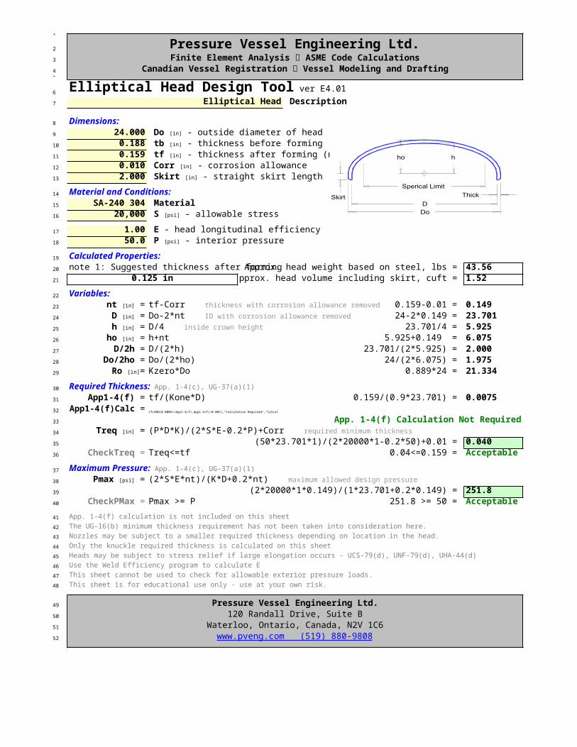
6 Page 1 of 17 Elliptical Head Description
8 Dimensions:9 24.00010 0.18811 0.15912 0.01013 2.000
14 Material and Conditions:15 SA-240 304 Material 16 20,000
17 1.0018 50.0
19 Calculated Properties:20 note 1: Suggested thickness after forming Approx. head weight based on steel, lbs = 43.5621 0.125 in Approx. head volume including skirt, cuft = 1.52
22 Variables:23 0.159-0.01 = 0.14924 24-2*0.149 = 23.70125 23.701/4 = 5.92526 5.925+0.149 = 6.07527 D/(2*h) 23.701/(2*5.925) = 2.00028 Do/(2*ho) 24/(2*6.075) = 1.97529 Kzero*Do 0.889*24 = 21.334
30
31 tf/(Kone*D) 0.159/(0.9*23.701) = 0.007532 if(AND(0.0005=<App1-4(f),App1-4(f)<0.002),"Calculation Required","Calculation not required")
33 App. 1-4(f) Calculation Not Required34
35 (50*23.701*1)/(2*20000*1-0.2*50)+0.01 = 0.04036 Treq<=tf 0.04<=0.159 = Acceptable
37
38
39 (2*20000*1*0.149)/(1*23.701+0.2*0.149) = 251.840 Pmax >= P 251.8 >= 50 = Acceptable
41 App. 1-4(f) calculation is not included on this sheet
42 The UG-16(b) minimum thickness requirement has not been taken into consideration here.
43 Nozzles may be subject to a smaller required thickness depending on location in the head.
44 Only the knuckle required thickness is calculated on this sheet
45 Heads may be subject to stress relief if large elongation occurs - UCS-79(d), UNF-79(d), UHA-44(d)
46 Use the Weld Efficiency program to calculate E
47 This sheet cannot be used to check for allowable exterior pressure loads.
48 This sheet is for educational use only - use at your own risk.
49 Pressure Vessel Engineering Ltd.50 120 Randall Drive, Suite B51 Waterloo, Ontario, Canada, N2V 1C652
Elliptical Head Design Tool ver E4.01
Do [in] - outside diameter of head tb [in] - thickness before forming tf [in] - thickness after forming (note 1) Corr [in] - corrosion allowance Skirt [in] - straight skirt length
S [psi] - allowable stress
E - head longitudinal efficiency P [psi] - interior pressure
nt [in] = tf-Corr ~~ thickness with corrosion allowance removed
D [in] = Do-2*nt ~~ ID with corrosion allowance removed
h [in] = D/4 ~~ inside crown height
ho [in] = h+nt D/2h =
Do/2ho =Ro [in]=
Required Thickness: App. 1-4(c), UG-37(a)(1)
App1-4(f) =App1-4(f)Calc =
Treq [in] = (P*D*K)/(2*S*E-0.2*P)+Corr ~~ required minimum thickness
CheckTreq =
Maximum Pressure: App. 1-4(c), UG-37(a)(1)
Pmax [psi] = (2*S*E*nt)/(K*D+0.2*nt) ~~ maximum allowed design pressure
CheckPMax =
www.pveng.com (519) 880-9808

1
2 Pressure Vessel Engineering Ltd.3 Finite Element Analysis ASME Code Calculations4 Canadian Vessel Registration Vessel Modeling and Drafting5
6 Page 1 of 17 F&D Head Description
8 Dimensions:9 24.00010 24.00011 1.44012 0.18813 0.15914 0.01015 2.000
16 Material and Conditions:17 SA-240 304 Material 18 20,000
19 0.8520 50.0
21 Calculated Properties:22 note 1:Suggested radius L per UG-32(j) 24.00 Approx. head weight based on steel, lbs = 38.5323 note 2:Suggested radius IKR per UG-32(j) 1.440 Approx. head volume including skirt, cuft = 1.1224 note 3:Suggested thickness after forming 0.1555
25 Variables:26 0.159-0.01 = 0.14927 24-2*0.149 = 23.70128 L/IKR 24/1.44 = 16.66729 0.25*(3+sqrt(L/IKR)) 0.25*(3+SQRT(24/1.44)) = 1.77130 24+0.188 = 24.188
31
32 tf/L 0.159/24 = 0.00733 if(AND(0.0005=<App1-4(f),App1-4(f)<0.002),"Calculation Required","Calculation not required")
34 App. 1-4(f) Calculation Not Required35
36 (50*24*1.771)/(2*20000*0.85-0.2*50)+0.01 = 0.07337 Treq<=tf 0.073<=0.159 = Acceptable
38
39
40 (2*20000*0.85*0.149)/(24*1.771+0.2*0.149) = 119.441 Pmax >= P 119.4 >= 50 = Acceptable
42 App. 1-4(f) calculation is not included on this sheet
43 Nozzles may be subject to a smaller required thickness depending on location in the head.
44 Only the knuckle required thickness is calculated on this sheet
45 Heads may be subject to stress relief if large elongation occurs - UCS-79(d), UNF-79(d), UG-37(a)(1)
46 The UG-16(b) minimum thickness requirement has not been taken into consideration here.
47 This sheet cannot be used to check for allowable exterior pressure loads.
48 Use the Weld Efficiency program to calculate E
49 This sheet is for educational use only - use at your own risk.
50 Pressure Vessel Engineering Ltd.51 120 Randall Drive, Suite B52 Waterloo, Ontario, Canada, N2V 1C653
F&D Head Design Tool ver E4.01
Do [in] - outside diameter of head L [in] - inside crown radius (note 1) IKR [in] - inside knuckle radius (note 2) tb [in] - thickness before forming tf [in] - thickness after forming (note 3) Corr [in] - corrosion allowance Skirt [in] - straight skirt length
S [psi] - allowable stress
E - head longitudinal efficiency P [psi] - interior pressure
nt [in] = tf-Corr ~~ thickness with corrosion allowance removed
D [in] = Do-2*nt ~~ ID with corrosion allowance removed
L/r =M =
Ro [in] = L+tb
Required Thickness: App. 1-4(a), App. 1-4(d)
App1-4(f) =App1-4(f)Calc =
Treq [in] = (P*L*M)/(2*S*E-0.2*P)+Corr ~~ required minimum thickness
CheckTreq =
Maximum Pressure: App. 1-4(a), App. 1-4(d)
Pmax [psi] = (2*S*E*nt)/(L*M+0.2*nt) ~~ maximum allowed design pressure
CheckPMax =
www.pveng.com (519) 880-9808

1
2 Pressure Vessel Engineering Ltd.3 Finite Element Analysis ASME Code Calculations4 Canadian Vessel Registration Vessel Modeling and Drafting5
6 Page 1 of 17 Hemispherical Head Description
8 Dimensions:9 24.00010 0.18811 0.15912 0.010
13 Material and Conditions:14 SA-240 304 Material 15 20,000
16 1.0017 50.0
18 Calculated Properties:19 Approx. head weight based on steel, lbs = 47.420 Approx. head volume, cuft = 2.01
21 Variables:22 0.159-0.01 = 0.14923 (24-2*0.149)/2 = 11.85124 Do/2 24/2 = 12.000
25
26
27 (50*11.851)/(2*20000*1-0.2*50)+0.01 = 0.02528 Treq<=tf 0.025<=0.159 = Acceptable
29
30
31 (2*20000*1*0.149)/(11.851+0.2*0.149) = 502.932 Pmax >= P 502.9 >= 50 = Acceptable
33 App. 1-4(f) calculation is not included on this sheet
34 Heads may be subject to stress relief if large elongation occurs - UCS-79(d), UNF-79(d), UHA-44(d)
35 Use the Weld Efficiency program to calculate E
36 The UG-16(b) minimum thickness requirement has not been taken into consideration here.
37 This sheet cannot be used to check for allowable exterior pressure loads.
38 This sheet is for educational use only - use at your own risk.
39 Pressure Vessel Engineering Ltd.40 120 Randall Drive, Suite B41 Waterloo, Ontario, Canada, N2V 1C642
Hemispherical Head Design Tool ver E4.01
Do [in] - outside diameter of head tb [in] - thickness before forming tf [in] - thickness after forming Corr [in] - corrosion allowance
S [psi] - allowable stress
E - head longitudinal efficiency P [psi] - interior pressure
nt [in] = tf-Corr ~~ thickness with corrosion allowance removed
L [in] = (Do-2*nt)/2 ~~ inside radius with corrosion allowance removed
Ro [in]=
Required Thickness: UG-32(f)
Treq [in] = (P*L)/(2*S*E-0.2*P)+Corr ~~required minimum thickness
CheckTreq =
Maximum Pressure: UG-32(f)
Pmax [psi] = (2*S*E*nt)/(L+0.2*nt) ~~ maximum allowed design pressure
CheckPMax =
www.pveng.com (519) 880-9808

1
2 Pressure Vessel Engineering Ltd.3 Finite Element Analysis ASME Code Calculations4 Canadian Vessel Registration Vessel Modeling and Drafting5
6 Page 1 of 17 Straight Pipe and Shell Description
8 Dimensions:9 24.00010 0.25011 12.00012 0.010
13 Material and Conditions:14 SA-240 304 Material 15 20,000
16 0.8517 0.7018 12.5%19 50.0
20 Calculated Properties:21 ((Do/2-t)^2)*pi()*L/1728 ((24/2-0.25)^2)*PI()*12/1728 = 3.0122 (Do-t)*pi()*L*t*40.84/144 (24-0.25)*PI()*12*0.25*40.84/144 = 63.48
23 Variables:24 t*UTP 0.25*0.1 = 0.03125 t-Corr-UT 0.25-0.01-0.031 = 0.20926 Do/2-nt 24/2-0.209 = 11.791
27
28 50*11.791/(20000*0.85-0.6*50) = 0.03529 50*11.791/(2*20000*0.7+0.4*50) = 0.02130 MAX(0.035,0.021) = 0.03531 Treq <= nt 0.035 <= 0.209 = Acceptable
32
33 (S*El*nt)/(Ri+0.6*nt) (20000*0.85*0.209)/(11.791+0.6*0.209) = 29834 (2*S*Ec*nt)/(Ri-0.4*nt) (2*20000*0.7*0.209)/(11.791-0.4*0.209) = 49935 MIN(298,499) = 297.836 PMax >= P 297.8 >= 50 = Acceptable
37 Treq provides a worst case required thickness for nozzle analysis for a nozzle located on the long seam or circ seam
38 This sheet will not calculate thick walled vessels Not a thick walled vessel, calculations are valid
39 The UG-16(b) minimum thickness requirement has not been taken into consideration here.
40 This sheet cannot be used to check for allowable exterior pressure loads.
41 Use the Weld Efficiency program to calculate El and Ec
42 This sheet is for educational use only - use at your own risk.
43 Pressure Vessel Engineering Ltd.44 120 Randall Drive, Suite B45 Waterloo, Ontario, Canada, N2V 1C646
Pipe and Shell Design Tool ver E4.02
Do [in] - outside diameter t [in] - nominal wall thickness L [in] -length Corr [in] - corrosion allowance
S [psi] - allowable stress
El - long seam efficiency (circ stress) Ec - circ seam efficiency (long stress) UTP [%] - undertolerance allowance P [psi] - interior pressure
Volume [cuft] = Weight [lb] =
UT [in] = nt [in] = Ri [in] =
Required Thickness: UG-27(c)(1,2)
ta [in] = P*Ri/(S*El-0.6*P) ~~ long sem
tb [in] = P*Ri/(2*S*Ec+0.4*P) ~~ circ seam
Treq [in] = MAX(ta,tb) ~~ required minimum thickness
CheckTreq =
Maximum Pressure: UG-27(c)(1,2)
Pint1 [psi] = Pint2 [psi] = PMax [psi] = Min(Pint1,Pint2) ~~ maximum allowed design pressure
CheckP =
Check →
www.pveng.com (519) 880-9808
t
Do
Leng
th
Long
Sea
m

1
2 Pressure Vessel Engineering Ltd.3 Finite Element Analysis ASME Code Calculations4 Canadian Vessel Registration Vessel Modeling and Drafting5
6 Page 1 of 27 Nozzle Description
8 Shell Inputs:9 SA-240 304 Material 10 20,00011 1.00
12 24.00013 0.20414 0.12515 0.015
16 Nozzle Inputs:17 SA-312 304 Material 18 20,00019 1.00
20 4.00021 0.16022 1.00023 1.00024 0.01525 12.5%26 150.0
27 0.50028 0.500
29 Variables:30 Nwall*UTP 0.16*0.1 = 0.02031 Do/2 - (Nwall-nca) + UT 4/2 - (0.16-0.015) + 0.02 = 1.87532 Nwall-nca 0.16-0.015 = 0.14533 Nwall-2*nca 0.16-2*0.015 = 0.13034 Do-2*tn 4-2*0.145 = 3.71035 MIN(Ip-sca,2.5*nt,2.5*ti) MIN(1-0.015,2.5*0.204,2.5*0.13) = 0.32536 MIN(Sn/Sv,1) MIN(20000/20000,1) = 1.00037 MIN(Sn/Sv,1) MIN(20000/20000,1) = 1.000
38
39
40 (150*1.875)/(20000*1 - 0.6*150)+0.015 = 0.02941 TreqN <= Nwall 0.029 <= 0.16 = Acceptable
42 Minimum thickness per UG-45 [in] = Acceptable 0.140
43
44
45 1*3.71*0.125*1+2*0.145*0.125*1*(1-1) = 0.46446 max(d, 2*(nt+tn))*(E1*nt-1*Treq)-2*tn*(E1*nt-1*Treq)*(1-fr1)47 MAX(3.71, 2*(0.204+0.145))*(1*0.204-1*0.125)-2*0.145*(1*0.204-1*0.125)*(1-1) = 0.29348 min((tn-trnR)*fr2*Min(5*nt,2*Lp) , (tn-trnR)*fr2*Min(5*tn,2*Lp))49 MIN((0.145-0.014)*1*MIN(5*0.204,2*1) , (0.145-0.014)*1*MIN(5*0.145,2*1)) = 0.09550 Min(5*nt*ti*fr2,5*ti*ti*fr2,2*h*ti*fr2)51 MIN(5*0.204*0.13*1,5*0.13*0.13*1,2*0.325*0.13*1) = 0.085
Nozzle Design Tool ver E4.01
Sv [psi] - allowable stress E1 - efficiency of shell at nozzle
Ds [in] - inside diameter of shell nt [in] - nominal shell wall thickness Treq [in] - required shell wall thickness sca [in] - head or shell corrosion allowance
Sn [psi] - allowable stress E - nozzle efficiency
Do [in] - outside diameter of nozzle Nwall [in] - nominal wall thickness of nozzle Lp [in] - exterior projection of nozzle Ip [in] - interior projection of nozzle nca [in] - nozzle corrosion allowance UTP [%] - undertolerance allowance Pn [psi] - interior pressure
Leg41 [in] - fillet size Leg43 [in] - fillet size
UT [in] = Rn [in] = tn [in] = ti [in] = d [in] = h [in] = fr1 = fr2 =
Required Thickness: UG-27(c)(1,2)
TreqN [in] = (Pn*Rn)/(Sn*E - 0.6*Pn)+nca ~~ required minimum thickness
CheckTreqN =
Area Replacement: Ar [in^2] = 1*d*Treq*1+2*tn*Treq*1*(1-fr1) ~~ required Area
A1 [in^2] =
A2 [in^2] =
A3 [in^2] =

1 Leg41^2*fr2 0.5^2*1 = 0.2502 (Leg43-nca)^2*fr2 (0.5-0.015)^2*1 = 0.2353 0.293+0.095+0.085+0.25+0.235 = 0.9584 0.958 >= 0.464 = Acceptable
5 The UG-16(b) minimum thickness requirement has not been taken into consideration here.
6 The required weld size is not checked on this sheet
7 This sheet cannot be used to check for allowable exterior pressure loads.
8 This sheet is for educational use only - use at your own risk.
9 Pressure Vessel Engineering Ltd.10 120 Randall Drive, Suite B11 Waterloo, Ontario, Canada, N2V 1C612
A41 [in^2] = A43 [in^2] =
Aa [in^2] = A1+A2+A3+A41+A43 ~~ actual area
CheckA = Aa >= Ar ~~ check area replacement
www.pveng.com (519) 880-9808

1
2 Pressure Vessel Engineering Ltd.3 Finite Element Analysis ASME Code Calculations4 Canadian Vessel Registration Vessel Modeling and Drafting5
6 Page 1 of 27 Nozzle Description
8 Shell Inputs:9 SA-240 304 Material 10 20,00011 1.00
12 24.00013 0.20414 0.01515 0.015
16 Nozzle Inputs:17 SA-312 304 Material 18 20,00019 1.00
20 4.00021 0.16022 1.00023 1.00024 0.01525 12.5%26 50.0
27 Reinforcement:28 SA-240 304 Material 29 20,00030 0.25031 6.00032 0.20033 0.20034 0.20035 0.250
36 Variables:37 Nwall*UTP 0.16*0.1 = 0.02038 Do/2 - (Nwall-nca) + UT 4/2 - (0.16-0.015) + 0.02 = 1.87539 Nwall-2*nca 0.16-2*0.015 = 0.13040 MIN(Ip-sca,2.5*nt,2.5*ti) MIN(1-0.015,2.5*0.204,2.5*0.13) = 0.32541 Nwall-nca 0.16-0.015 = 0.14542 Do-2*tn 4-2*0.145 = 3.710
43
44
45 (50*1.875)/(20000*1 - 0.6*50)+0.015 = 0.02046 TreqN <= Nwall 0.02 <= 0.16 = Acceptable
47 Minimum thickness per UG-45 [in] = Acceptable 0.078
Nozzle and Repad Design Tool ver E4.01
Sv [psi] - allowable stress E1 - efficiency of shell at nozzle
Ds [in] - inside diameter of shell nt [in] - nominal shell wall thickness Treq [in] - required shell wall thickness sca [in] - shell corrosion allowance
Sn [psi] - allowable stress E - nozzle efficiency
Do [in] - outside diameter of nozzle Nwall [in] - nominal wall thickness of nozzle Lp [in] - exterior projection of nozzle Ip [in] - interior projection of nozzle nca [in] - nozzle corrosion allowance UTP [%] - undertolerance allowance Pn [psi] - interior pressure
Sp [psi] - allowable stress of repad te [in] - repad thickness Dp [in] - outside diameter Leg41 [in] - fillet size Leg42 [in] - fillet size Leg43 [in] - fillet size LegG [in] - depth of groove
UT [in] = Rn [in] =
ti [in] = h [in] =
tn [in] = d [in] =
Required Thickness: UG-27(c)(1,2)
TreqN [in] = (Pn*Rn)/(Sn*E - 0.6*Pn)+nca ~~ required minimum thickness
CheckTreqN =

1
2
3 1*3.71*0.015*1+2*0.145*0.015*1*(1-1) = 0.0564 max(d, 2*(nt+tn)) * (E1*nt-1*Treq)-2*tn*(E1*nt-1*Treq)*(1-fr1)5 MAX(3.71, 2*(0.204+0.145)) * (1*0.204-1*0.015)-2*0.145*(1*0.204-1*0.015)*(1-1) = 0.7016 min((tn-trnR)*fr2*min(5*nt,2*Lp),(tn-trnR)*(Min(2.5*tn+te,2*Lp)*fr2*2))7 MIN((0.145-0.005)*1*MIN(5*0.204,2*1),(0.145-0.005)*(MIN(2.5*0.145+0.25,2*1)*1*2)) = 0.1438 Min(5*nt*ti*fr2,5*ti*ti*fr2,2*h*ti*fr2)9 MIN(5*0.204*0.13*1,5*0.13*0.13*1,2*0.325*0.13*1) = 0.08510 (Dp-d-2*tn)*te*fr4 (6-3.71-2*0.145)*0.25*1 = 0.50011 Leg41^2*fr3 0.2^2*1 = 0.04012 Leg42^2*fr4 0.2^2*1 = 0.04013 (Leg43-nca)^2*fr2 (0.2-0.015)^2*1 = 0.03414
15 0.701+0.143+0.085+0.5+0.04+0.04+0.034 = 1.54316 1.543 >= 0.056 = Acceptable
17 The UG-16(b) minimum thickness requirement has not been taken into consideration here.
18 The required weld size is not checked on this sheet
19 This sheet cannot be used to check for allowable exterior pressure loads.
20 This sheet is for educational use only - use at your own risk.
21 Pressure Vessel Engineering Ltd.22 120 Randall Drive, Suite B23 Waterloo, Ontario, Canada, N2V 1C624
Area Replacement: Ar [in^2] = 1*d*Treq*1+2*tn*Treq*1*(1-fr1) ~~ required Area
A1 [in^2] =
A2 [in^2] =
A3 [in^2] =
A5 [in^2] = A41 [in^2] = A42 [in^2] = A43 [in^2] =
Aa [in^2] = A1+A2+A3+A5+A41+A42+A43 ~~ actual area
CheckA = Aa >= Ar ~~ check area replacement
www.pveng.com (519) 880-9808

1 Pressure Vessel Engineering Ltd.2 Finite Element Analysis ASME Code Calculations3 Canadian Vessel Registration Vessel Modeling and Drafting
4 Page 1 of 1
5 Material Properties:6 525.0
7 Material Max ºF8 SA-36 Plate 16,600 16,600 900 Carbon Steels9 SA-106 B Seamless Pipe 17,100 17,100 1,00010 SA-234 WPB Fittings 17,100 17,100 1,00011 SA-105 Forging 20,000 19,300 1,00012 SA-516 70 Plate 20,000 19,850 1,00013 SA-414 G Sheet 21,400 21,400 90014 SA-213 TP316L Sms Tube 16,700 14,600 850 Stainless Steel 316L15 SA-240 316L Plate 16,700 14,600 85016 SA-312 TP316L Sms. and Wld. Pipe 16,700 14,600 85017 SA-403 316L Sms and Weld Fittings 16,700 14,600 85018 SA-479 316L Bar 16,700 14,600 85019 SA-213 TP316 Sms Tube 20,000 17,750 1,500 Stainless Steel 31620 SA-240 316 Plate 20,000 17,750 1,50021 SA-312 TP316 Sms. and Wld. Pipe 20,000 17,750 1,50022 SA-403 316 Sms and Weld Fittings 20,000 17,750 1,50023 SA-479 316 Bar 20,000 17,750 1,50024 SA-213 TP304L Sms Tube 16,700 14,525 1,200 Stainless Steel 304L25 SA-240 304L Plate 16,700 14,525 1,20026 SA-312 TP304L Sms. and Wld. Pipe 16,700 14,525 1,20027 SA-403 304L Sms and Weld Fittings 16,700 14,525 1,20028 SA-479 304L Bar 16,700 14,525 1,20029 SA-213 TP304 Sms Tube 20,000 12,750 1,500 Stainless Steel 30430 SA-240 304 Plate 20,000 12,750 1,50031 SA-312 TP304 Sms. and Wld. Pipe 20,000 17,275 1,50032 SA-403 304 Sms and Weld Fittings 20,000 17,275 1,50033 SA-479 304 Bar 20,000 17,275 1,50034 SB-209 6061-T6 plate 0.051-0.249", wld 6,000 0 400 Aluminum35 SB-209 6061-T651 plate 0.25-5", wld 6,000 0 40036 SB-209 6061-T6 plate 0.051-0.249" 10,900 0 40037 SB-209 6061-T651 plate 0.25-4.0" 10,900 0 40038 SB-209 6061-T651 plate 4.0-5.0" 10,300 0 40039 SB-211 A96061-T6 bar 0.125-0.249", wld 6,000 0 40040 SB-234 A96061-T6 tubes 0.025-0.200", wld 6,000 0 40041 SB-241 A96061-T6 sms. Pipe, wld 6,000 0 40042 SB-247 A96061-T6 forging, wld 6,000 0 40043 SB-308 A96061-T6 shapes, wld 6,000 0 400
44 Material properties are compliant with ASME Section IID Table 1A
45
46 Fluid Properties:47 200.048 100.0049 1.000
50 200+0.433*1*100 = 243.3
51 Pdesign is to be used in the design of subsequent components (shell, head, nozzle, etc)
52 This sheet is for educational use only - use at your own risk.
53 Pressure Vessel Engineering Ltd.54 120 Randall Drive, Suite B55 Waterloo, Ontario, Canada, N2V 1C656
Material Database ver E4.01
Temp [°F] - maximum design temperature
Ambient Strength
Design Strength
P [psi] - pressure at top of vessel H [ft] - fluid height SG - specific gravity
Pdesign [psi] = P+0.433*SG*H ~~ design pressure including static head
www.pveng.com (519) 880-9808


